SUPPLEMENT TO THE WELDING JOURNAL, ch Council … · pared with other high-speed processes such as...
8
Introduction The pulsed tandem gas metal arc weld- ing (PT-GMAW) process, which is com- mercially available but not yet optimized for widespread implementation into naval surface ship construction, has the poten- tial to replace conventional arc welding processes such as submerged arc welding (SAW) and gas metal arc welding (GMAW). The appeal of the PT-GMAW process stems from its affordability com- pared with other high-speed processes such as laser-hybrid GMAW, and an ability to 1) achieve lower levels of weldment dis- tortion, 2) deliver high deposition rates (comparable to SAW), and 3) perform out-of-position welding. In the PT-GMAW process, the wires (electrodes) are fed from separate wire feed units through to two contact tubes, which are electrically isolated inside a single welding head. The power sources for both wires (electrodes) are synchronized, thus enabling the coor- dinated transfer of metal from each wire into a single weld pool. The system is most stable when the metal transfer between the wires is completely out of phase, al- though shielding gas type will also influ- ence arc stability (Ref. 1). Previous studies by Sterjovski et al. (Refs. 2, 3) have re- ported both relatively low levels of weld- ing-related distortion (compared with multirun GMAW) and deposition rates of ~15 kg/h with a 400-A PT-GMAW system. Lower levels of welding-related distor- tion should significantly reduce delays to schedule since the dependence on line heating/flame straightening to rectify dis- tortion is alleviated. Moreover, it is re- ported by Sampath (Ref. 4) that line heating can be detrimental to the struc- tural integrity of the hull if incorrectly ap- plied. Less distortion in hull sections will improve the stealth characteristics of naval surface ships by reducing their radar cross- section (Ref. 5). It is also envisaged that naval surface ships with significantly less hull distortion will reduce hydrodynamic drag, and consequently improve speed and fuel efficiency than ships with greater lev- els of hull distortion. Naval shipbuilders can benefit from the high deposition rates of the PT-GMAW process by producing single-pass welds of low cross section or by increasing welding travel speeds. The latter approach, which would result in the deposition of multiple beads during the welding of plates ≥8 mm in thickness, is more likely to ensure ade- quate impact toughness in the weld metals of conventional shipping steels (e.g., DH36 and CSA 350WT) (Ref. 6). However, sin- gle-bead PT-GMAW of higher-strength steels (e.g., HSLA65) should result in weld- ments with adequate impact toughness since the composition of the ER70S-6 weld metal (WM) is bolstered via mixing (i.e., in- creased dilution) with the more highly al- loyed base metal (Ref. 7). A preliminary study by Larkin et al. (Ref. 8), which assessed the feasibility of SUPPLEMENT TO THE WELDING JOURNAL, MAY 2014 Sponsored by the American Welding Society and the Welding Research Council Weld-End Solidification Cracking in Pulsed-Tandem Gas Metal Arc Welding of Naval Steels The extent and nature of weld metal solidification cracking that occurred during welding of 8–11-mm naval hull steels was investigated to assess the suitability of using the PT-GMAW process for surface ship construction BY Z. STERJOVSKI, C. BAYLEY, J. DONATO, N. LANE, AND D. LANG KEYWORDS Pulsed Tandem Gas Metal Arc Welding (PT-GMAW) Solidification Cracking Naval Hull Steels HSLA65 Steel DH36 Steel Single-Bead Welds Z. STERJOVSKI ([email protected] fence.gov.au) and J. DONATO are with Mar- itime Division, DSTO, Department of Defence, Victoria, Australia. C. BAYLEY is with DRDC– Atlantic, Dockyard Laboratory Pacific, Victoria, BC, Canada. N. LANE is with Faculty of Engi- neering, University of Wollongong, and DMTC Ltd. Level 2, Hawthorne, Australia. D. LANG is with Forgacs Engineering Pty Ltd., Tomago, NSW Australia. ABSTRACT Pulsed tandem gas metal arc welding (PT-GMAW) has the potential to increase productivity and minimize distortion in the fabrication of naval surface ship panels. In this study, the PT-GMAW process was used in pulse-pulse mode to butt joint weld 5-mm DH36, 8-mm HSLA65, 9.5-mm 350WT, and 11-mm HSLA65 steel plate with ER70S-6 wire in order to assess its suitability as a replacement for submerged arc welding (SAW) and gas metal arc welding (GMAW) in panel lines of Australian naval shipyards. In the pulse-pulse mode, the wire feed rates for the leading and trailing welding wires are set independently and they alternately transfer metal into a single molten weld pool at deposition rates almost comparable with single-wire SAW. Ra- diographic inspection and subsequent analyses of the 8-, 9.5-, and 11-mm single-bead butt joint welds unexpectedly showed varying degrees of weld-end solidification crack- ing, which occurred within ~30 mm from the run-off tab and was different than weld crater cracking. The percentage of plates with solidification cracking was greater at larger plate thicknesses due mainly to increases in both the weld bead depth:width ratio and joint restraint as plate thickness is increased. Also, relatively low levels of nickel in the weld metal resulted in less severe solidification cracks compared with weld metal with higher levels of nickel. There was no evidence of solidification cracks in the 5-mm welded plates. Potential strategies to overcome weld metal solidifica- tion cracking near the run-off tab in the PT-GMAW of steel are presented. 145-s WELDING JOURNAL WELDING RESEARCH
Transcript of SUPPLEMENT TO THE WELDING JOURNAL, ch Council … · pared with other high-speed processes such as...

Introduction
The pulsed tandem gas metal arc weld-ing (PT-GMAW) process, which is com-mercially available but not yet optimizedfor widespread implementation into navalsurface ship construction, has the poten-tial to replace conventional arc weldingprocesses such as submerged arc welding(SAW) and gas metal arc welding(GMAW). The appeal of the PT-GMAWprocess stems from its affordability com-pared with other high-speed processessuch as laser-hybrid GMAW, and an ability
to 1) achieve lower levels of weldment dis-tortion, 2) deliver high deposition rates(comparable to SAW), and 3) performout-of-position welding. In the PT-GMAWprocess, the wires (electrodes) are fedfrom separate wire feed units through totwo contact tubes, which are electricallyisolated inside a single welding head. Thepower sources for both wires (electrodes)are synchronized, thus enabling the coor-dinated transfer of metal from each wire
into a single weld pool. The system is most stable when the metal transfer betweenthe wires is completely out of phase, al-though shielding gas type will also influ-ence arc stability (Ref. 1). Previous studiesby Sterjovski et al. (Refs. 2, 3) have re-ported both relatively low levels of weld-ing-related distortion (compared withmultirun GMAW) and deposition rates of~15 kg/h with a 400-A PT-GMAW system.
Lower levels of welding-related distor-tion should significantly reduce delays toschedule since the dependence on lineheating/flame straightening to rectify dis-tortion is alleviated. Moreover, it is re-ported by Sampath (Ref. 4) that lineheating can be detrimental to the struc-tural integrity of the hull if incorrectly ap-plied. Less distortion in hull sections willimprove the stealth characteristics of navalsurface ships by reducing their radar cross-section (Ref. 5). It is also envisaged thatnaval surface ships with significantly lesshull distortion will reduce hydrodynamicdrag, and consequently improve speed andfuel efficiency than ships with greater lev-els of hull distortion.
Naval shipbuilders can benefit from thehigh deposition rates of the PT-GMAWprocess by producing single-pass welds oflow cross section or by increasing weldingtravel speeds. The latter approach, whichwould result in the deposition of multiplebeads during the welding of plates ≥8 mmin thickness, is more likely to ensure ade-quate impact toughness in the weld metalsof conventional shipping steels (e.g., DH36and CSA 350WT) (Ref. 6). However, sin-gle-bead PT-GMAW of higher-strengthsteels (e.g., HSLA65) should result in weld-ments with adequate impact toughnesssince the composition of the ER70S-6 weldmetal (WM) is bolstered via mixing (i.e., in-creased dilution) with the more highly al-loyed base metal (Ref. 7).
A preliminary study by Larkin et al.(Ref. 8), which assessed the feasibility of
SUPPLEMENT TO THE WELDING JOURNAL, MAY 2014Sponsored by the American Welding Society and the Welding Research Council
Weld-End Solidification Cracking inPulsed-Tandem Gas Metal Arc Welding
of Naval SteelsThe extent and nature of weld metal solidification cracking that occurred during
welding of 8–11-mm naval hull steels was investigated to assess the suitability ofusing the PT-GMAW process for surface ship construction
BY Z. STERJOVSKI, C. BAYLEY, J. DONATO, N. LANE, AND D. LANG
KEYWORDS
Pulsed Tandem Gas Metal Arc Welding (PT-GMAW)Solidification CrackingNaval Hull SteelsHSLA65 SteelDH36 SteelSingle-Bead Welds
Z. STERJOVSKI ([email protected]) and J. DONATO are with Mar-itime Division, DSTO, Department of Defence,Victoria, Australia. C. BAYLEY is with DRDC–Atlantic, Dockyard Laboratory Pacific, Victoria,BC, Canada. N. LANE is with Faculty of Engi-neering, University of Wollongong, and DMTCLtd. Level 2, Hawthorne, Australia. D. LANG iswith Forgacs Engineering Pty Ltd., Tomago, NSWAustralia.
ABSTRACT
Pulsed tandem gas metal arc welding (PT-GMAW) has the potential to increaseproductivity and minimize distortion in the fabrication of naval surface ship panels.In this study, the PT-GMAW process was used in pulse-pulse mode to butt joint weld5-mm DH36, 8-mm HSLA65, 9.5-mm 350WT, and 11-mm HSLA65 steel plate withER70S-6 wire in order to assess its suitability as a replacement for submerged arcwelding (SAW) and gas metal arc welding (GMAW) in panel lines of Australian navalshipyards. In the pulse-pulse mode, the wire feed rates for the leading and trailingwelding wires are set independently and they alternately transfer metal into a singlemolten weld pool at deposition rates almost comparable with single-wire SAW. Ra-diographic inspection and subsequent analyses of the 8-, 9.5-, and 11-mm single-beadbutt joint welds unexpectedly showed varying degrees of weld-end solidification crack-ing, which occurred within ~30 mm from the run-off tab and was different than weldcrater cracking. The percentage of plates with solidification cracking was greater atlarger plate thicknesses due mainly to increases in both the weld bead depth:widthratio and joint restraint as plate thickness is increased. Also, relatively low levels ofnickel in the weld metal resulted in less severe solidification cracks compared withweld metal with higher levels of nickel. There was no evidence of solidification cracksin the 5-mm welded plates. Potential strategies to overcome weld metal solidifica-tion cracking near the run-off tab in the PT-GMAW of steel are presented.
145-sWELDING JOURNAL
WE
LD
ING
RE
SE
AR
CH
Sterjovski 5-14_Layout 1 4/16/14 4:00 PM Page 145

the PT-GMAW process as a replacementfor SAW for single-bead butt joint weldingof 5-mm DH36 steel, showed that highweld quality and good mechanical proper-ties can be achieved. This achievement,combined with a significant reduction inweld-related distortion compared withcorresponding SAW weldments, has re-sulted in the PT GMAW process replacingSAW on some panel lines in the fabrica-tion of naval surface ships in Australia.
The aim of the currentwork is to assess the suit-ability of the PT-GMAWprocess in different areas ofnaval surface ship construc-tion, in particular the PT-GMAW of steel plate 8–11mm in thickness. The suc-cessful implementation ofPT-GMAW in other areasof the naval shipyard is de-pendent on overcoming‘teething’ problems such assusceptibility to weld over-lap, and WM solidificationcracking at the weld endsduring single-bead butt jointwelding of hull plate (≥8mm thick). The sole focus ofthis paper is to discuss theextent and nature of weldmetal solidification crackingthat occurred during the PT-GMAW of naval hull steels.Weld metal solidificationcracking can be defined ascracking that occurs duringthe solidification of themolten weld bead. Solidifi-cation cracking is due tocritical levels of strain accu-mulation in the solidifying
weld pool as a result of thermal contractionwithin the material as well as externally ap-plied loads (Ref. 9). Solidification cracks ini-tiate above the solidus temperature of theWM or due to the presence of low meltingtemperature intergranular eutectic filmscreated by the segregation of impurity (e.g.,S and P) and alloying elements (C, Ni, andNb) (Ref. 10). Accordingly, WM solidifica-tion cracking is considered a complex crack-ing phenomenon dependent on the base
metal and WM compositions, solidificationstructures, segregation, dendrite size andorientation, joint restraint, weld travelspeed, arc energy heat input, and weldthickness (Refs. 11, 12).
Experimental Methods
Materials and Welding
The current investigation into the opti-mization of the PT-GMAW process fornaval shipbuilding encompasses both cur-rently used and future naval shipbuildingsteels. The currently used grades of steelsincluded in this study are DH36 steel (Ref.13) and CSA 350WT steel (Ref. 14).HSLA65 steel (Ref. 15) is the potential hullsteel considered for this study. The reasonsfor the selection of HSLA65 as a potentialsteel for naval surface ships in Australiahave previously been published (Ref. 7).The plate thicknesses and chemical compo-sitions of the steels used for this study arelisted in Table 1. Even though the chemicalcompositions of the two HSLA65 steels aredifferent, they both comply with ASTMA945/A945M-06 (Ref. 15).
For all welding experiments, a singleweld head attached to two Fronius TransSynergic 4000 power supply and wire feedsystems was used. The two welding ma-chines were synchronized to coordinate themetal transfer from each electrode to themolten weld pool — Fig. 1. For synchro-nized metal transfer, a synergic control sys-tem is implemented to ensure that a stablewelding condition is maintained irrespectiveof the wire feed rates or average current lev-els. Coordinated metal transfer is particu-larly important for arc stability due to theproximity of the leading and trailing arcs(~5–6 mm). The welding parameters foreach unit can be individually adjusted be-cause each wire has its own electrically in-sulated contact tip within the single weldhead. A high-speed welding tractor wasused to reach the required travel speeds.
ER70S-6 wire (1.2 mm in diameter) anda shielding gas containing 16% CO2, 2.75%O2, and 81.25% Ar were used for all single-bead, complete penetration butt joint welds.The ER70S-6 wire was selected as it is cur-rently being used to weld fabricate DH36,and it also meets the strength and toughnessrequirements for HSLA65 steel and CSA350WT. The nominal chemical compositionof the ER70S-6 wire is shown in Table 2.
In total, 20 butt joint welds at least 350mm in length were evaluated for the currentwork (Table 3). All butt joint welds were sin-gle bead and complete penetration (square-groove preparation with a varying rootopening depending on plate thickness). Thesingle-bead approach was used in the cur-rent study as it led to the biggest gains inproductivity. It is also envisaged that thisprocess will eventually compete with other
MAY 2014, VOL. 93146-s
WE
LD
ING
RE
SE
AR
CH
Fig. 1 — Schematic layout of the PT-GMAW welding equipment usedfor the experimental program.
Table 1 — Actual Chemical Composition (wt-%) of the Hull Steels Investigated
C Mn Si S P Ni Cr Mo0.14 1.39 0.34 0.015 0.012 0.017 0.01 0.01
5-mm DH36 Al B N O Cu V Nb Ti0.039 <0.0005 0.002 N/A 0.019 0.01 0.001 0.015
C Mn Si S P Ni Cr Mo8-mm HSLA65 0.08 1.39 0.22 0.007 0.011 0.38 0.14 0.09
Al B N O Cu V Nb Ti0.009 <0.005 0.006 <0.01 0.24 0.063 0.020 0.010
C Mn Si S P Ni Cr Mo9.5-mm CSA 0.05 1.29 0.22 0.006 0.011 0.10 0.17 0.02
350WT Al B N O Cu V Nb Ti0.027 <0.0005 0.006 <0.005 0.23 0.05 0.04 <0.1
C Mn Si S P Ni Cr Mo11-mm HSLA 65 0.07 1.49 0.28 0.007 0.011 0.01 0.03 0.02
Al B N O Cu V Nb Ti0.018 <0.0005 0.005 <0.01 0.01 0.072 0.03 0.015
Balance is Fe.
Sterjovski 5-14_Layout 1 4/15/14 3:43 PM Page 146

processes capable of low-distortion andhigh-productivity single-bead welding, suchas laser hybrid GMAW as its affordabilityimproves. Table 4 lists all the critical weldprocess parameters for each of the welds (5-mm DH36, 8-mm HSLA65, 9.5-mm CSA350WT, and 11-mm HSLA65). All plateswere clamped during welding, had tackedrunoff and run-on tabs, and had machinedweld preparations.
Radiography, Optical Emission Spec-troscopy, Microscopy, and Fractography
All butt joint welds were subjected tovisual inspection and radiography in orderto assess their quality. The radiographictechnique used was XR2/S (X-ray withType 2 film/single wall) in accordance withAS2177 2006 (Ref. 16). All of the 9.5-mmwelds and four of the 8-mm welds weretested in Canada, but met the require-ments of AS2177-2006 (Ref. 16).
The majority of the welds were then sec-tioned, metallographically prepared, etchedin 2% Nital, and evaluated by optical mi-croscopy. Scanning electron microscopy(SEM) was also used to study the fracturesurfaces in each of the cracked welds.Chemical compositions of each of the weldmetals were determined by optical emissionspectroscopy. Energy-dispersive spec-troscopy (EDS) was carried out on the frac-ture surfaces of the solidification cracks.
Experimental Results
Weld Macrographs
Macrographs of the 5-, 8-, 9.5-, and 11-mm welds shown in Fig. 2A–D reveal thateach of the single-bead, complete pene-tration butt joint welds are free of any sig-nificant defects. In the macrographs in Fig.2, it is evident that weld bead depth-to-
width ratio increases as plate thickness in-creases. The weld bead depth:width ratiomeasured for the 5-, 8-, 9.5-, and 11-mmwelds was 3:3, 3:3, 4:4, and 6:8, respec-tively.
Weld Metal Compositions
The chemical composition analysis ofthe WM region in the 5-, 8-, 9.5-, and 11-mm welds is shown in Table 5.
Weld Metal Microstructure
The WM microstructures of all thecomplete penetration butt joint welds inthe current work are shown in the pho-tomicrographs in Fig. 3. These photomi-crographs are taken from the weld
centerline and the center of the weld withrespect to weld length. From these pho-tomicrographs it is evident that each of theweld beads is comprised of combinationsof acicular ferrite, grain boundary ferrite,and Widmanstätten ferrite. There was noWM solidification cracking evident in thecenter of the plate (i.e., at the center of theweld length).
Weld Metal Solidification Cracking
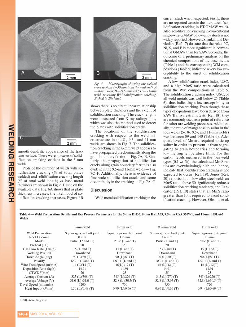
Figure 4A–C shows macrographs of thecross section (taken within 30 mm fromthe weld end) of the 8-, 9.5-, and 11-mmwelds. Weld centerline cracking is evidentin each of these welds. SEM fractography(Fig. 5A–C) confirmed that these crackdefects are solidification cracks due to the
147-sWELDING JOURNAL
WE
LD
ING
RE
SE
AR
CH
Fig. 2 — Typical macrographs of the welded cross sections (from the weld center). A — 5-mm weld; B — 8-mm weld; C — 9.5-mm weld; D — 11-mm weld,showing an increase in the weld bead depth: width ratio as thickness increases. Etched in 2% Nital.
Fig. 3 — Optical micrograph of the WM microstructure (from the weld center). A, B — 5-mm weld;C, D — 8-mm weld; E, F — 9.5 mm weld; G, H — 11 mm weld showing no significant differencesin microstructure for the four weld types. Etched in 2% Nital.
Table 2 — Nominal Chemical Composition(wt-%) of the ER70S-6 Welding Wire
C Mn Si S P
ER70S-6 0.07 1.55 0.88 0.012 0.015
Balance is Fe.
Table 3 — List of Butt Joint Welds Completed and Corresponding Weld Lengths
Weld ID Welding Wire Base Plate Weld Lengths (mm) Total Weld(no. of plates) Length (mm)
5-mm weld ER70S-6 DH36 700 (4) 2800 mm8-mm weld ER70S-6 HSLA65 700 (1), 350 (8) 3500 mm
9.5-mm weld ER70S-6 CSA 350WT 450 (4) 1800 mm11-mm weld ER70S-6 HSLA65 450 (2), 350 (1) 1250 mm
A
B
C E
D F
G
H
A B C D
Sterjovski 5-14_Layout 1 4/15/14 3:43 PM Page 147
smooth dendritic appearance of the frac-ture surface. There were no cases of solid-ification cracking evident in the 5-mmwelds.
Plots of the number of welds with so-lidification cracking (% of total plateswelded) and solidification cracking length(% of total weld length) vs. base metalthickness are shown in Fig. 6. Based on theavailable data, Fig. 6A shows that as platethickness increases, the likelihood of so-lidification cracking increases. Figure 6B
shows there is no direct linear relationshipbetween plate thickness and the extent ofsolidification cracking. The crack lengthswere measured from X-ray radiographs,which was also the method used to detectthe plates with solidification cracks.
The locations of the solidificationcracking with respect to the weld mi-crostructure in the 8-, 9.5-, and 11-mmwelds are shown in Fig. 7. The solidifica-tion cracking in the 8-mm weld appears tohave propagated predominantly along thegrain boundary ferrite — Fig. 7A, B. Sim-ilarly, the propagation of solidificationcracks along grain boundary ferrite is alsoevident in the 9.5-and 11-mm welds — Fig.7C–F. Additionally, there is evidence offine-scale solidification cracks and somediscontinuity in the cracking — Fig. 7A–C.
Discussion
Weld metal solidification cracking in the
current study was unexpected. Firstly, thereare no reported cases in the literature of so-lidification cracking in PT-GMAW welds.Also, solidification cracking in conventionalsingle-wire GMAW of low-alloy steels is notwidely reported. However, Shankar and De-vletian (Ref. 17) do state that the role of C,Ni, S, and P is more significant in conven-tional GMAW than for SAW. Secondly, theoutcome of a preliminary analysis on thechemical compositions of the base metals(Table 1) and the corresponding WM com-positions (Table 5) indicated a very low sus-ceptibility to the onset of solidificationcracking.
A low solidification crack index, USC,and a high Mn:S ratio were calculatedfrom the WM compositions in Table 5.The solidification cracking index, USC, ofall weld metals was well below 25 (Table6), thus indicating a low susceptibility tosolidification cracking. Even though thesetypes of equations have been derived fromSAW Transvarestraint tests (Ref. 18), theyare commonly used as a point of referencefor other arc welding processes. Addition-ally, the ratio of manganese to sulfur in thefour welds (5-, 8-, 9.5-, and 11-mm welds)was between 89 and 140 (Table 6). Ade-quate levels of Mn are required to tie upsulfur in order to prevent it from segre-gating to grain boundaries and forminglow melting temperature films. For thecarbon levels measured in the four weldtypes (0.1 wt-%), the calculated Mn:S ra-tios are overwhelmingly high and, hence,indicate that solidification cracking is notexpected to occur (Ref. 19). Jones (Ref.20) reports that in low-alloy steel welds anMn:S ratio above 50 significantly reducessolidification cracking tendency, and Lan-caster (Ref. 19) states that an Mn:S ratiogreater than 10 is required to avoid solid-ification cracking. However, Ohshita et al.
MAY 2014, VOL. 93148-s
WE
LD
ING
RE
SE
AR
CH
Table 4 — Weld Preparation Details and Key Process Parameters for the 5-mm DH36, 8-mm HSLA65, 9.5-mm CSA 350WT, and 11-mm HSLA65Welds
5-mm weld 8-mm weld 9.5-mm weld 11mm weld
Weld Preparation Square-groove butt joint Square-groove butt joint Square-groove butt joint Square-groove butt jointRoot Opening 0 mm 1.2 mm 1.6 mm 1.8 mm
Mode Pulse (La and To) Pulse (L and T) Pulse (L and T) Pulse (L and T)Preheat (˚C) 20 20 20 20
Gas Flow Rate (L/min) 15 (L and T) 15 (L and T) 15 (L and T) 15 (L and T)Welding Position Downhand Downhand Downhand Downhand
Torch Angle (deg) 90 (L)/80 (T) 90 (L)/80 (T) 90 (L)/80 (T) 90 (L)/80 (T)Polarity DC + (L and T) DC + (L and T) DC + (L and T) DC + (L and T)
Wire Feed Speed (m/min) 14 (L)/14 (T) 16(L) /12 (T) 16 (L)/12 (T) 16 (L)/12(T)Deposition Rate (kg/h) 14.91 14.91 14.91 14.91
CTWD C(mm) 20 25 25 25Average Current (A) 325 (L)/308 (T) 345 (L)/270 (T) 345 (L)/270 (T) 345 (L)/270 (T)Average Voltage (V) 31.0 (L) /31.0 (T) 32.8 (L)/30.5(T) 32.8 (L)/3.05 (T) 32.8 (L)/30.5 (T)
Travel Speed (mm/min) 1200 750 750 720Heat Input (kJ/mm) 0.50 (L)/0.48 (T) 0.90 (L)/0.66 (T) 0.90 (L)/0.66 (T) 0.94 (L)/0.69 (T)
ER70S-6 welding wire
Fig. 4 — Macrographs showing the weldedcross sections (~30 mm from the weld end). A— 8-mm weld; B — 9.5-mm weld; C — 11-mmweld, revealing WM solidification cracking.Etched in 2% Nital.
A B
C
Sterjovski 5-14_Layout 1 4/16/14 4:00 PM Page 148

(Ref. 11) have reported cases of solidifica-tion cracking in very low-carbon steelwelds (0.1 wt-%) using shielded metal arcwelding and GMAW.
Despite all of the above, radiographicinspection revealed solidification cracks atthe weld ends within ~30 mm from therunoff tab in many of the test plates. Thus,it can be assumed that the critical levelsfor inclusion and alloying elements lead-ing to solidification cracking are differentfor single-bead PT-GMAW than that de-termined for SAW by Transvariant or
Transvarestraint tests.These simulated solid-ification cracking testsmay be severe with re-spect to the loadingconditions the weldbead is subjected toduring solidification,but weld bead shape isnot accurately repre-sented in these typesof tests. Hoshino et al.
(Ref. 18) lend support to this view in theirassessment of the susceptibility of steelwelds to solidification cracking in narrowgroove welding, and they subsequently de-veloped an alternative solidification crack-ing test specific to their situation. It shouldbe noted that in the current work, thelength of the solidification cracks wasminor (<3% of the total welded length).Even so, crack defects will generally resultin a noncompliant weld with all the rele-vant regulatory standards in naval ship-building (Ref. 21).
The extent of solidification crackingidentified in each weld (i.e., 5-, 8-, 9.5-,and 11-mm welds) is quantified in theplots in Fig. 6. Even though these plots arebased on limited data, it is evident that asplate thickness is increased, the percent-age of plates with WM solidification crack-ing also increased (Fig. 6A), and that cracklength is less dependent on plate thickness— Fig. 6B. There is no systematic changein WM composition (Table 5) or the solid-ification cracking index (Table 6) with in-creasing plate thickness to support theincrease in the number of plates with WMsolidification cracking — Fig. 6A. Simi-larly, at the resolution of optical mi-croscopy, there is no significant differencein the WM microstructure (Fig. 3) at thedifferent plate thicknesses to offer an ex-planation for the increase in the numberof plates with solidification cracking asplate thickness is increased. Consequently,the increased cracking that is observed asplate thickness increases is mainly attrib-uted to an increase in the depth-width
149-sWELDING JOURNAL
WE
LD
ING
RE
SE
AR
CH
Table 5 — Actual Weld Metal Chemical Composition (wt-%) Using the ER70S-6 Wire
C Mn Si S P Ni Cr Mo5-mm Weld 0.10 1.16 0.44 0.013 0.016 0.02 0.04 0.01
Al B N O Cu V Nb Ti0.019 <0.0005 0.006 0.029 0.08 0.01 <0.01 0.01
8-mm Weld C Mn Si S P Ni Cr Mo0.08 1.12 0.43 0.008 0.010 0.20 0.09 0.05Al B N O Cu V Nb Ti
0.008 N/A N/A 0.034 0.21 0.008 0.013 0.005
9.5-mm Weld C Mn Si S P Ni Cr Mo0.06 1.11 0.41 0.008 0.009 0.10 0.10 0.02Al B N O Cu V Nb Ti
0.007 <0.0005 0.007 0.044 0.20 0.03 0.02 <0.01
11-mm Weld C Mn Si S P Ni Cr Mo0.07 1.22 0.42 0.010 0.010 0.02 0.03 0.02Al B N O Cu V Nb Ti
0.019 <0.0005 0.006 0.029 0.09 0.04 0.02 0.01
Balance is Fe.
Fig. 5 — Typical SEM images of the fracture surface confirming solidifica-tion cracking. A — 8-mm weld (SE); B — 9.5 mm weld (BSE); C — 11-mm weld (SE).
A
C
B
Sterjovski 5-14_Layout 1 4/15/14 3:43 PM Page 149

ratio — Fig. 2. The adverse effect of unfa-vorable weld bead geometries on the onsetof solidification cracking is well known andwidely accepted (Ref. 22). A decrease inthe width of the molten weld pool, whichcan be related to the depth:width ratio insingle-bead welds, is shown to have in-creased susceptibility in solidificationcracking (Ref. 23). Welded plates withhigher thickness are also associated withincreased restraint and increased tensileresidual stresses, both of which could alsoincrease susceptibility to solidificationcracking.
The microstructure of the weld bead inthe center of the welded plate is similar tothe microstructure at the weld end (wherethe solidification cracks are located). Thissuggests that there are no microstructuralfeatures (at the resolution of optical mi-croscopy) peculiar to the weld end re-sponsible for the onset of solidificationcracking (compare microstructures in Fig.3 to corresponding microstructures in Fig.7). Makarov et al. (Ref. 23) attribute so-lidification cracking at the weld ends tothe strain rate in the temperature range ofthe brittleness (TRB) zone, which is thegreatest at the weld ends compared withthe weld start and weld center. Makarovet al. (Ref. 23) specifically address theissue of solidification cracking at the weld
ends of 10-mm shipping steel plate. Thecracking described by them in single-sidedmulti-wire SAW is remarkably similar tothat observed in the current work with PT-GMAW and that encountered by navalshipbuilders in Australia with SAW. In aless detailed study, Hoshino et al. (Ref. 18)attribute solidification cracking in narrowgroove welds to the speed of displacementof the base metal (proportional to strainrate in the TRB).
The TRB zone is the area immediatelytrailing the fully molten weld pool, and itssize is dependent on factors such as weldprocess type, heat input, and plate thick-ness. This strain rate in the TRB zone(BTRB), which must exceed a threshold orcritical strain rate for solidification crack-ing to occur, is directly proportional to therate of transverse displacement in theplate ahead of the molten weld pool (vt),and inversely proportional to the coolingrate of the TRB zone (w0) (Equation 1).Equation 2 shows that BTRB is also pro-portional to the length of the TRB zone(lTRB) and inversely proportional to weld-ing travel speed (vw), temperature rangeof the TRB zone (TRB), and the width ofthe the molten weld pool (hp) (Ref. 23). Incontrast, Morgan-Warren and Jordan(Ref. 24) report that an increase in weldtravel speed increases the length of the
crack-susceptible zone (lTRB) but de-creases the transverse crack-promotingforces.
BTRB = vt/w0 (1)
BTRB ≈ vt × lTRB/(Vw × TRB × hp) (2)
The work of Makarov et al. (Ref. 23) isconsidered relevant to the solidificationcracking discovered in the current pro-gram, despite some of the obvious differ-ences between the two studies. Firstly, thework carried out by them was based onSAW. However, the location of the crack-ing, the role of the runoff tabs, the end-user application, and the plate thicknessjustifies drawing on this publication forreference. Secondly, the work of Makarovet al. (Ref. 23) was based on plates securedon one side, but extensive modeling workcarried out by them showed that securingplates on both sides by clamping wouldonly have a minor secondary effect on therate of transverse displacement. In thecurrent study, all plate halves wereclamped prior to welding.
There are particular characteristics ofthe single-bead PT-GMAW process thatcontribute to weld-end solidificationcracking in the welding of the naval steelsin the current work. These include 1) weldtravel speeds (shown in Table 4) above thethreshold for solidification cracking (Ref.11), 2) a long trailing weld pool comparedwith conventional single-wire GMAW thatincreases the length of the susceptible re-gion (TRB zone), 3) the ability to use asingle-bead weld, which unlike multiple-bead GMAW does not allow for the back-gouging of often problematic first (i.e.,root) runs (Ref. 11), and 4) higher deposi-tion rates (and higher arc energy heat in-puts) compared with conventionalsingle-wire GMAW resulting in a slower
MAY 2014, VOL. 93150-s
WE
LD
ING
RE
SE
AR
CH
Fig. 6 — Plot of: A — Number of welded plates with solidification cracking (%) vs. plate thickness showing that the incidences of solidification cracking increaseswith increasing plate thickness; B — solidification crack length (%) vs. plate thickness showing that the extent of cracking is not linear with plate thickness.
Table 6 — Solidification Cracking Index and Mn:S Ratio for All the Welds
Solidification Cracking Mn:S SolidificationWeld ID Index, Usc
(a) Ratio Cracking
5-mm Weld 14.1 89 No8-mm Weld 8.7 140 Yes
9.5-mm Weld 4.6 139 Yes11-mm Weld 6.5 122 Yes
(a) Usc=230C + 190S+ 75P+ 45Nb – 12.3Si – 5.4Mn–1. For butt joint welds a Usc value over 25 indicates sus-ceptibility to cracking (Ref. 19).
A B
Sterjovski 5-14_Layout 1 4/15/14 3:43 PM Page 150

cooling rate and increasing the likelihoodof solidification cracking (Ref. 23).
Solidification cracks located at the weldends and formed during the single-bead PT-GMAW of naval hull steels should be avoid-able. Makarov et al. (Ref. 23) explains thatthe runoff tab system used will influence therate of transverse displacement in the basesteels, and ultimately the likelihood of so-lidification cracking. In the current work,runoff tabs (80 × 100 mm plates) withoutgrooves and attached to the main test plateby tacking on either side of the weld prepa-ration were used. Makarov et al. (Ref. 23)reported that a 150-mm-long groove in therunoff tab for the oncoming weld to fill willsignificantly reduce the rate of transversedisplacement, and hence, reduce the likeli-hood of solidification cracking. Alterna-tively, targeted heating at the weld endsprior to welding will reduce the likelihoodof solidification cracking by seven times(Ref. 23). However, the targeted heating ap-proach is undesirable in naval shipbuildingbecause it is costly and time consuming, andif incorrectly applied could adversely impactthe integrity of the hull. A successful tech-nique currently being used in some Aus-tralian naval shipbuilding yards for thePT-GMAW of 12-mm-thick DH36 steelplate is to adopt a single-sided multiple-runweld with a temporary backing strip (Ref.6). This technique allows the manipulationof the weld process parameters to obtain adesirable weld-bead shape that is less proneto solidification cracking, and improves theimpact toughness of the WM due to thetempering effect from ensuing weld beads.However, there is an adverse impact of thistechnique on shipyard productivity com-pared with single-sided single-bead welding.
The solidification cracks found in the11-mm weld were less severe than thosefound in the other welds. Cracks in the 11-mm welds were not as long and deep com-pared with those in the 8- and 9.5-mmwelds (compare Fig. 4C with Fig. 4A, B).This was also confirmed in the radiographsof the 11-mm weld by their relatively shortlengths and lighter appearance. The smallsize of the solidification cracks in the 11-mm weld, despite it having the greatestweld bead depth-width ratio, is attributedto a significantly lower level of Ni in theWM. The 1-mm weld measured at leastfive times less Ni than 8-mm weld and tentimes less Ni than 9.5-mm weld (compareNi contents in Table 5). Nickel is reportedto increase solidification cracking ten-dency as it widens the TRB zone, increasethe solidification temperature range, in-crease the liquidus temperature, and actsin combination with sulfur to form lowmelting point nickel sulfides (Ref. 25). Infurther support on the role of Ni in weldmetal solidification cracking, Masumotoand Imai (Ref. 26) report on the segrega-tion of Ni at dendritic boundaries in steel
welds. Other elements such as Ti, Al, Cu,S, and Ca were detected by EDS in somelocations of the fracture surfaces on boththe 8- and 11-mm HSLA65 welds, but itwas not possible to establish the effect thatthey had on either the likelihood or extentof solidification cracking.
Optical microscopy, SEM, and EDSwere used to characterize the cracks lo-cated near the end of the welds, and togain insight into the potential mechanismsof crack initiation and the propagationpath. The smooth dendritic appearance ofthe fracture surfaces examined (Fig. 5A–C), confirmed that the cracks in thewelded test plates were solidificationcracks. Semiquantitative EDS analysisshowed that sulfur played an integral rolein the solidification cracking observed.Approximately twice the amount of sulfurwas detected on the fracture surface of thesolidification cracks compared with sulfurlevels distant from the cracks (also meas-ured by EDS for consistency).
Figure 7 shows optical micrographs ofWM solidification cracking and the sur-rounding microstructure in the 8-, 9.5-,and 11-mm welds. The solidificationcracks in these welds are mainly situatedalong the grain boundary ferrite — Fig. 7.The carbon levels in the 8-, 9.5-, and 11-mm welds are, respectively, 0.08, 0.05, and0.07 wt-% (Table 5). Ohshita et al. (Ref.11) report that at these very low levels ofcarbon, solidification cracking will occur
along the delta-ferrite grain boundariesduring delta-phase solidification. How-ever, this aspect has not been investigatedin the current study. Additionally, thepresence of fine/small solidification cracks(labeled in Fig. 7A and C) that appear de-tached from the main crack could be con-nected to the main crack on planes outsideof the cross section shown in these macrographs.
Conclusions
The following conclusions are drawnfrom the current work:
1) Single-bead welds produced by PT-GMAW can be susceptible to weld metal(WM) solidification cracking near theweld end (within 30 mm from the runofftab). Characteristic features of the single-bead PT-GMAW process that contributeto this type of cracking include high weldtravel speeds, a long trailing weld pool,high deposition rates, and slow coolingrates compared with welding proceduresthat would be used for conventional sin-gle-wire GMAW.
2) The incidence of WM solidificationcracking was found to increase with in-creasing plate thickness. This was attrib-uted to an increase in the weld beaddepth:width ratio and joint restraint withincreasing plate thickness, and critical lev-els of impurity and alloying elements inthe weld metal.
151-sWELDING JOURNAL
WE
LD
ING
RE
SE
AR
CH
Fig. 7 — Optical micrographs showing the WM solidification crack and surrounding microstructure. A, B —8-mm weld; C — 9.5-mm weld; D, E, F — 1-mm weld. Etched in 2% Nital.
A B C
D E F
Sterjovski 5-14_Layout 1 4/15/14 3:43 PM Page 151

MAY 2014, VOL. 93152-s
WE
LD
ING
RE
SE
AR
CH
3) The sizes of solidification cracks inthe 11-mm weld were smaller than thecracks in the 8- and 9.5-mm welds. Weldmetal with significantly less Ni was attrib-uted to limiting the size of the solidifica-tion cracks.
4) The levels of impurity elements (Sand P) measured in the weld metal weresignificantly lower than that reported toincrease the risk of solidification crackingin solidification cracking in submerged arcwelds. Similarly, the Mn:S ratios calcu-lated for each of the weld metals were sub-stantially greater than that reported toincrease the risk of solidification crackingin the literature that was reviewed.
Acknowledgments
The authors would like to acknowledgethe Defence Materials Technology Centre(DMTC) for its ongoing support. We wouldalso like to thank Dr. Len Davidson, Dr.Stan Lynch, and Dr. Stuart Cannon fromDSTO for their support of this work and re-view of this paper. The authors would alsolike to acknowledge the support of Dr. Al-lison Nolting, Cameron Munro, andAlexandra McLeod from DRDC Atlantic,Johnnie DeLoach from NSWC–CarderockDivision, and Prof. John Norrish from Uni-versity of Wollongong. We also gratefullyacknowledge the efforts of Paul Calleja,Joseph Dominguez, and Frank Griffo fromDSTO for their assistance with welding,welding preparation, postweld sectioning,and SEM EDS analysis.
References
1. Yudobidroto, B. Y. B., Hermans, M. J.M., and Richardson, I. M. 2006. The influence
of pulse synchronisation on the process stabilityduring tandem wire arc welding. IIW Doc. No.XII-1910-06, International Institute of Welding.
2. Sterjovski, Z., Donato, J., and Li, H. 2011.The effect of travel speed and CTWD on thebead profile and microstructure of tandemGMA steel welds. Australasian Welding Journal,1st Quarter, pp 40–46.
3. Sterjovski, Z., Donato, J., Munro, C.,Lane, N., Luzin, V., and Larkin, N. 2011, Anevaluation of pulsed tandem GMAW ofHSLA65 steel for naval shipbuilding. 6th AsianPacific IIW International Congress and 56thWTIA Annual Conference, Cairns, Australia.
4. Sampath, K. 2006. An understanding ofHSLA-65 plate steels. Journal of Materials En-gineering and Performance 15(1): 32–40.
5. Barsoum, R. G. S. 2005. United StatesPatent – Hybrid Ship hull, US 6941888B2.
6. Lang, D. 2012. Weld Procedure Qualifi-cation PQR-7139-Tandem GMAW, single-sidewelded single vee butt weld-12 mm ASTMA322 DH36. Forgacs Engineering Pty Ltd.
7. Sterjovski, Z., Donato, J., Munro, C.,Lane, N., Luzin, V., and Larkin, N. 2011. Ap-plication of pulsed tandem gas metal arc weld-ing for fabrication of high strength steel panelsin naval surface vessels. Australasian WeldingJournal 4: 37–48.
8. Larkin, N., Pan, Z., van Duin, S., Lane,N., and Li, H. 2010. Feasibility testing of T-GMAW for low distortion butt welds. DMTCReport.
9. Sutton, B. J. 2013. Solidification behaviorand hot cracking of high manganese steel weldmetals. Thesis, The Ohio State University.
10. Kannengiesser, T., Rethmeier, M.,Portella, P. D., Ewert, U., and Redmer, B. 2011.Assessment of hot cracking behaviour in welds.Int. J. Mat. Res. 102(8): 1001.
11. Ohshita, S. Yurioka, N., Mori, N., andKimura, T. 1983. Prevention of solidificationcracking in very low carbon steel welds. WeldingJournal 62(5): 129-s to 136-s.
12. Machado, I. G. 1984. Weldability aspectsof high yield strength Q and T steels. PhD the-sis, Cranfield Institute of Technology.
13. ASTM International. 2008. A131M-08.
14. Canadian Standards Association. 2004.G40.20, General Requirements for Rolled orWelded Structural Quality Steels, Mississauga ,Ontario, 2004.
15. ASTM International. 2006.A945/A945M-06.
16. Standards Australia. 2006. AS2177-2006.17. Shankar, V., and Devletian, J. H. 2005.
Solidification cracking in low alloy steel welds.Science and Technology of Welding and Joining10(2): 236.
18. Hoshino, K., Yamashita, R., Shinoda, T.,and Ono, H. 1988. Solidification cracking innarrow gap welded joints. Proc. 7th InternationalConference on Offshore Mechanics and ArcticEngineering, Houston, Tex. 7(12): 45.
19. Lancaster, J. F. 1999. Metallurgy of Weld-ing, 6th Ed., Abington Publishing, Cambridge,England.
20. Jones, P. W. 1959. An investigation of hotcracking in low-alloy steel welds. British Weld-ing Journal 6(6): 282–290.
21. McLeod, A., and Bayley, C. 2012. Mi-crostructural investigation of PT-GMAW weldingdefects. Letter Report, DRDCAtlantic/DLP/3771-7-2.1203776, DRDC Atlantic.
22. Messler, R. W. Jr. 2004. Principles ofWelding Processes, Physics, Chemistry and Met-allurgy. Wyley-VCH, Weinhein.
23. Makarov, E., Herold, H., Schhtraiten-berg, M., and Pshennikov, A. 2000. Preventinghot cracking in end sections of long welds inone-sided, multi-arc, submerged-arc welding.Welding International 14(4): 305–309.
24. Morgan-Warren, E. J., and Jordan, M. F.1976. Effect of travel speed on solidificationcracking in autogenous tungsten inert gas arcwelding of low-alloy steel sheet. Metals Tech-nology 1: 29–39.
25. Matsuda, F., and Savage, W. F. 1969. Ef-fect of individual alloying element on hot-crack-ing of two low alloy steels. Technical Report,Osaka University, 19(867/907), 467–491.
26. Masumoto, I., and Imai, K. 1970. A met-allurgical aspect of hot cracking and toughnessof weld metal. Trans. Jap. Weld Res, Inst. 1(1):104–111.
Authors: Submit Research Papers Online
Peer review of research papers is now managed through an online system using Editorial Man-ager software. Papers can be submitted into the system directly from the Welding Journal page on theAWS website (www.aws.org) by clicking on “submit papers.” You can also access the new site di-rectly at www.editorialmanager.com/wj/. Follow the instructions to register or log in. This online sys-tem streamlines the review process, and makes it easier to submit papers and track their progress.By publishing in the Welding Journal, more than 69,000 members will receive the results of yourresearch.
Additionally, your full paper is posted on the American Welding Society Web site for FREE ac-cess around the globe. There are no page charges, and articles are published in full color. By far, themost people, at the least cost, will recognize your research when you publish in the world-respectedWelding Journal.
Sterjovski 5-14_Layout 1 4/17/14 7:58 AM Page 152