Supplement to AS 1742.14:2014 Manual of uniform traffic ...
20
vicroads.vic.gov.au Supplement to AS 1742.14:2014 Manual of uniform traffic control devices Part 14: Traffic Signals OCTOBER 2015
Transcript of Supplement to AS 1742.14:2014 Manual of uniform traffic ...

VicRoads Supplement to AS 2890.1: 2004 – Edition 1 1 October 2015
vicroads.vic.gov.au
Supplement to AS 1742.14:2014 Manual of uniform traffic control devices Part 14: Traffic Signals
OCTOBER 2015

VicRoads Supplement to AS 1742.14:2014 – Edition 1 2 October 2015
Table of Contents
1. Introduction ............................................................................................................... 3
1.1 General .............................................................................................................. 3
1.2 How to Use this Supplement .............................................................................. 3
2. List of Differences ..................................................................................................... 4
3. Details of Changes .................................................................................................... 5
Clause 2.3.2 – Flashing yellow arrow .......................................................................... 5
Clause 2.4 (d) – Pedestrian countdown timer .............................................................. 5
Clause 4.1.4 – Overhead Signal Faces ....................................................................... 5 Mast arms ...............................................................................................................................5
Size of mast arms ...................................................................................................................5
Mini mast arm (1.4 m outreach) .............................................................................................6
Clause 4.2.1 – General ............................................................................................... 8
Clause 5.6 – Pedestrian Push Buttons ........................................................................ 9 Pedestrian push button detectors...........................................................................................9
Audio-tactile pedestrian push button ................................................................................... 10
Clause 6.1 – SIGNS .................................................................................................. 10 U TURN MUST GIVE WAY ................................................................................................. 10
Every second cycle sign ...................................................................................................... 10
Reversible Lanes ................................................................................................................. 11
Clause 6.1.2 – Application ........................................................................................ 11
Clause 6.1.2 (c) – U-turn permitted (R2-15) .............................................................. 12
Clause 6.1.2 (d) – Hook Turn Only (R2-21) ............................................................... 12
Clause 6.1.2 (e) – Pedestrian may cross diagonally (scramble crossing) (R3-5) ....... 12
Clause 6.2.1 – Stop Lines ......................................................................................... 14
Clause 6.2.2 – Pedestrian Crosswalks ...................................................................... 14 Diagonal Pedestrian Crossing ............................................................................................. 15
Clause 6.2.3 – Intersection Arrows............................................................................ 15
Clause 6.2.4 – Turn Lines ......................................................................................... 15
Clause 7.1 – Signals for Emergency Service Facilities .............................................. 18
Clause 7.2.2 – Design and Operation ....................................................................... 18
Clause 7.2.3 – Location and installation .................................................................... 19
Clause 7.5 – LEFT TURN ON RED AFTER STOPPING ........................................... 19
Document Information ............................................................................................................ 20

VicRoads Supplement to AS 1742.14:2014 – Edition 1 October 2015
3
1. Introduction 1.1 General All road agencies across Australia are working towards greater consistency between States/Territories in how road networks are managed. In order to achieve this, the Austroads Guide to Traffic Management and Australian Standards relating to traffic management have been adopted to assist in providing that level of consistency and harmonisation across all jurisdictions. This agreement means that these Austroads Guides and the Australian Standards are the primary technical references.
Australian Standards AS 1742.14:2014 - Manual of uniform traffic control devices – Part 14: Traffic Signals is a nationally agreed standards document outlining the use of traffic control devices on the road network and has been adopted by all jurisdictions, including VicRoads.
All jurisdictions will be developing their own supplement to clearly identify where its practices currently differ and to provide additional guidance to that contained within AS 1742.14:2014. This document is the VicRoads supplement and shall be read in conjunction with AS 1742.14:2014.
1.2 How to Use this Supplement There are two key parts to this document:
Classification of Supplement Information: this table classifies supplement information as a Departure, Additional Information or both. This information assists with identifying its hierarchy in relation to the Australian Standard.
• Details of Supplement Information: this section provides the details of the supplement information.
takes precedence
in conjunction
Departures: where VicRoads practices differ from the guidance in the Australian Standard. Where this occurs, these differences or ‘Departures’ will be highlighted in a box. The information inside the box over the Australian Standard clause. The Australian Standard clause is not applicable in these instances.
Additional Information: all information not identified as a departure provides further guidance to the Australian Standard and is read and applied with the Australian Standard clause.
Where a clause does not appear in the body of this supplement, the Australian Standard requirements are followed.

VicRoads Supplement to AS 1742.14:2014 – Edition 1 October 2015
4
2. List of Differences The classification of each clause as a Departure, Additional Information or both is shown in the table below.
Clause Classification
2.3.2 Additional Information
2.4 (d) Additional Information
4.1.4 Additional Information
4.2.1 Additional Information
5.6 Additional Information
6.1 Additional Information
6.1.2 Additional Information
6.1.2 (c) Additional Information
6.1.2 (d) Additional Information
6.1.2 (e) Additional Information
6.2.1 Additional Information
6.2.2 Additional Information
6.2.3 Additional Information
6.2.4 Additional Information
7.1 Departure / Additional Information
7.2.2 Additional Information
7.2.3 Additional Information
7.5 Departure
Australian Standard requirements are followed for clauses not shown in this table.

VicRoads Supplement to AS 1742.14:2014 – Edition 1 October 2015
5
3. Details of Changes Clause 2.3.2 – Flashing yellow arrow The use of the flashing yellow arrow, as described in Clause 2.3.2 of AS 1742.14:2014, has not been used in Victoria. The use of the flashing GIVE WAY TO PEDESTRIAN sign, which is located adjacent to the traffic signal lantern, is considered to be sufficient in warning drivers of the presence of pedestrians during a green pedestrian phase.
Should a flashing yellow arrow be proposed for use in Victoria, it should not be installed at an isolated intersection, as it may cause driver confusion. Instead, multiple sites within a locality should be considered, with an appropriate community awareness strategy to clarify driver obligations.
Clause 2.4 (d) – Pedestrian countdown timer The use of a yellow countdown timer display to replace the flashing red pedestrian symbol shall only be considered for use in:
• a Pedestrian Priority Area under the SmartRoads Road Use Hierarchy • an area of significant pedestrian activity, at locations in regional Victoria where the Road Use Hierarchy
is yet to have been developed.
Use of a yellow countdown timer display outside the above areas requires approval from the Director – Network Policy and Standards.
Clause 4.1.4 – Overhead Signal Faces Mast arms
Mast arms (MA) have been designed to fulfil two objectives:
• To support a lantern over or to the side of an obstruction, which is inhibiting the visibility of the primary lantern.
• To reduce the offset of the primary lantern from the driver’s line of sight (desirable maximum offset 7.5 m).
Mast arms should only be installed at intersection signals if:
• There are more than three approach lanes at the stop line and there is no approach side median suitable for a pole with a dual-primary signal face.
• Visibility of pole-mounted signal faces is impeded.
Size of mast arms
Mast arms are available with four outreach lengths. These are shown in Table 1.
• Mini mast arms: o 1.4 m
• Standard mast arms: o 2.5 m o 3.7 m o 5.5 m
The lantern on the outreach of a mast arm is over the road pavement and must be at a sufficient height so that vehicles do not collide with it. Therefore the mast has been designed to provide a 5.5 m clearance from the road pavement.
Due to the need to provide electrical clearance between mast arm and overhead electricity cable (see Figure 1), mast arms should normally be installed in the median strip on a divided road. This location also ensures that:
• The overhead lantern is nearest to fastest moving vehicles. • If an indented right turn lane exists, there is a lantern clearly visible above the through lane.

VicRoads Supplement to AS 1742.14:2014 – Edition 1 October 2015
6
Figure 1: Signal Hardware Clearance Required Under Electricity and Tram Operator Lines
Mini mast arm (1.4 m outreach)
VicRoads ITS Standard Drawing TC 1103 shows the mini mast arm to be of one size only - one which provides a 5.5 m road clearance to the 1.4 m outreach. At this height, it cannot be used under 240 V power lines, which are generally hung 7.0 m above ground level, as the ESA clearance would be violated. Clearance to power lines for all hardware is shown in Figure 1.
However, the mini mast arm can have its height reduced by 400 mm where it is to be installed under 240 V power lines. Clearance of 4.9 m for all non over dimensional vehicles will still be maintained.
Therefore, where necessary, design plans may specify the mini mast arm as 4.9 m x 1.4 m MA, although 5.5 m x 1.4 m MA should be specified whenever possible.
Table 1: Pole and mast arm specifications including vertical clearance and outreach requirements
Vertical Clearance m
Outreach m
Pole Height m
Joint Use Pole (JUP) - - 8.5, 11, 13.5
Mini Mast Arm (Mini MA) 4.9 to 5.5 1.4 -
Mast Arm (MA) 5.5 2.5, 3.7, 5.5 -
Joint Use Mast Arm (JUMA) 5.5 2.5, 3.7, 5.5 8.5, 11, 13.5
Note: Mounting height of a street lighting lantern is 1.5 m above pole height.

VicRoads Supplement to AS 1742.14:2014 – Edition 1 October 2015
7
The various pedestal types used by VicRoads are shown in Figure 2.
Figure 2: Various pedestal types and signal components

VicRoads Supplement to AS 1742.14:2014 – Edition 1 October 2015
8
Clause 4.2.1 – General Additional guidance on the placement of signal faces at intersections is shown below.
Figure 3: Location of signal displays, undivided roads

VicRoads Supplement to AS 1742.14:2014 – Edition 1 October 2015
9
Figure 4: Location of signal displays, divided roads
Clause 5.6 – Pedestrian Push Buttons Pedestrian push button detectors
Pedestrian push button detectors are shown on the same pedestals as the pedestrian lanterns at each end of the crosswalk. If the crosswalk passes over a median greater than 1.5 m, then a pedestrian detector is provided. If in some instances, it is necessary to locate the pedestrian detector away from the primary or secondary pedestals, then a type 3 pedestal (a 1 m high pedestal) is used. The most frequent use of a type 3 pedestal is on safety zones.
Generally, audio-tactile detectors (audible signals) should be specified for all new signal installations. Detectors with constant and variable sound output are available. Variable detectors adjust output according to ambient noise levels and should be used adjacent to residential properties.
There is an increasing practice of turning the audible signals off at night where residential properties are close to the pedestrian crossing and the audible signal causes disturbance. Consultation with any local associations for the vision impaired should be considered. The signal controller will need to be reprogrammed for the new operating times.

VicRoads Supplement to AS 1742.14:2014 – Edition 1 October 2015
10
A note needs to be added to the traffic signal layout plan if audible signals are to be installed.
Audio-tactile pedestrian push button
The audio-tactile pedestrian push button provides audible and tactile features to assist the hearing and vision impaired. The device indicates when the pedestrian phase is operating and when pedestrians should not cross. The push button assembly also has a raised arrow above the push button that provides directional orientation relating to the direction of the crosswalk.
The pedestal and pedestrian push button shall be positioned within the zone of common reach for people either standing or in a standard wheelchair. This distance is within an offset range of 300 mm to 400mm of the adjacent pathway.
The push button is installed at a height of 1 m from the ground. The push button assembly should be placed on the front of the pole with the face perpendicular to the crossing, and with the arrow pointing upwards.
However, the assembly may be placed on the side of the pole with the arrow horizontal where:
• the pole is in a median and a double-ended arrow is used • placement on the front of the pole could cause ambiguity or confusion.
Where an existing signal pedestal is remote from the crosswalk, consideration may need to be given to the installation of a Type 3 pedestal (1 m high) in the preferred location.
Clause 6.1 – SIGNS U TURN MUST GIVE WAY
Under rule 38 of the Road Safety Road Rules 2009, drivers performing a U-turn at an intersection must give way to all other turning vehicles. The sign reinforces this rule.
Sign R2-V115 U TURN MUST GIVE WAY should not be used at intersections simply to support the road rule.
The sign is used at signalised intersections that have a green right turn arrow on the major road operating concurrently with a green left turn arrow on the side road. Under these circumstances, both drivers have a green light, which may lead a vehicle performing a U-turn into a conflict with a vehicle concurrently undertaking a left turn.
The sign is placed on the signal pedestal or a short distance in front of it facing a driver performing a U-turn movement on the major road, thus alerting the driver to a potential conflict.
R2-V115
Every second cycle sign
Capacity constraints on the road network have resulted in the need to assess which vehicle movement can be delayed or queued in order to meet the demands of the critical vehicle movements and intersection capacity. In some situations where the volume of a right turn movement is minor, it may be considered suitable to operate the minor right turn in every second traffic signal cycle (or every third cycle, etc.). A description and the warrants for operating a fully controlled right turn every second cycle is discussed in Section 7.3.3 of the VicRoads Supplement to Austroads Guide to Traffic Management Part 9 (2014).

VicRoads Supplement to AS 1742.14:2014 – Edition 1 October 2015
11
At intersections where this method of control is implemented, sign G9-V200-1 with the message ‘RIGHT TURN MAY OPERATE EVERY 2ND CYCLE’ may be installed on the signal pedestal or a short distance in front, facing drivers in the affected right turn lane.
At intersections with Red Light Cameras, a supplementary plate shall be installed, which also identifies the days and time periods of operation (refer to AS 1742.2 Clause 2.8.10 (a)).
G9-V200-1
Reversible Lanes
Signs similar to R2-V120 are used to provide advance warning to motorists of the conditions that prevail on roads where a reversible lane is used to improve road capacity.
The times displayed on signs at both ends of the reversible lane must differ to take into account the clearance time required to safely change the direction of flow.
The signs must be placed at intervals not exceeding 500 m and in a conspicuous location, not only for traffic using the road that has reversible flow, but also for traffic entering from significant side roads.
The sign is also used with the word AHEAD to advise motorists in advance that reversible flow applies.
Variable message signs may also be used to inform drivers of important changes to lane operation as indicated by overhead lane signals.
Prior to the installation of this form of lane control, the Director – Network Policy and Standards should be consulted regarding the signs and line marking arrangement proposed.
R2-V120
Clause 6.1.2 – Application Traffic control devices as referred to in the Road Safety (Traffic Management) Regulations 2009 (including signs listed in this Clause), when erected or displayed at or near a traffic control signal are Major Traffic Control Devices and are generally not delegated to local councils (refer to Traffic Engineering Manual Volume 3 Part 2.1).
At a left turn slip-lane which requires entering traffic to give way to the intersecting traffic stream, a GIVE WAY sign shall be provided (refer to AS 1742.2:2009 Clause 2.5.5 for further details).

VicRoads Supplement to AS 1742.14:2014 – Edition 1 October 2015
12
Clause 6.1.2 (c) – U-turn permitted (R2-15) This sign is not required at signalised intersections in Victoria as U-turns are generally allowed as per the Road Safety Road Rules 2009.
Clause 6.1.2 (d) – Hook Turn Only (R2-21) Right turn from the left (hook turn) signs are used extensively in the Melbourne Central Activities District, on streets where trams operate, to assist the movement of traffic and provide for safe right turns.
Where traffic flow is heavy, road widths are restricted and right turn phases are not practical, provision is made in the intersection layout to allow right turn vehicles to store on the left of the intersection clear of the through traffic lanes, allowing better traffic movement through the intersection. Its purpose is also to maintain a clear passage for trams.
In city areas with high pedestrian volumes, conventional right turn operation may lead to the situation where both traffic lanes are held up, blocked respectively by a right turn vehicle in the right lane and a left turn vehicle in the kerb lane waiting for pedestrians to clear the pedestrian cross-walk. It may only need one turning vehicle in each lane to hold up all the through vehicles.
Hook turns can be used on one road and conventional right turns on the other road but hook turns and conventional turns should not be used together on the same road at an intersection.
Hook turns are safer for pedestrians, as the right turning traffic can only move off in the next part of the traffic signal cycle in conjunction with the adjacent (or side road) traffic, rather than turning through pedestrians on the pedestrian crossing.
Right turn from left signs are restricted to signalised intersections.
The sign shall be installed within the intersection and mounted overhead. The sign shall operate at all times (i.e. no time of operation supplementary sign is permitted).
In addition to the above, an advance version of R2-21 sign shall be installed prior to the intersection either overhead or side mounted on the right side where a median or tram safety zone exists. The word ‘ONLY’ on the bottom of this sign shall be replaced by the word ‘AHEAD’.
The right turn from left sign is a Major Traffic Control Device and is not delegated to local councils (refer to Traffic Engineering Manual Volume 3 Part 2.1).
The road rules for a right turn from left sign is given in rules 34, 35 and 36 of the Road Safety Road Rules 2009.
Clause 6.1.2 (e) – Pedestrian may cross diagonally (scramble crossing) (R3-5) Diagonal pedestrian crossings may be provided in central business districts where there are high pedestrian volumes, which affect the capacity of the intersection due to geometric restraints.
This facility is only installed when it would lead to a more efficient signal phasing operation. Vehicular traffic is required to stop on all approaches to the intersection and pedestrians are permitted to cross the intersection diagonally.
The Manager – Network Standards shall be consulted when installation of this facility is contemplated. See Figure 5 for a typical diagonal pedestrian crossing arrangement.

VicRoads Supplement to AS 1742.14:2014 – Edition 1 October 2015
13
Figure 5: Typical diagonal pedestrian crossing arrangement
Notes to Figure 5:
1. Additional pedestrian lanterns facing diagonally across the intersection are required.
2. Pedestrian May Cross Diagonally sign (R3-5) may be installed on all legs of intersection to supplement signal lantern and linemarking arrangements

VicRoads Supplement to AS 1742.14:2014 – Edition 1 October 2015
14
Clause 6.2.1 – Stop Lines The width of all stop lines at signalised intersections shall be 600 mm in Victoria. This line thickness provides enhanced conspicuity in adverse viewing conditions (e.g. wet weather) and distinguishes this stop line from other stop lines at non-signalised intersections.
Clause 6.2.2 – Pedestrian Crosswalks Pedestrian crosswalk lines in Victoria now use the broken line pattern as described in AS 1742.14:2014 Clause 6.2.2. The following strategy has been adopted to transition to the broken line standard. Where an existing intersection / crossing is being resurfaced, which contains crosswalk lines of the previous continuous line pattern, the guidance below shall be followed:
• If the works involve the removal of the entire crosswalk line, then a crosswalk line in the new broken pattern shall be installed.
• If only a portion of the crosswalk line is removed (e.g. only one of the two lines), then a crosswalk line using the previous continuous line pattern should be installed to match the rest of the existing line.
Pedestrian cross walk lines are located to:
• minimise the pedestrian crossing distances • be as near as possible to pedestrian desire lines
Pedestrian cross walk lines should be as near as possible to the corner to:
• ensure maximum visibility of pedestrians by turning motorists • to minimise the distance from the stop line to the point where left turns conflict with the parallel
pedestrian movement so that the speed of left turning vehicles at the conflict point is minimised • minimise the distance from the stop line to the cross walk on the far side of the intersection so that the
time for through vehicles to clear the intersection is minimised.
The relationship between the stop and pedestrian cross walk lines is shown in Figure 6.
Figure 6: Typical pedestal and linemarking arrangement
Pedestrian crosswalk lines are only used at:
• signalised crossings • unsignalised school or children's crossings.
They are not used at unsignalised crossings such as at unsignalised left turn slip lanes, or pedestrian refuges to define pedestrian walking paths.
At intersections, the line nearer the intersection should be a minimum of 1.2 m clear of the edge of the cross traffic lane.

VicRoads Supplement to AS 1742.14:2014 – Edition 1 October 2015
15
Diagonal Pedestrian Crossing
Refer to Clause 6.1.2 (e) of this Supplement for details on diagonal pedestrian crossing linemarking.
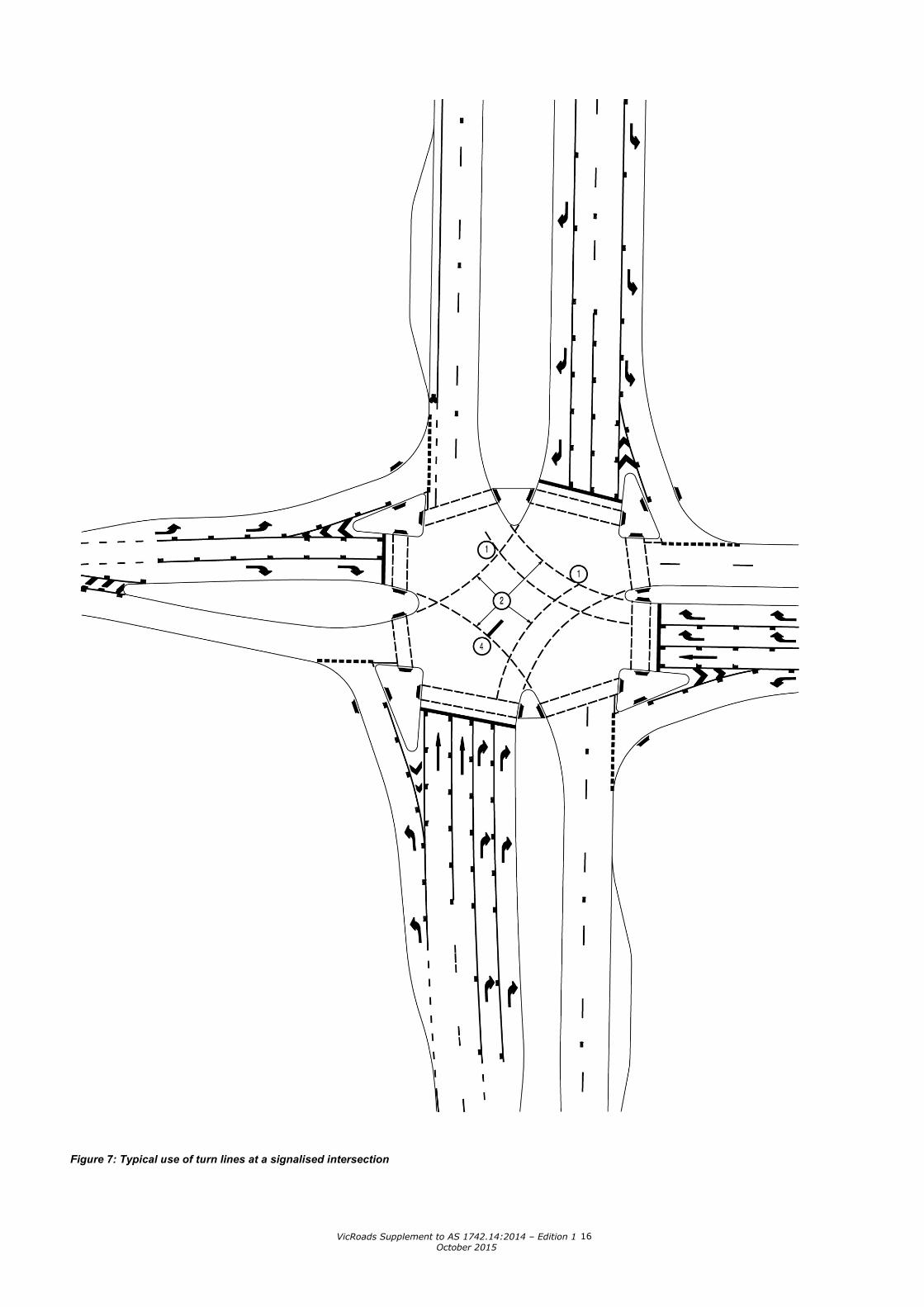
Clause 6.2.3 – Intersection Arrows Figure 7 and Figure 8 provide additional information regarding the placement of intersection arrows at typical signalised intersections.
Clause 6.2.4 – Turn Lines Turn lines in Victoria now use the broken line pattern as described in AS 1742.14:2014 Clause 6.2.4. The following transition strategy has been adopted to transition to the broken line standard. Where an existing intersection is being resurfaced which contains turn lines of the previous continuous line pattern, the guidance below shall be followed:
• If the works involve the removal of the entire turn line, then a turn line in the new broken pattern shall be installed.
• If only a portion of the turn line is removed (e.g. only half of the line), then a turn line using the previous continuous line pattern shall be installed to match the rest of the existing line.
Turn lines are normally required when one or more of the following conditions apply:
• Undivided approaches on opposite sides of an intersection have separation lines offset by more than 3 m.
• The intersection is on a summit vertical curve such that right turning drivers could be unsure of their direction of travel.
• One or more of the approaches is sharply angled. • The divided road carriageway width on two or more approaches exceeds 10.5 m. • The right turn movement is from two or three lanes turning in the same direction. • Other features make the turning path difficult to follow.
At cross intersections, clearance to meet the swept path requirements shall be provided for opposing right turn vehicles.
When a driver of a right turning vehicle filtering through an intersection has difficulty in determining where to stop, which may be due to the curvature of the road and/or vehicles making a right turn from the opposite direction, a 300 mm wide hold line may be marked to indicate where to wait prior to completing their turn, see note 4 of Figure 7.
An example of the use of turn lines is shown in Figure 7 and Figure 8.
VicRoads Supplement to AS 1742.14:2014 – Edition 1 October 2015
16
Figure 7: Typical use of turn lines at a signalised intersection

VicRoads Supplement to AS 1742.14:2014 – Edition 1 October 2015
17
Figure 8: Special use of turning lines at the intersection of major arterial roads
VicRoads Supplement to AS 1742.14:2014 – Edition 1 October 2015
18
Notes to Figure 7 and Figure 8:
1. The second turn line is normally terminated at the prolongation of the opposing through lane. However, it may be extended across the opposing through lanes at large and/or complex intersections where this is necessary for guidance.
2. Adequate separation of turn lines should be provided to meet the swept path requirements of opposing right turning vehicles, turning concurrently. In special cases where split right turn phases are used, a lesser width may be used as shown in Figure 8.
3. Broken turning line guides left turn traffic into the appropriate lanes; turning line continues to meet lane line.
4. A 300 mm wide hold line may be installed to indicate the location where turning traffic may stop when filtering, so as not to conflict with the opposing through movement.
Clause 7.1 – Signals for Emergency Service Facilities DEPARTURE
VicRoads does not use the flashing red signals (double flashing red lights) at new sites, as there is a risk that drivers may not be familiar with this signal operation and may not stop when the signals are operating.
Three-aspect signal faces should be used instead of two-aspect signal faces in most situations. The sudden activation of the two-aspect signals, where previously no signal was displayed, could possibly cause confusion, especially for drivers not familiar with the site.
For additional information regarding the operation of signals at emergency service facilities, refer to Clause 8.5.3 of the Supplement to Austroads Guide to Traffic Management Part 10 (2009).
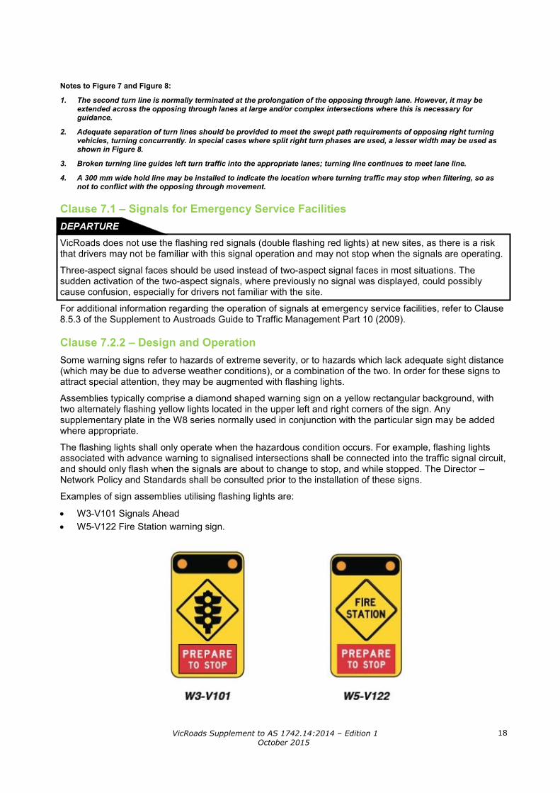
Clause 7.2.2 – Design and Operation Some warning signs refer to hazards of extreme severity, or to hazards which lack adequate sight distance (which may be due to adverse weather conditions), or a combination of the two. In order for these signs to attract special attention, they may be augmented with flashing lights.
Assemblies typically comprise a diamond shaped warning sign on a yellow rectangular background, with two alternately flashing yellow lights located in the upper left and right corners of the sign. Any supplementary plate in the W8 series normally used in conjunction with the particular sign may be added where appropriate.
The flashing lights shall only operate when the hazardous condition occurs. For example, flashing lights associated with advance warning to signalised intersections shall be connected into the traffic signal circuit, and should only flash when the signals are about to change to stop, and while stopped. The Director – Network Policy and Standards shall be consulted prior to the installation of these signs.
Examples of sign assemblies utilising flashing lights are:
• W3-V101 Signals Ahead • W5-V122 Fire Station warning sign.
VicRoads Supplement to AS 1742.14:2014 – Edition 1 October 2015
19
Clause 7.2.3 – Location and installation Where active advance warning signals are being provided for traffic signals installed in isolated rural locations, or in other situations where traffic signals may not be expected, the advance warning signals should be positioned at the Stopping Sight Distance away from the stop line. Refer to Section 5.3 of the Austroads Guide to Road Design, Part 3 for further information on Stopping Sight Distances.
Clause 7.5 – LEFT TURN ON RED AFTER STOPPING DEPARTURE
Left turn on red (LTOR) is not used in Victoria. This is due to safety concerns about the conflict between left turning vehicles and pedestrians crossing the approach that the vehicle is turning from. Although the guidelines for use of LTOR minimise the chances of such conflicts by only allowing LTOR where there are few pedestrians and simple geometry, these conflicts can occur nevertheless. In New South Wales, some of the LTOR signs are being removed where there have been crashes, near-crashes or perceptions of safety concerns. The approach in Victoria has always been to place a higher value on safety. Hence, VicRoads’ policy is to not allow such operation.

VicRoads Supplement to AS 1742.14:2014 – Edition 1 October 2015
20
Document Information
Title: VicRoads Supplement to AS 1742.14:2014 – Edition 1
Department: Network Standards
Directorate: Policy and Programs
Approved by: Manager – Network Standards
Date of Approval: October 2015
Amendment Record
Edition / Revision Pages(s) Issue Date Amendment Description
AS 1742.14:2014 – Edition 1
All October 2015 First Edition –
Previous versions of this document are available on request by contacting the VicRoads – Network Standards team.
For enquiries regarding this supplement, please contact the VicRoads – Network Standards team via [email protected] or 9854 2417.