![Global Subsonic and Subsonic-Sonic Flows through Infinitely … · 2018. 11. 1. · arXiv:0907.3274v1 [math.AP] 19 Jul 2009 Global Subsonic and Subsonic-Sonic Flows through Infinitely](https://static.fdocuments.us/doc/165x107/60cc91b2435c55467c1b4ed5/global-subsonic-and-subsonic-sonic-flows-through-ininitely-2018-11-1-arxiv09073274v1.jpg)
SUPIN: A Computational Tool for Supersonic Inlet … · formed a starting point for many of the...
16
American Institute of Aeronautics and Astronautics 1 SUPIN: A Computational Tool for Supersonic Inlet Design John W. Slater * NASA John H. Glenn Research Center, Cleveland, Ohio 44135 A computational tool named SUPIN is being developed to design and analyze the aerodynamic performance of supersonic inlets. The inlet types available include the axisymmetric pitot, three-dimensional pitot, axisymmetric outward-turning, two- dimensional single-duct, two-dimensional bifurcated-duct, and streamline-traced inlets. The aerodynamic performance is characterized by the flow rates, total pressure recovery, and drag. The inlet flowfield is divided into parts to provide a framework for the geometry and aerodynamic modeling. Each part of the inlet is defined in terms of geometric factors. The low-fidelity aerodynamic analysis and design methods are based on analytic, empirical, and numerical methods which provide for quick design and analysis. SUPIN provides inlet geometry in the form of coordinates, surface angles, and cross-sectional areas. SUPIN can generate inlet surface grids and three-dimensional, structured volume grids for use with higher-fidelity computational fluid dynamics (CFD) analysis. Capabilities highlighted in this paper include the design and analysis of streamline-traced external-compression inlets, modeling of porous bleed, and the design and analysis of mixed-compression inlets. CFD analyses are used to verify the SUPIN results. I. Introduction ver the past 70 years, various computational methods have been applied for the design of supersonic inlets. Analytic methods for shock waves and compressible flow, such as those documented in the NACA Report 1135 formed a starting point for many of the methods. 1 Empirical methods derived from wind-tunnel studies provided information on such flow properties as shock stand-off distances and total pressure loss through subsonic ducts. 2,3 The books by Seddon and Goldsmith, Mahoney, and Anderson provide basic and applied methods for inlet design and analysis. 4,5,6,7 Such methods were coded into computational tools such as the US Air Force Level II Installation Code, the US Navy NIDA Code, and the NASA Inlet Performance Analysis Code (IPAC). 8,9,10 The InletMOC and LercInlet codes incorporated the method of characteristics for planar compressible flow for the analysis and design of external and internal supersonic diffusers. 11,12 The LAPIN code solved the unsteady, quasi-one-dimensional Euler equations to analyze steady and unsteady flow within mixed-compression inlets. 13 The methods of computational fluid dynamics (CFD) have been applied to solve the unsteady, three-dimensional, viscous flow through supersonic inlets. 14,15 The increased fidelity and flow field detail possible with CFD methods requires greater complexity and time for the analysis. The present work has the objective of retaining the capability of the various past tools while updating and documenting the coding and methods. The objective is to develop a computational tool to provide a capability to design and analyze traditional inlet types, such as the axisymmetric and two-dimensional inlets, as well as, develop a tool to design and analyze newer inlet concepts, such as the streamline-traced inlets. The work has resulted in the computational tool named SUPIN (SUPersonic INlet design and analysis tool). The intent of SUPIN is to design inlet geometry and perform analysis of an inlet using a small set of key input factors. The methods used are analytic, empirical, and numerical. While some compressible flow relations and method of characteristics solutions yield planar flow fields, much of the analysis is based on a one-dimensional representation of the inlet flow. Thus, the methods are of low fidelity. However, this allows an almost instantaneous computational time, which is beneficial for use in aircraft system studies that require basic supersonic inlet performance data and geometry properties. Yet, we wish to facilitate higher-fidelity analysis of the inlet using CFD methods. SUPIN has capabilities to automatically generate surface grids that can be directly used for the generation of computational grids needed for analysis using CFD methods. Further, SUPIN can automatically generate planar and three- dimensional, multi-block, structured grids for direct use with an appropriate CFD flow solver. * Aerospace Engineer, Inlets and Nozzles Branch, MS 5–12, 21000 Brookpark Road, AIAA Senior Member. O https://ntrs.nasa.gov/search.jsp?R=20160010068 2018-08-31T08:21:02+00:00Z
Transcript of SUPIN: A Computational Tool for Supersonic Inlet … · formed a starting point for many of the...
American Institute of Aeronautics and Astronautics
1
SUPIN: A Computational Tool for Supersonic Inlet Design
John W. Slater* NASA John H. Glenn Research Center, Cleveland, Ohio 44135
A computational tool named SUPIN is being developed to design and analyze the aerodynamic performance of supersonic inlets. The inlet types available include the axisymmetric pitot, three-dimensional pitot, axisymmetric outward-turning, two-dimensional single-duct, two-dimensional bifurcated-duct, and streamline-traced inlets. The aerodynamic performance is characterized by the flow rates, total pressure recovery, and drag. The inlet flowfield is divided into parts to provide a framework for the geometry and aerodynamic modeling. Each part of the inlet is defined in terms of geometric factors. The low-fidelity aerodynamic analysis and design methods are based on analytic, empirical, and numerical methods which provide for quick design and analysis. SUPIN provides inlet geometry in the form of coordinates, surface angles, and cross-sectional areas. SUPIN can generate inlet surface grids and three-dimensional, structured volume grids for use with higher-fidelity computational fluid dynamics (CFD) analysis. Capabilities highlighted in this paper include the design and analysis of streamline-traced external-compression inlets, modeling of porous bleed, and the design and analysis of mixed-compression inlets. CFD analyses are used to verify the SUPIN results.
I. Introduction
ver the past 70 years, various computational methods have been applied for the design of supersonic inlets. Analytic methods for shock waves and compressible flow, such as those documented in the NACA Report 1135
formed a starting point for many of the methods.1 Empirical methods derived from wind-tunnel studies provided information on such flow properties as shock stand-off distances and total pressure loss through subsonic ducts.2,3 The books by Seddon and Goldsmith, Mahoney, and Anderson provide basic and applied methods for inlet design and analysis.4,5,6,7 Such methods were coded into computational tools such as the US Air Force Level II Installation Code, the US Navy NIDA Code, and the NASA Inlet Performance Analysis Code (IPAC).8,9,10 The InletMOC and LercInlet codes incorporated the method of characteristics for planar compressible flow for the analysis and design of external and internal supersonic diffusers.11,12 The LAPIN code solved the unsteady, quasi-one-dimensional Euler equations to analyze steady and unsteady flow within mixed-compression inlets.13 The methods of computational fluid dynamics (CFD) have been applied to solve the unsteady, three-dimensional, viscous flow through supersonic inlets.14,15 The increased fidelity and flow field detail possible with CFD methods requires greater complexity and time for the analysis.
The present work has the objective of retaining the capability of the various past tools while updating and documenting the coding and methods. The objective is to develop a computational tool to provide a capability to design and analyze traditional inlet types, such as the axisymmetric and two-dimensional inlets, as well as, develop a tool to design and analyze newer inlet concepts, such as the streamline-traced inlets. The work has resulted in the computational tool named SUPIN (SUPersonic INlet design and analysis tool). The intent of SUPIN is to design inlet geometry and perform analysis of an inlet using a small set of key input factors. The methods used are analytic, empirical, and numerical. While some compressible flow relations and method of characteristics solutions yield planar flow fields, much of the analysis is based on a one-dimensional representation of the inlet flow. Thus, the methods are of low fidelity. However, this allows an almost instantaneous computational time, which is beneficial for use in aircraft system studies that require basic supersonic inlet performance data and geometry properties. Yet, we wish to facilitate higher-fidelity analysis of the inlet using CFD methods. SUPIN has capabilities to automatically generate surface grids that can be directly used for the generation of computational grids needed for analysis using CFD methods. Further, SUPIN can automatically generate planar and three-dimensional, multi-block, structured grids for direct use with an appropriate CFD flow solver.
* Aerospace Engineer, Inlets and Nozzles Branch, MS 5–12, 21000 Brookpark Road, AIAA Senior Member.
O
https://ntrs.nasa.gov/search.jsp?R=20160010068 2018-08-31T08:21:02+00:00Z
American Institute of Aeronautics and Astronautics
2
This paper builds upon an earlier paper describing SUPIN.16 Later papers have discussed the use of SUPIN in inlet design studies and the methodology of the streamline-traced inlet design.17,18,19 This paper describes the latest capabilities of SUPIN. Section II discusses the inlet types available within SUPIN. Section III discusses the modeling of the parts of the inlet and several issues regarding the usage of SUPIN. Section IV discusses the CFD methods used to verify the SUPIN calculations. Section V presents recent results of studies using SUPIN for the design and analysis of streamline-traced inlets, modeling of porous bleed, and the design and analysis of mixed-compression inlets.
II. SUPIN Inlet Types and Layout This section presents the set of inlet types available within SUPIN and describes the layout of the inlets in terms
of coordinates and stations through the inlet flowpath.
A. Inlet Types
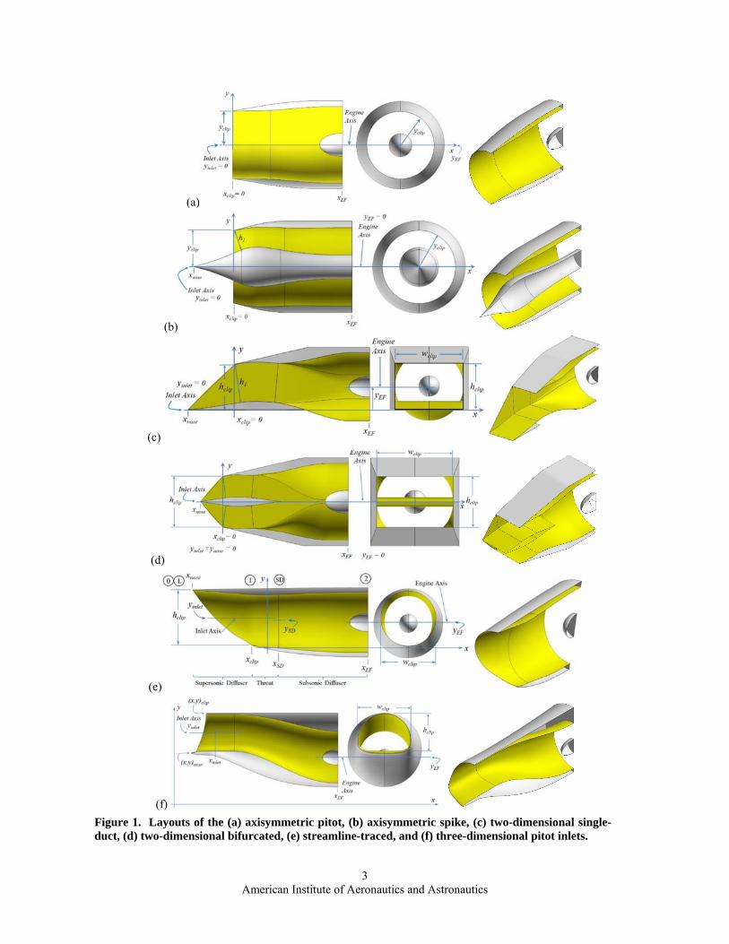
SUPIN models a set of inlet types that include the axisymmetric pitot inlet, three-dimensional pitot inlet, axisymmetric spike inlet, two-dimensional single-duct inlet, two-dimensional bifurcated inlet, and the streamline-traced inlet. The axisymmetric and two-dimensional inlets represent traditional inlets that can be designed and analyzed as baseline or reference inlets for inlet studies. The streamline-traced and three-dimensional pitot inlets provide more general capability for alternative inlet concepts. The use of a set of inlet types simplifies the design and analysis process by establishing the topology of the inlet based on the inlet type. All of the inlet types are created through simple planar or three-dimensional geometry constructs, which avoid the need for specialized computational geometry software. The inlets designed through SUPIN can serve as starting configurations for more advanced inlet optimization techniques. Figure 1 shows the six inlet types available within SUPIN.
B. Inlet Coordinate System
The inlets are defined with respect to an (x,y,z) Cartesian coordinate system with the positive x-coordinate in the general direction of the airflow. The inlet topology includes an inlet axis with coordinate yinlet, the axis of station SD with coordinates (x,y)SD, and the engine axis located at (x,y)EF. All of these coordinates are assumed to be positioned on the plane-of-symmetry of the inlet defined at z = 0.
C. Inlet Parts and Stations
SUPIN uses a one-dimensional representation of the flowpath through the inlet for the analysis of the aerodynamic performance. Stations are defined along the flowpath at which the flow properties are determined. The numeric stations conform to those of the Society of Automotive Engineers (SAE) Aerospace Standard 755.20
The freestream is designated as station 0 and require specification of the Mach number (M0) and altitude (h0). The standard atmosphere provides the corresponding thermodynamic properties (p0, T0). Alternatively, the freestream conditions can be directly specified.
Station L is the local station at the inflow ahead of the inlet. The flow conditions may change between stations 0 and L as the inlet streamtube washes over parts of the aircraft or wing ahead of the inlet. SUPIN does have a simple model for the approach flow that allows for change in Mach number and total pressure between stations 0 and L due to oblique or conical shocks and isentropic compression or expansion. The inflow to the inlet at station L is assumed to be uniform. It is also assumed that the inlet axis is aligned with the inflow, which means that the angle-of-attack and angle-of-sideslip for the inlet are zero. The flow conditions at station L establish the upstream aerodynamic boundary conditions for the inlet design and analysis problem.
Station 1 indicates the start of the internal ducting of the inlet. This station is also referred to as the cowl lip station. The character of the geometry of station 1 depends on the type of inlet. The two-dimensional, axisymmetric spike, and streamline-traced inlets contain an external supersonic diffuser extending between stations L and 1.
The engine-face is designated as station 2. SUPIN assumes that the engine face dimensions are specified. For a supersonic inlet, a common engine is the turbofan for which the engine face is circular and a spinner exists about the engine hub. The spinner is characterized by the hub-to-tip ratio indicating the diameter of the hub with respect to the diameter of the fan. The spinner is assumed axisymmetric with a conical, circular, or elliptical profile. SUPIN does have the option for an engine face defined by super-ellipses that can model an elliptical or near-rectangular engine face with or without a spinner. The flow conditions at the engine face are specified by the actual or corrected engine flow rate or the mass-averaged Mach number at the engine face. Thus, the engine face establishes the downstream aerodynamic and geometric boundary conditions for the inlet design and analysis problem.
American Institute of Aeronautics and Astronautics
3
(a)
(b)
(c)
(d)
(e)
(f)
Figure 1. Layouts of the (a) axisymmetric pitot, (b) axisymmetric spike, (c) two-dimensional single-duct, (d) two-dimensional bifurcated, (e) streamline-traced, and (f) three-dimensional pitot inlets.
American Institute of Aeronautics and Astronautics
4
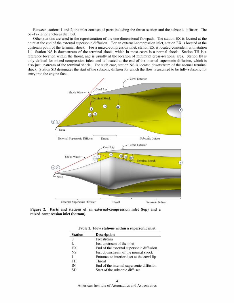
Between stations 1 and 2, the inlet consists of parts including the throat section and the subsonic diffuser. The cowl exterior encloses the inlet.
Other stations are used in the representation of the one-dimensional flowpath. The station EX is located at the point at the end of the external supersonic diffusion. For an external-compression inlet, station EX is located at the upstream point of the terminal shock. For a mixed-compression inlet, station EX is located coincident with station 1. Station NS is downstream of the terminal shock, which in most cases is a normal shock. Station TH is a reference location within the throat, and is usually at the location of minimum cross-sectional area. Station IN is only defined for mixed-compression inlets and is located at the end of the internal supersonic diffusion, which is also just upstream of the terminal shock. For such case, station NS is located downstream of the normal terminal shock. Station SD designates the start of the subsonic diffuser for which the flow is assumed to be fully subsonic for entry into the engine face.
Station Description 0 Freestream L Just upstream of the inlet EX End of the external supersonic diffusion NS Just downstream of the normal shock 1 Entrance to interior duct at the cowl lip TH Throat IN End of the internal supersonic diffusion SD Start of the subsonic diffuser
Table 1. Flow stations within a supersonic inlet.
Figure 2. Parts and stations of an external-compression inlet (top) and a mixed-compression inlet (bottom).

American Institute of Aeronautics and Astronautics
5
2 Engine face
III. SUPIN Design and Analysis Methodology and Usage This section describes some of the methodology of how SUPIN operates and models the key parts of the inlet.
A. SUPIN Usage and Files
SUPIN is a Fortran 95 computer code that reads in an ASCII input data file and writes out an ASCII output data file. The input data file contains a list of blocks that contain input factors that establish the geometry and flow specifications and tells SUPIN what is to be done. The output data file summarizes the geometry and aerodynamic performance of the inlet. SUPIN can also generate files of the inlet surface grids in Plot3D and stereo-lithography file (STL) formats.21 These files can be used for visualization of the inlet geometry and for the generation of grids for CFD analysis. SUPIN can also automatically generate planar and three-dimensional, multi-block, structured grids for use with CFD methods.
B. Design and Analysis Modes
SUPIN can operate in three design and analysis modes: 1) Geometry Mode, 2) Design Mode or 3) Analysis Mode. The Geometry Mode uses the values of the geometry input factors as specified in the input data file to create the geometry of the inlet. This requires that the set of values of the geometry factors completely define the inlet geometry. This mode does not calculate the aerodynamic performance of the inlet.
The Design Mode sizes the inlet and calculates the aerodynamic performance of the inlet. The sub-sections below will discuss the methodologies for computing the performance of each part of the inlet and sizing the inlet. The inlet sizing is primarily concerned with establishing the size of the capture area of the inlet.
The Analysis Mode creates the geometry of the inlet as in the Geometry Mode and then calculates the aerodynamic performance of the specified inlet geometry. As with the Geometry Mode, the set of values for the geometry factors must completely define the inlet geometry. As part of this geometry specification, the capture area must be specified in some manner. The Analysis Mode is intended to analyze the inlet for off-design Mach numbers and engine flow rate. This mode is still under development and is not currently fully functional.
C. External Supersonic Diffuser
The external supersonic diffuser establishes a system of shock and Mach waves for the deceleration and compression of the flow between stations L and 1, which is external to the internal ducting of the inlet. The axisymmetric spike inlet uses the spike for the external supersonic diffuser. The two-dimensional inlets use ramps. The axisymmetric spike and two-dimensional ramps result in an outward turning of the flow with respect to the inlet axis. The streamline-traced inlet uses the external streamline-traced surface and results in an inward-turning of the flow. All of these surfaces result in the contraction of the inlet streamtube cross-section, which results in the deceleration and compression.
A primary input factor for the design of the external supersonic diffuser is the Mach number desired at station 1. For the two-dimensional and axisymmetric spike inlets, station 1 is defined as the cross-section at the start of the internal ducting of the inlet that is perpendicular to the centerbody and intersects the cowl lip. For the two-dimensional inlets this cross-section is rectangular. For an axisymmetric inlet, this cross-section is co-annular. For an external-compression inlet, the normal terminal shock is assumed to be positioned at station 1. Station EX represents the flow on the upstream side of the terminal shock. The input factor is the value of the supersonic Mach number at station EX, MEX. A general rule is that MEX 1.3 to avoid separation of the centerbody boundary layer at its interaction with the normal terminal shock. The Mach number at station 1 would then be the subsonic Mach number calculated downstream of a normal shock. For a mixed-compression, two-dimensional or axisymmetric spike inlet, the input factor would also be the supersonic Mach number at station EX (MEX); however, since the terminal shock now is downstream within the throat, this Mach number may be larger, MEX 1.3, but yet it must be smaller than the inflow Mach number, MEX ML. The choice of the value of the input factor MEX depends on the desired balance of external and internal supersonic compression.
Another input factor for the external supersonic diffuser of the two-dimensional and axisymmetric spike inlets is the number of stages. A single-stage diffuser involves a single ramp or cone. SUPIN can model up to three stages with the option of an isentropic profile for the second stage of a three-stage diffuser. The design methodologies use oblique shock relations, conical flow solutions of the Taylor-Maccoll equations, and method of characteristics depending on the type of diffuser and number of stages, as appropriate. For the two-dimensional diffusers involving two or three ramps, an option exists to use the Oswatitsch criteria to establish the optimum ramp angles to minimize total pressure loss. For the axisymmetric spike inlet, the two and three-stage diffusers require specification of the
American Institute of Aeronautics and Astronautics
6
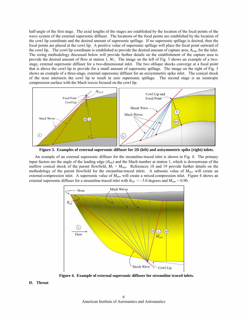
half-angle of the first stage. The axial lengths of the stages are established by the location of the focal points of the wave system of the external supersonic diffuser. The locations of the focal points are established by the location of the cowl lip coordinate and the desired amount of supersonic spillage. If no supersonic spillage is desired, then the focal points are placed at the cowl lip. A positive value of supersonic spillage will place the focal point outward of the cowl lip. The cowl lip coordinate is established to provide the desired amount of capture area, Acap, for the inlet. The sizing methodology discussed below will provide further details on the establishment of the capture area to provide the desired amount of flow at station 1, W1. The image on the left of Fig. 3 shows an example of a two-stage, external supersonic diffuser for a two-dimensional inlet. The two oblique shocks converge at a focal point that is above the cowl lip to provide for a small amount of supersonic spillage. The image on the right of Fig. 3 shows an example of a three-stage, external supersonic diffuser for an axisymmetric spike inlet. The conical shock of the nose intersects the cowl lip to result in zero supersonic spillage. The second stage is an isentropic compression surface with the Mach waves focused on the cowl lip.
Figure 3. Examples of external supersonic diffuser for 2D (left) and axisymmetric spike (right) inlets.
An example of an external supersonic diffuser for the streamline-traced inlet is shown in Fig. 4. The primary input factors are the angle of the leading edge (stle) and the Mach number at station 1, which is downstream of the outflow conical shock of the parent flowfield, M1 = Mstex. References 18 and 19 provide further details on the methodology of the parent flowfield for the streamline-traced inlets. A subsonic value of Mstex will create an external-compression inlet. A supersonic value of Mstex will create a mixed-compression inlet. Figure 4 shows an external supersonic diffuser for a streamline-traced inlet with stle = - 5.0 degrees and Mstex = 0.90.
Figure 4. Example of external supersonic diffuser for streamline traced inlets.
D. Throat

American Institute of Aeronautics and Astronautics
7
The throat section extends between stations 1 and SD. The intent of the throat is to perform any needed turning of the flow while decelerating the flow to obtain subsonic speeds at station SD. For an external-compression inlet, the terminal shock is usually designed to be located at or slightly ahead of station 1. For those conditions, the flow within the throat is subsonic. For the supercritical operation of an external-compression inlet, the terminal shock enters the forward portion of the throat to obtain flow continuity.
For a mixed-compression inlet, the forward portion of the throat section operates as an internal supersonic diffuser with a shock and Mach wave system that terminates with a normal terminal shock. The aft portion of the throat contains subsonic flow that feeds into the subsonic diffuser. Figure 5 shows a schematic for the design methodology within SUPIN for the throat of a mixed-compression inlet. The flow at station 1 is the outflow of the external supersonic diffuser. The angle of the cowl lip interior (cwlin) is specified such as to create an oblique cowl shock that intersects the centerbody at point (x,y)cbcs. The cowl shock properties are computed assuming a planar oblique shock. The centerbody maintains the same slope as the end of the external supersonic diffuser (cb1) up until point (x,y)cbcs to ensure that the centerbody does not create shock or Mach waves that would interfere with the cowl shock. The cowl interior downstream of the cowl lip likewise maintains the slope of the cowl lip inlet (cwlin) up to the point (x,y)cwmw so that the cowl interior does not create shock or Mach waves that may interfere with the cowl shock. Point (x,y)cwmw is defined by the Mach wave that passes through point (x,y)cbcs. Downstream of the Mach wave, it is assumed that any shock or Mach waves that are created are very weak and are not modeled. SUPIN does allow an input for the estimate of the total pressure loss in this region. The supersonic Mach number is decreased through a decrease in the cross-sectional area. An input factor is the desired Mach number at station TH. Between points (x,y)cbcs and (x,y)cbTX, the centerbody profile is modeled as a NURBS curve for which the initial slope is cb1 and the end slope is cbTX. The x-coordinates are defined by the specification of the length of the shoulder (Lcbsh). It is specified that ycbTX = ycbcs. The point (x,y)cbTH is determined as the point on the shoulder with zero slope. Station IN is the end of the internal supersonic diffusion and is on the upstream side of the terminal shock. Station IN is also coincident with station TX, which is the start of a “straight” section of the aft throat section that ends at station SD. The length of this section is defined by the input factor LTXSD. The area at the cross-section at station SD is established through specification of the area ratio between stations SD and TX, ASD/ATX.
Figure 5. Schematic for design of the throat of a mixed-compression inlet.
E. Subsonic Diffuser
The subsonic diffuser extends between stations SD and 2. The shaping of the subsonic diffuser surfaces involves a transition between the shapes of the cross-section at station SD to the cross-section at the engine face station 2. The axisymmetric inlets will have a circular cross-section at stations SD. The two-dimensional inlets will have rectangular cross-sections at station SD. The streamline-traced and three-dimensional pitot inlets have cross-sections defined by super-ellipses, which can vary from circular to near rectangular.22 Figure 6 shows examples of the two-dimensional single-duct, streamline-traced, and three-dimensional pitot inlets with the stations SD and 2 being identified and the shape of the subsonic diffuser being shown.
The axisymmetric and two-dimensional bifurcated inlets place the engine axis collinear with the inlet axis. The two-dimensional single-duct, streamline-traced, and three-dimensional pitot inlets allow the engine axis to be offset in the vertical direction from the inlet axis. This may be done to improve inlet performance. However, the relative placement of the inlet and engine axes could be specified as part of an inlet installation onto an aircraft, and so, would not be a design factor for the inlet design.
The length of the subsonic diffuser is a design factor. One approach is to calculate the length such as to provide a certain equivalent conical angle between stations SD and 2. A conical angle of about 3 degrees is considered a

American Institute of Aeronautics and Astronautics
8
reasonable value. Other approaches include directly specifying the length of the subsonic diffuser or specifying the length of the entire inlet and computing the length of the subsonic diffuser after subtracting the length of the external supersonic diffuser and the throat section.
Figure 6. Schematic for subsonic diffuser. (2D, STEX, 3D Pitot).
F. Inlet Total Pressure Recovery
The inlet total pressure recovery is determined by the product of the recoveries of the individual parts of the inlet,
(1)
The shock waves of the external supersonic diffuser introduce losses in the total pressure between stations L and EX, which can be computed through the oblique and normal shock equations and represented by the ratio ptEX/ptL. An empirical model is used within SUPIN to calculate the total pressure losses in the subsonic diffuser. It accounts for the area ratio between stations SD and 2, the length of the subsonic diffuser, and the amount of vertical offset between the inlet and engine axes.
G. Cowl Exterior and Cowl Drag
The cowl exterior encloses the inlet and provides a surface upon which the cowl drag can be estimated. The integration of an inlet with the aircraft has a large effect on the shape of the cowl exterior and the resulting drag; however, SUPIN provides a model to create a cowl exterior for the isolated inlet so that cowl drag can be calculated and compared to other isolated inlets designed under the same conditions.
The cowl exterior is created by sculpting a smooth or faceted surface from the leading edge and cowl lip to a downstream cross-section. Figure 7 shows examples of the cowl exterior geometry for the two-dimensional, axisymmetric spike, and the streamline-traced inlets.
For the axisymmetric inlets, the cowl exterior is axisymmetric and is created by establishing a profile and extruding the profile about the inlet axis. The profile starts at the cowl lip with a specified cowl lip exterior angle. The profile ends at a point located at the engine-face axial station with a radius set as a factor (Frcex) of the engine-face radius. The input factor Frcex is selected to provide the proper volume for inlet structure.
For two-dimensional inlets, the cowl exterior is a faceted surface that accounts for the rectangular shape of the capture aperture. At the top of the inlet, the forward surface is oriented according to the specified cowl lip exterior angle. On the side, the forward surface is oriented according to a specified cowl lip sidewall angle. The cowl exterior extends to the engine face with flat aft surfaces on the top and side. The aft surfaces are placed relative to the engine axis by a factor Frcex of the engine-face radius. If the engine axis is too far below the inlet axis, the top aft surface is placed above the cowl lip by the factor Frcex.
For the streamline-traced and three-dimensional pitot inlets, the cowl exterior is formed from a smooth surface defined by NURBS curves extending from the cowl lip to a downstream cross-section. The downstream cross-section is circular with a diameter that is specified as a factor Frcex of the engine-face diameter. The x-coordinate of the downstream station can be either specified or located at the engine-face position. The NURBS curve starts with a cowl lip exterior angle that varies about the circumference of the leading edge of the inlet. The distribution of the cowl lip exterior angles is determined as part of the design of the external supersonic diffuser. At the end of the NURBS curves, the exterior angle is in line with the engine axis.
SUPIN estimates the wave drag on the cowl exteriors. For the faceted cowl exterior of the two-dimensional inlets, the pressures on the forward-facing surfaces can be computed using oblique shock relations. For the axisymmetric and streamline-traced inlets, the pressures are computed using a compressible linearized equation methodology as described in Ref. 10.

American Institute of Aeronautics and Astronautics
9
H. Inlet Sizing
The inlet sizing occurs for the Design Mode and centers on determining the appropriate capture area (Acap), lengths, angles, and dimensions of the inlet. The capture area, Acap, is defined by the area of the forward projection of the highlight of the inlet as defined in part by the leading edges of the external supersonic diffuser. The sizing process involves an iteration in which the dimensions, flow rates, and total pressure losses through the inlet are adjusted until a converged solution is obtained. The Design Mode involves an assumption on the location of the terminal shock. For an external-compression inlet, the terminal shock is assumed to be situated at station 1. For a mixed-compression inlet, the terminal shock is assumed to be situated within the throat section upstream of station SD. The sizing iteration starts with an initial guess for the total pressure loss through the inlet (pt2/ptL), which is obtained from the MIL-STD recovery relation. From the specification of the engine flow rate input and any estimates for spillage or bleed, the flow rates at the various stations within the inlet can be evaluated. Using the capture flow rate value, the capture area can be calculated. With the capture area known, the cowl lip position is established. The geometry and performance of the external supersonic diffuser, throat, and subsonic diffuser can be determined and a new estimate of the inlet total pressure recovery (pt2/ptL) can be determined and the iteration can be repeated.
I. Porous Bleed
Porous bleed is used within supersonic inlets to remove a portion of the lower-momentum flow of the boundary layer. The remaining higher-momentum flow in the boundary layer is better able to withstand adverse pressure gradients, such as those present during shock wave / boundary layer interactions. SUPIN allows the specification of a porous bleed rate for the removal of flow within the throat region between stations TH and SD. The bleed rate is specified as the ratio of the reference capture flow rate. This removal of flow is accounted for within the inlet sizing iterations. Generally, the use of porous bleed will result in an inlet with a larger reference capture area since the bled flow is not delivered to the engine, but rather expelled overboard or used elsewhere within the propulsion system, such as for cooling. The larger capture area may have implications with respect to inlet total pressure recovery and cowl drag.
Since the specification of bleed changes the flow rate into the subsonic diffuser, the Mach number at station SD may be less than that of the inlet designed with no bleed. This may change the estimate of the total pressure loss through the subsonic diffuser. However, SUPIN does not model a change in total pressure recovery due to the removal of a portion of the lower-momentum flow of the boundary layer in the throat.
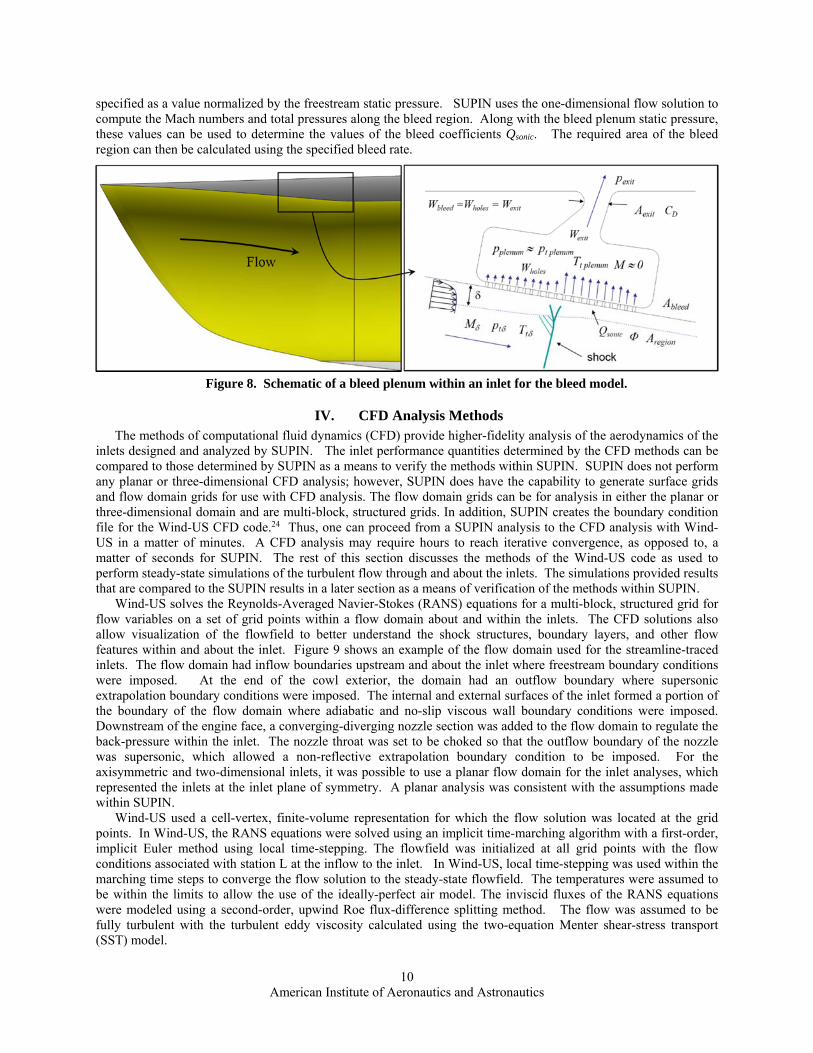
SUPIN does have the capability to size the porous bleed region within the throat that corresponds to the specified flow rate. The methodology uses the bleed model as described in Ref. 23 for porous bleed with holes with axes oriented 90-degrees to the inlet surface. Figure 8 shows a schematic that corresponds to the bleed model. At the bottom of the figure is the inlet core flow through the throat. A boundary layer forms on the throat surface. Figure 8 shows a shock wave interacting with the boundary layer. A porous bleed region containing an array of bleed holes leads to a bleed plenum of sufficient volume such that the bleed flow essentially stagnates. The plenum static pressure is a key property of the bleed plenum that controls the bleed flow rate. The bleed flow exits the bleed plenum through an exit with a specified exit area and discharge coefficient. The exit is typically choked to ensure that the exterior flow does not enter the bleed plenum. The bleed rate is modeled using an empirically-based relation for the bleed sonic coefficient, Qsonic. The input factors for the bleed sizing include the x-coordinates for the start and end of the bleed region, the porosity Φ of the bleed region, and the bleed plenum static pressure, which is
Figure 7. Examples of the cowl exteriors for the two-dimensional inlet (left), axisymmetric spike inlet (center), and the streamline-traced inlet (right).
American Institute of Aeronautics and Astronautics
10
specified as a value normalized by the freestream static pressure. SUPIN uses the one-dimensional flow solution to compute the Mach numbers and total pressures along the bleed region. Along with the bleed plenum static pressure, these values can be used to determine the values of the bleed coefficients Qsonic. The required area of the bleed region can then be calculated using the specified bleed rate.
Figure 8. Schematic of a bleed plenum within an inlet for the bleed model.
IV. CFD Analysis Methods The methods of computational fluid dynamics (CFD) provide higher-fidelity analysis of the aerodynamics of the
inlets designed and analyzed by SUPIN. The inlet performance quantities determined by the CFD methods can be compared to those determined by SUPIN as a means to verify the methods within SUPIN. SUPIN does not perform any planar or three-dimensional CFD analysis; however, SUPIN does have the capability to generate surface grids and flow domain grids for use with CFD analysis. The flow domain grids can be for analysis in either the planar or three-dimensional domain and are multi-block, structured grids. In addition, SUPIN creates the boundary condition file for the Wind-US CFD code.24 Thus, one can proceed from a SUPIN analysis to the CFD analysis with Wind-US in a matter of minutes. A CFD analysis may require hours to reach iterative convergence, as opposed to, a matter of seconds for SUPIN. The rest of this section discusses the methods of the Wind-US code as used to perform steady-state simulations of the turbulent flow through and about the inlets. The simulations provided results that are compared to the SUPIN results in a later section as a means of verification of the methods within SUPIN.
Wind-US solves the Reynolds-Averaged Navier-Stokes (RANS) equations for a multi-block, structured grid for flow variables on a set of grid points within a flow domain about and within the inlets. The CFD solutions also allow visualization of the flowfield to better understand the shock structures, boundary layers, and other flow features within and about the inlet. Figure 9 shows an example of the flow domain used for the streamline-traced inlets. The flow domain had inflow boundaries upstream and about the inlet where freestream boundary conditions were imposed. At the end of the cowl exterior, the domain had an outflow boundary where supersonic extrapolation boundary conditions were imposed. The internal and external surfaces of the inlet formed a portion of the boundary of the flow domain where adiabatic and no-slip viscous wall boundary conditions were imposed. Downstream of the engine face, a converging-diverging nozzle section was added to the flow domain to regulate the back-pressure within the inlet. The nozzle throat was set to be choked so that the outflow boundary of the nozzle was supersonic, which allowed a non-reflective extrapolation boundary condition to be imposed. For the axisymmetric and two-dimensional inlets, it was possible to use a planar flow domain for the inlet analyses, which represented the inlets at the inlet plane of symmetry. A planar analysis was consistent with the assumptions made within SUPIN.
Wind-US used a cell-vertex, finite-volume representation for which the flow solution was located at the grid points. In Wind-US, the RANS equations were solved using an implicit time-marching algorithm with a first-order, implicit Euler method using local time-stepping. The flowfield was initialized at all grid points with the flow conditions associated with station L at the inflow to the inlet. In Wind-US, local time-stepping was used within the marching time steps to converge the flow solution to the steady-state flowfield. The temperatures were assumed to be within the limits to allow the use of the ideally-perfect air model. The inviscid fluxes of the RANS equations were modeled using a second-order, upwind Roe flux-difference splitting method. The flow was assumed to be fully turbulent with the turbulent eddy viscosity calculated using the two-equation Menter shear-stress transport (SST) model.

American Institute of Aeronautics and Astronautics
11
Wind-US has the ability to model porous bleed using the model of Ref. 23. Porous bleed was modeled as a boundary condition in which the bleed rate was allowed to vary according to local flow conditions. The bleed boundary condition assumed the bleed flow entered a plenum and then was ejected into the exterior flow through a choked nozzle with a fixed throat area. However, Wind-US does not model the bleed exit flow within the cowl exterior grid. The primary inputs for the porous bleed model were the porosity of the bleed region and the area of the bleed exit nozzle.
V. Results The following sub-sections present some results of inlet design and analysis studies performed by SUPIN to
demonstrate some of the latest capabilities of SUPIN. Analyses using Wind-US were performed to check or verify some of the data obtained from SUPIN.
A. Streamline-Traced, External-Compression Inlets
A major focus of the development of SUPIN has been to create a computational tool for the design of streamline-traced, external-compression (STEX) inlets for speeds of about Mach 1.6. Reference 17 presented a methodology that was implemented into SUPIN for the design of STEX inlets. An inlet for Mach 1.6 freestream was designed and analyzed using methods of CFD. The performance of the STEX inlet was compared to the performance of an axisymmetric spike inlet designed using the same conditions. It was shown that the STEX inlet at the critical operating condition had a total pressure recovery of 0.948 compared to a recovery of 0.973 for the axisymmetric spike inlet. The total pressure distortion for the STEX inlet was of concern due to low-momentum flow that developed at the top of the subsonic diffuser. However, the STEX inlet had a wave drag coefficient that was only 17% of the wave drag coefficient of the axisymmetric spike inlet. The lower wave drag of the STEX inlet was due to lower external cowl angles. This also resulted in less pressure disturbances about the cowl exterior for the STEX inlet compared to the axisymmetric spike inlet. Less pressure disturbances likely lead to less sonic boom disturbances away from the inlet.
A change in the design methodology for the STEX inlet was introduced in Ref. 18, which discussed a novel parent flowfield for the streamline tracing that contained the leading edge oblique shock and the outflow conical shock within the analytic flowfield. This methodology was summarized in the sub-section above discussing the external supersonic diffuser for the streamline-traced inlets. Reference 19 presented the results of design studies using this new design methodology along with the study of several factors regarding the displacement and angle of the subsonic cowl lip and the position of the engine face relative to the inlet axis. The design studies were able to produce a STEX inlet with a total pressure recovery at the critical condition of 0.953 compared to a recovery of
Figure 9. Flow domain and boundary conditions for CFD analysis.

American Institute of Aeronautics and Astronautics
12
0.948 of the earlier STEX inlet. The new STEX inlet also had less spillage. The studies also examined the effect of porous bleed. With a 1% bleed, the recovery at the critical condition increased to 0.965.
The design methodology for the STEX inlet was modified to use a zero angle for the subsonic cowl lip and an axisymmetric subsonic diffuser. The tracing curve for the streamline tracing was constrained to be circular to allow for an axisymmetric subsonic diffuser. Figure 10 shows images of a STEX inlet for Mach 1.6 designed using the current methodology. As can be seen, the inlet leading edge has a scarfing. The bottom segment of the leading edge is the subsonic cowl lip and shows a displacement of the subsonic cowl lip downstream by a distance of 0.20 of the engine-face diameter. This displacement or “cut-out” allows for subsonic spillage, which was shown in Ref. 18 to be important for smooth variation of the shock system over the variation of the inlet flow rate. The STEX inlet of Fig. 10 at Mach 1.6 resulted in a total pressure recovery of 0.953 at the critical condition. This performance is comparable to that of the STEX inlet of Ref. 18. Thus, it may be concluded that the angle of the subsonic cowl lip and the shape of the subsonic diffuser have little effect on the total pressure recovery. The most influential factor seems to be the amount of axial displacement of the subsonic cowl lip in creating the “cut-out”. A value between 0.15 and 0.20 of the engine-face diameter seems to be the ideal value. A value of 0.15 resulted in a 1.0% spillage, while a value of 0.20 resulted in a 1.9% spillage.
Figure 11 shows Mach number contours on the symmetry plane for the current STEX inlet at Mach 1.6 for inlet
flows at the sub-critical, critical, and super-critical conditions. The center image at the critical condition shows the main features of the flowfield. At the leading edge, an oblique shock is formed. Along the external supersonic diffuser, Mach lines form to compress and decelerate the supersonic flow. The terminal shock forms about the subsonic cowl lip and extends to the shoulder at the end of the external supersonic diffuser. The flow becomes subsonic within the throat section and the flow enters the subsonic diffuser. A boundary layer at the top of the subsonic diffuser thickens and a low-momentum region increases toward the engine face.
Figure 12 presents the characteristic “cane” curves for the STEX inlet with comparison to the curves for the axisymmetric spike inlet and the STEX inlets of Refs. 17 and 18. As mentioned earlier, all three STEX inlets obtained a peak total pressure recovery at the critical condition of 0.953. The three STEX inlets vary in the amount of spillage as indicated by the different horizontal positions of the three cane curves. The three labels “A”, “B”, and “C” on the characteristic cane curve of the STEX inlet correspond to the sub-critical, critical, and super-critical operating conditions as shown in Fig. 11.
B. Inlet Design with Porous Bleed
SUPIN can design inlets with a specified bleed rate within the throat. Bleed is used to reduce the extent of low-momentum portions of the boundary layer, which is of benefit when the boundary layer involves interactions with shock waves or flows over surfaces with curvature. Both flow features can result in boundary layer separation with resulting decrease in total pressure recovery and increased total pressure distortion at the engine face. SUPIN can size the inlet for a specified bleed rate as specified as a ratio with respect to the capture flow rate.
Figure 11. Mach number contours on the symmetry plane for the Mach 1.6 streamline-traced, external-compression inlet designed for Mach 1.6 at sub-critical (left), critical (center), and super-critical (right) conditions.
Figure 10. Streamline-Traced, External-Compression inlet designed for Mach 1.6.

American Institute of Aeronautics and Astronautics
13
SUPIN was applied to design a STEX inlet with a 1% bleed rate. The effect of bleed is to increase the capture
area of the inlet. The STEX inlet with no bleed had a capture area of 5.931 ft2 while the STEX inlet with 1% bleed had a capture area of 6.087 ft2. The STEX inlet with bleed captures more flow since some of the captured flow is bled off rather than ingested by the engine. The Mach number at the start of the subsonic diffuser for the STEX inlet with bleed is 0.829, which is lower than that of the Mach 0.864 of the STEX inlet with no bleed. The result is a shorter subsonic diffuser and lower total pressure loss for the STEX inlet with no bleed. The inlet total pressure recovery of the STEX inlet with bleed is 0.977 compared to 0.961 for the STEX inlet with no bleed.
CFD simulations were performed for the STEX inlet with 1% bleed. A porous bleed region was applied at the shoulder with the circumferential extent of the bleed region being about 210 degrees centered about the top of the throat surface. The image on the left of Fig. 13 shows the bleed region. The Wind-US porous bleed boundary condition for 90-degree bleed holes was used with a porosity of Φ = 0.40. The bleed rate was specified at 1.0% of the captured flow rate and the plenum pressure was iterated to match the specified bleed rate. Figure 12 shows the characteristic “cane” curve for the STEX inlet with 1.0% porous bleed as obtained from the CFD simulations. Figure 13 shows the Mach number contours on the symmetry plane for the flow solution at the critical inlet operating point. This point is labeled as “D” on the characteristic curve of Fig. 12. The effect of the bleed is to reduce the thickness of the boundary layer along the top of the subsonic diffuser. This helped to increase the total pressure recovery by removal of some of the low-momentum flow in the boundary layer.
Figure 13. Mach number contours on the symmetry plane for the Mach 1.6 streamline-traced, external-compression inlet with 1% porous bleed at the shoulder.
Figure 12. Characteristic “cane” curve for the Mach 1.6 streamline-traced, external-compression inlet.

American Institute of Aeronautics and Astronautics
14

American Institute of Aeronautics and Astronautics
15
C. Mixed-Compression Inlet
SUPIN was used to design a mixed-compression, axisymmetric spike inlet for Mach 2.5. The freestream altitude was 40,000 feet. The engine face had a diameter of 3.0 feet and the hub at the engine face had a hub-to-tip ratio of 0.30. The engine corrected flow rate for the design corresponded to an engine-face Mach number of 0.45. The external supersonic diffuser was specified to have a mass-averaged Mach number at station EX/1 of Mach 2.0. The throat was specified to perform internal supersonic diffusion with a cowl lip interior angle of 5.0 degrees and a Mach number downstream of the shoulder at station IN of Mach 1.30. The aft part of the throat centerbody was specified to have a length of 0.5 feet and a slope of -15.0 degrees.
SUPIN designed an inlet with a capture aperture diameter of 1.519 feet and a length of 11.605 feet, which is 3.116 times the engine-face diameter. The split of supersonic compression resulted in 37% of external compression and 63% of internal supersonic compression. The total pressure recovery at the engine face obtained from SUPIN was 0.930 with zero supersonic spillage or full inlet operation.
Wind-US was used to simulate the inviscid, planar flowfield to compare to the SUPIN flowfield. Figure 14 shows the geometry of the mixed-compression, axisymmetric-spike inlet along with the Mach number contours on an axisymmetric plane. The conical shock wave and Mach waves of the external supersonic diffuser focus onto the cowl lip. An internal cowl shock forms at the cowl lip and intersects the centerbody just upstream of the shoulder. Shock and Mach waves within the throat cross as part of the internal supersonic compression of the throat region. A normal terminal shock is located downstream of the shoulder with subsonic flow downstream of the terminal shock. A mass-averaged integration of the flowfield at the engine face yields a total pressure recovery of 0.936 with a Mach number of 0.450.
The current capability to design and analyze mixed-compression inlets is still being developed and tested for two-dimensional and streamline-traced inlets. The goal is to be able to design and analyze inlets up to freestream speeds of Mach 4.0. Other methods for tailoring the shock and Mach waves of the internal supersonic compression, such as method-of-characteristics, are being explored.
Figure 14. Mixed-compression, axisymmetric spike inlet for Mach 2.5 with Mach number contours.
VI. Summary and Conclusions
SUPIN is a computational tool with capabilities for the design and analysis of supersonic inlets. SUPIN can design inlets through sizing and estimation of the inlet performance as measured by the flow rates, total pressure recovery, and drag. SUPIN is under active development to improve and verify existing capabilities and provide for extended capabilities, such as to compute off-design performance associated with off-design Mach numbers and engine flow rates.
Acknowledgments
The author would like to acknowledge the support of the Commercial Supersonic Technology Project of the NASA Advanced Air Vehicles Program.

American Institute of Aeronautics and Astronautics
16
References
1. Ames Research Staff, "Equations, Tables, and Charts for Compressible Flow", NACA Report 1135, 1953.
2. Moeckel, W. E., "Approximate Methods for Predicting Form and Location of Detached Shock Waves Ahead of Plane or Axially Symmetric Bodies", NACA TN 1921, 1949.
3. Henry, J. R., Wood, C. C., and Wilbur, S. W., "Summary of Subsonic-Diffuser Data", NACA RM L56F05, 1956.
4. Seddon, J. and E.L. Goldsmith, Intake Aerodynamics, AIAA Education Series, New York, 1985.
5. Seddon, J. and E.L. Goldsmith, editors, Practical Intake Aerodynamic Design, AIAA Education Series, New York, 1993.
6. Mahoney, J.J., Inlets for Supersonic Missiles, AIAA Education Series, Washington, DC, 1990.
7. Anderson, J.D., Jr., Modern Compressible Flow, McGraw-Hill Book Company, New York, 1982.
8. Tindell, R. and Tamplin, G., “An Inlet System Installed Performance Prediction Program using Simplified Modeling,” AIAA-1983-1167, June 1983.
9. Haas, M., Elmquist, R.A., Sobel, D.R., “The NIDA Code: A New Tool for Supersonic Inlet Design and Analysis,” JANNAF Propulsion Meeting, November 1993.
10. Barnhart, P.J., “IPAC – Inlet Performance Analysis Code,” NASA CR-204130, July 1997.
11. Sorensen, V.L., “Computer Program for Calculating Flow Fields in Supersonic Inlets,” NASA TN D-2897, July 1965.
12. Anderson, B.H., “Design of Supersonic Inlets by a Computer Program Incorporating the Method of Characteristics,” NASA TN D-4960, January 1969.
13. Varner, M.O., Martindale, W.R., Phares, W.J., Kneile, K.R., and Adams Jr., J.C., “Large Perturbation Flow Field Analysis and Simulation for Supersonic Inlets - Final Report,” NASA CR 174576, September 1984.
14. Slater, J.W., Davis, D.O., Sanders, B.W., and Weir, L.J., “Role of CFD in the Aerodynamic Design and Analysis of the Parametric Inlet,” ISABE–2005–1168, 2005.
15. Garzon, G.A., “Use of a Translating Cowl on a SSBJ for Improved Takeoff Performance,” AIAA-2007-0025, January 2007.
16. Slater, J.W., “Design and Analysis Tool for External-Compression Supersonic Inlets,” AIAA-2012-0016, January 2012.
17. Slater, J.W., “Methodology for the Design of Streamline-Traced, External-Compression Inlets,” AIAA-2014-3593, July 2014.
18. Otto, S.E, C.J. Trefny, and J.W. Slater, “Inward-Turning Streamline-Traced Inlet Design Method for Low-Boom, Low-Drag Applications,” AIAA-2015-3593, July 2015.
19. Slater, J.W., “Enhanced Performance of Streamline-Traced External-Compression Supersonic Inlets,” ISABE-2015-22049, October 2015.
20. SAE, Aerospace Standard (AS) 755, “Aircraft Propulsion System Performance Station Designation and Nomenclature,” December 1997.
21. Walatka, P.P., Buning, P.G., Pierce, L., and Elson, P.A., “PLOT3D User’s Manual,” NASA-TM-101067, March 1990.
22. Koncsek, J. L., "An Approach to Conformal Inlet Diffuser Design for Integrated Propulsion Systems," AIAA-1981-1395, July 1981.
23. Slater, J.W., “Improvement in Modeling 90-degree Bleed Holes for Supersonic Inlets,” AIAA Journal of Propulsion and Power, Vol. 28, No. 4, pp 773-781. July-August 2012.
24. Mani, M., Cary, A., and Ramakrishnan, S., “A Structured and Hybrid-Unstructured Grid Euler and Navier-Stokes Solver for General Geometry,” AIAA–2004–0524, January 2004.