
Supervision and control prototyping for an engine exhaust gas heat ...
8
Supervision and control prototyping for an engine exhaust gas heat recovery system based on a steam Rankine cycle Paolino Tona, Johan Peralez, Antonio Sciarretta To cite this version: Paolino Tona, Johan Peralez, Antonio Sciarretta. Supervision and control prototyping for an engine exhaust gas heat recovery system based on a steam Rankine cycle. 2012 IEEE/ASME International Conference on Advanced Intelligent Mechatronics (AIM), Jul 2012, Kaohsiung, Taiwan. pp.695 - 701, 2012, . HAL Id: hal-00874321 https://hal-ifp.archives-ouvertes.fr/hal-00874321 Submitted on 17 Oct 2013 HAL is a multi-disciplinary open access archive for the deposit and dissemination of sci- entific research documents, whether they are pub- lished or not. The documents may come from teaching and research institutions in France or abroad, or from public or private research centers. L’archive ouverte pluridisciplinaire HAL, est destin´ ee au d´ epˆ ot et ` a la diffusion de documents scientifiques de niveau recherche, publi´ es ou non, ´ emanant des ´ etablissements d’enseignement et de recherche fran¸cais ou ´ etrangers, des laboratoires publics ou priv´ es.
Transcript of Supervision and control prototyping for an engine exhaust gas heat ...
Supervision and control prototyping for an engine
exhaust gas heat recovery system based on a steam
Rankine cycle
Paolino Tona, Johan Peralez, Antonio Sciarretta
To cite this version:
Paolino Tona, Johan Peralez, Antonio Sciarretta. Supervision and control prototyping for anengine exhaust gas heat recovery system based on a steam Rankine cycle. 2012 IEEE/ASMEInternational Conference on Advanced Intelligent Mechatronics (AIM), Jul 2012, Kaohsiung,Taiwan. pp.695 - 701, 2012, .
HAL Id: hal-00874321
https://hal-ifp.archives-ouvertes.fr/hal-00874321
Submitted on 17 Oct 2013
HAL is a multi-disciplinary open accessarchive for the deposit and dissemination of sci-entific research documents, whether they are pub-lished or not. The documents may come fromteaching and research institutions in France orabroad, or from public or private research centers.
L’archive ouverte pluridisciplinaire HAL, estdestinee au depot et a la diffusion de documentsscientifiques de niveau recherche, publies ou non,emanant des etablissements d’enseignement et derecherche francais ou etrangers, des laboratoirespublics ou prives.

Supervision and control prototyping for an engine exhaust gasheat recovery system based on a steam Rankine cycle
Paolino Tona, Johan Peralez and Antonio Sciarretta1
Abstract— Rankine-cycle waste heat recovery systemsfor automotive applications have been the focus of intensiveresearch in recent years, as they seem to offer considerablepotential for fuel consumption reduction. Because of thehighly transient conditions they are subject to, controlplays a fundamental role to enable viability and efficiencyof those systems. Yet, surprising little research has beendevoted to this topic.
This paper illustrates the design of a practical supervi-sion and control system for a pilot Rankine steam processfor exhaust gas heat recovery from a spark-ignition engine.The proposed control strategy for power production fo-cuses more on ensuring continuity of operation than on thepursuit of optimality. The resulting decentralized controlsystem is implemented via two anti-wind up controllerswith feedforward action.
Performance has been assessed in simulation on amotorway driving cycle using real engine exhaust data.Despite very transient exhaust gas conditions, we showthat the expander can produce power throughout the cycle,avoiding start-stop procedures, which would greatly reducethe global efficiency.
I. INTRODUCTION
About 30% of the energy produced by internal com-bustion engines (ICE) is released as heat to the atmo-sphere, through the exhaust gases. Though only a smallfraction of it can be converted into high-quality, usableenergy (exergy, in thermodynamic terms), a potentialexists for recovering wasted heat in order to reduce fuelconsumption in ICE-powered vehicles. Among the pos-sible heat recovery solutions, turbo-compound is nowa-days a standard technology for Diesel engines. Othersolutions, involving thermoelectricity or thermodynamiccycles, have also been investigated during the last fewyears.
More particularly, waste heat recovery (WHR) sys-tems based on the Rankine thermodynamic cycle havebeen the focus of intensive research for road transporta-tion applications. To mention a few examples, BMW([1], [2]), Honda ([3], [4]) and Ford [5] have recently
1P. Tona, J. Peralez and A. Sciarretta are with theControl, Signal and System Department at IFP EnergiesNouvelles, France {paolino.tona, johan.peralez,antonio.sciarretta}@ifpen.fr
worked on this topic for cars, Cummins [6], Caterpillar[7], Daimler Trucks [8] and Volvo [9] for trucks. Theinterest of manufacturers is justified by announced re-ductions in fuel consumption ranging from 5 to 10%,depending on the system and the driving cycle.
However, despite the development of several Rankinesystem prototypes for road transport, with few of themeven making their way to demo vehicles, it is stillunclear how viable and efficient these systems can be inreal-world applications. In practice, these systems oftenstruggle to attain satisfactory performance over a broadrange of (transient) operating conditions.
One of the reasons why Rankine systems do not yetlive up to their promises, is that they are most oftendesigned for nominal performance in steady state, with-out taking into account the (highly) transient conditionsthey are subjected to when plugged to a powertrain. Thequestion of how to control (or even, how controllableis) the resulting system is seldom raised at early stages.Eventually, if the heat recovery system has to be shutdown too often and/or it takes too long to attain powerproduction conditions, expected gains will vanish.
Control plays a fundamental role to enable viabil-ity and efficiency of Rankine-cycle WHR systems forautomotive applications. Despite this, surprising littleresearch has been devoted to this topic.
This paper illustrates the design of a supervision andcontrol system for a pilot Rankine steam process forexhaust gas heat recovery from a spark-ignition (SI)engine, from a prototyping point of view. This meansthat the supervision and control system is developed andvalidated in a realist framework to make it ready fortesting on the experimental bench.
Section II presents the context of Rankine-based wasteheat recovery for automotive applications and the stateof the art on the control of such systems. Section III de-scribes the Rankine steam process under consideration.Section IV gives a brief overview on the models usedfor control prototyping while section V describes morethoroughly the supervision and control system. SectionVI describes the co-simulation framework and providessome illustrative simulation results. A few concluding

remarks, putting this work in perspective, end the paper.
II. CONTEXT AND STATE OF THE ART
A. Rankine systems for automotive applications
The Rankine cycle is a thermodynamic cycle whichconverts heat into work. An external heat source suppliesheat to a working fluid which circulates in a closed loop,via a heat exchanger (or a series of heat exchangers).Expansion of vaporized fluid (generally via a turbine)produces mechanical power. Vapor is then convertedinto liquid in a condenser which transfers heat to anexternal cold sink. A pump circulates the fluid at therequired pressure. Most power plants in the world aresteam powered and use this kind of cycle to generatepower.
Typically, Rankine-based heat recovery systems forautomotive applications have the layout shown in Fig-ure 1.
To be viable, these systems must be lightweight andcompact. Thus, heating, vaporization and superheatingof the fluid usually take place in a single heat exchanger,the evaporator. The evaporator, whose hot gas inlet isusually “plugged” on the exhaust line, downstream ofthe after-treatment system, must be designed to interfereas little as possible with engine operation (low pressuredrop). With regard to the condenser, the thermal capacityof the external heat sink will necessarily be (very)limited compared to that of a power plant.
The expander can be a positive-displacement device(reciprocating engine, scroll expander) or a turbine. Itis arguably the most difficult component to design, as itmust have high efficiency over a very broad operatingrange.
In most cases, Rankine systems for automotive ap-plications are designed to produce electricity via agenerator connected to the auxiliary network and/or anenergy storage system, although produced mechanical
Fig. 1. Rankine WHR system layout for automotive applications
power can be used directly via a mechanical connectionto the transmission (as in [9]).
Practical Rankine systems for waste heat recoveryfrom Diesel engines use organic, high molecular massfluids, such as hydrofluorocarbons (HFCs), which boilat lower temperatures than water. Water can still be usedas a working fluid to recover heat from the exhaustgas of spark-ignition engines, whose temperatures areconsiderably higher.
B. Control issues
In power plants, the role of the control system ismainly to regulate the power delivered by the turbine-generator to a power grid, while guaranteeing the bestefficiency conditions (maximizing heat transfer in theevaporator and using the turbine on optimal operatingpoints). The first objective can be achieved by control-ling the enthalpy flow rate from the hot source, whichessentially means controlling the mass flow rate of fuelto be burnt in the plant. The second objective can beapproached by “moving” the corner points (see Figure 4in the following) of the thermodynamic cycle (adaptingthe mass flow rate of working fluid and, wheneverpossible, expander speed).
Control is not trivial because of the multivariableand coupled nature of the process, and becomes evenmore difficult in the waste heat recovery case, since theenthalpy flow rate from the hot source depends on thecurrent use of the engine: it cannot be directly manip-ulated, but acts instead as a (measured) disturbance tothe control system. Disturbances to the control systemare also the cooling capacity of the heat sink, whichmight be partially controllable but is always limited, andthe power request from the vehicle electrical network,whose handling may be more or less difficult thanin the power plant case, depending on the smoothingcapacity of the interface with the network. Additionaldifficulties arise from the safe operating range of eachcomponent, which can be quite limited in terms ofadmissible temperatures, pressures and vapor qualities.Last but not least, available on-board measurements andcomputational power are also limited.
The control system will benefit from more or lesscontrol authority depending on the architecture of theunderlying Rankine process. Within the available de-grees of freedom, only a well-designed control strategywill allow the WHR system to develop its full potentialin real-world conditions.
C. State of the art
During the last few years, many research papershave been published on the topic of Rankine-based

engine waste heat recovery systems for transportationapplications. Most of them are dedicated to design issues(structure, components, working fluid) and to potentialassessment (good examples are [10], [4], [1], [11],[12]). Papers on control issues are, on the other hand,surprisingly few in number.
The most detailed paper we have found in our lit-erature review is [3], from Honda, where the authorspresent a Rankine system for waste heat recovery froma SI engine in a hybrid powertrain, using water asworking fluid and a positive-displacement expander toproduce electric power (via an integrated generator).Experimental results are provided for a decentralizedcontrol system composed of two proportional controllerswith feedforward. Pump speed and expander speed areused as actuators to control respectively temperature andpressure of steam at evaporator outlet.
A more generic overview of control issues forRankine-based WHR systems in vehicles is given in[13]. The impact of architecture on control authorityis underlined, as well as the potential of using certainphysical variables, such as system pressure, as actuatorsto improve system efficiency or energy recovery.
More recently, in [14], a complete start-up and shut-down procedure is described for a Rankine cycle systemwith ethanol as working fluid, for heavy-duty applica-tions. The test bench is then operated manually, adjust-ing pump speed to sweep different operating points ofthe system.
On the more general topic of Organic Rankine Cycles(ORC) for waste heat recovery operating with variableheat sources (not necessarily for transport applications),[15] covers dynamic modeling and control of an ORCsystem with R234fa as a working fluid. Evaporatingtemperature and superheat1 are controlled by two PIcontrollers, using respectively expander speed and pumpspeed as actuators. Simulation results are given, whichshow acceptable performance. However, hot source vari-ations used for simulation are much slower than thoseobserved at the exhaust of an automotive engine, espe-cially in terms of mass flow rate.
A somewhat richer literature exists on dynamic mod-eling and control of vapor compression cycles, the“reverse” of Rankine cycle, for air conditioning systems(see, for instance, [16] and the numerous papers ofthe Alleyne Research Group [17], [18], [19]). Moreparticularly, in [18], a solid approach is presented forboth modeling, with the use of simplified (moving-boundary) heat exchanger models, and control design,
1Superheat is the number of degrees by which the temperature ofsuperheated vapor exceeds the saturation temperature of the fluid.
with the development of control systems of increasingcomplexity (from decentralized PI-based control to mul-tivariable H∞ synthesis) to improve performance.
III. SYSTEM DESCRIPTIONThe system under consideration is a pilot Rankine
steam process for recovering waste heat from a SIengine. Figure 2 shows its main components:• volumetric pump;• cross-flow evaporator;• positive-displacement expander;• steam - liquid condenser;• tank (separator);• evaporator by-pass valve;• expander by-pass valve;The latter two components are there to provide more
degrees of freedom to control system operation. Forinstance, expander by-pass will be kept open as longas fluid condition at evaporator outlet are not safe forthe expander. Whereas evaporator by-pass will be keptopen as long as exhaust gas conditions are not favorableto heat recovery. With proportional by-pass valves, evenmore flexibility is provided to the control system.
Power produced by the positive-displacement ex-pander is used by a generator (not shown) to produceelectricity. Generator load can be controlled to allowexpander speed adjustment.
With this set-up, the main actuators are:• evaporator by-pass valve opening setpoint V oSP
evap;• expander by-pass valve opening setpoint V oSP
exp;• pump rotational speed setpoint NSP
pump (or, indi-rectly, water mass flow rate at pump outlet mSP
pump);• expander rotational speed setpoint NSP
exp;Pressure and temperature measurements are available
at the inlet and outlet of each component. Controlledvariables must be chosen among those measurements orcombinations thereof.
Fig. 2. Layout of Rankine steam process under consideration
IV. MODELING
A reference simulator has been developed for theRankine system above, using TIL 2.1 [20], a Modelica[21] library for steady-state and transient simulationof thermodynamic systems. Blocks implementing finite-volume (FV) models are used for the two heat exchang-ers, to describe accurately their two-phase behavior. Forcontrol prototyping purposes, another, simpler simulatorhas been developped, replacing finite-volume modelswith moving-boundary (MB) models ([22], [23]). InMB models, separate control volumes (zones) for two-phase and single phase fluid flow are defined, whoseboundaries change dynamically, and zone lengths be-come dynamical states.
If well-coded, MB models allow the developmentof faster and more robust simulator while retainingaccuracy. In Figure 3, results from the two simulators arecompared, with a given exhaust enthalpy flow Hexh, interms of superheat Shevap and pressure pevap of water atevaporator outlet, with respect to expander speed Npump
and pump mass-flow mpump.For reasons of space, the resulting differential-
algebraic system of equations (with 19 dynamical states)is not presented in this paper. The modeling approachfor each component is similar to that adopted in [23].
V. CONTROL SYSTEM
A. Overall structure
The control system, coded in Simulink, has a basesampling period of 20ms, allowing proper filtering andcontroller discretization. It is composed of four mainmodules: Sensors, Actuators, Supervisor andControl. The Sensors module is used to filter
Fig. 3. Comparison between FV and MB models. Closed-loop controlis switched on at t = 250s.
available measurements and compute or estimate ther-modynamic variables (enthalpy flow rate, superheat, sub-cooling) from those measurements. The Actuatorsmodule translates high-level commands to appropriateactuator setpoints. The Supervisor module imple-ments safeties and manages the following system modes:• Stop: exhaust gas (not hot enough) bypasses the
evaporator;• Cold idle: exhaust gas enters the evaporator while
pump circulates fluid (Shevap not yet positive);• Hot idle: fluid conditions at evaporator outlet per-
mitting the use of the expander are targeted;• Expander start-up: expander bypass is closed and
expander speed controlled;• Power-production: nominal mode, in which the
system should stay as much as possible;• Expander shut-down: expander bypass is open
and expander speed is brought to zero.Each mode activates a specific (open-loop or closed-loop) control strategy implemented in the Controlmodule. Only the strategy for the power-productionmode, the most important and complex to control, isdetailed in the following.
B. Control strategy for power-production modeAs for any other heat recovery system, the control
strategy must meet two core requirements: maximizingefficiency (i.e. recovering as much energy as possible)and ensuring component safety. In the power-productionmode defined above, the pump and the expander, withtheir speed servos, provide two degrees of freedom tocontrol two key variables : pressure pevap and superheatShevap at evaporator outlet.
The cycle efficiency is defined as the ratio betweenthe net work output (i.e. the work produced by theexpander minus the work required by the pump, thelatter being practically negligible), and the heat suppliedby the exhaust gas to the working fluid.
The cycle representation on the p − h diagram ofFigure 4 shows that specific enthalpy at expander outlet(h2), should be as low as possible. But if the saturatedvapor line is crossed, there will be liquid water in theexpander. The tolerable value for vapor quality xexp atpoint 2, depends on the expander technology. In ourcase, we will try to maintain xexp close to unity, acompromise between efficiency and expander protection.
At expander inlet (that is, at evaporator oulet), for agiven fluid pressure, there is one superheat value thatyields unity vapor quality at expander outlet. This valuewill be used as a reference Shref
evap for our controller.As to the evaporator outlet pressure setpoint, steady-
state analysis shows that there exists an optimal value

Fig. 4. Rankine cycle on water p− h diagram
poptevap for cycle efficiency. poptevap depends in particularon exhaust gas temperature and mass flow rate. It couldbe tempting to use this optimal value as a setpoint, asproposed in [3] and [15]). In our opinion this approach,based on steady-state considerations, is questionablebecause
1) highly-transient external conditions imposed byreal usage imply that the system never reaches anequilibrium state;
2) system response times to control actions vary sig-nificantly with operating conditions (due to strongnon-linearities of the evaporator, as emphasized by[18]).
In fact, in the presence of a fast-varying hot source,trying to ensure the tracking of an optimal pressuretrajectory at evaporator outlet affects the performanceof superheat control, and may thus endanger the system.If, eventually, superheat Shevap could not be regulatedto a safe value, expander would be shut down, and theoverall performance would be affected.
This is why we prefer to free Pevap from any opti-mality constraint and make it track instead a referenceP refevap computed to help superheat control perform better.
The objective becomes to control superheat Shevap aswell as possible, while keeping Pevap in the permissibleoperating range for the expander (between 5 and 15 barin our case).
To do this, let us represent in a p − Sh diagram(Figure 5) the characteristic curve of the isentropicefficiency of the expander, connecting points 1 and 2of the p − h diagram of Figure 4. We have seen thatthe superheat reference Shref
evap must lie on the curve
Fig. 5. Reference generation using the p − Sh equivalent of theexpander isentropic efficiency characteristic
to ensure unity vapor quality at point 2. Likewise, thepressure reference prefevap is taken on this curve in orderto form the reference pair (prefevap, Shref
evap), with Pmin <prefevap < Pmax, to comply with the expander operatingrange. The interest of using pressure in superheat controlis explained by the physical link between pressure andevaporation temperature: decreasing the pressure makesthe evaporation temperature decrease and therefore thesuperheat increase.
Note that the cycle of Figure 4 and the reference gen-eration strategy of Figure 5 are obtained based on sev-eral simplifying assumptions, which include neglectingpressure drops in the heat exchangers, neglecting under-expansion and over-expansion losses in the expander andconsidering isentropic efficiency speed-independent. Thelatter may prove to be a strong assumption for positive-displacement expanders.
C. Implementation in a decentralized control scheme
Implementing the strategy above requires designinga controller for a two-input two-output (TITO) system.A coupling analysis on the linearized system (similarto that presented in [19] for a vapor compression cycle)shows that it is possible to design a decentralized controlsystem with the following input-output pairing: {mSP
pump
– Shevap} and {NSPexp – Shevap}.
Fig. 6. Decentralized control scheme
The resulting control scheme, shown in Figure 6, isbased on two anti-wind up PI controllers (with the quitestandard implementation structure described in [24]).Initial tuning is performed on reduced linear modelscomputed around the main design operating point. Afeedforward action on the pump is added to improvesuperheat control performance.
VI. SIMULATION RESULTSIn the co-simulation set-up shown in Figure 7, the
control system in Simulink is plugged to the Rankinecycle simulator in Dymola. External conditions for theevaporator and the condenser can be defined to simulatedifferent scenarios.
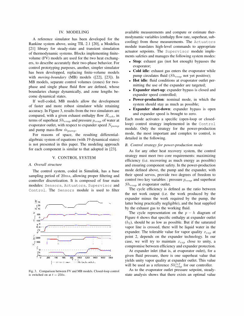
To asses the performance of the control system weuse exhaust mass flow rate and temperature profilescorresponding to on-highway vehicle use, which is ar-guably the most favorable case for waste heat recovery.These profiles come from experimental data recordedon a “Engine-in-the-Loop” test-bench used to evaluatehybrid architectures in the framework of the HyHiLproject [25]. Data correspond to a conventional pow-ertrain architecture (Renault Megane SCENIC II witha 2.0-liter turbocharged SI engine) tested on a (warm)Artemis Motorway Cycle (Figure 8).
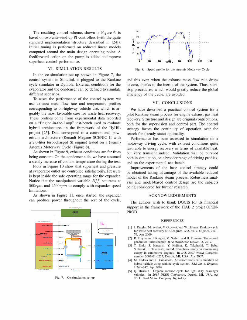
As shown in Figure 9, exhaust conditions are far frombeing constant. On the condenser side, we have assumeda steady increase of coolant temperature during the test.
Plots in Figure 10 show that superheat and pressureat evaporator outlet are controlled satisfactorily. Pressureis kept inside the safe operating range for the expander.Notice that the manipulated variable NSP
exp saturates at500rpm and 2500rpm to comply with expander speedlimitations.
As shown in Figure 11, once started, the expandercan produce power throughout the rest of the cycle,
Fig. 7. Co-simulation set-up
Fig. 8. Speed profile for the Artemis Motorway Cycle
and this even when the exhaust mass flow rate dropsto zero, thanks to the inertia of the system. Thus, start-stop procedures, which would greatly reduce the globalefficiency of the cycle, are avoided.
VII. CONCLUSIONS
We have described a practical control system for apilot Rankine steam process for engine exhaust gas heatrecovery. Structure and design are original contributions,both for the supervision and control part. The controlstrategy favors the continuity of operation over thesearch for (steady-state) optimality.
Performance has been assessed in simulation on amotorway driving cycle, with exhaust conditions quitefavorable to energy recovery in terms of available heat,but very transient indeed. Validation will be pursuedboth in simulation, on a broader range of driving profiles,and on the experimental test bench.
Improvements of the base control strategy couldbe obtained taking advantage of the available reducedmodel of the Rankine steam process. Robustness anal-ysis and model-based control design are the subjectsbeing considered for further research.
ACKNOWLEDGEMENTS
The authors wish to thank DGCIS for its financialsupport in the framework of the ITAE 2 projet OPEN-PROD.
REFERENCES
[1] J. Ringler, M. Seifert, V. Guyotot, and W. Hübner. Rankine cyclefor waste heat recovery of IC engines. SAE Int. J. Engines, 2:67–76, Apr 2009.
[2] R. Freymann, J. Ringler, M. Seifert, and H. Tilmann. The secondgeneration turbosteamer. MTZ Worldwide Edition, 2, 2012.
[3] T. Endo, S. Kawajiri, Y. Kojima, K. Takahashi, T. Baba,S. Ibaraki, T. Takahashi, and M. Shinohara. Study on maximizingexergy in automotive engines. In SAE 2007 World Congress,number 2007-01-0257, Detroit, MI, USA, Apr 2007.
[4] M. Kadota and K. Yamamoto. Advanced transient simulation onhybrid vehicle using rankine cycle system. SAE Int. J. Engines,1:240–247, Apr 2008.
[5] Q. Hussain. Organic rankine cycle for light duty passengervehicles. In 2011 DEER Conference, Detroit, MI, USA, oct2011. Ford Motor Company, light-duty.
Fig. 9. Exhaust gas mass-flow and temperature profiles (data areextrapolated after t = 1068s)
Fig. 10. Tracking performance
Fig. 11. Enthalpy flow rate in the exhaust gas vs. power producedby the expander
[6] C. Nelson. Exhaust energy recovery. In 2009 DEER Conference,Dearborn, MI, USA, Aug 2009. Cummins.
[7] R. Kruiswyk. An engine system approach to exhaust waste heatrecovery. In 2010 DEER Conference, Detroit, MI, USA, Sep2010. Caterpillar.
[8] S. Singh. Exhaust heat driven rankine cycle for a heavy dutydiesel engine. In 2011 DEER Conference, Detroit, MI, USA, oct2011. Detroit Diesel, Daimler Trucks.
[9] T. Howell. Development of an orc system to improve hd truckfuel efficiency. In 2011 DEER Conference, Detroit, MI, USA,oct 2011. Ricardo, Volvo.
[10] R. El Chammas and D. Clodic. Combined cycle for hybridvehicles. In SAE 2005 World Congress, number 2005-01-1171,Detroit, MI, USA, Apr 2005.
[11] A. Boretti. Recovery of exhaust and coolant heat with r245faorganic rankine cycles in a hybrid passenger car with a naturallyaspirated gasoline engine. Journal of Applied Thermal Engineer-ing, 36(0):73 – 77, 2012.
[12] H. Teng, T. Park, G.L. Hunter, and B. van der Velde. A rankinecycle system for recovering waste heat from HD diesel engines-WHR system development. In SAE 2011 World Congress,number 2011-01-0311, Detroit, MI, USA, Apr 2011.
[13] R.K. Stobart, S.M. Hounsham, and R. Weerasinghe. The control-lability of vapour based thermal recovery systems in vehicles. InSAE 2007 World Congress, number 2007-01-0270, Detroit, MI,USA, Apr 2007.
[14] T. Park, H. Teng, G. Hunter, and B. et al. van der Velde. Arankine cycle system for recovering waste heat from HD dieselengines-experimental results. In SAE 2011 World Congress,number 2011-01-1337, Detroit, MI, USA, Apr 2011.
[15] S. Quoilin, R. Aumann, A. Grill, A. Schuster, V. Lemort, andH. Spliethoff. Dynamic modeling and optimal control strategy ofwaste heat recovery organic rankine cycles. Journal of AppliedEnergy, 2011.
[16] X.D. He, S. Liu, and H.H. Asada. Modeling of vapor compres-sion cycles for multivariable feedback control of hvac systems.ASME Journal of dynamic systems, measurement, and control,119:183, 1997.
[17] B. Rasmussen and A. Alleyne. Control-oriented modeling oftranscritical vapor compression systems. ASME Journal ofdynamic systems, measurement, and control, 126:54, 2004.
[18] B Rasmussen. Dynamic modeling and advanced control of airconditioning and refrigeration systems. PhD thesis, Universityof Illinois at Urbana-Champaign, 2005.
[19] A. Alleyne, B. Rasmussen, M. Keir, and B. Eldredge. Advancesin energy systems modeling and control. In American ControlConference, 2007. ACC’07, pages 4363–4373. IEEE, 2007.
[20] C. Richter. Proposal of new object-oriented equation-basedmodel libraries for thermodynamic systems. PhD thesis, TUBraunschweig, 2008.
[21] P.A. Fritzson. Principles of object-oriented modeling and simu-lation with Modelica 2.1. Wiley-IEEE Press, 2004.
[22] M. Gräber, N.C. Strupp, and W. Tegethoff. Moving boundaryheat exchanger model and validation procedure. In EUROSIMCongress on Modelling and Simulation, Prague, Czech Republic,2010.
[23] D. Wei, X. Lu, Z. Lu, and J. Gu. Dynamic modeling and sim-ulation of an organic rankine cycle (orc) system for waste heatrecovery. Journal of Applied thermal engineering, 28(10):1216–1224, 2008.
[24] Karl Johan Åström and Tore Hägglund. PID Controllers: Theory,Design, and Tuning. Instrument Society of America, ResearchTriangle Park, North Carolina, 1995.
[25] A. Del Mastro, A. Chasse, P. Pognant-Gros, P.F. Corde, F. Gallo,and G. Hennequet. Advanced hybrid vehicle simulation: from“Virtual” to “HyHiL” test bench. In SAE 9th InternationalConference on Engines and Vehicles, number 2009-24-0068,Naples, Italy, Sep 2009.