SUPERVISED WIRELESS SECURITY CONTROL PANEL · SUPERVISED WIRELESS SECURITY CONTROL PANEL DUAL 824...
48
SUPERVISED WIRELESS SECURITY CONTROL PANEL DUAL 824 USA & Canada (800) 421-1587 & (800) 392-0123 (760) 438-7000 - Toll Free FAX (800) 468-1340 www.linearcorp.com Installation & Programming Instructions
-
Upload
hoangkhanh -
Category
Documents
-
view
219 -
download
3
Transcript of SUPERVISED WIRELESS SECURITY CONTROL PANEL · SUPERVISED WIRELESS SECURITY CONTROL PANEL DUAL 824...

SUPERVISED WIRELESSSECURITY CONTROL PANEL
DUAL 824
USA & Canada (800) 421-1587 & (800) 392-0123(760) 438-7000 - Toll Free FAX (800) 468-1340
www.linearcorp.com
Installation & Programming Instructions
PRINTER’S INSTRUCTIONS:INSTR,INSTL,DUAL 824 - LINEAR P/N: 217703 D - INK: BLACK - MATERIAL: 20 LB. MEAD BOND WITH 80 LB. WHITE COATED COVER - SIZE: 8.500” X 11.000” - SCALE: 1-1 - FOLDING: ALBUM FOLD - BINDING: SADDLE-STITCH

CONGRATULATIONS for selecting Linear's DUAL 824 Security System. The Model DUAL 824P Control Panel and the Model DUAL 824KP Keypad incorporate many advanced and sophisticated features. The system can be expanded and customized to fi t the installation's specifi c needs.The DUAL 824P Control Panel and its accessories are designed and manufactured by the oldest wireless security company in North America. You can look ahead to many years of reliable service with this Control Panel and its accessories.Many insurance companies offer discounts on homeowners and renters policies when a security system is installed. Discount credits vary with different companies and generally increase in savings with an increase in the level of protection. Inform the user to ask their insurance agent about savings available.The DUAL 824P Control Panel is UL Listed. For a UL smoke alarm system, there must be at least one smoke detector programmed into the Control Panel to meet National Fire Protection Association (NFPA) Rule 72 Chapter 2 and UL 217 requirements. Many insurance companies require these conditions to be met to qualify for a discount. Only use the Model DXS-73 smoke detector with this Control Panel for a UL smoke alarm system.NOTE: Some cities and municipalities may require an alarm system permit. Check with the local authorities before installing this system.In this manual, the bullets preceding the text help to defi ne the information. For example:
✦ This symbol indicates a feature.✴ This symbol is for lit indications or system
sounds.✎ This symbol is for important notes.
CONTROL PANELMODEL DUAL 824P
KEYPADMODEL DUAL 824KP
DUAL 824 SYSTEM
UL Listed as a Single Station Smoke Detector Accessory, also suitable as a Household Burglar-Alarm System Control Unit. UL Category CCN UTGT & NBSX
RING
TIP
R1
T1
DUAL 824 WIRING DIAGRAM
WARNING:
IncomingPhone Line
LocalTelephones
RED
GREEN
GRAY
BROWN
AUXILIARY FUSETYPE 2AG, 1 AMP
ANT
SHIELD
To internal antennawires or to Model LA-Pexternal antenna kit
RED (+)
BLACK (-)
CONNECT TO12 VDC/4AHGEL CELLBATTERY
LOOP1
COM LOOP2
LOOP3
COM LOOP4
LOOP5
COM LOOP6
LOOP7
COM LOOP8
H/A-
H/A+
RLYCOM
RLYN/C
RLYN/O
+12VDC
KPD+
KPD-
KPDCLK
KPDDAT
KPDSPK+
KPDSPK -
AC AC
HARDWIRED LOOP INPUTS OUTPUTS KEYPAD XFRMR
BATTERY FUSETYPE 2AG, 3 AMP
Battery wiresCharging voltage: 13.8 VDC
ANTENNA
BACKUP BATTERY
Normal batterylife should
exceed 3 years
TELEPHONE
Fire protection must follow NFPA Standard No. 72 (National Fire Protection Association, Batterymarch Park, Quincy, MA 02269). Printed information describing proper installation, operation, testing, maintenance, evacuation planning, and repair service is to be provided with this equipment.
TRANSFORMER16VAC, 1.25AConnect to24hr. 120VAC,60 Hz Outlet
LOOP RESPONSE TIME: 400 mS MAXIMUM RECOMMENDED LOOP LENGTH: 500 FEET
AUTOMATIONOUTPUT
Current limitedswitched
+12 VDC, 40 mAvoltage source
See instructionsfor output options
ALARM RELAYRated 12 volts,
1 amp maximum
EXTERNAL SIREN12 VDC at 1 Amp
maximum
To any COM terminal
RE
D
BLA
CK
OR
AN
GE
WH
ITE
KEYPAD WIRING4-conductor 22 AWG wire
Up to 100 feet for all keypads used allowed
DUAL 824KPHARDWIRED KEYPAD
ONE OR TWOUNITS ALLOWED
AUXILIARYPOWEROUTPUT
12 VDC at 1 Ampmaximum
FOR INSTALLATION INSTRUCTIONS, REFER TO THE MANUAL SUPPLIED WITH THIS PRODUCT
N.C.
2.2kE.O.L.
RESISTOR
LOOP 1
N.C.
2.2kE.O.L.
RESISTOR
LOOP 2
N.O. N.O.
N.C.
2.2kE.O.L.
RESISTOR
LOOP 3
N.C.
2.2kE.O.L.
RESISTOR
LOOP 4
N.O. N.O.
N.C.
2.2kE.O.L.
RESISTOR
LOOP 5
N.C.
2.2kE.O.L.
RESISTOR
LOOP 6
N.O. N.O.
N.C.
2.2kE.O.L.
RESISTOR
LOOP 7
N.C.
2.2kE.O.L.
RESISTOR
LOOP 8
N.O. N.O.
CAUTION: IMPORTANT:
(760) 438-7000 • FAX (760) 438-7043USA & Canada (800) 421-1587 & (800) 392-0123
Toll Free FAX (800) 468-1340www.linearcorp.com
1) MISCONNECTIONS MAY CAUSE DAMAGE TOCONTROL PANEL ELECTRONICS2) DO NOT REVERSE BATTERY LEADS3) TO PREVENT RISK OF ELECTRICAL SHOCK,DISCONNECT TELCO JACK BEFORE SERVICINGTHIS CONTROL PANEL4) FOR CONTINUED PROTECTION AGAINST FIRE,REPLACE ONLY WITH SAME TYPE AND RATING OFFUSES
1) NO USER SERVICABLE PARTS INSIDE2) RISK OF FIRE AND ELECTRICAL SHOCK, ROUTEWIRES AWAY FROM INTERNAL COMPONENTS3) REMOVE AC POWER BEFORE CONNECTINGTRANSFORMER, BATTERY, OR REPLACING FUSES
1) USE UL LISTED CABLE FOR ALL CONNECTIONS2) WEEKLY TESTING IS REQUIRED TO ENSURE PROPEROPERATION OF THIS SYSTEM3) DO NOT CONNECT AC POWER TO A RECEPTACLECONTROLLED BY A SWITCH4) CONNECTION OF THE FIRE ALARM SIGNAL TO AFIRE ALARM HEADQUARTERS OR A CENTRAL STATIONSHALL BE PERMITTED ONLY WITH THE APPROVAL OFTHE LOCAL AUTHORITY HAVING JURISDICTION. THEBURGLAR ALARM SIGNAL SHALL NOT BE CONNECTEDTO A POLICE EMERGENCY NUMBER.
LINEAR LLCRESIDENTIAL SECURITY RECEIVERMODEL: DUAL 824PART # SSC00056FREQUENCY: 315 MHzPOWER SUPPLY: 16 VAC, 1.25AThis device complies with FCC Part 15 and IC Canada Rules and Regulations. Operation is subject to the following two conditions: (1) This device may not cause harmful interference and (2) this device must accept any interference received, including interference that may cause undesired operation.Complies with Part 68, FCC Rules.FCC Registration Number: EF4HKG-31823-AL-ERinger Equivalence Number: 1.7B
Warranty Expiration Date:
MODEL RSM-2VOICE RESPONSE
SPEAKER8 Ohm - 2 Watts
USOC JACKS:RJ31X, RJ38X
MADE IN CHINA 454
CANADIAN REGULATORY INFORMATION
IC ID 1078-102-556AComplies with IC RSS 210En conformité avec IC CNR 210.
INTRODUCTION

1
1. THE DUAL 824 SECURITY SYSTEM. . . . . . . . . . . . . . . . . . . . . . . . . . . . . . . . . . . . . . . 2 CONTROL PANEL . . . . . . . . . . . . . . . . . . . . . . . . . . . . . . . . . . . . . . . . . . . . . . . . . 2 DOOR/WINDOW SENSORS . . . . . . . . . . . . . . . . . . . . . . . . . . . . . . . . . . . . . . . . . 3 WIRELESS KEYPAD . . . . . . . . . . . . . . . . . . . . . . . . . . . . . . . . . . . . . . . . . . . . . . . 3 SMOKE DETECTOR . . . . . . . . . . . . . . . . . . . . . . . . . . . . . . . . . . . . . . . . . . . . . . . 3 REMOTE CONTROLS . . . . . . . . . . . . . . . . . . . . . . . . . . . . . . . . . . . . . . . . . . . . . . 3 GLASS BREAK DETECTOR . . . . . . . . . . . . . . . . . . . . . . . . . . . . . . . . . . . . . . . . . 3 PANIC BUTTONS . . . . . . . . . . . . . . . . . . . . . . . . . . . . . . . . . . . . . . . . . . . . . . . . . 3 BILL TRAP . . . . . . . . . . . . . . . . . . . . . . . . . . . . . . . . . . . . . . . . . . . . . . . . . . . . . . . 3 PASSIVE INFRARED MOTION DETECTOR. . . . . . . . . . . . . . . . . . . . . . . . . . . . . 32. SECURITY SYSTEM FLOOR PLAN . . . . . . . . . . . . . . . . . . . . . . . . . . . . . . . . . . . . . . . 4 EXAMPLE SYSTEM . . . . . . . . . . . . . . . . . . . . . . . . . . . . . . . . . . . . . . . . . . . . . . . 4 DESIGN THE INSTALLATION . . . . . . . . . . . . . . . . . . . . . . . . . . . . . . . . . . . . . . . . 43. OVERVIEW OF KEYPADS . . . . . . . . . . . . . . . . . . . . . . . . . . . . . . . . . . . . . . . . . . . . . . . 5 HARDWIRED KEYPAD . . . . . . . . . . . . . . . . . . . . . . . . . . . . . . . . . . . . . . . . . . . . . 5 WIRELESS KEYPAD . . . . . . . . . . . . . . . . . . . . . . . . . . . . . . . . . . . . . . . . . . . . . . . 5 ABOUT SENSOR STATUS SUPERVISION . . . . . . . . . . . . . . . . . . . . . . . . . . . . . 54. HARDWIRED KEYPAD FEATURES . . . . . . . . . . . . . . . . . . . . . . . . . . . . . . . . . . . . . . . . 65. CONTROL PANEL FEATURES . . . . . . . . . . . . . . . . . . . . . . . . . . . . . . . . . . . . . . . . . . . 76. CONTROL PANEL INSTALLATION . . . . . . . . . . . . . . . . . . . . . . . . . . . . . . . . . . . . . . . . 8 SYSTEM LOCATION . . . . . . . . . . . . . . . . . . . . . . . . . . . . . . . . . . . . . . . . . . . . . . . 8 WALL MOUNTING . . . . . . . . . . . . . . . . . . . . . . . . . . . . . . . . . . . . . . . . . . . . . . . . . 8 EXTERNAL ANTENNA . . . . . . . . . . . . . . . . . . . . . . . . . . . . . . . . . . . . . . . . . . . . . 8 HARDWIRED KEYPAD INSTALLATION . . . . . . . . . . . . . . . . . . . . . . . . . . . . . . . . 9 HARDWIRED LOOP WIRING . . . . . . . . . . . . . . . . . . . . . . . . . . . . . . . . . . . . . . . 10 ARM/DISARM KEY STATION WIRING . . . . . . . . . . . . . . . . . . . . . . . . . . . . . . . . 10 EXTERNAL ALARM SIREN CONNECTION . . . . . . . . . . . . . . . . . . . . . . . . . . . . 11 TELEPHONE LINE CONNECTION . . . . . . . . . . . . . . . . . . . . . . . . . . . . . . . . . . 11 AUTOMATION OUTPUT CONNECTION . . . . . . . . . . . . . . . . . . . . . . . . . . . . . . 12 VOICE RESPONSE MODULE . . . . . . . . . . . . . . . . . . . . . . . . . . . . . . . . . . . . . . 12 CONTROL PANEL POWER CONNECTION . . . . . . . . . . . . . . . . . . . . . . . . . . . . 13 BACKUP BATTERY INSTALLATION . . . . . . . . . . . . . . . . . . . . . . . . . . . . . . . . . 137. BASIC CONTROL PANEL PROGRAMMING . . . . . . . . . . . . . . . . . . . . . . . . . . . . . . . . 14 CREATE THE MASTER USER CODE . . . . . . . . . . . . . . . . . . . . . . . . . . . . . . . . 14 PROGRAM THE HARDWIRED LOOPS . . . . . . . . . . . . . . . . . . . . . . . . . . . . . . . 15 PROGRAM THE WIRELESS SENSORS . . . . . . . . . . . . . . . . . . . . . . . . . . . . . . 15 PROGRAMMING DIFFERENT SENSOR TYPES . . . . . . . . . . . . . . . . . . . . . . . . 168. BASIC SENSOR INSTALLATION. . . . . . . . . . . . . . . . . . . . . . . . . . . . . . . . . . . . . . . . . 18 DXS-10 WIRELESS KEYPAD . . . . . . . . . . . . . . . . . . . . . . . . . . . . . . . . . . . . . . . 18 DXS-31 & DXS-32 DOOR/WINDOW SENSORS . . . . . . . . . . . . . . . . . . . . . . . . 19 TEST SENSORS . . . . . . . . . . . . . . . . . . . . . . . . . . . . . . . . . . . . . . . . . . . . . . . . . 199. CUSTOMIZING THE KEYPAD . . . . . . . . . . . . . . . . . . . . . . . . . . . . . . . . . . . . . . . . . . . 20 LABELING THE SENSOR LOCATIONS . . . . . . . . . . . . . . . . . . . . . . . . . . . . . . . 2010. SYSTEM OPERATING MODES . . . . . . . . . . . . . . . . . . . . . . . . . . . . . . . . . . . . . . . . . . 21 OFF MODE . . . . . . . . . . . . . . . . . . . . . . . . . . . . . . . . . . . . . . . . . . . . . . . . . . . . . 21 CHIME MODE . . . . . . . . . . . . . . . . . . . . . . . . . . . . . . . . . . . . . . . . . . . . . . . . . . . 21 HOME MODE . . . . . . . . . . . . . . . . . . . . . . . . . . . . . . . . . . . . . . . . . . . . . . . . . . . 22 SECURE EXIT . . . . . . . . . . . . . . . . . . . . . . . . . . . . . . . . . . . . . . . . . . . . . . . . . . . 22 HOME INSTANT MODE . . . . . . . . . . . . . . . . . . . . . . . . . . . . . . . . . . . . . . . . . . . 22 MANUAL BYPASSING OF SENSORS . . . . . . . . . . . . . . . . . . . . . . . . . . . . . . . . 22 AWAY MODE . . . . . . . . . . . . . . . . . . . . . . . . . . . . . . . . . . . . . . . . . . . . . . . . . . . . 23 MANUAL BYPASSING OF SENSORS . . . . . . . . . . . . . . . . . . . . . . . . . . . . . . . . 23 TEST MODE . . . . . . . . . . . . . . . . . . . . . . . . . . . . . . . . . . . . . . . . . . . . . . . . . . . . 2411. SYSTEM TROUBLE INDICATIONS . . . . . . . . . . . . . . . . . . . . . . . . . . . . . . . . . . . . . . . 25 CONTROL PANEL POWER . . . . . . . . . . . . . . . . . . . . . . . . . . . . . . . . . . . . . . . . 25 WIRELESS SENSOR LOW BATTERIES . . . . . . . . . . . . . . . . . . . . . . . . . . . . . . 25 SENSOR RADIO TROUBLE . . . . . . . . . . . . . . . . . . . . . . . . . . . . . . . . . . . . . . . . 2512. CUSTOMIZING THE SYSTEM . . . . . . . . . . . . . . . . . . . . . . . . . . . . . . . . . . . . . . . . . . . 26 ADDING SENSORS TO THE SYSTEM . . . . . . . . . . . . . . . . . . . . . . . . . . . . . . . . 26 REMOVING SENSORS FROM THE SYSTEM . . . . . . . . . . . . . . . . . . . . . . . . . . 26 MAKING A SENSOR A 24-HOUR DOOR CHIME . . . . . . . . . . . . . . . . . . . . . . . 27 MAKING A SENSOR INTERIOR . . . . . . . . . . . . . . . . . . . . . . . . . . . . . . . . . . . . . 27 MAKING A SENSOR PERFORM A DIFFERENT FUNCTION . . . . . . . . . . . . . . 28
13. ADVANCED PROGRAMMING . . . . . . . . . . . . . . . . . . . . . . . . . . . . . . . . . . . . . . . . . . . 29 SETUP MODE . . . . . . . . . . . . . . . . . . . . . . . . . . . . . . . . . . . . . . . . . . . . . . . . . . . 29 CHANGING A SENSORS SUPERVISION . . . . . . . . . . . . . . . . . . . . . . . . . . . . . 30 CHANGING A SENSORS RESTORE REQUIREMENTS . . . . . . . . . . . . . . . . . . 30 ENTRY DELAY TIME . . . . . . . . . . . . . . . . . . . . . . . . . . . . . . . . . . . . . . . . . . . . . . 30 EXIT DELAY TIME . . . . . . . . . . . . . . . . . . . . . . . . . . . . . . . . . . . . . . . . . . . . . . . . 30 BURGLARY SIREN TIME . . . . . . . . . . . . . . . . . . . . . . . . . . . . . . . . . . . . . . . . . . 30 EMERGENCY SIREN TIME . . . . . . . . . . . . . . . . . . . . . . . . . . . . . . . . . . . . . . . . 30 FIRE SIREN TIME . . . . . . . . . . . . . . . . . . . . . . . . . . . . . . . . . . . . . . . . . . . . . . . . 31 AUTOMATION OUTPUT TIME . . . . . . . . . . . . . . . . . . . . . . . . . . . . . . . . . . . . . . 31 REMOTE CONTROL & HARDWIRE ARMING LEVEL . . . . . . . . . . . . . . . . . . . . 31 REMOTE CONTROL & HARDWIRE DISARMING LEVEL . . . . . . . . . . . . . . . . . 31 ENTRY DELAY BEEPS . . . . . . . . . . . . . . . . . . . . . . . . . . . . . . . . . . . . . . . . . . . . 31 EXIT DELAY BEEPS . . . . . . . . . . . . . . . . . . . . . . . . . . . . . . . . . . . . . . . . . . . . . . 31 SILENT BURGLARY ALARMS . . . . . . . . . . . . . . . . . . . . . . . . . . . . . . . . . . . . . . 32 SILENT EMERGENCY ALARMS . . . . . . . . . . . . . . . . . . . . . . . . . . . . . . . . . . . . 32 DISABLING QUICK ARMING . . . . . . . . . . . . . . . . . . . . . . . . . . . . . . . . . . . . . . . 32 AUTOMATIC RESTORAL OF BYPASSED SENSORS . . . . . . . . . . . . . . . . . . . . 32 AUTOMATIC BYPASSING OF OPEN SENSORS . . . . . . . . . . . . . . . . . . . . . . . . 32 AUTOMATION OUTPUT MODE DURING ALARM . . . . . . . . . . . . . . . . . . . . . . . 33 AUTOMATION ACTIVATION TONE . . . . . . . . . . . . . . . . . . . . . . . . . . . . . . . . . . . 33 REMOTE CONTROL & HARDWIRE ARM/DISARM CHIRP . . . . . . . . . . . . . . . . 33 AUTOMATION OUTPUT ON DURING AND AFTER ALARM . . . . . . . . . . . . . . . 33 AUTOMATION OUTPUT ON DURING ALARM . . . . . . . . . . . . . . . . . . . . . . . . . . 33 AUTOMATION OUTPUT WHILE ARMED . . . . . . . . . . . . . . . . . . . . . . . . . . . . . . 34 AUTOMATION OUTPUT DURING EXIT/ENTRY DELAYS . . . . . . . . . . . . . . . . . 34 AUTOMATION OUTPUT POLARITY . . . . . . . . . . . . . . . . . . . . . . . . . . . . . . . . . . 34 REMOTE ACCESS PASSWORD . . . . . . . . . . . . . . . . . . . . . . . . . . . . . . . . . . . . 34 DURESS CODE . . . . . . . . . . . . . . . . . . . . . . . . . . . . . . . . . . . . . . . . . . . . . . . . . 34 MASTER USER CODE . . . . . . . . . . . . . . . . . . . . . . . . . . . . . . . . . . . . . . . . . . . . 34 ADDING ADDITIONAL USER CODES . . . . . . . . . . . . . . . . . . . . . . . . . . . . . . . . 35 REMOVING ADDITITIONAL USER CODES . . . . . . . . . . . . . . . . . . . . . . . . . . . . 35 CONTROL PANEL MASTER RESET . . . . . . . . . . . . . . . . . . . . . . . . . . . . . . . . . 3514. COMMUNICATOR PROGRAMMING . . . . . . . . . . . . . . . . . . . . . . . . . . . . . . . . . . . . . . 36 SETUP MODE . . . . . . . . . . . . . . . . . . . . . . . . . . . . . . . . . . . . . . . . . . . . . . . . . . . 36 GENERAL COMMUNICATOR OPTIONS . . . . . . . . . . . . . . . . . . . . . . . . . . . . . . 37 COMMUNICATOR ENABLE . . . . . . . . . . . . . . . . . . . . . . . . . . . . . . . . . . . . . . . . 37 2-WAY AUDIO . . . . . . . . . . . . . . . . . . . . . . . . . . . . . . . . . . . . . . . . . . . . . . . . . . . 37 VOICE RESPONSE . . . . . . . . . . . . . . . . . . . . . . . . . . . . . . . . . . . . . . . . . . . . . . . 37 REMOTE LOCKOUT . . . . . . . . . . . . . . . . . . . . . . . . . . . . . . . . . . . . . . . . . . . . . . 37 CALL LIMITER . . . . . . . . . . . . . . . . . . . . . . . . . . . . . . . . . . . . . . . . . . . . . . . . . . . 38 DIALING DELAY . . . . . . . . . . . . . . . . . . . . . . . . . . . . . . . . . . . . . . . . . . . . . . . . . 38 DIALING METHOD . . . . . . . . . . . . . . . . . . . . . . . . . . . . . . . . . . . . . . . . . . . . . . . 38 COMMUNICATOR REPORTING OPTIONS . . . . . . . . . . . . . . . . . . . . . . . . . . . . 39 REPORTING FORMAT . . . . . . . . . . . . . . . . . . . . . . . . . . . . . . . . . . . . . . . . . . . . 39 CALL ROUTING . . . . . . . . . . . . . . . . . . . . . . . . . . . . . . . . . . . . . . . . . . . . . . . . . 39 ACCOUNT NUMBER . . . . . . . . . . . . . . . . . . . . . . . . . . . . . . . . . . . . . . . . . . . . . 40 PRIMARY TELEPHONE NUMBER . . . . . . . . . . . . . . . . . . . . . . . . . . . . . . . . . . . 40 SECONDARY TELEPHONE NUMBER . . . . . . . . . . . . . . . . . . . . . . . . . . . . . . . . 40 SUPERVISORY OR PAGER TELEPHONE NUMBER . . . . . . . . . . . . . . . . . . . . 40 TELEPHONE NUMBER DELAYS AND SPECIAL CHARACTERS . . . . . . . . . . . 40 REPORT CONTROL PANEL TROUBLE . . . . . . . . . . . . . . . . . . . . . . . . . . . . . . . 41 REPORT FORCE ARMING . . . . . . . . . . . . . . . . . . . . . . . . . . . . . . . . . . . . . . . . . 41 OPENING AND CLOSING REPORTS . . . . . . . . . . . . . . . . . . . . . . . . . . . . . . . . 41 POINT ID REPORTING . . . . . . . . . . . . . . . . . . . . . . . . . . . . . . . . . . . . . . . . . . . . 41 COMMUNICATOR REPORTING CODES . . . . . . . . . . . . . . . . . . . . . . . . . . . . . . 42 GENERAL REPORTING CODES . . . . . . . . . . . . . . . . . . . . . . . . . . . . . . . . . . . . 42 SYSTEM REPORTING CODES . . . . . . . . . . . . . . . . . . . . . . . . . . . . . . . . . . . . . 43 FORCE ARMING REPORTING CODE . . . . . . . . . . . . . . . . . . . . . . . . . . . . . . . . 43 DURESS REPORTING CODE . . . . . . . . . . . . . . . . . . . . . . . . . . . . . . . . . . . . . . 43 4 BY 2 FORMAT POINT ID REPORTING CODES . . . . . . . . . . . . . . . . . . . . . . . 44 4 BY 2 FORMAT POINT ID ALARM REPORT CODES. . . . . . . . . . . . . . . . . . . . 44 4 BY 2 FORMAT POINT ID TROUBLE REPORT CODES . . . . . . . . . . . . . . . . . 44IMPORTANT INFORMATION . . . . . . . . . . . . . . . . . . . . . . . . . . . . . . . . . . . . . . . . . . . . . . . 46 LINEAR LIMITED WARRANTY . . . . . . . . . . . . . . . . . . . . . . . . . . . . . . . . . . . . . . 46 WIRELESS PRODUCT NOTICE . . . . . . . . . . . . . . . . . . . . . . . . . . . . . . . . . . . . . 46 FCC NOTICE . . . . . . . . . . . . . . . . . . . . . . . . . . . . . . . . . . . . . . . . . . . . . . . . . . . . 46 FCC TELEPHONE RULES AND REGULATIONS . . . . . . . . . . . . . . . . . . . . . . . . 46 FIRE EVACUATION PLANNING . . . . . . . . . . . . . . . . . . . . . . . . . . . . . . . . . . . . . 46 INDUSTRY CANADA NOTICES . . . . . . . . . . . . . . . . . . . . . . . . . . . . . . . . . . . . . 46
TABLE OF CONTENTS
2
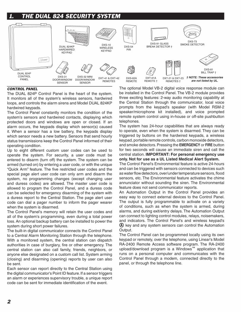
CONTROL PANELThe DUAL 824P Control Panel is the heart of the system. It monitors all of the system's wireless sensors, hardwired loops, and controls the alarm sirens and Model DUAL 824KP hardwired keypads.The Control Panel constantly monitors the condition of the system's sensors and hardwired contacts, displaying which protected doors and windows are open or closed. If an alarm occurs, the keypads display which sensor(s) caused it. When a sensor has a low battery, the keypads display which sensor needs a new battery. Sensors that send hourly status transmissions keep the Control Panel informed of their operating condition.Up to eight different custom user codes can be used to operate the system. For security, a user code must be entered to disarm (turn off) the system. The system can be armed (turned on) by entering a user code, or with the unique “Quick Arm” feature. The fi ve restricted user codes and the special page alert user code can only arm and disarm the system, no programming changes (except changing user and duress codes) are allowed. The master user code is allowed to program the Control Panel, and a duress code can be selected for emergency disarming of the system with a duress report to the Central Station. The page alert user code can dial a pager number to inform the pager wearer when the system is disarmed.The Control Panel's memory will retain the user codes and all of the system's programming, even during a total power loss. An optional backup battery can be installed to power the system during short power failures.The built-in digital communicator connects the Control Panel to a Central Alarm Monitoring Station through the telephone. With a monitored system, the central station can dispatch authorities in case of burglary, fi re or other emergency. The central station can also call family, friends, neighbors, or anyone else designated on a custom call list. System arming (closing) and disarming (opening) reports by user can also be sent.Each sensor can report directly to the Central Station using the digital communicator's Point ID feature. If a sensor triggers an alarm or experiences supervisory trouble, a unique report code can be sent for immediate identifi cation of the event.
The optional Model VB-2 digital voice response module can be installed in the Control Panel. The VB-2 module provides three exciting features: 2-way audio monitoring capability at the Central Station through the communicator, local voice prompts from the keypad's speaker (with Model RSM-2 speaker/microphone kit installed), and voice prompted remote system control using in-house or off-site pushbutton telephones.The system has 24-hour capabilities that are always ready to operate, even when the system is disarmed. They can be triggered by buttons on the hardwired keypads, a wireless keypad, portable remote controls, carbon monoxide detectors, and smoke detectors. Pressing the EMERGENCY or FIRE button for two seconds will cause an immediate siren and call the central station. IMPORTANT: For personal emergency use only. Not for use as a UL Listed Medical Alert System.The Control Panel's Environmental feature is active 24-hours and can be triggered with sensors connected to devices such as water fl ow detectors, over/under temperature sensors, fl ood sensors, etc. The Environmental feature activates the chime annunciator without sounding the siren. The Environmental feature does not send communicator reports.An Automation Output in the Control Panel provides an easy way to connect external devices to the Control Panel. The output is fully programmable to activate on a variety of conditions, such as when the system is armed, during alarms, and during exit/entry delays. The Automation Output can connect to lighting control modules, relays, noisemakers, and indicators. The Control Panel's and wireless keypad's
key and any system sensors can control the Automation Output.The Control Panel can be programmed locally using its own keypad or remotely, over the telephone, using Linear's Model RA-2400 Remote Access software program. The RA-2400 upload/download program is a Windows™ application that runs on a personal computer and communicates with the Control Panel through a modem, connected directly to the panel, or through the telephone line.
1. THE DUAL 824 SECURITY SYSTEM
DXS-91 GLASSBREAK DETECTOR †
DXS-73SMOKE DETECTOR
DUAL 824PCONTROL
PANEL
DXS-10WIRELESSKEYPAD
DXS-31DOOR/WINDOW
SENSOR
DXS-54PIR
DXT-41 & DXT-42REMOTES
DXT-61AREMOTE †
DXS-81BILL TRAP †
DXT-21 & DXT-23REMOTES †
DUAL 824KPHARDWIRED
KEYPAD
DXS-32 MINIDOOR/WINDOW
SENSOR
DXS-62AREMOTE
† NOTE: These accessories are not listed by UL.

3
DOOR/WINDOW SENSORSThe DXS-31 and DXS-32 sensors monitor doors and windows. They send radio signals to the Control Panel. One type of signal is sent when the door or window is opened, and a different type of signal is sent when the door or window is closed. If the system is armed, a sensor can trigger the Control Panel's burglary siren when its door or window is opened. Both sensors are supervised, send hourly status reports, and monitor their battery condition.
WIRELESS KEYPADThe DXS-10 wireless keypad is used to operate the system remotely. It can be placed in a convenient spot so the user doesn't have to go to the hardwired keypad to operate the system. The wireless keypad can also trigger the emergency or fi re siren and actuate the Automation Output. Pressing will cause the hardwired keypad(s) to sound Beeps corresponding to the current operating mode. The DXS-10 is supervised, it sends hourly status reports and monitors its battery condition. IMPORTANT: For personal emergency use only. Not for use as a UL Listed Medical Alert System.
SMOKE DETECTORThe DXS-73 is a high quality smoke detector with a built-in radio transmitter. As soon as smoke is detected, the unit will sound its local noisemaker. Then, 20 seconds after the local noisemaker sounds, the transmitter sends an alarm signal to the Control Panel. The alarm signal will be repeated every 20 seconds as long as smoke is still present. A restoral signal will be sent when the smoke detection chamber clears. The DXS-73 is supervised, it sends hourly status reports, and monitors its battery condition.
☞ NOTE: A Model DXS-73 Smoke Detector is required to create a UL Listed smoke alarm system. See Page 26 for details on adding a smoke detector sensor to the system.
REMOTE CONTROLSThe DXT-41, DXT-61 single-button and DXT-23, DXT-42 multi-button remote controls can be used to remotely arm and disarm the system. The DXT-42’s left button will arm and the right button will disarm the system. Pressing both buttons simultaneously will trigger the emergency siren. Alternately the Control Panel can be programmed to respond to the DXT-42 by arming and disarming with the left button, and activating the automation output with the right button. These transmitters can also be programmed to activate various other Control Panel zones. These transmitters are not supervised.
GLASS BREAK DETECTORThe DXS-91 is a glass break detector with an audio sound discriminator and a built-in radio transmitter. The unit “listens” for the sound of breaking glass. When glass breakage is detected, the unit sends an alarm signal to the Control Panel. The DXS-91 is supervised, it sends hourly status reports and monitors its battery condition.
PANIC BUTTONSThe DXT-21, DXS-21 single-button, and DXT-23, DXS-23 two-button transmitters can be used as portable “panic buttons”. Pressing the front or top button on the DXT-21 or DXS-21 at any time will trigger the emergency siren. Pressing both front buttons simultaneously on the DXT-23 or DXS-23 at any time will trigger the emergency siren. These transmitters can be programmed to activate various other system functions. The DXT-21 and DXT-23 transmitters are not supervised. The DXS-21 and DXS-23 transmitters are supervised.The DXS-62A transmitter is typically used as a portable “panic button”. Pressing the button on a DXS-62A at any time will trigger the emergency siren. This transmitter can send hourly status signals and low battery signals if the battery is low.
BILL TRAPThe DXS-81 bill trap can be used with the Control Panel in non-UL small commercial hold-up installations. The unit is concealed in a cash drawer under a stack of currency, with a single “bait” bill secured in its money clip. During a hold-up, the cashier removes the stack of currency along with the “bait” bill. When a “bait” bill is removed, the transmitter sends a signal to the Control Panel. Four additional signals are sent within the fi rst minute after the “bait” bill is removed. When the “bait” bill is replaced, a restore signal is sent. The DXS-81 is supervised, it can send hourly status reports (optional) and monitors its battery condition.
PASSIVE INFRARED MOTION DETECTORThe DXS-54 is a passive infrared (PIR) motion detector with a built-in radio transmitter. The PIR detects motion in its detection pattern by measuring the infrared emission levels of objects that it “sees”. If the infrared levels change quickly, as when a person moves across the detection pattern, the PIR will recognize the change as an intrusion and send an alarm signal to the Control Panel. An alarm will be triggered if the system is in the Away Mode. The DXS-54 is supervised, it sends hourly status reports and monitors its battery condition.
DXS-31DXS-32
DXS-10
DXS-73
DXT-41
DXT-61‡
DXT-42
DXS-91‡
DXT-21‡ DXS-21‡ DXT-23‡ DXS-23‡ DXS-62A
DXS-81‡
DXS-54
‡ NOTE: These accessories not listed by UL

4
EXAMPLE SYSTEM✦ The example shows a typical DUAL 824 system.✦ Any or all of the accessories shown can be used.✦ A total of 24 sensors can be used with each
Control Panel. Each wireless sensor, hardwired loop, and wireless keypad used occupies a sensor location.
DESIGN THE INSTALLATION1. Draw a fl oor plan for the installation.2. Consider the security needs of the premises.3. Determine which doors and windows are
vulnerable to intrusion.4. Figure which interior areas an intruder might go
to if unlawful entrance is gained.5. Indicate locations for door/window sensors,
interior motion detectors, wireless and hardwired keypads, glass break detectors and external siren speakers.
6. Decide on a centralized location for the security Control Panel.
2. SECURITY SYSTEM FLOOR PLAN
CP
S
GARAGE
MS
S
MD
ES
HK
S
S
MD MSS
S
CP - CONTROL PANELHK - HARDWIRED KEYPADS - DOOR/WINDOW SENSORWK - WIRELESS KEYPADMD - MOTION DETECTORES - EXTERNAL SIRENSD - SMOKE DETECTORCO - CARBON MONOXIDE DETECTORGB - GLASS BREAK SENSORMS - HARDWIRED MAGNETIC SWITCH
LIVING
DINING
KITCHEN
ENTRY
BED
BATHDEN
GB
SD
GB
BED
NOTE: IN NEW CONSTRUCTION, NFPA 72 REQUIRES A SMOKE DETECTOR LOCATED INSIDE EACH BEDROOMAS WELL AS A SMOKE DETECTOR ON EACH LEVEL.
MS
WK
HKS
S
S
CO
Example Residential Security System Floor Plan

5
HARDWIRED KEYPAD✦ One or two hardwired keypads can be used for
controlling the system.✦ Three system status indicators:
READY, ARMED, & TROUBLE✦ Three system supervisory indicators:
POWER, BATTERIES, & RADIO✦ Five system mode indicators:
OFF, CHIME, HOME, AWAY & TEST✦ 24 system sensor indicators.✦ Location inside beauty cover for supplied sensor
identifi cation labels.✦ Press to activate the automation output.✦ Pressing clears the keypad.✦ Pressing for two seconds sounds the mode
Beeps from the hardwired keypad(s).✔ Off Mode: 1 “Gong”.✔ Chime Mode: 1 “Gong” & 1 “Beep”.✔ Home Mode: 1 “Gong” & 2 “Beeps”.✔ Away Mode: 1 “Gong” & 3 “Beeps”.✔ Test Mode: 1 “Gong” & 4 “Beeps”.
✦ Emergency and fi re alarm can be triggered from the keypad at any time.
✎ UL NOTE: For personal emergency use only. Not for use as a UL Listed Medical Alert System.
WIRELESS KEYPAD✦ For controlling the system remotely.✦ Green operation light.✦ Internal 9-volt battery is monitored by the Control
Panel.✦ Keypad's beeper will buzz during transmissions
when the battery is low.✦ Up to 3 years battery life (depends on frequency
of activation). (UL tested for 1 year minimum.)✦ Sends hourly status reports to the Control Panel.✦ Press to activate the automation output.✦ Pressing clears the keypad.✦ Pressing for two seconds sounds the mode
Beeps from the hardwired keypad(s).✔ Off Mode: 1 “Gong”.✔ Chime Mode: 1 “Gong” & 1 “Beep”.✔ Home Mode: 1 “Gong” & 2 “Beeps”.✔ Away Mode: 1 “Gong” & 3 “Beeps”.✔ Test Mode: 1 “Gong” & 4 “Beeps”.
✦ Emergency and fi re alarm can be triggered from the wireless keypad at any time.
✎ UL NOTE: For personal emergency use only. Not for use as a UL Listed Medical Alert System.
ABOUT SENSOR STATUS SUPERVISIONAll DXS Format sensors transmit hourly status reports. All DXT Format sensors do not transmit hourly status reports. Both sensor formats can be used with the system.When a sensor is programmed into the Control Panel, the system will set the sensor as non-supervised or supervised. Sensors set as non-supervised are not expected to send hourly status reports. Sensors set as supervised are expected to send hourly status reports. If a status report is not received in 8 hours from a sensor set as supervised, the RADIO indicator will fl ash.When sensors are programmed into the Control Panel, ALL STATIONARY SENSORS ARE SET AS SUPERVISED, ALL PORTABLE SENSORS ARE SET AS NON-SUPERVISED.If stationary DXT Format sensors have been programmed into the Control Panel, be sure to change their setting to non-supervised to prevent RADIO indications. This will not prevent low battery monitoring.If portable DXS Format sensors have been programmed into the Control Panel, and the installation requires supervision for specifi c portable sensor(s), change the selected portable sensors setting to supervised.After programming the sensors, if changes are required, refer to “Changing a Sensors Supervision” on Page 30 for details on changing the way a sensor’s supervision is set.
3. OVERVIEW OF KEYPADS
HARDWIREDKEYPAD
WIRELESSKEYPAD

6
1 BEAUTY COVER★ The beauty cover snaps open and shut to hide the keypad’s keys, mode and
supervisory indicators, and the sensor location labeling area.
2 KEYPAD★ Backlit keys for easy viewing in low light conditions.★ For entering the user's user code (numerically or alphabetically).★ Used when programming system options.★ Press to activate the Automation Output.★ Press to clear keypad if the wrong key is pressed.★ Press for two seconds to view sensor battery and supervisory status (see
BATTERIES and RADIO indicator description).
3 24-HOUR BUTTONS★ Pressing FIRE for two seconds sounds the fi re siren and sends a “fi re” message
to a central monitoring station through the digital communicator (if the system is monitored).
★ Pressing EMERGENCY for two seconds sounds the emergency siren and sends an “emergency” message to a central monitoring station through the digital communicator (if the system is monitored).
★ Both work even when system is disarmed.★ IMPORTANT: For personal emergency use only. Not for use as a UL Listed
Medical Alert System.
4 SYSTEM SUPERVISORY INDICATORS★ Shows the current status of the system.
POWER LIGHT★ Glows when AC power is on.★ Blinks when AC power is off and backup battery is installed.★ Blinks when the backup battery is low, recharging or missing.★ Off when AC power is off and no backup battery is installed (system disabled).
BATTERIES LIGHT★ Blinks when one or more sensors have a low battery.★ Press for two seconds to view sensor status. Sensor status indicator for any
sensor with a low battery will light along with the BATTERIES indicator.★ Switch to Test Mode after replacing the sensor battery and completely test the
system (see Test Mode). Switching to Test Mode clears the low battery indication.
RADIO LIGHT★ Blinks when one or more sensors have not reported status during the eight hour
status time period. ★ Press for two seconds to view sensor status. Sensor status indicator for any
sensor that has not reported in will light along with the TROUBLE indicator.★ Switch to Test Mode after servicing the sensor and completely test the system
(see Test Mode). Switching to Test Mode clears the trouble indication.
5 MODE INDICATORS★ The indicators next to the mode keys light to show the current system mode.★ HOME indicator will blink during Secure Exit and Home Instant modes.★ AWAY indicator will blink during the exit delay in the Away Mode.
6 MICROPHONE (OPTIONAL)★ Location for the high sensitivity microphone included with the Model RSM-2
speaker/microphone kit.★ Detects room audio when communicator is reporting to the Central Station
in 2-way audio mode (Model VB-2 digital voice response module and RSM-2 speaker/microphone kit must be installed).
7 SENSOR STATUS INDICATORS★ Blacked-out sensor status indicators are only visible when lit.★ Indicate the status of each of the system's wireless sensors and hardwired
loops.★ Indicators show which doors and windows are open.★ Indicators fl ash to display sensors that have caused an alarm.★ Stick-on labels are provided to identify the custom sensor locations.
8 SYSTEM STATUS INDICATORS★ Shows the current status of the system.
READY LIGHT★ Lights when all system sensors are closed.★ Shows that the system is ready to be armed.★ The system can be armed without the READY indicator being lit, if sensors are
bypassed either manually or automatically.
ARMED LIGHT★ Blinks during the exit delay.★ Lights when the system is fully armed.
TROUBLE LIGHT★ Lights when the system has detected supervisory trouble.★ Supervisory trouble can be caused by power, sensor low battery, or sensor radio
supervision conditions.★ Press for one second then view the system supervisory and status indicators
to determine the origin of the trouble.
9 MODE BUTTONS★ Used to operate the system.
OFF★ Off Mode disarms the system.★ Switching to Off Mode stops the alarm siren.
✓ Multiple Beeps sound and sensor status indicators fl ash if an alarm has occurred.
☞ Multiple Beeps mean caution. AN INTRUDER MAY STILL BE PRESENT.
CHIME★ Chime Mode disarms the system.★ Switching to Chime Mode stops the alarm siren.
✓ Multiple Beeps sound and sensor status indicators fl ash if an alarm has occurred.
☞ Multiple Beeps mean caution. AN INTRUDER MAY STILL BE PRESENT.★ Chime Mode is for monitoring doors and windows.
✓ Use this mode as an “automatic door chime” when at home.✓ Opening any protected door or window causes the keypad(s) to “ding-dong”.
HOME★ Home Mode arms the perimeter sensors, but not the interior sensors.
✓ Use this mode when anyone is staying behind.✓ Interior motion detectors and interior door sensors are not armed.✓ Home secure mode makes all delayed perimeter sensors instant.✓ Secure exit mode starts an exit delay while remaining in Home Mode.✓ Re-entering during the exit delay restarts the exit delay (one time only).
AWAY★ Away Mode arms the entire system.
✓ Use this mode when leaving home.✓ Door sensors set for delayed will have a time delay that allows the user to
leave and enter the premises without sounding the alarm.✓ Re-entering during the exit delay restarts the exit delay (one time only).✓ Entry Delay Beeps warn the user to disarm the system before the siren
starts.
TEST★ Test Mode is for testing the system sensors.
✓ All sensor status lights blink when the Test Mode is entered.✓ Each sensor status light will stop blinking when its sensor is tested.
★ Hold the TEST button down to test all of the keypad's indicator lights.
10 SOUNDER★ Makes unique sounds for burglary, fi re and emergencies.★ Alarm sirens stop automatically after fi ve minutes.★ Sounds advisory tones to confi rm keystrokes from the keypad.★ Sounds mode selection tones.★ Sounds alarm memory tones.★ Beeps when Automation Output is activated.★ The Control Panel has terminals available for an external siren.
11 SPEAKER (OPTIONAL)★ Location for the speaker included with the Model RSM-2 speaker/microphone
kit.★ Sounds voice operating prompts and audio from the Central Station (Model
VB-2 digital voice response module and Model RSM-2 required).
4. HARDWIRED KEYPAD FEATURES
4
3
5
9
6
78
10
12
11

7
1 BATTERY FUSE★ Type 2AG, 3-amp fuse for the backup battery.★ If the keypad's POWER light is fl ashing and the optional backup battery is
installed and charged, check this fuse.✎ WARNING: For continued protection against the risk of fi re, replace only
with the same type and rating of fuse.
2 CONDUIT KNOCKOUTS★ Four cabinet knockouts are provided for wiring using conduit.★ The 3/4" knockouts fi t standard 3/4" conduit fi ttings.
3 WIRING ACCESS SLOT★ Provides access for wiring through a hole in the mounting wall.★ Route cables for power, telephone, external speaker, etc. through this slot.
4 MAIN TERMINAL BLOCK★ Terminals for hardwired loop inputs.★ Terminals for Automation Output to connect to an automation controller.★ Terminals for external relay output for “dry” contacts (Form C, normally open/
normally closed, 1 amp @ 24 volts maximum).★ Terminals for fused auxiliary 12 volt output and common ground.★ Terminals for connection to one or two Model DUAL 824KP keypads.★ Terminals for connection to the plug-in AC transformer.
5 AUXILIARY FUSE★ Type 2AG, 1-amp fuse.★ Protects the auxiliary power output and siren driver circuit.★ Fuse will blow when load exceeds 1 amp total.✎ WARNING: For continued protection against the risk of fi re, replace only
with the same type and rating of fuse.
6 TELEPHONE TERMINAL BLOCK★ Provides telephone connections for the digital communicator. ★ Provides telephone connection for voice prompted telephone remote control
(optional VB-2 digital voice response module required).★ Provides seized ring and tip connections for local telephone instruments.
Communicator will disconnect local telephones while on-line.
7 WALL-MOUNT KEYHOLE SLOTS★ Four slots used when mounting Control Panel to the wall.★ Used as a template for the Control Panel when it is mounted to the wall.
8 DIGITAL VOICE RESPONSE MODULE (OPTIONAL)★ The Model VB-2 gives the Control Panel's digital communicator listen-only,
manual 2-way and full duplex 2-way audio capability with the Central Station.★ The module allows remote command of the system using a standard pushbutton
telephone, on or off site.★ The module provides optional voice prompts from the keypad(s) (Model RSM-2
speaker/microphone kit required for each keypad).
9 ANTENNA KNOCKOUT★ A cabinet knockout is provided for mounting an external antenna connector.★ For an external antenna, use Linear's Model LA-P antenna kit.★ The antenna kit can also be used to connect the Control Panel to co-ax for a
remote antenna.
10 ANNUNCIATOR VOLUME CONTROL★ Varies the volume of the advisory tones that come from the keypad(s) speaker
when the Model RSM-2 speaker/microphone kit is installed in the keypad.★ Does not affect keypad's sirens (they are always full volume).
11 RADIO TEST POINTS★ Used to monitor the Control Panel's radio receiver during troubleshooting.★ Provides connection for an audio amplifi er to listen to the receiver's output.★ Helpful to determine sources of radio interference.
12 ANTENNA TERMINALS★ Antenna and shield (ground) terminals for receiving signals from the system's
sensors.★ Pre-wired to the Control Panel's internal wire dipole antenna.★ Alternately connects to the Model LA-P local whip and remote antenna kit.
13 OPTIONAL BACKUP BATTERY★ Space for 12-volt, 4 amp/hour backup battery. (Highly recommended.)★ Backup battery is automatically charged and monitored by the Control Panel.★ Backup battery can power the Control Panel for up to 6 hours.★ UL NOTE: Normal estimated battery life should be 3 to 4 years.
14 REMOVABLE CABINET COVER★ The cabinet cover can be removed for easy system wiring and setup.★ Two screws secure cabinet cover when closed.★ An optional cabinet lock can be installed for additional security.
5. CONTROL PANEL FEATURES
1
4
5
6
78
3
9
10
11
12
1413
2

8
SYSTEM LOCATION✎ NOTE: Wireless sensor signals must be able to
reach the Control Panel.
✔ Try to centrally locate the Control Panel.✔ Keep Control Panel away from large metal
appliances.✔ Maximum recommended sensor range is 400
feet (system tested at 1000 feet).✎ NOTE: If you don't use the wireless keypad, a
hardwired keypad should be easily accessible to the usual entrance.
✔ When the Control Panel is set in the Away Mode, the user has 30 seconds to switch to Off Mode before the burglary siren sounds.
✎ NOTE: Make sure a hardwired keypad is in a place where the alarm can be heard during the night hours.
✔ Optional remote external sirens (up to 150 feet from the Control Panel) can be used to make alarms louder and remote the sound location.
1. Locate the Control Panel near a 115 VAC outlet that's not controlled by a light switch.
2. Locate the Control Panel near a telephone outlet (if using the digital communicator).
WALL MOUNTING1. Use the Control Panel's case bottom as a
template and mark the locations for the four mounting screws.
2. Mark the wiring access slot if the wiring is being routed from behind the cabinet.
3. Use a hole saw to cut out the location for the wiring access slot (if used) or punch out selected cabinet wiring knockouts for conduit wiring.
4. Use four screws and appropriate screw anchors to mount the unit to the wall.
EXTERNAL ANTENNA✦ Linear's Model LA-P antenna kit can be used
with the DUAL 824P Control Panel to replace the standard internal antenna.
✦ The antenna can be mounted on the cabinet, or the kit can be used to connect to co-ax for a remote antenna.
1. Remove the two standard white antenna wires attached to the ANT and SHIELD terminals.
2. Punch out the antenna knockout.3. Mount the antenna connector in the antenna
knockout.4. Route the antenna co-ax down to the Control
Panel's antenna connector.5. Connect the antenna's co-ax center conductor to
the ANT terminal.6. Connect the antenna's co-ax shield to the SHIELD
terminal.7. Route the two antenna ground wires as shown.
6. CONTROL PANEL INSTALLATION
USE THE CASE BOTTOM AS A TEMPLATE TO MARK THE FOUR KEYHOLE MOUNTING HOLES
FOR RECESSED WIRING, MARK WIRING SLOT, THEN CUT OUT HOLE WITH DRYWALL SAW
FOR CONDIUT WIRING, PUNCH OUT REQUIRED KNOCKOUTS AND INSTALL 3/4" CONDUIT HUBS IN HOLES
PUNCH OUT ANTENNA KNOCKOUT AND INSTALL LA-P ANTENNA CONNECTOR INTO HOLE
1
2
CONNECT CO-AX SHIELD TO SHIELD TERMINAL AND CO-AX CENTER CONDUCTOR TO ANT TERMINAL
3
INSTALL THE WHIP ANTENNA AND ROUTE THE TWO GROUND WIRES AS SHOWN
9
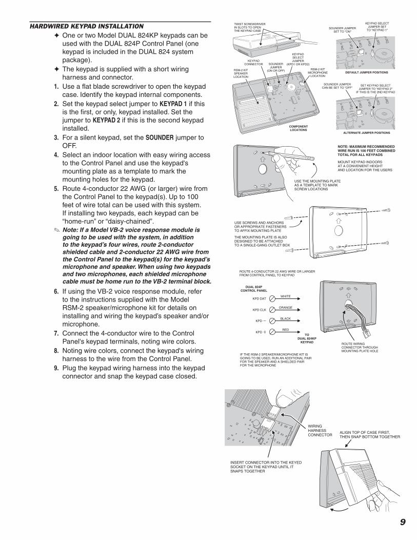
HARDWIRED KEYPAD INSTALLATION✦ One or two Model DUAL 824KP keypads can be
used with the DUAL 824P Control Panel (one keypad is included in the DUAL 824 system package).
✦ The keypad is supplied with a short wiring harness and connector.
1. Use a fl at blade screwdriver to open the keypad case. Identify the keypad internal components.
2. Set the keypad select jumper to KEYPAD 1 if this is the fi rst, or only, keypad installed. Set the jumper to KEYPAD 2 if this is the second keypad installed.
3. For a silent keypad, set the SOUNDER jumper to OFF.
4. Select an indoor location with easy wiring access to the Control Panel and use the keypad's mounting plate as a template to mark the mounting holes for the keypad.
5. Route 4-conductor 22 AWG (or larger) wire from the Control Panel to the keypad(s). Up to 100 feet of wire total can be used with this system. If installing two keypads, each keypad can be “home-run” or “daisy-chained”.
✎ Note: If a Model VB-2 voice response module is going to be used with the system, in addition to the keypad’s four wires, route 2-conductor shielded cable and 2-conductor 22 AWG wire from the Control Panel to the keypad(s) for the keypad’s microphone and speaker. When using two keypads and two microphones, each shielded microphone cable must be home run to the VB-2 terminal block.
6. If using the VB-2 voice response module, refer to the instructions supplied with the Model RSM-2 speaker/microphone kit for details on installing and wiring the keypad’s speaker and/or microphone.
7. Connect the 4-conductor wire to the Control Panel's keypad terminals, noting wire colors.
8. Noting wire colors, connect the keypad's wiring harness to the wire from the Control Panel.
9. Plug the keypad wiring harness into the keypad connector and snap the keypad case closed.
DEFAULT JUMPER POSITIONS
ALTERNATE JUMPER POSITIONS
TWIST SCREWDRIVERIN SLOTS TO OPEN THE KEYPAD CASE
RSM-2 KITSPEAKERLOCATION
KEYPADCONNECTOR SOUNDER
JUMPER(ON OR OFF)
KEYPADSELECTJUMPER
(KPD1 OR KPD2)
RSM-2 KITMICROPHONE
LOCATION
SOUNDER JUMPERSET TO "ON"
KEYPAD SELECTJUMPER SET
TO "KEYPAD 1"
SOUNDER JUMPERCAN BE SET TO "OFF"
SET KEYPAD SELECTJUMPER TO "KEYPAD 2"
IF THIS IS THE 2ND KEYPAD
COMPONENTLOCATIONS
NOTE: MAXIMUM RECOMMENDEDWIRE RUN IS 100 FEET COMBINEDTOTAL FOR ALL KEYPADS
MOUNT KEYPAD INDOORSAT A CONVENIENT HEIGHTAND LOCATION FOR THE USERS
USE THE MOUNTING PLATEAS A TEMPLATE TO MARKSCREW LOCATIONS
USE SCREWS AND ANCHORSOR APPROPRIATE FASTENERSTO AFFIX MOUNTING PLATE
THE MOUNTING PLATE IS ALSODESIGNED TO BE ATTACHEDTO A SINGLE-GANG OUTLET BOX
DUAL 824P
CONTROL PANEL
TO
DUAL 824KP
KEYPAD
IF THE RSM-2 SPEAKER/MICROPHONE KIT IS GOING TO BE USED, RUN AN ADDITIONAL PAIRFOR THE SPEAKER AND A SHIELDED PAIRFOR THE MICROPHONE
ROUTE WIRINGCONNECTOR THROUGHMOUNTING PLATE HOLE
KPD DAT
KPD CLK
KPD
KPD
WHITE
ORANGE
BLACK
RED
ROUTE 4-CONDUCTOR 22 AWG WIRE OR LARGERFROM CONTROL PANEL TO KEYPAD
WIRINGHARNESSCONNECTOR
INSERT CONNECTOR INTO THE KEYEDSOCKET ON THE KEYPAD UNTIL ITSNAPS TOGETHER
ALIGN TOP OF CASE FIRST,THEN SNAP BOTTOM TOGETHER

10
HARDWIRED LOOP WIRING✦ The DUAL 824 supports up to eight normally
open/closed hardwired loops each with 2.2K end-of-line resistor supervision.
✦ Each hardwired loop that is wired and programmed uses one sensor location.
✦ Each hardwired loop can be programmed to any sensor number.
✦ Each hardwired loop can be programmed as any sensor type, including arm/disarm toggle.
✦ Four COM terminals are shared as loop returns for the eight loops.
✦ Each hardwired loop has a 400 millisecond response time.
✎ NOTE: For UL installations, use UL Listed cable for all hardwired loop wiring.
1. Route wiring from the Control Panel to each hardwired switch contact, sensor, or device. Route the wires through the wiring slot or through a knockout for conduit wiring.
✎ NOTE: Maximum recommended hardwired loop length is 500 feet (250' out, and 250' back) for each loop. Maximum loop resistance (excluding the EOL resistor) is 100 ohms.
2. Connect the loop wires to LOOP # and COM terminals. For powered devices connect power wires to +12 VDC and any COM terminal.
3. On the sensor end, connect each normally closed sensor in series with the loop wires. Connect each normally open sensor in parallel with the loop wires. See wiring fi gure.
4. After the last sensor on the loop, connect a 2.2K end-of-line resistor across the loop.
✎ NOTE: Before the hardwired loops will function, they will need to be programmed. This will be covered in the Basic Control Panel Programming section of this manual.
ARM/DISARM KEY STATION WIRING✦ Any of the hardwired loops can be used with a
momentary keyswitch to arm and disarm the system.
1. Connect the loop as shown to the keyswitch and end-of-line resistor.
2. Connect an LED indicator from the switch plate to the H/A- and H/A+ terminals.
3. When programming the system, set the loop sensor function to “Type 9, Arm/Disarm Toggle” and set the Automation output to “Active while Armed”.
RUN LOOP WIRING BETWEEN THE CONTROL PANEL AND THE REMOTE HARDWIRED SENSORS
RUN 4-CONDUCTOR WIRETO POWERED DEVICES
RUN 2-CONDUCTOR WIRETO DEVICES NOT POWEREDFROM THE CONTROL PANEL
4-CONDUCTORFOR HARDWIRED
INFRAREDS
2-CONDUCTORFOR MAGNETIC
CONTACTS
LOOP
1
COM LOOP
2
LOOP
3
COM LOOP
4
LOOP
8
H/A
-
H/A
+
RLY
COM
RLY
N/C
RLY
N/O
COM
2.2K END-OF-LINERESISTOR FOREACH LOOP USED
NORMALLY CLOSEDSWITCHES (CONTACTS)
NORMALLY OPENSWITCHES (CONTACTS)
USE +12 VDC ANDANY COM TERMINALTO POWER EXTERNALDEVICES (1 AMP MAX.)
MAIN TERMINAL BLOCK+12
VDC
CONNECT EACH HARDWIRED INPUT TO A LOOP AND COM TERMINAL
FOR POWERED DEVICES, WIRE POWER LEADS TO +12 VDC AND ANY COMMON TERMINAL (OBSERVE POLARITY)
LOOP
1
COM LOOP
2
LOOP
3
COM LOOP
4
LOOP
8
H/A
-
H/A
+
RLY
COM
RLY
N/C
RLY
N/O
COM
NORMALLY CLOSED,SPRING RETURN, KEYSWITCH
470 OHM
KEYSTATION
2.2K OHM
LED
PROGRAM AUTOMATION OUTPUT FOR "ACTIVE WHILE ARMED"
LED WILL LIGHTWHEN SYSTEMIS ARMED
PROGRAM LOOP FOR ARM/DISARM TOGGLE (SENSOR TYPE 9)
MAIN TERMINAL BLOCK

11
EXTERNAL ALARM SIREN CONNECTION✦ An external siren alerts occupants and neighbors
with a loud siren during alarm.✦ Use a 12 volt, 1 amp maximum rated weather-
resistant horn speaker with a built-in siren driver. Do not use a plain speaker without a siren driver.
✎ NOTE: Connection of an electromechanical bell or motor bell is not recommended because of the radio interference generated when the bell is running.
✎ UL NOTE: Only one external siren is allowed in UL installations.
1. Mount the external siren.2. Route the wires from the external siren to the
Control Panel.3. Route the siren wires up through the wiring access
slot or through a knockout when using conduit.4. Connect a jumper wire from the +12 VDC terminal
to the RLY COM terminal.5. Connect the positive siren wire to the RELAY
N/O terminal.6. Connect the negative siren wire to one of the
COM terminals.✎ NOTE: The relay contacts are isolated. Use the
RLY N/O & RLY COM terminals alone to switch an externally powered load.
TELEPHONE LINE CONNECTION ✦ Connect the Control Panel to the telephone
line if the system is monitored, requires 2-way audio, telephone remote command, or for remote programming with RA-2400 software.
✦ Telephone RING & TIP terminals are for connection to the incoming telephone line.
✦ Seized telephone ring & tip (R1 & T1) are for connection to local telephone sets. When the communicator activates, all the local telephone sets will be disconnected to prevent an off-hook telephone on the premises from blocking the communicator call.
1. Install a USOC RJ31-X or RJ38-X jack to the telephone system near the Control Panel.
2. Route an appropriate modular telephone line cord from the jack to the Control Panel.
3. Route the line cord through the Control Panel's wiring access slot or through a knockout for conduit wiring.
4. Connect the incoming telephone line wires to the Control Panel's telephone terminal block TIP and RING terminals.
5. Connect the local telephone set wires to the Control Panel's telephone terminal block T1 and R1 terminals.
✦ When directly connecting (without a telephone line) to the DUAL 824 with the RA-2400 remote access software (Version 1.3 or later), disconnect the incoming telephone line and connect the modem to the panel's TIP and RING terminals (with the modem's red & green phone line wires). Press the EMERGENCY key while in Test Mode to cause the panel to connect to the modem.
LOOP
8
H/A
-
H/A
+
RLY
COM
RLY
N/C
RLY
N/O
COM
EXTERNAL SIREN12 VDC 1 AMP
MAXIMUM
EXTERNAL
ALARM RELAY
12 VDC, 1 AMP
MAXIMUM
INSTALL WIREJUMPER TO PROVIDEPOWER TO RELAYCONTACTS
+12
VDC
MAIN TERMINAL BLOCK
CONNECT EXTERNALSIREN TO ALARM RELAYTERMINALS
INSTALL A JUMPERWIRE BETWEEN THE+12 VDC AND RLY COMTERMINALS
SEIZEDRING (R1)
SEIZEDTIP (T1)
LINERING (R)
LINETIP (T)
GRAY
RED
T
R T1
R1
� �� � � � �
TO LOCALTELEPHONESETS
TO TELEPHONENETWORK
8-POSITION
USOC RJ31-X
(OR RJ38-X)
JACK
�� � �
SHORTING BARSHORT REMOVEDON PLUG INSERTION
8-PIN
MODULAR
PHONE CORD
DUAL 824P
TELEPHONE
TERMINAL
BLOCK
GREEN
BROWN
BLUE, ORANGE BLACK, AND YELLOW NOT USED
TELEPHONE TERMINAL BLOCK
CONNECT INCOMMING ANDOUTGOING TELEPHONE LINESTO THE TELEPHONE TERMINAL BLOCK
TELEPHONETERMINAL
BLOCK
EXTERNALALARMSIREN

12
AUTOMATION OUTPUT CONNECTION ✦ The Control Panel provides a Automation Output
to control lights, devices and appliances.✦ Automation Output can connect to most popular
home automation devices and other simple electronic devices (see fi gure).
✦ Press to turn the Automation Output on, press again to turn it off.
Programmable Options
✦ There are many programmable options for the Automation Output.
✦ The Automation Output can be programmed for a variety of useful functions, such as: fl ashing during alarm, fl ashing after an alarm, on while armed, or, on during exit/entry delays.
✦ See the “Advanced Programming” section of this manual for details on changing the function of the Automation Output.
VOICE RESPONSE MODULE✦ The DUAL 824P circuit board has a plug-in
location for a Model VB-2 voice response module.✦ The VB-2 module allows remote command
of the system locally and remotely through a pushbutton telephone.
✎ NOTE: The following two features require a Model RSM-2 speaker/microphone kit installed in the keypad.
✦ The VB-2 module can sound voice prompts through a speaker installed in the keypad.
✦ The VB-2 module supports listen-only audio, two-way manual audio, and full duplex two-way audio communication with the Central Station through a microphone installed in the keypad.
✎ NOTE: Refer to the VB-2 instructions for details on operating the voice response module.
Voice Response Module Installation
1. Identify the audio module components, noting the terminal block positions.
2. Connect shielded microphone wire to the VB-2 MICROPHONE COMMON (for shield) and MICROPHONE #1 (for center conductor) terminals. Connect the other end of the wire’s shield to the BLACK, and center conductor to the RED microphone wires in the keypad.
3. If using two keypads for audio monitoring, repeat Step 2 for the second keypad, except connect the center conductor to the VB-2 MICROPHONE #2 terminal.
4. WITHOUT POWER APPLIED TO THE CONTROL PANEL, plug the voice response module into the sockets on the Control Panel's circuit board. Be sure the arrows on the module board are pointing up.
5. Connect 2-conductor wire from the Control Panel’s KPD SPK+ and KPD SPK- terminals to the two speaker wires in the keypad.
LOOP
8
H/A
-
H/A
+
RLY
COM
MAIN TERMINAL BLOCK
ANY SENSOR CANBE PROGRAMMEDTO TOGGLETHE AUTOMATIONOUTPUT
PRESS THE KEY ON ANYSYSTEM KEYPADTO TOGGLE THEAUTOMATIONOUTPUT
A
THE POSITIVE H/A TERMINAL PROVIDES +12 VOLTS DC AND IS CURRENT LIMITED AT 40 MILLIAMPS MAXIMUM
THE NEGATIVE H/A TERMINAL WILL SWITCH TO GROUND WHEN AUTOMATION OUTPUT IS ACTIVATED
X-10BURGLAR ALARMINTERFACE(CAN CONTROLHOUSE LIGHTSTHROUGH X-10SYSTEM)
X-10LINEAR RB-90RELAY MODULE
YOURLOAD
POWERSOURCE
LIGHTEMITTINGDIODE(L.E.D.)
EXAMPLE AUTOMATION OUTPUT HOOK-UPS
H/A +H/A -H/A +H/A -H/A +H/A -
470 O
HM
MICROPHONE
TERMINALS MICROPHONE #1 (+)
MICROPHONE COMMON (-)
MICROPHONE #2 (+)
MICROPHONE
DIGITAL VOICEVOLUME CONTROL
MODULE-TO-CONTROLPANEL CONNECTOR
MODULE-TO-CONTROLPANEL CONNECTOR
VB-2 VOICE RESPONSE MODULE
CAREFULLY PLUG VOICE MODULEINTO THE TWO CIRCUIT BOARD SOCKETS
BE SURE ALLPINS ARE ALIGNED
BOARD ARROWSPOINT UP
BE SURE CONTROL PANEL POWER IS DISCONNECTED!

13
CONTROL PANEL POWER CONNECTION✦ The Control Panel is powered by a low voltage
plug-in transformer.✦ Use up to 25 feet of 20 AWG or larger
2-conductor wire to connect the transformer to the Control Panel.
1. Route the power wires from the plug-in transformer to the Control Panel.
2. Connect the wires to the transformer terminals (do not plug the transformer in until the wiring is complete).
3. Route the power wires through the Control Panel's wiring access slot or through a knockout for conduit wiring.
4. Connect the power wires from the transformer to the Control Panel's main terminal block AC & AC terminals.
5. Plug transformer into an unswitched AC outlet.6. Secure transformer with screw to prevent
unplugging.
BACKUP BATTERY INSTALLATION ✦ A 12-volt backup battery may be installed and is
highly recommended.✦ The backup battery will power the system for up
to 6 hours during AC power loss.✦ The backup battery is automatically charged by
the Control Panel when AC power is present.✦ A low backup battery will cause the keypad's
POWER indicator to fl ash as it is being charged.1. Position the battery as shown.2. Connect the black battery lead to the negative
battery terminal.3. Connect the red battery lead to the positive
battery terminal.✎ WARNING: DO NOT REVERSE THE BATTERY
LEADS! THE BATTERY FUSE WILL BLOW.
KPD
CLK
KPD
DAT
KPD
SPK +
KPD
SPK-AC AC
KPD
-
MAIN TERMINAL BLOCK
XFRMRKEYPAD
PLUG-IN TRANSFORMER16 VAC, 28 VABE SURE TO SELECT AN
UN-SWITCHED AC OUTLETFOR THE TRANSFORMER
CONNECTTRANSFORMER WIRESTO THE AC TERMINALSON THE MAIN TERMINALBLOCK
TRANSFORMER
115 VACOUTLET
PLUG TRANSFORMERINTO 115 VAC OUTLETTHAT IS NOT CONTROLED BY A LIGHT SWITCH
SCREW
AFTER ALL WIRING IS COMPLETE,CONNECT THE BACKUP BATTERY
BE SURE RED WIRE ATTACHESTO POSITIVE (+) TERMINAL, ANDBLACK WIRE ATTACHES TONEGATIVE (-) TERMINAL

14
✦ In a new installation, when power is fi rst applied the system's master user code is “1234”.
CREATE THE MASTER USER CODE✎ NOTE: Local programming must be entered on
the system's hardwired keypad, not on a wireless keypad.
1. Press (clears keypad if any other keys have been pressed).
2. Place the system in Test Mode (enter 1234 and press TEST.✴ A “gong” and four “beeps” will sound.
3. Enter the Setup Mode from Test Mode, enter 1234 then press TEST again.✴ A “gong” and fi ve “beeps” will sound. The system is now
in Test Mode.4. Enter 99 then press HOME.5. Enter any combination of 1-5 digits for the master
user code, then press AWAY.✎ NOTE: For maximum security, a three to fi ve digit
code is recommended.
6. Press and hold the OFF key for 3 seconds to exit program mode.
7. Test the new master user code by entering it then pressing TEST.
8. Log the master user code in the box below.
✎ NOTE: The master user code can be used to enter Setup Mode. The restricted user codes cannot. To create restricted user codes, see the “Advanced Programming” section of this manual.
7. BASIC CONTROL PANEL PROGRAMMING
MASTER USER CODE:
START IN SETUP MODE
PROGRAMMINGSTEP #99
ENTERS STEPNUMBER
NEWMASTERUSERCODE
STORESNEW CODE
DONE
SETTING ANEW MASTERUSER CODE
HOLD FOR3 SECONDSTO EXITSETUP
START IN OFF MODE
CLEARSKEYPAD
DEFAULTMASTERUSERCODE
1 GONG &4 BEEPS(TEST MODE)
DEFAULTMASTERUSERCODE
1 GONG &5 BEEPS(SETUP MODE)
ENTERINGSETUPMODE

15
PROGRAM THE HARDWIRED LOOPS✦ Each hardwired loop used must be programmed
into the Control Panel's memory.✦ Each hardwired loop programmed uses one of
the twenty four available sensor locations.1. Start with the system in Test Mode (enter the
master user code and press TEST).2. Enter the Setup Mode from Test Mode, enter the
master user code then press TEST again.✴ A “Gong” and fi ve “Beeps” will sound. The system is now
in Setup Mode.✴ The sensor status indicators will light for any sensors
already programmed into the Control Panel.3. Enter programming Step #301-308 (301=loop 1,
302=loop 2, etc.) for the hardwired loop desired.4. Press HOME to select step.5. Enter an unused sensor number from 01-24 for
the loop (you must enter two digits, example: 5 = 05).
6. Press AWAY to store.✴ A single “Bing” tone will sound and the sensor status
indicator for that sensor will stay lit. A double “Buzz” will sound if that sensor location is already in use.
7. Repeat Steps 3-6 to enable all of the hardwired loops used.
✎ NOTE: The default sensor function for the hardwired loops is Perimeter (Type 5). Any sensor function can be selected for each hardwired loop, refer to the “Customizing the System” section of this manual.
PROGRAM THE WIRELESS SENSORS✦ Each wireless sensor used must be programmed
into the system’s memory. See the next two pages for details on activating different models of transmitters.
✦ Each wireless sensor programmed uses one of the twenty four available sensor locations.
1. Start with the system in Test Mode (enter any user code and press TEST).
2. Enter the Setup Mode from Test Mode, enter the master user code then press TEST again.✴ A “Gong” and fi ve “Beeps” will sound. The system is now
in Setup Mode.✴ The sensor status indicators will light for any sensors
programmed into the Control Panel.3. Enter an unused sensor number from 01-24 (you
must enter two digits, example: 5 = 05).✴ The sensor indicator light will fl ash for the sensor number
selected.4. Activate the sensor by sending a test or alarm
signal (be sure the sensor's battery is connected or that its battery protection strip is removed).✴ A single “Bing” tone will sound and the sensor status
indicator for that sensor will stay lit. A “Buzz” will sound if that sensor location is already in use.
5. Repeat Steps 3 & 4 for each additional sensor, or exit Setup Mode by pressing the OFF button for three seconds.
START IN TEST
MASTERUSERCODE
1 GONG & 5 BEEPS(SETUP MODE)
STEP #301-308FOR LOOP #1-8
ENTERS STEPNUMBER
STORES LOOPSENSOR NUMBER1 BING
SENSORNUMBER (01-24)FOR LOOP
DONE
START IN TEST
MASTERUSERCODE
1 GONG & 5 BEEPS(SETUP MODE)
NEW SENSORNUMBER
1 BING ANDSENSORINDICATORLIGHTS
REPEAT OR EXIT
ACTIVATESENSOR
SENSORINDICATORFLASHES

16
PROGRAMMING DIFFERENT SENSOR TYPES✦ Follow the instructions on the previous page to
select a sensor number to program the sensor into.
✎ NOTE: A sensor can be programmed into more than one location. Be sure to choose an UNUSED sensor number. If a sensor gets entered into more than one location, delete the duplicates using the remove sensor function.
✦ To add DXS-10 wireless keypads, press and hold the keypad's key until programmed into the Control Panel.
✦ For DXS-31 and DXS-32 door/window sensors, move the magnet away from the side of the sensor.
✎ IMPORTANT NOTE: The DXS-31 & DXS-32 door/window sensors are pre-set at the factory for delayed burglary response. If the sensor is going to be used on a non-entry portal (window, sliding glass door, etc.) a jumper can be changed in the sensor to select instant response. The jumper should be changed before programming the sensor so the Control Panel will assign the sensor to the proper sensor function. See the “Basic Sensor Installation” section of this manual or the sensor’s instructions for details on changing the jumper.
✦ For DXS-81, DXS-91, DXS-54, DXS-73, & accessory sensors, simply send a test transmission (refer to the sensor's instructions for details on sending a test transmission).
DXS-10
DXS-32
DXS-81
17
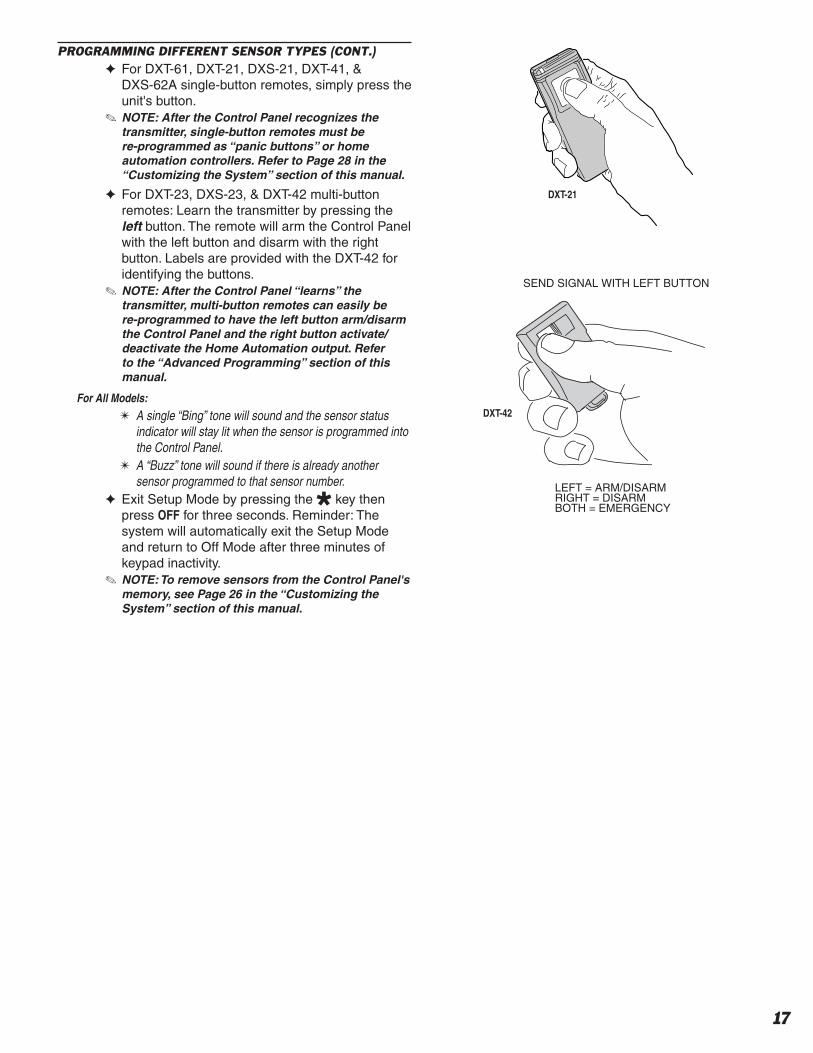
PROGRAMMING DIFFERENT SENSOR TYPES (CONT.)✦ For DXT-61, DXT-21, DXS-21, DXT-41, &
DXS-62A single-button remotes, simply press the unit's button.
✎ NOTE: After the Control Panel recognizes the transmitter, single-button remotes must be re-programmed as “panic buttons” or home automation controllers. Refer to Page 28 in the “Customizing the System” section of this manual.
✦ For DXT-23, DXS-23, & DXT-42 multi-button remotes: Learn the transmitter by pressing the left button. The remote will arm the Control Panel with the left button and disarm with the right button. Labels are provided with the DXT-42 for identifying the buttons.
✎ NOTE: After the Control Panel “learns” the transmitter, multi-button remotes can easily be re-programmed to have the left button arm/disarm the Control Panel and the right button activate/deactivate the Home Automation output. Refer to the “Advanced Programming” section of this manual.
For All Models:
✴ A single “Bing” tone will sound and the sensor status indicator will stay lit when the sensor is programmed into the Control Panel.
✴ A “Buzz” tone will sound if there is already another sensor programmed to that sensor number.
✦ Exit Setup Mode by pressing the key then press OFF for three seconds. Reminder: The system will automatically exit the Setup Mode and return to Off Mode after three minutes of keypad inactivity.
✎ NOTE: To remove sensors from the Control Panel's memory, see Page 26 in the “Customizing the System” section of this manual.
DXT-21
SEND SIGNAL WITH LEFT BUTTON
LEFT = ARM/DISARMRIGHT = DISARMBOTH = EMERGENCY
DXT-42
18
✦ Each accessory sensor is packaged with its own set of installation instructions specifi c to the model of sensor.
✦ Refer to the sensor's instructions for details on installing, operating, and testing of the sensor.
✦ Following are basic instructions for installing two popular DUAL 824 accessories: The Model DXS-10 Wireless Remote Keypad and the Model DXS-31 & DXS-32 Door/Window Transmitters.
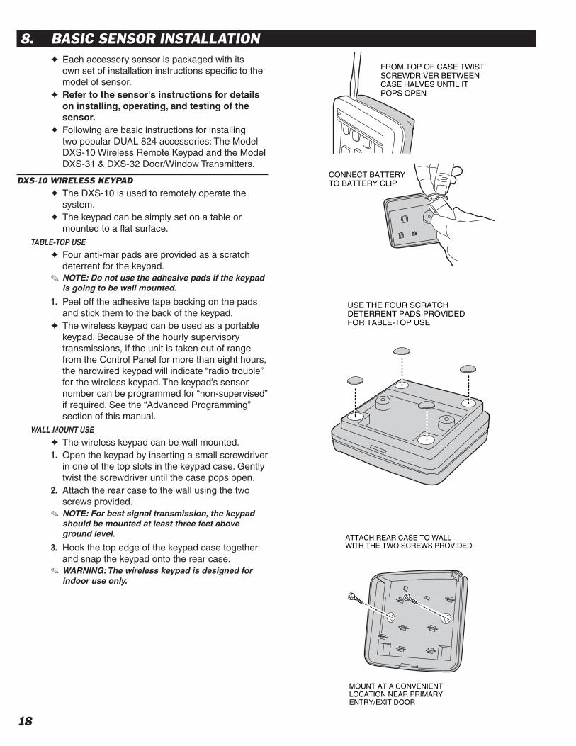
DXS-10 WIRELESS KEYPAD✦ The DXS-10 is used to remotely operate the
system.✦ The keypad can be simply set on a table or
mounted to a fl at surface.TABLE-TOP USE
✦ Four anti-mar pads are provided as a scratch deterrent for the keypad.
✎ NOTE: Do not use the adhesive pads if the keypad is going to be wall mounted.
1. Peel off the adhesive tape backing on the pads and stick them to the back of the keypad.
✦ The wireless keypad can be used as a portable keypad. Because of the hourly supervisory transmissions, if the unit is taken out of range from the Control Panel for more than eight hours, the hardwired keypad will indicate “radio trouble” for the wireless keypad. The keypad's sensor number can be programmed for “non-supervised” if required. See the “Advanced Programming” section of this manual.
WALL MOUNT USE
✦ The wireless keypad can be wall mounted.1. Open the keypad by inserting a small screwdriver
in one of the top slots in the keypad case. Gently twist the screwdriver until the case pops open.
2. Attach the rear case to the wall using the two screws provided.
✎ NOTE: For best signal transmission, the keypad should be mounted at least three feet above ground level.
3. Hook the top edge of the keypad case together and snap the keypad onto the rear case.
✎ WARNING: The wireless keypad is designed for indoor use only.
8. BASIC SENSOR INSTALLATION
CONNECT BATTERYTO BATTERY CLIP
FROM TOP OF CASE TWISTSCREWDRIVER BETWEENCASE HALVES UNTIL IT POPS OPEN
USE THE FOUR SCRATCHDETERRENT PADS PROVIDEDFOR TABLE-TOP USE
ATTACH REAR CASE TO WALLWITH THE TWO SCREWS PROVIDED
MOUNT AT A CONVENIENTLOCATION NEAR PRIMARY ENTRY/EXIT DOOR

19
DXS-31 & DXS-32 DOOR/WINDOW SENSORS✦ The DXS-31 and DXS-32 sensors can be used
to monitor doors, windows, cabinets, crawl space doors, gates, freezer doors, and many other moving objects that could be used for intrusion or need to be monitored.
✦ A built-in magnetic switch triggers the sensor when its magnet (mounted on the moving part or the door or window) moves away from the sensor.
✦ The DXS-31 sensor can be wired to external normally closed switches for remote triggering.
✦ The DXS-31 sensor can connect directly to a glass break detector.
SET SENSOR JUMPER
✦ A jumper inside the door/window sensor selects instant or delayed response.
1A. If the sensor is going to be used on the primary entry/exit door make sure that the jumper is in the DELAY position.
1B. If the sensor is going to be used on a window or a door that is not going to be used to enter and exit the premises, set the jumper to the INSTANT position.
CHOOSE MOUNTING METHOD
2A. Apply double-stick tape (supplied) to back of sensors and magnets.
2B. Screws are also provided to mount sensors and magnets. Screws are preferred over the double-stick tape in permanent installations.
✎ UL NOTE: Double-stick tape is not allowed in UL installations.
ATTACH SENSORS AND MAGNETS
✦ Allow a maximum of 1/2" between magnet and sensor when door/window is closed.
✦ The magnet height is adjustable and an optional magnet spacer is provided for uneven surfaces.
3A. On doors, mount sensor to door frame and magnet to door.
3B. On windows, mount sensor to window frame and magnet to window.
✎ NOTE: Magnet must line up with mark on sensor case both horizontally & vertically.
4. Snap sensor onto mounting plate.
TEST SENSORS✴ In Chime Mode, the hardwired keypad(s) should “ding-
dong” when the sensor sends a signal.5. Open door or window.
✴ Verify that light on the sensor (if there is one) glows momentarily when door/window is opened.
✴ Status indicator on the hardwired keypad(s) should remain lit for each door/window sensor that is left open.
TRANSMITTERMOUNTED ONDOOR JAMB
(NOTE: SMALL ENDOF TRANSMITTER UP)
(NOTE: SMALL ENDOF TRANSMITTER DOWN)
MAGNETMOUNTEDON DOOR
MAGNET MOUNTEDON DOOR
TRANSMITTERMOUNTED ONWINDOW SILL
MAGNET MOUNTEDON WINDOW FRAME
SLIDING WINDOWLEFT OPENING DOOR
RIGHT OPENING DOOR
TRANSMITTERMOUNTED ONDOOR JAMB
TRANSMITTERMOUNTED ONWINDOW FRAME
MAGNETMOUNTEDON WINDOWSASH STILE
DOUBLE-HUNG
WINDOW
EXAMPLE INSTALLATIONS (WITH DXS-31 SHOWN)
TRANSMITINDICATOR
INPUTSELECTJUMPER
INSTANT/DELAYOPTION JUMPER
ANTENNA
MAGNETALIGNMENTMARK
TWO TYPE 2032BATTERIES
BATTERY CLAMP
EXTERNALINPUTTERMINALS
TESTSWITCH
BATTERYCLAMPSCREW
INSTANT/DELAY
OPTION JUMPER
SELECTSDELAY
SELECTSINSTANT
ATTACH MOUNTING PLATESUSING THE SCREWS ORDOUBLE-STICK TAPE PROVIDED
NOTE: ATTACHING THE TRANSMITTER WITH DOUBLE-STICK
TAPE IS NOT ALLOWED IN UL INSTALLATIONS
ACTIVATE TRANSMITTER BY OPENING DOOR OR WINDOW
REPLACE TRANSMITTER COVER WHEN FINISHED
NOTE: THE TRANSMIT
INDICATOR WILL ONLY LIGHT
DURING TRANSMISSIONS
WHEN THE CASE IS OPEN
(EXCEPT WHEN PUSHING
THE CASE FOR TESTING)
OPEN DOOR, TRANSMITINDICATOR SHOULD LIGHT

20
✦ The system can be customized for the specifi c installation.
✦ A label sheet with sensor location names is provided with DUAL 824KP keypads.
✦ Labeling the sensors allows quick and easy identifi cation of where a door or window is open, where any alarms have occurred, where a sensor with a low battery is, or where a sensor with trouble is.
LABELING THE SENSOR LOCATIONS1. Open the keypad's plastic beauty cover to reveal
the sensor identifi cation label area.2. Open one protected door/window to light its
sensor status light on the keypad(s).3. Choose a label that describes the sensor
location, or write the location on a blank label, and stick it in the area next to the sensor number.
4. Close the protected opening that you just labeled.
5. Repeat for each protected opening.6. Stick the WIRELESS KEYPAD label in the sensor
number location for the wireless keypad (if used).7. Close the beauty cover when fi nished.
9. CUSTOMIZING THE KEYPAD
PULL TAB TOOPEN BEAUTYCOVER
OPEN DOOR OR WINDOW TO LIGHT SENSOR STATUS INDICATOR ON KEYPAD(S)
USE SENSORLABELS SUPPLIEDTO IDENTIFY EACHSENSOR LOCATION
USE AN INK PEN TOCUSTOMIZE BLANKLABELS
APPLY THE PRE-PRINTED SENSORLOCATION LABELS TO SUIT THEINSTALLATION
BLANK LABELS THAT CAN BE FILLED INWITH AN INK PEN ARE ALSO PROVIDEDFOR CUSTOM SENSOR IDENTIFICATION
21
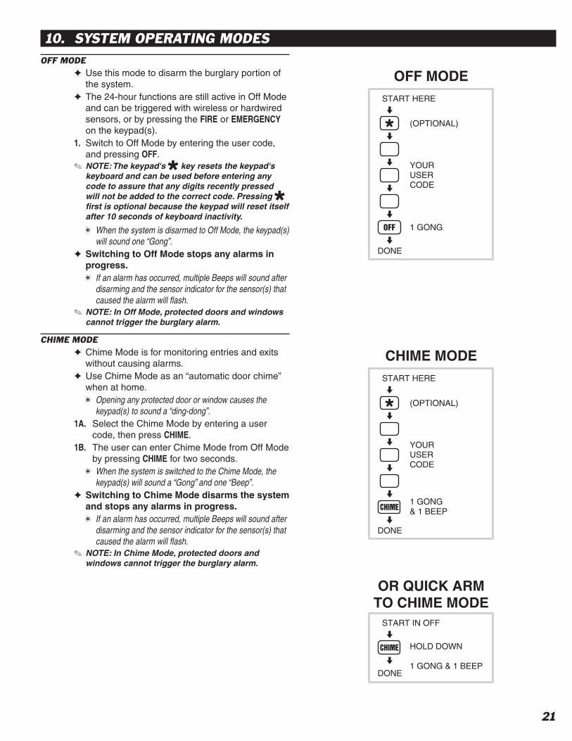
OFF MODE✦ Use this mode to disarm the burglary portion of
the system.✦ The 24-hour functions are still active in Off Mode
and can be triggered with wireless or hardwired sensors, or by pressing the FIRE or EMERGENCY on the keypad(s).
1. Switch to Off Mode by entering the user code, and pressing OFF.
✎ NOTE: The keypad's key resets the keypad's keyboard and can be used before entering any code to assure that any digits recently pressed will not be added to the correct code. Pressing fi rst is optional because the keypad will reset itself after 10 seconds of keyboard inactivity.
✴ When the system is disarmed to Off Mode, the keypad(s) will sound one “Gong”.
✦ Switching to Off Mode stops any alarms in progress.✴ If an alarm has occurred, multiple Beeps will sound after
disarming and the sensor indicator for the sensor(s) that caused the alarm will fl ash.
✎ NOTE: In Off Mode, protected doors and windows cannot trigger the burglary alarm.
CHIME MODE✦ Chime Mode is for monitoring entries and exits
without causing alarms.✦ Use Chime Mode as an “automatic door chime”
when at home.✴ Opening any protected door or window causes the
keypad(s) to sound a “ding-dong”.1A. Select the Chime Mode by entering a user
code, then press CHIME.1B. The user can enter Chime Mode from Off Mode
by pressing CHIME for two seconds.✴ When the system is switched to the Chime Mode, the
keypad(s) will sound a “Gong” and one “Beep”.✦ Switching to Chime Mode disarms the system
and stops any alarms in progress.✴ If an alarm has occurred, multiple Beeps will sound after
disarming and the sensor indicator for the sensor(s) that caused the alarm will fl ash.
✎ NOTE: In Chime Mode, protected doors and windows cannot trigger the burglary alarm.
10. SYSTEM OPERATING MODES
START HERE
(OPTIONAL)
YOURUSERCODE
1 GONG
DONE
OFF MODE
START HERE
(OPTIONAL)
YOURUSERCODE
1 GONG& 1 BEEP
DONE
CHIME MODE
START IN OFF
HOLD DOWN
1 GONG & 1 BEEPDONE
OR QUICK ARMTO CHIME MODE

22
HOME MODE✦ Use this mode when sleeping or when anyone is
staying inside.✦ Home Mode causes an instant alarm when any
perimeter sensor is triggered.✦ Home Mode causes a delayed alarm when any
exit/entry sensor is triggered (except in Home Instant Mode when they are instant).
✦ Each burglary sensor can trigger the siren once per arming period.
✦ Alarm siren stops automatically after fi ve minutes and the system will remain armed.
✦ Home Mode ignores all interior sensors (motion detectors, etc.).
1A. Arm to Home Mode by entering a user code, and pressing HOME.
1B. The user can “Quick Arm” to Home Mode from Off or Chime Mode by pressing HOME for two seconds. (Quick arming can be disabled; see the “Advanced Programming” section of this manual.)
✴ When the system is armed to the Home Mode, the keypad(s) will sound a “Gong” and two “Beeps”.
2. Enter a user code and press OFF or CHIME to disarm from Home Mode and/or stop the alarm siren.✴ If an alarm has occurred, multiple Beeps will sound after
disarming and the sensor indicator for the sensor(s) that caused the alarm will fl ash (switch to Off Mode again or re-arm the system to stop the fl ashing alarm memory).
SECURE EXIT1. If the system is already in the Home Mode and
the user wants to exit the premises while leaving someone inside with the system still in Home Mode, enter a user code and press the HOME key.✴ The HOME light will blink for 60 seconds. No exit delay
Beeps will sound during the Exit Delay.2A. The user can leave through a door with a
delayed perimeter sensor during the 60 second Exit Delay without causing the Control Panel to begin an Entry Delay.
2B. Re-entering during the silent Exit Delay will extend the Exit Delay another 60 seconds (one time only).
✎ NOTE: The Exit Delay time can be changed; see the “Advanced Programming” section of this manual.
HOME INSTANT MODE1. If the system is already in the Home Mode and
the user wants to make all exit/entry sensors instant, press HOME for two seconds.✴ Two “Gongs” and two “Beeps” will sound and the HOME
light and ARMED indicator will blink continuously.2. Because all exit/entry sensors will now cause an
instant alarm when in Home Mode, the system must be disarmed before opening any exit/entry delay door.
✎ NOTE: If quick arming is disabled the Home Instant Mode is unavailable.
MANUAL BYPASSING OF SENSORS✦ Manual bypassing of sensors in the Home Mode
allows arming of the system at night with open windows, while still having perimeter protection with other closed doors and windows.
✦ If the READY indicator is lit, all sensors are closed.1. If the READY indicator is not lit, the system will
resist arming because of open door or window sensors.✴ Four high-low Beeps to warn the user that something is
open and the system will remain in the previous mode.✴ Lit sensor status indicators show which sensors are
open.2. To manually bypass the open sensors, arm the
system again within fi ve seconds.✴ A “Gong” and two “Beeps” will sound, the HOME
indicator will light, and the open sensors will be bypassed.
✎ WARNING: Bypassed sensors cannot cause an alarm. Closing the sensor removes the bypass.
START IN OFF OR CHIME MODE
(OPTIONAL)
YOURUSERCODE
1 GONG& 2 BEEPS
DONE
HOME MODE
START IN OFFOR CHIME MODE
HOLD DOWN
1 GONG & 2 BEEPSDONE
OR QUICK ARMTO HOME MODE
START IN HOME MODE
(OPTIONAL)
YOURUSERCODE
1 GONG& 2 BEEPS
DONE
SECURE EXIT
START IN HOME MODE
HOLD DOWN
1 GONG & 2 BEEPSDONE
HOME INSTANTMODE

23
AWAY MODE✦ Use this mode when no one will be staying home.✦ Away Mode causes an instant alarm when any
perimeter sensor is triggered.✦ Away Mode causes a delayed alarm when any
exit/entry sensor is triggered.✦ Away Mode causes an instant alarm when any
interior sensors (motion detectors, etc.) are triggered. The interior sensors will be delayed if a perimeter delayed sensor is triggered fi rst.
✦ Each burglary sensor can trigger the siren once per arming period.
✦ Alarm siren stops automatically after fi ve minutes and the system will remain armed.
1A. Arm to Away Mode by entering a user code, and pressing AWAY.
1B. The user can “Quick Arm” to Away Mode from Home, Chime or Off Mode by pressing AWAY for two seconds. (Quick arming can be disabled; see the “Advanced Programming” section of this manual.)
EXIT DELAY (For Leaving the Premises)✴ When the system is armed to the Away Mode, the
keypad(s) will sound a “Gong” and three “Beeps”.✴ During the 60 second Exit Delay, the keypad(s) will
sound “Beeps” (double Beeps last 10 seconds) and the AWAY and ARMED indicators will blink.
2A. The Exit Delay gives the user 60 seconds to leave the premises through an exit/entry door without triggering an alarm.
2B. Re-entering during the Exit Delay will extend the Exit Delay another 60 seconds (one time only).
✴ When the Exit Delay is over, the keypad(s) will sound one “Gong” to warn the user that the system is fully armed and the ARMED indicator will light steady.
✎ NOTE: The Exit Delay time can be changed; see the “Advanced Programming” section of this manual.
ENTRY DELAY (For Entering the Premises)3A. The Entry Delay gives the user 30 seconds to
enter the premises through an exit/entry door without triggering an alarm.
3B. If a exit/entry sensor is triggered, starting the Entry Delay, the interior sensors will also become delayed (this allows motion in the premises during the Entry Delay).
✴ During the 30 second Entry Delay, the keypad(s) will sound “Beeps”.
4. When the Entry Delay is over, the system will go into full alarm and sound the siren if it is not disarmed to the Off or Chime Mode.✴ If an alarm has occurred while the user was gone,
multiple Beeps will sound after disarming and the sensor light for the sensor(s) that caused the alarm will fl ash (switch to Off Mode again or re-arm the Control Panel to stop the fl ashing alarm memory).
✎ NOTE: The Entry Delay time can be changed; see the “Advanced Programming” section of this manual.
MANUAL BYPASSING OF SENSORS✦ Manual bypassing of sensors in the Away Mode
allows arming of the system with open doors and windows, while still having perimeter protection with other closed doors and windows.
✦ If the READY indicator is lit, all sensors are closed.1. If the READY indicator is not lit, the system will
resist arming because of open door or window sensors.✴ Four high-low Beeps to warn the user that something is
open and the system will remain in the previous mode.✴ Lit sensor status indicators show which sensors are
open.2. To manually bypass the open sensors, arm the
system again within fi ve seconds.✴ A “Gong” and three “Beeps” will sound, the AWAY
indicator will light, and the open sensors will be bypassed.
✎ WARNING: Bypassed sensors cannot cause an alarm. Closing the sensor removes the bypass.
START IN OFF, CHIME OR HOME MODE
(OPTIONAL)
YOURUSERCODE
1 GONG& 3 BEEPS
DONE
AWAY MODE
HOLD DOWN
1 GONG & 3 BEEPSDONE
OR QUICK ARMTO AWAY MODE
START IN OFF, CHIME OR HOME MODE

24
TEST MODE✦ Even though this is a self-monitoring supervised
system, the National Burglar and Fire Alarm Association recommends that all security systems be tested manually on a regular basis.
1. The system must be in Off Mode before switching to Test Mode.
2. Switch the system into Test Mode by entering a user code and pressing TEST.✴ When the system is switched to the Test Mode, the
keypad(s) will sound a “Gong” and four “Beeps”.3. Holding down the TEST button in Test Mode will
light all of the keypad’s indicators.✴ The sensor status indicators will fl ash for each sensor
programmed into the Control Panel.4. Go to each sensor and press its test button or
open and close the protected opening.5. To test the wireless keypad, press the wireless
keypad’s key.✴ The keypad(s) will make a “Bing” sound as each sensor
is tested, followed by 1-3 beeps indicating signal strength with 3 beeps being the strongest signal.
✴ As each sensor is tested, the sensor status indicator for the sensor will stop fl ashing and return to showing the current status of the sensor.
6. Continue testing until there are no fl ashing sensor status indicators.
SENSOR OPERATION IN EACH SYSTEM MODE
SENSOR FUNCTION OFF MODE CHIME MODE HOME MODE AWAY MODE
AUTOMATION ACTIVATES AND DEACTIVATES THE AUTOMATION OUTPUT
EMERGENCY ARMED 24-HOURS - TRIGGERS EMERGENCY ALARM
PANIC ARMED 24-HOURS - TRIGGERS SILENT PANIC ALARM
FIRE ARMED 24-HOURS - TRIGGERS FIRE ALARM
PERIMETER DEACTIVATED CHIME INSTANT BURGLARY ALARM
EXIT/ENTRY DEACTIVATED CHIME DELAYED BURGLARY ALARM
INTERIOR DEACTIVATED DEACTIVATED DEACTIVATEDINSTANT BURGLARY ALARM UNLESS
ACTIVATED DURING AN ENTRY DELAY, THEN IT IS DELAYED
CHIME CHIME
2-BUTTON ARM/DISARM (LEFT)2-BUTTON AUTOMATION (RIGHT)EMERGENCY (BOTH BUTTONS)
LEFT BUTTON SWITCHES SYSTEM TO AWAY MODE †IF ALARM MEMORY IS ACTIVE, SWITCHES SYSTEM TO OFF MODE ‡ LEFT BUTTON SWITCHES SYSTEM TO OFF MODE ‡
2-BUTTON ARM (LEFT)2-BUTTON DISARM (RIGHT)EMERGENCY (BOTH BUTTONS)
LEFT BUTTON SWITCHES SYSTEM TO AWAY MODE †IF ALARM MEMORY IS ACTIVE, SWITCHES SYSTEM TO OFF MODE ‡ RIGHT BUTTON SWITCHES SYSTEM TO OFF MODE ‡
ENVIRONMENTAL ARMED 24-HOURS - TRIGGERS ANNUNCIATION ONLY
INTERIOR HOME DEACTIVATED DEACTIVATED INSTANT BURGLARY ALARM
✎ NOTE: If the system is left unattended in Test Mode, it will automatically switch back to Off Mode after three minutes.
✦ When directly connecting (without a telephone line) to the DUAL 824 with the RA-2400 remote access software (Version 1.3 or later), press the EMERGENCY key while in Test Mode to cause the control panel to connect to the modem.
START IN OFF MODE
(OPTIONAL)
YOURUSERCODE
1 GONG& 4 BEEPS
DONE
TEST MODE
SENSOR FUNCTION TABLE
† CAN BE HOME MODE USING PROGRAMMING STEP 50‡ CAN BE CHIME MODE USING PROGRAMMING STEP 51
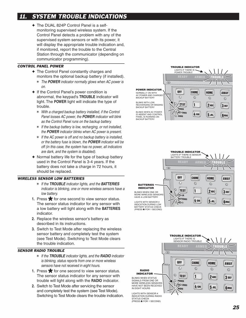
25
✦ The DUAL 824P Control Panel is a self-monitoring supervised wireless system. If the Control Panel detects a problem with any of the supervised system sensors or with its power, it will display the appropriate trouble indication and, if monitored, report the trouble to the Central Station through the communicator (depending on communicator programming).
CONTROL PANEL POWER✦ The Control Panel constantly charges and
monitors the optional backup battery (if installed).✴ The POWER indicator normally glows when AC power is
on.✦ If the Control Panel’s power condition is
abnormal, the keypad's TROUBLE indicator will light. The POWER light will indicate the type of trouble.✴ With a charged backup battery installed, if the Control
Panel looses AC power, the POWER indicator will blink as the Control Panel runs on the backup battery.
✴ If the backup battery is low, recharging, or not installed, the POWER indicator blinks when AC power is present.
✴ If the AC power is off and no backup battery is installed, or the battery fuse is blown, the POWER indicator will be off (in this case, the system has no power, all indicators are dark, and the system is disabled).
✦ Normal battery life for the type of backup battery used in the Control Panel is 3-4 years. If the battery does not take a charge in 72 hours, it should be replaced.
WIRELESS SENSOR LOW BATTERIES✴ If the TROUBLE indicator lights, and the BATTERIES
indicator is blinking, one or more wireless sensors have a low battery.
1. Press for one second to view sensor status. The sensor status indicator for any sensor with a low battery will light along with the BATTERIES indicator.
2. Replace the wireless sensor's battery as described in its instructions.
3. Switch to Test Mode after replacing the wireless sensor battery and completely test the system (see Test Mode). Switching to Test Mode clears the trouble indication.
SENSOR RADIO TROUBLE✴ If the TROUBLE indicator lights, and the RADIO indicator
is blinking, status reports from one or more wireless sensors have not received in eight hours.
1. Press for one second to view sensor status. The sensor status indicator for any sensor with trouble will light along with the RADIO indicator.
2. Switch to Test Mode after servicing the sensor and completely test the system (see Test Mode). Switching to Test Mode clears the trouble indication.
11. SYSTEM TROUBLE INDICATIONS
POWER INDICATORNORMALLY ON WITHAC POWER AND CHARGEDBACKUP BATTERY
BLINKS WITH LOW,RECHARGING OR MISSINGBACKUP BATTERY
BLINKS WHEN AC POWERIS ABSENT AND CONTROLPANEL IS RUNNING ONBACKUP BATTERY
TROUBLE INDICATORLIGHTS IF THERE ISPOWER TROUBLE
BATTERIESINDICATOR
TROUBLE INDICATORLIGHTS IF THERE IS SENSORBATTERY TROUBLE
BLINKS WHEN ONE ORMORE WIRELESS SENSORSHAVE A LOW BATTERY
LIGHTS WITH SENSOR #INDICATION DURING LOWBATTERY STATUS CHECK(PRESS FOR 1 SECOND)
RADIOINDICATOR
TROUBLE INDICATORLIGHTS IF THERE ISSENSOR RADIO TROUBLE
BLINKS WHEN STATUSSIGNALS FROM ONE ORMORE WIRELESS SENSORSHAVE NOT BEEN RECEIVEDIN EIGHT HOURS
LIGHTS WITH SENSOR #INDICATION DURING RADIOSTATUS CHECK(PRESS FOR 1 SECOND)

26
✦ Adding additional sensors will increase the protection provided by the system.
✦ All ground-level perimeter openings and accessible upper-story openings need protection.
✦ Motion detectors can protect interior areas and areas where valuables are kept.
ADDING SENSORS TO THE SYSTEM1. Always start with the system in Test Mode (enter
a user code and press TEST).2. Enter the master user code then press TEST.
✴ A “Gong” and fi ve “Beeps” will sound.✴ The sensor status indicators will light for each sensor
programmed into the Control Panel.3. Enter an unused sensor number from 01-24 (you
must enter two digits, example: 5 = 05).✎ NOTE: A sensor can be programmed into more
than one location. Be sure to choose an UNUSED sensor number. If a sensor gets entered into more than one location, delete the duplicates using the remove sensor function.
✴ The sensor status indicator light will fl ash for the sensor number selected.
4. Activate the sensor. (To add a wireless keypad, press the keypad's key.)✴ A “Bing” tone will sound when the sensor is programmed
into the Control Panel and the sensor status indicator will stay lit.
✴ A “Buzz” tone will sound if there is already another sensor programmed to that sensor number.
5. Enter another sensor number, or exit Setup Mode by pressing the key then press OFF for three seconds.
REMOVING SENSORS FROM THE SYSTEM✦ If a previously programmed sensor isn't going
to be used with the system anymore, or it's a duplicate that has been entered into more than one sensor location, it should be removed from the Control Panel's memory.
1. Start with the system in Test Mode.2. Enter the master user code then press TEST.
✴ A “Gong” and fi ve “Beeps” will sound.✴ The sensor status indicators will light for each sensor
programmed into the Control Panel.3. Enter the sensor number (from 01-24) that
you want to remove (you must enter two digits, example: 5 = 05).✴ The sensor status indicator light will fl ash for the sensor
number selected.4. Press TEST.
✴ A “Bing” tone will sound when the sensor has been removed and the sensor status indicator will turn off.
5. Enter another sensor number, or exit Setup Mode by pressing the key then press OFF for three seconds.
12. CUSTOMIZING THE SYSTEMSTART IN TEST
MASTERUSERCODE
1 GONG & 5 BEEPS(SETUP MODE)
NEW SENSORNUMBER
1 BING ANDSENSORINDICATORLIGHTS
REPEAT OR EXIT
ACTIVATESENSOR
SENSORINDICATORFLASHES
START IN TEST
MASTERUSERCODE
1 GONG & 5 BEEPS(SETUP MODE)
NUMBER OFSENSOR TOREMOVE
REPEAT OR EXIT
SENSORINDICATORFLASHES
REMOVESSENSOR
1 BING & SENSORINDICATORDARK

27
MAKING A SENSOR A 24-HOUR DOOR CHIME✦ Sensors can be programmed to cause the
keypad(s) to chime any time they're activated.✦ Chime-only sensors will not be able to trigger the
alarm in any system mode.✦ The sensor must have already been programmed
into the Control Panel (see “Adding Sensors to the System” for details).
1. Start with the system in Test Mode.2. Enter the master user code then press TEST.
✴ A “Gong” and fi ve “Beeps” will sound.✴ The sensor status indicators will light for each sensor
programmed into the Control Panel.3. Enter the sensor number from 01-24 (you must
enter two digits, example: 5 = 05).✴ The sensor status indicator light will fl ash for the sensor
number selected.4. Press HOME, 8, then AWAY.
✴ A “Bing” tone will sound and the sensor status indicator will light steady.
5. Enter another sensor number, or exit Setup Mode by pressing the key then press OFF for three seconds.
MAKING A SENSOR INTERIOR✦ Wireless motion detectors are automatically
programmed as interior sensors. Any other sensor can also be programmed as an interior sensor.
✦ Interior sensors can only trigger an alarm when the system is in the Away Mode.
✦ “Home Interior” sensors can trigger an alarm when the Control Panel is in the Home or Away mode.
✦ The sensor must have already been programmed into the Control Panel (see “Adding Sensors to the System” for details).
1. Start with the system in Test Mode.2. Enter the master user code then press TEST.
✴ A “Gong” and fi ve “Beeps” will sound.✴ The sensor status indicators will light for each sensor
programmed into the Control Panel.3. Enter the sensor number from 01-24 (you must
enter two digits, example: 5 = 05).✴ The sensor status indicator light will fl ash for the sensor
number selected.4. Press HOME, 7, then AWAY.
✴ A “Bing” tone will sound and the sensor status indicator will light steady.
5. Enter another sensor number, or exit Setup Mode by pressing the key then press OFF for three seconds.
START IN TEST
MASTERUSERCODE
1 GONG & 5 BEEPS(SETUP MODE)
NUMBER OFSENSORTO CHANGE
SENSORINDICATORFLASHES
ENTERS SENSORNUMBER
8 TO SELECT CHIMESENSOR FUNCTION
STORES CHANGE
1 BING AND SENSORINDICATOR LIT
START IN TEST
MASTERUSERCODE
1 GONG & 5 BEEPS(SETUP MODE)
NUMBER OFSENSORTO CHANGE
SENSORINDICATORFLASHES
ENTERS SENSORNUMBER
7 TO SELECTINTERIOR SENSORFUNCTION
STORES CHANGE
1 BING AND SENSORINDICATOR LIT
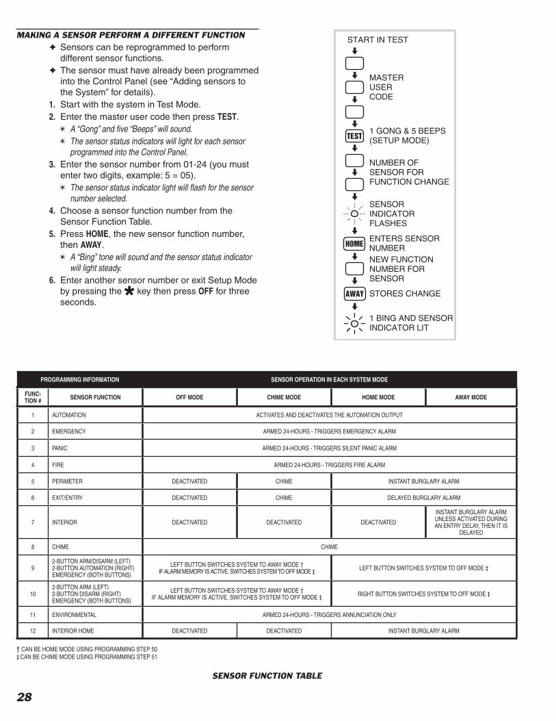
28
MAKING A SENSOR PERFORM A DIFFERENT FUNCTION✦ Sensors can be reprogrammed to perform
different sensor functions.✦ The sensor must have already been programmed
into the Control Panel (see “Adding sensors to the System” for details).
1. Start with the system in Test Mode.2. Enter the master user code then press TEST.
✴ A “Gong” and fi ve “Beeps” will sound.✴ The sensor status indicators will light for each sensor
programmed into the Control Panel.3. Enter the sensor number from 01-24 (you must
enter two digits, example: 5 = 05).✴ The sensor status indicator light will fl ash for the sensor
number selected.4. Choose a sensor function number from the
Sensor Function Table.5. Press HOME, the new sensor function number,
then AWAY.✴ A “Bing” tone will sound and the sensor status indicator
will light steady.6. Enter another sensor number or exit Setup Mode
by pressing the key then press OFF for three seconds.
PROGRAMMING INFORMATION SENSOR OPERATION IN EACH SYSTEM MODE
FUNC-TION # SENSOR FUNCTION OFF MODE CHIME MODE HOME MODE AWAY MODE
1 AUTOMATION ACTIVATES AND DEACTIVATES THE AUTOMATION OUTPUT
2 EMERGENCY ARMED 24-HOURS - TRIGGERS EMERGENCY ALARM
3 PANIC ARMED 24-HOURS - TRIGGERS SILENT PANIC ALARM
4 FIRE ARMED 24-HOURS - TRIGGERS FIRE ALARM
5 PERIMETER DEACTIVATED CHIME INSTANT BURGLARY ALARM
6 EXIT/ENTRY DEACTIVATED CHIME DELAYED BURGLARY ALARM
7 INTERIOR DEACTIVATED DEACTIVATED DEACTIVATED
INSTANT BURGLARY ALARM UNLESS ACTIVATED DURING AN ENTRY DELAY, THEN IT IS
DELAYED
8 CHIME CHIME
92-BUTTON ARM/DISARM (LEFT)2-BUTTON AUTOMATION (RIGHT)EMERGENCY (BOTH BUTTONS)
LEFT BUTTON SWITCHES SYSTEM TO AWAY MODE †IF ALARM MEMORY IS ACTIVE, SWITCHES SYSTEM TO OFF MODE ‡ LEFT BUTTON SWITCHES SYSTEM TO OFF MODE ‡
102-BUTTON ARM (LEFT)2-BUTTON DISARM (RIGHT)EMERGENCY (BOTH BUTTONS)
LEFT BUTTON SWITCHES SYSTEM TO AWAY MODE †IF ALARM MEMORY IS ACTIVE, SWITCHES SYSTEM TO OFF MODE ‡ RIGHT BUTTON SWITCHES SYSTEM TO OFF MODE ‡
11 ENVIRONMENTAL ARMED 24-HOURS - TRIGGERS ANNUNCIATION ONLY
12 INTERIOR HOME DEACTIVATED DEACTIVATED INSTANT BURGLARY ALARM
START IN TEST
MASTERUSERCODE
1 GONG & 5 BEEPS(SETUP MODE)
NUMBER OFSENSOR FORFUNCTION CHANGE
SENSORINDICATORFLASHES
ENTERS SENSORNUMBERNEW FUNCTIONNUMBER FORSENSOR
STORES CHANGE
1 BING AND SENSORINDICATOR LIT
SENSOR FUNCTION TABLE
† CAN BE HOME MODE USING PROGRAMMING STEP 50‡ CAN BE CHIME MODE USING PROGRAMMING STEP 51

29
✦ To perform any of the advanced programming steps, the system must be in the Setup Mode.
✦ Each programming function is performed with similar keystrokes. After the system is in Setup Mode, enter the programming step or sensor number and press HOME, then enter the new value and press AWAY. For reference, follow the fi gures next to the programming steps.✴ If the new value is accepted, a “bing” will sound. If the
new value is not accepted, a “double buzz” will sound.
CONTROL PANEL PROGRAMMING OPTIONS
STEP # PROGRAMMING FUNCTIONS POSSIBLE VALUES FACTORY VALUE INSTALLATION VALUE
25 ENTRY DELAY 20-255 SECONDS 30
26 EXIT DELAY 20-255 SECONDS 60
30 BURGLARY SIREN TIME 1-30 MINUTES 5
31 EMERGENCY SIREN TIME 1-30 MINUTES 5
32 FIRE SIREN TIME 1-30 MINUTES 5
40 AUTOMATION OUTPUT TIME 0-2500 SECONDS (0 = TOGGLE ON/OFF) 0
50 REMOTE ARMING MODE 2 = HOME MODE; 3 = AWAY MODE 3
51 REMOTE DISARMING MODE 0 = OFF MODE; 1 = CHIME MODE 0
61 ENTRY DELAY BEEPS 0 = OFF; 1 = ON 1
62 EXIT DELAY BEEPS 0 = OFF; 1 = ON 1
63 SILENT BURGLARY ALARM 0 = AUDIBLE; 1 = SILENT 0
64 SILENT EMERGENCY ALARM 0 = AUDIBLE; 1 = SILENT 0
65 QUICK ARMING 0 = OFF; 1 = ON 1
66 AUTO RESTORE 0 = OFF; 1 = ON 1
67 AUTO BYPASS 0 = OFF; 1 = ON 0
68 AUTOMATION MODE DURING ALARM 0 = FLASH (ENABLED BY FUNCTION 72)1 = STEADY (ENABLED BY FUNCTION 72) 0
69 AUTOMATION BING TOME 0 = NO BINGS1 = BINGS 1
70 REMOTE ARM/DISARM CHIRP 0 = NO CHIRPS1 = CHIRPS (1 CHIRP = ARMED, 2 CHIRPS = DISARMED) 1
71 AUTOMATION FLASHES AFTER ALARM 0 = STANDARD1 = FLASHING AFTER ALARM 0
72 AUTOMATION ACTIVE DURING ALARM0 = STANDARD1 = AUTOMATION ACTIVE DURING ALARM(FLASH OR STEADY PROGRAMMED BY FUNCTION 68)
0
73 AUTOMATION ON WHILE ARMED 0 = STANDARD1 = ON WHILE ARMED 0
74 AUTOMATION ON DURING EXIT/ENTRY 0 = STANDARD1 = ON DURING EXIT/ENTRY DELAY 0
75 AUTOMATION POLARITY 0 = + WHEN OFF; 1 = + WHEN ON 1
87 REMOTE ACCESS PASSWORD 6 DIGITS 987654
92 DURESS CODE 1-5 DIGITS REMOVED
93 RESTRICTED USER CODE #1 1-5 DIGITS REMOVED
94 RESTRICTED USER CODE #2 1-5 DIGITS REMOVED
95 RESTRICTED USER CODE #3 1-5 DIGITS REMOVED
96 RESTRICTED USER CODE #4 1-5 DIGITS REMOVED
97 RESTRICTED USER CODE #5 1-5 DIGITS REMOVED
98 PAGE ALERT USER CODE 1-5 DIGITS REMOVED
99 MASTER USER CODE 1-5 DIGITS 1234
SETUP MODE1. Start with the system in Test Mode (Setup Mode
cannot be reached from any other mode).2. From Test Mode, enter the master user code then
press TEST.✎ NOTE: Only the master user code can be used to
put the system into the Setup Mode. The restricted user codes cannot access Setup Mode, only Code Mode.
✴ A “Gong” and fi ve “Beeps” will sound, signaling that the system is in Setup Mode.
3. After programming changes are complete, press the OFF key for three seconds to exit Setup Mode.
✎ NOTE: If the system is left unattended in Setup Mode, it will automatically switch back to Off Mode after three minutes.
13. ADVANCED PROGRAMMING
ENTERS PROGRAM STEP ORSENSOR NUMBER TO MODIFY
STORES NEW VALUE
Control Panel Programming Table

30
CHANGING A SENSORS SUPERVISION✦ When a wireless sensor is programmed, the
Control Panel automatically sets it to supervised or non-supervised. The hardwire loops are always supervised for end-of-line resistor termination.
✦ The Control Panel expects hourly status transmissions from any wireless sensor programmed as supervised.
✦ Any wireless sensor can be programmed as supervised or non-supervised using this process.
✎ NOTE: Don't program a wireless sensor that doesn't send status transmissions as supervised.
CHANGING A SENSORS RESTORE REQUIREMENTS✦ When a wireless sensor is programmed, the
Control Panel automatically recognizes it as manual or automatic restoring. The hardwired loops are always manual restoring.
✦ The Control Panel expects restoral signals from any wireless sensor programmed as manual restore.
✦ Any wireless sensor can be programmed as manual or automatic restore using this process.
✎ NOTE: Don't program a wireless sensor that doesn't send restoral transmissions as manual restore.
ENTRY DELAY TIME✦ The factory-set Entry Delay time is 30 seconds.
STEP #25 The Entry Delay time can be adjusted from 20 to 255 seconds using this step. Write the new Entry Delay time in the User's Guide.
✎ NOTE: Don't make the Entry Delay too short. The user may not have enough time to disarm the system before an alarm.
EXIT DELAY TIME✦ The factory-set Exit Delay time is 60 seconds.
STEP #26 The Exit Delay time can be adjusted from 20 to 255 seconds using this step. Write the new Exit Delay time in the User's Guide.
BURGLARY SIREN TIME✦ The factory-set burglary siren time is fi ve minutes
(UL installation maximum).STEP #30 The burglary siren time can be adjusted from one
to 30 minutes using this step.
EMERGENCY SIREN TIME✦ The factory-set emergency siren time is fi ve
minutes (UL installation maximum).STEP #31 The emergency siren time can be adjusted from
one to 30 minutes using this step.
NUMBER OFSENSORTO CHANGE
SENSOR INDICATORFLASHES
ENTERS SENSOR NUMBER
18 FOR MANUAL RESTORE19 FOR AUTO RESTORE
STORES CHANGE
1 BING AND SENSORINDICATOR LIT
NUMBER OFSENSORTO CHANGE
SENSOR INDICATORFLASHES
ENTERS SENSOR NUMBER
16 FOR NON-SUPERVISED17 FOR SUPERVISED
STORES CHANGE
1 BING AND SENSORINDICATOR LIT
PROGRAMMING STEP #25
ENTERS STEP NUMBER
TIME IN SECONDS 20 - 255
STORES VALUE - 1 BING
PROGRAMMING STEP #26
ENTERS STEP NUMBER
TIME IN SECONDS 20 - 255
STORES VALUE - 1 BING
PROGRAMMING STEP #30
ENTERS STEP NUMBER
TIME IN MINUTES 1 - 30
STORES VALUE - 1 BING
PROGRAMMING STEP #31
ENTERS STEP NUMBER
TIME IN MINUTES 1 - 30
STORES VALUE - 1 BING

31
FIRE SIREN TIME✦ The factory-set fi re siren time is fi ve minutes (UL
installation maximum).STEP #32 The fi re siren time can be adjusted from one to
30 minutes using this step.
AUTOMATION OUTPUT TIME✦ The factory setting causes the Automation
Output to toggle between on and off with each activation.
STEP #40 The Automation Output can be programmed to turn on, then automatically turn off after one to 2500 seconds (42 minutes), or toggle on & off, using this step.
REMOTE CONTROL & HARDWIRE ARMING LEVEL✦ The factory setting causes the portable remote
controls to arm to the Away Mode.STEP #50 The portable remote controls can be changed to
arm to the Home Mode using this step.✎ NOTE: Changing this setting will affect all the
portable remote controls used with the system and all hardwired loops programmed as arm/disarm (sensor Function #9) key stations.
REMOTE CONTROL & HARDWIRE DISARMING LEVEL✦ The factory setting causes the portable remote
controls to disarm to the Off Mode.STEP #51 The remote controls can be changed to disarm to
the Chime Mode using this step.✎ NOTE: Changing this setting will affect all the
portable remote controls used with the system and all hardwired loops programmed as arm/disarm (sensor Function #9) key stations.
ENTRY DELAY BEEPS✦ The factory setting causes the keypad(s) to beep
during Entry Delays.STEP #61 The Entry Delay beeps can be silenced using
this step.✦ With the Entry Delay beeps off, the keypad(s) will
be silent after a delayed sensor is triggered until the Entry Delay expires, then the alarm siren will sound.
EXIT DELAY BEEPS✦ The factory setting causes the keypad(s) to beep
during Exit Delays.STEP #62 The Exit Delay beeps can be silenced using this
step.✦ With the Exit Delay beeps off, the keypad(s) will
be silent after arming to the Away Mode until the Exit Delay expires, then a single “Gong” tone will sound.
PROGRAMMING STEP #32
ENTERS STEP NUMBER
TIME IN MINUTES 1 - 30
STORES VALUE - 1 BING
PROGRAMMING STEP #40
ENTERS STEP NUMBER
TIME IN SECONDS 1 - 25000 = TOGGLE ON & OFF
STORES VALUE - 1 BING
PROGRAMMING STEP #50
ENTERS STEP NUMBER
2 FOR HOME MODE3 FOR AWAY MODE
STORES VALUE - 1 BING
PROGRAMMING STEP #51
ENTERS STEP NUMBER
0 FOR OFF MODE1 FOR CHIME MODE
STORES VALUE - 1 BING
PROGRAMMING STEP #61
ENTERS STEP NUMBER
0 FOR ENTRY BEEPS OFF1 FOR ENTRY BEEPS ON
STORES VALUE - 1 BING
PROGRAMMING STEP #62
ENTERS STEP NUMBER
0 FOR EXIT BEEPS OFF1 FOR EXIT BEEPS ON
STORES VALUE - 1 BING

32
SILENT BURGLARY ALARMS✦ The factory setting causes audible burglary
alarms.STEP #63 The Control Panel can be programmed for silent
burglary alarms using this step.
SILENT EMERGENCY ALARMS✦ The factory setting causes audible emergency
alarms.STEP #64 The Control Panel can be programmed for silent
emergency alarms using this step.
DISABLING QUICK ARMING✦ The factory setting allows quick arming of the
Control Panel by pressing down the mode keys for two seconds.
STEP #65 The Control Panel can be programmed to not allow quick arming using this step. If quick arming is disabled, a user code must be entered before pressing the mode buttons.
✎ NOTE: For commercial installations with retail traffi c, it is recommended to disable quick arming to prevent customers from arming the system.
✎ NOTE: If quick arming is disabled the Home Instant Mode is unavailable.
AUTOMATIC RESTORAL OF BYPASSED SENSORS✦ Bypassed sensors are ignored by the Control
Panel and cannot cause an alarm.✦ The factory setting causes the Control Panel to
automatically restore (remove the bypass from) sensors that close. After it's restored, the sensor is ready to cause an alarm the next time it is opened.
STEP #66 The Control Panel can be programmed to not automatically restore any bypassed sensor when the sensor closes using this step. Bypassed sensors will then remain bypassed until the system is disarmed.
✎ NOTE: This setting affects all sensors.
AUTOMATIC BYPASSING OF OPEN SENSORS✦ The factory setting requires the user to manually
bypass any open sensors when the system is armed.✴ If arming is attempted with open sensors, the keypad(s)
will sound fi ve two-tone Beeps and will not arm.✦ Arming to the same mode again within fi ve
seconds will bypass any open sensors and arm the Control Panel.
STEP #67 The Control Panel can be programmed to automatically bypass any open sensors when the system is armed using this step.
✎ NOTE: This setting affects all sensors.
PROGRAMMING STEP #63
PROGRAM
0 FOR AUDIBLE BURGLARY1 FOR SILENT BURGLARY
STORE - 1 BING
PROGRAMMING STEP #64
ENTERS STEP NUMBER
0 FOR AUDIBLE EMERGENCY1 FOR SILENT EMERGENCY
STORES VALUE - 1 BING
PROGRAMMING STEP #66
ENTERS STEP NUMBER
0 FOR AUTO RESTORAL OFF1 FOR AUTO RESTORAL ON
STORES VALUE - 1 BING
PROGRAMMING STEP #65
ENTERS STEP NUMBER
0 FOR QUICK ARMING OFF1 FOR QUICK ARMING ON
STORES VALUE - 1 BING
PROGRAMMING STEP #67
ENTERS STEP NUMBER
0 FOR AUTO BYPASS OFF1 FOR AUTO BYPASS ON
STORES VALUE - 1 BING

33
AUTOMATION OUTPUT MODE DURING ALARM✦ The factory setting causes the Automation
Output to fl ash if it is programmed to activate during or after an alarm.
✎ NOTE: For the Automation Output to activate during or after an alarm, that function must be enabled with Programming Step 71 or 72.
STEP #68 The output can be programmed to be a steady output using this step.
AUTOMATION ACTIVATION TONE✦ The factory setting causes the keypad(s) to
sound a “Bing” when the Automation Output is activated by pressing the key, or when it's triggered with a two-button remote control.
STEP #69 This sound can be silenced using this step.
REMOTE CONTROL & HARDWIRE ARM/DISARM CHIRP✦ When arming with the portable remote control
or with a hardwired loop programmed as arm/disarm (sensor Function #9), the factory setting causes the keypad(s) to “chirp” once when armed, twice when disarmed, and three times when arming with sensors bypassed.
STEP #70 These chirps can be silenced using this step.✎ NOTE: If these chirps are silenced, it is
recommended to program the Automation Output to be active when the system is armed, so a light can be triggered displaying the arming status of the system.
AUTOMATION OUTPUT ON DURING AND AFTER ALARM✦ The factory setting causes the Control Panel's
Automation Output to activate when pressing the key, or when it's triggered with a two-button
remote control.STEP #71 The Control Panel can be programmed to
activate the Automation Output during and after any alarms as well as when normally triggered using this step.
✎ NOTE: The output will continue until the fl ashing sensor status lights are cleared.
AUTOMATION OUTPUT ON DURING ALARM✦ The factory setting causes the Control Panel's
Automation Output to activate when pressing the key, or when it's triggered with a two-button
remote control.STEP #72 The Control Panel can be programmed to
activate the Automation Output during alarms as well as when normally triggered using this step.
✎ NOTE: The Automation Output can be programmed to fl ash or be steady during alarm, see Programming Step 68.
PROGRAMMING STEP #68
ENTERS STEP NUMBER
0 FOR FLASHING OUTPUT1 FOR STEADY OUTPUT
STORES VALUE - 1 BING
PROGRAMMING STEP #69
ENTERS STEP NUMBER
0 FOR BING TONE OFF1 FOR BING TONE ON
STORES VALUE - 1 BING
PROGRAMMING STEP #70
ENTERS STEP NUMBER
0 FOR CHIRPS OFF1 FOR CHIRPS ON
STORES VALUE - 1 BING
PROGRAMMING STEP #71
ENTERS STEP NUMBER
0 FOR STANDARD TRIGGER1 FOR OUTPUT DURING & AFTER ALARM
STORES VALUE - 1 BING
PROGRAMMING STEP #72
ENTERS STEP NUMBER
0 FOR STANDARD TRIGGER1 FOR OUTPUT DURING ALARM
STORES VALUE - 1 BING
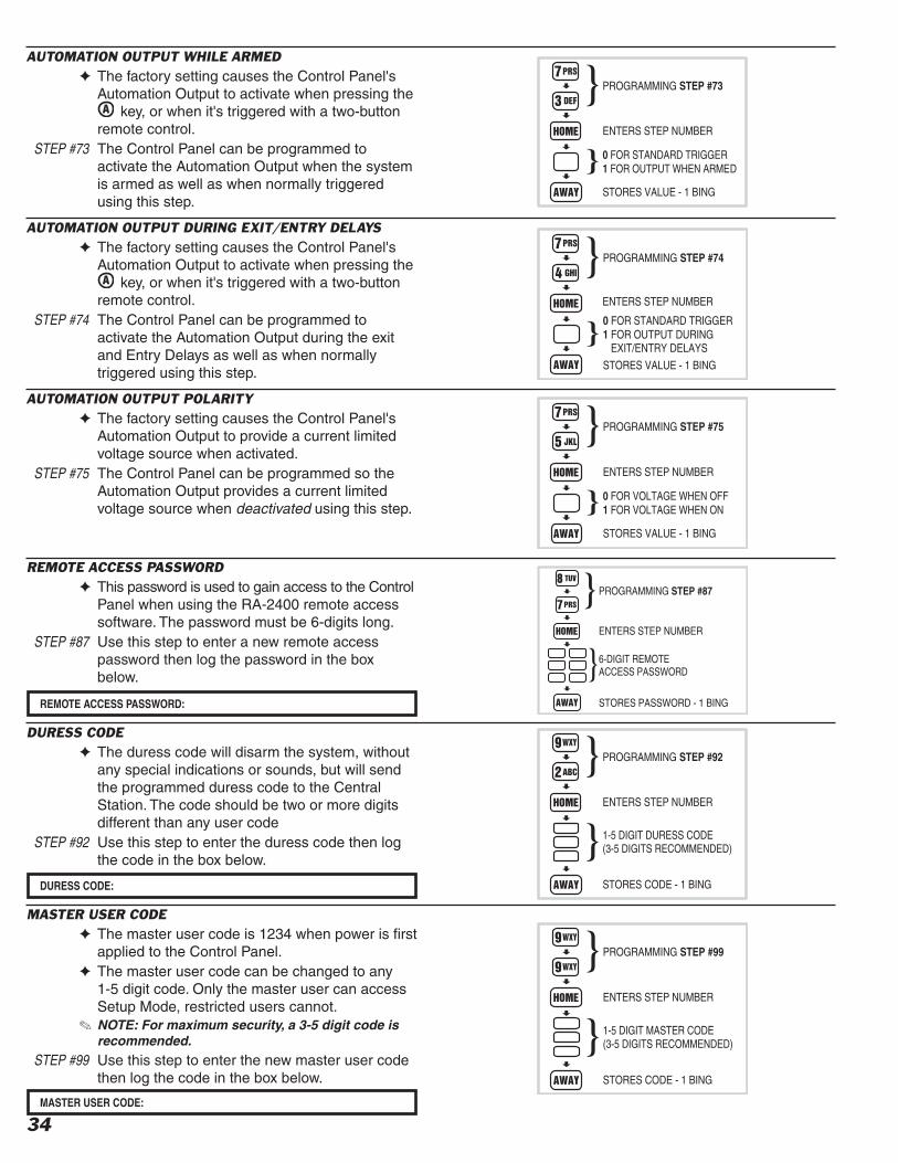
34
AUTOMATION OUTPUT WHILE ARMED✦ The factory setting causes the Control Panel's
Automation Output to activate when pressing the key, or when it's triggered with a two-button
remote control.STEP #73 The Control Panel can be programmed to
activate the Automation Output when the system is armed as well as when normally triggered using this step.
AUTOMATION OUTPUT DURING EXIT/ENTRY DELAYS✦ The factory setting causes the Control Panel's
Automation Output to activate when pressing the key, or when it's triggered with a two-button
remote control.STEP #74 The Control Panel can be programmed to
activate the Automation Output during the exit and Entry Delays as well as when normally triggered using this step.
AUTOMATION OUTPUT POLARITY✦ The factory setting causes the Control Panel's
Automation Output to provide a current limited voltage source when activated.
STEP #75 The Control Panel can be programmed so the Automation Output provides a current limited voltage source when deactivated using this step.
REMOTE ACCESS PASSWORD✦ This password is used to gain access to the Control
Panel when using the RA-2400 remote access software. The password must be 6-digits long.
STEP #87 Use this step to enter a new remote access password then log the password in the box below.
DURESS CODE✦ The duress code will disarm the system, without
any special indications or sounds, but will send the programmed duress code to the Central Station. The code should be two or more digits different than any user code
STEP #92 Use this step to enter the duress code then log the code in the box below.
MASTER USER CODE✦ The master user code is 1234 when power is fi rst
applied to the Control Panel.✦ The master user code can be changed to any
1-5 digit code. Only the master user can access Setup Mode, restricted users cannot.
✎ NOTE: For maximum security, a 3-5 digit code is recommended.
STEP #99 Use this step to enter the new master user code then log the code in the box below.
PROGRAMMING STEP #73
ENTERS STEP NUMBER
0 FOR STANDARD TRIGGER1 FOR OUTPUT WHEN ARMED
STORES VALUE - 1 BING
PROGRAMMING STEP #74
ENTERS STEP NUMBER
0 FOR STANDARD TRIGGER1 FOR OUTPUT DURING EXIT/ENTRY DELAYS
STORES VALUE - 1 BING
PROGRAMMING STEP #75
ENTERS STEP NUMBER
0 FOR VOLTAGE WHEN OFF1 FOR VOLTAGE WHEN ON
STORES VALUE - 1 BING
PROGRAMMING STEP #87
ENTERS STEP NUMBER
6-DIGIT REMOTEACCESS PASSWORD
STORES PASSWORD - 1 BINGREMOTE ACCESS PASSWORD:
PROGRAMMING STEP #92
ENTERS STEP NUMBER
1-5 DIGIT DURESS CODE(3-5 DIGITS RECOMMENDED)
STORES CODE - 1 BINGDURESS CODE:
MASTER USER CODE:
PROGRAMMING STEP #99
ENTERS STEP NUMBER
1-5 DIGIT MASTER CODE(3-5 DIGITS RECOMMENDED)
STORES CODE - 1 BING
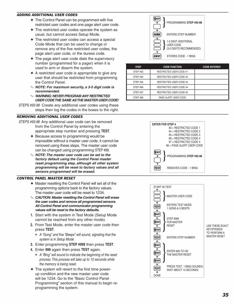
35
ADDING ADDITIONAL USER CODES✦ The Control Panel can be programmed with fi ve
restricted user codes and one page alert user code.✦ The restricted user codes operate the system as
usual, but cannot access Setup Mode.✦ The restricted user codes can access a special
Code Mode that can be used to change or remove any of the fi ve restricted user codes, the page alert user code, or the duress code.
✦ The page alert user code dials the supervisory number (programmed for a pager) when it is used to arm or disarm the system.
✦ A restricted user code is appropriate to give any user that should be restricted from programming the Control Panel.
✎ NOTE: For maximum security, a 3-5 digit code is recommended.
✎ WARNING: NEVER PROGRAM ANY RESTRICTED USER CODE THE SAME AS THE MASTER USER CODE!
STEPS #93-98 Create any additional user codes using these steps then log the codes in the boxes to the right.
REMOVING ADDITIONAL USER CODESSTEPS #93-98 Any additional user code can be removed
from the Control Panel by entering the appropriate step number and pressing TEST.
✦ Because access to programming would be impossible without a master user code, it cannot be removed using these steps. The master user code can be changed using programming STEP #99.
✎ NOTE: The master user code can be set to the factory default using the Control Panel master reset programming step, although all other system programming will be reset to factory values and all sensors programmed will be erased.
CONTROL PANEL MASTER RESET✦ Master resetting the Control Panel will set all of the
programming options back to the factory values. The master user code will be reset to 1234.
✎ CAUTION: Master resetting the Control Panel will erase the user codes and remove all programmed sensors. All Control Panel and communicator programming values will be reset to the factory defaults.
1. Start with the system in Test Mode (Setup Mode cannot be reached from any other mode).
2. From Test Mode, enter the master user code then press TEST.✴ A “Gong” and fi ve “Beeps” will sound, signaling that the
system is in Setup Mode.3. Enter programming STEP #999 then press TEST.4. Enter 999 again then press TEST again.
✴ A “Bing” will sound to indicate the beginning of the reset process. This process will take up to 10 seconds while the memory is being reset.
✦ The system will revert to the fi rst time power-up condition and the new master user code will be 1234. Go to the “Basic Control Panel Programming” section of this manual to begin re-programming the system.
PROGRAMMING STEP #93-98
ENTERS STEP NUMBER
1-5 DIGIT ADDITIONALUSER CODE(3-5 DIGITS RECOMMENDED)
STORES CODE - 1 BING
PROGRAMMING STEP #93-98
REMOVES CODE - 1 BING
93 = RESTRICTED CODE 194 = RESTRICTED CODE 295 = RESTRICTED CODE 396 = RESTRICTED CODE 497 = RESTRICTED CODE 5
98 = PAGE ALERT USER CODE
ENTER FOR STEP #
MASTER USER CODE
ENTERS TEST MODE1 GONG & 5 BEEPS
STEP #999FOR MASTERRESET
ENTER 999 TO OKTHE MASTER RESET
START IN TEST
DONE
USE THESE EXACTKEYSTROKESTO PERFORM AMASTER RESETENTERS STEP NUMBER
PRESS TEST, 1 BING SOUNDS,WAIT ABOUT 10 SECONDS
STEP CODE FUNCTION CODE ENTERED
STEP #93 RESTRICTED USER CODE #1
STEP #94 RESTRICTED USER CODE #2
STEP #95 RESTRICTED USER CODE #3
STEP #96 RESTRICTED USER CODE #4
STEP #97 RESTRICTED USER CODE #5
STEP #98 PAGE ALERT USER CODE

36
✦ To perform any of the advanced programming steps, the system must be in the Setup Mode.
✦ Each programming function is performed with similar keystrokes. After the system is in Setup Mode, enter the programming step number and press HOME, then enter the new value and press AWAY. For reference, follow the fi gures next to the programming steps.✴ If the new value is accepted, a “Bing” will sound. If the
new value is not accepted, a “Double Buzz” will sound.
SETUP MODE1. Start with the system in Test Mode (Setup Mode
cannot be reached from any other mode).2. From Test Mode, enter the master user code then
press TEST.✎ NOTE: Only the master user code can be used to
put the system into the Setup Mode. The restricted user codes cannot access Setup Mode, only Code Mode.
✴ A “Gong” and fi ve “Beeps” will sound, signaling that the system is in Setup Mode.
3. After programming changes are complete, press the OFF key for three seconds to exit Setup Mode.
✎ NOTE: If the system is left unattended in Setup Mode, it will automatically switch back to Off Mode after three minutes.
14. COMMUNICATOR PROGRAMMING
ENTERS PROGRAM STEPNUMBER TO MODIFY
STORES NEW VALUE
General Communicator Programming Table
START IN TEST
MASTERUSERCODE
1 GONG & 5 BEEPS(SETUP MODE)
GENERAL COMMUNICATOR OPTIONS
STEP # PROGRAMMINGFUNCTION
POSSIBLEVALUES
FACTORY VALUE
INSTALLATION VALUE
76 2-WAY AUDIO 0= NONE; 1 = LISTEN; 2 = 2-WAY MANUAL; 3 = 2-WAY FULL DUPLEX 0
78 VOICE RESPONSE FROM KEYPAD SPEAKER 0 = VOICE RESPONSE DISABLED1 = VOICE RESPONSE ENABLED 0
100 REMOTE PROGRAMMING LOCKOUT 0 = UNLOCK; 1 = LOCK 0
101 CALL LIMITER 0 = OFF; 1 = FIVE CALLS PER ARMING PERIOD 0
103 DIALING DELAY 0 = NO DELAY; 1 = 30 SECOND DELAY 0
104 DIALING METHOD 0 = TONE; 1 = PULSE 0
107 COMMUNICATOR ENABLE 0 = COMMUNICATOR OFF; 1 = COMMUNICATOR ON 0

37
GENERAL COMMUNICATOR OPTIONS
COMMUNICATOR ENABLE✦ The factory setting for the Control Panel disables
the communicator. If the system is going to be a non-monitored, local alarm only, leave the communicator disabled.
STEP #107 If the system is going to be monitored by a Central Station, enable the communicator with this programming step.
2-WAY AUDIO✦ When the Model VB-2 voice module is installed,
the communicator can provide 2-way audio capability.
✦ The audio module can be programmed for listen-only, 2-way manual operation (using a pushbutton telephone at the Central Station), and 2-way full duplex hands free operation.
✦ Refer to the VB-2 installation instructions for details on operating the audio module.
✎ NOTE: The Model VB-2 digital voice response module must be installed for this option to function.
✦ The factory setting for the VB-2 audio module is OFF.STEP #76 The audio module can be set for (1) listen-only, (2)
2-way manual, (3) 2-way full duplex using this step.✎ NOTE: For safety, 2-way audio will not activate if
the system is disarmed with the duress code.✎ NOTE:Units programmed for two-way duplex can
still be controlled manually by pressing the “1” or “3” key. In addition, the Central Station can return the unit to two-way duplex by pressing the “8” key.
VOICE RESPONSE✦ The Control Panel can be programmed to allow
the keypad(s) speaker to play audio produced by the VB-2 digital voice response module.
✦ This selection can also be used when a remote speaker is connected to the Control Panel.
✦ The factory setting is to disable the keypad(s) speaker from playing voice module audio.
STEP #78 The Control Panel can be programmed to enable voice module audio using this step.
✎ NOTE: Turning voice response OFF with this programming step will only effect the audio produced by the voice module. It will not stop the keypad(s) speaker from sounding local sirens and tones.
✎ NOTE: A Model VB-2 digital voice response module must be installed for this option to function.
REMOTE LOCKOUT✦ The factory setting for the communicator allows
remote connection to the Control Panel with Linear's RA-2400 Remote Access Software and a modem (unlocked).
STEP #100 The Control Panel can be programmed to not answer incoming calls, thereby, not allowing remote access (locked) using this step.
PROGRAMMING STEP #107
ENTERS STEP NUMBER
0 FOR COMMUNICATOR OFF1 FOR COMMUNICATOR ON
STORES VALUE - 1 BING
PROGRAMMING STEP #76
ENTERS STEP NUMBER0 FOR NO AUDIO MONITORING1 FOR LISTEN-ONLY2 FOR 2-WAY MANUAL3 FOR 2-WAY FULL DUPLEXSTORES VALUE - 1 BING
PROGRAMMING STEP #78
ENTERS STEP NUMBER
0 FOR NO VOICE RESPONSEE1 FOR VOICE RESPONSE
STORES VALUE - 1 BING
PROGRAMMING STEP #100
ENTERS STEP NUMBER
0 FOR UNLOCK1 FOR LOCK
STORES VALUE - 1 BING

38
CALL LIMITER✦ The factory setting for the call limiter is OFF.
This allows the communicator to report burglary alarms, once for each sensor, as many times as they are triggered.
STEP #101 The Control Panel can be programmed to only allow fi ve burglary reports total per arming period using this step.
✎ NOTE: Sensors programmed for 24-hour functions (Emergency, Panic, Fire) always send a Central Station report and always sound the local siren regardless of the Call Limiter setting.
DIALING DELAY✦ The factory setting will cause the communicator
to dial the Central Station instantly when an alarm or supervisory event occurs.
STEP #103 The communicator can be programmed to wait 30 seconds before dialing using this step. This gives the user time to disarm the system and prevent communications in the case of a subscriber generated false alarm.
DIALING METHOD✦ The factory setting causes the communicator to
dial using DTMF (dual-tone multi-frequency) tone dialing.
STEP #104 The communicator can be programmed to use pulse (rotary) dialing using this step. Use this option if the telephone line in the installation does not support tone dialing.
PROGRAMMING STEP #101
ENTERS STEP NUMBER
0 FOR OFF (UNLIMITED)1 FOR ON (5 VIOLATIONS)
STORES VALUE - 1 BING
PROGRAMMING STEP #103
ENTERS STEP NUMBER
0 FOR NO DELAY1 FOR 30 SECOND DELAY
STORES VALUE - 1 BING
PROGRAMMING STEP #104
ENTERS STEP NUMBER
0 FOR TONE DIALING1 FOR PULSE DIALING
STORES VALUE - 1 BING

39
COMMUNICATOR REPORTING OPTIONS
REPORTING FORMAT✦ The factory setting causes the communicator
to report using the 4 BY 2 FORMAT. This format allows four-digit account numbers from 0000 to 9999 and provides two-digit alarm codes.
STEP #105 ADEMCO CONTACT ID can be chosen as a reporting format using this step. This format allows 4-digit account numbers from 0000 to 9999 and provides verbose report descriptions with Ademco Contact ID compatible Central Stations.
CALL ROUTING✦ The communicator can be programmed with
three telephone numbers; primary, secondary, and supervisory.
✦ The factory setting for the communicator is to route all calls to the primary telephone number. If communication is unsuccessful after fi ve attempts to the primary number, the secondary number will be dialed for an additional fi ve attempts. If the secondary number cannot be reached, the communicator will “sleep” for fi ve minutes before starting the call process over again. A total of four sleep cycles (50 call attempts) can occur before the communicator stops calling.
STEP #86 The communicator can be programmed to report supervisory events (low battery, trouble, AC failure, etc.) to the supervisory telephone number instead of the primary or secondary telephone numbers using this step.
PROGRAMMING STEP #105
ENTERS STEP NUMBER
0 FOR 4 BY 21 FOR ADEMCO CONTACT ID
STORES VALUE - 1 BING
PROGRAMMING STEP #86
ENTERS STEP NUMBER
0 FOR ALL CALLS TO PRIMARY/SECONDARY1 FOR ALARMS ONLY TO PRIMARY/SECONDARY
STORES VALUE - 1 BING
Communicator Reporting Option Table
✎ CAUTION: If the page alert user code feature is going to be used, the supervisory number is reserved for the pager number. DO NOT SET THE CALL ROUTING OPTION TO “1”.
✎ NOTE: To disable supervisory reports, set call routing option to “1” and remove the supervisory telephone number.
✎ NOTE: Do not program the primary and secondary telephone numbers the same. See the FCC Telephone Rules and Regulations on the rear cover of this manual.
COMMUNICATOR REPORTING OPTIONS
STEP #
PROGRAMMING FUNCTION
POSSIBLEVALUES
FACTORY VALUE
INSTALLATIONVALUE
86 CALL ROUTING0 = ALL CALLS TO PRIMARY OR SECONDARY NUMBER1 = ALL ALARM CALLS TO PRIMARY OR SECONDARY NUMBER AND ALLOTHERS TO SUPERVISORY NUMBER
0
88 ACCOUNT NUMBER 4 DIGITS EMPTY
89 PRIMARY PHONE NUMBER UP TO 20 DIGITS EMPTY
90 SECONDARY PHONE NUMBER UP TO 20 DIGITS EMPTY
91 SUPERVISORY/PAGER PHONE NUMBER UP TO 20 DIGITS EMPTY
PRESSING THE (A) KEY INSERTS A 1-SECOND DELAY THE [FIRE] KEY INSERTS A 5-SECOND DELAYFOR ALL PHONE NUMBERS ⇒ ⇒ ⇒ THE [CHIME] KEY INSERTS A “*” THE (A) KEY INSERTS A “#” IF IT IS THE LAST DIGIT OF THE PHONE NUMBER
105 REPORTING FORMAT 0 = 4 BY 2; 1 = ADEMCO 0
108 REPORT SYSTEM TROUBLE 0 = NO; 1 = YES 0
110 REPORT FORCE ARMING 0 = NO; 1 = YES 0
111 OPEN/CLOSE 0 = NO; 1 = YES; 2 = MASTER PAC ONLY 0
113 POINT ID REPORTING FOR 4 BY 2 FORMAT 0 = NO; 1 = YES 1

40
ACCOUNT NUMBER✦ The account number entered for the
communicator must be 4-digits long.✦ The factory setting for the account number is
0000.STEP #88 Enter an account number from 0000 to 9999
using this step.
PRIMARY TELEPHONE NUMBER✦ The primary Central Station telephone number
can be up to 20-digits long.✦ Digits 0-9 can be used.✦ Delays and special characters can be entered in
the telephone number (see below).STEP #89 Enter the primary telephone number using this
step.
SECONDARY TELEPHONE NUMBER✦ The secondary Central Station telephone
number can be up to 20-digits long.✦ Digits 0-9 can be used.✦ Delays and special characters can be entered in
the telephone number (see below).STEP #90 Enter the secondary telephone number using this
step.✎ NOTE: To remove the secondary telephone
number, enter step number 90 then press TEST.
SUPERVISORY OR PAGER TELEPHONE NUMBER✦ The supervisory Central Station or pager
telephone number can be up to 20-digits long.✦ Digits 0-9 can be used.✦ Delays and special characters can be entered
in the telephone number (see below). If this is a pager number, enter enough delays for the phone to answer. Then, enter the number to be dialed.
✦ End a pager number with the completion character (usually a pound (#) character).
STEP #91 Enter the supervisory or pager telephone number using this step.
✎ NOTE: To remove the supervisory/pager telephone number, enter step number 91 then press TEST.
TELEPHONE NUMBER DELAYS AND SPECIAL CHARACTERS✦ When creating telephone numbers with
programming Steps 89, 90, & 91, use the following keys to add dialing delays or special characters.
✦ Press the key to place a 1-second dialing delay at the start or anywhere in the middle of the telephone number.
✦ Pressing the key as the last digit of the telephone number will place a pound character at the end of the telephone number.
✦ Press the FIRE key to place a 5-second dialing delay anywhere in the telephone number.
✦ Press the CHIME key to place a star character anywhere in the telephone number.
PROGRAMMING STEP #88
ENTERS STEP NUMBER
4-DIGIT ACCOUNT NUMBER
STORES VALUE - 1 BING
PROGRAMMING STEP #89
ENTERS STEP NUMBER
UP TO 20 DIGITS FOR THEPRIMARY NUMBER
STORES VALUE - 1 BING
PROGRAMMING STEP #90
ENTERS STEP NUMBER
UP TO 20 DIGITS FOR THESECONDARY NUMBER
STORES VALUE - 1 BING
PROGRAMMING STEP #91
ENTERS STEP NUMBER
UP TO 20 DIGITS FOR THESUPERVISORY/PAGERNUMBER
STORES VALUE - 1 BING
ADDS A 1-SECOND DELAY(START OR MIDDLE OF NUMBER)
ADDS A POUND (#) CHARACTER(END OF NUMBER)
ADDS A 5-SECOND DELAY(ANYWHERE IN NUMBER)
ADDS A STAR ( ) CHARACTER(ANYWHERE IN NUMBER)

41
REPORT CONTROL PANEL TROUBLE✦ The factory setting does not report Control Panel
trouble events to the Central Station.STEP #108 The communicator can be programmed to
report Control Panel trouble events using this step. These include all conditions that light the keypad(s) BATTERIES or TROUBLE indicator. It also includes low Control Panel backup battery.
REPORT FORCE ARMING✦ The factory setting does not send force arming
reports.STEP #110 The communicator can be programmed to report
force arming anytime the Control Panel is armed with one or more bypassed sensors using this step.
✦ The factory set reporting code for force arming is “65” (Code 574 with Ademco).
✎ NOTE: If force arming is enabled, and the Control Panel is force armed (armed with an open sensor) remotely by telephone, or with the RA-2400 Remote Access software, the caller will be disconnected if the communicator is enabled.
OPENING AND CLOSING REPORTS✦ The factory setting does not send opening and
closing reports.STEP #111 The communicator can be programmed to send
an opening report when the system is disarmed, and a closing report when the system is armed for all users, or just the master user using this step.
✎ NOTE 1: For commercial installations with retail traffi c using opening and closing reports, it is recommended to disable quick arming to prevent customers from arming the system.
✎ NOTE 2: The reporting codes are fi xed for opening and closing. A unique code is reserved for the master user code and each of the fi ve restricted user codes.
✎ NOTE 3: Arming or disarming with the page alert user code dials the supervisory number, no opening or closing report is sent.
POINT ID REPORTING✦ The factory setting enables Point ID and allows
the communicator to send two-digit alarm and trouble codes for each sensor. The individual sensor that causes an alarm or trouble report can be identifi ed at the Central Station.
STEP #113 Point ID can be disabled using this step. The Central Station will only receive general alarm and trouble reports.
PROGRAMMING STEP #108
ENTERS STEP NUMBER
0 FOR NO CONSOLE TROUBLE1 FOR CONSOLE TROUBLE
STORES VALUE - 1 BING
PROGRAMMING STEP #110
ENTERS STEP NUMBER
0 FOR NO FORCE ARMING RPTS.1 FOR FORCE ARMING RPTS.
STORES VALUE - 1 BING
PROGRAMMING STEP #111
ENTERS STEP NUMBER
0 FOR NO OPEN/CLOSE REPORTS1 FOR O/C RPTS. FOR ALL USERS2 FOR O/C RPTS. FROM MASTER USER ONLY
STORES VALUE - 1 BING
PROGRAMMING STEP #113
ENTERS STEP NUMBER
0 FOR GENERAL REPORTS ONLY1 FOR POINT ID REPORTING
STORES VALUE - 1 BING
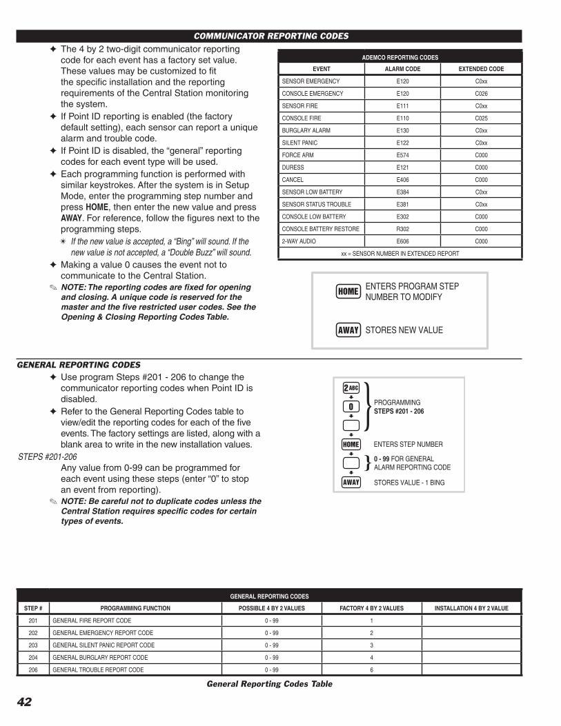
42
COMMUNICATOR REPORTING CODES✦ The 4 by 2 two-digit communicator reporting
code for each event has a factory set value. These values may be customized to fi t the specifi c installation and the reporting requirements of the Central Station monitoring the system.
✦ If Point ID reporting is enabled (the factory default setting), each sensor can report a unique alarm and trouble code.
✦ If Point ID is disabled, the “general” reporting codes for each event type will be used.
✦ Each programming function is performed with similar keystrokes. After the system is in Setup Mode, enter the programming step number and press HOME, then enter the new value and press AWAY. For reference, follow the fi gures next to the programming steps.✴ If the new value is accepted, a “Bing” will sound. If the
new value is not accepted, a “Double Buzz” will sound.✦ Making a value 0 causes the event not to
communicate to the Central Station.✎ NOTE: The reporting codes are fi xed for opening
and closing. A unique code is reserved for the master and the fi ve restricted user codes. See the Opening & Closing Reporting Codes Table.
GENERAL REPORTING CODES✦ Use program Steps #201 - 206 to change the
communicator reporting codes when Point ID is disabled.
✦ Refer to the General Reporting Codes table to view/edit the reporting codes for each of the fi ve events. The factory settings are listed, along with a blank area to write in the new installation values.
STEPS #201-206Any value from 0-99 can be programmed for each event using these steps (enter “0” to stop an event from reporting).
✎ NOTE: Be careful not to duplicate codes unless the Central Station requires specifi c codes for certain types of events.
ENTERS PROGRAM STEPNUMBER TO MODIFY
STORES NEW VALUE
PROGRAMMINGSTEPS #201 - 206
ENTERS STEP NUMBER
0 - 99 FOR GENERALALARM REPORTING CODE
STORES VALUE - 1 BING
General Reporting Codes Table
GENERAL REPORTING CODES
STEP # PROGRAMMING FUNCTION POSSIBLE 4 BY 2 VALUES FACTORY 4 BY 2 VALUES INSTALLATION 4 BY 2 VALUE
201 GENERAL FIRE REPORT CODE 0 - 99 1
202 GENERAL EMERGENCY REPORT CODE 0 - 99 2
203 GENERAL SILENT PANIC REPORT CODE 0 - 99 3
204 GENERAL BURGLARY REPORT CODE 0 - 99 4
206 GENERAL TROUBLE REPORT CODE 0 - 99 6
ADEMCO REPORTING CODES
EVENT ALARM CODE EXTENDED CODE
SENSOR EMERGENCY E120 C0xx
CONSOLE EMERGENCY E120 C026
SENSOR FIRE E111 C0xx
CONSOLE FIRE E110 C025
BURGLARY ALARM E130 C0xx
SILENT PANIC E122 C0xx
FORCE ARM E574 C000
DURESS E121 C000
CANCEL E406 C000
SENSOR LOW BATTERY E384 C0xx
SENSOR STATUS TROUBLE E381 C0xx
CONSOLE LOW BATTERY E302 C000
CONSOLE BATTERY RESTORE R302 C000
2-WAY AUDIO E606 C000
xx = SENSOR NUMBER IN EXTENDED REPORT

43
SYSTEM REPORTING CODES✦ Refer to the System Reporting Codes table to
view/edit the reporting codes for the keypad FIRE and EMERGENCY buttons and for each of the three Control Panel conditions. The factory settings are listed, along with a blank area to write in the new installation values.
STEPS #261-266Any value from 0-99 can be programmed for each event using these steps (enter “0” to stop an event from reporting).
FORCE ARMING REPORTING CODE✦ The factory set reporting code for force arming is
“65” (Code 574 with Ademco).STEP #258 Any value from 0-99 can be programmed for this
event using this step (0 = no report).✎ NOTE: For force arming reporting, force arming
reports must be enabled. See Page 41.
DURESS REPORTING CODE✦ The factory set reporting code for Duress is “66”
(Code 121 with Ademco).STEP #259 Any value from 0-99 can be programmed for this
event using this step (0 = no report).✎ NOTE: For duress code reporting a keypad duress
code must be programmed. See Page 34.
SYSTEM REPORTING CODES
STEP # PROGRAMMING FUNCTION POSSIBLE 4 BY 2 VALUES
FACTORY 4 BY 2 VALUES ADEMCO VALUE INSTALLATION
4 BY 2 VALUE
258 FORCE ARMING REPORT CODE 0 - 99 65 574
259 DURESS REPORT CODE 0 - 99 66 121
261 SYSTEM FIRE REPORT CODE 0 - 99 68 110
262 SYSTEM EMERGENCY REPORT CODE 0 - 99 69 120
263 SYSTEM TEST/CANCEL REPORT CODE 0 - 99 70 406
264 SYSTEM LOW BATTERY RESTORAL REPORT CODE 0 - 99 71 R302
265 SYSTEM LOW BATTERY CODE 0 - 99 73 E302
OPENING & CLOSING REPORTING CODES TABLE
USER CODE 4 x 2 CLOSING(ARMING) CODE
4 x 2 OPENING (DISARMING) CODE
ADEMCO CLOSING(ARMING) CODE
ADEMCO OPENING(DISARMING) CODE
MASTER USER CODE1 74 82 R401 C000 E401 C000
RESTRICTED USER CODE #1 75 83 R401 C001 E401 C001
RESTRICTED USER CODE #2 76 84 R401 C002 E401 C002
RESTRICTED USER CODE #3 77 85 R401 C003 E401 C003
RESTRICTED USER CODE #4 78 86 R401 C004 E401 C004
RESTRICTED USER CODE #5 79 87 R401 C005 E401 C005
PAGE ALERT USER CODE (DIALS PAGE NUMBER ONLY, NO CODES REPORTED)
REMOTE/HARDWIRE ARM (SENSOR FCN. 9) & QUICK ARM 81 R407 C007
REMOTE/HARDWIRE DISARM (SENSOR FCN. 9) 89 E407 C007
PROGRAMMINGSTEPS #261 - 266
ENTERS STEP NUMBER
0 - 99 FOR SYSTEMREPORTING CODE
STORES VALUE - 1 BING
PROGRAMMING STEP #258
ENTERS STEP NUMBER
0 - 99 FOR FORCE ARMINGREPORTING CODE
STORES VALUE - 1 BING
PROGRAMMING STEP #259
ENTERS STEP NUMBER
0 - 99 FOR DURESS CODE
STORES VALUE - 1 BING
Opening & Closing Reporting Codes Table
System Reporting Codes Table

44
4 BY 2 FORMAT POINT ID REPORTING CODES
4 BY 2 FORMAT POINT ID ALARM REPORT CODES✦ Refer to the 4 by 2 Format Point ID Reporting
Code table to view/edit the alarm reporting codes for each of the 24 sensors. The communicator will send these codes if Point ID is enabled and any sensor triggers an alarm. The factory settings are listed, along with a blank area to write in the new installation values.
✦ Use program Steps #210 - 233 to change the 4 by 2 Point ID alarm reporting codes.
✎ NOTE: Be careful not to duplicate codes unless the Central Station requires specifi c codes for certain types of sensors.
STEPS #210-233Any value from 0-99 can be programmed for each event using these steps (enter “0” to stop an event from reporting).
4 BY 2 FORMAT POINT ID TROUBLE REPORT CODES✦ Refer to the 4 by 2 Format Point ID Reporting
Code table to view/edit the trouble reporting codes for each of the 24 sensors. The communicator will send these codes if Point ID is enabled and any sensor has a low battery or trouble condition. The factory settings are listed, along with a blank area to write in the new installation values.
✦ Use program Steps #234 - 257 to change the 4 by 2 Point ID trouble reporting codes.
✎ NOTE: Be careful not to duplicate codes unless the Central Station requires specifi c codes for certain types of sensors.
STEPS #234-257Any value from 0-99 can be programmed for each event using these steps (enter “0” to stop an event from reporting).
PROGRAMMINGSTEPS #210 - 233
ENTERS STEP NUMBER
0 - 99 FOR SENSORALARM CODE
STORES VALUE - 1 BING
PROGRAMMINGSTEPS #234 - 257
ENTERS STEP NUMBER
0 - 99 FOR SENSORTROUBLE CODE
STORES VALUE - 1 BING

45
4 BY 2 FORMAT POINT ID REPORTING CODES
STEP # PROGRAMMING FUNCTION POSSIBLE 4 BY 2 VALUES FACTORY 4 BY 2 VALUE INSTALLATION 4 BY 2 VALUE
210 SENSOR 1 ALARM REPORT CODE 0 - 99 11
211 SENSOR 2 ALARM REPORT CODE 0 - 99 12
212 SENSOR 3 ALARM REPORT CODE 0 - 99 13
213 SENSOR 4 ALARM REPORT CODE 0 - 99 14
214 SENSOR 5 ALARM REPORT CODE 0 - 99 15
215 SENSOR 6 ALARM REPORT CODE 0 - 99 16
216 SENSOR 7 ALARM REPORT CODE 0 - 99 17
217 SENSOR 8 ALARM REPORT CODE 0 - 99 18
218 SENSOR 9 ALARM REPORT CODE 0 - 99 19
219 SENSOR 10 ALARM REPORT CODE 0 - 99 20
220 SENSOR 11 ALARM REPORT CODE 0 - 99 21
221 SENSOR 12 ALARM REPORT CODE 0 - 99 22
222 SENSOR 13 ALARM REPORT CODE 0 - 99 23
223 SENSOR 14 ALARM REPORT CODE 0 - 99 24
224 SENSOR 15 ALARM REPORT CODE 0 - 99 25
225 SENSOR 16 ALARM REPORT CODE 0 - 99 26
226 SENSOR 17 ALARM REPORT CODE 0 - 99 27
227 SENSOR 18 ALARM REPORT CODE 0 - 99 28
228 SENSOR 19 ALARM REPORT CODE 0 - 99 29
229 SENSOR 20 ALARM REPORT CODE 0 - 99 30
230 SENSOR 21 ALARM REPORT CODE 0 - 99 31
231 SENSOR 22 ALARM REPORT CODE 0 - 99 32
232 SENSOR 23 ALARM REPORT CODE 0 - 99 33
233 SENSOR 24 ALARM REPORT CODE 0 - 99 34
234 SENSOR 1 TROUBLE REPORT CODE 0 - 99 41
235 SENSOR 2 TROUBLE REPORT CODE 0 - 99 42
236 SENSOR 3 TROUBLE REPORT CODE 0 - 99 43
237 SENSOR 4 TROUBLE REPORT CODE 0 - 99 44
238 SENSOR 5 TROUBLE REPORT CODE 0 - 99 45
239 SENSOR 6 TROUBLE REPORT CODE 0 - 99 46
240 SENSOR 7 TROUBLE REPORT CODE 0 - 99 47
241 SENSOR 8 TROUBLE REPORT CODE 0 - 99 48
242 SENSOR 9 TROUBLE REPORT CODE 0 - 99 49
243 SENSOR 10 TROUBLE REPORT CODE 0 - 99 50
244 SENSOR 11 TROUBLE REPORT CODE 0 - 99 51
245 SENSOR 12 TROUBLE REPORT CODE 0 - 99 52
246 SENSOR 13 TROUBLE REPORT CODE 0 - 99 53
247 SENSOR 14 TROUBLE REPORT CODE 0 - 99 54
248 SENSOR 15 TROUBLE REPORT CODE 0 - 99 55
249 SENSOR 16 TROUBLE REPORT CODE 0 - 99 56
250 SENSOR 17 TROUBLE REPORT CODE 0 - 99 57
251 SENSOR 18 TROUBLE REPORT CODE 0 - 99 58
252 SENSOR 19 TROUBLE REPORT CODE 0 - 99 59
253 SENSOR 20 TROUBLE REPORT CODE 0 - 99 60
254 SENSOR 21 TROUBLE REPORT CODE 0 - 99 61
255 SENSOR 22 TROUBLE REPORT CODE 0 - 99 62
256 SENSOR 23 TROUBLE REPORT CODE 0 - 99 63
257 SENSOR 24 TROUBLE REPORT CODE 0 - 99 64
4 by 2 Format Point ID Reporting Code Table

LINEAR LIMITED WARRANTYThis Linear product is warranted against defects in material and workmanship for twelve (12) months. This warranty extends only to wholesale customers who buy direct from Linear or through Linear's normal distribution channels. Linear does not warrant this product to consumers. Consumers should inquire from their selling dealer as to the nature of the dealer's warranty, if any. There are no obligations or liabilities on the part of Linear LLC for consequential damages arising out of or in connection with use or performance of this product or other indirect damages with respect to loss of property, revenue, or profi t, or cost of removal, installation, or reinstallation. All implied warranties, including implied warranties for merchantability and implied warranties for fi tness, are valid only until the warranty expires. This Linear LLC Warranty is in lieu of all other warranties express or implied.All products returned for warranty service require a Return Product Authorization Number (RPA#). Contact Linear Technical Services at 1-800-421-1587 for an RPA# and other important details.
WIRELESS PRODUCT NOTICELinear radio controls provide a reliable communications link and fi ll an important need in portable wireless signaling. However, there are some limitations which must be observed.
✶ For U.S. installations only: The radios are required to comply with FCC Rules and Regulations as Part 15 devices. As such, they have limited transmitter power and therefore limited range.
✶ A receiver cannot respond to more than one transmitted signal at a time and may be blocked by radio signals that occur on or near their operating frequencies, regardless of code settings.
✶ Changes or modifi cations to the device may void FCC compliance.✶ Infrequently used radio links should be tested regularly to protect
against undetected interference or fault.✶ A general knowledge of radio and its vagaries should be gained prior
to acting as a wholesale distributor or dealer, and these facts should be communicated to the ultimate users.
FCC NOTICEThis equipment generates and uses radio frequency energy and if not installed and used properly, that is, in strict accordance with the manufacturer's instructions, may cause interference to radio and television reception. It has been type tested and found to comply with the limits for a Class B computing device in accordance with Part 15 of FCC Rules, which are designed to provide reasonable protection against such interference in a residential installation. However, there is no guarantee that interference will not occur in a particular installation. If this equipment does cause interference to radio or television reception, which can be determined by turning the equipment off and on, the user is encouraged to try to correct the interference by one or more of the following measures:
✶ Relocate the Control Panel away from the TV/radio receiver.✶ Plug the Control Panel into a different wall outlet so that the Control
Panel is on a different branch circuit.✶ Re-orient the TV/radio antenna.✶ If necessary, the user should consult the dealer or an experienced
radio/television technician for additional suggestions.
FCC TELEPHONE RULES AND REGULATIONSThe FCC requires that this alarm dialer system not make more than 15 repetitive dialing attempts to a single telephone number. There are no limitations when the calls are made sequentially to two or more alternative numbers, or when these calls are spaced 10 minutes apart to a single number. The FCC Rules and Regulations do not specify the re-attempt period as this can vary for specifi c applications. When setting this period, take into consideration local, interstate, foreign and special network call completion characteristics, network processing time, a suffi cient number of rings and busy/don't answer modes.
FIRE EVACUATION PLANNINGFor systems that include fi re protection, UL requires that the following information be available to the users of the system.
✶ Draw up a fl oor plan showing two exits for each room.
The following procedures are to be discussed with the family:
➀ Status of bedroom doors.➁ Familiarity with alarm signals.➂ Testing of door during a fi re and use of alternate escape route if door
is hot to touch.➃ Crawling and holding breath.➄ Escape fast. No stopping for packing.➅ Meet at designated outdoor spot.➆ Emphasize that no one is to return to a burning house.➇ Fire department notifi cation from a neighbor's phone.➈ Periodic rehearsal is to be conducted.
INDUSTRY CANADA NOTICESNOTICE: The ringer equivalence number (REN) assigned to each terminal device provides an indication of the maximum number of terminals allowed to be connected to a telephone interface. The termination on an interface may consist of any combination of devices subject only to the requirement that the sum of the ringer equivalence numbers of all the devices does not exceed 5.
NOTICE: The Industry Canada label identifi es certifi ed equipment. This certifi cation means that the equipment meets certain telecommunications network protective, operational and safety requirements. The Department does not guarantee the equipment will operate to the user's satisfaction.
Before installing this equipment, users should ensure that it is permissible to be connected to the facilities of the local telecommunications company. The equipment must also be installed using an acceptable method of connection. The customer should be aware that compliance with the above conditions may not prevent degradation of service in some situations.
Repairs to certifi ed equipment should be made by an authorized Canadian maintenance facility designated by the supplier. Any repairs or alterations made by the user to this equipment, or equipment malfunctions, may give the telecommunications company cause to request the user to disconnect the equipment.
Users should ensure for their own protection that the electrical ground connections of the power utility, telephone lines and internal metallic water pipe system, if present, are connected together. This precaution may be particulary important in rural areas.
CAUTION: Users should not attempt to make such connections themselves, but should contact the appropriate electric inspection authority, or electrician, as appropriate.
Copyright © 2008 Linear LLC 217703 D
IMPORTANT INFORMATION