Supersonic Combustion and Flame Stabilization of … (2015, Zhang, DCR).pdf · Supersonic...
14
Supersonic Combustion and Flame Stabilization of Coflow Ethylene and Air with Splitter Plate Liwei Zhang, ∗ Jeong Yeol Choi, † and Vigor Yang ‡ Georgia Institute of Technology, Atlanta, Georgia 30332 DOI: 10.2514/1.B35740 A numerical investigation of supersonic combustion for ethylene and air coflow with a splitter plate is presented, mimicking the flame stabilization and combustion establishment in a dual-combustion ramjet engine. Emphasis is placed on the detailed flow and flame characteristics immediately downstream of the splitter plate and in the shock- wave/shear-layer interaction regions. Three different splitter-plate thicknesses, 2, 4, and 8 mm, are considered, to identify the significance of the geometric parameters. The analysis is based on the Favre-averaged conservation equations for compressible chemically reacting flows. Turbulence closure is achieved using Menter’s shear-stress transport model with a detached-eddy-simulation extension. Chemical reactions are modeled using a nine-species, ten-step laminar chemistry model with sufficient numerical resolution. Various mechanisms dictating the flame anchoring and spreading properties are examined. The hot stream from the ethylene preoxidization in the gas generator is found to behave like an underexpanded supersonic jet. Its subsequent expansion in the present wall- confined environment has a strong influence on the near-field mixing and combustion. Depending on the splitter-plate thickness, the wake region behind the splitter plate changes in size, and the autoignited flame can be either attached to or detached from the rim. The majority of chemical reactions take place in the mixing layer farther downstream, and the combustion efficiency varies in accordance with the near-field phenomena. Nomenclature d = diameter of gas-generator exit nozzle, cm M = Mach number p = pressure, kPa R 1 = radius of gas-generator exit nozzle, cm R 2 = outer radius of isolator, cm T = temperature, K t = time, s u, v = velocity components, m∕s x, r, z = spatial coordinates, m Y = mass fraction Z = mixture fraction δ = thickness of splitter plate, mm ρ = density, kg∕m 3 ω = vorticity, s −1 Subscripts A = property of air f = property of fuel i = property of species i I. Introduction O VER the last two decades, there has been a renewed interest in scramjet engines as propulsion systems for high-speed air vehicles [1–3]. At hypersonic flight speeds of Mach 5.0 and above, the airflow must remain supersonic throughout the engine to avoid overheating and excessive pressure loss [4]. The ensuing flow residence time in the combustor chamber is typically on the order of milliseconds, within which the fuel must be injected, vaporized, mixed with air, and burned. In addition, the inlet flow is closely coupled with the combustor chamber dynamics and provides conditions conducive for driving flow and combustion instabilities. These limitations, combined with a low air static temperature, pose severe challenges for effective ignition and stable combustion, especially with heavy hydrocarbon fuels. Two leading design con- cepts have been developed and implemented to address these issues: the dual-mode scramjet (DMSJ) and the dual-combustor, also known as the dual-combustion, ramjet (DCR) engines [3]. In a DMSJ engine, combustion can occur at either subsonic or supersonic speed, or a combination of the two. In a DCR engine, a subsonic ramjet combustor precedes the main coaxial supersonic scramjet burner. The dump-type subsonic combustor, acting as a fuel-rich gas generator and a pilot flame, enables the use of conventional hydrocarbon fuels without resorting to logistically unsuitable additives [2,3]. The DCR concept was originally proposed by James Keirsey in the 1970s [2]. Billig et al. [5,6] and Waltrup [7] later extended the design for the development of integral-rocket dual-combustion ramjets. Figure 1 shows schematically an axisymmetric DCR engine. The featured shock structures are represented by single lines and clusters of lines. The incoming air, first compressed by the external compression surface, is divided by the inner cowl into two parts: a small fraction entering the inner duct connected to a subsonic combustor and the remaining portion passing over the cowl surface into the outer duct. An isolator prevents combustion-induced dis- turbances from interacting with the inlet flow. Depending on the operating conditions, the subsonic combustor burns either part or all of the fuel. It acts as a gas generator and a pilot flame. The hot products from the fuel-rich combustion are then injected into the main supersonic combustor for further reaction. As a result of reduced molecular sizes, enriched radicals, and elevated static tem- perature, the ignition capability and heat-release efficiency of this system are substantially higher than those with direct injection of heavy hydrocarbon fuels into supersonic flows [8,9]. In addition, the recirculating flow downstream of the rim of the subsonic combustor exit nozzle forms a low-speed, high-temperature region to assist flame anchoring. Self-sustaining combustion is thus achieved in the supersonic combustor without any additional flame-holding device. Although this concept was introduced and developed as many as 30 years ago, no thorough investigation of combustion establishment and flame stabilization has been performed to help identify the underlying physics and key design attributes. Received 22 January 2015; revision received 30 March 2015; accepted for publication 6 April 2015; published online 8 June 2015. Copyright © 2015 by the authors. Published by the American Institute of Aeronautics and Astronautics, Inc., with permission. Copies of this paper may be made for personal or internal use, on condition that the copier pay the $10.00 per-copy fee to the Copyright Clearance Center, Inc., 222 Rosewood Drive, Danvers, MA 01923; include the code 1533-3876/15 and $10.00 in correspondence with the CCC. *Research Engineer, School of Aerospace Engineering. Member AIAA. † Visiting Professor. Member AIAA. ‡ William R. T. Oakes Professor and Chair, School of Aerospace Engineering; [email protected]. Fellow AIAA (Correspond- ing Author). 1242 JOURNAL OF PROPULSION AND POWER Vol. 31, No. 5, September–October 2015 Downloaded by GEORGIA INST OF TECHNOLOGY on September 7, 2015 | http://arc.aiaa.org | DOI: 10.2514/1.B35740
Transcript of Supersonic Combustion and Flame Stabilization of … (2015, Zhang, DCR).pdf · Supersonic...

Supersonic Combustion and Flame Stabilizationof Coflow Ethylene and Air with Splitter Plate
Liwei Zhang,∗ Jeong Yeol Choi,† and Vigor Yang‡
Georgia Institute of Technology, Atlanta, Georgia 30332
DOI: 10.2514/1.B35740
A numerical investigation of supersonic combustion for ethylene and air coflow with a splitter plate is presented,
mimicking the flame stabilization and combustion establishment in a dual-combustion ramjet engine. Emphasis is
placed on the detailed flow and flame characteristics immediately downstream of the splitter plate and in the shock-
wave/shear-layer interaction regions. Three different splitter-plate thicknesses, 2, 4, and 8 mm, are considered, to
identify the significance of the geometric parameters. The analysis is based on the Favre-averaged conservation
equations for compressible chemically reacting flows. Turbulence closure is achieved using Menter’s shear-stress
transport model with a detached-eddy-simulation extension. Chemical reactions are modeled using a nine-species,
ten-step laminar chemistry model with sufficient numerical resolution. Various mechanisms dictating the flame
anchoring and spreading properties are examined. The hot stream from the ethylene preoxidization in the gas
generator is found to behave like an underexpanded supersonic jet. Its subsequent expansion in the present wall-
confined environment has a strong influence on the near-fieldmixing and combustion.Dependingon the splitter-plate
thickness, the wake region behind the splitter plate changes in size, and the autoignited flame can be either attached to
or detached from the rim. Themajority of chemical reactions take place in themixing layer farther downstream, and
the combustion efficiency varies in accordance with the near-field phenomena.
Nomenclature
d = diameter of gas-generator exit nozzle, cmM = Mach numberp = pressure, kPaR1 = radius of gas-generator exit nozzle, cmR2 = outer radius of isolator, cmT = temperature, Kt = time, su, v = velocity components, m∕sx, r, z = spatial coordinates, mY = mass fractionZ = mixture fractionδ = thickness of splitter plate, mmρ = density, kg∕m3
ω = vorticity, s−1
Subscripts
A = property of airf = property of fueli = property of species i
I. Introduction
OVER the last two decades, there has been a renewed interest inscramjet engines as propulsion systems for high-speed air
vehicles [1–3]. At hypersonic flight speeds of Mach 5.0 and above,the airflow must remain supersonic throughout the engine to avoidoverheating and excessive pressure loss [4]. The ensuing flowresidence time in the combustor chamber is typically on the order of
milliseconds, within which the fuel must be injected, vaporized,mixed with air, and burned. In addition, the inlet flow is closelycoupled with the combustor chamber dynamics and providesconditions conducive for driving flow and combustion instabilities.These limitations, combined with a low air static temperature, posesevere challenges for effective ignition and stable combustion,especially with heavy hydrocarbon fuels. Two leading design con-cepts have been developed and implemented to address these issues:the dual-mode scramjet (DMSJ) and the dual-combustor, also knownas the dual-combustion, ramjet (DCR) engines [3]. In aDMSJ engine,combustion can occur at either subsonic or supersonic speed, or acombination of the two. In a DCR engine, a subsonic ramjetcombustor precedes themain coaxial supersonic scramjet burner. Thedump-type subsonic combustor, acting as a fuel-rich gas generatorand a pilot flame, enables the use of conventional hydrocarbon fuelswithout resorting to logistically unsuitable additives [2,3].TheDCR concept was originally proposed by JamesKeirsey in the
1970s [2]. Billig et al. [5,6] andWaltrup [7] later extended the designfor the development of integral-rocket dual-combustion ramjets.Figure 1 shows schematically an axisymmetric DCR engine. Thefeatured shock structures are represented by single lines andclusters of lines. The incoming air, first compressed by the externalcompression surface, is divided by the inner cowl into two parts: asmall fraction entering the inner duct connected to a subsoniccombustor and the remaining portion passing over the cowl surfaceinto the outer duct. An isolator prevents combustion-induced dis-turbances from interacting with the inlet flow. Depending on theoperating conditions, the subsonic combustor burns either part or allof the fuel. It acts as a gas generator and a pilot flame. The hotproducts from the fuel-rich combustion are then injected into themain supersonic combustor for further reaction. As a result ofreduced molecular sizes, enriched radicals, and elevated static tem-perature, the ignition capability and heat-release efficiency of thissystem are substantially higher than those with direct injection ofheavy hydrocarbon fuels into supersonic flows [8,9]. In addition, therecirculating flow downstream of the rim of the subsonic combustorexit nozzle forms a low-speed, high-temperature region to assistflame anchoring. Self-sustaining combustion is thus achieved in thesupersonic combustor without any additional flame-holding device.Although this concept was introduced and developed as many as 30years ago, no thorough investigation of combustion establishmentand flame stabilization has been performed to help identify theunderlying physics and key design attributes.
Received 22 January 2015; revision received 30 March 2015; accepted forpublication 6 April 2015; published online 8 June 2015. Copyright © 2015 bythe authors. Published by the American Institute of Aeronautics andAstronautics, Inc., with permission. Copies of this paper may be made forpersonal or internal use, on condition that the copier pay the $10.00 per-copyfee to the Copyright Clearance Center, Inc., 222 Rosewood Drive, Danvers,MA 01923; include the code 1533-3876/15 and $10.00 in correspondencewith the CCC.
*Research Engineer, School of Aerospace Engineering. Member AIAA.†Visiting Professor. Member AIAA.‡William R. T. Oakes Professor and Chair, School of Aerospace
Engineering; [email protected]. Fellow AIAA (Correspond-ing Author).
1242
JOURNAL OF PROPULSION AND POWER
Vol. 31, No. 5, September–October 2015
Dow
nloa
ded
by G
EO
RG
IA I
NST
OF
TE
CH
NO
LO
GY
on
Sept
embe
r 7,
201
5 | h
ttp://
arc.
aiaa
.org
| D
OI:
10.
2514
/1.B
3574
0

The hot mixture from the subsonic combustor (referred to here asthe gas generator) and the air from the isolator merge and react in thewake of the rim of the gas-generator exit nozzle (referred to here asthe flame holder), in a configuration similar to a supersonic mixinglayerwith coflow fuel and air separated by a splitter plate.Most of theprevious studies on supersonic mixing layers ignore the effect of theplate thickness [10–12], and a vast majority of theoretical studies ofcoflow diffusion flames assume infinitesimally thin splitter plates[13,14]. Only a fewworks take into account the influence of the finitethickness of the plate on the flow evolution. Clemens and Mungal[15] considered a splitter plate of 0.8 mm thickness, thinner than theboundary layer. Awake recirculation zone, nonetheless, was clearlyobserved downstream of the plate, followed by an expansion fan andan oblique shock. Yu et al. [16] found that the thickness of the splitterplate plays a decisive role in dictating the shear-layer evolutionand large-scale vortices in the far field. Otakeyama et al. [17]experimentally examined the stability ofCH4∕air jet diffusion flameswith different rim thicknesses under subsonic flow conditions. The effect of splitter-plate thickness in supersonic coflow diffusion
flames has not, however, been explored systematically.The purpose of the present work is to investigate the flame
stabilization and ensuing evolution of coflow ethylene and air inthe wake of a splitter plate with finite thickness, mimicking thesupersonic combustion in a DCR engine. Emphasis is placed onthe near-field flow and flame development. The interaction with theresulting shock system is addressed in detail. The rest of the paperis organized as follows. Section II summarizes the theoreticalformulation and numerical method for treating unsteady chemicallyreacting flows. Also included are the model validation anddescription of the flowgeometry and operating conditions. Section IIIpresents the results of both nonreacting and reacting cases.Conclusions are drawn in Sec. IV.
II. Theoretical Formulation and Numerical Method
The flow and flame dynamics are modeled using the Favre-averaged conservation equations of mass, momentum, energy, andspecies concentration for a multicomponent, chemically reactingsystem. Fick’s law is used to approximate the species diffusion in amulticomponent mixture. Turbulence closure is achieved by
combustorisolator
subsoniccombustor
sonic exitM = 1
nozzlesupersonic combustor
M∞ >>1
Fig. 1 Schematic of DCR engine with associated shock structures [5].
Table 1 C2H4 −O2 reaction system [22]a
No. Reaction Ar nr Er
R1 C2H2�⇔ 2CO� 2H2 1.80E� 14 0.0 35,500R2 CO� O ⇔ CO2 �M 5.30E� 13 0.0 −4; 540R3 CO� OH ⇔ CO2 � H 4.40E� 06 1.5 −740R4 H2 � O2 ⇔ OH� OH 1.70E� 13 0.0 48,000R5 H� O2 ⇔ OH� O 2.60E� 14 0.0 16,800R6 OH� H2 ⇔ H2O� H 2.20E� 13 0.0 5,150R7 O� H2 ⇔ OH� H 1.80E� 10 1.0 8,900R8 OH� OH ⇔ H2O� O 6.30E� 13 0.0 1,090R9 H� H ⇔ H2 � H 6.40E� 17 −1.0 0R10 H� OH ⇔ H2O�M 2.20E� 22 −2.0 0
aUnits are in seconds, moles, cubic centimeters, calories, and Kelvin. The
forward reaction rate constant kfr for the rth reaction is kfr �ArT
nr exp�Er∕RT�.
1.5
mm
rx
6.52
5 m
m
vitiated airT = 1495 KU = 1510 m/sM = 1.9
H2
T = 251 KU = 2432 m/sM = 2.0 65
.3 m
m
Fig. 2 Schematic of case 1 in [24].
Fig. 3 Radial distributions of a) static pressure and b) oxygen mass fraction.
gas generator
isolator
rx
δ
2R12R2 supersonic
combustor
Fig. 4 Simplified configuration of DCR combustor.
ZHANG, CHOI, ANDYANG 1243
Dow
nloa
ded
by G
EO
RG
IA I
NST
OF
TE
CH
NO
LO
GY
on
Sept
embe
r 7,
201
5 | h
ttp://
arc.
aiaa
.org
| D
OI:
10.
2514
/1.B
3574
0

Menter’s shear-stress transport model augmented with a detached-eddy-simulation extension [18–20]. A detailed description of thetheoretical formulation is given in [21].A nine-species, ten-step kinetics scheme proposed by Singh and
Jachimowski [22] is employed to treat the chemical reactions ofethylene and air, as shown in Table 1. This model was numericallyassessed in a one-dimensional, steady-state, constant-density flow-field over a wide range of pressures, temperatures, and equivalenceratios. The results agreed well with those from a detailed 25-species,77-reaction model that had been validated against experimentaldata [23]. Nitrogen is treated as an inert gas. Its effect appearsin the evaluation of mixture composition and thermophysicalproperties.The governing equations and associated boundary conditions are
solved using a finite-volume approach. The convective fluxes areevaluated by means of Roe’s flux-differencing splitting methodderived for multispecies reacting flows. A third-order monotonicupstream-centered scheme for conservation laws is employed forextrapolations of primitive variables at the cell interface. This spatialdiscretization strategy satisfies the total-variation-diminishingcondition and features a high-resolution shock-capturing capability.Temporal integration is achieved by a fully implicit, lower/uppersymmetric Gauss–Seidel method. A Newton subiteration method isapplied to reduce the error in the temporal discretization and ensure asecond-order temporal accuracy and stability. The treatment allowsfor a time step corresponding to a Courant-Friederichs-Lewy numberof 3.0 based on theminimum grid size.More details on the numericalprocedure are available in [21]. The code is parallelized by amessage-passing-interface technique to enhance computationalefficiency.
A. Model Validation
The overall approach is validated against the experimental test case1 of Evans et al. [24]. Figure 2 shows the physical model of concernand flow conditions. The airflow was preheated by burning withhydrogen and then replenished with oxygen to maintain an oxygenvolume fraction equal to the ambient condition. Supersonic hydrogenwas injected through a circular nozzle.In the numerical formulation, no-slip conditions were enforced at
the inner and outer surfaces of the nozzle. The interface between theairflow and its surrounding area was treated as slip boundaries, anapproach also adopted in [25–27]. The flowfield was assumed to beaxisymmetric, and only one-half of the domain in the radial direction
was calculated. The grids in the air induction channel, hydrogeninjection nozzle, and the downstream region were 101 × 121,101 × 65, and 961 × 401, respectively.Figure 3 compares the calculated distributions of the pressure and
oxygen mass fraction with experimental measurements. Alsoincluded are results from other simulations [26,27]. The discrepancynear the centerline may be attributed to the lack of fluid transportunder the axisymmetric assumption and model uncertainties, as wellas the uncertainty in experimental data and the limitations of theturbulence model. The differences between the present study andthose using the probability density function (PDF)-based turbulence-combustion models in [26,27] appear to be limited. DQMOM inFig. 3 stands for the direct quadrature method of moments, anEulerian approach introduced in [27]. The laminar chemistry istherefore used in the present work, in light of its numericalexpediency.
B. Physical Domain and Boundary Conditions
Figure 4 shows the physical model considered in the present study,comprising an annular isolator, a cylindrical gas generator, and acoaxial supersonic combustor. The flowfield was assumed to beaxisymmetric to reduce the computational burden. The origin of thecoordinates was located at the center of the gas-generator exit plane.The incoming airflow was divided between the isolator and the gasgenerator by a splitter plate, simulating the situation in aDCR engine.Ethylene fuel was delivered into the gas generator, where the burningwith air occurred. Fuel-rich reactants then entered into the supersoniccombustor in the direction parallel to the centerline.The computational domain spanned 0.15 m upstream into the
isolator and 0.51 m downstream into the supersonic combustor. Theradius of the gas generator R1 was fixed at 2.54 cm. The effect of thesplitter-plate thickness δ was studied by considering values of 2, 4,and 8 mm. To maintain the same isolator cross-sectional area and airmass flow rate, thewidth of the annular isolator was set to 2.11, 2.03,and 1.87 cm, respectively. The outer radii of the isolatorR2 were thus4.85, 4.97, and 5.21 cm, respectively. A divergence angle of 3 deg,starting from x � 0, was applied to the supersonic combustor toprevent thermal choking.The total temperature and pressure of the incoming airflow were
set to 1181 K and 855 kPa, respectively, simulating a flight Machnumber of 6 and altitude of 20 km. At the isolator entrance, theairflow had a Mach number of 2.2, a temperature of 600 K, and apressure of 80 kPa. The total pressure in the gas generator assumed a
Table 2 Species mass fractions at chemical equilibrium in the gas generator
N2 CO H2 H H2O C2H4 CO2 OH O O2
Mass fraction 6.37 × 101 3.39 × 10⁻¹ 2.43 × 10⁻² 3.90 × 10⁻⁵ 1.38 × 10⁻⁵ 1.29 × 10⁻⁵ 6.67 × 10⁻⁶ 5.55 × 10⁻⁹ 1.15 × 10⁻¹¹ 6.24 × 10⁻¹⁶
Table 3 Flow conditions in simulation
Isolator entrance (upper stream) Gas-generator exit (lower stream)
Nonreacting flow Reacting flow
Total temperature, K 1180 1180 2153Total pressure, kPa 855 684 684Static temperature, K 600 984 1794Static pressure, kPa 80 362 362Mach number 2.2 1.0 1.0
Table 4 Numerical grid matrices
Supersonic combustor
Isolator Gas generator δ � 2 mm δ � 4 mm δ � 8 mm Total cell number
Level 1 100 × 50 50 × 50 — — 650 × 120 — — 8.55 × 10⁴
Level 2 200 × 100 100 × 100 — — 1300 × 240 — — 3.42 × 10⁵
Level 3 400 × 200 200 × 200 2600 × 440 2600 × 480 2600 × 560 1.37 × 10⁶
Level 4 800 × 400 400 × 400 — — 5200 × 960 — — 5.47 × 10⁶
1244 ZHANG, CHOI, ANDYANG
Dow
nloa
ded
by G
EO
RG
IA I
NST
OF
TE
CH
NO
LO
GY
on
Sept
embe
r 7,
201
5 | h
ttp://
arc.
aiaa
.org
| D
OI:
10.
2514
/1.B
3574
0

Fig. 6 Snapshot ofMach number and pressure distributions in isolator.Nonreacting case with a splitter-plate thickness of 4 mm.
Fig. 7 Snapshot of Mach number and pressure distributions incombustor. Nonreacting case with a splitter-plate thickness of 4 mm.
Fig. 5 a) Snapshots of density-gradient fields and b)Mach number andpressure distributions along the centerline of supersonic combustor.Nonreactingcase with a splitter-plate thickness of 4 mm at four different grid resolutions.
ZHANG, CHOI, ANDYANG 1245
Dow
nloa
ded
by G
EO
RG
IA I
NST
OF
TE
CH
NO
LO
GY
on
Sept
embe
r 7,
201
5 | h
ttp://
arc.
aiaa
.org
| D
OI:
10.
2514
/1.B
3574
0
value of 684 kPa. The static pressure and temperature at the chokedgas-generator exit were 362 kPa and 984 K, respectively.It is assumed that 75% of the air entered into the isolator, with the
remaining 25% into the gas generator. If the overall fuel/airequivalence ratio took a nominal value of 0.75 for the engine, then the
equivalence ratio in the gas generator became 3.0. Under such a fuel-rich condition, oxidation of ethylene was primarily attributed to thefirst reaction R1 in Table 1, mainly producing CO andH2 along withlimited amounts ofC2H4, H, OH, O,H2O,CO2, andO2. Table 2 liststhe species mass fractions at the chemical equilibrium conditionin the gas generator. The flame temperature was 2153 K, and thetemperature at the choked nozzle exit was 1794 K. Table 3 sum-marizes the flow conditions in the present study for both nonreactingand reacting cases.Boundary conditions were specified according to the method of
characteristics. At the isolator and gas-generator entrances, thepressure and temperature were fixed at the aforementioned values.Broadband fluctuations with a turbulence intensity of 0.01 weresupplemented to the isolator inflow. The gas-generator exit was
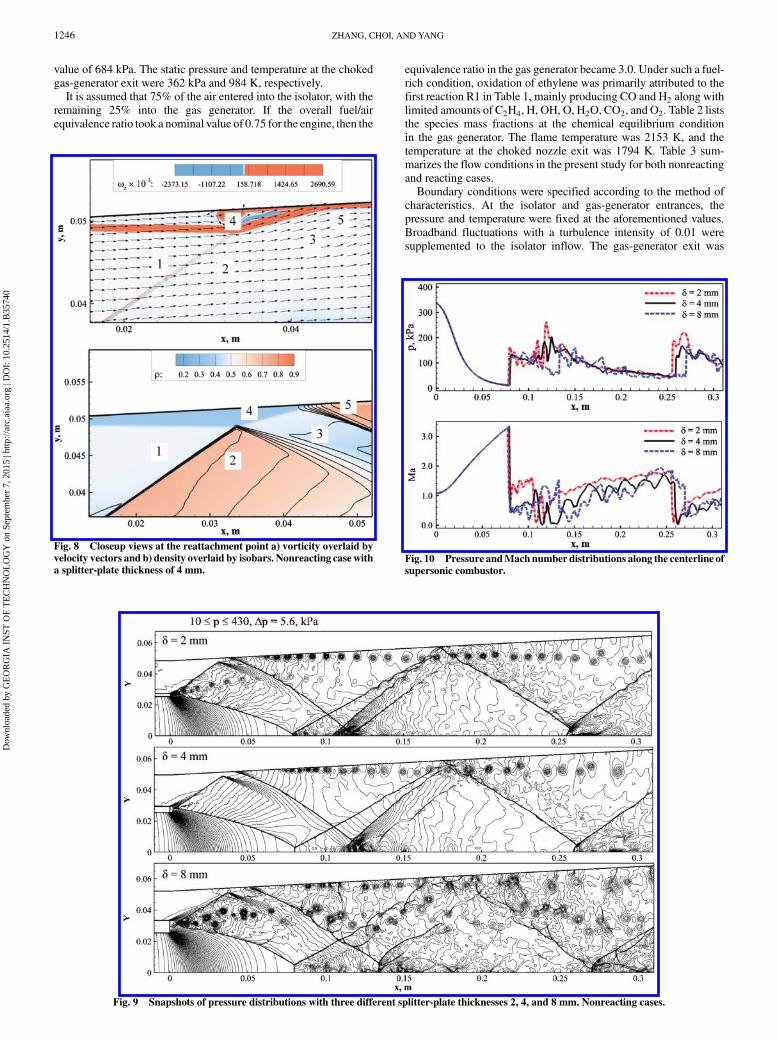
Fig. 8 Closeup views at the reattachment point a) vorticity overlaid byvelocity vectors and b) density overlaid by isobars. Nonreacting case witha splitter-plate thickness of 4 mm.
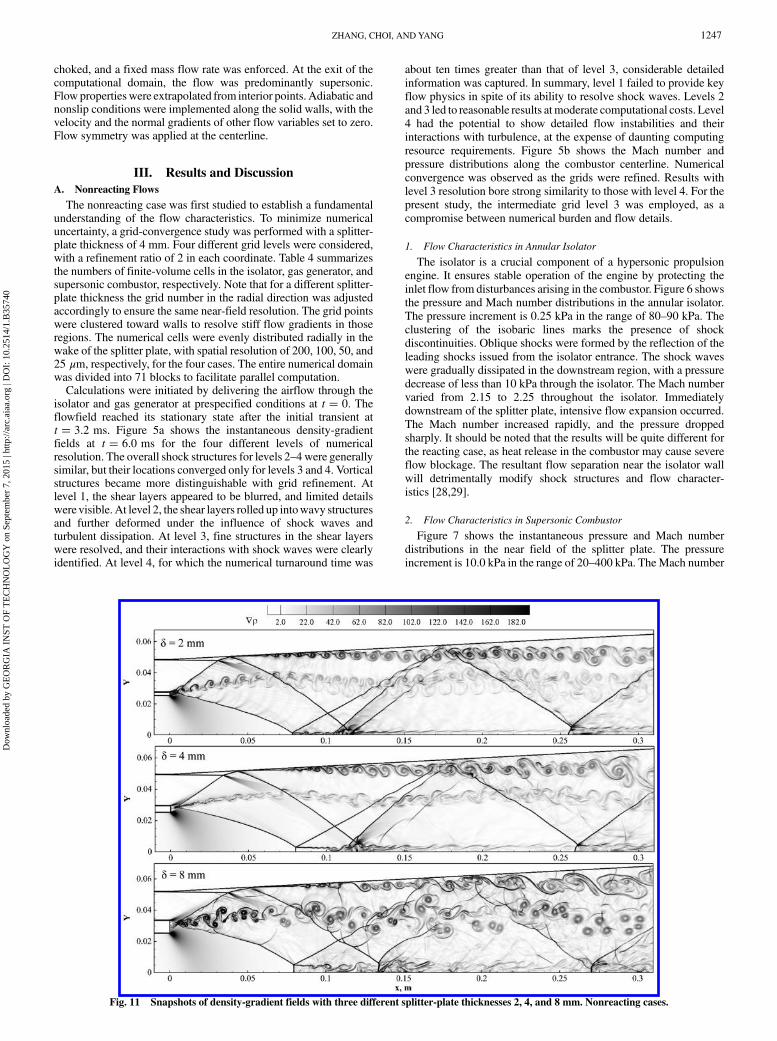
Fig. 9 Snapshots of pressure distributions with three different splitter-plate thicknesses 2, 4, and 8 mm. Nonreacting cases.
Fig. 10 Pressure andMachnumber distributions along the centerline of
supersonic combustor.
1246 ZHANG, CHOI, ANDYANG
Dow
nloa
ded
by G
EO
RG
IA I
NST
OF
TE
CH
NO
LO
GY
on
Sept
embe
r 7,
201
5 | h
ttp://
arc.
aiaa
.org
| D
OI:
10.
2514
/1.B
3574
0
choked, and a fixed mass flow rate was enforced. At the exit of thecomputational domain, the flow was predominantly supersonic.Flowpropertieswere extrapolated from interior points. Adiabatic andnonslip conditions were implemented along the solid walls, with thevelocity and the normal gradients of other flow variables set to zero.Flow symmetry was applied at the centerline.
III. Results and Discussion
A. Nonreacting Flows
The nonreacting case was first studied to establish a fundamentalunderstanding of the flow characteristics. To minimize numericaluncertainty, a grid-convergence study was performed with a splitter-plate thickness of 4 mm. Four different grid levels were considered,with a refinement ratio of 2 in each coordinate. Table 4 summarizesthe numbers of finite-volume cells in the isolator, gas generator, andsupersonic combustor, respectively. Note that for a different splitter-plate thickness the grid number in the radial direction was adjustedaccordingly to ensure the same near-field resolution. The grid pointswere clustered toward walls to resolve stiff flow gradients in thoseregions. The numerical cells were evenly distributed radially in thewake of the splitter plate, with spatial resolution of 200, 100, 50, and25 μm, respectively, for the four cases. The entire numerical domainwas divided into 71 blocks to facilitate parallel computation.Calculations were initiated by delivering the airflow through the
isolator and gas generator at prespecified conditions at t � 0. Theflowfield reached its stationary state after the initial transient att � 3.2 ms. Figure 5a shows the instantaneous density-gradientfields at t � 6.0 ms for the four different levels of numericalresolution. The overall shock structures for levels 2–4 were generallysimilar, but their locations converged only for levels 3 and 4. Vorticalstructures became more distinguishable with grid refinement. Atlevel 1, the shear layers appeared to be blurred, and limited detailswere visible. At level 2, the shear layers rolled up intowavy structuresand further deformed under the influence of shock waves andturbulent dissipation. At level 3, fine structures in the shear layerswere resolved, and their interactions with shock waves were clearlyidentified. At level 4, for which the numerical turnaround time was
about ten times greater than that of level 3, considerable detailedinformation was captured. In summary, level 1 failed to provide keyflow physics in spite of its ability to resolve shock waves. Levels 2and 3 led to reasonable results atmoderate computational costs. Level4 had the potential to show detailed flow instabilities and theirinteractions with turbulence, at the expense of daunting computingresource requirements. Figure 5b shows the Mach number andpressure distributions along the combustor centerline. Numericalconvergence was observed as the grids were refined. Results withlevel 3 resolution bore strong similarity to those with level 4. For thepresent study, the intermediate grid level 3 was employed, as acompromise between numerical burden and flow details.
1. Flow Characteristics in Annular Isolator
The isolator is a crucial component of a hypersonic propulsionengine. It ensures stable operation of the engine by protecting theinlet flow from disturbances arising in the combustor. Figure 6 showsthe pressure and Mach number distributions in the annular isolator.The pressure increment is 0.25 kPa in the range of 80–90 kPa. Theclustering of the isobaric lines marks the presence of shockdiscontinuities. Oblique shocks were formed by the reflection of theleading shocks issued from the isolator entrance. The shock waveswere gradually dissipated in the downstream region, with a pressuredecrease of less than 10 kPa through the isolator. The Mach numbervaried from 2.15 to 2.25 throughout the isolator. Immediatelydownstream of the splitter plate, intensive flow expansion occurred.The Mach number increased rapidly, and the pressure droppedsharply. It should be noted that the results will be quite different forthe reacting case, as heat release in the combustor may cause severeflow blockage. The resultant flow separation near the isolator wallwill detrimentally modify shock structures and flow character-istics [28,29].
2. Flow Characteristics in Supersonic Combustor
Figure 7 shows the instantaneous pressure and Mach numberdistributions in the near field of the splitter plate. The pressureincrement is 10.0 kPa in the range of 20–400 kPa. TheMach number
Fig. 11 Snapshots of density-gradient fields with three different splitter-plate thicknesses 2, 4, and 8 mm. Nonreacting cases.
ZHANG, CHOI, ANDYANG 1247
Dow
nloa
ded
by G
EO
RG
IA I
NST
OF
TE
CH
NO
LO
GY
on
Sept
embe
r 7,
201
5 | h
ttp://
arc.
aiaa
.org
| D
OI:
10.
2514
/1.B
3574
0

is colored between 0.2 and 3.2. Expansion waves stemming from theedges of the splitter plate were clearly observed. Flow separationoccurred at the diverging point of the combustor wall (x � 0). Sincethe pressure changed modestly from the isolator to the combustor,expansion waves emanating from the upper edge of the splitter platewere indistinct in this color scale. In contrast, awell-established semi-oval expansion zone appeared at the lower edge of the splitter plate.As the flow passed through this region, its pressure dropped to below80 kPa, and the Mach number rose above 3.0. Overexpansionoccurred immediately downstream of the splitter plate, and a conicaloblique shock formed to adjust the flowfield to match the isolatorflow. The resultant barrel shock then reflected at a Mach disk (astrong shock normal to the flow direction) near the centerline,generating oblique shocks and Mach reflections in the far field. Anoblique shock also appeared at the splitter-plate outer edge. It wasincident to the separated shear layer near the wall and led to anexpansion fan. The separated flow then reattached to the wall,forming a recirculation bubble and inducing another oblique shocknear the reattachment point.Figure 8 shows closeup views of the density and vorticity fields
near the reattachment point, with isobars and velocity vectors,respectively. The shear layer separating the near-wall, low-densityregion and the main stream is marked by a red strip of positivevorticity, an indication of counterclockwise motion. The incidentshock is manifested by a narrow zone featuring a stiff vorticitygradient. As the flow in zone 1 passed the oblique shock, it wascompressed and diverted to the shock direction in zone 2. As soon asthe shear layer met the incident shock, it bent toward and eventuallyreattached to the wall. The incident shock was reflected into anexpansion fan, separating zones 2 and 3. The density and velocitymismatches between zones 3 and 4 led to the formation of a contactdiscontinuity indicated by a vorticity layer between the two zones.The flow in zone 3was overexpanded.Another oblique shock formednear the attachment point, and the near-wall vorticity rolled up into asecondary shear layer in zone 5, as shown in Fig. 7.
3. Effect of Splitter-Plate Thickness
Figure 9 shows snapshots of the pressure field with three differentsplitter-plate thicknesses of 2, 4, and 8 mm. The pressure is in therange of 10–430 kPa with an increment of 5.6 kPa. As the splitter-plate thickness increased, the incidence location of the outer obliqueshock on the combustor wall was delayed, the region enclosed by theinner oblique shocks expands, and the size of the first Mach diskincreased. Figure 10 shows the pressure and Mach numberdistributions along the centerline of the combustor. The expansionzone is marked by a smooth rise in the Mach number and a gradualdrop in pressure from x � 0 to 0.08 cm. Results with differentsplitter-plate thicknesses converge in this region. The distancebetween the gas-generator nozzle exit and the firstMach diskHM canbe estimated by an empirical correlation [30] as a function of the ratioof the nozzle stagnation pressure ptot to the effective backpressurepb;eff ,
HM
d� 0.67
�����������Ptot
Pb;eff
s
where d is the diameter of the exit nozzle. In the current cases, d is5.08 cm, and ptot and pb;eff are 684 and 115 kPa, respectively.HM isestimated to be 0.08 m, which matches the simulations well. As thesplitter plate thickens, the size of the expansion zone increased, andthe incidence angle of the barrel shock decreased, leading to a largerfirst Mach disk. Since the downstream flowfield was adjusted byshocks and contact discontinuities, the locations of the second andsubsequentMach disks varied among the three plots; the discrepancyexceeded 0.01 m in the third. Overall, the case with a splitter-platethickness of 2mmhad the highest bulkMach number and the shortestinterval between two consecutive shock reflections.Figure 11 compares the density-gradient distributions with
different splitter-plate thicknesses. The primary mixing layer startedimmediately downstream of the splitter plate, between the outer and
the inner oblique shocks. It grew laterally, intersected with and wasdiverted by shock waves, and diffused into the mainstream. Theincident shock waves were reflected from either the combustor wallor the Mach disk. Secondary shear layers were generated by theshock-wave/shear-layer interactions. Combined, these discontinu-ities had significant impacts on the flow and flame dynamics. Aneffective resolution of these structures was necessary for a thoroughexamination of the mixing and combustion process. As the splitterplate thickens, the shear layers expanded, and their interactions withshocks were intensified, creating broader low-speed, high-temper-ature regions.Of the subsonic zones, the one in the wake of the splitter plate was
most important. Figure 12 shows the vorticity distributions andvelocity vectors in the near field. As the flow passed the splitter plate,sudden expansion took place and led to boundary-layer separation.The separated flows with negative vorticity (clockwise motion) fromthe isolator and positive vorticity (counterclockwise motions) fromthe gas generator ran toward each other and merged at an axialdistance of around 1.5, 2.2, and 3 mm, respectively, for the threesplitter-plate thicknesses. Recirculating flows were created upstreamof these intersection points, and mixing layers formed downstream.The behaviors of flow expansion varied with the splitter-platethickness as follows. First, the upper and the lower recirculating
Fig. 12 Snapshots of vorticity and velocity vectors in the near field withthree different splitter-plate thicknesses 2, 4, and 8 mm. Nonreactingcases.
1248 ZHANG, CHOI, ANDYANG
Dow
nloa
ded
by G
EO
RG
IA I
NST
OF
TE
CH
NO
LO
GY
on
Sept
embe
r 7,
201
5 | h
ttp://
arc.
aiaa
.org
| D
OI:
10.
2514
/1.B
3574
0

zones merged for the 2 mm plate, made contact behind the 4 mmplate, and separated downstream of the 8 mm plate. Second, thevorticity was stratified in the 2 and 4 mm cases. In contrast, thestratification broke down in the 8 mm case at an axial distance ofaround 5mm.These differences could have strong effects on the near-field mixing and ignition.
B. Reacting Flows
Once a fully developed nonreacting flowfield was achieved,oxidation of ethylene was activated in the gas generator. Productsfrom the fuel-rich combustion were injected into the supersoniccombustor. Data were collected after the initial transient wascomplete and the flowfield had reached its stationary state.
1. Flow and Flame Characteristics in Combustor
For comparison purposes, a supplemental case with ethyleneoxidation in the gas generator but with frozen chemistry in thesupersonic combustor was treated for a splitter-plate thickness of4 mm. It was referred to as the semireacting case hereafter. Figure 13shows snapshots of the temperature field in the semireacting case T1
and the reacting caseT2 at the same time instant. As the gas-generatorproducts entered the main combustor, the temperature T1
immediately downstream of the splitter plate rose to above 1000 K,as shown in Fig. 13a. Autoignition thus occurred, and no externalstimulus was required. As compared to Fig. 13a, the fully reactingcaseT2 in Fig. 13b gained a bulk increase from chemical heat release.Note that the ethylene/air combustion had an adiabatic flame
Fig. 13 Snapshots of temperature distributions with a splitter-plate thickness of 4 mm a) semireacting case T1, b) reacting case T2, and c) T2 − T1.
Fig. 14 Snapshots of density-gradient fields for the semireacting and reacting cases with a splitter-plate thickness of 4 mm.
ZHANG, CHOI, ANDYANG 1249
Dow
nloa
ded
by G
EO
RG
IA I
NST
OF
TE
CH
NO
LO
GY
on
Sept
embe
r 7,
201
5 | h
ttp://
arc.
aiaa
.org
| D
OI:
10.
2514
/1.B
3574
0

temperature of 2369 K at stoichiometric conditions and 1 atm. With
T2 exceeding 2100 K in moderately large zones and excessive air
herein, it is believed that combustion was fully established in the
current calculation.Figure 13c shows the difference between T1 and T2. Negative
values colored in blue indicate flow unsteadiness. Positive values aremarked by isolines in the range of 200–1600 K at an increment of200 K. The value of T2 − T1 represents reaction intensity and variesrapidly in the narrow zones across the mixing layer. The localizedheat release affected flow structures and vice versa. Figure 14 showsthe corresponding density-gradient contours. The shock systemresembles its nonreacting counterpart in Fig. 11, albeit with slightupstream shifts of reflection locations. The overall unsteadiness inthe shear layers was suppressed as a result of the increased viscosityat an elevated temperature, especially on the fuel side. Thecombustion-induced thermodynamic changes were manifold:1) Viscous layers grew near reaction zones and hindered flowentrainment. 2) As the transport coefficients increased, fuel andoxygen were supplied to the reactions faster provided with properscalar concentrations. 3) Because of local density decrease, theflowfield was more sensitive to incident instabilities, as suggested bya wavier near-field shear layer in the reacting case.Figure 15 shows instantaneous distributions of the pressure, Mach
number, vorticity, and mixture fraction. Large pressure variationsmark the locations of shock waves. Heat release in the mixing layer
drove the local flow evolution toward the sonic state. Vorticityproduction was enabled by shock-induced baroclinic torques. Theensuing intensive motions in the radial direction enhanced flowentrainment and promoted shear-layer transient, from a hydro-dynamic instability induced small-scale sinusoidal motion to thelarge-scale fluctuations. To trace reactants in the current non-premixed combustion, themixture fractionwas calculated as the totalelement fraction ofC andH normalized by the amount initially in thegas-generator stream. Only values in the range of 0.1–0.9 are shown.Since the gas generator had a total ethylene/air equivalence ratio of3.0, the mixture fracture herein corresponded roughly to anequivalence ratio of 0.3–2.7. Thevalue is commonly considered to bewithin the ethylene/air flammability limit. Note that therewere strongcorrelations between the temperature increase in Fig. 13c and themixture-fraction distribution in Fig. 15, suggesting that mixing playsa critical role in dictating chemical reactions.Analyses of reacting flows were further performed with splitter-
plate thicknesses of 2 and 8mmwith the other conditions unchanged.Figures 16 and 17 present distributions of the temperature and CO2
mass fraction for three different thicknesses, respectively. For the2 mm case, the overall flow unsteadiness was relatively weak, with aconcentrated mixing layer, especially in the far field after shockpenetrations. As a result, the flame was restricted to a thin region,indicating low combustion efficiency and robustness. For the 8 mmcase, the mixing layer was much fuller, with a higher bulk temper-
Fig. 15 Snapshots of pressure, Mach number, vorticity, and mixture-fraction distributions. Reacting case with a splitter-plate thickness of 4 mm.
1250 ZHANG, CHOI, ANDYANG
Dow
nloa
ded
by G
EO
RG
IA I
NST
OF
TE
CH
NO
LO
GY
on
Sept
embe
r 7,
201
5 | h
ttp://
arc.
aiaa
.org
| D
OI:
10.
2514
/1.B
3574
0
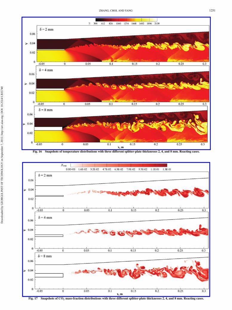
Fig. 16 Snapshots of temperature distributions with three different splitter-plate thicknesses 2, 4, and 8 mm. Reacting cases.
Fig. 17 Snapshots of CO2 mass-fraction distributions with three different splitter-plate thicknesses 2, 4, and 8 mm. Reacting cases.
ZHANG, CHOI, ANDYANG 1251
Dow
nloa
ded
by G
EO
RG
IA I
NST
OF
TE
CH
NO
LO
GY
on
Sept
embe
r 7,
201
5 | h
ttp://
arc.
aiaa
.org
| D
OI:
10.
2514
/1.B
3574
0
ature. For all three cases, only limited amounts of CO2 productionwere observed in the recirculation zone.
2. Flow and Flame Characteristics in Near Field
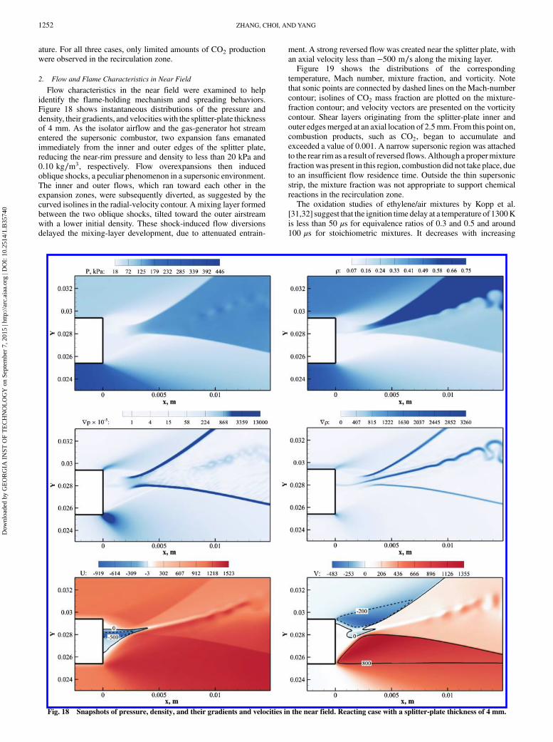
Flow characteristics in the near field were examined to helpidentify the flame-holding mechanism and spreading behaviors.Figure 18 shows instantaneous distributions of the pressure anddensity, their gradients, and velocitieswith the splitter-plate thicknessof 4 mm. As the isolator airflow and the gas-generator hot streamentered the supersonic combustor, two expansion fans emanatedimmediately from the inner and outer edges of the splitter plate,reducing the near-rim pressure and density to less than 20 kPa and0.10 kg∕m3, respectively. Flow overexpansions then inducedoblique shocks, a peculiar phenomenon in a supersonic environment.The inner and outer flows, which ran toward each other in theexpansion zones, were subsequently diverted, as suggested by thecurved isolines in the radial-velocity contour. A mixing layer formedbetween the two oblique shocks, tilted toward the outer airstreamwith a lower initial density. These shock-induced flow diversionsdelayed the mixing-layer development, due to attenuated entrain-
ment. A strong reversed flow was created near the splitter plate, withan axial velocity less than −500 m∕s along the mixing layer.Figure 19 shows the distributions of the corresponding
temperature, Mach number, mixture fraction, and vorticity. Notethat sonic points are connected by dashed lines on the Mach-numbercontour; isolines of CO2 mass fraction are plotted on the mixture-fraction contour; and velocity vectors are presented on the vorticitycontour. Shear layers originating from the splitter-plate inner andouter edgesmerged at an axial location of 2.5mm. From this point on,combustion products, such as CO2, began to accumulate andexceeded a value of 0.001. A narrow supersonic region was attachedto the rear rim as a result of reversed flows.Although a propermixturefractionwas present in this region, combustion did not take place, dueto an insufficient flow residence time. Outside the thin supersonicstrip, the mixture fraction was not appropriate to support chemicalreactions in the recirculation zone.The oxidation studies of ethylene/air mixtures by Kopp et al.
[31,32] suggest that the ignition time delay at a temperature of 1300Kis less than 50 μs for equivalence ratios of 0.3 and 0.5 and around100 μs for stoichiometric mixtures. It decreases with increasing
Fig. 18 Snapshots of pressure, density, and their gradients and velocities in the near field. Reacting case with a splitter-plate thickness of 4 mm.
1252 ZHANG, CHOI, ANDYANG
Dow
nloa
ded
by G
EO
RG
IA I
NST
OF
TE
CH
NO
LO
GY
on
Sept
embe
r 7,
201
5 | h
ttp://
arc.
aiaa
.org
| D
OI:
10.
2514
/1.B
3574
0

Fig. 19 Snapshots of temperature, Mach number, mixture fraction, and vorticity in the near field. Reacting case with a splitter-plate thickness of 4 mm.
Fig. 20 Snapshots of temperature, Mach number, mixture fraction, and vorticity in the near field. Reacting case with a splitter-plate thickness of 2 mm.
ZHANG, CHOI, ANDYANG 1253
Dow
nloa
ded
by G
EO
RG
IA I
NST
OF
TE
CH
NO
LO
GY
on
Sept
embe
r 7,
201
5 | h
ttp://
arc.
aiaa
.org
| D
OI:
10.
2514
/1.B
3574
0
temperatures. Since ethylene oxidation in the gas generator producesa mixture rich in free radicals with a flame temperature over 1600 K,the ignition time delay is largely reduced. Autoignition is expected,so long as a proper mixture is formed in the region with a moderateflow residence.Figure 20 shows instantaneous distributions of the temperature,
Mach number, mixture fraction, and vorticity with a splitter-platethickness of 2 mm. Compared to Fig. 19, the near-field recirculationzone shrank but remains subsonic. CO2 was detected, indicating theexistence of an attached flame. This phenomenon may be attributedto the fact that, as the splitter-plate thickness decreased, theexpansions of the two incoming streams weakened. With a velocityon the order of 10 m∕s and a characteristic length being the platethickness of 2mm, the flow residence time in the subsonic regionwason the order of 100 μs. A combustion-favorable environment wascreated in the splitter-platewake flow, and autoignition occurred oncethe mixture fraction fell in the flammability region.Figure 21 shows snapshots of the temperature, Mach number,
mixture fraction, and vorticity fields with a splitter-plate thickness of8 mm. Such a geometry change caused strong flow expansion andunsteadiness. The resultant stretching in the near-field mixing layerprohibited any chemical reactions. Immediately downstream of thesplitter plate, a proper mixture fraction was not correlated with thelow-speed flow; in other regions in which the flow speed wassufficiently low, mixing was not well established, and the flame wasdetached from the rim.In all, the recirculating wake flow behind the splitter plate was
crucial in determining themixing behaviors of the coflow fuel and air.It was not, however, sufficient to stabilize the flame in the presentstudy. Its size and shape were strongly affected by splitter-platethickness, due to rapid flow expansion under supersonic conditions.Significant flow mixing and associated dynamics commenceddownstream of the wake region. Depending on the local mixing andflow properties, autoignition occurred either in the wake flow or atsome distance downstream of the mixing layer. For the former, the
flame appeared to be stabilized by the recirculation zone. In the lattercase, a lifted flame occurred and was intermittently connected to thewake through thin reacting filaments. Sporadic autoignition occurredin the later mixing layer to sustain stable combustion in the system.
IV. Conclusions
Supersonic flow and flame characteristics were numericallyinvestigated for an ethylene and air coflow with a splitter plate in adual-combustion ramjet engine environment. Various flow andcombustion phenomena were explored with three different splitter-plate thicknesses of 2, 4, and 8 mm. Special attention was given toflame stabilization immediately downstream of the splitter plate andthe ensuing spreading process in the mixing layer.Analysis was first performed for nonreacting cases. The stream
from the gas generator behaves as an underexpanded supersonic jet asit enters thewall-confined supersonic combustor, inducing a series ofcomplex flow structures, including expansion and compressionshock waves, boundary-layer separation, and reattachment. In thenear field, a recirculation zone occurs downstream of the splitter platealong with two oblique shocks stemming from the plate edges.Further downstream, a supersonic mixing layer forms between thetwo oblique shocks, and its development is influenced by thediscontinuities that are intrinsic to supersonic environments.The combustion cases were treated using a laminar chemistry
model. The overall reacting flowfield bears close resemblance to itsnonreacting counterpart, except for moderate suppression of themixing-layer development due to heat release. The reaction zonestarts downstream of the splitter plate and spreads over the entiremixing layer. The spatial location of ignition is dictated by local flowexpansion and mixing effectiveness. For a thin splitter plate, theflame is attached, whereas lifted flames are observed for thickerplates, a phenomenon that can be attributed to the strong flowexpansion with increasing plate thickness. On the other hand, as thesplitter plate thickens, mixing dynamics is enhanced, leading tomorecomplete combustion.
Fig. 21 Snapshots of temperature, Mach number, mixture fraction, and vorticity in the near field. Reacting case with a splitter-plate thickness of 8 mm.
1254 ZHANG, CHOI, ANDYANG
Dow
nloa
ded
by G
EO
RG
IA I
NST
OF
TE
CH
NO
LO
GY
on
Sept
embe
r 7,
201
5 | h
ttp://
arc.
aiaa
.org
| D
OI:
10.
2514
/1.B
3574
0
Acknowledgments
This work was sponsored by the William R. T. Oakes Endowmentat the Daniel Guggenheim School of Aerospace Engineering at theGeorgia Institute of Technology.
References
[1] Curran, E. T., “Scramjet Engines: The First Forty Years,” Journal of
Propulsion and Power, Vol. 17, No. 6, 2001, pp. 1138–1148.doi:10.2514/2.5875
[2] Waltrup, P. J., White, M. E., Zarlingo, F., and Gravlin, E. S., “History ofU.S. Navy Ramjet, Scramjet, and Mixed-Cycle Propulsion Develop-ment,” Journal of Propulsion and Power, Vol. 18, No. 1, 2002, pp. 14–27.doi:10.2514/2.5928
[3] Fry, R. S., “A Century of Ramjet Propulsion Technology Evolution,”Journal of Propulsion and Power, Vol. 20, No. 1, 2004, pp. 27–58.doi:10.2514/1.9178
[4] Segal, C., The Scramjet Engine: Processes and Characteristics,Cambridge Univ. Press, New York, 2009.
[5] Billig, F. S., Waltrup, P. J., and Stockbridge, R. D., “Integral-RocketDual Combustion Ramjets: A New Propulsion Concept,” Journal of
Spacecraft, Vol. 17, No. 5, 1980, pp. 416–424.doi:10.2514/3.57760
[6] Billig, F. S., “Supersonic Combustion Ramjet Missile,” Journal of
Propulsion and Power, Vol. 11, No. 6, 1995, pp. 1139–1146.doi:10.2514/3.23952
[7] Waltrup, P. J., “Liquid-Fueled Supersonic Combustion Ramjets: AResearch Perspective,” Journal of Propulsion and Power, Vol. 3, No. 6,1987, pp. 515–524.doi:10.2514/3.23019
[8] Colket, M. B., III, and Spadaccini, L. J., “Scamjet Fuels AutoignitionStudy,” Journal of Propulsion andPower, Vol. 17,No. 2, 2001, pp. 315–323.doi:10.2514/2.5744
[9] Puri, P.,Ma, F.-H., Choi, J.-Y., andYang, V., “Ignition Characteristics ofCracked JP-7 Fuel,” Combustion and Flame, Vol. 142, No. 4, 2005,pp. 454–457.doi:10.1016/j.combustflame.2005.06.001
[10] Papamoschou, D., and Roshko, A., “The Compressible Turbulent ShearLayer: An Experimental Study,” Journal of Fluid Mechanics, Vol. 197,No. 1, 1988, pp. 453–477.doi:10.1017/S0022112088003325
[11] Dimotakis, P. E., “Turbulent Free Shear Layer Mixing andCombustion,” High Speed Propulsion Systems, edited by Murthy, S.N. B., and Curran, E. T., Vol. 137, Progress in Astronautics andAeronautics, AIAA, Washingdon, D.C., 1991, pp. 265–340.
[12] Clemens, N. T., and Mungal, M. G., “Large-Scale Structure andEntrainment in the Supersonic Mixing Layer,” Journal of Fluid
Mechanics, Vol. 284, No. 1, 1995, pp. 171–216.doi:10.1017/S0022112095000310
[13] Fernández-Tarrazo, E., Vera, M., and Liñánc, A., “Liftoff and Blowoffof a Diffusion Flame Between Parallel Streams of Fuel and Air,”Combustion and Flame, Vol. 144, Nos. 1–2, 2006, pp. 261–276.doi:10.1016/j.combustflame.2005.07.012
[14] Kurdyumov, V., and Matalon, M., “Stabilization and Onset ofOscillation of an Edge-Flame in the Near-Wake of a Fuel Injector,”Proceedings of the Combustion Institute, Vol. 31, No. 1, 2007, pp. 909–917.doi:10.1016/j.proci.2006.07.248
[15] Clemens, N., andMungal,M., “Two- and Three-Dimensional Effects inthe Supersonic Mixing Layer,” AIAA Journal, Vol. 30, No. 4, 1992,pp. 973–981.doi:10.2514/3.11016
[16] Yu, K. H., Parr, T. P., and Schadow, K. C., “Planar Mie ScatteringVisualization of Reacting and Nonreacting Supersonic Coaxial Jets,”International Journal of EnergeticMaterials andChemical Propulsion,Vol. 3, Nos. 1–6, 1994, pp. 504–517.doi:10.1615/IntJEnergeticMaterialsChemProp.v3.i1-6.520
[17] Otakeyama, Y., Takeshi Yokomori, T., and Mizomoto, M., “Stability ofCH4 − N2∕Air Jet Diffusion Fame for Various Burner RimThicknesses,” Proceedings of the Combustion Institute, Vol. 32,No. 1, 2009, pp. 1091–1097.doi:10.1016/j.proci.2008.05.002
[18] Menter, F. R., “Two-Equation Eddy-Viscosity Turbulence Models forEngineering Applications,” AIAA Journal, Vol. 32, No. 8, 1994,pp. 1598–1605.doi:10.2514/3.12149
[19] Spalart, P. R., Jou,W.-H., Strelets, M., and Allmaras, S. R., “Commentson the Feasibility of LES for Wings, and on a Hybrid RANS/LESApproach,” Advances in DNS/LES, Greyden Press, Columbus, OH1997, pp. 137–148.
[20] Strelets, M., “Detached Eddy Simulation of Massively SeparatedFlows,” AIAA Paper 2001-0879, 2001.
[21] Choi, J. Y., Jeung, I. S., and Yoon, Y., “Numerical Study of ScramAccelerator Starting Characteristics,” AIAA Journal, Vol. 36, No. 6,1998, pp. 1029–1038.doi:10.2514/2.476
[22] Singh, D. J., and Jachimowski, C. J., “Quasi-Global ReactionModel forEthylene Combustion,” AIAA Journal, Vol. 32, No. 1, 1994, pp. 213–216.doi:10.2514/3.11972
[23] Jachimowski, C. J., “An Experimental and Analytical Study ofAcetylene and Ethylene Oxidation Behind Shock Waves,” Combustionand Flame, Vol. 29, No. 1, 1977, pp. 55–66.doi:10.1016/0010-2180(77)90093-1
[24] Evans, J. S., Schexnayder, C. J., Jr., andBeach,H. L., Jr., “Application ofa Two-Dimensional Parabolic Computer Program to Prediction ofTurbulent Reacting Flows,” NASA TP-1169, 1978.
[25] Evans, J. S., and Schexnayder, C. J., “Influence of Chemical Kineticsand Unmixedness on Burning in Supersonic Hydrogen Flames,” AIAAJournal, Vol. 18, No. 2, 1980, pp. 188–193.doi:10.2514/3.50747
[26] Möbus, H., Gerlinger, P., and Brüggermann, D., “Scalar and JointScalar-Velocity-FrequencyMonte Carlo PDF Simulation of SupersonicCombustion,” Combustion and Flame, Vol. 132, Nos. 1–2, 2003,pp. 3–24.doi:10.1016/S0010-2180(02)00428-5
[27] Koo, H., Donde, P., and Raman, V., “A Quadrature-Based LES/Transported Probability Density Function Approach for ModelingSupersonic Combustion,” Proceedings of the Combustion Institute,Vol. 33, No. 2, 2011, pp. 2203–2210.doi:10.1016/j.proci.2010.07.058
[28] Li, J., Zhang, L., Choi, J.-Y., Yang, V., and Lin, K. C., “IgnitionTransients in a Scramjet Enginewith Air Throttling, Part 1: NonreactingFlow,” Journal of Propulsion and Power, Vol. 30, No. 2, 2014, pp. 438–448.doi:10.2514/1.B34763
[29] Li, J., Zhang, L., Choi, J.-Y., Yang, V., and Lin, K. C., “IgnitionTransients in a Scramjet Engine with Air Throttling Part II: ReactingFlow,” Journal of Propulsion and Power, Vol. 31, No. 1, 2015, pp. 79–88.doi:10.2514/1.B35269
[30] Ashkenas, H., and Sherman, F. S., “The Structure and Utilization ofSupersonic Free Jets in Low Density Wind Tunnels,” Rarefied Gas
Dynamics Volume II, Academic Press, New York, 1966, pp. 84–105.[31] Kopp, M. M., Donato, N. S., Petersen, E. L., Metcalfe, W. K., Burke, S.
M., and Curran, H. J., “Oxidation of Ethylene-Air Mixtures at ElevatedPressures, Part 1: Experimental Results,” Journal of Propulsion and
Power, Vol. 30, No. 3, 2014, pp. 790–798.doi:10.2514/1.B34890
[32] Kopp,M.M., Petersen, E. L.,Metcalfe,W.K., Burke, S.M., andCurran,H. J., “Oxidation of Ethylene-AirMixtures at Elevated Pressures, Part 2:Chemical Kinetics,” Journal of Propulsion and Power, Vol. 30, No. 3,2014, pp. 799–811.doi:10.2514/1.B34891
C. SegalAssociate Editor
ZHANG, CHOI, ANDYANG 1255
Dow
nloa
ded
by G
EO
RG
IA I
NST
OF
TE
CH
NO
LO
GY
on
Sept
embe
r 7,
201
5 | h
ttp://
arc.
aiaa
.org
| D
OI:
10.
2514
/1.B
3574
0