Superlift Part No. 5120 - Jeep Parts & Accessories for ... · PDF file2003 and newer JEEP TJ...
13
FORM #5120.04-020904 PRINTED IN U.S.A. PAGE 1 OF 13 SUPERLIFT SUSPENSION SYSTEMS 300 Huey Lenard Loop Rd. West Monroe, Louisiana 71292 Phone: (318) 397-3000 Sales / Tech: 1-800-551-4955 FAX: (318) 397-3040 Web Site: www.superlift.com Superlift Part No. 5120 - 4” lift system for 2003 and newer JEEP TJ with coil spring suspension INSTALLATION INSTRUCTIONS INTRODUCTION Installation requires a professional mechanic. Prior to beginning, inspect the vehicles steering, driveline, and brake systems, paying close attention to the track bar, suspension link arms and bushings, anti-sway bars and bushings, tie rod ends, pitman arm, ball joints and wheel bearings. Also check the steering sector-to-frame and all suspension-to-frame attaching points for stress cracks. The overall vehicle must be in excellent working condition; repair or replace all worn parts. Read instructions several times before starting. Be sure you have all needed parts and know where they install. Read each step completely as you go. NOTES: If the optional Rockrunner System is being installed, refer to those instructions before proceeding. • An inclinometer, or similar angle measuring tool, is required for a rear driveshaft angle reading. If this tool is unavailable, proper shaft angle can be attained by trial and error. • Front-end realignment is necessary. • A factory service manual should be on hand for reference. The manual will contain fastener torque specs, assembly techniques, and special tool requirements that are unique to this particular year and model vehicle. • Do not add or fabricate any components to gain additional suspension height. • Any welding must be performed by a professional certified welder. • After drilling, file smooth any burrs and sharp edges or stress cracks may develop. • Paint or undercoat all exposed metal surfaces. • Prior to attaching components, be sure mating surfaces are free of grease, grit, oil, undercoating, etc. • A torque specification in foot pounds is shown in parenthesis “( )” after each fastener. • Use the check-off box “” found at each step to help keep your place. Two “” denotes that one check-off box is for the driver side and one is for the passenger side. • An arrow on diagrams indicates which direction is towards “front of vehicle”. • Retain all factory hardware for reuse, unless otherwise specified.
Transcript of Superlift Part No. 5120 - Jeep Parts & Accessories for ... · PDF file2003 and newer JEEP TJ...
FORM #5120.04-020904 PRINTED IN U.S.A. PAGE 1 OF 13
SUPERLIFT SUSPENSION SYSTEMS 300 Huey Lenard Loop Rd.
West Monroe, Louisiana 71292 Phone: (318) 397-3000
Sales / Tech: 1-800-551-4955 FAX: (318) 397-3040
Web Site: www.superlift.com
Superlift Part No. 5120 - 4” lift system for 2003 and newer JEEP TJ with coil spring suspension
INSTALLATION INSTRUCTIONS
INTRODUCTION Installation requires a professional mechanic. Prior to beginning, inspect the vehicles steering, driveline, and brake systems, paying close attention to the track bar, suspension link arms and bushings, anti-sway bars and bushings, tie rod ends, pitman arm, ball joints and wheel bearings. Also check the steering sector-to-frame and all suspension-to-frame attaching points for stress cracks. The overall vehicle must be in excellent working condition; repair or replace all worn parts. Read instructions several times before starting. Be sure you have all needed parts and know where they install. Read each step completely as you go. NOTES: If the optional Rockrunner System is being installed, refer to those instructions before proceeding. • An inclinometer, or similar angle measuring tool, is required for a rear driveshaft angle
reading. If this tool is unavailable, proper shaft angle can be attained by trial and error.
• Front-end realignment is necessary.
• A factory service manual should be on hand for reference. The manual will contain fastener torque specs, assembly techniques, and special tool requirements that are unique to this particular year and model vehicle.
• Do not add or fabricate any components to gain additional suspension height.
• Any welding must be performed by a professional certified welder.
• After drilling, file smooth any burrs and sharp edges or stress cracks may develop.
• Paint or undercoat all exposed metal surfaces. • Prior to attaching components, be sure mating surfaces are free of grease, grit, oil,
undercoating, etc.
• A torque specification in foot pounds is shown in parenthesis “( )” after each fastener.
• Use the check-off box “ ” found at each step to help keep your place. Two “ ” denotes that one check-off box is for the driver side and one is for the passenger side.
• An arrow on diagrams indicates which direction is towards “front of vehicle”.
• Retain all factory hardware for reuse, unless otherwise specified.
FORM #5120.04-020904 PRINTED IN U.S.A. PAGE 2 OF 13
PARTS LIST The part number is stamped into each part or printed on an adhesive label. Identify each part and place the appropriate mounting hardware with it. PART NO DESCRIPTION ATTACHING HARDWARE (Qty.- if more than one) (Qty.) 01-550..........................(2) front coil spring 01-551..........................(2) rear coil spring 9003.............................(2) compression stop extension... (2) 10mm x 100mm bolt
55-01-5073...................(2) lower trailing link, front ........... (8) bushing half (4) sleeve NOTE: Trailing links are located in separate kit box #5073. 55-03-5064...................rear track bar bracket .................. (1) 7/16" x 1" bolt (1) 7/16" Nyloc nut (2) 5/16" x 3/4" bolt (2) 5/16" Nyloc nut 55-06-5064...................torque shaft bracket..................... (2) 1/4” x 1” tapered allen head bolt (2) 1/4” nyloc nut 55-01-5067...................(2) anti-sway bar bracket, front .... (2) 3/8” x 1-1/2” bolt (2) 3/8” nyloc nut 55-09-5064...................(2) anti-sway bar link, front .......... (2) 7/16” x 2-3/4” bolt (2) 7/16” Nyloc nut (4) poly bushing (4) sleeve 55-07-5120...................(2) transfer case drop bracket ..... (6) 12mm x 80mm bolt 55-08-5120...................(2) engine mount spacer plate 55-10-5064...................(2) anti-sway bar link, rear ........... (4) poly bushing (4) 1/2” ID poly vinyl sleeve 19-5100........................(2) poly compression stop, front 55-13-5100...................rear shock bracket extension,...... (1) 3/8” x 1” bolt driver side (2) 3/8” SAE washer (1) 3/8” nyloc nut (1) 1/2” x 2-3/4” bolt (2) 1/2” SAE washer (1) 1/2” stover nut (1) 5/8” OD x 1/2” ID x 1-3/8” sleeve
FORM #5120.04-020904 PRINTED IN U.S.A. PAGE 3 OF 13
55-14-5100 .................. rear shock bracket extension, ......(1) 3/8” x 1” bolt passenger side (2) 3/8” SAE washer (1) 3/8” nyloc nut (1) 1/2” x 2-3/4” bolt (2) 1/2” SAE washer (1) 1/2” stover nut (1) 5/8” OD x 1/2” ID x 1-3/8” sleeve 1106 ............................ pitman arm ...................................cotter pin, 1/8" x 2" 03-5062 ....................... (2) cam bolt assembly 85306........................... (2) front shock absorber ...............(2) shock hardware pack 85115........................... (2) rear shock absorber................(2) shock hardware pack 01-86010 ..................... (4) yellow shock absorber boot ....(4) shock boot cable tie 0034 ............................ Superlift badge.............................alcohol wipe pad
FRONT DISASSEMBLY 1) PREPARE VEHICLE... Place vehicle in low gear or park. With the suspension supporting vehicle weight, and the
vehicle on level ground, use an inclinometer to take a rear driveshaft angle reading. One of the last installation steps will be to reset the driveshaft angle as close as possible to this reading.
Place vehicle in neutral. Raise front of vehicle with a jack, and secure a jack stand behind
the lower link arms, beneath each frame rail. Ease the frame down onto the stands. Support the outboard end of the driver and passenger side axle tube with a floor jack; the frame is to remain on the stands.
2) TRACK BAR...
Remove the bolt at the bottom / axle end of the track bar. The upper / frame end is not disconnected.
3) DRAG LINK and PITMAN ARM... Remove the cotter pin and nut that connects the drag link-to pitman arm. Use a puller tool to
detach the link from the arm.
Remove the nut and washer from the steering gear shaft, then use a puller tool to remove the pitman arm from the shaft.
4) SHOCK ABSORBERS...
Disconnect and discard the factory shocks. 5) ANTI-SWAY BAR LINKS...
On each side, disconnect the sway bar link from the axle bracket and the bar body. 6) SKID PLATE…
Remove and discard the factory front skid plate that is forward of the “belly pan” for the transmission.
FORM #5120.04-020904 PRINTED IN U.S.A. PAGE 4 OF 13
7) LOWER LINK ARMS... Cam bolts attach the lower links to the front axle housing. Front end alignment is altered as
the bolts are rotated. Paint or scribe alignment marks on each cam bolt and axle bracket so the bolts can later be returned to their original position.
On each side, remove the cam bolt assembly from the link’s axle end. Then remove the
attaching bolt at the rear of the lower link arm where it connects to the frame rail and remove the link. Save all hardware for reuse.
8) COIL SPRINGS...
Lower the jack/axle assembly until the coil springs are free from their upper seats. A retainer clip must be removed at the base of the driver side coil. Remove the coils.
FRONT ASSEMBLY
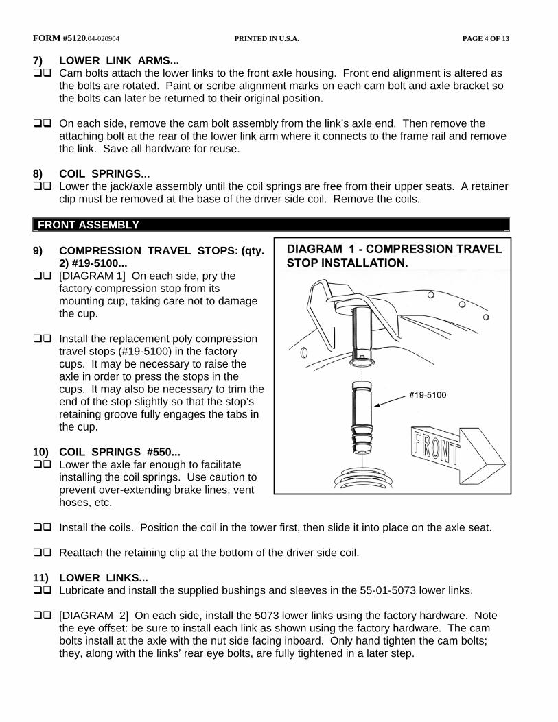
9) COMPRESSION TRAVEL STOPS: (qty.
2) #19-5100... [DIAGRAM 1] On each side, pry the
factory compression stop from its mounting cup, taking care not to damage the cup.
Install the replacement poly compression
travel stops (#19-5100) in the factory cups. It may be necessary to raise the axle in order to press the stops in the cups. It may also be necessary to trim the end of the stop slightly so that the stop’s retaining groove fully engages the tabs in the cup.
10) COIL SPRINGS #550...
Lower the axle far enough to facilitate installing the coil springs. Use caution to prevent over-extending brake lines, vent hoses, etc.
Install the coils. Position the coil in the tower first, then slide it into place on the axle seat.
Reattach the retaining clip at the bottom of the driver side coil.
11) LOWER LINKS...
Lubricate and install the supplied bushings and sleeves in the 55-01-5073 lower links.
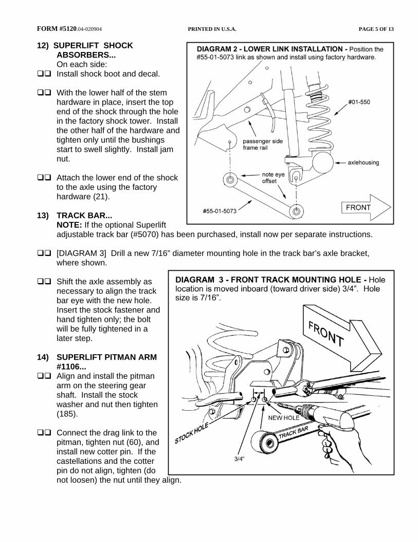
[DIAGRAM 2] On each side, install the 5073 lower links using the factory hardware. Note the eye offset: be sure to install each link as shown using the factory hardware. The cam bolts install at the axle with the nut side facing inboard. Only hand tighten the cam bolts; they, along with the links’ rear eye bolts, are fully tightened in a later step.
FORM #5120.04-020904 PRINTED IN U.S.A. PAGE 5 OF 13
12) SUPERLIFT SHOCK ABSORBERS...
On each side: Install shock boot and decal.
With the lower half of the stem
hardware in place, insert the top end of the shock through the hole in the factory shock tower. Install the other half of the hardware and tighten only until the bushings start to swell slightly. Install jam nut.
Attach the lower end of the shock
to the axle using the factory hardware (21).
13) TRACK BAR... NOTE: If the optional Superlift
adjustable track bar (#5070) has been purchased, install now per separate instructions.
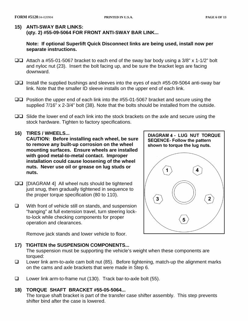
[DIAGRAM 3] Drill a new 7/16” diameter mounting hole in the track bar’s axle bracket, where shown.
Shift the axle assembly as
necessary to align the track bar eye with the new hole. Insert the stock fastener and hand tighten only; the bolt will be fully tightened in a later step.
14) SUPERLIFT PITMAN ARM
#1106... Align and install the pitman
arm on the steering gear shaft. Install the stock washer and nut then tighten (185).
Connect the drag link to the
pitman, tighten nut (60), and install new cotter pin. If the castellations and the cotter pin do not align, tighten (do not loosen) the nut until they align.
FORM #5120.04-020904 PRINTED IN U.S.A. PAGE 6 OF 13
15) ANTI-SWAY BAR LINKS: (qty. 2) #55-09-5064 FOR FRONT ANTI-SWAY BAR LINK... Note: If optional Superlift Quick Disconnect links are being used, install now per
separate instructions.
Attach a #55-01-5067 bracket to each end of the sway bar body using a 3/8” x 1-1/2” bolt and nyloc nut (23). Insert the bolt facing up, and be sure the bracket legs are facing downward.
Install the supplied bushings and sleeves into the eyes of each #55-09-5064 anti-sway bar
link. Note that the smaller ID sleeve installs on the upper end of each link.
Position the upper end of each link into the #55-01-5067 bracket and secure using the supplied 7/16” x 2-3/4” bolt (38). Note that the bolts should be installed from the outside.
Slide the lower end of each link into the stock brackets on the axle and secure using the
stock hardware. Tighten to factory specifications. 16) TIRES / WHEELS... CAUTION: Before installing each wheel, be sure
to remove any built-up corrosion on the wheel mounting surfaces. Ensure wheels are installed with good metal-to-metal contact. Improper installation could cause loosening of the wheel nuts. Never use oil or grease on lug studs or nuts.
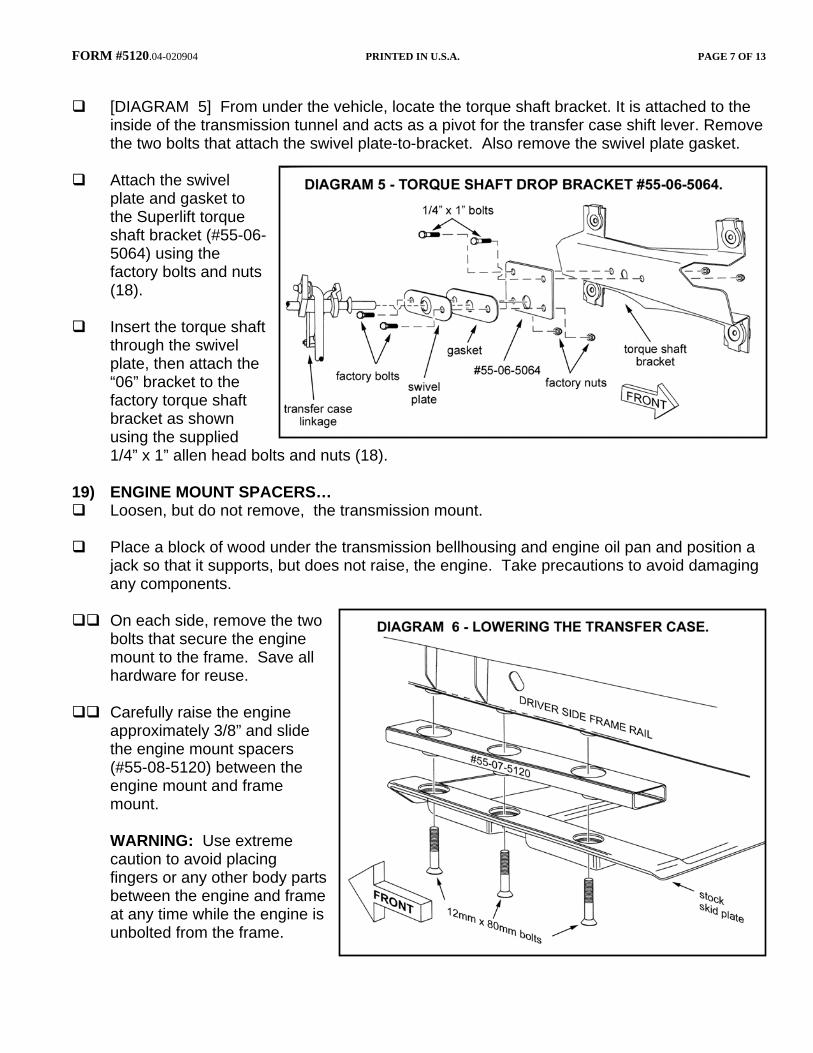
[DIAGRAM 4] All wheel nuts should be tightened
just snug, then gradually tightened in sequence to the proper torque specification (80 to 110).
With front of vehicle still on stands, and suspension
“hanging” at full extension travel, turn steering lock-to-lock while checking components for proper operation and clearances.
Remove jack stands and lower vehicle to floor. 17) TIGHTEN the SUSPENSION COMPONENTS... The suspension must be supporting the vehicle’s weight when these components are
torqued: Lower link arm-to-axle cam bolt nut (85). Before tightening, match-up the alignment marks
on the cams and axle brackets that were made in Step 6.
Lower link arm-to-frame nut (130). Track bar-to-axle bolt (55). 18) TORQUE SHAFT BRACKET #55-05-5064... The torque shaft bracket is part of the transfer case shifter assembly. This step prevents
shifter bind after the case is lowered.
FORM #5120.04-020904 PRINTED IN U.S.A. PAGE 7 OF 13
[DIAGRAM 5] From under the vehicle, locate the torque shaft bracket. It is attached to the
inside of the transmission tunnel and acts as a pivot for the transfer case shift lever. Remove the two bolts that attach the swivel plate-to-bracket. Also remove the swivel plate gasket.
Attach the swivel
plate and gasket to the Superlift torque shaft bracket (#55-06-5064) using the factory bolts and nuts (18).
Insert the torque shaft
through the swivel plate, then attach the “06” bracket to the factory torque shaft bracket as shown using the supplied 1/4” x 1” allen head bolts and nuts (18).
19) ENGINE MOUNT SPACERS…
Loosen, but do not remove, the transmission mount.
Place a block of wood under the transmission bellhousing and engine oil pan and position a jack so that it supports, but does not raise, the engine. Take precautions to avoid damaging any components.
On each side, remove the two
bolts that secure the engine mount to the frame. Save all hardware for reuse.
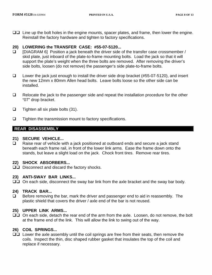
Carefully raise the engine
approximately 3/8” and slide the engine mount spacers (#55-08-5120) between the engine mount and frame mount.
WARNING: Use extreme
caution to avoid placing fingers or any other body parts between the engine and frame at any time while the engine is unbolted from the frame.
FORM #5120.04-020904 PRINTED IN U.S.A. PAGE 8 OF 13
Line up the bolt holes in the engine mounts, spacer plates, and frame, then lower the engine. Reinstall the factory hardware and tighten to factory specifications.
20) LOWERING the TRANSFER CASE: #55-07-5120...
[DIAGRAM 6] Position a jack beneath the driver side of the transfer case crossmember / skid plate, just inboard of the plate-to-frame mounting bolts. Load the jack so that it will support the plate’s weight when the three bolts are removed. After removing the driver’s side bolts, loosen (do not remove) the passenger’s side plate-to-frame bolts.
Lower the jack just enough to install the driver side drop bracket (#55-07-5120), and insert
the new 12mm x 80mm Allen head bolts. Leave bolts loose so the other side can be installed.
Relocate the jack to the passenger side and repeat the installation procedure for the other
“07” drop bracket.
Tighten all six plate bolts (31).
Tighten the transmission mount to factory specifications. REAR DISASSEMBLY
21) SECURE VEHICLE...
Raise rear of vehicle with a jack positioned at outboard ends and secure a jack stand beneath each frame rail, in front of the lower link arms. Ease the frame down onto the stands, but leave a slight load on the jack. Chock front tires. Remove rear tires.
22) SHOCK ABSORBERS...
Disconnect and discard the factory shocks. 23) ANTI-SWAY BAR LINKS...
On each side, disconnect the sway bar link from the axle bracket and the sway bar body. 24) TRACK BAR...
Before removing the bar, mark the driver and passenger end to aid in reassembly. The plastic shield that covers the driver / axle end of the bar is not reused.
25) UPPER LINK ARMS...
On each side, detach the rear end of the arm from the axle. Loosen, do not remove, the bolt at the frame end of the link. This will allow the link to swing out of the way.
26) COIL SPRINGS...
Lower the axle assembly until the coil springs are free from their seats, then remove the coils. Inspect the thin, disc shaped rubber gasket that insulates the top of the coil and replace if necessary.
FORM #5120.04-020904 PRINTED IN U.S.A. PAGE 9 OF 13
REAR ASSEMBLY
27) CAM BOLT SLOTS...
On each side, look at the axle bracket that captures the upper link’s rear eye. Knockout the perforated plug that makes the round hole a slotted hole. If necessary, dress the slot with a file and paint the exposed metal.
28) UPPER LINK ARMS...
On each side, use Superlift cam bolt assembly #1-03-5062 to reattach the link to the axle. Install the bolts from the inside so they point outward. Rotate the cams so that the tall side of the lobes point straight up (12 O’clock position). Do not fully tighten; the bolts are torqued in a later step.
On each side, attach the link’s front eye to the frame. Do not fully tighten; the bolts are
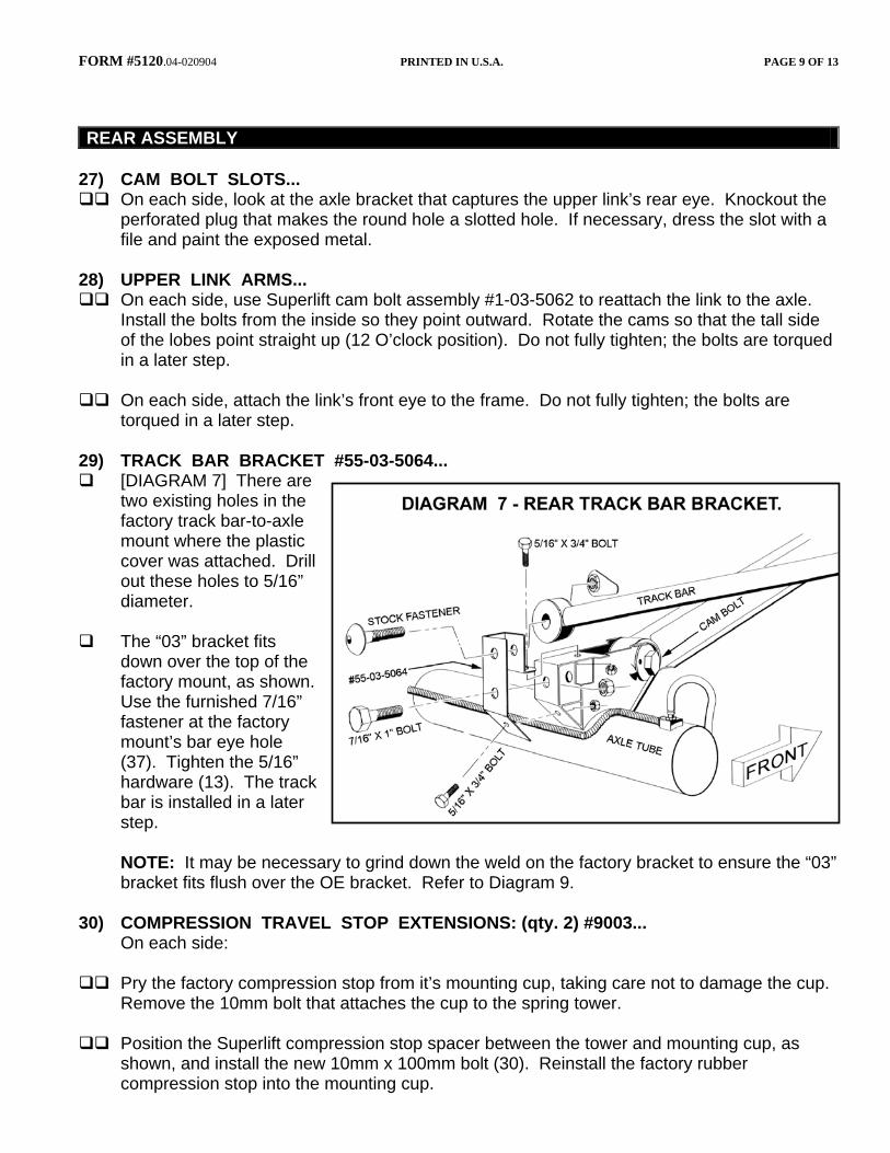
torqued in a later step. 29) TRACK BAR BRACKET #55-03-5064... [DIAGRAM 7] There are
two existing holes in the factory track bar-to-axle mount where the plastic cover was attached. Drill out these holes to 5/16” diameter.
The “03” bracket fits
down over the top of the factory mount, as shown. Use the furnished 7/16” fastener at the factory mount’s bar eye hole (37). Tighten the 5/16” hardware (13). The track bar is installed in a later step.
NOTE: It may be necessary to grind down the weld on the factory bracket to ensure the “03”
bracket fits flush over the OE bracket. Refer to Diagram 9. 30) COMPRESSION TRAVEL STOP EXTENSIONS: (qty. 2) #9003... On each side:
Pry the factory compression stop from it’s mounting cup, taking care not to damage the cup. Remove the 10mm bolt that attaches the cup to the spring tower.
Position the Superlift compression stop spacer between the tower and mounting cup, as
shown, and install the new 10mm x 100mm bolt (30). Reinstall the factory rubber compression stop into the mounting cup.
FORM #5120.04-020904 PRINTED IN U.S.A. PAGE 10 OF 13
31) SUPERLIFT COIL SPRINGS #551... On each side, position the coil spring on the axle pad. It may be necessary to loosen the
lower links’ front and rear eye bolts so the axle can drop enough for coil installation.
Raise the axle until the springs seat in their upper mounts. Do not forget the stock coil gaskets for the top of the coils.
After both coils are in place, jack up the axle assembly until the springs are seated. Be sure
the frame rails remain on the jack stands. 32) TRACK BAR...
Install the track bar. Reuse the factory fasteners at both ends. Hand tighten only; both bolts are fully tightened in a later step. It may be necessary to pry the axle assembly over in order to connect the bar.
33) ANTI-SWAY BAR LINKS: (qty. 2) #55-10-5064 REAR ANTI-SWAY BAR LINK... Note: If optional Superlift Quick Disconnect Links are being used, install now per
separate instructions.
Install the supplied bushings and sleeves in the eyes of each #55-10-5064 anti-sway bar link.
Position the ends of each link in the stock brackets on the axle and the frame, then secure using the stock hardware. Tighten to factory specifications.
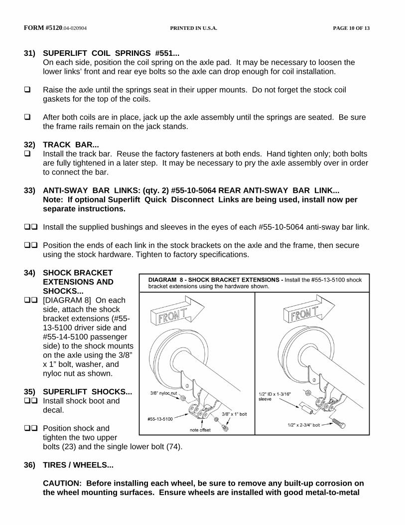
34) SHOCK BRACKET
EXTENSIONS AND SHOCKS...
[DIAGRAM 8] On each side, attach the shock bracket extensions (#55-13-5100 driver side and #55-14-5100 passenger side) to the shock mounts on the axle using the 3/8” x 1” bolt, washer, and nyloc nut as shown.
35) SUPERLIFT SHOCKS...
Install shock boot and decal.
Position shock and
tighten the two upper bolts (23) and the single lower bolt (74).
36) TIRES / WHEELS... CAUTION: Before installing each wheel, be sure to remove any built-up corrosion on
the wheel mounting surfaces. Ensure wheels are installed with good metal-to-metal
FORM #5120.04-020904 PRINTED IN U.S.A. PAGE 11 OF 13
contact. Improper installation could cause loosening of the wheel nuts. Never use oil or grease on lug studs or nuts.
[DIAGRAM 4] All wheel nuts should be tightened just snug, the gradually tightened in
sequence to the proper torque specification (80 to 110). With front of vehicle still on stands, and suspension “hanging” at full extension travel, check
all components for proper operation and clearances. Remove jack stands and lower vehicle to floor. 37) TIGHTEN the SUSPENSION COMPONENTS... The suspension must be supporting the vehicle’s weight when these components are
torqued:
Track bar, both ends (74) Lower link arm, both ends (130)
Upper link arm, frame end (55)
Upper link arm, axle (cam bolt) end (85)
NOTE: Prior to torquing the cam bolts, again use the inclinometer to take a rear driveshaft
angle reading, and compare this to the reading taken in Step 1. Rotate the cam bolts as needed to get shaft angle as close to the Step 1 reading as possible. This will minimize or eliminate shaft vibration due to excessive angle. The 12 O’clock position that the cams were initially adjusted to in Step 28 yields the least amount of angle. It is important that both cams are adjusted identically. To reduce vibration under acceleration, rotate the cams to move the pinion bearing downward. To reduce vibration under deceleration, rotate the cams to move the pinion bearing upward.
38) HEADLIGHTS...
Readjust headlights to factory setting. 39) FINAL OVERALL INSPECTION and TORQUE CHECK...
Perform a front-to-rear inspection. With the suspension supporting vehicle weight, cycle steering lock-to-lock and inspect steering, suspension, driveline, and brake systems for proper operation, tightness, and adequate clearances. Retorque all fasteners.
40) TRANSMISSION SHIFTER MODIFICATION… This step is only necessary if the vehicle exhibits problems shifting after the lift installation is
complete.
Test drive the vehicle and shift through all gears. If it is difficult to shift into (or the transmission jumps out of) Second, Fourth, or Reverse, the shifter is likely hitting the edge of the transmission tunnel due to the transfer case drop and will need to be modified slightly.
FORM #5120.04-020904 PRINTED IN U.S.A. PAGE 12 OF 13
Set the parking brake on the vehicle and put the transmission in neutral. Remove the shift knob and upper shifter boot. Shift the transfer case lever into neutral and remove the console, lower shift boot, and dust boot.
Remove the shifter from the
transmission following the procedure found in the factory service manual.
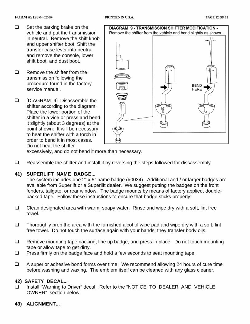
[DIAGRAM 9] Disassemble the
shifter according to the diagram. Place the lower portion of the shifter in a vice or press and bend it slightly (about 3 degrees) at the point shown. It will be necessary to heat the shifter with a torch in order to bend it in most cases. Do not heat the shifter excessively, and do not bend it more than necessary.
Reassemble the shifter and install it by reversing the steps followed for dissassembly.
41) SUPERLIFT NAME BADGE... The system includes one 2” x 5” name badge (#0034). Additional and / or larger badges are
available from Superlift or a Superlift dealer. We suggest putting the badges on the front fenders, tailgate, or rear window. The badge mounts by means of factory applied, double-backed tape. Follow these instructions to ensure that badge sticks properly:
Clean designated area with warm, soapy water. Rinse and wipe dry with a soft, lint free
towel. Thoroughly prep the area with the furnished alcohol wipe pad and wipe dry with a soft, lint
free towel. Do not touch the surface again with your hands; they transfer body oils.
Remove mounting tape backing, line up badge, and press in place. Do not touch mounting tape or allow tape to get dirty.
Press firmly on the badge face and hold a few seconds to seat mounting tape.
A superior adhesive bond forms over time. We recommend allowing 24 hours of cure time before washing and waxing. The emblem itself can be cleaned with any glass cleaner.
42) SAFETY DECAL...
Install “Warning to Driver” decal. Refer to the “NOTICE TO DEALER AND VEHICLE OWNER” section below.
43) ALIGNMENT...
FORM #5120.04-020904 PRINTED IN U.S.A. PAGE 13 OF 13
Realign vehicle to factory specifications. IMPORTANT PRODUCT USE INFORMATION As a general rule, the taller a vehicle is, the easier it will roll over. Offset, as much as possible, what is lost in roll over resistance by increasing tire track width. In other words, go “wide” as you go “tall”. Many sportsmen remove their mud tires after winter / hunting season and install ones more appropriate for street driving; always use as wide a tire and wheel combination as possible to enhance vehicle stability.
We strongly recommend, because of roll over possibility, that the vehicle be equipped with a functional roll bar and cage system. Seat belts and shoulder harnesses should be worn at all times. Avoid situations where a side rollover may occur.
Generally, braking performances and capabilities are decreased when significantly larger / heavier tires and wheels are used. Take this into consideration while driving.
Do not add, alter, or fabricate any factory or aftermarket parts to increase vehicle height over the intended height of the Superlift product purchased. Mixing component brands is not recommended.
Most states have some type of law limiting vehicle height. The amount of lift allowed, and how the lift may be achieved, varies greatly. Several states offer exemptions for farm or commercially registered vehicles. It is the owner’s responsibility to check state and local laws to ensure that their vehicle will be in compliance.
Superlift makes no claims regarding lifting devices and excludes any and all implied claims. Superlift will not be responsible for any altered product or any improper installation or use of our products.
We will be happy to answer any questions concerning the design, function, and correct use of our products.
IMPORTANT MAINTENANCE INFORMATION It is the ultimate buyer’s responsibility to have all bolts / nuts checked for tightness after the first 100 miles and then every 1000 miles. The steering, suspension and driveline systems, along with wheel alignment should be inspected by a qualified professional mechanic at least every 3000 miles.
NOTICE TO DEALER AND VEHICLE OWNER Any vehicle equipped with a Superlift lifting device must have the enclosed “Warning to Driver” decal installed on the inside of the windshield or on the vehicle’s dash, within driver’s view. The “Warning to Driver” decal is to act as a constant safety reminder for whoever may be operating the vehicle. The WARRANTY IS VOID unless this decal is in place. INSTALLING DEALER... It is your responsibility to install warning decal and forward these installation instructions to the vehicle owner for review of warnings, product use and maintenance information. Replacement warning decals are available free upon request. These instructions are to be kept with the vehicle registration papers and owners manual for the service life of the vehicle.
SUPERLIFT LIMITED LIFETIME WARRANTY Suspension products bearing the Superlift (LKI Ent.) name are warranted for as long as the original purchaser owns the vehicle that the LKI product was originally installed on. This warranty is non-transferable. Warranty covers only the product, no labor, time loss, or freight incurred. Any product that has been abused, altered, incorrectly installed, or used in competition is not covered. Product finish, spring bushings, Polyurethane products, and normal wear is not covered. The LKI product is subject to replacement or repair. No other warranties are expressed or implied. An authorized Superlift dealer must inspect the part in question and confirm that the “Warning to Driver” decal is properly displayed. A copy of the sales invoice is required for warranty consideration.