SUPERHEATER IN THE FURNACE FOR INCREASING …/media/Downloads/Conference_papers_-_WTE/...SUPERHEATER...
12
Proceedings Venice 2014, Fifth International Symposium on Energy from Biomass and Waste San Servolo, Venice, Italy; 17 - 20 November 2014 2014 by CISA Publisher, Italy SUPERHEATER IN THE FURNACE FOR INCREASING THE EFFICIENCY T. NORMAN, L. MIKKELSEN AND O. HEDEGAARD MADSEN Babcock & Wilcox Vølund A/S, Falkevej 2, DK-6705 Esbjerg Ø, Denmark SUMMARY: Babcock & Wilcox Vølund have recently developed a new technology and obtained a world patent for it. The basic idea is to improve the electrical efficiency by increasing the steam parameters. The steam temperature in particular can be increased without increasing the superheater corrosion. The new concept can be fully integrated into the boiler, and the waste-fired power plant then has the same external layout as a classical waste-to-energy plant. The new superheater system is currently being tested at a Danish power plant. To obtain high steam temperatures, superheaters are fitted into the furnace above the last part of the grate where flue gas with very high energy and a low content of corrosive elements is available. The heat rate is 20 - 30 kW/m 2 , which is five to ten times the rates realised in standard convection superheaters. The results are a promising low corrosion level and a material forming a thin layer of alumina (-Al2O3) show very promising corrosion level at high material and flue gas temperature. 1. INTRODUCTION The main problem associated with increasing the steam parameters are corrosion and fouling in the boiler. The fouling can be handled by boiler cleaning equipment, whereas corrosion is destructive to the boiler and plant operation and remains a difficult problem. The current requirements for plant availability are up to 8300 hours per year. The operational hours are one of the most important factors for the plant owner, because they are the basis of the annual income and decide whether the plant can be run profitably. This results in a very conservative business where investors tend to choose a well-proven technology in order to minimise the financial risk. The lifetime of the superheater tubes is a critical parameter. New materials, on-line boiler cleaning and design tools such as CFD modelling have improved the steam data and thus boosted the electrical efficiency. A number of ways are available to increase the efficiency of a plant. This paper focuses on increasing the steam parameters as cost-effectively as possible. Steam values of 55 bar and 425°C are common and well-established inlet parameters for steam turbines in existing MSW plants. Corrosion on heating surfaces in direct contact with flue gases is low in MSW boilers operated with these steam parameters. Higher live steam temperature levels increase the corrosion risks in the superheater sections. For higher steam temperatures, the superheater design is increasingly constrained by the risk of corrosion. High live steam pressure levels lead to higher temperature levels in the radiation part of the boiler, since at higher pressures the water evaporates at higher
Transcript of SUPERHEATER IN THE FURNACE FOR INCREASING …/media/Downloads/Conference_papers_-_WTE/...SUPERHEATER...

Proceedings Venice 2014, Fifth International Symposium on Energy from Biomass and Waste
San Servolo, Venice, Italy; 17 - 20 November 2014
2014 by CISA Publisher, Italy
SUPERHEATER IN THE FURNACE FOR
INCREASING THE EFFICIENCY
T. NORMAN, L. MIKKELSEN AND O. HEDEGAARD MADSEN
Babcock & Wilcox Vølund A/S, Falkevej 2, DK-6705 Esbjerg Ø, Denmark
SUMMARY: Babcock & Wilcox Vølund have recently developed a new technology and obtained a
world patent for it. The basic idea is to improve the electrical efficiency by increasing the steam
parameters. The steam temperature in particular can be increased without increasing the superheater
corrosion. The new concept can be fully integrated into the boiler, and the waste-fired power plant
then has the same external layout as a classical waste-to-energy plant. The new superheater system
is currently being tested at a Danish power plant. To obtain high steam temperatures, superheaters
are fitted into the furnace above the last part of the grate where flue gas with very high energy and a
low content of corrosive elements is available. The heat rate is 20 - 30 kW/m2, which is five to ten
times the rates realised in standard convection superheaters. The results are a promising low
corrosion level and a material forming a thin layer of alumina (-Al2O3) show very promising
corrosion level at high material and flue gas temperature.
1. INTRODUCTION
The main problem associated with increasing the steam parameters are corrosion and fouling in the
boiler. The fouling can be handled by boiler cleaning equipment, whereas corrosion is destructive to
the boiler and plant operation and remains a difficult problem.
The current requirements for plant availability are up to 8300 hours per year. The operational
hours are one of the most important factors for the plant owner, because they are the basis of the
annual income and decide whether the plant can be run profitably. This results in a very
conservative business where investors tend to choose a well-proven technology in order to minimise
the financial risk.
The lifetime of the superheater tubes is a critical parameter. New materials, on-line boiler
cleaning and design tools such as CFD modelling have improved the steam data and thus boosted
the electrical efficiency.
A number of ways are available to increase the efficiency of a plant. This paper focuses on
increasing the steam parameters as cost-effectively as possible. Steam values of 55 bar and 425°C
are common and well-established inlet parameters for steam turbines in existing MSW plants.
Corrosion on heating surfaces in direct contact with flue gases is low in MSW boilers operated
with these steam parameters. Higher live steam temperature levels increase the corrosion risks in
the superheater sections. For higher steam temperatures, the superheater design is increasingly
constrained by the risk of corrosion. High live steam pressure levels lead to higher temperature
levels in the radiation part of the boiler, since at higher pressures the water evaporates at higher

Venice 2014, Fifth International Symposium on Energy from Biomass and Waste
temperatures. An increase of live steam pressure consequently leads to a higher risk of corrosion in
the radiation part of the boiler. Corrosion is mainly due to high temperature chlorine attack, either
through gaseous species or by chloride particles deposited on the boiler walls.
The increase in electrical efficiency achieved by increasing the steam temperature is almost
constant 0.5% / 25˚C. Consequently the aim should be to get the temperature as high as possible.
Nevertheless, the risk of corrosion in the superheaters is limiting the temperature and this limit is
440˚C for current technology in view of the European market standards for lifetime guarantees of
five years for the superheaters.
A new superheater system has consequently been developed. Flue gas measurements conducted
on a waste-to-energy plant in Denmark indicated that the flue gas is less corrosive over the last part
of the grate (Bøjer et al., 2008). This is in accordance with the results obtained from CFD
modelling. Superheaters may therefore be applied in the furnace above the last part of the grate to
obtain higher steam temperatures in the range of 480 – 520˚C. The results from a Danish test
facility are reported in this paper. They show a promising level of heat transfer and a low corrosion
level as expected from the theoretical analysis carried out prior to the test.
2. INCREASING THE EFFICIENCY OF A MSW POWER PLANT
2.1 Ways of increasing the efficiency
Babcock & Wilcox Vølund A/S trust that waste-to-energy is one of the best technologies for
converting non-recyclable waste into energy and new raw materials. The company wants to build
the best plants for this purpose, and Babcock & Wilcox Vølund A/S consequently aims to build
plants with the highest possible steam parameters.
A number of methods can be used to increase the efficiency of a plant. The general parameters
influencing the boiler and electrical efficiencies are listed in Table 1 below:
Table 1. Ways of increasing the efficiency
Boiler efficiency Electrical efficiency
Reduction of excess air High steam parameters (p, T)
Low flue-gas temperature at boiler outlet Steam reheating
Low moisture content in fuel High feedwater temperature
Oxy-fuel combustion Stepwise preheating of condensate and feedwater
External economiser after filter Preheating combustion air with steam bleed from
the turbine
Integration with other power generators such as a
gas turbine
Air preheating with a flue-gas heat exchanger
(enamel-coated)
Reduction of auxiliary consumption
Stability of steam production
Every effort is made to pursue all these methods wherever possible. In regions where only power
production is relevant, high steam parameters are very important. However, increasing the steam
parameters also increases the risk of corrosion. Waste is one of the most challenging fuels to burn,
giving rise to many different problems, of which corrosion is one. One of the most important factors

Venice 2014, Fifth International Symposium on Energy from Biomass and Waste
here is the composition of the waste. Waste from a particular geographical region or a specific type
of waste will lead to different corrosion problems. Nevertheless, the two main parameters affecting
high-temperature corrosion in waste incinerators are the temperatures of the metal tubes and of the
flue gas.
Ways of increasing the steam temperature:
Refractory-covered platen superheater in second pass (monolithic SiC)
Hanging superheater in first pass
Superheater in furnace (SteamBoost™)
Superheater panel in furnace
Final superheater in front of the convection pass (extra evaporator to even out the flow)
External superheater (fired with low corrosive fuel).
2.2 Hypotheses underlying a superheater in the furnace
Waste incineration is among the most complex of combustion processes. The processes
occurring in a burning fuel bed include drying, ignition, pyrolysis and gasification as well as solid
and gas combustion. The release of the volatile elements Cl, Na, K, Pb, Zn and S to the flue gas and
the aerosol formation from them is of special interest. These elements are present at high
concentrations in ash deposit layers, where they may form various sulphate and chloride salts
capable of inducing high corrosion rates. Deposits with a high Cl content in particular lead to high
corrosion of boiler tubes.
Figure 1 is a simplified illustration of the various processes occurring in a fuel bed on a grate.
Pyrolysis gases are released in the ignition zone due to rapid heating of the top waste layer before
combustion starts. A large zone of the grate is sub-stoichiometric and results in the formation of
gasification products. Thus, pure gas-phase combustion is achieved directly above the waste layer
where a relatively large part of the total energy is released from the waste. The burnout of these
gases, soot and particles leaving the bed forms the radiant flames above the grate.
The release of chlorides from the fuel into the flue gas depends on the properties of the chlorine-
bearing components and on the firing conditions. The overall distribution is illustrated in
Figure 1, where the ignition, pyrolysis/devolatilisation and burning zones are located in the first
part of the grate and fuel bed. The major parts of the corrosive species are released in the first part
of the combustion grate and hence in the front of the furnace. The rear parts of the grate are
characterised by burnout of a relatively clean char, thereby releasing relatively clean combustion
products which are much less corrosive. This phenomenon can be utilised to split up the flue gases
from the grate into two or more fractions, one of which exhibits a high heat flux and a low chlorine
concentration. This fraction could then be used in a high-temperature superheater to increase the
steam temperature and thereby the electrical efficiency of waste-fired power plants. The concept is
named SteamBoost™ (Bøjer et al., 2008).
The history behind this concept is summarised below:
2006 Concept developed in cooperation between BWV and DTU.
2007 Patent filed in cooperation between BWV and DTU.
2007 Patent transferred to sole ownership of BWV.
2007 Flue-gas measurements on Danish plant to test the concept. Concept development with
CFD.
2012 Test facility established in a Danish plant (AffaldPlus).
2013 Test upgraded to a steam temperature of 440°C.
From September 2014, it is planned to operate the test facility at 480°C.
Venice 2014, Fifth International Symposium on Energy from Biomass and Waste
Figure 1. The SteamboostTM concept
2.2.1 Testing the concept
The CHEC Research Centre at the Department of Chemical and Biochemical Engineering at the
Technical University of Denmark carried out a series of full-scale experiments in order to verify the
Cl release profile in a typical waste-fired power plant.
The objective of the study was to measure a concentration profile of the elements Cl, Na, K, Zn,
Pb and S as a function of the location on the grate in a waste-to-energy boiler. A heat-flux and
chlorine-release profile along the grate provides information on the location at which heat is
released with the lowest concentrations of corrosion-promoting species in the flue gas. This tests the
basic idea of separating the flue gas from the grate into two or more fractions, with one fraction
having a relatively high heat flux and low chlorine concentration.
Measurement of the concentration and location of the release of Cl, Na, K, Pb, Zn and S from the
grate, combined with information on the magnitude and location of the heat flux from the grate, can
reveal the region of the flue gas with a high heat flux but low concentrations of corrosive elements.
Measurements were conducted at Vestforbrænding Unit 5 - a waste-fired CHP plant in
Copenhagen, Denmark. The plant was commissioned in 1998 and can process up to 30 tonnes per
hour. The waste is burned on a forward-acting grate with a width of 9.75 m and a length of 13.1 m,
comprising a total of 18 zones. Each zone has individually controlled primary-air and grate speeds.
The location of the measuring positions (1-6) relative to the grate is shown in Figure 2. The
measurements were performed by inserting a suction probe into the designated ports 1, 2, 3, 4 and 5
(Bøjer et al., 2007 and Bøjer et al., 2008).

Venice 2014, Fifth International Symposium on Energy from Biomass and Waste
Figure 2. The furnace, grate and position of measuring ports at Vestforbrænding, Unit 5
Figure 3. Measured chlorine release (Bøjer et al., 2007)
Figure 4. Measured alkali release (Bøjer et al., 2007)

Venice 2014, Fifth International Symposium on Energy from Biomass and Waste
3. TEST FACILITY WITH SUPERHEATER IN THE FURNACE
The objective of the test facility is to determine the heat transfer rates that can be used for design
purposes and to implement corrosion-testing of various materials in the superheater at high
temperatures. The test should clarify which materials are best suited for a SteamBoost™
superheater. The project will also clarify the lifetime of this superheater.
3.1 Description of the installation
The steam is taken as a partial stream of 1-2% from the inlet flow to the last superheater (SH3)
which increases the temperature of the normal steam flow of the plant from 370 to 400°C.
However, the temperature of the steam at the inlet to the test superheater is only approximately
340°C because of an unexpected high heat loss from the pipeline from SH3 down to the test loop
located at the back wall of the furnace.
The first phase of the test was consequently carried out at a relatively low steam temperature in
order to minimise corrosion. Nevertheless, the performance of the superheater could still be tested
and analysed. After one year’s operation at this low temperature, the test superheater was upgraded
to the solution shown in Figure 6 with four tube loops instead of only one. When the steam flows
through the three red tubes shown in Figure 6, it is heated from 340 to 420°C, resulting in an outlet
temperature from the last loop in the test superheater of 440°C.
The installation of the test facility and the tests carried out so far were fully financed by Babcock
& Wilcox Vølund A/S. This was possible thanks to a very close cooperation with AffaldPlus. The
plant staff has been very flexible with respect to problems relating to how this kind of test facility
can be integrated into a commercially operated plant.
Figure 5. Pipes and valves at the test facility

Venice 2014, Fifth International Symposium on Energy from Biomass and Waste
Figure 6. CAD drawing of the superheater
Figure 7. Overview of superheater installation
To ensure that the rear end of the furnace is “clean” and not contaminated by recirculation zones
drawing corrosive gases from the front, a flow of air in the opposite direction is introduced through
a large number of small nozzles in the back wall as shown in Figure 8.
The flow creates an air barrier which eliminates the recirculation zone. The CFD results in
Figure 7 show that the concentration of corrosive species in the area where the superheater is placed
is very low. The calculation shows that the concentration of the corrosive species can be reduced by
75% with this new SteamBoost™ concept (Madsen and Sødring, 2011).
Venice 2014, Fifth International Symposium on Energy from Biomass and Waste
Figure 8. Flow pattern and air nozzles in back wall
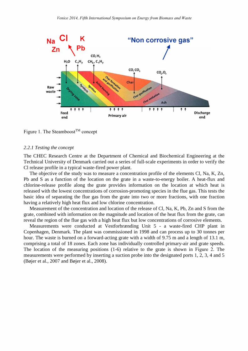
3.2 Operation
The basic operation of the test facility is to extract 1-2% of the steam produced from the plant and
heat it further in the superheater in the furnace to 440 – 480°C. A number of pipes and valves are
needed to make this possible, as can be seen in Figure 5 and Figure 9. A safety cooling system
based on compressed air also had to be implemented: when this system is in operation, the steam
flow is cut off from the test superheater, which is then cooled by a large air flow instead.
The safety cooling system is used when the heat transfer to the test superheater is too large and
consequently generating too high material temperatures. Secondly, maintenance work can then be
carried out on the test superheater system without affecting normal operation of the plant.
Figure 9. Screen dump from PLC during operation

Venice 2014, Fifth International Symposium on Energy from Biomass and Waste
4. RESULTS AND DISCUSSION
4.1 Performance
A test campaign was run to determine the performance of the test superheater with respect to heat
transfer. A large number of different settings of the combustion system were tested. The campaign
showed that the distribution of the primary air under the grate and the ratio of the primary to
secondary air has a decisive effect on the performance. The final setting produces a suitable flame
position and a highly intense flame.
Analysis of the operating data showed that the heat input to the superheater could be kept above
30 kW/m2 by maintaining a high velocity through the nozzle in the front ceiling combined with a
reduced amount of primary air, so that the excess air was held at a level of 0.5 – 0.6.
Figure 10. Heat input to superheater combined with velocity of secondary air. The red curve shows
the velocity of the air entering the furnace through the front ceiling of the furnace. The
blue curve shows the difference in the enthalpy of the steam at the inlet and outlet of the
test superheater.
During the next test phase, a number of tests will be carried out with corrosion and fouling
probes to obtain detailed information about the corrosion potential of the flue gas while optimising
the combustion air supply and the control system. The aim is to minimise corrosion and maximise
the heat transfer.
4.2 Corrosion
The test superheater was installed in 2012 during the revision of the plant and was tested for a year
with steam temperatures in the range of 350-370°C. The corrosion test showed interesting results

Venice 2014, Fifth International Symposium on Energy from Biomass and Waste
despite the first phase of the test being carried out at a relatively low steam temperature with respect
to corrosion. In the second test phase, the last superheater loop was operated with an inlet
temperature of about 420°C while the outlet temperature from the loop was about 440°C. These
conditions prevailed for the past nine months during which the corrosion results were reported.
The measured corrosion of the various materials is listed in Table 2 in terms of material loss. The
tube thicknesses were measured mechanically with an accuracy of approximately ±0.1 mm.
Table 2. Measured corrosion after nine months of operation
Test phase 1 (350 °C) Test phase 2 (440 °C)
Material Average loss (mm/year) Average loss (mm/year)
16Mo3 0.8
13CrMo4-5 2.3
Haynes 214 (alumina) 0.0 0.3
Esshete 1250 1.1 1.6
Sanicro 25 0.9 1.5
Inconel 625 overlay 0.5 1.3
Inconel 686 overlay 0.6 1.1
Haynes 214 overlay 0.8 0.9
Haynes G35 overlay 0.4 1.6 (greatly increased corrosion)
Figure 11. Haynes 214 and 13CrMo4-5. Corrosion after 9 months exposure at approx. 440°C.
The measured corrosion rates at 440°C show that 13CrMo4-5 exhibits the highest corrosion rate,
while the tubes of the overlay welding, the Esshete 1250 and the Sanicro 25, exhibit a medium
corrosion rate, and the Haynes 214 tube has a very low corrosion rate. A general observation is that
the corrosion rate increases with increasing steam temperature.
Low alloyed materials (e.g. 16Mo3 and 13Mo4-5) form an iron oxide during corrosion, whereas
Haynes 214 13CrMo4-5
Venice 2014, Fifth International Symposium on Energy from Biomass and Waste
higher alloyed steels (e.g. Sanicro 25, Esshete 1250, Inconel 686, Inconel 625 and Haynes G35)
form a chromium oxide scale during corrosion. Aluminium-containing alloys (e.g. Haynes 214)
may form a dense protective layer of -Al2O3 (alpha-alumina) during corrosion. Experience has
shown that this layer forms at very high temperatures, and that the oxides offer corrosion protection
in the following order: alpha-alumina > chromium oxide > iron oxide.
Before the Haynes 214 material was installed in the superheater, the material was heat-treated at
1095°C for 45 minutes. This was done in order to initiate the formation of a thin layer of alumina
(-Al2O3). Haynes 214 was also tested as an overlay welding. In this case, no heat treatment was
performed before the installation of the superheater. Nevertheless, it seems to perform well at high
temperatures compared to the other overlay welds. A difference is that Haynes 214 shows a low
relative increase in corrosion when the steam temperature is increased.
No protective alumina layer forms during normal operation, which explains the large differences
in corrosion rate observed for the Haynes 214 tube and the Haynes 214 overlay welding.
As mentioned earlier, a number of tests will be carried out with corrosion and fouling probes in
order to obtain detailed information about the corrosion during the next test phase. The steam
temperature will be increased by an additional 40°C to obtain a temperature level which would
allow an interesting increase in electrical efficiency for a power plant. The next test phase is
planned to run for 18 months.
When the test superheater is upgraded from 440°C to 480°C, the superheater loops will be
replaced by new ones. This will make it possible carry out a more detailed analysis of the corrosion
results going beyond the basic loss measurements reported in this paper.
5. CONCLUSIONS
A new innovative superheater system is currently being developed and tested at a Danish power
plant. To obtain high steam temperatures, superheaters were applied in the furnace above the last
part of the grate where flue gas with very high energy level and low content of corrosive elements is
available. In the first test phase, the steam temperature was relatively low with respect to the
corrosion test. Nevertheless, the performance of the superheater could still be tested and analysed,
and the heat rate was found to be 20 - 30 kW/m2, which is five to ten times the rates realised in
standard convection superheaters. After one year of low-temperature operation, the test superheater
was upgraded to a solution using four tube loops instead of only one, resulting in an outlet
temperature from the test superheater of 440°C. In September 2014, when the test will have been
running for a year at 440°C, it will be upgraded to 480°C. The results show a promising low
corrosion level, as expected from the theoretical analysis carried out prior to the test, and a material
forming a thin layer of alumina (-Al2O3) show very promising corrosion levels at high material
and flue gas temperature.
During the next test phase, a number of tests will be carried out with corrosion and fouling
probes to obtain detailed information about the corrosion potential of the flue gas while optimising
the air supply and combustion control. This will be carried out in order to minimise the corrosion
and maximise the heat transfer.
ACKNOWLEDGEMENTS
The project was originally funded by the PSO Project 59281 and STVF (The Danish Technical
Research Council) and was run in cooperation with the CHEC Research Group at the Department of
Chemical and Biochemical Engineering, The Technical University of Denmark.

Venice 2014, Fifth International Symposium on Energy from Biomass and Waste
AffaldPlus in Næstved, Denmark, gave us access to the plant and permitted us to implement the
superheater system in the furnace. This was crucial for ensuring the feasibility of the project.
REFERENCES
Hedegaard Madsen O.; Next Generation of Waste Fired Power Plants, NAWTEC 15, Miami, USA,
21 – 23 May 2007.
Bøjer M., Arendt Jensen P., Frandsen F., Dam-Johansen K., Hedegaard Madsen O. and Lundtorp
K.; Release of Potentially Corrosive Constituents from the Grate of a Waste-to-Energy Boiler,
IT3’07, May 14–18, 2007, Phoenix, AZ, USA.
PCT/IB2006/053560; BOILER PRODUCING STEAM FROM FLUE GASES UNDER
OPTIMISED CONDITIONS, 2006.
Bøjer M., Arendt Jensen P., Frandsen F., Dam-Johansen K., Hedegaard Madsen O., Lundtorp K.;
Alkali/Chloride release during refuse incineration on a grate: Full-scale experimental findings,
Fuel Processing Technology, vol: 89, issue: 5, pages: 528-539, 2008, Elsevier Science.
Hedegaard Madsen O., Wagner Sødring T.; A New Concept To Improve the Electrical Efficiency
Based on the Combustion Process in the Waste Fuel Bed on a Grate, ISWA 2011, Korea