
SUPERCACITOR MODEL IN PSIM - ENEA · 2016-08-10 · SUPERCACITOR MODEL IN PSIM ... PSIM is a...
21
1 SUPERCACITOR MODEL IN PSIM Workshop on Superapacitors and energy storage Friday 13th May 2016, ENEA - Frascati, Italy Jules FONO POWERSYS
Transcript of SUPERCACITOR MODEL IN PSIM - ENEA · 2016-08-10 · SUPERCACITOR MODEL IN PSIM ... PSIM is a...

1
SUPERCACITOR MODEL IN PSIM
Workshop on Superapacitors and energy storageFriday 13th May 2016, ENEA - Frascati, Italy
Jules FONOPOWERSYS
2
Outline presentation
� POWERSYS overview
� PSIM overview and main functions / capabilities
� PSIM model for Supercapacitor
� Application on automobile hybrid energy storage

POWERSYS: Presentation
� Powersys is a French company providing Solutions for Power Systems Engineering
Simulation.
� Our core business:
� Development and sales of simulation software for power Systems Engineering
� Engineering Studies Services
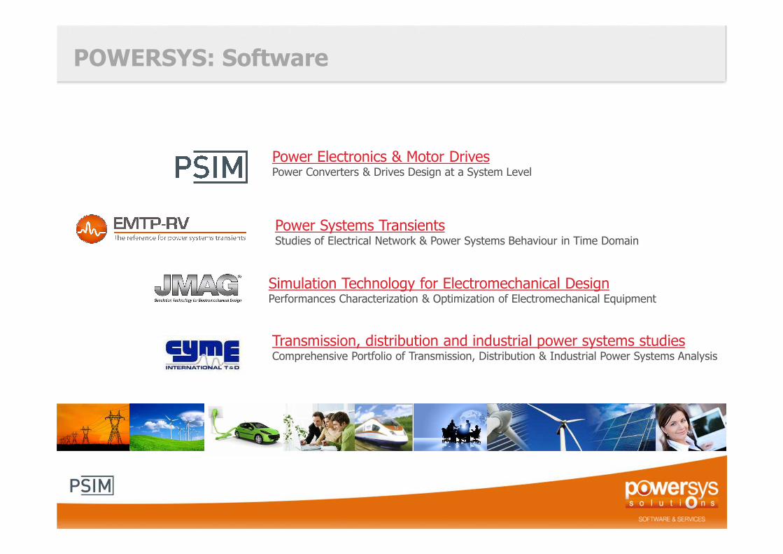
POWERSYS: Software
Power Electronics & Motor DrivesPower Converters & Drives Design at a System Level
Power Systems TransientsStudies of Electrical Network & Power Systems Behaviour in Time Domain
Simulation Technology for Electromechanical DesignPerformances Characterization & Optimization of Electromechanical Equipment
Transmission, distribution and industrial power systems studiesComprehensive Portfolio of Transmission, Distribution & Industrial Power Systems Analysis

11
What is PSIM?
� PSIM is a simulation software specifically designed for power electronics, motor drives and energy conversion applications.
� It is positioned between a device/circuit simulator (such as SPICE) and a system/control simulator (such as Matlab/Simulink).
SPICE Matlab/Simulink
Device and CircuitSimulation
System and ControlSimulation
• Fast• Easy to use• Affordable• Expandable

6
Key features and advantages of PSIM
� User Friendly and very easy to use.
� Fast and robust computation engine.
� Comprehensive power and control libraries.
� Powerful control simulation (op. amp., s-domain, z-domain, C code, or Matlab/Simulink).
� Thermal Module for quick power loss estimation.
� Automatic code generation for hardware implementation.
� Link to 3rd-party software (e.g. Matlab/Simulink, JMAG, MagNet).
� Design Suites to provide power and control solution directly from user specifications.
PSIM model for Supercapacitor
Introduction on Supercacitors:
� Until recently, batteries were the only affordable energy storage system in conventional applications.
� Nowadays, supercapacitors are a sound alternative with high power density, fast recharge and long lifetime (up to 1 million of charge/discharge cycles).
� On the other hand, since the energy density available in supercapacitors is lower than in batteries, the most common application is in hybrid (batteries/supercapacitors) energy storage systems, for example to sustain the load peaks, to reduce the system weight or to extend its lifetime.

PSIM model for Supercapacitor
The PSIM Supercapacitor model is presented below:
- Number of Cells in Series- Number of Cells in Parallel- Capacitance per Cell- Coefficient Kv
- Resistance R1
- Capacitance C1
- Resistance R2
- Capacitance C2
- Resistance R3
- Capacitance C3
- Resistance R4
- Maximum Voltage Vrated
- Initial Voltage

PSIM model for Supercapacitor
To determine the model parameters, we need: � Information from the datasheet.� Experimental measurement of the supercapacitor voltage under a charging and discharging
process.

PSIM model for Supercapacitor
Parameters Kv, R1, and C1 affect the short-term response (in seconds).They are calculated based on the charging current and capacitor voltage at 0, t2 and t3.

PSIM model for Supercapacitor
Parameters R2 and C2 affect the short-to-medium term response (in minutes).They are calculated based on the capacitor voltage at t3, t5, and t6.

PSIM model for Supercapacitor
Parameters R3 and C3 affect the medium-to-long term response (in hundreds of minutes).They are calculated based on the capacitor voltage at t7, t8, and t9.

PSIM model for Supercapacitor
The parameter R4 represents the losses due to capacitor self-discharge.It is calculated from the datasheet using the leakage current.

PSIM model for Supercapacitor
Given the times and voltages as highlighted in the figure below, as well as the charge current, leakage current, and rated voltage, all the model parameters can be calculated using the “Ultracapacitor Model Tool of PSIM”.

PSIM model for Supercapacitor
Example: Maxwell Ultracapacitor 58F 16V (model BMOD0058-E016-B0)
The Maxwell 16V 58F ultracapacitor BMOD0058-E016-B0 is used as an example. From the manufacturer datasheet, the following information is obtained:Rated Capacitance: 58FRated Voltage: 16VLeakage current at 25°C: 25mA
Lab experiment of a single cell capacitor is conducted with a charge current of 35A.
Time (s) Vc (V)0 0.7404488.538 6.4887425.614 15.9667353.86 14.45661051.37 13.82462077.13 13.21163102.88 12.73784128.64 12.3075

PSIM model for Supercapacitor
Example: Maxwell Ultracapacitor 58F 16V (model BMOD0058-E016-B0)
Click on Start Calculating. After less than a minute, the curve fitting error is around 0.36%. We would stop the calculation at this point. The dialog window is shown below.

PSIM model for Supercapacitor
Example: Maxwell Ultracapacitor 58F 16V (model BMOD0058-E016-B0)
A test circuit as shown below is set up to validate the model parameters obtained above.The figures below show the comparison of the simulation result Vc_simu (in red) and the experimental result Vc_exp (in blue).

Automobile hybrid energy storage application
Luc
File
Ud
6-cell UC model Ideal buck/boost converter
Ib
Rs
Rct Cdl
Lbat
Li[NMC]O2electrodedynamicsV Vuc
VVd
Eb*m
700
-100
S1
2.75
dc-link voltage independentpower to load current
Cold cranking load powerexternal file input
4-cell Li[NMC] model Constant Power load model
V VIin V VIout V VIloadV VIbVVbat
Co14800u
� Maxwell Technologies K3400 6-cell module in hybrid combination with Lithium-ion battery model illustrating UC handling load dynamics.
- An ultracapacitor is connected to a buck-boost converter.- The output is connected to a constant-power load.- A Li-Ion battery is connected in parallel to the load.

Automobile hybrid energy storage application
� The load current VIload has sudden changes, going up to 450A, and comingdown to around 300A, and then to 0.
� The bulk of the load current is supplied by the battery VIb.� The difference, which is the sudden change part, is supplied by the
ultracapacitor VIout. � This illustrates ultracapacitor's capability to supply current with high dynamic
change.
0 10 20 30 40 50Time (s)
0
-100
-200
100
200
300
400
500
VIb VIload VIout

Thank you for your attention

Contacts
Corporate web site: www.powersys-solutions.comMore information about PSIM www.powersimtech.com
POWERSYS POWERSYS Inc. POWERSYS POWERSYS
c/o Altios Consulting Pvt Ltd
Cannot be diffused nor copied without the written authorization of POWERSYS21


![Psim Manual[1]](https://static.fdocuments.us/doc/165x107/552735384979595f178b45f9/psim-manual1.jpg)