
SUPER-MOD FOREWORD - Vintage Sno Formula 2 Super Mod.pdf · the vehicle in a warm area. At certain...
37
Transcript of SUPER-MOD FOREWORD - Vintage Sno Formula 2 Super Mod.pdf · the vehicle in a warm area. At certain...


SUPER-MOD FOREWORD
December 1980
The following are trademarks of Bombardier l.irnitee
Bombardier l.imiteeValcourt, Quebec, Canada
This vehicle has been designed for and should be usedon an oval race track only.
The performance of this snowmobile significantly exceeds that of other snowmobiles you may have operated. Therfore, use of this vehicle should be restrictedto experienced snowmobile racers.
•WARNING: The design of this snowmobile differsconsiderably from most other snowmobiles. Main
tenance and adjustment must be performed only by aknowledgeable mechanic. Always refer to operator manual.
All warranties on 1981 Super-Mod either expressed orimplied including any implied warranty of merchantability and any implied warranty of fitness for a particularpurpose are hereby excluded and disclaimed.
CONGRATULATIONS
This tough, sleek and fast racing vehicle is the result ofincomparable teamwork between Bombardier designers,engineers, technicians and top racing drivers. Realizingthat this vehicle has been purchased for racing only, thismanual has been prepared to acquaint the owner/operator with the various vehicle controls and owner-related maintenance instructions.
This manual emphasizes particular information denotedby the wording and symbols:
•WARNING: Identifies an instruction which, if notfollowed, could cause personal injury.
tIW CAUTION: Denotes an instruction which, if notY followed, could severely damage vehicle compo
nents.
O NOTE: Indicates supplementary information needed to fully complete an instruction.
All the information, iltustretions and component / system descriptions contained in this manual are correct atthe time of publication. However, Bombardier i.imiteereserves the right to make changes in design and specifications, and / or to make additions to or improvements in its products without imposing any obligationsupon itself to install them on its products previouslymanufactured.
MOTO-SKIFUTURASPIRITNUVIKMIRAGESUPER SONICULTRA SONIC
BOMBARDIER EVERESTSKI-DOO CITATIONALPINE OLYMPIQUEBLIZZARD TNTCARRY-BOOSE NORDIKELANELITEGRAND PRIX SPECIAL
TECHNICAL PUBLICATIONSAFTER SALES SERVICEBOMBAROIER L1MITEEVALCOURT, QUEBECCANADA, JOE 2LO
All rights reserved Bombardier Limitee

SAFETY IN MAINTENANCE
Observe the following precautions:
• Throttle mechanism should be checked for free movement before starting engine.
• Engine should be running only when pulley guard issecured in place.
• Never run engine without drive belt installed. Running an unloaded engine can prove to be dangerous.
• Never run the engine when the track of the vehicle israised off the ground.
• It can be dangerous to run engine with the hood removed.
• Gasoline is flammable and explosive under certainconditions. Always perform procedures in a well ventilated area. Do not smoke or allow open flames orsparks in the vicinity. If gasoline fumes are noticedwhile driving, the cause should be determined andcorrected without delay.
• Your snowmobile is not designed to be operated onpublic streets, road or highways.
• Maintain your vehicle in top mechanical condition atall times.
• Always make sure no loose parts, tools or foreign objects are left in the engine compartment.
• Your snowmobile is not designed to be driven oroperated on black top, bare earth, or other abrasivesurfaces. On such surfaces abnormal and excessivewear of critical parts is inevitable.
• Only perform procedures as detailed in this manual.It is recommended that dealer assistance be periodically obtained on other components/systems notcovered in this manual. Unless otherwise specified,engine should be turned OFF for lubrication andmaintenance procedures.
• Installation of other than "stock" equipment, including ski-spreaders, bumpers, pack racks, etc.,could severely effect the stability and safety of yourvehicle. Avoid "adding on" accessories that alter thebasic vehicle configuration.
• The snowmobile engine can be stopped by activatingthe tether switch.
• This vehicle is not designed nor intended to be usedfor other than oval racing. Operating it for other usethan competition is illegal.
Please read and understand all other warnings contained elsewhere in this manual.
THIS MANUAL SHOULD REMAIN WITH THE VEHICLE AT THE TIMEOF RESALE.
2

INDEX
CONTROLS/INSTRUMENTSThrottle control lever, brake control lever, tether cut-outswitch, rewind starter, tachometer, temperature gauge,slider shoe lubricant valve, choke, fuel gauge, cab removal . . . . . . . . . . . . 4
BREAK-IN PERIOD . ..... 5
FUEL MIXINGRecommended gasoline, recommended oil, fuel mixtureratio, fuel mixing procedure. . . . . . . ... 5
PRE-START CHECKCheck points .
STARTING PROCEDURE
MAINTENANCE CHART . .
6
7
8
LUBRICATION PROCEDURESFrequency, recommended lubricants, brake system bleeding rotary valve oil level, chaincase oil level, steeringmechanism and front suspension, rear suspension, drivepulley, countershaft . 9
MAINTENANCE PROCEDURESPulley guard removal, drive belt removal, drive belt condition, drive belt tension, drive pulley, drive chain tension, track condition, track adjustment, track cleating,suspension condition, front suspension adjustment,steering mechanism, steering adjustment, rear suspension adjustment, cooling system, engine head nuts,engine mount nuts, exhaust system, spark plugs, carburetor adjustment, ignition timing procedure, vehiclegeneral inspection, taillight bulb 12
TROUBLE SHOOTING GUIDE . 26
STORAGECooling system, track, suspension, skis, slider shoe lubricant tank, fuel tank, carburetors, cylinder lubrication,drive pulley, chaincase, controls, chassis, general inspection . 29
GEAR RATIO CHART . . .
SPECIFICATIONS . . .
........... 32
32
3

CONTROLS/INSTRUMENTS
B F
E
D A
..Itr--I-- C
G
D) Rewind Starter
Auto rewind type located on right hand side of vehicle.To engage mechanism, pull handle.
E) Tachometer
The tachometer registers the impulses of magneto. Dialindicates the number of revolutions per minute (RPM)of the engine, multiplied by 100.
... CAUTION: The tachometer is protected by a fuse!• if tachometer stops operating check fuse condi
tion and if necessary replace. The fuse is 0.1 amp. Donot use a higher rated fuse as this can cause severedamage to the tachometer.
F) Temperature Gauge
A) Throttle Control LeverB) Brake Control LeverC) Tether Cut-Out SwitchD) Rewind Starter HandleE) TachometerF) Temperature GaugeG) Slider Shoe Lubricant Valve
A) Throttle Control Lever
Located on right side of handlebar. When compressed!it controls the engine speed and the engagement of thetransmission. When released! engine speed returns automatically to idle.
B) Brake Control Lever
Mounted on left side of handlebar when applied activates the hydraulic disc brake system binding the vehicle to a fast smooth stop.
C) Tether Cut-Out Switch
A pull switch located on the right side of steering support tube.
Attach tether cord to wrist or other convenient locationbefore starting engine then fully insert tether cut-outcap on receptacle.
O NOTE: The cap must be used at all time in order tooperate the vehicle.
If emergency engine "shut off" is required! "pull" completely the cap from switch and engine power will automatically be shut "off" .
•WARNING: If the switch is used in an emergencysituation the source of malfunction should be de
termined and corrected before restarting engine.
The gauge indicates engine coolant temperature. Normal operating temperature i543 54°C (110 130°F).The coolant temperature can vary depending on drivingcondition however it should never exceed 80D e (180°Fl.
•WARNING: Do not remove coolant tank cap unless pressure is released by pulling on the top
lever, loss of fluid and possible severe burns could occur.
G) Slider Shoe Lubricant Valve
The valve is located at the right hand side of the vehiclein front of the fuel tank.
To open: lever must align with valve body.
To close: lever must be at 90 0 angle with valve body.
Open
4

Choke
The choke levers are located on the left side of each carburetor. To engage choke depress each lever. To disengage lift levers.o NOTE: Do not operate vehicle with choke on.
Fuel GaugeTo check fuel level, simply look through the translucenttank.
•WARNING: Never use a lite match or open flameto check fuel level.
Hood Removal
For those procedures that require hood removal, unhook side latches then remove hood from vehicle bysliding it forward.
•WARNING: It is dangerous to run engine with hoodremoved.
BREAK-IN PERIOD
FUEL MIXING
Oil must be added to the gasoline in pre-measuredamounts then both oil and gasoline should be thoroughly mixed together before fueling the tank.
Recommended Gasoline
High octane gasoline must be used. Ex.: Aviation gasoline light blue 100 octane or light green 100-130 octane.
.., CAUTION: Never experiment with different fuel or• fuel ratios. Never use low lead or non leaded ga
line, naphtha, methanol or similar products.
Recommended Oil
Use a 50/1 Blizzard snowmobile oil, this type of oil isspecially formulated to meet lubrication requirements ofthe high performance Bombardier-Rotax engine .
.., CAUTION: Use of other than recommended oil• can result in engine damage.
Fuel Mixture Ratio
Fuel Mixing Procedure
The importance of using the correct fuel mixture cannotbe overstressed. An incorrect fuel ratio results in seriousengine damage.
Recommended fuel/oil ratio is 20/1.
Imperial Measures
2 cans of 16 oz Blizzard oil to 4 Imp. gals 20 to 1.
U.S. Measures
2 cans of 12 oz Blizzard oil to 4 U. S. gals 20 to 1
O NOTE: To facilitate fuel mixing, oil should be keptat room temperature.
With Bombardier-Rotax engines, a break-in period of 2operating hours is required before running the vehicle atfull throttle. During this period, brief full throttle accelerations and constant speed variation will contribute toa good bread-in. Continued wide open throttle accelerations can be detrimental. Never let your engine overheat.
.., CAUTION: Incorrect or lack of a break-in period• will result in engine horsepower loss.
O NOTE: During the complete bread-in period, bothmain jets must remain identical. Afterwards re
calibrate as per specifications. Refer to main jet inspecifications section.
S.1.
1 can 500 ml oil to 10 liters 20 to 1.
To mix the gasoline and oil always use a separate cleancontainer. Never mix directly in your snowmobile tank.For best results, acquire two containers, either plastic ormetal. Draw from one until empty then use the secondone .
•WARNING: Gasoline is flammable and explosiveunder certain conditions. Always perform proce
dures in a well ventilated area. Do not smoke or allowopen flames or sparks in the vicinity. If gasoline fumesare noticed while driving, the cause should be determined and corrected without delay. Never add fuelwhile engine is running. Avoid skin contact with fuel atbelow freezing temperatures.
5

1. Pour approximately one gallon of gasoline into aclean container.
2. Add full amount of oil.
3. Replace container cap and shake the container thoroughly.
4. Add the remainder of the gasoline.
5. Once again thoroughly agitate the container. Thenusing a funnel with a fine mesh screen to prevent theentry of water and foreign particles, transfer mixturefrom container into the snowmobile tank.
a NOTE: When using pre-mixed fuel, always shakethe container thoroughly as the oil has a tendency
to settle.
•WARNING: Never 'top up' gas tank before placingthe vehicle in a warm area. At certain temperatu
res, gasolinewill expand and overflow.
PRE-START CHECK
Check Points
Throttle
Activate the throttle control lever several times to checkthat it operates easily and smoothly. The throttle controllever must return to idle position when released.
Skis and track
Check that the skis and the track are not frozen to theground or snow surface and that steering operates freely.
Brake System Condition
Check brake hose for abrasion and signs of leakage.
Check brake pad condition, if less than: 1.6 mm (1/16")thick, the pads must be replaced.
Jf"T"i1Z::.+l-L 1.6 mm (1/16") min.
Check hydraulic brake oil level.
To check fluid level remove reservoir cover located onhandlebar. Fluid must reach top lip of reservoir. If necessary to replenish use only hydraulic brake fluidmeeting specification J-1703.
.. CAUTION: The entry of dirt or foreign particles in... to the brake fluid may require system flushing.
Activate the brake control lever and make sure thebrake fully applies before the brake control lever touches the handlebar grip.
If a soft or spongy braking action is felt and oil level isnormal, air may have entered the system.
To correct, bleed the brake system. Refer to the lubrication section for complete procedure.
6

Suspension slider shoe lubricant
Check hoses for signs of leakage.
Fill up tank with 50/50 windshield washer and antifreezesolution.
Coolant
Check coolant level. Liquid should be up to the lowerportion of the top return hose. If additional coolant isnecessary, always use a 50/50 (50 parts or water for 50parts of anti-freeze) solution. When entire system has tobe refilled, use a solution of 3 parts of anti-freeze for 2parts of water. See cooling system in storage procedures.
•WARNING: Before removing the cap always release the pressure by lifting the lever incorporated
on the cap, loss of fluid and possibility of severe burnscould occur.
Fuel
Check fuel level
Safety
Verify that the path ahead of the vehicle is clear of bystanders and obstacles .
•WARNING: Only start your snowmobile once allcomponents are checked and functioning properly.
STARTING PROCEDURE
1. Test operation of throttle control lever.
2. Engage choke by depressing each lever. To disengage choke simply lift the levers. The chokes shouldalways be used for easier cold engine starts. Afterengine is warm, it is not necessary to use chokewhen starting. Do not operate vehicle with choke on.
3. Make sure that the tether cut-out cap is in positionand that the cord is attached to your body .
4. Grasp manual starter handle firmly and pull slowlyuntil a resistance is felt then pull vigorously. Slowlyrelease rewind starter handle .
• WARNING: Do not apply throttle while starting.
5. Check operation of tether switch. Restart engine .
•WARNING: If the switch is used in an emergencysituation the source of malfunction should be de
termined and corrected before restarting engine.
6. Allow the engine to warm before operating at fullthrottle .
... CAUTION: Since engine cooling is in effect only'Y when the vehicle is in motion, it is recommended
that you do not allow the engine to idle for more thanbrief periods. Prolonged idling may cause engine damage.
7

MAINTENANCE CHART
The following Maintenance Chart indicates regular servicing schecules to be performed on a race event, weekly or on a seasonal basis.
•WARNING: Only perform such procedures asdetailed in this manual. It is recommended that
dealer assistance be periodically obtained on other components / systems not covered in this manual. Unlessotherwise specified, engine should be turned OFF for alllubrication and maintenance procedures.
Every Race Event Refer to page
Brake system condition . . . . . . .. 6Brake system bleeding . . . . . . . . . . . . . . . . 12Rotary valve oil level . . . . . . . . . . . . . . . . . . . . . . . . . .. 10Chaincase oil level . . . .. . 10Drive belt condition . . . .. 12Pulley alignement and drive belt tension 12Drive pulley . . . . . . . . . . . . . . . . . . . . . . . . . 13Drive chain tension. . . . . . . . . . . . . . . . . . . . . . . . . . 17Track condition. . . . . . . .... . . . . . . 17Track adjustment . . . . . . . . . . . . . . . 17Suspension condition. . . . . . . . . 18Front suspension adjustment. . . . . . . . . . . . . . . . . . .. 18Steering mechanism. 20Steering adjustment. . .. . . . .. . 20Rear suspension adjustment . . . . . . . . . . . . . . . 21Cooling system . . . . . . . . . . . . . . . . . . . . . . . . . . 22Engine head nuts. . . . . .. . 23Engine mount nuts . .. 23Exhaust system . . . . . . .. 23Spark plugs. . . . . . . . . . . . . . . . . . . . . . 23Carburetor adjustment. . . . . . . . . . . . . . . . . .. 23Vehicle general inspection 25
Weekly Event
Steering system lubricationSuspension lubrication. .Drive pulley lubrication.Countershaft lubrication ..
Seasonal EventBrake oil change (bleeding)
.................. 11111111
10
8

LUBRICATION PROCEDURE
Frequency
As with any mechanical product routine maintenance isnecessary.
The steering system and suspension must be lubricatedon a weekly basis or more often if the vehicle is operated in wet snow.
•WARNING: Only perform such procedures as detailed in this manual. It is recommended that dea
ler assistance be periodically obtained on other components / systems not covered in this manual. Unlessogherwise specified, engine should be tuned OFF for alllubrication and maintenance procedures.
RecommendedLubricants For
Super GreaseBomb. PIN 4980281 00 ... Suspension and steering
Hydraulic Brake Fluid FA 73Bomb. PIN 4138011 00 ... Brake system
Rotary Valve OilBomb. PIN 413801500 .. Rotary valve
Chain Case OilBomb. PIN 413 8019 00. .Chaincase
Dry LubricantComet GP-730AComet PIN 204097Bomb. P/N414381500 ... Drive pulley
Anti-seize LubricantBomb. PIN 413701000 ... Countershaft
9

Brake System Bleeding
If the reserve is low and/or air has entered the systemcreating a soft, spongy braking action, the followingshould be done:
Remove reservoir cover and "top up" fluid level. Installcover.
Use only hydraulic brake fluid meeting specificationsJ-1703.
... CAUTION: The entry of dirt or foreign particles in... to the brake fluid may require system flushing.
O NOTE: Retain this reservoir level throughout thefollowing procedure.
Connect a bleeder drain to the valve and insert end ofbleeder hose into a container of brake fluid.
Repeatedly depress the brake lever in quick succession(pumping), to obtain pressure. Once obtained, holdlever, open bleeder valve then quickly depress brakelever. Close bleeder valve and allow brake lever to returnslowly.
Continue pressing and releasing brake lever until thefluid injected into the container is air free.
Disconnect bleeder hose, recheck brake fluid.
O NOTE: Brake fluid should be changed at leastonce every racing season.
Rotary Valve Oil Level
Check oil level frequently. Level should be maintained atapprox. 25 - 30 cm l10 12") from top cap.
If necessary replenish to oil level line using" Castro I Injector Oil" or equivalent.
25-30 eml10 12")
Lower....-- hose
Chaincase Oil Level
Remove plug then using a rigid wire as "dipstick",check oil level. The oil level on the "dipstick" should be50 mm (2"), replenish as necessary. The chaincase oilcapacity is approximately 200 ml (7 ft OZI.
10
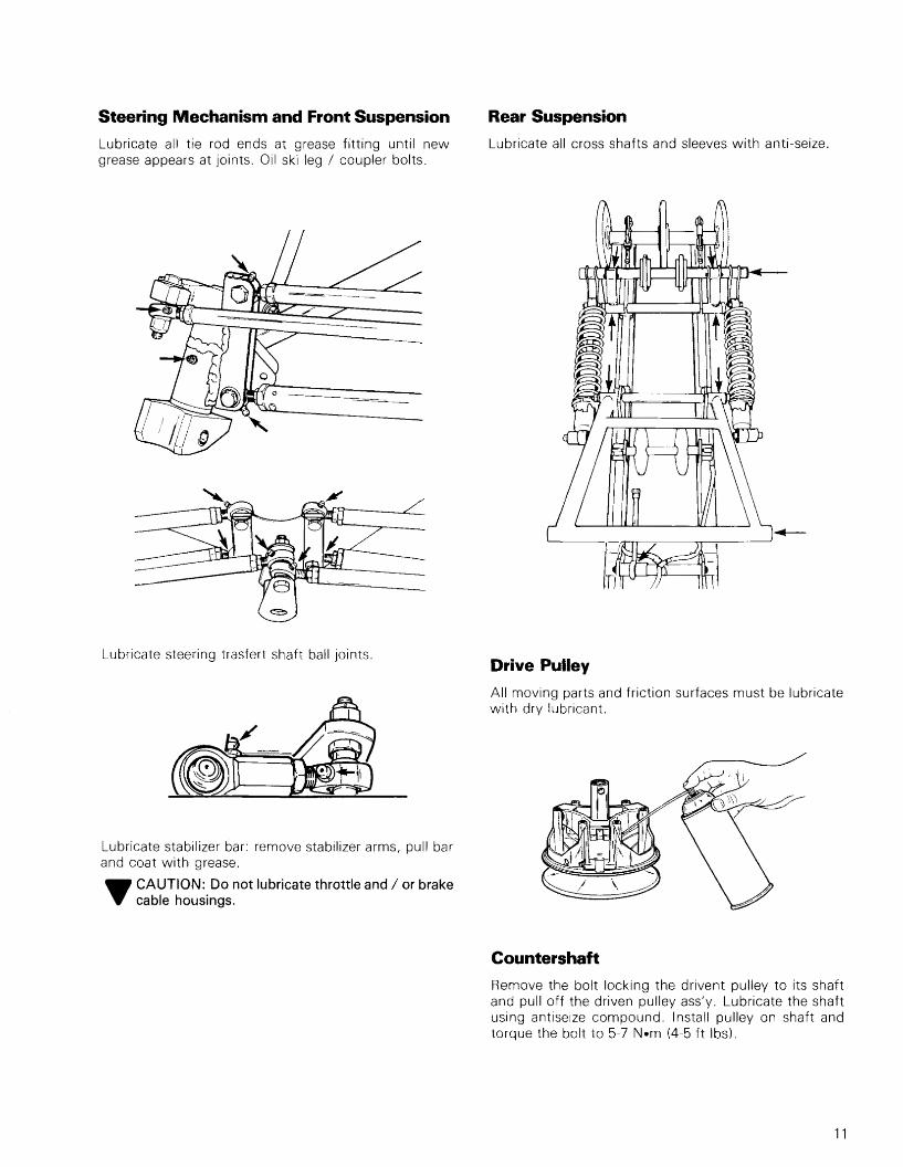
Steering Mechanism and Front Suspension
Lubricate all tie rod ends at grease fitting until newgrease appears at joints. Oil ski leg I coupler bolts.
Lubricate steering trasfert shaft ball joints.
Lubricate stabilizer bar: remove stabilizer arms, pull barand coat with grease.
... CAUTION: Do not lubricate throttle and / or brake.. cable housings.
Rear Suspension
Lubricate all cross shafts and sleeves with anti-seize.
Drive Pulley
All moving parts and friction surfaces must be lubricatewith dry lubricant.
Countershaft
Remove the bolt locking the drivent pulley to its shaftand pull off the driven pulley ass'v. Lubricate the shaftusing antiseize compound. Install pulley on shaft andtorque the bolt to 5-7 N-m (4-5 tt-lbs).
11
MAINTENANCE PROCEDURES
Pulley Guard Removal
•WARNING: Engine should be running only whenpulley guard is secured in place.
Drive Belt Removal
•WARNING: Never start or run engine withoutdrive belt installed. Running an unloaded engine
is dagerous.
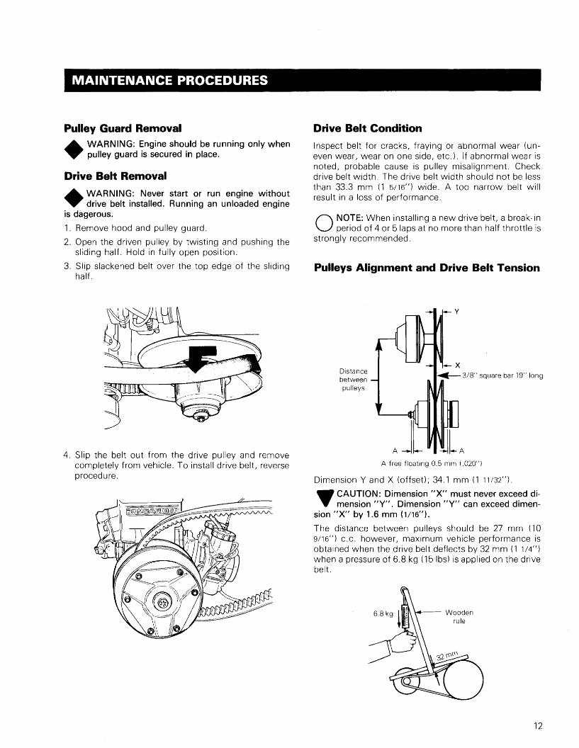
1. Remove hood and pulley guard.
2. Open the driven pulley by twisting and pushing thesliding half. Hold in fully open position.
3. Slip slackened belt over the top edge of the slidinghalf.
Drive Belt Condition
Inspect belt for cracks, fraying or abnormal wear (uneven wear, wear on one side, etc.). If abnormal wear isnoted, probable cause is pulley misalignment. Checkdrive belt width. The drive belt width should not be lessthan 33.3 mm (1 5/16") wide. A too narrow belt willresult in a loss of performance.
O NOTE: When installing a new drive belt, a break-inperiod of 4 or 5 laps at no more than half throttle is
strongly recommended.
Pulleys Alignment and Drive Belt Tension
y
A free floating 0.5 mm (,020")
Distancebetweenpulleys
Dimension Y and X (offset); 34.1 mm (1 11/32"}.
... CAUTION: Dimension "X" must never exceed di,. mension "Y". Dimension "Y" can exceed dimen-
sion "X" by 1.6 mm (1/16").
The distance between pulleys should be 27 mm (109/16") c.c. however, maximum vehicle performance isobtained when the drive belt deflects by 32 mm (1 1/4")when a pressure of 6.8 kg (15Ibs) is applied on the drivebelt.
4. Slip the belt out from the drive pulley and removecompletely from vehicle. To install drive belt, reverseprocedure.
12

To obtain the proper belt deflection the driven pulley isequiped with three adjusting screws which increases ordecreases the distance between pulley halves while atthe same time attaining exact belt tension.
Adjusting ,,~....-n'_
screws
Adjustment
Equally tighten or slacken the adjusting screws in orderto obtain the recommended belt deflection.
.., CAUTION: Ensure that the pulley width between... each halves is the same all around.
Using shims, adjust the driven pulley in order to have afree-play of 0.5 mm (,020") on each side.
Drive Pulley
Drive pulley is assembled with a 75 Ibs rated release spring(color coded blue).
Two optional release springs are supplied:
color code: sliverspring rate: 60 Ibs/in
- color code: yellowspring rate: 85 Ibs/in
If more R. P.M. is needed, use a release spring with ahigher spring rate and inversely.
O NOTE: To obtain maximum output horsepower,pulley calibration must keep maximum engine R.P.M.
to 9200.
13

Lubricate
DRIVE PULLEY SERVICE PROCEDURE
1-
Set screwseating hole
16
17
/
_e«: install new washer
1~~ ~21
7. Fixed face with post2. Movable face with insert3. Duralon insert4. Locking ring5. Pivot pin kit6. Cam arm kit7. Spacer8. Spider9. Allen set screw
10. Pin11. Steel thrust washer12. Roller
73. Fiber thrust washer14. Wear button kit15. Spring16. Cover17. Steel cover with insert18. Hexagonal indented washer head bolt
1/4 - 20 X 3/419. Pilot washer20. Internal tooth lockwasher21. Hexagonal head cap screw
1/2 20 x 6 112 - GR.822. Drive belt
14

+W ARNING: Drive pulley repairs that include anydisassembly or assembly procedures must be per
formed by an authorized Bombardier dealer, or by a professional mechanic familiar with this type of pulley.Sub-component installation and assembly tolerancesrequire strict adherence to procedures detailed.
Drive Pulley Removal and InstallationProcedure
Tools required:
I--·~(({t{«([((((a
'-- II......« (x)J
Clutch puller tool PIN 414381300
Spider grunt tool PIN 414381400
~--------,The grunt tool is approximately 66 mm (26") long.
Pulley Removal
With engine cold remove the spark plugs then bring thep.T.a. piston to T.D.C. (top dead center).
Rotate drive pulley 45° clockwise then insert enoughstarter rope into the cylinder to fill it completely.
.., CAUTION: Do not rotate the pulley more than 45°.... otherwise the rope may enter the engine port and
cause serious engine damage.
Remove the drive pulley retaining bolt.
Remove the drive pulley using puller PIN 414381300 orequivalent.
Spring replacement procedure:
IMPORTANT: Before disassembling the drive pulley, allcomponents should be marked for proper assembly.
O NOTE: The drive pulley spring can be replacedwithout removing the drive pulley from the engine
In both cases, the same procedure applies.
Remove the retaining plate by loosening the screws inan alternating sequence to prevent bending the plate.
+WARNING: Spring pressure can force assemblyapart, therefore, it is emperative that the governor
cup be held firmly during screw removal.
.., CAUTION: Make sure you do not bend the retain". ing plate during removal or assembly.
Should the cover be accidently bent, replace with a newone.
Remove the spring.
Install the new spring.
Reassemble making sure that the plate retaining screwsare tighten in a sequence to avoid bending the plate.
O NOTE: To further disassemble the drive pulley, thepulley ass'v should be completely removed from the
engine.
+WARNING: When disassembling the rest of thedrive pulley, do not use a hammer to remove pins,
etc. Any bending or fractures that are created whiledisassembling or reassembling the pulley can be thecause of serious damages when unit is operated at highR.P.M.
15

Disassembly
After removing the spring and the dust cover, the spidercan be removed.
Remove the set screw@.
~ CAUTION: Use extreme care in removing the spi... der from the main post. Do not use a hammer or
similar. Use only the grunt tool PIN 414381400 or a similar device.
IMPORTANT: To ease disassembly, heat the spider to80°-100°C (175°-212° Fl. This will expand the spider andbread the Loctite bond.
Install the grunt tool PIN 414381400, one arm used tohold the ass'y fixed, the other arm used to loosen thethreads.
Reassembly
For reassembling, reverse the disassembly procedure,making sure that all parts are installed in their properassembly order.
Apply "Loctite 271" red (high strength) on the spidermain post threads, and on the threads of the set screw@.
Tighten the spider (using the grunt tool) so that the setscrew @ will rest in the hole of the main post, using"Loctite 271" red (high strength).
~ CAUTION: Always install new roll pins on the cam... arm retaining pins ® and new washers on ® ®@ @. Replace all parts that show signs of wear ordamage.
IMPORTANT: Lubricate all moving parts and frictionsurfaces with a dry lubricant PIN 414 3815 00.
Pulley Installation
~ CAUTION: Prior to installation clean the crank... shaft taper with fine steel wool and acetone. Dry
with a clean dry cloth.
Lock the crankshaft in position as explained in the removal procedure. Make sure the crankshaft is rotated45° counter-clockwise from T. D. C. and that the cylinder is completely filled with starter rope.
~ CAUTION: Do not rotate the crankshaft more than... 45°, otherwise the rope may enter the engine portand cause serious engine damage.
Install the drive pulley assembly on the crankshaft.
Install a new internal tooth lockwasher ® on the retaining bolt.
Torque the pulley retaining bolt to 85 N-m (63 ft-lbs).
Remove the rope from the cylinder and reinstall the sparkplugs.
Reinstall the drive belt.
Raise and block the rear of the vehicle off the ground.
Install the pulley guard and close the hood .
•WARNING: Before starting the engine, make surethat the track is free off all particles which could be
thrown out while track is rotating. Keep hands, tools,feet and clothing clear of track. Ensure rio-one is standingin close proximity to the vehicle.
Start the engine and repeatedly apply the throttle and thebrake.
Stop the engine and re-torque the pulley retaining bolt to85 N-m (63 ft-bls).
16

t afcle
x l! x ::: )(
k '; x "x x
- - - I- - I-----
- -~- - - I----
~X •
X x : ~ x franx x ~ vehix ~ K_ ~
I- - r--- •x- - xl--- -
x X • x Xx •x x x
PTO side
MAG side
Track Cleating
Track position:
The side of the track having only outside guides must beon MAG side.
Track spiking
• Hard iced race track:• KickerX Steel spike
If necessary to adjust, loosen the idler wheel (retainingbolts) and slacken the adjuster bolt lock nuts.
Then, screw or unscrew the adjuster bolts to center thetrack.
• Soft iced race track: replace steel spikes for carbidetip spikes or triangular spikes.
O NOTE: Track tension and alignment are interrelated. Do not adjust one without the other .
Start the engine and accelerate slightly so that trackturns slowly. Check that track is well centered and turnsevenly . To correct, stop engine then tighten the adjusterbolt on side where track is closest to the frame. Recheckalignment.
Retighten the adjuster bolt lock nut, the idler wheel retaining bolts and recheck alignment.
•WARNING: Before checking track aligment, ensure that the track is free of all particles which could
be thrown out while track is rotating. Keep hands, tools,feet and clothing clear of track. Ensure rio-one is standing in close proximity to the vehicle.
Lift rear of the vehicle and support it off the ground sothat the track is free to turn. Rotate track by hand andvisually inspect the condition, pay attention to cross linksand rivets. Immediately replace cracked cross links andloose or/and missing rivets.
•WARNING: Do not operate a snowmobile with acut, torn or damaged track.
•WARNING: Too much tension will result in powerloss and excessive stresses on cross links and
suspension components.
t6-13mm (1i4·1/2")
Track Adjustment
Raise the rear of vehicle and support with a mechanicalstand. Allow slide to extend normally. A gap of 6-13 mm(1/4-1/2") should exist between slider shoe and crosslinks. If the track tension is too loose, the track will have atendency to thump.
...CAUTION: Do not overtighten the chain sprocket... adjustment screw.
Track Condition
The tension is correct when there is a deflection fo 6-8mm (1/4 5/16") towards the exterior . Tension is adjustedby slightly tightening the tensioner sprocket against thechain and by locking it in position.
Drive Chain Tension
17

Suspension Condition
Visually inspect suspension springs. Replaceany weak orbroken spring. Inspect shoe condition of slide suspensionand replace as necessary.
Front Suspension Adjustment
O NOTE: The camber is the tilting of the ski leg/skifrom the vertical. To obtain a negative camber the
ski leg/ski must be tilt inward, so that the ski legs arecloser together at the top than at the bottom. Theamount of tilt is measured in degrees from the vertical.The measurement is called camber angle.
0° camber
105.4 em (41 112")'<i;!Y...4---- ski stance ---....~t:I
2° - 5° negative camber
Lower the vehicle at the floor and work the suspensionup and down so that all the suspension componentshave a chance to move.
It is recommended, to recheck camber adjustmentthrough the whole procedure.
Recheck all bolts and locking nuts and ensure thatthe ski stance remains at 105.4 cm (41 1/2") fromcenter to center of skis.
O NOTE: Always ensure to maintain the ski stanceof 105.4 cm (41 1/2") while performing this adjust
ment.
To adjust the camber:
Loosen the lock nuts of the upper and lower front arms.Turn the arms manually until recommended camberangle is reached. Firmly retighten lock nuts.
, 6-13 mm (1/4112")
gap under skis
O NOTE: This adjustment must be performed withthe hood removed.
Camber adjustment
Ensure that the front suspension is totally extended andthat the skis are straight.
With the angle finder and a straight edge (laid flat onthe ski leg top portion) adjust the camber as recommended.
Prior to any suspension and/or steering adjustmentalways perform the following adjustments in the described sequence.
1. Camber adjustment2. Handlebar adjustment3. Toe out adjustment
Proceed as follows to adjust:
- Place the vehicle on an horizontal surface.
Lift the front of the vehicle (using two wooden blocksinstalled under the bottom plate) in order to obtain agap of 6-13 mm (1/4-112") under each ski when thefront suspension is totally extended.
Ski legtop portion
Camber L.H. (sitting on vehicle) 0°Camber R.H. 2° - 5° negative
18

Stabilizer bar adjustment
The stabilizer bar has three \3} interchangeable attachment positions to suit the drivers preference.
1. Front light2. Center - medium3. Rear firm
The stabilizer bar should always be free of any tensionwhile performing suspension adjustment or selectingone of the three (3) attachment positions. This is obtained by varying the length of the retaining tie rods.
Weight transfer adjustment
O NOTE: This adjustment is only recommended forflat track racing.
Weight transfer adjustment is possible by raising theright hand side of the frame in order to keep the machine horizontal while cornering on a flat track.
The right hand side shock absorber top retaining screwis adjustable.
IMPORTANT: The R.H. frame height must not exceed25 mm (l ") above the left hand side.
To adjust proceed as follows:
With the vehicle on the ground
- Disconnect the R.H. stabilizer bar tie rod from arm.
Unlock the R.H. shock absorber top retaining nut.
- Screw or unscrew the lower nut to adjust the frameheight to the rider's preference.
Measure the distance from the ground to the top of thestabilizer bar arm on both sides to obtain the desiredheight.
After the desired height is obtained re-install the stabilizer bar tie rod bolt and lock the shock absorber toplock nut.
Remember, the stabilizer bar should always be free ofany tension when performing adjustment. The length ofthe retaining tie rod can be altered.
O NOTE: When racing on a banked track it is recommended to keep the frame height equal on both si
des.
Shock absorber adjustment
Ski shock absorbers are adjustble to suit a driver'sparticular preference. This adjustment includes, adamping action adjustment as well as spring preloading adjustment.
Damping action adjustment
The damping action has three possible variations, regular, firm or extrafirm.
Remove the shock absorber from the vehicle and installthe lower retaining eye in a vise. Unscrew the upper aluminum stopper on the shaft.
Using two (2) screwdrivers, remove the shock springcollar, the spring, and the stopper.
19

Fully collapse the damper rod, ensure to align the topcollar mark with the identification mark on the shockbody.
Top collarmark
Bodyidentification
To locate the existing adjustment, turn the damper rodcollar mark slowly over the body identification marksuntil engagement can be felt then turn in required direction to attain desired position.
Preloading
- To adjust the spring preload, the cam collar can beturned clockwise to increase, counter-clockwise todecrease. A high spring preload will increase the vehicle carrying capacity.
Steering Mechanism
Inspect steering mechanism for tightness of components (steering arms, tie rods, ball joints, ski couplerbolts, etc.). If necessary, replace or retighten. Checkcondition of skis and ski runners. Replace if worn.
Steering Adjustment
Prior to any suspension and/or steering adjustmentalways perform the following adjustments in the decribed sequence.
1. Camber adjustment2. Handlebar adjustment3. Toe out adjustment
Handlebar adjustment
Disassemble the steering arm ball joint (located at frontof track tunnel.)
Set the handlebar to form a 900 angle with the frameand position the steering transfer shaft attachmentbracket at a vertical position.
+W ARNING: Always ensure that the steering transfershaft attachment brackets are vertical when the
steering arm is positioned at a 20° angle with the attachment brackets.
20° angle --"'1
Steering arm
Re-adjust the length of the ball joint assembly and reinstall to the steering.
20

•WARNING: The handlebar to steering transfershaft ball joint assembly length must not exceed
76 mm (3") center to center of ball joints.
Rear Suspension Adjustment
Two different adjustments are possible:Preload adjustment
Front limiter adjustment
Preloadcam
Front limiterm.........--+!-Hl---.;!t-+-- adjustment
Preload Adjustment
To adjust the spring preload, the cam collar can beturned clockwise to increase, counter-clockwise todecrease. A high spring preload will increase the vehicle carrying capacity.
'-- Steering rod ....
411----Toe out of 3.2 4.8 mm ---.......\~:!1\1/8·3/16")
measured behind ski handle loop
Toe out adjustment
Skis should have a toe out of 3.2 mm (1/8"l minimum to4.8 mm (3/16") maximum. To check, measure distancebetween skis at front (behind ski handle loop) and rearof outside edge.
To adjust:
Ensure that the steering transfer shaft ball joint attachment brackets are vertical and that the skis are pointeddirectly forward.
Loosen the lock nuts of each tie rod. Equally turn the tierods manually until skis are properly aligned. Firmlyretighten lock nuts.
•WARNING: The ball joint socket must run parall~1with the steering arm. The socket must be restrai
ned when tightening the tie rod end lock nuts. The handlebar should form a 90° angle with the frame, whenthe skis are pointed forward.
Front limiter adjustment
- Place the vehicle on an horizontal surface.
Raise the front of the vehicle (using two woodenblocks installed under the bottom plate) in order toobtain a gap of 6-13 mm (1/4-1/2") under each skiwhen the front suspension is totally extended.
Track contacts theground at the rear of
the idler bracket
6-13 mm\ 1/4·1/2"}
under skis
- Adjust the front limiter until the front portion of thetrack (at the rear of the idler bracket) comes in contact with the ground.
21

Cooling SystemBy lifting the radiator cap lever check that cap pressurizesthe system. If not,install a new 141bpressure radiator cap.
Using an hydrometer check that the anti-freeze solutionis strong enough for the temperature in which the vehicle is operated.
If coolant temperature is above 80°C (180°Fl check thatthe radiator is not obstructed with grim or foreign material.
To drain the cooling system
•WARNING: Never drain the cooling system whenhot and under pressure. Serious burns from cool
ant may occur.
Release the pressure in the system by lifting the lever incorporated on the pressure cap.Remove the radiator pressure cap .
•WARNING: Before removing the cap, always release the pressure by lifting the lever incorporated
on the cap, loss of fluid and the possibility of severeburns could occur.
Drain the cooling system by disconnecting the by-passhose from the engine head elbow, then block off theelbow and open the radiator drain valve. (Located onthe lower portion of the radiator] then lower the bypasshose to drain engine.
To refill the cooling system
Close the radiator drain valve, open the bleeder screw,pour in the liquid until it reaches the bleeder, close thebleeder screw.
Bleederscrew
Position the disconnected end of the by-pass hosehigher than the engine head, then pour in the liquid untilit reaches the elbow fitting on the engine head. Reconnect the hose.
Continue to slowly pour the liquid in the tank until thecoolant level reaches the lower portion of the upperreturn hose.
Upper returnhose
Re-install tank cap and start engine; let engine run untilit reaches its operating temperature .
•WARNING: Before removing the radiator pressurecap always release the pressureby filting the lever in
corporated on the cap, loss of fluid and the possibility ofsevere burns could occur.
Coolantlevel
--_/
Drainvalve --.....,;.........\.~'r--,...J I
On the system has been drained, unblock the elbow.
O NOTE: To completely drain the system the elbowhas to be blocked, otherwise no syphoning effect
will be produced and a certain quantity of liquid will remain in the system.
~ CAUTION: To prevent rust formation in the cool.. ing system, always replenish ghe system with the
recommended solution. (60% antifreeze 40% water).
22

Engine Head NutsAfter the first 5 hours of operation, check that enginehead nuts are tight and equally torqued to 22 N.m i16tt-lbs) when cold.
Carburetor Adjustment
The carburetor adjustments are: Air Screw Adjustment,Throttle Slide Adjustment and Idle Speed Adjustment.
Throttle slideadjustment
Engine Mount Nuts
Check engine mount nuts for tightness. Retighten if necessary.
Check spark plug gap unsing a wire feeler gauge. Gapmust be 0.40 mm (,016"). Reinstall plugs and connectwires. Correct spark plugs are Bosch W 340 S2S orequivalent.
/:D-ll1I-- Cable adjuster
•WARNING: It is important that the throttle slideadjustment be performed to ensure proper func
tioning of the throttle mechanism.
C) Idle speed adjustment
Turn idle speed screw clockwise until it contacts thethrottle slide then continue turning two (W) additionalturns. This will provide a preliminary idle speed setting.Start engine and allow it to warm then adjust idle speedto 3000-3500 RPM by turning idle speed screw clockwise or counter-clockwise.
.., CAUTION: Do not attempt to set the idle speed by... using the air screw. Severe engine damage can
occur.
A) Air screw adjustment
Completely close the air screw (until a slight seatingresistance is felt), then back off screw to specification.
S) Throttle slide adjustment
•WARNING: Ensure the engine is turned OFF, priorto the throttle slide adjustment.
With the throttle cable adjuster jam nut unlocked, pressthe throttle lever against the handle grip. Unscrew thecable adjuster manually to obrain maximum carburetorslide opening. Check with your finger if the carburetorslide is well seated against the carburetor top portion).Then, screw the cable adjuster in two turns in order tonullify any possible tension on the throttle cable then,tighten the cable adjuster jam nut.
FouledIblack)
Overheated{light grey)
Exhaust System
The engine / exhaust system parts are vital toward efficient muffler function. Check all attachments. Replacesprings and / or tighten if necessary.
.., CAUTION: Do not operate vehicle with exhaust... disconnected otherwise serious engine damage
will occur.
Spark PlugsDisconnect spark plug wires and remove spark plugs.Check condition of plugs.
• A brownish tip reflects ideal condition (correct carburetor adjustment, spark plug heat range, etc.).
• A black insulator tip indicates fouling caused by: carburetor idle speed mixture and / or high speed mixture too rich, incorrect fuel mixing ratio, wrong typeof spark plug (heat ranqel, or excessive idling.
• A light grey insulator tip indicates a lean mixturecaused by: carburetor high speed mixture adjustedtoo lean, wrong spark plug heat range, incorrect fuelmixture ratio, or a leaking seal or gasket.
23

Ignition Timing Procedure
Foreword
On models equipped with a Bosch C. D. ignition system,plug firing is initiated by an electrical pulse. This pulse isreleased when a metal projection on the flywheel hubrotates near the trigger coil. Therefore, timing must beperformed while the engine is running.
A stroboscopic timing light such as Sun PTL 45, Snap-OnMT 215B, Bosch EFAW 169A, or a suitable equivalent,plus a 12 volt battery are needed.
Ignition timing
Timing procedure for this engine type is composed offour main phases, all being equally important.
1. Position of the armature plate.
2. Position of the timing marks on magneto ring.
3. Air gap between trigger coil and magneto ring.
4. Timing verification using a stroboscopic timing light.
1. To obtain best generator coil performance, position thearmature plate on the crankcase with the retaining capscrews in the middle of the plate slots.
~ CAUTION: When asembling magneto ring on... crankshaft, clean crankshaft extension (cone)
and threads. Apply "Loctite 242" (no. 413 7025) oncone and threads. Torque bolt to 80 N·m (60 ft-lbs).
2. Check the position of the timing marks (for each cylinder) on magneto ring: repunch if necessary.
With the piston positioned at 3.41 mm L134") B.T.D.C.,magneto ring mark should align with central mark oncrankcase (around timing hole).
24

3. Check air gap between magneto ring and trigger coil.The gap should be 0.6 to 0.9 mm 1.023" to .035").
O NOTE: It is recommended to use a brass feelergage.
4. Check timing using a stroboscopic timing light (oneach cylinder).
•WARNING: Place ski tips against the wall, raiserear of vehicle so the track is not in contact with
the ground andptace it on a stand equipped with aprotector. Make sure nobody passes behind the vehicle during timing procedure.
Magneto ring mark and crankcase central markshould align at 5000 R.P.M.
Magnetoring mark
If necessary to adjust: unscrew slightly the two (2)screws holding trigger coil bracket, then move bracket up or down.
If correct timing is impossible with trigger coil bracket travel, stop engine, remove bracket from crankcase and relocate the trigger coil on its bracket.
... ...
Vehicle General Inspection
Check electrical wiring and components, retighten looseconnections. Check for stripped wires or damaged insulation. Thoroughly inspect the vehicle and tighten loosebolts, nuts and linkage. Inspect skis and ski runners forwear.
Tail Light Bulb
The taillight bulb must always be on when the engine isrunning. If the taillight bulb is burnt, expose bulb byremoving red plastic lens.
25

TROUBLE SHOOTING GUIDE
SYMPTOMS
Engine fails to start or does not start easily
Good spark but engine runs on one (1) cylinder
Engine operation is erratic at low speed
Engine stalls frequently
No acceleration
Idles well but dies down when put to full throttle
CAUSE
No fuel to carburetoral clogged fuel filterbl clogged fuel linec) faulty carburetor float needle
Insufficient compressiona) crankcase compression leaks at sealb) crankcase compression leaks at crankcase
mating surfacescl rotary valve cover leaksd) worn or stuck piston ringel improper timing of rotaty valve
No spark at pluga) fouled or wet plugb) faulty CD boxc) faulty generating coild) open or short circuit in armature platee) faulty spark plug protectorf) shorted tether switch
Bad CD boxFaulty spark plugSeized piston
Crankshaft seals leakCarburetor air screw is improperly adjustedIncorrect float levelExcessive spark plug gap or dirty electrodesIncorrect ignition timingFaulty CD boxShort circuit in armature plate
Fouled plugRestriction in the gas cap ventClogged fuel linesClogged carburetor jetsCrankcase compression leaksRubber flanges or rotary valve cover leaks
High speed jet too lean or obstructed
Float level too lowChoke partly closedFuel line or fuel filter cartridge obstructedEngine improperly timed
26

SYMPTOMS CAUSE
Engine does not have sufficient power Worn cylinder and worn or stuck piston ringsIncorrect ignition timingIncorrect spark plug gapClogged carburetor jetsIncorrect float height
Vibrates excessively or runs rough and smokes Idle or high speed mixture adjustment too richEngine mount looseWater in gasoline
Engine overheats Excessive carbon deposit on cylinder headLean fuel/air mixtureIncorrect ignition timingSpark plug range too hotCoolant level to lowCoolant pump inoperativeAir pocket in cooling system
Engine operation is erratic at high speed Spark plugs are improperly gapped, dirty or faultyCrankcase compression leaksIncorrect carburetor float levelBroken or cracked tuned exhaustShort circuit in armature plateFaulty CD box
High speed back-firing Lean carburetor adjustmentCarbon formation on spark plugCrankshaft seal leaksLoose armature plate
Ignition fails to spark Fouled spark plug or faultyDefective CD boxShort circuit in armature plateImproper ground of ignition system
Spark plug electrodes are fouled Rich carburetionIncorrect gas / oil ratioIncorrect spark plug heat range
Spark plug electrodes are burned Incorrect heat rangeOverheating engineIncorrect ignition timingLoose spark plugLean mixture
27

SYMPTONS CAUSE
Uneven belt wear Improper alignmentLoose engine mountRough or scratched pulley surfaces
Belt turns over Pulley misalignmentEngine over-revs.Incorrect gear ratio
Drive pulley fails to fully disengage Weak or broken springPulleys misalignedSliding half sticking
Engagement speed too low Weak or broken springWrong belt installedIncorrect counterweights installed
Engagement speed too high Incorrect springHollertsl wornIncorrect counterweights installed
Erratic engagement Roller(s) wornStretched, deformed or broken spring
Creeping at idle Too great a center to center distance between pulleysIncorrect drive beltPulleys misalignedIncorrect spring
Poor top speed Sliding half bindsIncorrect driven pulley spring tension
Engine loads Weak or broken driven pulley spring
28

STORAGE
IMPORTANT: It is during summer, or when a vehicle isnot in use for any length of time that proper storage is anecessity. Storage of the snowmobile during long periods of inactivity consists of checking and replacingmissing broken or worn parts; proper lubrication andtreatments to insure that parts do not become rusted;cleaning items such as carburetor of oil mixtures, to prevent gum varnish formation within the carburetor; andin general, preparing the vehicle so that when the timecomes to use the snowmobile again it will start and be intop condition.
•WARNING: Only perform such procedures as detailed in this manual. It is recommended that dea
ler assistance be periodically obtained on other components / systems not covered in this manual. Unlessotherwise specified, engine should be turned OFF for alllubrication and maintenance procedures.
Drainvalve --..,--,
Once the system has been drained, unblock the elbow.
O NOTE: To completely drain the system the elbowhas to be blocked, otherwise no syphoning effect
will be produced and a certain quantity of liquid will remain in the system.
.., CAUTION: To prevent rust formation in the coolY ing system, always replenish the system with the
recommended solution. (60% antifreeze 40% water).
To refill the cooling system
Close the radiator drain valve, open the bleeder screw,pour in the liquid until it reaches the bleeder. Close thebleeder screw.
Cooling System
During prolonged storage it is recommended to completely drain the cooling system and refill with a new solution of coolant.
To drain the cooling system
•WARNING: Never drain the cooling system whenhot and under pressure. As serious burns from
coolant may occur.
Release the pressure in the system by lifting the lever incorporated on the pressure cap.
Remove the radiator pressure cap.
•WARNING: Before removing the cap c1ways releasethe pressure by lifting the lever incorporated
on the cap, loss of fluid and the possibility of severeburns could occur.
Drain the cooling system by disconnecting the by-passhose from the engine head elbow, then block off theelbow and open the radiator drain valve. (Located onthe lower portion of the radiator) then lower the by-passhose to drain engine.
Drainvalve
Bleeder __~.t.""-Io_
screw
Position the disconnected end of the by-pass hosehigher than the engine head, then pour in the liquid untilit reaches the elbow fitting on the engine head. Reconnect the hose.
Continue to slowly pour the liquid in the tank until thecoolant level reaches the lower protion of the upperreturn hose.
Engine head elbowBy-pass hose
29

Re-install tank cap and start engine; let engine run untilit reaches its operating temperature.
Stop engine and check coolant level; refill as necessary.
•WARNING: Before removing the radiator pressure cap, always release the pressure by lifting the
lever incorporated on the cap, loss of fluid and the possibility of severe burns could occur.
TrackInspect track for cuts, loose or broken cross links andrivets. Make any necessary replacement. Lift rear ofvehicle until track is clear of ground then support withbrace or trestle. The snowmobile should be stored insuch a way that track does not stay in contact with cement floor or bare ground.
O NOTE: The track should be rotated periodically,(every 40 days). Do not release track tension.l
.., CAUTION: To prevent track damage, temperatureY in the storage area must not exceed 38°C (100°F).
Suspension
Remove any grime or rust. Check slider shoe condition.Replace as necessary.
Skis
Wash or brush all grime or rust accumulation from skis.Grease ski legs at grease fittings. Check condition ofskis and ski runners. Replace if worn.
Slider Shoe Lubricant TankCheck hoses for signs of leakage. Also check tightnessof fittings on slide, check valve and tank.
Fuel Tank
Remove cap then using a syphon, remove gasoline fromtank .
•WARNING: Gasoline is flammable and explosiveunder certain conditions. Always perform proce
dures in a well ventilated area. Do not smoke or allowopen flames or sparks in the vicinity.
Carburetors
The carburetors must be dried out completely to prevent gum formation during the storage period .
Assure that the inlet line is disconnected. Remove drainplug of the float chamber of each carburetor. Drain carburetors.
Reinstall plug and connect fuel line.
Cylinder Lubrication
Engine internal parts must be lubricated to protect cylinder walls from possible rust formation during the storage period.
O NOTE: This operation should be repeated every 40days during storage.
Remove spark plugs. Operate rewind starter to bringpiston at top position. Pour the equivalent of onespoonful of oil into spark plug hole.
Slowly crank engine several times using manual starter.Repeat above steps for other cylinder. Install sparkplugs.
30

Drive Pulley
Inspection, cleaning and lubrication should be performed at the end of each racing season.
All the moving parts and friction surfaces must be lubricated with a dry lubricant.
Chaincase
Drain the chaincase completely and refill to proper levelusing fresh chaincase oil. To drain, remove chaincasecover.
Controls
Lubricate steering mechanism. Inspect components fortightness, (ski coupler bolts, steering arm locking bolts,tie rods, ball joints, etc.). Tighten if necessary,
• WARNING: Do not lubricatethrottle cable housing.
Coat electrical connections and switches with a greaseless metal protector. If unavailable, use petroleum jelly.
ChassisClean the vehicle thoroughly, removing all dirt andgrease accumulation.
~ CAUTION: Plastic alloy components such as fuel• tank, etc., can be cleaned using mild detergents or
isopropyl alcohol. Do not use strong soaps, degreasingsolvents, abrasive cleaners, paint thinners, etc.
Inspect hood and repair damage. Repair kits are available at your authorized dealer. Clean frame (Use onlytI Aluminum cleaner" and follow instructions on container),
Touch up metal spots where paint has been scratchedoff. Spray all bare metal parts of vehicle with metal protector. Wax the hood for better protection.
O NOTE: Apply wax on glossy finish of hood only.Protect the vehicle with a cover to prevent dust
accumulation during storage.~ CAUTION: If for some reason the snowmobile has• to the stored outside it is necessary to cover it with
an opaque tarpaulin. This caution will prevent the sunrays affecting the plastic components and the vehiclefinish.
General Inspection
Check electrical wiring and components, retighten looseconnections. Check for stripped wires or damaged insulation.
Thoroughly inspect the vehicle and tighten loose bolts,nuts and likage.
O NOTE: Leave drive belt off pulleys for the entirestorage period.
31

GEAR RATIO CHART
R.P.M. TOP GEAR RATIO 1 T01
9200 15 T 77.7 M.P.H.9200 16 T 82.9 M.P.H.9200 17 T 88.1 M.P.H.9200 18 T 93.3 M.P.H.9200 19 T 98.5 M.P.H.9200 20 T 103.6 M.P.H.9200 21 T 108.8 M.P.H.9200 22 T 114.0 M.P.H.
Calculation example
To find the vehicle top speed with
- bottom gear: 40 teethtop gear : 19 teethR.P.M. : 9200correction factor: .022537
Ex.: 19 x 9200 x .022537 98.5 M. P.H.40
Top speed is 98.5 M.P.H.
SPECIFICATIONS
ENGINE Type 354No. of cylinders 2Bore 59.5 mmStroke 61 mmDisplacement 339.2 cm3
Compression ratio ± .5 15.5:1Squish area 1.2 mm ('047")Squish angle 14°Rotary valve
opening B.T.D.C. 1370
closing A.T.D.C. 65°Cylinder port timing:
Transfer port 14.4 mm 65°Auxiliary boost port 16.5 mm 69.8°Exhaust port 31.0 mm 98.2°Auxiliary exhaust port 29.5 mm 95.5°
Maximum R.P.M. 9200Piston ring type Keystone "L" with moly fillingPiston to wall clearance (min) 0.13 mm (,0051")Ring end gap 0.15 p 0.30 mm
(,006 - .012")Cylinder head nut torque 22 N.m (16 tt-blslCrankcase bolt torque 21 N.m (15 tt-lbs)Cylinder nut torque 22 N.m (16 tt-lbslEngine support torque 35 N.m (24 tt-lbslMag. wheel torque 80 N.m (60 ft-lbs)
32

CARBURATION Carburetor type Mikuni 2 X VM40Carburetor part number 403 104500Main jet ** sea level 620 mag 580 PDMNeedle jet 224BB5Needle indentification 7DH2-3Needle setting from top 3rd grooveIdle jet 40Throttle slide cut away 2.5 mmAir screw adjustment 1 1/2 turn ± 1/8
Float level Float arm parallel with carburetorbody edge
By-pass hole diameter 1.4 mmIdle outlet diameter 0.7 mmValve seat diameter 1.5 mmStarter jet diameter 1.5 mmIdling R.P.M. 3000 - 3500Gasoline Aviation type light blue 100 LL octane
Light green 100 to 130 octaneOil Blizzard snowmobile oilGas/oil ratio 20/1
** The main jets are identifical during the break-in period.It is necessary to change PTa jet after that period according to dome color.
CAPACITIES Fuel tank5.1. 9 liters
- Imp. gals 2 gals- U.S. gals 2.4 gals
Rotary valve 125 ml 14.3 oz)Cooling system 2500 ml (88 oz)Chaincase 200 ml (7 oz)Track lubricant tank 2190 ml (77 oz)
33

.--
POWER TRAIN Gear ratio 19/40
Drive pulley type Comet high performanceDrive pulley retaining bolt torque 85 N.m 163 tt-lbs)Pressure lever identification Comet A-3Spring length/number/color/rate 104.1 mm (4.100") 414376800 blue
75 in/lboptional 99.5 mm 13.920") 414 3783 00 yellow
85 in/lboptional 11 0.5 mm (4.350") 414 3784 00 silver
65 in/lbClutch engagement R.P.M. 5800 to 6000Driven pulley spring preload 131bsDriven pulley cam pitch lead 10-9-8Pulley center to center distance 26.8 cm (109/16/1)
Offset dimension (nominal X & Y) 34.1 mm 11 11/32")
Belt number: Bomb PIN 414375800Dayco Max. PIN 1103 R 340
Track type Internal drive with reveted steel cleatsTrack length 259 cm (102")Track width 38 cm 115")Track tension (gap) 6-13 mm (1/4 - 1/2")
Drive chain type Silent chainDrive chain pitch 3/8"
* Driven pulley cam available withPitch lead PIN8-7-6 504 1181 008 straight 504 1178 00
o NOTE: To obtain maximum output horse power, pulley calibration must keep maximumengine R.P. M. to 9200.
34

SUSPENSION
STEERING
SKIS
CHASSIS
ELECTRICAL
Type
Shock spring rate:Front- R.H.Front - L.H.Rear
Stabilizer bar diameterStabilizer bar adjustment
Caster L.H.R.H.
Camber - L. H.- R.H.
Handle bar angleSteering/column torqueSteering arm/ski leg torque
Alignment toe outRunner typeStance (center to center)Stance (overall)
Frame materialCab meterialOverall lengthOverall widthOverall heightWet mass.:t 2 kg (5 lbs)
Ignition typeMagneto generator outputSpark plug BoschSpark plug gapSpark plug torqueIgnition timing at R.P.M.Lighting coil resistance *Generating coil resistance *LowHighTrigger coil resistance *Trigger coil gap with mag. ringElectronic advance boxVoltage regulatorFuse (tacho)
TORQUE REACTION
145lbs/in135 Ibs/in25lbs/in
3/4"
Forward lightReward firm
310 fixed310 fixed
0° adjustable2° - 5° (neq.l adjustable
30°40 N-m (30 ft-lbs)40 N.m (30 ft-lbs)
1/8" 3/16"
Carbide41 112"
45"
AluminumFegerglass
243.8 em (96")114.3 em {45"171.1 em (28")
151.7 kg (335 Ibsl
Bosch CDI/RCPK-12V/10W10 watts
W340S2S0.4 mm LOW")
24-29 N.m (17-20 ft/lbsl3.41 mm 24° 31' at 5000 R.P.M.
7.3 ohms
1040 ohms red/yellow48 ohms -red
54 ohms0.6 to 0.9 mm (.023 to .035")
Brown/violet/white wires20 amps.0.1 amp.
* Component temperature must be around 15-20°C (BO-70°F) when testing.Values may vary ± 10%.
35