(Super-)Albatros Variant (Super-)Albatros Vari-HydroAvant fileputting the implement into operation....
36
Serial-No. EN: Operating Instructions Mounted reversible plough (Super-)Albatros Variant (Super-)Albatros Vari-HydroAvant
Transcript of (Super-)Albatros Variant (Super-)Albatros Vari-HydroAvant fileputting the implement into operation....

Serial-No.
EN: Operating Instructions
Mounted reversible plough(Super-)Albatros Variant(Super-)Albatros Vari-HydroAvant


305.2012
Albatros / Super-Albatros
Subject to technical modifications
Please read and follow these operating instructions and notes on safety („For Your Safety“) carefully before putting the implement into operation.The operator must be qualified and trained in the operation, maintenance and safety requirements and instructed about hazards. Please hand all safety instructions to all operators.The applicable accident prevention rules as well as any other generally accepted safety requirements, industrial medicine and traffic regulations must be complied with.
Pay attention to the following “Warning Signs“! (DIN 4844-W9) Notes in these instructions with this sign as well as warning signs at the implement warn against danger!
Caution - Symbol contains notes on safety which must be complied with to prevent dangers to the machine and its function.
Note - Symbol informs about implement specific features which must be complied with to ensure perfect operation of the implement.
Loss of guaranteeThis implement is designed exclusively for normal agricultural operation. Any other utilisation is regarded as not intended use and any damage resulting from this is excluded from liability.The intended use comprises also the compliance with the specified operating-, maintenance and servicing instructions as well as the exclusive use of original spare parts.The utilisation of third party accessories and/or third party parts (wear and spare parts) not approved by Rabe voids any guarantee.Unauthorised repairs or changes at the implement as well as the non-supervision during operation exclude from the liability for any resulting damage.Any complaints at delivery (transport damage, completeness) must be reported immediately. Guarantee claims as well as the terms of the guarantee and the exclusion of liability clause to be complied with pursuant to our terms of delivery.

4 05.2012
Albatros / Super-Albatros
Subject to technical modifications
505.2012
Albatros / Super-Albatros
Subject to technical modifications
Table of contentsLocations of the warn signs at the implement .............................................................................6Locations of the warn signs at the implement .............................................................................7Description of the warn signs ......................................................................................................8For your safety ..........................................................................................................................10
General information ......................................................................................................10General notes on safety ................................................................................................101. Intended use ............................................................................................................102. General notes on safety and accident prevention rules ........................................... 112.1 Mounted implements .............................................................................................. 112.3 Hydraulic system ....................................................................................................122.4 Maintenance ..........................................................................................................12
Machine data .............................................................................................................................13Mounting ...................................................................................................................................15Coupling hydraulic hoses (Colour protecting cap) ....................................................................17Turning test ...............................................................................................................................17Presetting .................................................................................................................................18Traction point .............................................................................................................................18First furrow working width .........................................................................................................19Field work ..................................................................................................................................20Working depth ...........................................................................................................................20Inclination / Tilt ..........................................................................................................................20Traction point and first furrow working width .............................................................................21Working width adjustment ........................................................................................................22Levelling bars ...........................................................................................................................22Pick-up arm for plough follower .................................................................................................23Standard skimmers / Skimmers ................................................................................................24Trash boards .............................................................................................................................24Disc coulter ..............................................................................................................................25Subsoil decompactor ................................................................................................................25Plough leg overload protection .................................................................................................26Automatic stone protection “HydroAvant” ..................................................................................27Transport - Ploughs without combination wheel ........................................................................28Transport - Ploughs with combination wheel .............................................................................28Switching to working position ....................................................................................................28Setting down the plough ............................................................................................................29Maintenance ..............................................................................................................................30Residual dangers ......................................................................................................................32Caution / Transport ...................................................................................................................33

6 05.2012
Albatros / Super-Albatros
Subject to technical modifications
Locations of the warn signs at the implement

705.2012
Albatros / Super-Albatros
Subject to technical modifications
Locations of the warn signs at the implement

8 05.2012
Albatros / Super-Albatros
Subject to technical modifications
General informationWarn signs inform about possible hazards; they inform about the safe operation of the implement.The warn signs are component parts of the implement.The warn signs must always be kept visible (clean) and must be replaced if damaged – they must be purchased from Rabe [for order number: see spare parts list].
9998.02.59
Read operating instructions prior to start-upFollow the safety instructions.Follow transportation and assembly instructions.
9998.02.56
Riding on the implement during operation and transport is not permittedOnly step on the loading ramp or platform during standstill of the implement when it is mounted or securely supported.
The pressure tank is under pressureDisassembly and repair must be done according to the technical manual.
9998.02.85
Take note of the position of the stopcockClose stopcock during road transport. Open stopcock during operation.
9998.02.88
Keep distancePlough turns and slews.Do not stay in the slewing range.
9998.02.52
Description of the warn signs
905.2012
Albatros / Super-Albatros
Subject to technical modifications
9998.02.73
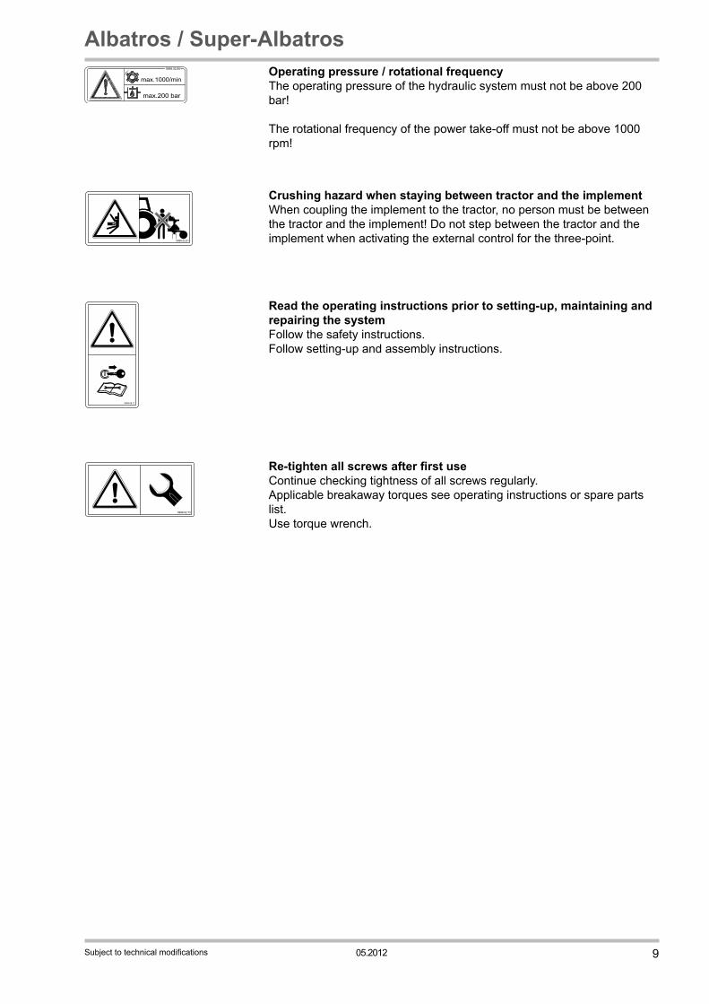
Re-tighten all screws after first useContinue checking tightness of all screws regularly.Applicable breakaway torques see operating instructions or spare parts list.Use torque wrench.
max.1000/min
max.200 bar
9998.02.80 Operating pressure / rotational frequency The operating pressure of the hydraulic system must not be above 200 bar!
The rotational frequency of the power take-off must not be above 1000 rpm!
9998.02.81
Crushing hazard when staying between tractor and the implementWhen coupling the implement to the tractor, no person must be between the tractor and the implement! Do not step between the tractor and the implement when activating the external control for the three-point.
9998.06.17
Read the operating instructions prior to setting-up, maintaining and repairing the systemFollow the safety instructions.Follow setting-up and assembly instructions.

10 05.2012
Albatros / Super-Albatros
Subject to technical modifications
General informationThis section contains general instructions on the intended use of the implement as well as notes on safety which you should follow absolutely to ensure your own safety! This list is very long, some of the notes are not only relevant for the delivered implement. However, the summary reminds of safety rules for the daily operation of machines and implements which are often involuntarily disregarded.
General notes on safetyDuring coupling and uncoupling, no person may stand between the tractor and the implement; Also do not step between the tractor and the implement when operating the external hydraulics control! Risk of injury! Set tractor hydraulics to „position control“ before coupling and uncoupling! Check tractor and implement for operational and traffic safety prior to every operation; the operator is responsible for the „safety“! Ensure sufficient steering safety; if necessary install front weights at the tractor! In the area of the three-point linkage beware of the hazards of crunching and shearing zones! Prior to operating or starting the implement, take care that no person is in the area of the implement! Mounting and riding on the implement and staying in danger area are prohibited! Keep distance! Prior to leaving the tractor, lower the implement, switch off engine and take out ignition key! Settings and maintenance must only be done when the implement is lowered! All safety implements must be installed completely during operation! Take the position of the centre of gravity into consideration when lifting in steep hillside locations (on contour lines). During transport, lock tractor hydraulics control devices against involuntary operation! Prior to the first use – and after extended non-use – check all bearings for sufficient lubrication and tightness of all screws! -maximum length of the combination (traktor+implement) 12m-width 2.55m maximum 3m-maximum height 4m-maximum total weight of the combination 16t, 20% of which on the front axle.
For your safety
1. Intended use The implement is only designed for normal agricultural use (intended use). Any other use is regarded as not intended use. The manufacturer is not liable for any damage resulting from this; the related risk is borne entirely by the operator. The intended use does also comprise the compliance with the operating, maintenance and servicing instructions specified by the manufacturer. The implement may only be used, maintained and serviced by persons who are familiar with this and informed about the dangers. Please hand all safety instructions to all users. The applicable accident prevention rules as well as any other generally accepted safety requirements, industrial medicine and traffic regulations must be complied with. Any unauthorised changes to the implement exclude from the manufacturer‘s liability for any damage resulting from this.

1105.2012
Albatros / Super-Albatros
Subject to technical modifications
2. General notes on safety and accident prevention rules • Check the implement and the tractor for traffic and operational safety prior to every operation!• Follow the generally applicable safety and accident prevention rules!• The warn and information signs fixed at the implement inform about safe operation; Following these signs ensures your safety!• When using public roads follow the relevant regulations!• Prior to starting work, familiarize yourself with all facilities and actuating elements and their functions. During operation of the implement it is too late for this!• Wear tight-fitting clothes. Avoid wearing loosely-fitting clothes!• Keep the implement clean to avoid fire hazards!• Check near zone prior to start-up and operation! (Children!) Ensure sufficient range of vision;• Riding on the implement during operation and transport is prohibited!• Couple the implements properly and attach them only to the specified fixtures!• Special care is required for coupling and uncoupling implements to and from the tractor!• Position the support equipment properly for mounting and unmounting! (Stability!)• Always attach weights properly at the fixing points provided for this!• Comply with the admissible axle loads, total weights and transport dimensions!• Check and install transport equipment - lighting, warning equipment and necessary protection implements!• Triggering cables for rapid action couplings must hang loosely and must not trigger in low position• Never leave the operator‘s cab when driving!• The driving behaviour, steering and braking performance are affected by mounted and semi-mounted implements and ballast weights. Therefore, pay attention to sufficient steering and breaking performance!• When manoeuvring bends pay attention to the wide working radius and the centrifugal mass of the implement!• Operate the implement only if all protection implements are installed and in protective position!• Staying in the working area is prohibited!• Do not stay in the turning and slewing range of the implement!• Power-operated parts (e.g. hydraulic parts) contain crunching and shearing zones!• Prior to leaving the tractor, lower the implement on the ground, switch off the engine and take out the ignition key!• No person may stand between the tractor and the implement without the vehicle being protected against rolling away with the arresting brake and/or with wheel chocks!• Protect folded away frames and excavation facilities in transport position!
2.1 Mounted implements • Prior to mounting and dismounting implements at the three-point linkage: Position the operating implement so that involuntary lifting or lowering is impossible!• For three-point linkage the linkage categories of tractor and implement must agree or must be adjusted!• In the area of the three-point linkage beware of the hazards of crunching and shearing zones!• Also do not step between between the tractor and the implement when operating the external three-point linkage control!• Always pay attention to sufficient side locking of the tractor three-point linkage in the transport position of the implement!• When driving on roads with lifted implement, the operating lever must be bolted against lowering!

12 05.2012
Albatros / Super-Albatros
Subject to technical modifications
2.3 Hydraulic system • The hydraulic system is under high pressure!• Pay attention to the specified connection of the hydraulic hoses when connecting the hydraulic cylinders and motors!• Pay attention to the pressure-free connection both at the tractor and at the implement when connecting hydraulic hoses to the hydraulic system of the tractor!• The coupling sleeves and plugs of hydraulic functional connections between tractor and implement should be labelled to prevent operating errors! Mixing up the connections leads to reverse functions (e.g. lifting/ lowering) - danger of accidents!• Check hydraulic hoses regularly and replace if damaged! The replacement hoses must comply with the technical specifications of the implement manufacturer!• Use suitable tools wenn looking for leakages because of the risk of injury!• Liquids (hydraulic oil) escaping under high pressure may penetrate the skin and cause severe injury! Consult a physician immediately in case of injury! Risk of infection!• Set down implements, depressurise the system, switch off the engine and take out the ignition key before starting any work at the hydraulic system!
2.4 Maintenance • On principle, do any servicing, maintenance and repair works as well as removal of operating errors only when the operating mechanism is switched off and the motor is at a standstill! Take out the ignition key!• Check nuts and screws regularly for tightness and retighten if necessary!• Always secure the implement with suitable supports when doing maintenance works at the lifted implement!• Use suitable tools and gloves when replacing working tools with blades!• Dispose of oils, grease and filters properly!• Always disconnect power before starting any works at the electrical system!• Disconnect the cable at the generator and the battery when doing any electrical welding works at the tractor and the mounted implements!• Any spare parts must at least comply with the technical requirements set by the implement manufacturer! Therefore, use original spare parts to protect yourself!

1305.2012
Albatros / Super-Albatros
Subject to technical modifications
A
H
B
H max.
max. 500 mm
Machine data
Number of furrows 3 4 5 6 Under-beam
clearance cm
Max. height (mm)Type ** Ca. weight kg (for tractor up to ca. kW/hp)
Length A (mm) 2970 3987 4986 5989
75/80 1800
Working width B min. - max. (mm) 990 - 1560 1320 - 2120 1650 - 2650 2040 - 3180
Albatros V 120 M 1026 (96 /130)
1257 (111 /150)
1513 (125 /170) -
Albatros VHA 120 MS 1221 1517 1678
Super-Albatros V 140 M
-
1521 (147 /200)
1767 (162 /220)
2020 (177 /240)
Super-Albatros VHA 140 M 2021 2092 - -
Super-Albatros V 160 M 1580 (162 /220) 1848 (177 /
240) 2080 (192 /260)

14 05.2012
Albatros / Super-Albatros
Subject to technical modifications
Equipment: Beam section 140 or 160 mm, mechanical or hydraulic working width adjustment, hydraulic turning – double-turn, mechanical adjustment of the traction point or hydraulic adjustment via the frame pivoting implement, first body working width adjustment via translation - with spindle or with the hydraulics.
Extra equipment: Standard skimmers/maize skimmers (ca. 35 kg per pair), trash boards (ca. 14 kg), disc coulters (“Variant” back bodies only) – smooth or serrated (ca. 45 kg, spring-loaded 52 kg), sword landside (ca. 6 kg), subsoil decompactor (ca. 26 kg), depth wheel – metal or pneumatic tyres (ca. 95 kg), combination wheel (ca. 145 kg), pick-up arm (ca. 90 kg with “Variant”, 115 kg with “Avant/HydroAvant”), indicator bracket.
“Albatros”: cat.II, III or III short “Super-Albatros”: cat.III or III short (lower link pin replaceable) „Variant“ – with shear protection „Vari-HydroAvant“ – with Hydro stone protection
1505.2012
Albatros / Super-Albatros
Subject to technical modifications
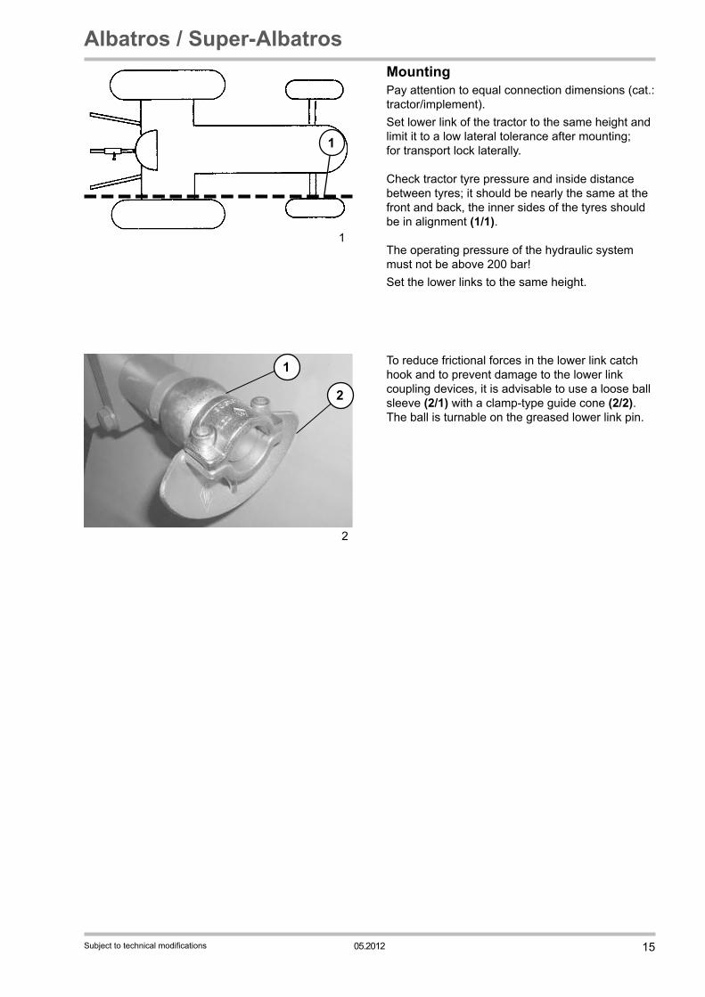
MountingPay attention to equal connection dimensions (cat.: tractor/implement).Set lower link of the tractor to the same height and limit it to a low lateral tolerance after mounting; for transport lock laterally. Check tractor tyre pressure and inside distance between tyres; it should be nearly the same at the front and back, the inner sides of the tyres should be in alignment (1/1). The operating pressure of the hydraulic system must not be above 200 bar!Set the lower links to the same height.
1
1
2
2
1 To reduce frictional forces in the lower link catch hook and to prevent damage to the lower link coupling devices, it is advisable to use a loose ball sleeve (2/1) with a clamp-type guide cone (2/2). The ball is turnable on the greased lower link pin.
16 05.2012
Albatros / Super-Albatros
Subject to technical modifications
4
1
3
2
1
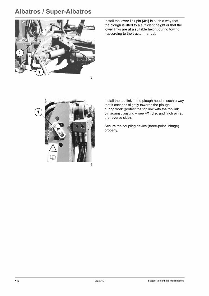
Install the lower link pin (3/1) in such a way that the plough is lifted to a sufficient height or that the lower links are at a suitable height during towing - according to the tractor manual.
Install the top link in the plough head in such a way that it ascends slightly towards the plough during work (protect the top link with the top link pin against twisting – see 4/1; disc and linch pin at the reverse side).
Secure the coupling device (three-point linkage) properly.
1705.2012
Albatros / Super-Albatros
Subject to technical modifications
1
5
2
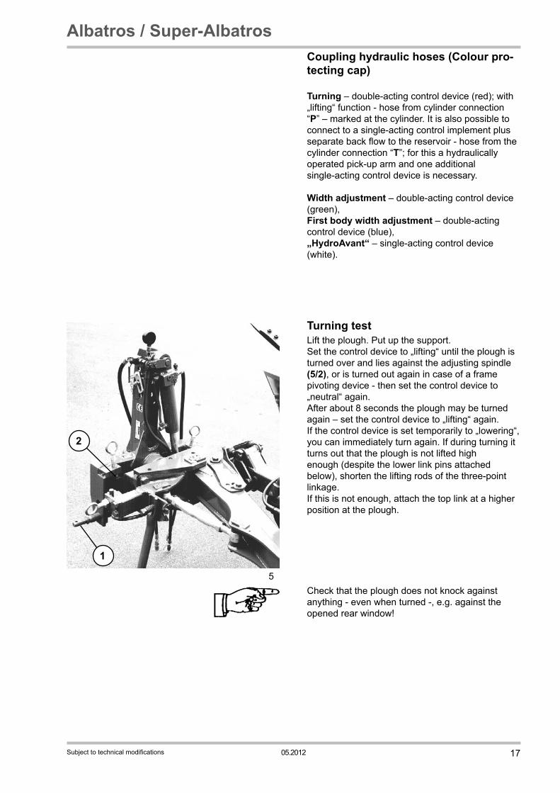
Coupling hydraulic hoses (Colour pro-tecting cap) Turning – double-acting control device (red); with „lifting“ function - hose from cylinder connection “P” – marked at the cylinder. It is also possible to connect to a single-acting control implement plus separate back flow to the reservoir - hose from the cylinder connection “T”; for this a hydraulically operated pick-up arm and one additional single-acting control device is necessary.
Width adjustment – double-acting control device (green),First body width adjustment – double-acting control device (blue),„HydroAvant“ – single-acting control device (white).
Turning testLift the plough. Put up the support. Set the control device to „lifting“ until the plough is turned over and lies against the adjusting spindle (5/2), or is turned out again in case of a frame pivoting device - then set the control device to „neutral“ again. After about 8 seconds the plough may be turned again – set the control device to „lifting“ again. If the control device is set temporarily to „lowering“, you can immediately turn again. If during turning it turns out that the plough is not lifted high enough (despite the lower link pins attached below), shorten the lifting rods of the three-point linkage. If this is not enough, attach the top link at a higher position at the plough.
Check that the plough does not knock against anything - even when turned -, e.g. against the opened rear window!
18 05.2012
Albatros / Super-Albatros
Subject to technical modifications
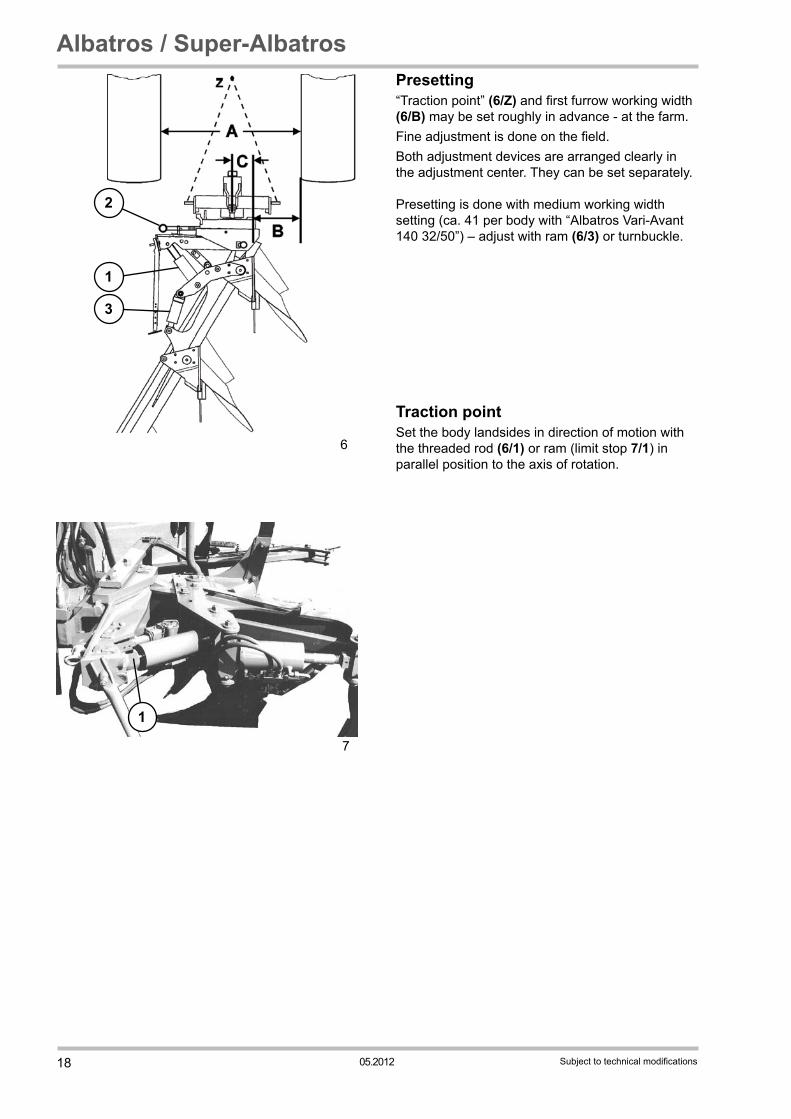
Presetting “Traction point” (6/Z) and first furrow working width (6/B) may be set roughly in advance - at the farm.Fine adjustment is done on the field.Both adjustment devices are arranged clearly in the adjustment center. They can be set separately. Presetting is done with medium working width setting (ca. 41 per body with “Albatros Vari-Avant 140 32/50”) – adjust with ram (6/3) or turnbuckle.
Traction pointSet the body landsides in direction of motion with the threaded rod (6/1) or ram (limit stop 7/1) in parallel position to the axis of rotation.
6
1
2
3
7
1
1905.2012
Albatros / Super-Albatros
Subject to technical modifications
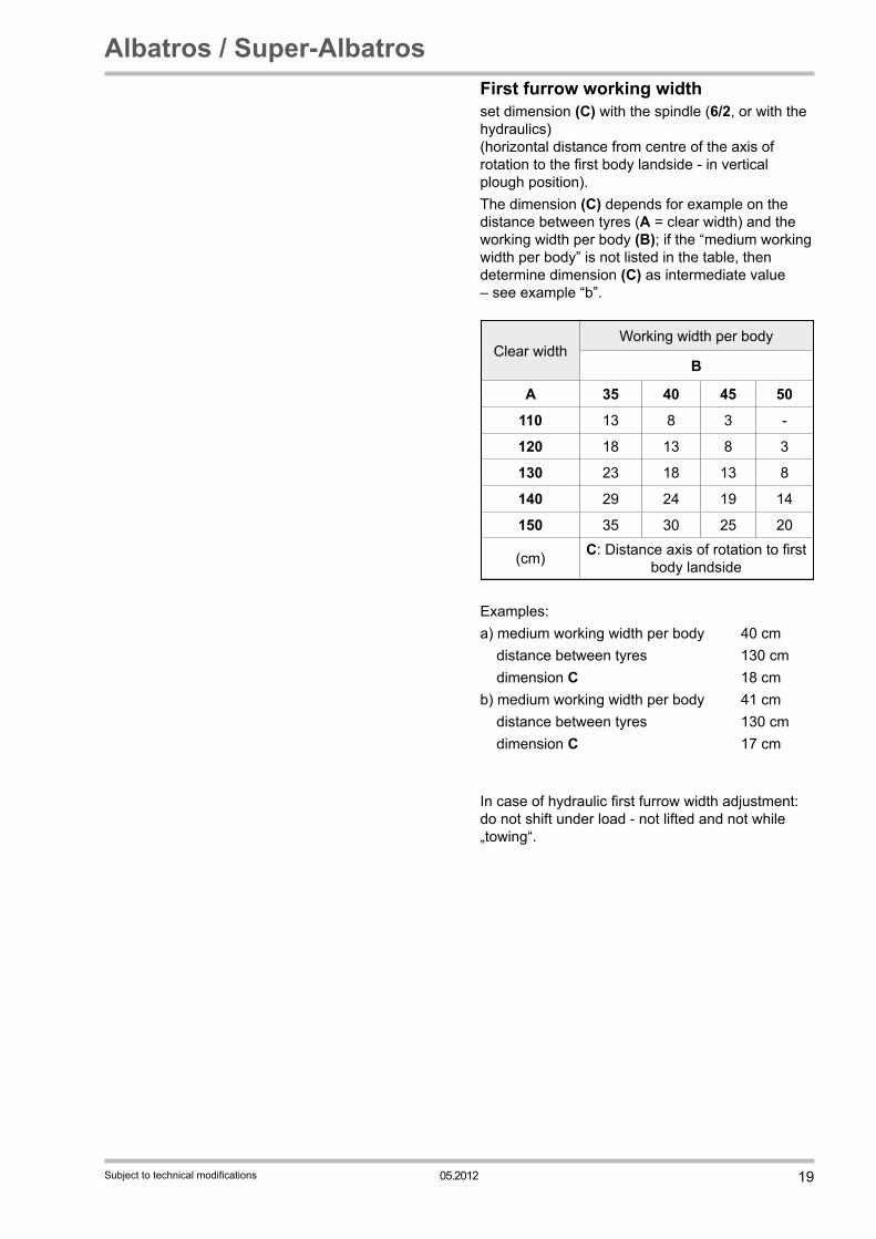
First furrow working widthset dimension (C) with the spindle (6/2, or with the hydraulics) (horizontal distance from centre of the axis of rotation to the first body landside - in vertical plough position). The dimension (C) depends for example on the distance between tyres (A = clear width) and the working width per body (B); if the “medium working width per body” is not listed in the table, then determine dimension (C) as intermediate value – see example “b”.
Clear widthWorking width per body
B
A 35 40 45 50
110 13 8 3 -
120 18 13 8 3
130 23 18 13 8
140 29 24 19 14
150 35 30 25 20
(cm) C: Distance axis of rotation to first body landside
Examples:a) medium working width per body 40 cm distance between tyres 130 cm dimension C 18 cmb) medium working width per body 41 cm distance between tyres 130 cm dimension C 17 cm In case of hydraulic first furrow width adjustment: do not shift under load - not lifted and not while „towing“.
20 05.2012
Albatros / Super-Albatros
Subject to technical modifications
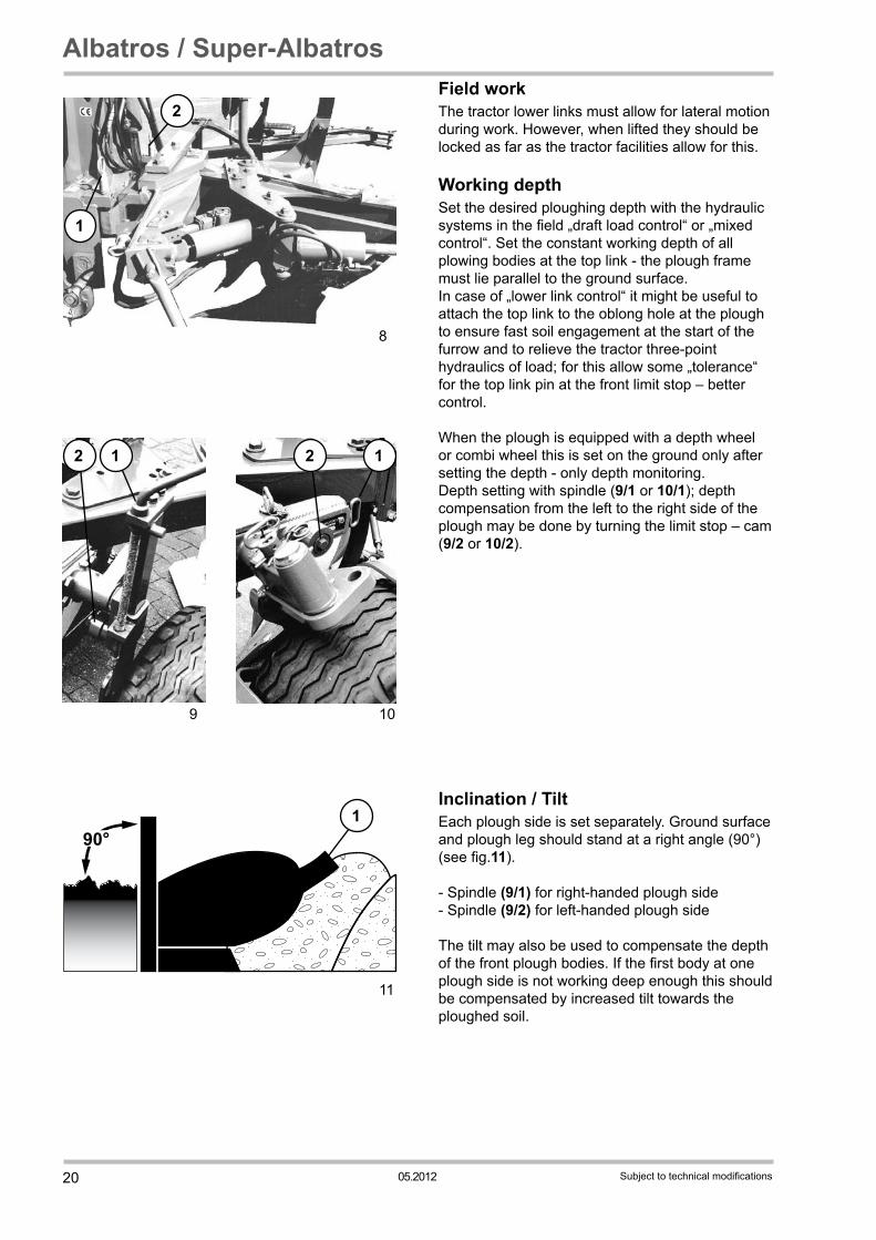
Field workThe tractor lower links must allow for lateral motion during work. However, when lifted they should be locked as far as the tractor facilities allow for this.
Working depthSet the desired ploughing depth with the hydraulic systems in the field „draft load control“ or „mixed control“. Set the constant working depth of all plowing bodies at the top link - the plough frame must lie parallel to the ground surface. In case of „lower link control“ it might be useful to attach the top link to the oblong hole at the plough to ensure fast soil engagement at the start of the furrow and to relieve the tractor three-point hydraulics of load; for this allow some „tolerance“ for the top link pin at the front limit stop – better control.
When the plough is equipped with a depth wheel or combi wheel this is set on the ground only after setting the depth - only depth monitoring. Depth setting with spindle (9/1 or 10/1); depth compensation from the left to the right side of the plough may be done by turning the limit stop – cam (9/2 or 10/2).
9
2 12
10
12
9
1
11
Inclination / TiltEach plough side is set separately. Ground surface and plough leg should stand at a right angle (90°) (see fig.11).
- Spindle (9/1) for right-handed plough side- Spindle (9/2) for left-handed plough side
The tilt may also be used to compensate the depth of the front plough bodies. If the first body at one plough side is not working deep enough this should be compensated by increased tilt towards the ploughed soil.
8
2
1

2105.2012
Albatros / Super-Albatros
Subject to technical modifications
Traction point and first furrow working widthMake any possible corrections of the traction point or adjustments of the first furrow working width ca. medium working width setting (see “Presetting”). If both settings need to be corrected: then first traction point and then width adjustment. Future adjustments of the working width of the first body resulting for example from other working depths or hillside locations have only minor effects on the traction point setting.
Traction point (lower link position): The tractor is to run in the furrow without side pull. If the laterally flexible lower links do not end up at ca. the centre of the tractor and therefore, there is side pull, this is to be corrected with a threaded rod or cylinder (6/1) (twist the limit stop 12/2 at the cylinder – wrench 12/3 – secure with key 12/4 in the groove).Threaded rod/cylinder (6/1) shorter – Three-point linkage moves to the ploughed soilThreaded rod/cylinder (6/1) longer– Three-point linkage moves to the unploughed soilIf for example the tractor is pulled to the ploughed soil at the front, then shorten the threaded rod or cylinder. Always move the cylinder to the limit stop.
First furrow working width: is to be adjusted according to the working width of the other bodies.Move the plough frame parallely with the spindle (6/2) or with the hydraulic system:Move the plough frame towards the ploughed soil– first furrow narrowerMove the plough frame towards the unploughed soil– first furrow wider.
In case of hydraulic first furrow width adjustment: do not shift under load - not lifted and not while „towing“.
12
3
2
4
6
1
2
3

22 05.2012
Albatros / Super-Albatros
Subject to technical modifications
Working width adjustment After the basic adjustment, (traction point, first furrow width) the desired working width may be set with the turnbuckle or ram (6/3); Hydraulic system: in small steps during motion.Traction point and first furrow working width are adapted automatically.Turnbuckle/cylinder longer – smaller working widthTurnbuckle/cylinder shorter – wider working width
Levelling bars (if available, 11/1)Set all equally; not too deep, so that they do not „stand“ in the turned soil.
1
11
6
1
2
3
2305.2012
Albatros / Super-Albatros
Subject to technical modifications
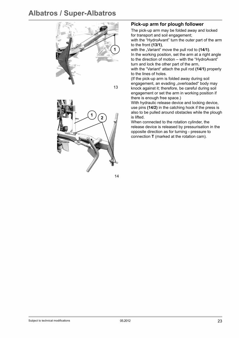
Pick-up arm for plough followerThe pick-up arm may be folded away and locked for transport and soil engagement; with the “HydroAvant” turn the outer part of the arm to the front (13/1),with the „Variant“ move the pull rod to (14/1).In the working position, set the arm at a right angle to the direction of motion – with the “HydroAvant” turn and lock the other part of the arm, with the “Variant“ attach the pull rod (14/1) properly to the lines of holes.(If the pick-up arm is folded away during soil engagement, an evading „overloaded“ body may knock against it; therefore, be careful during soil engagement or set the arm in working position if there is enough free space.)With hydraulic release device and locking device, use pins (14/2) in the catching hook if the press is also to be pulled around obstacles while the plough is lifted.When connected to the rotation cylinder, the release device is released by pressurisation in the opposite direction as for turning - pressure to connection T (marked at the rotation cam).
13
1
14
1 2
24 05.2012
Albatros / Super-Albatros
Subject to technical modifications
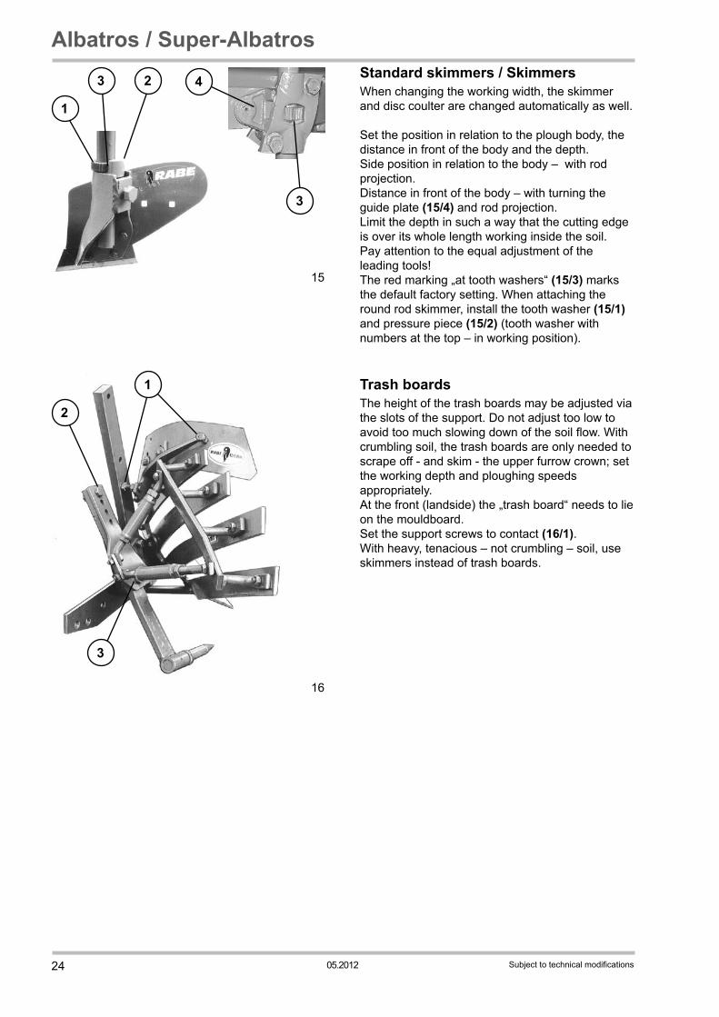
Standard skimmers / SkimmersWhen changing the working width, the skimmer and disc coulter are changed automatically as well.
Set the position in relation to the plough body, the distance in front of the body and the depth.Side position in relation to the body – with rod projection.Distance in front of the body – with turning the guide plate (15/4) and rod projection.Limit the depth in such a way that the cutting edge is over its whole length working inside the soil.Pay attention to the equal adjustment of the leading tools!The red marking „at tooth washers“ (15/3) marks the default factory setting. When attaching the round rod skimmer, install the tooth washer (15/1) and pressure piece (15/2) (tooth washer with numbers at the top – in working position).
Trash boardsThe height of the trash boards may be adjusted via the slots of the support. Do not adjust too low to avoid too much slowing down of the soil flow. With crumbling soil, the trash boards are only needed to scrape off - and skim - the upper furrow crown; set the working depth and ploughing speeds appropriately. At the front (landside) the „trash board“ needs to lie on the mouldboard. Set the support screws to contact (16/1). With heavy, tenacious – not crumbling – soil, use skimmers instead of trash boards.
1
3 2
3
4
15
2
3
1
16

2505.2012
Albatros / Super-Albatros
Subject to technical modifications
Disc coulter Installable with “HydroAvant” in front of all bodies, with “Variant” only in front of the last bodies. Limit the depth in such a way that between the disc bearing housing and the ground is not more than ca. 5cm of free space – turn tooth washer (17/1). „Landside“ distance to the body ca. 2 - 4 cm; may be adjusted by turning the arms: “Variant” – loosen screws (18/2 = centre of rotation) and (18/2) (tighten with 410 Nm). Limit side swing with adjusting ring (17/2); take care that the disc coulter can adjust in direction of motion.If the plough is transported in horizontal position - with combi wheel - the adjusting rings (17/2) must be tightened very well.
2
3
1
16
Subsoil decompactor Decompactor depth is adjustable (16/2).Overload protection: shear bolt M 16x50-4.6 (16/3).To set the plough down, swing the decompactor to the back – remove the shear bolt.
18
12
17
2 1
ca. 5 cm
ca. 2-4 cm

26 05.2012
Albatros / Super-Albatros
Subject to technical modifications
Plough leg overload protection Shear bolt (19/1) – installed also with „stone protection” (20/1) – bolt head always at plough leg side.After installing a new shear bolt, tighten the other plough leg bolts as well (19/2 bzw. 20/2).
Tightening torques plough leg bolts - Nm
Shear bolt/pivot bolt
„Normal plough“ „Stone protection“315 / 640 225 / 460
Use only original shear bolts! (see spare parts list). Danger of crunching when swivelling back the „triggered“ body. Approach the plough body only from the back - the respective plough side points downwards.If the swivelled out body is „blocked“, loosen the leg pivot bolt slightly.– do use suitable tools (19/3), e.g. RABE special wrenches and gloves! This does also apply to console bolts!
Important: Pay attention to the tightening torques!
19
123
20
2
1
2705.2012
Albatros / Super-Albatros
Subject to technical modifications
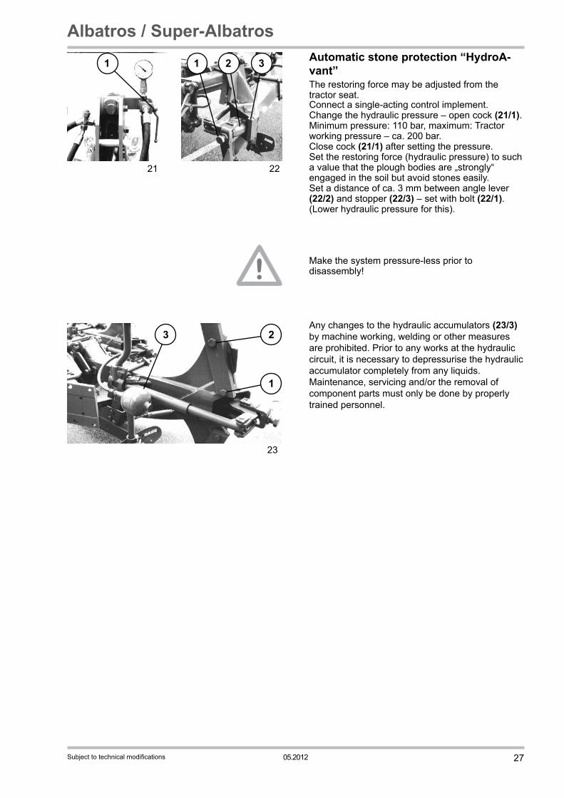
Automatic stone protection “HydroA-vant”The restoring force may be adjusted from the tractor seat.
21
1
22
1 2 3
Make the system pressure-less prior to disassembly!
Any changes to the hydraulic accumulators (23/3) by machine working, welding or other measures are prohibited. Prior to any works at the hydraulic circuit, it is necessary to depressurise the hydraulic accumulator completely from any liquids. Maintenance, servicing and/or the removal of component parts must only be done by properly trained personnel.
Connect a single-acting control implement. Change the hydraulic pressure – open cock (21/1).Minimum pressure: 110 bar, maximum: Tractor working pressure – ca. 200 bar. Close cock (21/1) after setting the pressure. Set the restoring force (hydraulic pressure) to such a value that the plough bodies are „strongly“ engaged in the soil but avoid stones easily. Set a distance of ca. 3 mm between angle lever (22/2) and stopper (22/3) – set with bolt (22/1). (Lower hydraulic pressure for this).
23
2
1
3
28 05.2012
Albatros / Super-Albatros
Subject to technical modifications
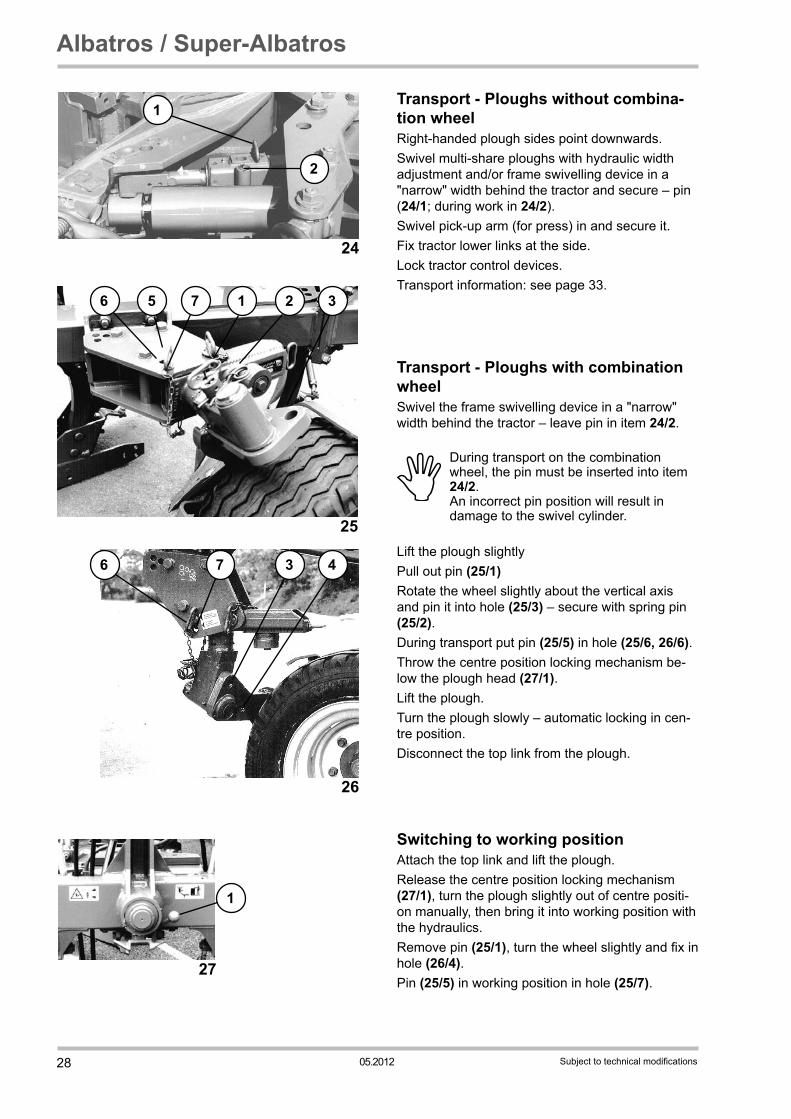
Transport - Ploughs without combina-tion wheelRight-handed plough sides point downwards.Swivel multi-share ploughs with hydraulic width adjustment and/or frame swivelling device in a "narrow" width behind the tractor and secure – pin (24/1; during work in 24/2).Swivel pick-up arm (for press) in and secure it.Fix tractor lower links at the side.Lock tractor control devices.Transport information: see page 33.
Transport - Ploughs with combination wheelSwivel the frame swivelling device in a "narrow" width behind the tractor – leave pin in item 24/2.
During transport on the combination wheel, the pin must be inserted into item 24/2.
An incorrect pin position will result in damage to the swivel cylinder.
Lift the plough slightly Pull out pin (25/1) Rotate the wheel slightly about the vertical axis and pin it into hole (25/3) – secure with spring pin (25/2). During transport put pin (25/5) in hole (25/6, 26/6).Throw the centre position locking mechanism be-low the plough head (27/1).Lift the plough. Turn the plough slowly – automatic locking in cen-tre position.Disconnect the top link from the plough.
Switching to working positionAttach the top link and lift the plough.Release the centre position locking mechanism (27/1), turn the plough slightly out of centre positi-on manually, then bring it into working position with the hydraulics.Remove pin (25/1), turn the wheel slightly and fix in hole (26/4).Pin (25/5) in working position in hole (25/7).
25
56 7 2 31
26
6 7 3 4
27
1
24
1
2

2905.2012
Albatros / Super-Albatros
Subject to technical modifications
2
3
1
16
Setting down the ploughSet the plough on the right-handed bodies - and support.Pay attention to a secure position! Set support length appropriately.Make hydraulic hoses pressure-less prior to uncoupling.Protect hydraulic coupling plug against dirt.Lubricate all slide faces.Loosen shear bolt (16/3) of subsoil decompactors and swivel decompactor to the back.

30 05.2012
Albatros / Super-Albatros
Subject to technical modifications
MaintenanceWhen working at the mounted implement, switch off motor and take out ignition key! Do not work at the lifted implement! – Support lifted implements additionally against involuntary lowering!Prior to works at the hydraulic system, lower the implement and depressurise the system! Dispose of hydraulic oil properly. Retighten all screws after first use (ca. 8 hours), then check tightness regularly – use torque wrench!Tightening torques:Tighten bolts at mouldboards with 80 Nm – also at the slatted body,lower link pins: Albatros – 1600 Nm Super-Albatros – 2400 Nm
Plough leg bolts: see table page 26. When trash boards are used, take care that the support bolts have contact (16/1). Lubricate all bearings with lubricating nipples regularly with multipurpose grease on lithium basis: e.g. at the turning, swivelling and width adjustment ram, turning axis, adjusting spindle (28/2), guide bards (28/1), spindle bearing (28/3), frame bolt (28/4), console and push rod bearing (28/4, 28/5), swivelling limit (28/6), bearing bolt of hydraulic pick-up arm, disc coulters, depth wheel (combi wheel) including holder, lubricate the bearings of the stone protection daily if you work in stony soil (HydroAvant). Check and readjust the wheel bearing, disc coulter bearing and turning axis bearing.
3
2
1
4
5
628

3105.2012
Albatros / Super-Albatros
Subject to technical modifications
The swivel axis of the combi wheel (29/1) may be readjusted – crown nut – control of the swivelling speed during „turning“.Oil joints and keep spindles running. Check hydraulic hoses regularly and replace if damaged or embrittled (spare parts list). Hoses are subject to natural aging, the time of usage should not exceed 5-6 years.When water jet cleaning (especially with high pressure) do not aim directly on bearings.Preserve all slide faces at the shut-down implement with an anticorrosion agent and all piston rods with acid-free grease. Repair defects in the paintwork. Replace wear parts in time; Replace shares and landsides before the frog (share support/side plate) starts to wear.First turn the point of shares with reversible points and then put it in front.Pre-tighten new mouldboards at the turnbuckle with2 turns (replace defective shims – see spare parts list).
Use only original RABE parts and original bolts!
Tyre air pressure: Depth wheel – 2,5 bar Combi wheel – 3,75 bar
291

32 05.2012
Albatros / Super-Albatros
Subject to technical modifications
Residual dangers
Danger areas NoteCrunching point adjusting spindle Explanation symbol
Overturning Operating instructions proper coupling/uncoupling
Falling down of the skimmers after
loosening the adjusting screw
Operating instructions skimmer
Falling down of the disc coulter after loosening
the adjusting screw
Operating instructions disc coulter
Hurling out of the stone protection
Operating instructions stone protection
Worn out strips, breast boards, countersunk
screws
Notes in the operating instructions on sharp edges
caused by wear and tearSubsoil decompactor
transported in half-turned position
Notes in the operating instructions on reverse
assembly.
Setting down with subsoil decompactors
Notes in the operating instructions on setting down
with folded in subsoil decompactors

3305.2012
Albatros / Super-Albatros
Subject to technical modifications
Caution / Transport Turn implement to „transport position“; check suitability for transport. Riding on the implement and staying in danger area are prohibited.Adapt transport speed to the street and way conditions; Maximum speed for transport with combi wheel 25 km/h (= mounted implement). Take care in turns: the implement veers out!The provisions of the Road Traffic Licensing Regulations must be complied with. According to the provisions of the Road Traffic Licensing Regulations, the operator is responsible for the roadworthy connection of tractor and implement when driving on public roads and ways.Working tools must not interfere with the safe driving of the tractor combination. The admissible tractor axle loads, total weights and the wheel load capacity (depending on speed and air pressure) must not be exceeded with the mounted implement. The front axle load must be at least 20% of the empty vehicle weight to ensure steering safety. The admissible transport width is 3 m. An exemption is necessary for wide implements. No parts may protrude from the outline of the implement in such a way that they constitute an avoidable danger (section 32 of the German Road Traffic Licensing Regulations). If protruding parts cannot be avoided they must be covered and marked. Security devices are also necessary for marking the implement outline as well as for rear protection – e.g. red/white striped warning signs 423 x 423 mm.

34 05.2012
Albatros / Super-Albatros
Subject to technical modifications
Lighting devices are necessary if the implements conceal tractor lights or if the visibility is low due to the weather conditions: e.g. to the front and back, if the implement protrudes at the side more than 40 cm over the lighting device of the tractor or for rear protection if there is a distance of more than 1m between the tractor tail lamp and the implement end. Implements with transport wheel (combi wheel – “semi-mounted implement”) must be driven with red rear reflectors, yellow side reflectors and always with lighting – also during daytime (side marker lamps if the implement protrudes at the side more than 400 mm over the tractor lights). We recommend to purchase warn signs and lighting devices directly from the vendor. For lighting devices according to DIN 11027, RABE does also sell mounting profiles that may be installed later on.


Grégoire-Besson GmbH Am Rabewerk 1
D-49152 Bad Essen
Germany
Phone: +49(0) 5472-7710
Fax: +49(0) 5472-771100
www.rabe-agri.eu
Order number 9900.00.05EN04Edition 05.2012Version 04
LanguageEN
Translation of the original operating instructions DE
Obtained from:
on:(Dealer stamp)