SunStat Pro 5. Programmable Thermostat Model...
4
5 sensor 2. Installation Remove the Thermostat Face 1. Remove the thermostat Front Module from the Power Module by opening the door and loosening the screw. 2. 2. Pull outward near the bottom on the Front Module and lift off. Be careful not to bend or damage the 14-pin electrical connector on the back of the Front Module. Prepare the Wiring 1. Find a location for your thermostat. It is suitable for indoor use only, on insulated or uninsulated walls. Locate it about 4 1 ⁄2 feet to 5 feet above the floor on an inside wall. Make sure it is well ventilated and not located in a confined space such as a small closet or cabinet. Avoid placing it near other heat sources such as hot-water piping, heat duct, wall-mount lighting, and direct sunlight to help prevent adversely affecting the thermostat. 2. Turn off the power to the floor warming system at the main circuit panel before doing any electrical work. 3. A qualified electrician should run a dedicated circuit from the main circuit panel to the thermostat location. 4. If a dedicated circuit is not possible, you may tap from another circuit in the room. Make sure there is enough load capacity (amps) to handle the addition of your floor warming system, and that it is NOT wired in series with any other Owner’s Manual Your new SunStat Pro thermostat is designed to control the voltage to either a 120VAC or 240VAC resistive floor warming system. Please follow this manual for complete installation and operation instructions. If you have any questions or comments, try calling Technical Support at 1-888-432-8932. CAUTION: Make sure you are qualified and are familiar with house wiring. This is a line voltage device that could cause serious injury or damage if improperly installed. Connect Wires 1. Match and connect the two wires marked “LINE1” and “LINE2” to the power supply wires using the wire nuts provided. 2. Gently tug on the wires to make sure they are secure, otherwise a wire could loosen and cause failure. 3. Overwrap the wire nuts with electrical tape to better secure them to the wires. 4. Match and connect the two wires marked “LOAD1” and “LOAD2” to the floor warming system lead wires and secure these wires the same way. 5. Connect the house ground wire to the green or bare lead wire(s) of your floor warming system. 6. Insert the ends of the floor sensor wire into the “SENSOR” terminals (1 and 2) and tighten the screws. There is no polarity, so it does not matter which wire end goes into which terminal. CAUTION: Before continuing, make sure your power supply voltage matches the voltage rating of your floor warming system. Connecting 240V to a 120V floor warm- ing system will cause overheating and damage to the system and may damage the control, other wiring, floor coverings, etc. Remote Control 1. If you want to connect your thermostat to a remote control device, such as a home automation system, first make sure that the remote device has a “dry contact, normally open” output (an un-energized switch, such as the contacts on a relay). Many home automation systems come with such an output that opens or closes at specified times. 2. Pull 2-conductor wire, size 18- to 24-guage, through the wall from the remote device, into this electrical box. 3. Connect the wire ends into the “SETBACK” terminals (5 and 6) and tighten the screws (no polarity). SunStat Relays 1. If you want to use your thermostat to drive a SunStat Relay(s) (ask your dealer about this convenient way to control larger systems with one thermostat), first read and follow the instructions for the SunStat Relay thoroughly. 2. Pull 2-conductor wire, size 18- to 24-gauge, through the wall from the SunStat Relay, into this electrical box. This wire may be up to 100 feet (30 m) in length from the thermostat to the last SunStat Relay installed. 3. Connect the wire ends into the “RELOUT” terminals (3 and 4) and tighten the screws(Observe polarity of the wires when connecting to the SunStat Relay). Mount the Thermostat 1. Carefully fold and press the wires back into the electrical box. Do not use the thermostat to push them in, as this may cause connections to loosen and possible failure. 2. Secure the thermostat Power Module into the box with the mounting screws provided. 3. Carefully align the Front Module with the Power Module to avoid bending any of the pins on the Front Module while snapping them together. 4. Tighten the screw. 5. Switch on the power at the main circuit panel. NOTE to contractors: After installing the thermostat, be sure to: a. Do a Quick Setup (section 3), b. Temporarily override the setpoint SunStat Pro Programmable Thermostat Model 500670 1-4 from power supply to floor warming system 1. Preparation 1. Unpack your thermostat and make sure everything is in good condition: • Thermostat • Floor sensor • Small screwdriver • Mounting screws • Wire nuts for wiring connections If any parts are missing or damaged, contact the store where you purchased this thermostat. Do not install a damaged part. 2. Gather the following tools and supplies: •Phillips screwdriver, hole saw •Wire strippers, “fish tape”, other electrical tools •Electrical box for thermostat: a. If you are connecting to power leads from only 1 or 2 floor warming systems, you may use a single-gang, 3 1 ⁄2 inch deep box. b. If you are connecting to power leads from 3 floor warming systems, use a 4x4x2 1 ⁄8 inch or deeper box (not a 2-gang box) when your wall studs are still exposed. Install a single-gang “mud-ring” cover on the box before installing drywall materials. c. For more than 3 floor warming systems or other layouts, you may need to install a junction box to connect the power leads together. Then use house wire to connect between the junction box and the thermostat electrical box. See the installation instructions for your floor warming system for more information. ALWAYS: Wire all circuits as Class 1, Electric Light and Power Circuits. ALWAYS: Wire all circuits with insulation rated 600V minimum. ALWAYS: Mount this control only to a grounded metallic box or a nonmetallic box. ALWAYS: Use power supply wires suitable for at least 90°C. CAUTION: High voltage – disconnect power supply before servicing. CAUTION: The GFCI in this control does not protect against shock if both bare conductors are touched at the same time. device, including other GFCIs. 5. The circuit breaker in the main circuit panel should be 15 amps maximum for a floor warming system totaling 12 amps or less. For larger systems up to 15 amps, use a 20 amp maximum circuit breaker. Never exceed 15 amps on this thermostat. You may consider using an arc-fault (AFCI) type circuit breaker for additional protection. 6. Mount the electrical box. 7. Pull the power supply wiring into this box, leaving about 6 inches of wire. 8. Pull the floor sensor wire and the power lead wires from your floor warming system up the wall, into this box. Refer to your floor warming system installation instructions for placement of the floor sensor tip into the floor area. Note: The sensor wires should not be run in the same conduit as line voltage wires to avoid possible interference. If the sensor lead wires are not long enough, they may be extended an additional 15 feet (4.5 m) using minimum 20-gauge 2-conductor wire or up to 50 feet (15 m) using shielded wire. power module front module
Transcript of SunStat Pro 5. Programmable Thermostat Model...
5
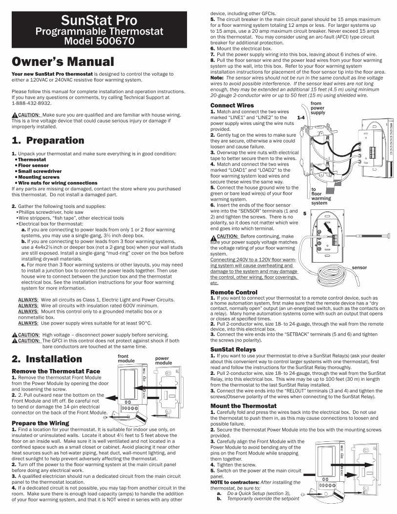
sensor
2. InstallationRemove the Thermostat Face1. Remove the thermostat Front Module from the Power Module by opening the door and loosening the screw.2. 2. Pull outward near the bottom on the Front Module and lift off. Be careful not to bend or damage the 14-pin electrical connector on the back of the Front Module.
Prepare the Wiring1. Find a location for your thermostat. It is suitable for indoor use only, on insulated or uninsulated walls. Locate it about 41⁄2 feet to 5 feet above the floor on an inside wall. Make sure it is well ventilated and not located in a confined space such as a small closet or cabinet. Avoid placing it near other heat sources such as hot-water piping, heat duct, wall-mount lighting, and direct sunlight to help prevent adversely affecting the thermostat.2. Turn off the power to the floor warming system at the main circuit panel before doing any electrical work.3. A qualified electrician should run a dedicated circuit from the main circuit panel to the thermostat location.4. If a dedicated circuit is not possible, you may tap from another circuit in the room. Make sure there is enough load capacity (amps) to handle the addition of your floor warming system, and that it is NOT wired in series with any other
Owner’s ManualYour new SunStat Pro thermostat is designed to control the voltage to either a 120VAC or 240VAC resistive floor warming system.
Please follow this manual for complete installation and operation instructions. If you have any questions or comments, try calling Technical Support at 1-888-432-8932.
CAUTION: Make sure you are qualified and are familiar with house wiring. This is a line voltage device that could cause serious injury or damage if improperly installed.
Connect Wires1. Match and connect the two wires marked “LINE1” and “LINE2” to the power supply wires using the wire nuts provided.2. Gently tug on the wires to make sure they are secure, otherwise a wire could loosen and cause failure.3. Overwrap the wire nuts with electrical tape to better secure them to the wires.4. Match and connect the two wires marked “LOAD1” and “LOAD2” to the floor warming system lead wires and secure these wires the same way.5. Connect the house ground wire to the green or bare lead wire(s) of your floor warming system.6. Insert the ends of the floor sensor wire into the “SENSOR” terminals (1 and 2) and tighten the screws. There is no polarity, so it does not matter which wire end goes into which terminal. CAUTION: Before continuing, make sure your power supply voltage matches the voltage rating of your floor warming system. Connecting 240V to a 120V floor warm-ing system will cause overheating and damage to the system and may damage the control, other wiring, floor coverings, etc. Remote Control1. If you want to connect your thermostat to a remote control device, such as a home automation system, first make sure that the remote device has a “dry contact, normally open” output (an un-energized switch, such as the contacts on a relay). Many home automation systems come with such an output that opens or closes at specified times.2. Pull 2-conductor wire, size 18- to 24-guage, through the wall from the remote device, into this electrical box.3. Connect the wire ends into the “SETBACK” terminals (5 and 6) and tighten the screws (no polarity). SunStat Relays1. If you want to use your thermostat to drive a SunStat Relay(s) (ask your dealer about this convenient way to control larger systems with one thermostat), first read and follow the instructions for the SunStat Relay thoroughly.2. Pull 2-conductor wire, size 18- to 24-gauge, through the wall from the SunStat Relay, into this electrical box. This wire may be up to 100 feet (30 m) in length from the thermostat to the last SunStat Relay installed.3. Connect the wire ends into the “RELOUT” terminals (3 and 4) and tighten the screws(Observe polarity of the wires when connecting to the SunStat Relay). Mount the Thermostat1. Carefully fold and press the wires back into the electrical box. Do not use the thermostat to push them in, as this may cause connections to loosen and possible failure.2. Secure the thermostat Power Module into the box with the mounting screws provided.3. Carefully align the Front Module with the Power Module to avoid bending any of the pins on the Front Module while snapping them together. 4. Tighten the screw.5. Switch on the power at the main circuit panel.NOTE to contractors: After installing the thermostat, be sure to: a. Do a Quick Setup (section 3), b. Temporarily override the setpoint
SunStat ProProgrammable Thermostat
Model 500670
1-4
from power supply
tofloor warming system
1. Preparation1. Unpack your thermostat and make sure everything is in good condition:•Thermostat•Floor sensor•Small screwdriver•Mounting screws•Wire nuts for wiring connections
If any parts are missing or damaged, contact the store where you purchased this thermostat. Do not install a damaged part.
2. Gather the following tools and supplies: •Phillips screwdriver, hole saw •Wire strippers, “fish tape”, other electrical tools •Electrical box for thermostat: a. If you are connecting to power leads from only 1 or 2 floor warming systems, you may use a single-gang, 31⁄2 inch deep box. b. If you are connecting to power leads from 3 floor warming systems, use a 4x4x21⁄8 inch or deeper box (not a 2-gang box) when your wall studs are still exposed. Install a single-gang “mud-ring” cover on the box before installing drywall materials. c. For more than 3 floor warming systems or other layouts, you may need to install a junction box to connect the power leads together. Then use house wire to connect between the junction box and the thermostat electrical box. See the installation instructions for your floor warming system for more information.
ALWAYS: Wire all circuits as Class 1, Electric Light and Power Circuits. ALWAYS: Wire all circuits with insulation rated 600V minimum. ALWAYS: Mount this control only to a grounded metallic box or a nonmetallic box. ALWAYS: Use power supply wires suitable for at least 90°C. CAUTION: High voltage – disconnect power supply before servicing. CAUTION: The GFCI in this control does not protect against shock if both
bare conductors are touched at the same time.
device, including other GFCIs.5. The circuit breaker in the main circuit panel should be 15 amps maximum for a floor warming system totaling 12 amps or less. For larger systems up to 15 amps, use a 20 amp maximum circuit breaker. Never exceed 15 amps on this thermostat. You may consider using an arc-fault (AFCI) type circuit breaker for additional protection.6. Mount the electrical box. 7. Pull the power supply wiring into this box, leaving about 6 inches of wire.8. Pull the floor sensor wire and the power lead wires from your floor warming system up the wall, into this box. Refer to your floor warming system installation instructions for placement of the floor sensor tip into the floor area.Note: The sensor wires should not be run in the same conduit as line voltage wires to avoid possible interference. If the sensor lead wires are not long enough, they may be extended an additional 15 feet (4.5 m) using minimum 20-gauge 2-conductor wire or up to 50 feet (15 m) using shielded wire.
power module
front module

3. Press the HOLD/RETURN button or wait 15 seconds and the thermostat will return to the normal operating mode, saving your selection. The thermostat will now display a P1, P2, P3, or P4 at the bottom right.
3. Quick SetupOn/Off SwitchYour thermostat should be turned off when it is first installed. The display will show OFF and the time and day.1. Slide the on/off switch to the upper position, turning the thermostat on. The display will show the time and day, temperatures, and other information.2. To turn the thermostat off anytime, slide the on/off switch to the lower position. No heating will occur and all programming is retained.
Change Format Between °F / 12-hour and °C / 24-hourYour thermostat is factory set to operate in either °F / 12 hour format or °C / 24 hour (military time) format. If needed, you may change this at any time as follows:1. Press the OPTIONS button and hold for 1 second. An °F and 12h will show on the display.2. Press the down or up button to toggle to °C and 24h.3. Press the HOLD/RETURN button to return to the normal operating mode.
Set the Current Time and Day1. Press the DAY/TIME button and hold for 1 second. The hour should be blinking.2. Press the down or up button to adjust the hour, and AM/PM if using the 12-hour clock format.3. Press the DAY/TIME button briefly. The minutes should be blinking.4. Press the down or up button to adjust the minutes.5. Press the DAY/TIME button briefly. The day should be blinking.6. Press the down or up button to adjust the day.7. Press the HOLD/RETURN button or wait 15 seconds and the thermostat will return to the normal operating mode, saving your settings.
MO
SET TEMP
FLOORCYCLE
MA
°F
Customized Program Schedule (User)To customize the program shedule to meet your needs, follow these steps:
1. Press the PROGRAM button and hold for 1 second. Pro and U1, P1, P2, P3, or P4 will show on the display.2. Press the down or up button to select U1.3. Press the PROGRAM button briefly. CYCLE 1 and MO through FR will show on the display. The hour should be blinking. 4. Press the down or up button to adjust the hour.5. Press the PROGRAM button briefly. The minutes should be blinking.6. Press the down or up button to adjust the minutes.7. Press the PROGRAM button briefly. The setpoint temperature should be blinking.8. Press the down or up button to adjust the setpoint temperature. Note: A good rule of thumb is to adjust this about 5 to 8°F (3 to 5 °C) lower during cycles when you are away to help reduce energy use. If you set the “away” cycles too low, it will take much longer to raise the temperature again and may result in unsatisfying performance. Note: Some wood and laminate floor manufacturers recommend a maximum of 82 to 84°F (27° to 28°C). Check with manufacturer.9. Press the PROGRAM button briefly to move to the next cycle number.10. Repeat Steps 3 through 7 to adjust the remaining cycle times and setpoint temperatures MO through FR, and for the other days of the week.Note: Cycle 4 must never be set to a point past 11:59 pm. If cycle 4 is set to midnight or later, the thermostat may not cycle properly.11. When you finish, or at any time during these adjustments, press the HOLD/RETURN button or wait 30 seconds and the thermostat will return to the normal operating mode. Your adjustments will be saved.Note: The display in normal operating mode will not show a “U1” indicating “User” schedule. Also, all schedule adjustments are saved in memory and will not be lost during a brief power failure.Note: If you only want to use two cycles during a day, clear the other cycles by reducing their temperature below 40°F (4.5°C) to show (---). Cycle 4 must always be used for the system to cycle properly.To use these cycles again, adjust their time and temperature.
on/off
MO
MA
SET TEMP
LIMITFLOOR
°F
MO
°C
AIR
SET TEMP
SET BACK
LIMITFLOOR
USAGE
CYCLE
MAMP
MAMP
°C
°F
°C
°F
TU WE TH FR SA SU
HOLD
GFCITRIP
HEATING
°F
P1P2P3P4
LOCK
MO
MA
HEATING
MO
SET TEMP
CYCLE
MA
°F
HOLD
USAGE
MO
CYCLE
MA
°F
TU WE TH FR MO
CYCLE
MA
°F
SET BACK
FLOOR
FLOOR
MO
CYCLE
MA
°F
FLOOR
Use the Factory Programmed “User” ScheduleIf you want to begin using your thermostat now without making any changes to the factory set programming schedule, you may skip to section “5 Operation”. It will operate in the “User” Schedule (U1), pre-programmed as follows, and can be customized later to your needs (see section “4 Additional Setups”):
4. Additional SetupsLifestyle Program Schedules (Presets)There are convenient schedules already set up to meet typical lifestyles. If you see a schedule P1 through P4 you like, select one as follows:
1. Press the PROGRAM button and hold for 1 second. Pro and U1, P1, P2, P3, or P4 will show on the display. 2. Press the down or up button briefly to select P1, P2, P3, or P4. These schedules are not able to be modified, and are as follows:
MO
MA
SET TEMP
LIMITFLOOR
°F
MO
°C
AIR
SET TEMP
SET BACK
LIMITFLOOR
USAGE
CYCLE
MAMP
MAMP
°C
°F
°C
°F
TU WE TH FR SA SU
HOLD
GFCITRIP
HEATING
°F
P1P2P3P4
LOCK
MO
MA
HEATING
MO
SET TEMP
CYCLE
MA
°F
HOLD
USAGE
MO
CYCLE
MA
°F
TU WE TH FR MO
CYCLE
MA
°F
SET BACK
FLOOR
FLOOR
MO
CYCLE
MA
°F
FLOOR
MO
MA
SET TEMP
LIMITFLOOR
°F
MO
°C
AIR
SET TEMP
SET BACK
LIMITFLOOR
USAGE
CYCLE
MAMP
MAMP
°C
°F
°C
°F
TU WE TH FR SA SU
HOLD
GFCITRIP
HEATING
°F
P1P2P3P4
LOCK
MO
MA
HEATING
MO
SET TEMP
CYCLE
MA
°F
HOLD
USAGE
MO
CYCLE
MA
°F
TU WE TH FR MO
CYCLE
MA
°F
SET BACK
FLOOR
FLOOR
MO
CYCLE
MA
°F
FLOOR
MO
MA
SET TEMP
LIMITFLOOR
°F
MO
°C
AIR
SET TEMP
SET BACK
LIMITFLOOR
USAGE
CYCLE
MAMP
MAMP
°C
°F
°C
°F
TU WE TH FR SA SU
HOLD
GFCITRIP
HEATING
°F
P1P2P3P4
LOCK
MO
MA
HEATING
MO
SET TEMP
CYCLE
MA
°F
HOLD
USAGE
MO
CYCLE
MA
°F
TU WE TH FR MO
CYCLE
MA
°F
SET BACK
FLOOR
FLOOR
MO
CYCLE
MA
°F
FLOOR
MO
MA
SET TEMP
LIMITFLOOR
°F
MO
°C
AIR
SET TEMP
SET BACK
LIMITFLOOR
USAGE
CYCLE
MAMP
MAMP
°C
°F
°C
°F
TU WE TH FR SA SU
HOLD
GFCITRIP
HEATING
°F
P1P2P3P4
LOCK
MO
MA
HEATING
MO
SET TEMP
CYCLE
MA
°F
HOLD
USAGE
MO
CYCLE
MA
°F
TU WE TH FR MO
CYCLE
MA
°F
SET BACK
FLOOR
FLOOR
MO
CYCLE
MA
°F
FLOOR
Cycle 1 2 3 4Mon-Fri 6:00 am 8:00 am 5:00 pm 10:00 pm
82 F 74 F 82 F 74 F Saturday 7:00 am 9:00 am 5:00 pm 11:00 pm
82 F 74 F 82 F 74 FSunday 7:00 am 9:00 am 5:00 pm 11:00 pm
82 F 74 F 82 F 74 F
U1 (User changeable)
82 F 82 F
74 F 74 F
Note: Air Sensing mode default temperatures are 70F and 62F.
Cycle 1 2 3 4Mon-Fri 5:00 am 7:00 am 5:00 pm 10:00 pm
82 F 74 F 82 F 74 F Saturday 5:00 am 9:00 am 5:00 pm 10:00 pm
82 F 74 F 82 F 74 FSunday 5:00 am 9:00 am 5:00 pm 10:00 pm
82 F 74 F 82 F 74 F
P1 (Early Riser)
Note: Air Sensing mode default temperatures are 70F and 62F.
Cycle 1 2 3 4Mon-Fri 5:00 am 8:00 am 6:00 pm 11:00 pm
82 F 74 F 82 F 74 F Saturday 6:00 am 9:00 am 5:00 pm 11:00 pm
82 F 74 F 82 F 74 FSunday 6:00 am 9:00 am 5:00 pm 11:00 pm
82 F 74 F 82 F 74 F
P2 (Longer Day)
Note: Air Sensing mode default temperatures are 70F and 62F.
Cycle 1 2 3 4Mon-Fri 6:00 am 9:00 am 6:00 pm 10:00 pm
75 F 70 F 75 F 70 F Saturday 7:00 am 10:00 am 6:00 pm 10:00 pm
75 F 70 F 75 F 70 FSunday 7:00 am 10:00 am 6:00 pm 10:00 pm
75 F 70 F 75 F 70 F
P4 (Take the chill off)
Note: Air Sensing mode default temperatures are 65F and 60F.
Cycle 1 2 3 4Mon-Fri 6:00 am 8:00 am 6:00 pm 10:00 pm
82 F 79 F 82 F 75 F Saturday 6:00 am 9:00 am 6:00 pm 10:00 pm
82 F 79 F 82 F 75 FSunday 6:00 am 9:00 am 6:00 pm 10:00 pm
82 F 79 F 82 F 75 F
P3 (At home during the day)
Note: Air Sensing mode default temperatures are 70F, 67F, and 62F.
Example
Cycle 1 2 3 4Mon-Fri --:-- --:-- 7:30 am 6:00 pm
-- F -- F 72 F 80 F
80 F 80 F
72 F
temperature to make sure it is heating for a few minutes (section 5), c. Test the GFCI (section 5).

5. OperationControlling the TemperatureYour thermostat has several ways to control your floor warming system. It is factory set to operate in the program schedule selected but this can be overridden to meet your needs.
Program ScheduleThe thermostat will operate normally in the program schedule selected.
When heat is called for, HEATING will show on the display and full power is supplied to the floor warming system. This also signals to turn on any SunStat Relays that may be connected to your thermostat.
Temporarily Overriding the Temperature
You can temporarily adjust the temperature setpoint as follows. This will hold until the next scheduled program time:
1. Press the down or up arrow button and hold for 1 second to adjust the setpoint temperature.2. Wait 5 seconds and the thermostat will return to the normal operating mode, saving your adjustment.3. To cancel this temporary override and return to the normal schedule temperature, press the HOLD/RETURN button briefly.
Hold a Selected Temperature
You can hold the current setpoint temperature indefinitely, especially useful when you are on vacation.
1. Press the HOLD/RETURN button and hold for 1 second. HOLD will show on the display and the setpoint temperature shown will be maintained until you cancel this hold.2. To cancel this hold, press the HOLD/RETURN button and hold for 1 second. HOLD will disappear from the display.3. Press Hold/Return briefly and the thermostat will return to the normal schedule temperature.
Setback
You can use the Setback button to override the current setpoint temperature. This is especially useful if you have an alternate temperature you repeatedly select when you are away.
1. Press the SETBACK button briefly. SETBACK will show on the display and its temperature. This setpoint will hold until the next scheduled program time.2. To hold this Setback temperature indefinitely, press the HOLD/RETURN button and hold for 1 second. To cancel this hold, press the HOLD/RETURN button again and hold for 1 second.3. To cancel this Setback temperature and return to the normal schedule temperature, press the SETBACK button briefly.
To change the temperature stored in the SETBACK button:
1. Press the SETBACK button and hold for 1 second. SETBACK will show on the display and its temperature should be blinking.2. Press the down or up button to adjust the temperature.3. Press the HOLD/RETURN button or wait 5 seconds and the thermostat will return to the normal operating mode, saving your adjustment.
Remote Control Override
If your thermostat was installed with Remote Control input from a home automation system (see section 2 “Installation”), this will override the thermostat when the remote control system closes its output switch or relay.SETBACK and HOLD will show on the display and it will operate in the Setback temperature indefinitely. To cancel this, the Remote Control switch or relay must be opened.
MO
MA
SET TEMP
LIMITFLOOR
°F
MO
°C
AIR
SET TEMP
SET BACK
LIMITFLOOR
USAGE
CYCLE
MAMP
MAMP
°C
°F
°C
°F
TU WE TH FR SA SU
HOLD
GFCITRIP
HEATING
°F
P1P2P3P4
LOCK
MO
MA
HEATING
MO
SET TEMP
CYCLE
MA
°F
HOLD
USAGE
MO
CYCLE
MA
°F
TU WE TH FR MO
CYCLE
MA
°F
SET BACK
FLOOR
FLOOR
MO
CYCLE
MA
°F
FLOOR
MO
MA
SET TEMP
LIMITFLOOR
°F
MO
°C
AIR
SET TEMP
SET BACK
LIMITFLOOR
USAGE
CYCLE
MAMP
MAMP
°C
°F
°C
°F
TU WE TH FR SA SU
HOLD
GFCITRIP
HEATING
°F
P1P2P3P4
LOCK
MO
MA
HEATING
MO
SET TEMP
CYCLE
MA
°F
HOLD
USAGE
MO
CYCLE
MA
°F
TU WE TH FR MO
CYCLE
MA
°F
SET BACK
FLOOR
FLOOR
MO
CYCLE
MA
°F
FLOOR
MO
MA
SET TEMP
LIMITFLOOR
°F
MO
°C
AIR
SET TEMP
SET BACK
LIMITFLOOR
USAGE
CYCLE
MAMP
MAMP
°C
°F
°C
°F
TU WE TH FR SA SU
HOLD
GFCITRIP
HEATING
°F
P1P2P3P4
LOCK
MO
MA
HEATING
MO
SET TEMP
CYCLE
MA
°F
HOLD
USAGE
MO
CYCLE
MA
°F
TU WE TH FR MO
CYCLE
MA
°F
SET BACK
FLOOR
FLOOR
MO
CYCLE
MA
°F
FLOOR
Air Sensing and Regulator ModesYour thermostat is factory set to operate based on the floor sensor temperature. This is the recommended method to properly control your floor warming system.
However, it is also possible to also operate your thermostat in either the air sensing mode or regulator mode temporarily if the floor sensor was damaged or not installed. A new floor sensor should be installed to enable operation in Floor Sense Mode as soon as possible. These modes must be used with caution to avoid overheating the floor. • Air Sensing Mode – This mode operates by an air sensor inside the thermostat. If your floor sensor is connected, you must set a Floor Limit temperature to avoid overheating the floor coverings (see Floor Limit below). Note: the internal heating in the thermostat may affect the sensor temperature. • Regulator Mode– In this mode the user selects the amount of time the floor warming system heats during a 15-minute repeating cycle. There is no temperature sensing in this mode. (see section 5 “Operation”)
If you want it to operate in the air sensing mode or regulator mode, you may change this as follows:
1. Press the OPTIONS button and hold for 1 second.2. Press the OPTIONS button again until SENS shows on the display.3. Press the down or up button to toggle this to Air or rEGu. (If using Regulator Mode, please see details for adjustment within the Regulator Mode subtopic.) 4. Press the HOLD/RETURN button to return to the normal operating mode.
Floor LimitIf you set your thermostat to operate in Air Sense Mode, the display will show the air temperature but will also monitor the floor sensor if it is connected.
To avoid possibly overheating your floor, you must set a Floor Limit temperature so it turns off the system if the floor sensor temperature exceeds this Floor Limit. Some wood and laminate floor manufacturers recommend a maximum of 82 to 84°F (27° to 28°C). Check with manufacturer. It is factory set to 99F (37C) and can be adjusted as follows:
1. Press the OPTIONS button and hold for 1 second.2. Press the OPTIONS button again until SET TEMP and FLOOR LIMIT shows on the display with the current Floor Limit temperature.3. Press the down or up button to adjust this.4. Press the HOLD/RETURN button to return to the normal operating mode.
CalibrationYour thermostat allows the ability to slightly adjust the display temperature. Normally this is not recommended nor required. However, in special circumstances this may be necessary, and can be done as follows:
1. Press the OPTIONS button and hold for 1 second.2. Press the OPTIONS button again until CAL shows on the display with the current sensor temperature and the current offset value. The offset value is factory set to zero.3. Press the down or up button to adjust this.4. Press the HOLD/RETURN button to return to the normal operating mode.
MO
MA
SET TEMP
LIMITFLOOR
°F
MO
°C
AIR
SET TEMP
SET BACK
LIMITFLOOR
USAGE
CYCLE
MAMP
MAMP
°C
°F
°C
°F
TU WE TH FR SA SU
HOLD
GFCITRIP
HEATING
°F
P1P2P3P4
LOCK
MO
MA
HEATING
MO
SET TEMP
CYCLE
MA
°F
HOLD
USAGE
MO
CYCLE
MA
°F
TU WE TH FR MO
CYCLE
MA
°F
SET BACK
FLOOR
FLOOR
MO
CYCLE
MA
°F
FLOORMO
MA
SET TEMP
LIMITFLOOR
°F
MO
°C
AIR
SET TEMP
SET BACK
LIMITFLOOR
USAGE
CYCLE
MAMP
MAMP
°C
°F
°C
°F
TU WE TH FR SA SU
HOLD
GFCITRIP
HEATING
°F
P1P2P3P4
LOCK
MO
MA
HEATING
MO
SET TEMP
CYCLE
MA
°F
HOLD
USAGE
MO
CYCLE
MA
°F
TU WE TH FR MO
CYCLE
MA
°F
SET BACK
FLOOR
FLOOR
MO
CYCLE
MA
°F
FLOOR
MO
MA
SET TEMP
LIMITFLOOR
°F
MO
°C
AIR
SET TEMP
SET BACK
LIMITFLOOR
USAGE
CYCLE
MAMP
MAMP
°C
°F
°C
°F
TU WE TH FR SA SU
HOLD
GFCITRIP
HEATING
°F
P1P2P3P4
LOCK
MO
MA
HEATING
MO
SET TEMP
CYCLE
MA
°F
HOLD
USAGE
MO
CYCLE
MA
°F
TU WE TH FR MO
CYCLE
MA
°F
SET BACK
FLOOR
FLOOR
MO
CYCLE
MA
°F
FLOOR
MO
MA
SET TEMP
LIMITFLOOR
°F
MO
°C
AIR
SET TEMP
SET BACK
LIMITFLOOR
USAGE
CYCLE
MAMP
MAMP
°C
°F
°C
°F
TU WE TH FR SA SU
HOLD
GFCITRIP
HEATING
°F
P1P2P3P4
LOCK
MO
MA
HEATING
MO
SET TEMP
CYCLE
MA
°F
HOLD
USAGE
MO
CYCLE
MA
°F
TU WE TH FR MO
CYCLE
MA
°F
SET BACK
FLOOR
FLOOR
MO
CYCLE
MA
°F
FLOOR
Resetting Factory DefaultsYour thermostat has the ability to reset all programming, settings, and usage times to the factory defaults. If you are certain you want to do this:
1. Press the OPTIONS button and hold for 1 second.2. Press the OPTIONS button again until the software version Soft 1.4 or similar shows on the display.3. Press the down and up buttons at the same time and hold for 1 second. Done and rst will show on the display. The thermostat will go through a startup mode and return to the normal operating mode.
SmartStartYour thermostat is factory set with the “SmartStart” feature turned on. The thermostat automatically determines the best time to begin heating so it reaches your setpoint temperature at the scheduled time.
If this feature is not desired, you may turn it off:
1. Press the OPTIONS button and hold for 1 second.2. Press the OPTIONS button again until SSt shows on the display.3. Press the down or up button to toggle this On or Off.4. Press the HOLD/RETURN button to return to the normal operating mode.
MO
MA
SET TEMP
LIMITFLOOR
°F
MO
°C
AIR
SET TEMP
SET BACK
LIMITFLOOR
USAGE
CYCLE
MAMP
MAMP
°C
°F
°C
°F
TU WE TH FR SA SU
HOLD
GFCITRIP
HEATING
°F
P1P2P3P4
LOCK
MO
MA
HEATING
MO
SET TEMP
CYCLE
MA
°F
HOLD
USAGE
MO
CYCLE
MA
°F
TU WE TH FR MO
CYCLE
MA
°F
SET BACK
FLOOR
FLOOR
MO
CYCLE
MA
°F
FLOOR

Lockout FeatureYour thermostat has the ability to lock out adjustment by other users. This may be useful in public locations. Only the on/off switch and the GFCI test button will then operate.
1. Press the down and up button at the same time and hold for 1 second. LOCK will show on the display.2. To cancel this lockout, the down and up button must be pressed and held for 1 second, then LOCK should disappear from the display. The thermostat will return to the normal operating mode.
Test the GFCIThere is a GFCI (Ground Fault Circuit Interrupter) inside the thermostat. It is designed to help protect people from possible electrical shock if the floor warming system has been damaged.
To make sure the GFCI is operating, test it after it is installed and once each month:
1. Make sure the thermostat is HEATING. You may need to increase the setpoint temporarily.2. Press the GFCI Test button on the side of the thermostat. GFCI TRIP should show on the display and a red light will show next to the GFCI Test button. You should also hear a click, indicating power has been removed from the floor warming system and the floor should gradually cool off. If any of these indicators fail, turn off power to the thermostat at the beaker panel. Do not continue to use. 3. To reset the GFCI, slide the On/Off switch off and back on. If the GFCI does not reset, turn the thermostat off and go to section 6 “Troubleshooting” within these instructions, or visit the Troubleshooting section of the suntouch.com web site for help.
Limited WarrantyWatts Radiant, Inc. warrants this thermostat control and sensor (the product) to be free from defects in material and workmanship for a period of two (2) years from the date of original purchase from authorized dealers. During this period, Watts Radiant, Inc. will replace the product or refund the original cost of the product at Watts Radiant’s option, without charge, if the product is proven defective in normal use. Please return the thermostat to your distributor to begin the warranty process.This limited warranty does not cover shipping costs. Nor does it cover a product subjected to misuse or accidental damage. This warranty does not cover the cost of installation, diagnosis, removal or reinstallation, or any material costs or loss of use.This limited warranty is in lieu of all other warranties, obligations, or liabilities expressed or implied by the company. In no event shall Watts Radiant, Inc. be liable for consequential or incidental damages resulting from installation of this product. Some states or provinces do not allow limitations on how long an implied warranty lasts, or the exclusion or limitation of incidental or consequential damages, so the above exclusions or limitations may not apply to you. This warranty gives you specific legal rights and you may also have other rights that vary from state to state.
7. Specifications Power Supply 120/240 VAC, 50/60 Hz Maximum Load 15 amps, resistive Maximum Power 1800 watts at 120 VAC 3600 watts at 240 VAC GFCI Class A (5 milliamp trip) Display Range 32 °F to 140 °F (0 °C to 60 °C) Setting Range 40 °F to 99 °F (4 °C to 37 °C) Accuracy ± 0.9 °F (0.5 °C) Storage Temp 0 °F to 120 °F (0 °C to 49 °C) Sensor Thermistor, 10k NTC, double-insulated Memory Programming retained indefinitely Current time and day will need re-set if power is lost more than 30 minutes. ETL Listing Control No. 3037530 Conforms to UL 873, UL 943, CSA C22.2 No.
24, and CAN/CSA C22.2 No. 144
6. TroubleshootingProblem Solution
Thermostat works but no heat from the system.
1. Check wiring connections.2. If GFCI is tripped, reset thermostat with on/off switch.3. Check resistances on floor warming system. See manual for system.
No display.
1. Check wiring connections.2. Check circuit breaker or other protection “upstream” of thermostat.3. Check the 14-pin connection on the back of the Front Module. Sometimes the pins can become misaligned when connecting the Front Module to the Power Module.4. Measure voltage between the line side wires, is it the proper voltage for this specific floor warming system?
GFCI is tripped.1. Check wiring connections.2. Reset thermostat by switching off/on.3. Check resistances on floor warming system. See manual for system.
Heating occurs at wrong times.
1. Check that the current time and schedule times are properly set to AM or PM.2. On uninsulated concrete SmartStart may start heating very early. You may turn this feature off if not desired.
Er 1 (only at startup) Floor sensor not correct type or out of range. Check floor sensor resistance.
Er 2
Floor sensor short-circuited. Turn off power at breaker and inspect sensor connections making sure very little copper is exposed out of terminal connections. 2. Reset Factory Defaults (section 4).3. Replace floor sensor.
Er 3Floor sensor not attached and thermostat in floor sense mode. Turn off power at breaker and attach sensor. Or Reset Factory Defaults (section 4).
Er 4 or Er 5 Internal air sensor is faulty. Replace thermostat or operate in floor sense mode.
Er 6Internal temperature overlimit. Make sure sunlight is not directed at the thermostat or other heat source in proximity. Otherwise, Turn off power at breaker and contact factory.
Er 7
1. Check the 14-pin connection on the back of the Front Module. Sometimes the pins can become misaligned when connecting the Front Module to the Power Module.2. “End-of-life” indication. GFCI will no longer function correctly or safely. Reset circuit breaker, otherwise replace thermostat.
UsageYour thermostat stores in memory the number of hours it is heating. This information may be useful in calculating the energy used by your floor warming system.
1. Press the OPTIONS button and hold for 1 second.2. Press the OPTIONS button again until USAGE and 1 d shows on the display.3. The time shown on the display is the number of hours it was heating today.4. Press the down or up button to toggle between the previous 1-day, 7-day, and 30-day usages.5. Press the HOLD/RETURN button or wait 15 seconds and the thermostat will return to the normal operating mode.
MO
MA
SET TEMP
LIMITFLOOR
°F
MO
°C
AIR
SET TEMP
SET BACK
LIMITFLOOR
USAGE
CYCLE
MAMP
MAMP
°C
°F
°C
°F
TU WE TH FR SA SU
HOLD
GFCITRIP
HEATING
°F
P1P2P3P4
LOCK
MO
MA
HEATING
MO
SET TEMP
CYCLE
MA
°F
HOLD
USAGE
MO
CYCLE
MA
°F
TU WE TH FR MO
CYCLE
MA
°F
SET BACK
FLOOR
FLOOR
MO
CYCLE
MA
°F
FLOOR
MO
MA
SET TEMP
LIMITFLOOR
°F
MO
°C
AIR
SET TEMP
SET BACK
LIMITFLOOR
USAGE
CYCLE
MAMP
MAMP
°C
°F
°C
°F
TU WE TH FR SA SU
HOLD
GFCITRIP
HEATING
°F
P1P2P3P4
LOCK
MO
MA
HEATING
MO
SET TEMP
CYCLE
MA
°F
HOLD
USAGE
MO
CYCLE
MA
°F
TU WE TH FR MO
CYCLE
MA
°F
SET BACK
FLOOR
FLOOR
MO
CYCLE
MA
°F
FLOOR
Regulator Mode
If you set your thermostat to operate in the regulator mode, it will operate like a timer. You may adjust the amount of time the floor warming system heats during a 15-minute repeating cycle as follows:
1. With the thermostat in the regulator mode, it will show the heating time and the current cycle time.2. Press the down or up button to adjust the heating time from 0 through 15. • Example: A value of 6 will cause it to heat for 6 minutes of the 15 minute cycle, and then not heat for 9 minutes of the 15 minute cycle. • Zero will cause it to never heat. • 15 will cause it to heat continuously.3. The cycle time shown at the bottom of the display is the current time in the 15-minute cycle. It repeats from 0:00 through 14:59 (min:sec).
PPLIMP08001 IND © 2007-2011
IOM-WR-SS-Prog-EN 1125 Effective: 07/01/2011