Sun X4500-J Slide Rail Installation Guide
26
Sun Microsystems, Inc. www.sun.com Submit comments about this document at: http://www.sun.com/hwdocs/feedback Sun X4500-J Slide Rail Installation Guide For Sun Fire X4500, X4540 Servers, Sun Storage 7210 Unified Storage System, and Sun Storage J4500 Array Part No. 820-7238-10 February 2009, Revision A
Transcript of Sun X4500-J Slide Rail Installation Guide

Sun Microsystems, Inc.www.sun.com
Submit comments about this document at: http://www.sun.com/hwdocs/feedback
Sun X4500-J Slide Rail Installation Guide
For Sun Fire X4500, X4540 Servers,Sun Storage 7210 Unified Storage System,
and Sun Storage J4500 Array
Part No. 820-7238-10February 2009, Revision A

PleaseRecycle
Copyright 2009 Sun Microsystems, Inc., 4150 Network Circle, Santa Clara, California 95054, U.S.A. All rights reserved.
Sun Microsystems, Inc. has intellectual property rights relating to technology that is described in this document. In particular, and withoutlimitation, these intellectual property rights may include one or more of the U.S. patents listed at http://www.sun.com/patents and one ormore additional patents or pending patent applications in the U.S. and in other countries.
This document and the product to which it pertains are distributed under licenses restricting their use, copying, distribution, anddecompilation. No part of the product or of this document may be reproduced in any form by any means without prior written authorization ofSun and its licensors, if any.
Third-party software, including font technology, is copyrighted and licensed from Sun suppliers.
Parts of the product may be derived from Berkeley BSD systems, licensed from the University of California. UNIX is a registered trademark inthe U.S. and in other countries, exclusively licensed through X/Open Company, Ltd.
Sun, Sun Microsystems, the Sun logo, Java, AnswerBook2, docs.sun.com, and Solaris are trademarks or registered trademarks of SunMicrosystems, Inc., and its subsidiaries, in the U.S. and in other countries.
All SPARC trademarks are used under license and are trademarks or registered trademarks of SPARC International, Inc. in the U.S. and in othercountries. Products bearing SPARC trademarks are based upon an architecture developed by Sun Microsystems, Inc.
The OPEN LOOK and Sun™ Graphical User Interface was developed by Sun Microsystems, Inc. for its users and licensees. Sun acknowledgesthe pioneering efforts of Xerox in researching and developing the concept of visual or graphical user interfaces for the computer industry. Sunholds a non-exclusive license from Xerox to the Xerox Graphical User Interface, which license also covers Sun’s licensees who implement OPENLOOK GUIs and otherwise comply with Sun’s written license agreements.
U.S. Government Rights—Commercial use. Government users are subject to the Sun Microsystems, Inc. standard license agreement andapplicable provisions of the FAR and its supplements.
DOCUMENTATION IS PROVIDED "AS IS" AND ALL EXPRESS OR IMPLIED CONDITIONS, REPRESENTATIONS AND WARRANTIES,INCLUDING ANY IMPLIED WARRANTY OF MERCHANTABILITY, FITNESS FOR A PARTICULAR PURPOSE OR NON-INFRINGEMENT,ARE DISCLAIMED, EXCEPT TO THE EXTENT THAT SUCH DISCLAIMERS ARE HELD TO BE LEGALLY INVALID.
Copyright 2009 Sun Microsystems, Inc., 4150 Network Circle, Santa Clara, Californie 95054, Etats-Unis. Tous droits réservés.
Sun Microsystems, Inc. a les droits de propriété intellectuels relatants à la technologie qui est décrit dans ce document. En particulier, et sans lalimitation, ces droits de propriété intellectuels peuvent inclure un ou plus des brevets américains énumérés à http://www.sun.com/patents etun ou les brevets plus supplémentaires ou les applications de brevet en attente dans les Etats-Unis et dans les autres pays.
Ce produit ou document est protégé par un copyright et distribué avec des licences qui en restreignent l’utilisation, la copie, la distribution, et ladécompilation. Aucune partie de ce produit ou document ne peut être reproduite sous aucune forme, par quelque moyen que ce soit, sansl’autorisation préalable et écrite de Sun et de ses bailleurs de licence, s’il y en a.
Le logiciel détenu par des tiers, et qui comprend la technologie relative aux polices de caractères, est protégé par un copyright et licencié par desfournisseurs de Sun.
Des parties de ce produit pourront être dérivées des systèmes Berkeley BSD licenciés par l’Université de Californie. UNIX est une marquedéposée aux Etats-Unis et dans d’autres pays et licenciée exclusivement par X/Open Company, Ltd.
Sun, Sun Microsystems, le logo Sun, Java, AnswerBook2, docs.sun.com, et Solaris sont des marques de fabrique ou des marques déposées deSun Microsystems, Inc., et ses filiales, aux Etats-Unis et dans d’autres pays.
Toutes les marques SPARC sont utilisées sous licence et sont des marques de fabrique ou des marques déposées de SPARC International, Inc.aux Etats-Unis et dans d’autres pays. Les produits portant les marques SPARC sont basés sur une architecture développée par SunMicrosystems, Inc.
L’interface d’utilisation graphique OPEN LOOK et Sun™ a été développée par Sun Microsystems, Inc. pour ses utilisateurs et licenciés. Sunreconnaît les efforts de pionniers de Xerox pour la recherche et le développement du concept des interfaces d’utilisation visuelle ou graphiquepour l’industrie de l’informatique. Sun détient une license non exclusive de Xerox sur l’interface d’utilisation graphique Xerox, cette licencecouvrant également les licenciées de Sun qui mettent en place l’interface d ’utilisation graphique OPEN LOOK et qui en outre se conformentaux licences écrites de Sun.
LA DOCUMENTATION EST FOURNIE "EN L’ÉTAT" ET TOUTES AUTRES CONDITIONS, DECLARATIONS ET GARANTIES EXPRESSESOU TACITES SONT FORMELLEMENT EXCLUES, DANS LA MESURE AUTORISEE PAR LA LOI APPLICABLE, Y COMPRIS NOTAMMENTTOUTE GARANTIE IMPLICITE RELATIVE A LA QUALITE MARCHANDE, A L’APTITUDE A UNE UTILISATION PARTICULIERE OU AL’ABSENCE DE CONTREFAÇON.

Contents
1. Installing and Using Your Sun X4500-J Slide Rails 1
Installation Overview 2
Tools Required 2
Staff Required 2
Compatible Racks 3
Disassembling the Slide Rail Assemblies 3
Determining Where to Attach the Outer Rail/Middle Rail 5
Attaching the Outer Rail/Middle Rail 6
Rack Installation Aid 8
Attaching the Inner Rails to the Chassis 11
How to Remove the Inner Rail From the Chassis if Installed Incorrectly 12
Installing the System Into the Rack 14
Verifying Slide Rail Operation 17
Installing a Cable Management Assembly (CMA) 17
Removing the System from the Rack 18
iii

iv Sun X4500-J Slide Rail Installation Guide • February 2009

CHAPTER 1
Installing and Using Your SunX4500-J Slide Rails
This document describes how to install and use the Sun X4500-J slide rails to mountyour Sun Fire X4500 and X4540 storage servers, Sun Storage 7210 Unified StorageSystem, and Sun Storage J4500 Array into a compatible rack system.
This document includes the following sections:
■ “Installation Overview” on page 2
■ “Tools Required” on page 2
■ “Staff Required” on page 2
■ “Compatible Racks” on page 3
■ “Disassembling the Slide Rail Assemblies” on page 3
■ “Determining Where to Attach the Outer Rail/Middle Rail” on page 5
■ “Attaching the Outer Rail/Middle Rail” on page 6
■ “Attaching the Inner Rails to the Chassis” on page 11
■ “Installing the System Into the Rack” on page 14
■ “Verifying Slide Rail Operation” on page 17
■ “Installing a Cable Management Assembly (CMA)” on page 17
■ “Removing the System from the Rack” on page 18
1

Installation OverviewThe Sun X4500-J Slide Rails are designed for use with Sun 4RU (Rack Unit), 48 HDDstorage products, such as the Sun Fire X4500 and X4540 storage servers; Sun Storage7210 Unified Storage System; and Sun Storage J4500 Array. After unpacking yoursystem, follow the instructions described in this section to install the slide rails andmount your system into a compatible rack.
Once the system is racked, use the installation documentation included with thesystem to complete its setup.
Tools Required■ #2 Phillips screwdriver, 10 inches, magnetic tip recommended
■ Mechanical lift (highly recommended)
■ Carpenter’s level (spirit or bubble)
Caution – Because of the weight of the system, a mechanical lift is highlyrecommended for installing the system into the rack. If a lift is not available, removethe following components to reduce the weight: both power supplies, systemcontroller, and all 48 hard drives. Leave the fan trays installed. Be sure to replace the48 hard drives in the same order in which they are removed.
Staff RequiredAt least three people are needed to install the system into the rack:
■ Two to install the system and operate the lift
■ A spotter to ensure that the rails are engaged correctly
Note – This assumes that a mechanical lift is used. If a mechanical lift is notavailable, you must depopulate the system of some of its components to reduce theweight.
2 Sun X4500-J Slide Rail Installation Guide • February 2009
Compatible RacksSun recommends using the Sun Rack 1000-42 and Sun Rack 1000-38, or Sun Rack II1042/E and Sun Rack II 1242/E products with your Sun X4500-J slide rails. However,the slide rails are compatible with a wide range of equipment racks that meet thefollowing standards:
■ Four-post structure (mounting at both front and rear). Note that two-post racksand two-post racks converted to four-post racks are not compatible.
■ Rack horizontal opening and unit vertical pitch conforming to ANSI/EIA 310-D-1992 or IEC 60927 standards.
■ Distance between front and rear mounting planes between 23 to 34 inches (580mm and 870 mm).
■ Minimum clearance depth (to front cabinet door) in front of front rack mountingplane: 1.85 inches (47 mm).
■ Minimum clearance depth (to rear cabinet door) behind front rack mountingplane: 38 inches (965 mm) with a cable management arm (articulated cablemanagement arms are ecommended for most external system cabling except for externalSAS cables) or 33.5 inches (851 mm) without a cable management arm. Sun 4RU 48HDD products fit best in 1000 mm racks. Sun recommends using the Sun Rack1000-42 and Sun Rack 1000-38, or Sun Rack II 1042/E and Sun Rack II 1242/Eproducts.
■ Minimum clearance width between the structural supports and cable troughs: 19inches (483 mm). The clearance on each side of the rack must be at least 1/2 inch(12.7mm) outwards of the plane between the edges of the front and rear rackmounting structures.
■ Minimum clearance width (not between structural supports and cable troughs)between front and rear mounting planes: 18 inches (456 mm).
Caution – Always load equipment into a rack from the bottom up so that it will notbecome top-heavy and tip over. Deploy your rack’s anti-tilt bar to prevent the rackfrom tipping during equipment installation. For instructions, see the service label onthe system cover or the label on the rack.
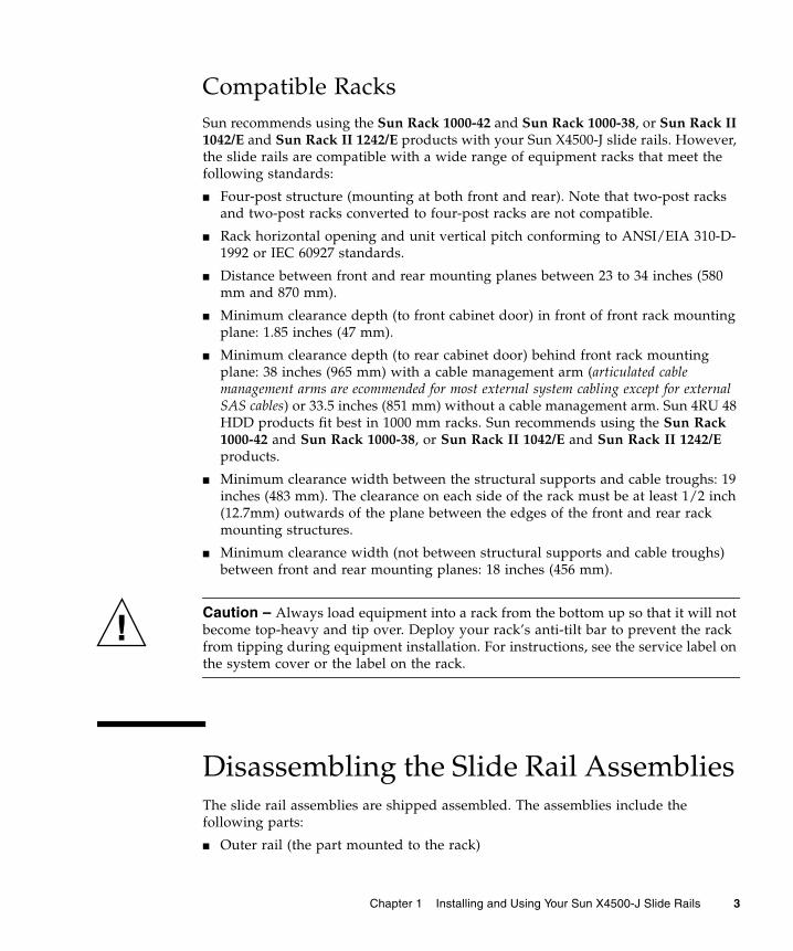
Disassembling the Slide Rail AssembliesThe slide rail assemblies are shipped assembled. The assemblies include thefollowing parts:
■ Outer rail (the part mounted to the rack)
Chapter 1 Installing and Using Your Sun X4500-J Slide Rails 3

■ Middle rail (the sliding part of the assembly)
■ Inner rail (the part mounted to the chassis)
Before you start this procedure, unpack the slide rail assemblies from the packingbox and place them on a flat surface. You must remove the inner rail (as explained inthis procedure) before trying to mount it to the system chassis.
1. Push the system release latch and slide out the inner rail to its fully extendedposition (until it reaches the internal stops). See the inset arrows labeled 1 and2 in FIGURE 1-1.
2. Push the green inner rail release button (with embossed arrow), and remove theinner rail from the slide rail assembly. See the inset arrows labeled 3 and 4 inFIGURE 1-1.
4 Sun X4500-J Slide Rail Installation Guide • February 2009

FIGURE 1-1 Disassembling the Slide Rail Assembly Before Installation
3. Repeat steps 1 and 2 for the remaining slide rail assembly.
Determining Where to Attach the OuterRail/Middle Rail1. Determine where in the rack you want to install the system.
The Sun X4500-J slide rails are designed for Sun 4RU 48 HDD storage products. Apaper rack-mount template is shipped with the slide-rail assembly.
System release latch
Inner rail release button
Chapter 1 Installing and Using Your Sun X4500-J Slide Rails 5

2. Set the rack-mount template above the bottom system mounted in your rack.
3. Prepare to install the outer rail/middle rail at the location indicated by thearrows on the rack-mount template.
In a rack with three holes per rack unit, these systems occupy 12 holes in height.See FIGURE 1-2.
FIGURE 1-2 Determining Where to Attach the Outer Rail/Inner Rail
Attaching the Outer Rail/Middle RailHave the following available before you begin the assembly:
■ #2 Phillips screwdriver
■ 1 set of rail mounting hardware (includes 8 screws)
1. Make sure the slide-rail assembly is adjusted lengthwise to facilitate mountingto the front and rear posts of your rack. See FIGURE 1-3.
Make sure you havesix holes of free spaceabove the outer railbracket
Outer rail bracket
6 Sun X4500-J Slide Rail Installation Guide • February 2009

2. Insert and hand-tighten the bottom screws first to hold each slide rail in place.
The screws should be hand-tightened now because you will use a slide railspacing tool (called the Rack Installation Aid) later to make final adjustments.
■ If your rack has threaded mounting holes in the rack posts, insert the correctmounting screws (standard or metric) through the slide rail brackets and intothe threaded holes.
■ If your rack does not have threaded mounting holes, insert the appropriatemounting screws through both the slide rail brackets and rack posts, and thensecure them with caged nuts.
3. Insert and hand-tighten the rest of the screws in the rail assembly front andrear mounting-bracket holes.
Chapter 1 Installing and Using Your Sun X4500-J Slide Rails 7

FIGURE 1-3 Attaching the Outer Rail/Inner Rail
Rack Installation AidThe Rack Installation Aid (RIA) is used to help with the critical alignment andspacing of the rails to ensure an even fit and prevent tilted alignment.
1. Once both slide rail assemblies are loosely fastened at the front and rear, placethe RIA spacing tool over both slide-rail assemblies at the front of the rack. SeeFIGURE 1-4.
The RIA spacing tool should have a snug fit and might require pressure to ensurethat it is fully engaged with the left and right slide-rail assemblies.
2. Center the bracket holes with the appropriate holes in the rack, and tighten allfour screws on left and right front mounting brackets with a #2 Phillipsscrewdriver. See FIGURE 1-4.
8 Sun X4500-J Slide Rail Installation Guide • February 2009
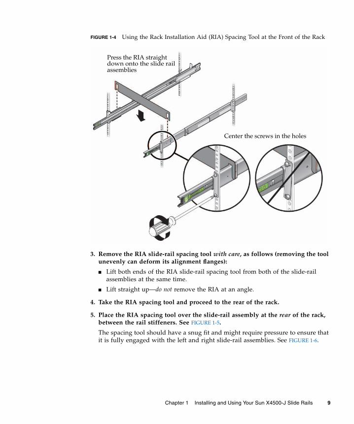
FIGURE 1-4 Using the Rack Installation Aid (RIA) Spacing Tool at the Front of the Rack
3. Remove the RIA slide-rail spacing tool with care, as follows (removing the toolunevenly can deform its alignment flanges):
■ Lift both ends of the RIA slide-rail spacing tool from both of the slide-railassemblies at the same time.
■ Lift straight up—do not remove the RIA at an angle.
4. Take the RIA spacing tool and proceed to the rear of the rack.
5. Place the RIA spacing tool over the slide-rail assembly at the rear of the rack,between the rail stiffeners. See FIGURE 1-5.
The spacing tool should have a snug fit and might require pressure to ensure thatit is fully engaged with the left and right slide-rail assemblies. See FIGURE 1-6.
Press the RIA straightdown onto the slide railassemblies
Center the screws in the holes
Chapter 1 Installing and Using Your Sun X4500-J Slide Rails 9

FIGURE 1-5 Using the Rack Installation Aid (RIA) Spacing Tool at the Rear of the Rack
6. Center the bracket holes with the appropriate holes in the rack, and tighten allfour screws on the left and right rear mounting brackets with a #2 Phillipsscrewdriver. See FIGURE 1-5 and FIGURE 1-6.
Press straight down to installthe RIA onto the slide-rail assembly,between the rail stiffeners
Center the screws in the holes
10 Sun X4500-J Slide Rail Installation Guide • February 2009

FIGURE 1-6 Tighten Screws on the Right Rear Mounting Bracket
7. Carefully, remove the RIA slide rail spacing tool from the rails by lifting bothends of the tool straight up at the same time.
Attaching the Inner Rails to the ChassisThe inner rails must be installed on to the system chassis before installing the systeminto the rack.
1. Pick up one of the inner rails and orient it so that the system release latch istoward the front of the system.
2. Position the inner rail on the chassis by aligning the six-keyed openings on theinner rail with the six mounting pins on the side of the chassis. See FIGURE 1-7.
Chapter 1 Installing and Using Your Sun X4500-J Slide Rails 11

FIGURE 1-7 Attaching the Inner Rail to the Chassis
3. While pressing the front and rear part of the rail against the chassis, slide therail toward the rear of the chassis until the pin retaining clip locks into placewith an audible click. See the inset with the arrow in FIGURE 1-7.
4. Verify that all six mounting pins are properly engaged with the keyed slide-railpin slots.
If the rail does not fit flush against the chassis, reinstall it as described in “How toRemove the Inner Rail From the Chassis if Installed Incorrectly” on page 12.
5. Repeat steps 1 through 4 to install the remaining inner rail on the other side ofthe system.
How to Remove the Inner Rail From the Chassis ifInstalled IncorrectlyIf some of the keyholes on the inner rail did not capture the chassis pins when youinstalled the inner rail to the chassis, do the following:
1. Lift the pin retaining latch as shown in FIGURE 1-8.
Inner rail
System release latch
12 Sun X4500-J Slide Rail Installation Guide • February 2009

2. Push the inner rail forward (toward the front of the system) to remove it.
3. Then repeat steps 1 through 4 in the previous section to reinstall the rail.
FIGURE 1-8 Removing the Inner Rail from the Chassis
Incorrect. Some chassispins are not captured inthe rail keyholes
Chapter 1 Installing and Using Your Sun X4500-J Slide Rails 13
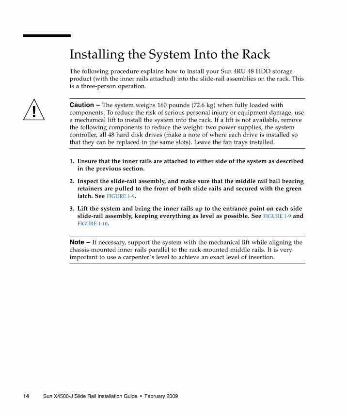
Installing the System Into the RackThe following procedure explains how to install your Sun 4RU 48 HDD storageproduct (with the inner rails attached) into the slide-rail assemblies on the rack. Thisis a three-person operation.
Caution – The system weighs 160 pounds (72.6 kg) when fully loaded withcomponents. To reduce the risk of serious personal injury or equipment damage, usea mechanical lift to install the system into the rack. If a lift is not available, removethe following components to reduce the weight: two power supplies, the systemcontroller, all 48 hard disk drives (make a note of where each drive is installed sothat they can be replaced in the same slots). Leave the fan trays installed.
1. Ensure that the inner rails are attached to either side of the system as describedin the previous section.
2. Inspect the slide-rail assembly, and make sure that the middle rail ball bearingretainers are pulled to the front of both slide rails and secured with the greenlatch. See FIGURE 1-9.
3. Lift the system and bring the inner rails up to the entrance point on each sideslide-rail assembly, keeping everything as level as possible. See FIGURE 1-9 andFIGURE 1-10.
Note – If necessary, support the system with the mechanical lift while aligning thechassis-mounted inner rails parallel to the rack-mounted middle rails. It is veryimportant to use a carpenter’s level to achieve an exact level of insertion.
14 Sun X4500-J Slide Rail Installation Guide • February 2009

FIGURE 1-9 Correct Setup for Inserting the System Into the Slide Rails
Chapter 1 Installing and Using Your Sun X4500-J Slide Rails 15

4. Press in on the green inner-rail release buttons on each of the slide rails (seethe inset arrow labeled 3 in FIGURE 1-1). Slowly move the system in to engagethe inner rails with the slide-rail assembly (see FIGURE 1-10).
Note – Make sure the inner rails enter the middle rails at the correct angle, asshown in FIGURE 1-10.
As you slide the system into the rack, a spotter or observer at the rear of the rackshould make sure the inner rails are engaged with the ball-bearing retainers(shown in FIGURE 1-9) on both slide rails.
FIGURE 1-10 Making Sure Inner Rail Is Inserted at the Correct Angle
5. Slowly push the system all the way into the rack until the slide rail locksengage. There might be moderate resistance during the first insertion as themiddle rails auto-adjust.
Right
WrongWrongWrong
Right
Wrong
16 Sun X4500-J Slide Rail Installation Guide • February 2009

Verifying Slide Rail Operation
Caution – To prevent damage to the system or physical injury, if you are using alift, keep the lift under the system. If you are manually installing the system, holdthe handles on each side of the system.
1. Slide out the system out to its service position by first releasing the latches oneach side of the system, and then sliding it out until it reaches the stops. Seethe inset with arrows labeled 1 and 2 in FIGURE 1-11.
Note – For some rack solutions, clearances can be tight in the lower racks because ofthe rack anti-tilt bar. The system release latch for the slide rails are flanged on eitherside of the embossed triangle to allow fingertip access.
2. If you depopulated the system of hard disk drives during slide rail installation,replace them in the same locations from which they were removed.
3. Push in the green inner rail release button (with embossed arrow—see insetarrow labeled 3 in FIGURE 1-1) on each of the middle rails, and push the systemall the way back into the rack until the slide rail locks engage.
4. If you removed power supplies or the system controller during slide railinstallation, replace those in the same locations from which they were removed.
5. To complete the installation of your Sun rackable 4RU storage product, proceedto the installation instructions supplied with the product for the next steps. Ifyou need to install a cable management assembly, proceed to the next section.
Installing a Cable ManagementAssembly (CMA)If a Cable Management Assembly (CMA) is supported for use with your Sun 4URstorage product, follow the instructions packaged with the CMA to properly installit. There are only certain Sun CMA products that may be used with the Sun X4500-JSlide Rails. Refer to your product documentation for a list.
Chapter 1 Installing and Using Your Sun X4500-J Slide Rails 17

Removing the System from the RackThis procedure assumes you have turned off the system, removed the cablemanagement arm, and removed any cables or cords that would restrict themovement of the system.
Caution – Attempting this procedure without a mechanical lift or with fewer thanfour people could result in personal injury or equipment damage. These systems canweigh up to 160 pounds (72.6 kg) when fully loaded with components. To preventinjury, use a mechanical lift to remove the system from the rack. If only three peopleare available, remove power supplies, hard disks, and system controller to reducethe weight to about 50 pounds before removing the system. Leave the fan traysinstalled.
1. If your system includes a cable management assembly (CMA), remove it anddisconnect all the cables.
2. If you do not have a mechanical lift, remove the following components fromthe rear of the rack to reduce the weight to a safe level for manual lifting:
■ Power supplies
■ System Controller
3. Slide out the system out to its service position by first releasing the latches oneach side of the system, and then sliding it out until it reaches the stops. Seethe inset with arrows labeled 1 and 2 in FIGURE 1-11.
Note – For some rack solutions, clearances can be tight in the lower racks because ofthe rack anti-tilt bar. The system release latch for the slide rails are flanged on eitherside of the embossed triangle to allow fingertip access.
18 Sun X4500-J Slide Rail Installation Guide • February 2009

FIGURE 1-11 Releasing and Sliding out the System from the Rack
4. If you do not have a mechanical lift, open the hard disk drive access cover andremove the hard disk drives.
Caution – Make sure you label the drives so you can replace them in their originallocations.
5. To completely remove the system from the rack, do the following:
a. Press the green release lever (with embossed arrow) on each slide rail todisengage the system inner rails from the slide rail assembly (see the insetarrows labeled 1 and 2 in FIGURE 1-12).
b. Holding the handles located on each side of the system, slide the systemcompletely out of the rack (see label 4 in FIGURE 1-12) and set it down on aclean, stable surface.
Fingertip access
Chapter 1 Installing and Using Your Sun X4500-J Slide Rails 19

FIGURE 1-12 Removing the System from the Rack
6. To prevent the middle rails from blocking access to the aisle as you serviceyour system out of the rack, release the middle rail locks and then slide themiddle rails back inside the outer rails. See FIGURE 1-13.
Note – When reinstalling the system into the rack, first pull the middle rails backout to their locking position (see FIGURE 1-9) before attempting to reinsert the innerrails on the system into the middle and outer slide rails.
20 Sun X4500-J Slide Rail Installation Guide • February 2009

FIGURE 1-13 Releasing the Middle Rail Lock
Chapter 1 Installing and Using Your Sun X4500-J Slide Rails 21

22 Sun X4500-J Slide Rail Installation Guide • February 2009