Sun SPARC Enterprise M-Series Servers - Configuration · PDF fileSUN SPARC® ENTERPRISE...
45
SUN SPARC® ENTERPRISE M-SERIES SERVERS CONFIGURATION CONCEPTS James Hsieh, Sun Systems Group Sun BluePrints™ Online Part No 820-7132-10 Revision 1.0, 12/17/08
Transcript of Sun SPARC Enterprise M-Series Servers - Configuration · PDF fileSUN SPARC® ENTERPRISE...

SUN SPARC® ENTERPRISE M-SERIES SERVERSCONFIGURATION CONCEPTS James Hsieh, Sun Systems Group
Sun BluePrints™ Online
Part No 820-7132-10Revision 1.0, 12/17/08

Sun Microsystems, Inc.
Table of Contents
Introduction. . . . . . . . . . . . . . . . . . . . . . . . . . . . . . . . . . . . . . . . . . . . . . . . . . . . . . . .1
Basic Configuration Concepts . . . . . . . . . . . . . . . . . . . . . . . . . . . . . . . . . . . . . . . . . .2
Types of Systems. . . . . . . . . . . . . . . . . . . . . . . . . . . . . . . . . . . . . . . . . . . . . . . . . . . . . 2
Overview of Configurable Components. . . . . . . . . . . . . . . . . . . . . . . . . . . . . . . . . . . . 4
CPUs and System Boards . . . . . . . . . . . . . . . . . . . . . . . . . . . . . . . . . . . . . . . . . . . . 4
Memory and Memory Modules . . . . . . . . . . . . . . . . . . . . . . . . . . . . . . . . . . . . . . . 7
I/O Units. . . . . . . . . . . . . . . . . . . . . . . . . . . . . . . . . . . . . . . . . . . . . . . . . . . . . . . . . 8
Important Concepts . . . . . . . . . . . . . . . . . . . . . . . . . . . . . . . . . . . . . . . . . . . . . . . . . . 9
Physical System Boards (PSBs) . . . . . . . . . . . . . . . . . . . . . . . . . . . . . . . . . . . . . . . 10
The eXtended System Board (XSB) . . . . . . . . . . . . . . . . . . . . . . . . . . . . . . . . . . . . 10
Understanding Connectivity Between Components . . . . . . . . . . . . . . . . . . . . . . . 13
Basic Configuration Examples. . . . . . . . . . . . . . . . . . . . . . . . . . . . . . . . . . . . . . . . . . 15
Adding Components to the Sun SPARC Enterprise M4000 and M5000 Servers . . . 15
Adding Components to the Sun SPARC Enterprise M8000 and M9000 Servers . . . 22
Advanced Configuration Concepts. . . . . . . . . . . . . . . . . . . . . . . . . . . . . . . . . . . . . . 24
Quad-XSB Configurations . . . . . . . . . . . . . . . . . . . . . . . . . . . . . . . . . . . . . . . . . . . . . 24
Quad-XSB Mode and IOUs. . . . . . . . . . . . . . . . . . . . . . . . . . . . . . . . . . . . . . . . . . . 26
Dynamic System Domain Configuration Examples . . . . . . . . . . . . . . . . . . . . . . . . . . 27
Domain Configurations and RAS Concerns . . . . . . . . . . . . . . . . . . . . . . . . . . . . . . 31
Advanced Memory Configuration . . . . . . . . . . . . . . . . . . . . . . . . . . . . . . . . . . . . . . . 32
Memory Configuration Rules . . . . . . . . . . . . . . . . . . . . . . . . . . . . . . . . . . . . . . . . 32
Adding DIMMs with Different Capacities . . . . . . . . . . . . . . . . . . . . . . . . . . . . . . . 32
Memory Mirroring Configurations . . . . . . . . . . . . . . . . . . . . . . . . . . . . . . . . . . . . 35
I/O Performance Considerations. . . . . . . . . . . . . . . . . . . . . . . . . . . . . . . . . . . . . . . . 36
PCIe Slot Utilization . . . . . . . . . . . . . . . . . . . . . . . . . . . . . . . . . . . . . . . . . . . . . . . 36
PCIe Relaxed Ordering . . . . . . . . . . . . . . . . . . . . . . . . . . . . . . . . . . . . . . . . . . . . . 37
Software Notes . . . . . . . . . . . . . . . . . . . . . . . . . . . . . . . . . . . . . . . . . . . . . . . . . . . . 38
XSCF Units. . . . . . . . . . . . . . . . . . . . . . . . . . . . . . . . . . . . . . . . . . . . . . . . . . . . . . . . . 38
XSCFU Functionality . . . . . . . . . . . . . . . . . . . . . . . . . . . . . . . . . . . . . . . . . . . . . . . 38
Email Alerts. . . . . . . . . . . . . . . . . . . . . . . . . . . . . . . . . . . . . . . . . . . . . . . . . . . . . . 39
XCP Software Versions . . . . . . . . . . . . . . . . . . . . . . . . . . . . . . . . . . . . . . . . . . . . . 39
Solaris™ OS Compatibility . . . . . . . . . . . . . . . . . . . . . . . . . . . . . . . . . . . . . . . . . . . . . 40
Required Solaris Packages . . . . . . . . . . . . . . . . . . . . . . . . . . . . . . . . . . . . . . . . . . 40
Summary . . . . . . . . . . . . . . . . . . . . . . . . . . . . . . . . . . . . . . . . . . . . . . . . . . . . . . . . . 41
About the Author . . . . . . . . . . . . . . . . . . . . . . . . . . . . . . . . . . . . . . . . . . . . . . . . . . . 41
Acknowledgements. . . . . . . . . . . . . . . . . . . . . . . . . . . . . . . . . . . . . . . . . . . . . . . . . . 41
References . . . . . . . . . . . . . . . . . . . . . . . . . . . . . . . . . . . . . . . . . . . . . . . . . . . . . . . . 41
Related Resources. . . . . . . . . . . . . . . . . . . . . . . . . . . . . . . . . . . . . . . . . . . . . . . . . . . 42

1 Introduction Sun Microsystems, Inc.
Chapter 1
Introduction
The Sun SPARC® Enterprise M-series server line is the newest addition to Sun
Microsystem’s mid-range and high-end server families. Designed for the enterprise-
class datacenter, all members of the server line offer a great deal of configuration
flexibility in addition to high performance and reliability. The configuration flexibility
offered by these platforms provides multiple deployment options that require careful
consideration. This Sun Blueprints™ article covers basic and advanced configuration
concepts and goes through several sample configurations for the Sun SPARC®
Enterprise M4000, M5000, M8000, and M9000 servers. This article should help readers
avoid common configuration mistakes. Please note, the entry-level Sun SPARC
Enterprise M3000 server is not covered in this article.
This document is not intended to serve as a complete reference for configuring and
operating the Sun SPARC Enterprise M-series servers and should not be considered as a
replacement for the official product documentation located at docs.sun.com. This
Sun Blueprints™ article should be used as a supplement to explain the key concepts and
help navigate through the official product documentation.
The intended audiences for this document are end-users and system resellers that need
to understand how to best configure the highly flexible Sun SPARC Enterprise server
line. The reader should be familiar with basic computing principles and computer
hardware at the component level such as CPUs, memory, and I/O busses.

2 Basic Configuration Concepts Sun Microsystems, Inc.
Chapter 2
Basic Configuration Concepts
This chapter presents the fundamental concepts for properly configuring the Sun SPARC
Enterprise M-series servers. The base configurations of the systems are defined along
with several examples describing the installation of additional components such as
CPU and memory. An overview of the major configurable components is presented as
well.
Types of SystemsWhile all of the systems in the Sun SPARC Enterprise M-series server line share a
common architecture, they can be grouped into two sets, the rackmount systems and
the systems that occupy one or more full-sized cabinets. The Sun SPARC Enterprise
M4000 server is 6 rack units (RU) high. It can have a maximum of four CPUs. The Sun
SPARC Enterprise M5000 server is 10 RU high, and can have a maximum of eight CPUs.
These servers are very similar and share many common components. Table 1 provides a
summary of the rackmount systems.
Table 1. Rackmount systems summary.
DescriptionSun SPARC
Enterprise M4000 Server
Sun SPARC Enterprise M5000
Server
Size 6 RU 10 RU
Total CPU sockets 4 8
Maximum CPU cores (dual-core/quad-core) 8/16 16/32
Maximum CPUM (CPU modules, 2 CPUs each) 2 4
Total Dual In-line Memory Modules (DIMMs) sockets 32 64
Maximum memory (1/2/4 GB DIMMs) 32/64/128 GB 64/128/256 GB
Maximum MEMBs (memory boards, 8 DIMM sockets each) 4 8
Total DIMM sockets 32 64
Maximum I/O Units (IOUs) 1 2
Maximum PCI Express (PCIe) slots 4 per IOU (without external expansion) 4 8
Maximum PCI Extended (PCI-X) slots 1 per IOU (without external expansion) 1 2
Maximum internal 2.5-inch serial attached SCSI (SAS) disks (2 per IOU)
2 4
Physical System Boards (PSBs) equivalents 1 2

3 Basic Configuration Concepts Sun Microsystems, Inc.
The Sun SPARC Enterprise M8000 and M9000 servers are housed in one or more full
rack-sized cabinets. These systems share many common components with each other,
but not with the rackmount systems. Table 2 lists the details for the full cabinet-sized
systems.
Table 2.
Number of cabinets 1 1 2
Maximum CPU sockets 16 32 64
Maximum CPU cores (dual/quad) 32/64 64/128 128/256
Maximum DIMMs 128 256 512
Maximum memory (4 GB DIMMs) 512 GB 1 TB 2 TB
Maximum CMUs 4 8 16
Maximum IOUs 4 8 16
Maximum PCIe slots 32 64 128
Maximum 2.5-inch SAS internal disks (2 x 2 per IOU)
16 32 64
Maximum physical system boards 4 8 16
Maximum Dynamic System Domains 16 24 24
eXtended Service Control Facility U-units 2 2 2
Full cabinet-sized systems.
Given the differences between the system types, the discussions in this article are
grouped into separate sections for the rackmount or cabinet-sized systems. More
details on the Sun SPARC Enterprise servers can be found on the Sun Web site at:
sun.com/sparcenterprise.
Maximum Dynamic System Domains 2 4
eXtended Service Control Facility Units (XSCFU) 1 1
Power Supply Units (PSUs) 2 4
Description
Sun SPARC Enterprise
M8000Server
Sun SPARC Enterprise M9000-32
Server
Sun SPARC Enterprise M9000-64
Server
DescriptionSun SPARC
Enterprise M4000 Server
Sun SPARC Enterprise M5000
Server

4 Basic Configuration Concepts Sun Microsystems, Inc.
Overview of Configurable ComponentsThe primary components that are typically considered when configuring a system are
CPUs, memory, and I/O. While the underlying technology and many of the
configuration rules are the same across all of the servers in this line, there are
differences in the physical packaging of the components between the rackmount Sun
SPARC Enterprise M4000 and M5000 servers and the larger full cabinet-sized Sun SPARC
Enterprise M8000 and M9000 servers.
CPUs and System Boards
The Sun SPARC Enterprise M-series servers utilize SPARC64® processors. Two processors
are available, the SPARC64 VI dual-core CPU, which provides two processing cores in a
single physical CPU chip, and the SPARC64 VII, which provides four cores. Throughout
this blueprint article the term CPU refers to the physical chip, regardless of how many
processing cores it contains.
CPUs for the Sun SPARC Enterprise M4000 and M5000 servers are built into a module
called a CPUM, that contains two physical CPUs as illustrated in Figure 1. The CPUMs
plug into slots on the motherboard.
Figure 1. CPUM for the Sun SPARC Enterprise M4000 or M5000 server.
The Sun SPARC Enterprise M4000 server’s motherboard accepts up to two CPUMs,
which allows either two or four CPUs. See Figure 2 for a picture of the Sun SPARC
Enterprise M4000 server’s motherboard. Figure 3 shows a block diagram of a fully
populated system.

5 Basic Configuration Concepts Sun Microsystems, Inc.
Figure 2. Sun SPARC Enterprise M4000 server motherboard.
M5000 MBU
Uni-XSB 00-0(PSB 0 and IOU 0)
DVD
Opt. DAT
CPU 2
CPU 3
CPUM 1
MEMB 2(8 DIMMS)
MEMB 3(8 DIMMS)
SAS Disk 0
SAS Disk 1
PCI-X Slot 0PCle Slot 1PCle Slot 2
CPU 0
CPU 1
CPUM 0
MEMB 0(8 DIMMS)
MEMB 1(8 DIMMS)
PCle Slot 3
PCle Slot 4
M5000 IOU 0
Figure 3. Block diagram of a fully populated Sun SPARC Enterprise M4000 server.
The Sun SPARC Enterprise M5000 server includes sockets for up to four CPUMs, for a
maximum configuration of eight CPUs, providing up to 16 processor cores when
utilizing dual-core SPARC64 VI CPUs or 32 cores when using SPARC64 VII CPUs. While the
system has a single motherboard, it is the logical equivalent of two Sun SPARC

6 Basic Configuration Concepts Sun Microsystems, Inc.
Enterprise M4000 system boards with up to two CPUMs each. The distinction is
important for understanding configuration rules that are covered in the next section.
See Figure 4 for a block diagram of a fully populated Sun SPARC Enterprise M5000
server.
M5000 MBU M5000 IOU 1
Uni-XSB 00-0(PSB 0 and IOU 0)
DVD
Opt. DAT
CPU 2
CPU 3
CPUM 1
MEMB 2(8 DIMMS)
MEMB 3(8 DIMMS)
SAS Disk 0
SAS Disk 1
PCI-X Slot 0PCle Slot 1PCle Slot 2
CPU 0
CPU 1
CPUM 0
MEMB 0(8 DIMMS)
MEMB 1(8 DIMMS)
PCle Slot 3
PCle Slot 4
M5000 IOU 0
Uni-XSB 01-0(PSB 1 and IOU 1)
SAS Disk 3PCle Slot 1PCle Slot 2
PCI-X Slot 0MEMB 4
(8 DIMMS)
PCle Slot 3
PCle Slot 4
CPU 4
CPU 5
CPUM 3
MEMB 5(8 DIMMS)
CPU 6
CPU 7
CPUM 4
MEMB 6(8 DIMMS)
MEMB 7(8 DIMMS)
SAS Disk 2
Figure 4. Block diagram of a fully populated Sun SPARC Enterprise M5000 server.
CPUs for the full cabinet-sized systems are installed on a board that contains both CPUs
and memory, which is referred to as a CPU and Memory Unit (CMU). Either two or four
CPUs can be installed on a CMU board. The Sun SPARC Enterprise M8000 server allows
up to 4 CMU boards to be installed for a maximum configuration of 16 physical CPUs.
The single-cabinet Sun SPARC Enterprise M9000-32 server can hold up to 8 CMU boards,
while the dual-cabinet Sun SPARC Enterprise M9000-64 server doubles that number to
16 CMUs for a maximum of 64 CPUs. The CMU boards are hot-swappable, which is
important for reliability, availability, and serviceability (RAS). Figure 5 shows a picture
of a CMU board.

7 Basic Configuration Concepts Sun Microsystems, Inc.
Figure 5. CMU for Sun SPARC Enterprise M8000 or M9000 servers.
Memory and Memory Modules
Similar to the way the Sun SPARC Enterprise M4000 and M5000 servers use easily
installed modules for CPUs, an assembly referred to as an MEMB (memory board),
shown below in Figure 6, is used to house the memory. The Sun SPARC Enterprise
M4000 system board, shown above in Figure 2, has slots for up to four MEMBs. The Sun
SPARC Enterprise M5000 server has slots for up to eight MEMBs. Each MEMB slot has a
relationship to a particular CPU. There are a number of rules for MEMB placement that
are explained later in this article.
Figure 6. Picture of a Sun SPARC Enterprise M4000 or M5000 server MEMB.

8 Basic Configuration Concepts Sun Microsystems, Inc.
Each MEMB has sockets for up to eight Dual In-line Memory Modules (DIMMs) that are
arranged in two groups of four. All four sockets in a group must be populated using
identical DIMMs. Therefore, there are only two valid DIMM configurations, half
populated with four DIMMs in the first group (Group A) and fully populated with all
eight DIMMs completing both groups (Groups A and B).
The DIMMs for the Sun SPARC Enterprise M8000 and M9000 servers are installed
directly on the CPU and memory boards (CMUs). Each CMU has 32 DIMM sockets
arranged in two groups of 16 DIMMs each. Each group must be completely populated
with identical DIMMs. Therefore, there are only two valid configurations, 16 DIMMs in
the first group (Group A) or 32 DIMMs completing both groups (Group A and B). One GB,
2 GB, or 4 GB DIMMs can be utilized. Generally, the same capacity DIMMs need to be
used. There are a few specific cases where different sized DIMMs can be installed.
Additional information on memory configuration is covered in “Advanced Memory
Configuration” on page 32.
I/O Units
I/O is added to the SPARC Enterprise M-series servers through assemblies called I/O
Units (IOUs) that contain a number of slots for PCI Express (PCIe) cards. The Sun SPARC
Enterprise M4000 server has one IOU that provides four PCIe slots and one PCI Extended
(PCI-X) slot. The IOU also has several on-board devices that don’t take up any slots: two
1 gigabit Ethernet ports, a controller for two Serial Attached SCSI (SAS) 2.5-inch disk
drives, and a serial ATA (SATA) controller for the DVD and optional DAT drive. The drives
are installed in the system chassis, but the IOU is needed to provide connectivity to the
rest of the system. The Sun SPARC Enterprise M5000 server can house up to two IOUs.
The second IOU is required for connectivity to the third and fourth built-in disk drives.
There is a fixed relationship between the IOU and specific CPU/memory modules. The
first IOU is associated with CPUM 0 and 1, and MEMB 0 through MEMB 3. The second
IOU is associated with CPUM 2 and 3, and MEMB 4 through MEMB 7. The configuration
rules are covered in detail later in this article.
The Sun SPARC Enterprise M8000 and M9000 server IOUs (see Figure 7) have eight PCIe
slots and can hold up to four 2.5-inch SAS disks in a 2 x 2 configuration. Unlike the IOUs
in the Sun SPARC Enterprise M4000 and M5000 servers, there are no on-board
controllers. The IOU Adapter card (IOUA) provides two 1 gigabit Ethernet ports and a
SAS controller for up to two drives. IOUA card can be placed in any of the even
numbered PCIe slots. However, an IOUA is required in slot 0 in order to utilize disks 0
and 1, and slot 4 for disks 2 and 3. The system chassis contains a DVD drive and optional
DAT drive. An IOU with an IOUA is required to access these peripherals.

9 Basic Configuration Concepts Sun Microsystems, Inc.
Figure 7. IOU for a Sun SPARC Enterprise M8000 or M9000 server.
The number of slots available for IOUs in the Sun SPARC Enterprise M8000, M9000-32,
and M9000-64 servers are the same as the number of slots for CMUs: 4, 8, or 16. There
is a fixed relationship between the CMU slot and the IOU slot. An IOU cannot be
utilized by the system unless there is CPU and memory installed on the CMU in the
corresponding slot. However, the IOU is not required for CPU and memory to operate.
An external I/O expansion box is available for use with all of the Sun SPARC Enterprise
M-series servers that can provide additional PCIe or PCI-X slots. The external I/O
expansion box requires that a PCIe link card be installed in the appropriate IOU for
connectivity. Details on the external I/O expansion box are beyond the scope of this
Sun BluePrint. More information can be found at:
sun.com/servers/midrange/external_io.
Important ConceptsConfiguring servers is most often done by thinking in terms of individual numbers of
CPUs, amounts of memory, and I/O slots. The flexibility, performance, and reliability
aspects of the Sun SPARC Enterprise M-series servers require a more holistic view in
thinking about CPU, memory, and I/O together as a system. In these servers, resources
are grouped into physical system boards. There are fixed relationships between CPUs
and DIMMs on the physical system board. Additionally, there are fixed relationships

10 Basic Configuration Concepts Sun Microsystems, Inc.
between IOUs and system boards. The eXtended System Board (XSB) comprised of CPU,
memory, and optionally I/O, is the fundamental configuration unit for the Sun SPARC
Enterprise M-series systems. Many configuration mistakes can be avoided by thinking
in terms of XSBs.
Physical System Boards (PSBs)
The Sun SPARC Enterprise M-series servers use a concept of a Physical System Board
(PSB) that consists of up to four CPUs and 32 DIMMs. The Sun SPARC Enterprise M8000
and M9000 server CMU board is perhaps the clearest example of a PSB. The Sun SPARC
Enterprise M4000 server’s motherboard represents one physical system board. The Sun
SPARC Enterprise M5000 server has the equivalent of two PSBs even though it only has
one motherboard. While the packaging of the PSB is different across these systems, the
capacity for components, and therefore, the configuration rules, are very similar.
The PSB also contains two or four System Controller (SC) Application Specific Integrated
Circuits (ASICs) that are the communication hubs of the system. The SCs connect CPUs,
memory controllers, and I/O systems. On the Sun SPARC Enterprise M8000 and M9000
servers, the four System Controllers also provide connectivity to other system boards by
connecting to the cross-bar switch that provides a high bandwidth and low latency data
backbone. Figure 8 shows a block diagram of a Sun SPARC Enterprise M4000 server PSB.
CPUModule
CPUModule
SC1SC0
8DIMM
sMAC1
8DIMM
sMAC0 CPU0 CPU1
MemoryBoard
MemoryBoard
CPU2 CPU3 MAC2
MemoryBoard
MAC38
DIMMs
8DIMMs
MemoryBoard
Figure 8. Block diagram of a Sun SPARC Enterprise M4000 system PSB.
The eXtended System Board (XSB)
The eXtended System Board (XSB) is the combination of a CPU, memory, and I/O when
available. For example, on a Sun SPARC Enterprise M8000 server, the combination of
CMU 0 and IOU 0 make up an XSB. The XSB is the primary unit used in configuration
and other system operations. Multiple XSBs can be combined to build domains that
have more than four CPUs. The XSB is a very important concept for understanding how
to configure the Sun SPARC Enterprise M-series servers. It is best to think of XSBs and
not individual components. A fundamental rule is that every XSB must have both CPU
and memory. An XSB that only has CPU or only has memory cannot be used by the
system. An IOU cannot be used unless both its associated CPU and memory are

11 Basic Configuration Concepts Sun Microsystems, Inc.
present, thus forming a complete XSB. See Figure 9 for an example of a complete XSB
for a Sun SPARC Enterprise M8000 or M9000 server. An example showing a Sun SPARC
Enterprise M5000 server with two complete XSBs can be found in Figure 4 on page 6.
The XSB can be set to one of two logical configurations, Uni-XSB or Quad-XSB mode.
Uni-XSB mode uses all of the resources of the entire PSB and IOU as a single unit. Uni-XSB mode is illustrated in Figure 9.
CMU
CPU 1
CPU 3
CPU 2
CPU 0
8 DIMMS
8 DIMMS
8 DIMMS
8 DIMMS
PCIe Slot 7
PCIe Slot 6
PCIe Slot 3
PCIe Slot 2
IOU
PCIe Slot 1
PCIe Slot 0IOUA Card
PCIe Slot 5
PCIe Slot 4IOUA Card
SAS Disk 0SAS Disk 1
SAS Disk 2Uni-XSB 00
SAS Disk 3
Figure 9. A Sun SPARC Enterprise M8000 or M9000 server CMU and IOU in Uni-XSB
mode.
Quad-XSB mode divides the available resources into quarters to make four XSBs with
one CPU and four or eight DIMMs each. This allows finer-grained configuration choices.
If an IOU is present, it is part of the same XSB and operates in the same mode, Uni- or
Quad-XSB. For example, a Sun SPARC Enterprise M8000 or M9000 server IOU provides
each quad in Quad-XSB mode with two PCIe slots, as shown in Figure 10.

12 Basic Configuration Concepts Sun Microsystems, Inc.
Quad-XSB 00-2
Quad-XSB 00-3
Quad-XSB 00-1
CMU
Quad-XSB 00-0
CPU 1
CPU 3
CPU 2
CPU 0
8 DIMMS
8 DIMMS
8 DIMMS
8 DIMMS
PCIe Slot 7
PCIe Slot 6
PCIe Slot 3
PCIe Slot 2
IOU
PCIe Slot 1
PCIe Slot 0IOUA Card
PCIe Slot 5
PCIe Slot 4IOUA Card
SAS Disk 0SAS Disk 1
SAS Disk 2SAS Disk 3
Figure 10. A Sun SPARC Enterprise M8000 or M9000 server CMU and IOU in Quad-XSB mode.
The IOUs used in the Sun SPARC Enterprise M4000 and M5000 servers do not have
enough resources to distribute among all four parts of the Quad-XSB. Instead the I/O
resources are allocated to the first two quads as shown in Figure 11. The third and forth
Quad-XSBs do not have any I/O. Note that I/O is not a requirement for an XSB, only
CPU and memory are required. However, in order to boot and be functional, those XSBs
would have to be combined with at least one other XSB that does have I/O. The section
on “Dynamic System Domain Configuration Examples” on page 27 provides additional
details on utilizing XSBs in domains.
DVD
Opt. DAT
SAS Disk 0
SAS Disk 1
PCI-X Slot 0PCle Slot 1PCle Slot 2
Quad-XSB 00-0MEMB 0
(8 DIMMS)
Quad-XSB 00-1 PCle Slot 4PCle Slot 3
MEMB 1(8 DIMMS)
Quad-XSB 00-2
M4000 IOUM4000 MBU
Quad-XSB 00-3MEMB 3(8 DIMMS)
MEMB 2(8 DIMMS)CPU 2
CPU 3
CPUM 1
CPU 0
CPU 1
CPUM 0
Figure 11. Sun SPARC Enterprise M4000 server in Quad-XSB mode.

13 Basic Configuration Concepts Sun Microsystems, Inc.
The flexibility of using Quad-XSBs for fine-grained allocation of resources comes with
the price of additional configuration rules that increase installation complexity. For example, there are configurations that are valid in Uni-XSB mode, but are not valid
for Quad-XSB mode because they lack CPU or memory. This chapter only provides
guidance on Uni-XSB configurations. Quad-XSBs are discussed in more detail in the
section “Quad-XSB Configurations” on page 24.
Understanding Connectivity Between Components
Many of the configuration rules for the Sun SPARC Enterprise M-series systems are
determined by the way components are dependent on each other. Invalid
configurations occur when components are isolated with no directly usable path.
Therefore, it is particularly important to understand the connections within an XSB.
CPU and Memory
CPUs and memory are connected by the SC on their PSBs as illustrated in Figure 8 on
page 10. A CPU can only operate with memory that is on the same XSB. A CPU on an
XSB with no memory cannot be used. Similarly, memory on an XSB without a CPU
cannot be used. In Uni-XSB mode, a CPU can utilize all of the memory on the same
board.
In Quad-XSB mode the resources are partitioned into quarters. The SC is responsible for
the partitioning. This mode creates an even tighter relationship between CPUs and
memory. For example, on a Sun SPARC Enterprise M4000 server, the first CPU on CPUM 0 only has access to the memory on MEMB 0. Similarly, the second CPU on
CPUM 0 only has access to MEMB 1. If MEMB 1 isn’t present the second CPU doesn’t
have memory, and is therefore not a valid configuration for Quad-XSB mode (Figure 12).
This topic is discussed in further detail in “Adding Components to the Sun SPARC
Enterprise M4000 and M5000 Servers” on page 15 and “Quad-XSB Configurations” on
page 24.

14 Basic Configuration Concepts Sun Microsystems, Inc.
Quad-XSB 00-2
M4000 IOUM4000 MBU
Quad-XSB 00-3MEMB Slot 3Empty
MEMB Slot 2Empty
CPUMSlot 1Empty
Quad-XSB 00-1PCle Slot 4PCle Slot 3MEMB Slot 1
Empty
DVD
Opt. DAT
SAS DISK 0
SAS DISK 1
PCI-X Slot 0PCle Slot 1PCle Slot 2
Quad-XSB 00-0MEMB 0
(8 DIMMS)CPU 0
CPU 1
CPUM 0
Figure 12. Invalid Quad-XSB configuration for a Sun SPARC Enterprise M4000
server: CPU 1 cannot be used.
I/O Units and Physical System Boards
Each IOU is tied to a specific PSB by its position in the system. The System Controllers
provide the connections between the CPU, memory, and the IOU. An IOU can only be
utilized by the system if there is CPU and memory in the associated slots. On the Sun
SPARC Enterprise M8000 and M9000 servers, there is a direct relationship between
CMU slot numbers and IOU slot numbers. For example, IOU 3 is connected to CMU 3.
The Sun SPARC Enterprise M5000 server can have two IOUs. This system has the
equivalent of two PSBs, even though they are packaged into a single motherboard. PSB 0 is connected to the first IOU. The second IOU is connected to PSB 1. As a result,
there must be CPUs and memory on PSB 1 in order to utilize the I/O provided by the
second IOU. At a minimum, CPUM slot 2 and MEMB slot 4 must be populated in order
to utilize IOU1. See Figure 4 on page 6 for a block diagram.
Internal 2.5-inch SAS Disk Drives
The Sun SPARC Enterprise M-series servers have bays for 2.5-inch SAS disk drives that
are typically utilized as boot disks. The drives are used as mirrored pairs for higher
availability. The IOUs on the Sun SPARC Enterprise M4000 and M5000 servers provide
the SAS controller for these drives. The Sun SPARC Enterprise M4000 server has room
for two drives, while the Sun SPARC Enterprise M5000 server has room for an additional
pair of drives. The first two drives are connected to the first IOU. In order to use the
second pair of drives on the Sun SPARC Enterprise M5000 server, the second IOU must
be present to provide the controller. This also means that CPU and memory must be

15 Basic Configuration Concepts Sun Microsystems, Inc.
present on the second PSB as detailed in the section above. If the system board is used
in Quad-XSB mode, the drives are attached to the first XSB (Figure 11). Additional
details can be found in “Quad-XSB Configurations” on page 24.
The IOUs for the Sun SPARC Enterprise M8000 and M9000 servers have four drive bays
that provide for up to two pairs of boot disks. The IOUs for these systems do not have
on-board controllers. An IOUA PCIe card needs to be installed for each pair of drives that
are used, in PCIe slot 0 for disk 0 and 1, and PCIe slot 4 for disk 2 and 3. In Quad-XSB
mode, the first pair of disks are part of the first XSB (XSB 0) and the second pair are part
of the third (XSB 2), as illustrated in Figure 10 on page 12.
On-Board DVD and Optional DAT Drives
The on-board DVD and optional DAT drives are connected in a similar manner to the SAS
disk drives described in the previous section. On the Sun SPARC Enterprise M4000 and
M5000 servers, the DVD and DAT drives have a fixed association with the first XSB on
the first PSB. The second IOU on the Sun SPARC Enterprise M5000 server does not have
the options for DVD or DAT drives. If the drives are needed by another domain, XSB 00-0
must be temporarily assigned to that domain. More information is available in
“Dynamic System Domain Configuration Examples” on page 27.
The DVD and DAT drives on the Sun SPARC Enterprise M8000 and M9000 servers can be
dynamically assigned to the XSB that requires it by using the XSCF as long as the XSB
has an IOUA card available in an even numbered PCIe slot. See Table 4 on page 26
Basic Configuration ExamplesThis section covers some basic configuration examples for each of the systems. The
base configurations as they appear on the current Sun price list are used as a starting
point. CPU, memory, and I/O are then added to demonstrate some of the key
configuration rules and highlight some common configuration mistakes.
In the basic examples, only Uni-XSB configurations are used to keep things
straightforward. In Uni-XSB mode, many of the configuration rules are somewhat
relaxed. However, there are valid Uni-XSB configurations that are not valid for Quad-
XSB mode. If the requirements call for XSBs that can operate in either Uni- or Quad-XSB
mode, then all of the Quad-XSB configuration rules need to be adhered to as well. See
“Advanced Configuration Concepts” on page 24 for more information.
Adding Components to the Sun SPARC Enterprise M4000 and M5000 Servers
This section provides guidelines on adding and configuring components to the
rackmount systems.

16 Basic Configuration Concepts Sun Microsystems, Inc.
Sun SPARC Enterprise M4000 and M5000 Server Base Configurations
The Sun SPARC Enterprise M4000 server base configuration includes one CPUM (which
includes two dual-core CPUs) and 8 GB of memory in two MEMBs. Each MEMB has four
1 GB DIMMs installed in the first group, Group A. The modules are all installed in the
lowest numbered slots, the CPUM in slot 0, the MEMBs in slots 0 and 1 (Figure 13). The base configuration for the Sun SPARC Enterprise M5000 server is the same, but
there is a second PSB that has no CPU or memory installed.
M4000 IOUM4000 MBU
MEMB Slot 3Empty
MEMB Slot 2Empty
CPUM Slot 1Empty
Uni-XSB 00PCle Slot 4
PCle Slot 3MEMB 1(4 x 1 GB)
DVD
Opt. DAT
SAS DISK 0
SAS DISK 1
PCI-X Slot 0PCle Slot 1PCle Slot 2
MEMB 0(4 x 1 GB)CPU 0
CPU 1
CPUM 0
Figure 13. Sun SPARC Enterprise M4000 server base configuration.
Adding CPU Modules to the Sun SPARC Enterprise M4000 and M5000 Servers
Adding CPUs to the base configuration of the Sun SPARC Enterprise M4000 server is
straightforward, since there is only one available slot for another CPUM. Adding a
CPUM increases the number of CPUs from two to the maximum of four as shown in
Figure 14.

17 Basic Configuration Concepts Sun Microsystems, Inc.
DVD
Opt. DAT
SAS DISK 0
SAS DISK 1
PCI-X Slot 0PCle Slot 1PCle Slot 2
MEMB 0(4 x 1 GB)
PCle Slot 4
PCle Slot 3MEMB 1(4 x 1 GB)
CPU 0
CPU 1
CPUM 0
Uni-XSB 00
M4000 IOUM4000 MBU
MEMB Slot 2Empty
MEMB Slot 3Empty
CPU 2
CPU 3
CPUM 1
Figure 14. Sun SPARC Enterprise M4000 server base configuration with an
additional CPUM.
The Sun SPARC Enterprise M5000 server has room to add from one to three CPUMs.
There is a choice for where to place the second CPUM that depends on how the system
is to be used. If the CPUM is plugged into the second slot on the first system board, no
additional memory is required as long as the system is used in Uni-XSB mode. This is a
good choice if more processing power is needed without additional I/O. Note that this
is the essentially same configuration as the system shown in Figure 14 above.
Remember, the Sun SPARC Enterprise M4000 server can be thought of as a Sun SPARC
Enterprise M5000 server with only one PSB and one IOU.
Alternatively, the first additional module could be plugged into the third CPUM slot,
which makes it the first two CPUs for the second PSB. A CPUM is required in slot 2 if an
additional IOU is needed to provide enough I/O resources. However, at least one
MEMB needs to be added to the second PSB in MEMB slot 4 to make it a valid XSB with
CPU and memory. Figure 15 shows an invalid configuration. Without the memory, the
system is not able to utilize either the CPUs or the IOU.

18 Basic Configuration Concepts Sun Microsystems, Inc.
Uni-XSB 00-0(PSB 0 and IOU 0)
Uni-XSB 01-0(PSB 1 and IOU 1)
M5000 MBU
MEMB Slot 6Empty
MEMB Slot 7Empty
MEMB 0
MEMB Slot 3Empty
MEMB Slot 2Empty
MEMB Slot 4EmptyCPU 4
CPU 5
CPUM 2
CPUM Slot 3Empy
CPU 0
CPU 1
CPUM 0
CPUMSlot 1Empty
M5000 IOU 1
DVD
Opt. DAT
SAS Disk 0
SAS Disk 1PCle Slot 1PCle Slot 2
PCI-X Slot 0
MEMB Slot 5Empty
PCle Slot 3
PCle Slot 4
DVD
Opt. DAT
SAS Disk 0
SAS Disk 1
PCI-X Slot 0PCle Slot 1PCle Slot 2
MEMB Slot 1Empty
PCle Slot 3
PCle Slot 4
M5000 IOU 0
Figure 15. Invalid Sun SPARC Enterprise M5000 server configuration, no memory
on PSB 1.
Once memory is added to PSB 1, the result is a system with two valid Uni-XSBs. This is
the configuration that is required to support the second IOU since it is tied to PSB 1.
This configuration can be accomplished by moving the MEMB from slot 1 to slot 4 as
shown in Figure 16.

19 Basic Configuration Concepts Sun Microsystems, Inc.
Uni-XSB 00-0(PSB 0 and IOU 0)
Uni-XSB 01-0(PSB 1 and IOU 1)
M5000 MBU
MEMB 4
MEMB Slot 6Empty
MEMB Slot 7Empty
MEMB 0
MEMB Slot 3Empty
MEMB Slot 2Empty
CPU 4
CPU 5
CPUM 2
CPUM Slot 3Empy
CPU 0
CPU 1
CPUM 0
CPUMSlot 1Empty
M5000 IOU 1
SAS Disk 2
SAS Disk 3PCle Slot 1PCle Slot 2
PCI-X Slot 0
PCle Slot 3MEMB Slot 5Empty PCle Slot 4
DVD
Opt. DAT
SAS Disk 0
SAS Disk 1
PCI-X Slot 0PCle Slot 1PCle Slot 2
PCle Slot 3MEMB Slot 1Empty PCle Slot 4
M5000 IOU 0
Figure 16. Valid Sun SPARC Enterprise M5000 server configuration with two Uni-XSBs.
Adding Memory to the Sun SPARC Enterprise M4000 and M5000 Servers
There are two common ways of adding memory to the base configuration of the Sun
SPARC Enterprise M4000 and M5000 servers. The first is to add four 1 GB DIMMs (eight
DIMMs total) to each of the existing MEMBs that are half populated. The second is to
add an additional two MEMBs, each with four 1 GB DIMMs. The choice of methods
depends on how the system is to be used. There are a number of rules for memory
configuration that must be obeyed. While there are other options, especially if a large
increase in memory is needed, these two alternatives highlight the key rules.
The Sun SPARC Enterprise M4000 server can have a total of 32 DIMMs by using four
MEMBs that have eight DIMM sockets each. The Sun SPARC Enterprise M5000 server
has two PSBs that take four MEMBs each for a maximum of 64 DIMMs using eight
MEMBs. The base configuration comes with two half-populated MEMBs with four 1 GB
DIMMs in the first group, Group A.

20 Basic Configuration Concepts Sun Microsystems, Inc.
Some of the rules that must be followed when adding memory include:
1. A system board can have one, two, or four MEMBs. Three MEMBs on a system
board is an invalid configuration
2. All MEMBs in the same XSB must be configured identically. MEMBs can either be
half-populated with four DIMMs in Group A, or fully populated with eight DIMMS
filling both groups. MEMBs with different numbers of DIMMS cannot be mixed. All MEMBS must be either half-populated or fully populated. The DIMMs must also
be the same capacity and Sun part number. (Note: there are a limited number of
cases where DIMMs with different sizes can be used. Information can be found in
Advanced Memory Configurations on page 15.)
The two MEMBs in the base configuration each come half-populated with four 1 GB
DIMMs in Group A. If only additional memory is needed, another set of eight 1 GB
DIMMs can be added to Group B on each MEMB to fully populate them with eight
DIMMs each. The rule is that all MEMBs within an XSB must be configured the same
way. Only adding DIMMs to one of the two MEMBs violates the rule for identical
MEMBs within an XSB. The DIMMs that are added to Group B must be the same
capacity as those already in Group A. Information on using DIMMs with different
densities can be found in “Advanced Memory Configuration” on page 32.
Another approach to adding memory is to add additional MEMBs. To add memory to
the first XSB, two additional MEMBs that have identical DIMMs as the existing set are
required. A configuration with three MEMBs on a system board is not valid, as there
must be one, two, or four MEMBS per system board. If an additional CPUM is installed
on the first system board, adding the two MEMBs provides a configuration that would
also allow this XSB to be configured in Quad-XSB mode as each CPU has access to
memory. Figure 17 summaries the valid memory board configurations for a system
board in Uni-XSB mode. (Note: several of these configurations are not be valid for Quad-XSB mode.)

21 Basic Configuration Concepts Sun Microsystems, Inc.
CPU 0
CPU 1
CPUM 0
MEMB 0
MEMB 1
CPU 0
CPU 1
CPUM 0
MEMB 0
MEMB 1
MEMB 2
MEMB 3
MEMB 3
CPU 0
CPU 1
CPUM 0
MEMB 0
MEMB 1
MEMB 2
CPU 0
CPU 1
CPUM 0
MEMB 0
MEMB 1
CPU 2
CPU 3
CPUM 1
CPU 2
CPU 3
CPUM 1
CPU 0
CPU 1
CPUM 0
MEMB 0
MEMB 0
CPU 2
CPU 3
CPUM 1
CPU 0
CPU 1
CPUM 0
Figure 17. Valid Uni-XSB MEMB configurations per system board.
Additional MEMBs cannot be added to the second system board to increase total
memory without first installing at least one CPUM on that board. Remember, XSBs
need both CPU and memory to operate.
Adding I/O
The Sun SPARC Enterprise M4000 and M5000 servers come with one IOU that is tied to
the first PSB. An additional IOU can be added to the Sun SPARC Enterprise M5000 server
that is connected to the second PSB. Therefore, in order to use the second IOU, CPU
and memory must be installed in CPUM slot 2 and MEMB slot 4 to make a valid Uni-XSB. The recommended minimum configuration for using both IOUs on the Sun
SPARC Enterprise M5000 servers is two CPUM and at least two MEMB. Figure 16 shows
a correctly configured Sun SPARC Enterprise M5000 server with two Uni-XSBs that both
have IOUs. Note: the IOU for a Sun SPARC Enterprise M5000 server with a single IOU
must be in slot 0. Additional PCIe or PCI-X slots can be added by using the Sun External
I/O Expansion Unit. See sun.com/servers/midrange/external_io for
details.

22 Basic Configuration Concepts Sun Microsystems, Inc.
Adding Components to the Sun SPARC Enterprise M8000 and M9000 Servers
The minimum configuration for a Sun SPARC Enterprise M8000 or M9000 server is one
CMU with two CPUs installed, sixteen 1 GB DIMMs, and one IOU. This configuration is
similar to the base configuration of the rackmount Sun SPARC Enterprise M4000 and
M5000 servers. Typically, the larger systems are configured with more CMUs and IOUs
given their size. This section covers some of the rules for adding CPU and memory to a
single Uni-XSB. There are no differences between any of the CMU and IOUs in the Sun
SPARC Enterprise M8000 and M9000 servers. The same rules apply to both servers.
Adding CPUs
There are four sockets for CPUs on the CMU board. CMU boards can be ordered with
either two or four CPUs installed. Additional CPUs can be ordered in groups of two to
fully populate a CMU with CPUs. If an additional CMU is needed to add more CPUs to
the system, that CMU must have memory as well. Remember that an XSB needs both
CPU and memory to function. The maximum number of CMU boards is 4, 8, or 16 for
the Sun SPARC Enterprise M8000, M9000-32, and M9000-64 servers respectively.
Each CMU board in the system provides an additional Uni-XSB to the system. While
Quad-XSB configurations are discussed starting on page 24, it’s worth pointing out that
only a CMU board with all four CPUs installed can be used in Quad-XSB mode.
Adding Memory
The CMU board has 32 slots for DIMMs in two groups, Groups A and B. The base CMU
comes with 16 DIMMs installed in Group A. An additional 16 DIMMs can be installed to
fully populate Group B. These are the only two valid configurations for memory on the
CMU boards, 16 DIMMs in Group A, or 32 DIMMs filling both groups. The DIMMs within
a group must be identical, which means they should all have the same Sun part
number.The CMU accepts 1, 2, or 4 GB DIMMs for a maximum of 128 GB. The capacity
of the DIMMs must be consistent within a CMU. There is only one case where two
different sized sets of DIMMs can be used on the same board, which is covered in
“Advanced Memory Configuration” on page 32.
If enough additional memory is required that another CMU is needed, that CMU also
needs at least two CPUs. Otherwise, the system is not able to utilize the additional
memory. Remember, XSBs are the building blocks of the system. Each XSB must have
both CPU and memory.
Adding I/O
The minimum configuration for a Sun SPARC Enterprise M8000 or M900 server is one
IOU in slot 0. More IOUs can be added as long as there is a CMU with CPUs and
memory in the associated slot. In order to use an IOU in slot 2, there must be a CMU
board in slot 2. The IOU can also hold up to four 2.5-inch SAS disk drives. The drives are

23 Basic Configuration Concepts Sun Microsystems, Inc.
paired so there are two sets. In order to use the first two disks, an IOUA card needs to
be installed in PCIe slot 0 to provide the controller. The second pair of disks requires an
IOUA card in PCIe slot 4. The IOUA card also provides two 1 gigabit Ethernet ports. An IOUA card is not required if external drives and the appropriate PCIe controllers are
used. The DVD drive and optional DAT drive are mounted in the system chassis and can
be assigned to one of the XSBs, as long as the XSB has an IOU and an IOUA card to
provide a SATA controller.
When operating in Quad-XSB mode, the IOU is partitioned to provide two PCIe slots to
each of the four XSBs. The first of the Quad-XSBs has access to the IOUA card in PCIe
slot 0 and the pair of internal disk, if present. The third XSB has access to the IOUA in
PCIe slot 4 and the second pair of internal disks. More information on Quad-XSB
configurations can be found in the next section. Additional PCIe or PCI-X slots can be
also be installed by using the Sun External I/O Expansion Unit. See
sun.com/servers/midrange/external_io for details.

24 Advanced Configuration Concepts Sun Microsystems, Inc.
Chapter 3
Advanced Configuration Concepts
The previous chapter focused on the basic configuration concepts and examples for
adding components. The emphasis thus far has been on the most common
configurations that should address most installations. This chapter builds upon the
previous one and adds a number of advanced configuration concepts such as using
system boards in Quad-XSB mode, advanced memory configuration, and Dynamic
System Domain configuration.
Quad-XSB ConfigurationsUntil now, this article primarily discussed Uni-XSB configurations where the whole PSB
with up to four CPUs and 32 DIMMs is used as a single unit. There are times when it is
desirable to allocate resources in smaller units than a full system board. In order to
provide finer grained configuration choices, the Sun SPARC Enterprise M-series servers
allow a properly configured PSB and any associated IOU to be partitioned into four
smaller XSBs. This partitioning is called Quad-XSB mode. Each of the smaller XSBs gets
one CPU socket and eight DIMM sockets. Using the Dynamic System Domain capability
of the Sun SPARC Enterprise servers, it is now possible to build a domain as small as
one (dual-core or quad-core) CPU.
The flexibility of Quad-XSBs comes with the trade off of additional configuration rules.
When the system board is divided up into four pieces, it is critical to understand how
the components are mapped into each part of the Quad-XSB. Each of the new XSBs
must have both CPU and memory to be functional. It is possible to have a valid Uni-XSB
configuration that does not have resources in the right locations once the board is
partitioned. On the Sun SPARC Enterprise M4000 and M5000 servers, each CPU is
associated with a specific MEMB slot. If CPUM 1 is installed but there are no MEMBs in
slots 2 and 3, then both CPUs are disabled in Quad-XSB mode as illustrated in Figure 18.

25 Advanced Configuration Concepts Sun Microsystems, Inc.
Quad-XSB 00-0
Quad-XSB 00-1
Quad-XSB 00-2
DVD
Opt. DAT
SAS DISK 0
SAS DISK 1
PCI-X Slot 0PCle Slot 1PCle Slot 2
PCle Slot 4PCle Slot 3
M4000 IOUM4000 MBU
CPU 0
CPU 1
CPUM 0
MEMB 0
MEMB 1
MEMB Slot 3Empty
MEMB Slot 2EmptyCPU 2
CPU 3
CPUM 1
Quad-XSB 00-3
Figure 18. Invalid Quad-XSB configuration, due to two missing MEMBs.
Like CPUs, a MEMB that is located in a Quad-XSB that lacks a CPU is isolated and cannot
be utilized as seen in Figure 19. This configuration is valid in Uni-XSB mode where each
CPU has access to all of the memory on the PSB.
Quad-XSB 00-0
Quad-XSB 00-1PCle Slot 4PCle Slot 3
Quad-XSB 00-2
M4000 IOUM4000 MBU
Quad-XSB 00-3
DVD
Opt. DAT
SAS DISK 0
SAS DISK 1
PCI-X Slot 0PCle Slot 1PCle Slot 2
MEMB 0
MEMB 2
MEMB 1
CPU 0
CPU 1
CPUM 0
MEMB 3
CPUM Slot 1Empty
Figure 19. Invalid Quad-XSB configuration, due to isolated MEMBs.
Table 3 summarizes the relationship between slots for both the Sun SPARC Enterprise
M4000 and M5000 servers. The Sun SPARC Enterprise M4000 server only has one PSB,
so only the first four lines of the table are relevant to that system. Recall that each
CPUM has two CPUs, so one CPUM provides a CPU to two different XSBs.

26 Advanced Configuration Concepts Sun Microsystems, Inc.
Table 3.
Quad-XSB 00-0 0 0 0 0
Quad-XSB 00-1 0 0 1 1
Quad-XSB 00-2 0 1 2 2
Quad-XSB 00-3 0 1 3 3
Sun SPARC Enterprise M5000 server only
Quad-XSB 01-0 1 2 4 4
Quad-XSB 01-1 1 2 5 5
Quad-XSB 01-2 1 3 6 6
Quad-XSB 01-3 1 3 7 7
Sun SPARC Enterprise M4000 and M5000 server relationship between components.
The CMU board for a Sun SPARC Enterprise M8000 or M9000 server can only be placed
into Quad-XSB mode if all four CPUs are present. A two CPU configuration can only be
used as a Uni-XSB. For memory, the CMU must either be half-populated with 16 DIMMS
installed or fully populated with 32 DIMMs. Either of these configurations provides all
four XSBs in Quad-XSB mode with memory.
Quad-XSB Mode and IOUsIf an IOU is present when a PSB is configured in either Uni-XSB or Quad-XSB mode, it is
automatically placed into the same mode. In Quad-XSB mode the resources of the IOU
are allocated in a fixed manner to the four XSBs. The Sun SPARC Enterprise M8000 and
M9000 server IOU has eight PCIe slots. Two PCIe slots are allocated to each Quad-XSB.
The bays for the first two disk drives are connected to PCIe slot 0. The third and fourth
drive bays are connected to PCIe slot 4. If the drives and the IOUA adapter cards are
present they are allocated to the first XSB and the third XSB. The DVD and optional DAT
drive can be connected to any XSB that has an IOUA in its even numbered PCIe slot.
Table 4 summarizes which resources are connected to each XSB. Also see Figure 10 on
page 12 for a block diagram of the associations.
Table 4.
XSB NN-0 0 0, 1 0, 1a 2a
a.Requires an IOUA card in PCIe slot 0 to provide the SAS controller and Ethernet ports.
0
XSB NN-1 1 2, 3 none 2
XSB NN-2 2 4, 5 2, 3b 2b
b.Requires an IOUA card in PCIe slot 4 to provide the SAS controller and Ethernet ports.
4
XSB NN-3 3 6, 7 none 6
Quad-XSB resource mapping for Sun SPARC Enterprise M8000 and M9000 servers.
XSB Number PSB Number CPUM Slot Number CPU Number MEMB Slot
Number
Quad-XSB Number
CPUNumber
PCIeSlots
Disk Drive Bays
Ethernet Ports
DVD/DAT IOUA PCIe
Slot

27 Advanced Configuration Concepts Sun Microsystems, Inc.
The Sun SPARC Enterprise M4000 and M5000 server IOUs have four PCIe slots, one PCI-X
slot, a SAS controller for two disks, and two 1 gigabit Ethernet ports. The Sun SPARC
Enterprise M4000 server has a single PSB and IOU. The Sun SPARC Enterprise M5000
server has the equivalent of two PSBs and can support a second IOU. When a PSB is
configured in Quad-XSB mode, if there is a corresponding IOU present, it is also placed
in Quad-XSB mode and its resources are allocated to the first two XSBs. The resources
available to each XSB are summarized in Table 5. Note: Figure 11 on page 12 also
depicts the resource assignment in a block diagram. The allocation is the same for the
second system board and optional second IOU on an Sun SPARC Enterprise M5000
server with the exception of the DVD/DAT drives.
Table 5.
XSB 00-0 0/0 1, 2 0 0 and 1 Yes 0 and 1
XSB 00-1 0/0 3, 4 - - - -
XSB 00-2 0/0 - - - - -
XSB 00-3 0/0 - - - - -
Sun SPARC Enterprise M5000 server only
XSB 01-0 1/1 1, 2 0 2 and 3 - 2 and 3
XSB 01-1 1/1 3, 4 - - -
XSB 01-2 1/1 - - - -
XSB 01-3 1/1 - - - -
Sun SPARC Enterprise M4000 and M5000 server Quad-XSB resource mapping.
The third and fourth XSBs are not allocated any I/O capabilities. These XSBs must be
combined with other XSBs that do have I/O in order to boot. When the DVD is needed,
for example to install the operating system on XSB 01-0, the two XSBs need to be
combined into a Dynamic System Domain in order to use those resources.
Dynamic System Domain Configuration ExamplesOne of the key features of the Sun SPARC Enterprise M-series servers is the ability to
partition the available hardware resources into smaller logical systems called Dynamic
System Domains. Dynamic System Domains run their own copies of the operating
system and offer a very high level of isolation from other domains in the system
because the partitioning occurs at the hardware level. The amount of hardware
resources in a domain can be changed when needed through Dynamic Reconfiguration.
Dynamic System Domains were first introduced in the Sun Enterprise™ 10K server.
Quad-XSB Number
PSB/IOUNumber
PCIe SlotNumbers
PCI-X SlotNumbers
Disk DriveNumbers
DVD and Optional
DAT
Ethernet Ports

28 Advanced Configuration Concepts Sun Microsystems, Inc.
On those systems, whole system boards were allocated to domains. The Sun SPARC
Enterprise M-series servers improve on that scheme by using the Quad-XSB design to
allow much finer-grained resource allocations.
The requirements for building a domain are CPU, memory, and I/O in order to boot. A domain can be as small as one XSB from a Quad-XSB consisting of one CPU, four or
eight DIMMs, and two PCIe slots. Multiple XSBs can be added to a domain in order to
provide the resources necessary for a given application. The same domain can be
comprised of a mixture of Uni-XSBs and Quad-XSBs. An XSB that does not have any I/O,
such as Quad-XSB 00-2 on a Sun SPARC Enterprise M4000 server, needs to be combined
with another XSB that has I/O in order to be fully functional.
The maximum number of domains that a system can be partitioned into depends on
the size of the system and the available resources. A Sun SPARC Enterprise M4000
server can have a maximum of 2 domains, while the Sun SPARC Enterprise M5000
server can support up to 4 domains. The Sun SPARC Enterprise M8000 and M9000
servers support up to 16 or 24 domains respectively. A domain can have a maximum of
16 XSBs.
Figure 20 shows a Sun SPARC Enterprise M4000 server with two equal-sized domains.
The system board is in Quad-XSB mode. Domain 1 consists of XSB 00-0 and XSB 00-2 and
also has the two internal disks to boot from as well as access to the DVD and optional
DAT drive. Domain 2 has two PCIe slots from XSB 00-1. In order to boot Domain 2, a
controller must be added to PCIe slot 2 or 3 and external disks must be attached to it.
M4000 IOU
Quad-XSB 00-0
Quad-XSB 00-1
Quad-XSB 00-2
M4000 MBU
Quad-XSB 00-3MemoryBoard
Memory Board
M4000 MBU
D00
D01
D00
D01
Memory Board
DVD
Opt. DAT
SAS DISK 0
SAS DISK 1
PCI-X Slot 0PCle Slot 1PCle Slot 2
MemoryBoard
CPUM 1
CPUM 0
CPU 0
CPU 1
CPU 2
CPU 3
PCle Slot 4PCle Slot 3
Figure 20. Sun SPARC Enterprise M4000 server configured with two equal-sized
domains.

29 Advanced Configuration Concepts Sun Microsystems, Inc.
In this configuration, XSB 00-2 and 00-3 can be allocated to either domain, providing
one of the domains with up to three CPUs and the other with only one CPU as shown in
Figure 21.
Quad-XSB 00-0
Quad-XSB 00-1
Quad-XSB 00-2
M4000 MBU
Quad-XSB 00-3
CPUM 0
CPU 1
CPU 0
CPUM 1
CPU 2
CPU 3
D00
D01
D00
D00
Quad-XSB 00-0
Quad-XSB 00-1
Quad-XSB 00-2
M4000 IOUM4000 MBU
Quad-XSB 00-3
CPUM 0
CPU 1
CPU 0
M4000 MB
CPU 3
CPUM 1
CPU 2
D00
D01
D01
D01
M4000 IOU
DVD
Opt. DAT
SAS Disk 0
SAS Disk 1
PCI-X Slot 0PCle Slot 1PCle Slot 2
PCle Slot 4PCle Slot 3
DVD
Opt. DAT
SAS Disk 0
SAS Disk 1
PCI-X Slot 0PCle Slot 1PCle Slot 2
PCle Slot 4PCle Slot 3
MEMB
MEMB
MEMB
MEMB
MEMB
MEMB
MEMB
MEMB
Figure 21. Sun SPARC Enterprise M4000 server domain examples with one domain
larger than the other.
Figure 22 shows a second example of a two-domain configuration using an Sun SPARC
Enterprise M8000 or M9000 server CMU and IOU in Quad-XSB mode. The IOU has four
disks with two IOUA cards in PCIe slots 0 and 4 respectively. This configuration provides
Quad-XSB 00-0 and Quad-XSB 00-2 with disks allowing both domains to boot. The other
two XSBs (1 and 3) each have two PCIe slots available, but do not have any internal
disks. If either of these XSBs become a standalone domain, then external disks and a
PCIe controller are required to boot the domain.

30 Advanced Configuration Concepts Sun Microsystems, Inc.
Quad-XSB 00-2
Quad-XSB 00-3
Quad-XSB 00-1
CMU
Quad-XSB 00-0
D01
D01
D00
D00
CPU 1
CPU 3
CPU 2
CPU 0
8 DIMMS
8 DIMMS
8 DIMMS
8 DIMMS
PCIe Slot 7
PCIe Slot 6
PCIe Slot 3
PCIe Slot 2
IOU
PCIe Slot 1
PCIe Slot 0IOUA Card
PCIe Slot 5
PCIe Slot 4IOUA Card
SAS Disk 0SAS Disk 1
SAS Disk 2SAS Disk 3
Figure 22. Quad-XSB in a two domain configuration, for a Sun SPARC Enterprise
M8000 or M9000 server.
Using Dynamic Reconfiguration, XSBs can be reallocated without shutting down either
domain. For example, if all of the resources are needed by domain 00 to handle a peak
load, then domain 01 can be shut down and its XSBs allocated to domain 00 without
rebooting domain 00. After the peak load is finished, XSB 00-1 can be removed from
domain 0 and allocated back to domain 01, allowing domain 01 to start up again.
A challenge that arises when moving XSBs between domains is that Solaris device
paths can change as a result. In order to alleviate this, the Sun SPARC Enterprise M-series servers have a concept of a Logical System Board (LSB) number that allows an
administrator to assign a logical number to each physical system board. Solaris device
path names incorporate the logical board number. Initially, the LSB is set to the same
number as the XSB, so XSB 00 is LSB 00, XSB 01 is LSB 01, and so on.With some
planning, an administrator can assign LSB numbers that reduce or eliminate changes
at the operating system and application level due to Dynamic Reconfiguration.
To illustrate how this works, consider an example of a domain on a Sun SPARC
Enterprise M8000 server consisting of XSB 00 and 01. The domain requires a larger
amount of memory than it currently has to meet increased demand. XSB 02 is made
available with more memory and the identical I/O connections as XSB 01. Without LSB
numbering, replacing XSB 01 in the domain with XSB 02 would cause Solaris device
paths to change. Using Dynamic Reconfiguration and LSBs, XSB 01 can be removed
from the domain, and XSB 02 can be added with an LSB of 01, greatly simplifying the
administration of the system.
31 Advanced Configuration Concepts Sun Microsystems, Inc.
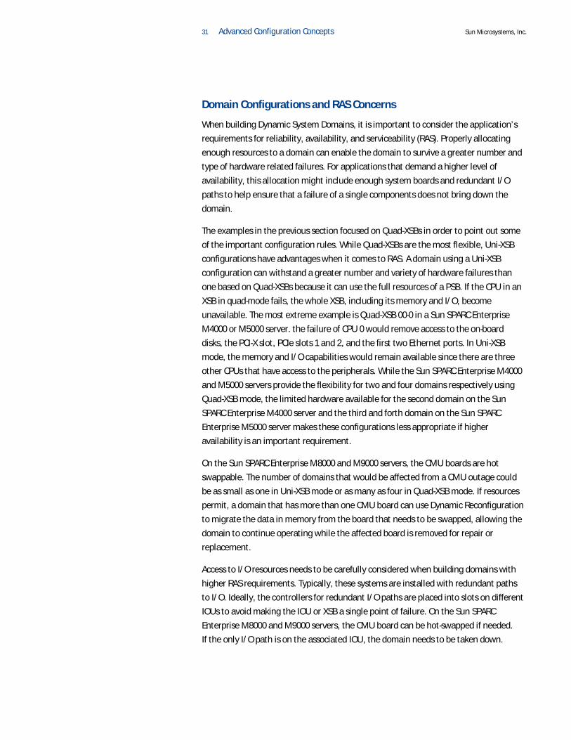
Domain Configurations and RAS Concerns
When building Dynamic System Domains, it is important to consider the application’s
requirements for reliability, availability, and serviceability (RAS). Properly allocating
enough resources to a domain can enable the domain to survive a greater number and
type of hardware related failures. For applications that demand a higher level of
availability, this allocation might include enough system boards and redundant I/O
paths to help ensure that a failure of a single components does not bring down the
domain.
The examples in the previous section focused on Quad-XSBs in order to point out some
of the important configuration rules. While Quad-XSBs are the most flexible, Uni-XSB
configurations have advantages when it comes to RAS. A domain using a Uni-XSB
configuration can withstand a greater number and variety of hardware failures than
one based on Quad-XSBs because it can use the full resources of a PSB. If the CPU in an
XSB in quad-mode fails, the whole XSB, including its memory and I/O, become
unavailable. The most extreme example is Quad-XSB 00-0 in a Sun SPARC Enterprise
M4000 or M5000 server. the failure of CPU 0 would remove access to the on-board
disks, the PCI-X slot, PCIe slots 1 and 2, and the first two Ethernet ports. In Uni-XSB
mode, the memory and I/O capabilities would remain available since there are three
other CPUs that have access to the peripherals. While the Sun SPARC Enterprise M4000
and M5000 servers provide the flexibility for two and four domains respectively using
Quad-XSB mode, the limited hardware available for the second domain on the Sun
SPARC Enterprise M4000 server and the third and forth domain on the Sun SPARC
Enterprise M5000 server makes these configurations less appropriate if higher
availability is an important requirement.
On the Sun SPARC Enterprise M8000 and M9000 servers, the CMU boards are hot
swappable. The number of domains that would be affected from a CMU outage could
be as small as one in Uni-XSB mode or as many as four in Quad-XSB mode. If resources
permit, a domain that has more than one CMU board can use Dynamic Reconfiguration
to migrate the data in memory from the board that needs to be swapped, allowing the
domain to continue operating while the affected board is removed for repair or
replacement.
Access to I/O resources needs to be carefully considered when building domains with
higher RAS requirements. Typically, these systems are installed with redundant paths
to I/O. Ideally, the controllers for redundant I/O paths are placed into slots on different
IOUs to avoid making the IOU or XSB a single point of failure. On the Sun SPARC
Enterprise M8000 and M9000 servers, the CMU board can be hot-swapped if needed. If the only I/O path is on the associated IOU, the domain needs to be taken down.

32 Advanced Configuration Concepts Sun Microsystems, Inc.
Advanced Memory ConfigurationThe earlier chapter on basic configuration covered the big rules that help avoid
configuration mistakes and provide functional configurations. This section covers
additional features such as memory mirroring and adding DIMMs of different densities.
Memory Configuration Rules
It is helpful to review the memory rules already covered:
1. On the Sun SPARC Enterprise M4000 or M5000 servers, three MEMBs is not a valid
configuration, there must be 1, 2, or 4 per PSB.
2. The Sun SPARC Enterprise M8000 or M9000 server CMU board can either be half
populated with 16 DIMMs or fully populated with 32 DIMMs.
3. The Sun SPARC Enterprise M4000 or M5000 server MEMB can either be half popu-
lated with 4 DIMMs in Group A or fully populated with 8 DIMMs filling both Group
A and B.
4. Memory on the Sun SPARC Enterprise M8000 or M9000 server CMU boards is orga-
nized into two groups of 16 DIMMs, Group A and Group B. Group A must be always
populated.
5. Memory groups must be filled with identical DIMMs. All DIMM should have the
same Sun part number.
6. MEMBs must be populated identically within an XSB.
7. Every XSB must have both CPU and memory.
The memory requirements for Uni-XSBs and Quad-XSBs differ. It is possible to have a
valid Uni-XSB configuration that is invalid for Quad-XSB mode and vice-versa. An example of this would be not having enough MEMBs to provide all installed CPUs
with memory once in quad mode.
Adding DIMMs with Different CapacitiesThe Sun SPARC Enterprise M-series servers can accept 1, 2, or 4 GB DIMMs. There are a
number of requirements that dictate that the DIMM sizes to be consistent. Several of
the base configurations start with 1 GB DIMMs. Utilizing only 1 GB DIMMs limits the
maximum memory size of the server to a quarter of the total capacity. In order to use
higher capacity DIMMs without having to discard the existing DIMMs, the M-series
servers allow different sized DIMMs to be used if some additional rules are carefully
followed.
Larger capacity DIMMs must be placed in group A. Since Group A must be populated
first, this means that the smaller DIMMs in group A need to be moved to group B,
which would allow the new, larger DIMMs to be installed into the group A slots. Sun recommends that these tasks are only performed by Sun Service professionals.
33 Advanced Configuration Concepts Sun Microsystems, Inc.
Recall that the DIMMs within a group need to be identical, (they should all have the
same Sun part number), and that the memory configuration across a PSB must be
consistent. For a Sun SPARC Enterprise M8000 or M9000 server CMU, these rules
require changing 16 DIMMs at a time. The number of DIMMs affected for a Sun SPARC
Enterprise M4000 or M5000 server depends on the number of MEMBs installed. If four
MEMBs are installed on PSB 0, then all four need to be upgraded identically, requiring
16 DIMMs, 4 for each MEMB. If only two MEMB are installed, then only 8 new DIMMs
are needed to upgrade the 4 DIMMs on each MEMB.
To illustrate the rules above, here are several examples of adding higher capacity
DIMMs to a Sun SPARC Enterprise M4000 or M5000 server. The base configuration
includes one CPUM (which includes two CPUs) and 8 GB of memory in two MEMBs.
Each MEMB has four 1 GB DIMMs installed in the first group, Group A. The DIMM slots
for Group B are empty. The base configuration for the Sun SPARC Enterprise M5000
server is the same, however there is a second PSB that has no CPU or memory installed.
Using only 1 GB DIMMs, the system could only go to 16 GB before additional MEMBs
are needed.
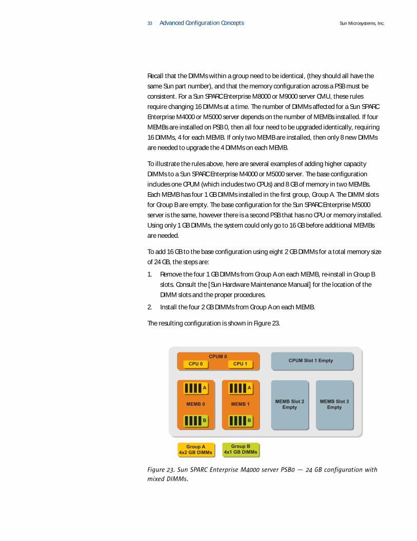
To add 16 GB to the base configuration using eight 2 GB DIMMs for a total memory size
of 24 GB, the steps are:
1. Remove the four 1 GB DIMMs from Group A on each MEMB, re-install in Group B
slots. Consult the [Sun Hardware Maintenance Manual] for the location of the
DIMM slots and the proper procedures.
2. Install the four 2 GB DIMMs from Group A on each MEMB.
The resulting configuration is shown in Figure 23.
MEMB Slot 3Empty
MEMB Slot 2Empty
CPUM Slot 1 Empty
MEMB 0
A
B
MEMB 1
A
B
CPUM 0
Group A4x2 GB DIMMs
Group B4x1 GB DIMMs
CPU 0 CPU 1
Figure 23. Sun SPARC Enterprise M4000 server PSB0 — 24 GB configuration with
mixed DIMMs.

34 Advanced Configuration Concepts Sun Microsystems, Inc.
To add memory without discarding any DIMMs, additional MEMBs are needed. Given
the memory configuration rules, the next step is to add another two MEMBs configured
identically to the first two MEMBs, with four 2 GB DIMMs in Group A, and four 1 GB
DIMMs in Group B. Three MEMBs is not a valid configuration so two must be added. All MEMBs on a PSB must be identical, not only in total memory but identical DIMMs,
so the two additional MEMBs must match. The resulting configuration is shown in
Figure 24.
MEMB 0
A
B
MEMB 1
A
B
MEMB 2
CPUM 0
A
B
CPU 0 CPU 1
MEMB 3
A
B
CPUM Slot 1 Empty
Group A4x2 GB DIMMs
Group B4x1 GB DIMMs
Figure 24. Sun SPARC Enterprise M4000 server, PSB 0 — 48 GB configuration with
mixed DIMMs.
The maximum memory per system board on the Sun SPARC Enterprise M4000 or M5000
servers using 4 GB DIMMs is 128 GB. The rule requiring that MEMBs be identical applies
to the XSB. On the Sun SPARC Enterprise M5000 server, there are two Uni-XSBs
packaged into a single motherboard, as illustrated in Figure 4 on page 6. The MEMBs in
slots 0-3 must be identical, and the MEMBs in slots 4-7 must be identical. However, the
two groups do not have to be identical. Figure 25 below shows a valid Sun SPARC
Enterprise M5000 configuration with different MEMB sizes on each XSB.

35 Advanced Configuration Concepts Sun Microsystems, Inc.
PSB 124 GB
2 MEMB
Group A4x2 GB DIMMs
Group B4x1 GB DIMMs
MEMB Slot 7Empty
MEMB Slot 6EmptyMEMB 4
A
B
MEMB 5
A
B
CPU 4 CPU 5
Group A4x4 GB DIMMs
Group B4x4 GB DIMMs
PSB 0128 GB
4 MEMB8 x 4GB
MEMB 0
A
B
MEMB 1
A
B
MEMB 2
CPUM 0
A
B
CPU 0 CPU 1
MEMB 3
A
B
CPUM Slot 1 Empty
CPUM Slot 3 EmptyCPUM 2
Figure 25. Sun SPARC Enterprise M5000 server, different MEMB configurations on
PSB 0 and 1.
Memory Mirroring Configurations
The Sun SPARC Enterprise M-series servers use Extended-Error Correcting Code (ECC)
memory that can correct memory errors up to one bit and detect errors up to two bits.
For even higher reliability, data can be written to two different sets of memory. On reads, both sets of memory are read and compared. If an uncorrectable error occurs
while reading from one set of memory, the data from the other set is then used. This
level of protection uses twice the amount of memory for the same volume of data.
Memory mirroring is completely transparent to the operating system and applications
since the mirroring occurs in hardware. The performance impact of enabling memory
mirroring is negligible.
In order to properly configure memory mirroring it is important to understand where
the mirroring occurs on each system. On the Sun SPARC Enterprise M4000 and M5000
servers, the memory is mirrored within the MEMB module itself. Data is mirrored
between the DIMMs of each group, as shown in Figure 26. The requirement for memory

36 Advanced Configuration Concepts Sun Microsystems, Inc.
mirroring is that both groups A and B are populated with identical DIMMs. There is a
Memory Access Controller (MAC) ASIC on each MEMB that performs the mirroring.
Memory mirroring can be used in either Uni-XSB or Quad-XSB mode.
Mirror
4 DIMMs
4 DIMMs
MAC
Group A
Group B
Figure 26. Sun SPARC Enterprise M4000 or M5000 server MEMB — memory
mirroring.
On the Sun SPARC Enterprise M8000 and M9000 servers, memory is also mirrored
across banks. Therefore, all 32 DIMMs on the CMU must be populated identically.
Memory mirroring can only be used in Uni-XSB mode due to the way memory is striped
on these systems.
I/O Performance ConsiderationsThis section contains several I/O performance-related configuration tips. System
performance is a far broader topic than can be covered in this article. The following
recommendations help I/O throughput.
PCIe Slot UtilizationOn the Sun SPARC Enterprise M4000 and M5000 servers, for performance reasons, it is
best to use the highest numbered PCIe first and then work downward (e.g., 3,2,1.). The last slot that should be utilized when all other slots are full is slot 1, since it shares
resources with PCI-X slot 0, as well as the on-board controllers for Ethernet and internal
SAS disks. Note that using Quad-XSB mode restricts the available slots for each XSB.
However, the rule to use the highest number slots first still applies.
The rule for deciding which PCIe cards should go in the highest numbered slots is based
on which card has the highest throughput requirements. On systems that have
requirements for high disk I/O operations (e.g., database servers), the disk controller
cards should go in the highest numbered slots. Ten gigabit Ethernet cards are another
example of a high-throughput card that should be given preference for higher
numbered slots.
On the Sun SPARC Enterprise M8000 and M9000 servers, the even numbered PCIe slots
should be filled first. The odd numbered slots should not be filled until the even
numbered slots are filled. This is due to the shared resources between each pair of PCIe

37 Advanced Configuration Concepts Sun Microsystems, Inc.
slots, 0 and 1, 2 and 3, and so on. If the odd slots need to be utilized then the lowest
throughput cards should be put in the odd numbered slots that are shared with the
highest throughput cards.
PCIe Relaxed Ordering
PCIe relaxed ordering allows the system to obtain the best performance from PCIe I/O.
Relaxed ordering comes into play when there are multiple PCIe bus transactions
occurring simultaneously. With strict ordering, PCIe bus transactions must complete in
the same order as they are originally requested. Slower transactions can block other
transactions that could run in parallel until the earlier, slower transaction completes.
The degree of impact relaxed ordering has on throughput depends on the size of the
system. Larger systems benefit the most. An example of a slower transaction is a PCIe
card on one XSB that needs to store incoming data in memory on a different XSB,
which requires the data to go across the system’s backplane.
Enabling relaxed ordering requires certain minimum levels of firmware and system
software. In addition, device drivers need to correctly handle relaxed ordering. High
throughput devices such as disk controllers and network interfaces are the most
critical. Therefore, in order to take advantage of PCIe relaxed ordering, it is
recommended that all system software is up-to-date, including any recommended
patches. Additionally, the availability of patches should be checked for all PCIe cards
installed in the system.

38 Software Notes Sun Microsystems, Inc.
Chapter 4
Software Notes
Up-to-date system software is vital for proper operation of the Sun SPARC Enterprise M-series servers. The software components consist of the Sun Solaris™ Operating
System (Solaris OS), as well as firmware including the Open Boot PROM (OBP), Power-
On Self-Test (POST), and the eXtended System Control Facility (XSCF), which runs on the
systems service processor(s). The firmware is supplied in a package called the XCP (XSCF
Control Package).
Sun recommends that the system software and firmware be kept up-to-date with the
latest released versions, which often contain the latest fixes that are critical for proper
operation. Installing or upgrading new system components might also require that the
latest system software be installed in order to support any new versions of the
hardware components. Refer to the product notes that accompany each release for any
late breaking software and hardware notes.
XSCF UnitsThe Sun SPARC Enterprise M-series servers include one or two service processors that
function as dedicated hardware for managing and configuring the server. The service
processor units are referred to as the XSCFU (eXtended System Control Facility Units).
The XSCFU operate independently of the server and can be used to perform functions
such as controlling power-on and power-off of components. The full cabinet-sized
servers includes two XSCFU for redundancy. The system software for the service
processor is the XSCF. The XSCF is kept up-to-date by installing the latest release of the
XCP.
The XSCFU provides both a serial console port and an Ethernet port, allowing for both a
direct console connection and remote management over the network. Some XSCF
functionality, such as email alerts, only work over a network connection. Therefore,
Sun recommends that the XSCFU is always connected to a network. The XSCFU network
connection is completely independent from any of the networks connected to the XSBs.
As such, a network connection to an XSB does not provide any connectivity to the
XSCFU.
XSCFU FunctionalityThe XSCFU provides a command-line interface as well as a browser-based user
interface. Through these interfaces the hardware resources can be controlled,
configured, and monitored locally or remotely. Much of the system configuration
discussed in this article is performed through the XSCFU. Detailed reports are available
to show the current system configuration. These reports also indicate if there are
components that cannot be utilized due to misconfiguration.

39 Software Notes Sun Microsystems, Inc.
Dynamic System Domains are managed through the XSCFU. Hardware resources can be
grouped into domains. Domains can be started and stopped. The XSCFU also provides
the Dynamic Reconfiguration function that allows domains to be changed during
operation. This provides the capability to dynamically configure system resources as
needed.
The XSCFU constantly monitors the system for any hardware failures. Errors are
recorded in the hardware logs and analyzed to determine the location of the fault.
The XSCFU comes with a number of features to improve security. In order to access the
XSCFU a user account with a password is required. The software enables individual user
accounts with different privilege levels to be created. The privileges can be assigned to
limit access to only the specific functionality required by a given user. An audit facility
can be enabled to provide to logs of XSCFU activity.
In order to allow secure remote access to the XSCFU, command-line access can be
encrypted over the network by using the Secure Shell (SSH). Using the telnet protocol
for remote access is strongly discouraged since it lacks encryption capabilities. Secure
browser access is provided by using HTTPS connections that utilize the Secure Sockets
Layer (SSL) to encrypt network traffic. Unencrypted HTTP is available, however its use is
also strongly discouraged. Given that the XSCFU network connection is completely
independent from any of the XSBs, the XSCFU can be connected to a separate
administrative network for improved security.
Email Alerts
The Sun SPARC Enterprise M-series servers’ XSCFU can be configured to send email
alerts when critical events such as a hardware failure occur. It is strongly
recommended that email alerts be enabled on all systems to help ensure that the
appropriate people are notified as quickly as possible.
The XSCF must be connected to a network in order to transmit email alerts. The XSCF
network connection also allows remote administration, log archiving, and firmware
updates. Log archiving should be enabled to save system log files as they grow in size.
XCP Software Versions
The XCP contains the necessary firmware required to properly operate the XSCFU and
the server components at a very low level. Sun recommends that the latest version of
the XCP be used at system installation time. This is particularly important since the
latest XCP release might contain updates to support the most recent revisions of the
hardware components used to build the system. At no point should the XCP software
be downgraded to a previous version. Installing or upgrading components might
require upgrading the XCP. For example, the use of SPARC VII quad-core CPUs requires a

40 Software Notes Sun Microsystems, Inc.
minimum of XCP 1070 in order to operate. A best practice is to regularly check for
newer versions of the XCP software, as new versions are periodically released and can
contain important fixes.
Solaris™ OS Compatibility
Solaris 10 05/08, or later, is strongly recommended for Sun SPARC Enterprise M-series
servers. If this version cannot be utilized, the minimum release of the Solaris OS
depends on the CPUs that are installed in the system. SPARC64 VII quad-core CPUs
requires a minimum of Solaris 10 8/07 with the addition of mandatory patches. If only
SPARC64 VI CPUs are used then the minimum version is Solaris 10 11/06, also with the
application of mandatory patches. This is summarized in Table 6.
Table 6.
SPARC64 VI only Solaris 10 11/06 (with mandatory patches)
SPARC64 VII Solaris 10 8/07 (with mandatory patches)
Minimum versions of the Solaris Operating System.
Required Solaris Packages
Table 7 lists the Solaris packages that are required for proper operation of the Sun
SPARC Enterprise M-series servers. These packages are for system management
facilities such as communications between the domain and the XSCF. Additionally, the
services related to these packages must be enabled within the operating system to take
affect.
Table 7.
SUNWdscpr, SUNWdscpu Domain-to-service processor communications protocol.
SUNWppp, SUNWpppd, SUNWpppdr, SUNWpppdu, SUNWpppdt
Point to Point Protocol (PPP), device drivers, configuration files, tunnelling extensions, daemons, and utilities. Implements IP networking between domain and XSCF using PPP.
SUNWsckm, SUNWsckmr, SUNWsckmu
Key management facilities for exchanging encryption keys with the service processor.
Required Solaris packages.
CPUs Solaris Release
Package Description
41 Summary Sun Microsystems, Inc.
Chapter 5
Summary
The Sun SPARC Enterprise M-series server line offers a great deal of configuration
flexibility in addition to high performance and reliability. The configuration flexibility
presents a number of options that must be carefully considered. Configuration
mistakes can be avoided by understanding the configuration rules and how
components are connected within the system. This article described the major
components including the extended system board, which is the key building block of
the system. Basic configuration examples are presented to illustrate most typical
installations. This article also covers advanced configuration topics such as Quad-XSBs,
Dynamic System Domains, and memory mirroring.
About the AuthorJames Hsieh is a Staff Engineer with Sun's Systems Group responsible for the Sun
SPARC Enterprise server line. Prior to his current role, James was a member of Sun's
Technology Service Center (TSC) providing advanced support for Sun's mid-range server
line and a member of Sun Services supporting mission critical customers. Prior to Sun,
James worked for over 13 years with UNIX® and Sun systems as a software engineer
and as a systems administrator for large groups of UNIX systems.
AcknowledgementsThe author would like to acknowledge Robert Terzi for his contributions to this article.
His insights and perspectives were especially valuable in organizing and presenting the
content.
References
Sun Microsystems, Sun SPARC Enterprise M4000 Server — Hardware Documentation, http://docs.sun.com/app/docs/coll/m4000-hw
Sun Microsystems, Sun SPARC Enterprise M5000 Server — Hardware Documentation, http://docs.sun.com/app/docs/coll/m5000-hw
Sun Microsystems, Sun SPARC Enterprise M8000 Server — Hardware Documentation, http://docs.sun.com/app/docs/coll/m8000-hw
Sun Microsystems, Sun SPARC Enterprise M8000 Server — Hardware Documentation, http://docs.sun.com/app/docs/coll/m9000-hw

42 Summary Sun Microsystems, Inc.
The hardware documentation for the Sun SPARC Enterprise M-series servers listed
above includes the following server specific documents that are referenced in this Sun
Blueprints article:
• Sun SPARC Enterprise Mx000 Server Overview Guide
• Sun SPARC Enterprise Mx000 Server Site Planning Guide
• Sun SPARC Enterprise Mx000 Server Installation Guide
• Sun SPARC Enterprise Mx000 Server Product Notes
• Sun SPARC Enterprise M4000 and M5000 Servers Rackmount Guide
Related Resources
Sun Microsystems, Sun SPARC Enterprise M4000, M5000, M8000, and M9000 Server
Architecture, http://www.sun.com/servers/sparcenterprise/SPARCEnt-Arch-
Final.pdf
Kloski, Nick. “Introduction to Dynamic Reconfiguration and Capacity on Demand for
Sun SPARC Enterprise Servers,” Sun BluePrints Online, April 2007, To access this article
online, go to: http://wikis.sun.com/display/BluePrints/Introduction+to+Dyn
amic+Reconfiguration+and+Capacity+on+Demand+for+Sun+SPARC+E
nterprise+Servers
Ordering Sun DocumentsThe SunDocsSM program provides more than 250 manuals from Sun Microsystems, Inc.
If you live in the United States, Canada, Europe, or Japan, you can purchase
documentation sets or individual manuals through this program.
Accessing Sun Documentation OnlineThe docs.sun.com Web site enables you to access Sun technical documentation
online. You can browse the docs.sun.com archive or search for a specific book title
or subject. The URL is http://docs.sun.com/
To reference Sun BluePrints Online articles, visit the Sun BluePrints Online Web site at: http://www.sun.com/blueprints/online.html

Sun SPARC Enterprise M-Series Configuration Concepts On the Web sun.com
Sun Microsystems, Inc. 4150 Network Circle, Santa Clara, CA 95054 USA Phone 1-650-960-1300 or 1-800-555-9SUN (9786) Web sun.com
© 2008 Sun Microsystems, Inc. All rights reserved. Sun, Sun Microsystems, the Sun logo, Sun Blueprints, Solaris, and Sun Fire are trademarks or registered trademarks of Sun Microsystems, Inc. or its subsidiaries in
the United States and other countries. All SPARC trademarks are used under license and are trademarks or registered trademarks of SPARC International, Inc. in the U.S. and other countries. Products bearing SPARC
trademarks are based upon architecture developed by Sun Microsystems, Inc. UNIX is a registered trademark in the United States and other countries, exclusively licensed through X/Open Company, Ltd.
Information subject to change without notice. Printed in USA 12/08


![Sun SPARC Enterprise M3000Server Architecture1].pdf · Sun SPARC Enterprise servers offer improved performance over the previous generations of Sun servers, ... The XCP enables audit](https://static.fdocuments.us/doc/165x107/5af441697f8b9a92718d532c/sun-sparc-enterprise-m3000server-1pdfsun-sparc-enterprise-servers-offer-improved.jpg)