Sun Sensor - PW-Sat · PW-Sat2 Critical Design Review 2016-11-30 Sun Sensor Phase C pw-sat.pl 5 of...
40
STUDENTS’ SPACE ASSOCIATION THE FACULTY OF POWER AND AERONAUTICAL ENGINEERING WARSAW UNIVERSITY OF TECHNOLOGY CRITICAL DESIGN REVIEW Sun Sensor November 2016 Issue no. 1
Transcript of Sun Sensor - PW-Sat · PW-Sat2 Critical Design Review 2016-11-30 Sun Sensor Phase C pw-sat.pl 5 of...
STUDENTS’ SPACE ASSOCIATION
THE FACULTY OF POWER AND AERONAUTICAL ENGINEERING
WARSAW UNIVERSITY OF TECHNOLOGY
CRITICAL DESIGN REVIEW
Sun Sensor
November 2016
Issue no. 1

PW-Sat2 Critical Design Review
2016-11-30 Sun Sensor
Phase C
pw-sat.pl
1 of 39
Changes
Date Changes Pages/Section Responsible
2016-11-30 First issue of the document -
ch. 2, 3, 8, 9
ch. 2
ch. 3, 8
ch. 5
ch. 8
ch. 4, 6
-
Michał Gumiela
Mateusz Sobiecki
Kamil Sażyński
Grzegorz
Ambroszkiewicz
Bartosz Kaczor
Szymon Polak
Grzegorz Gajoch
Dominik Roszkowski
Published by
Students’ Space Association
Warsaw University of Technology, 2016
This work is licensed on CC BY-NC 3.0
Project logo by Krzysztof Karaś
Quote as: PW-Sat2 Team, Phase C Documentation – Critical Design Review – Sun Sensor, Students’ Space
Association, Warsaw University of Technology, pw-sat.pl 2016

PW-Sat2 Critical Design Review
2016-11-30 Sun Sensor
Phase C
pw-sat.pl
2 of 39
Table of contents
1 Introduction 6
1.1 Purpose and Scope .................................................................................................................................... 6
1.2 Document Structure .................................................................................................................................. 6
1.3 Project Documentation Structure .............................................................................................................. 6
1.4 Reference Documents ............................................................................................................................... 6
1.5 Document Contributors ............................................................................................................................. 6
2 System Description 7
2.1 System requirements ................................................................................................................................. 7
2.2 Last changes .............................................................................................................................................. 7
3 Mechanical Design 9
3.1 Case Design .............................................................................................................................................. 9
3.2 Integration Process .................................................................................................................................. 10
4 Electronics Design 12
4.1 Changes Description ............................................................................................................................... 12
4.1.1 Digital light intensity sensors .......................................................................................................... 12
4.1.2 Compact main board ....................................................................................................................... 13
4.2 System Diagram ...................................................................................................................................... 14
4.3 Description of operation .......................................................................................................................... 16
4.3.1 Light intensity measurement ............................................................................................................ 16
4.3.2 Temperature measurement .............................................................................................................. 21
4.3.3 Microcontroller unit ........................................................................................................................ 23
4.3.4 FRAM Memory ................................................................................................................................ 24
5 Sensor computing algorithm 25
5.1 General assumptions ............................................................................................................................... 25
5.2 Description .............................................................................................................................................. 25
5.2.1 Dependent Signals ........................................................................................................................... 25
5.2.2 Training network ............................................................................................................................. 26
5.2.3 Export code ..................................................................................................................................... 27
5.3 Theoretical results ................................................................................................................................... 27
6 MCU Embedded software 30
6.1 General description ................................................................................................................................. 30
6.2 Communications via I2C ......................................................................................................................... 30

PW-Sat2 Critical Design Review
2016-11-30 Sun Sensor
Phase C
pw-sat.pl
3 of 39
6.3 Commands and registers ......................................................................................................................... 30
7 Sun Sensor prototype 32
8 Testing 34
8.1 Test Stand................................................................................................................................................ 34
8.1.1 Light source ..................................................................................................................................... 34
8.1.2 Rotating table .................................................................................................................................. 35
8.2 Required tests description ....................................................................................................................... 36
8.2.1 Functional tests ............................................................................................................................... 36
8.2.2 Thermal test ..................................................................................................................................... 36
8.2.3 Vacuum test ..................................................................................................................................... 37
8.2.4 Vibration test ................................................................................................................................... 37
8.3 Test Plan.................................................................................................................................................. 37
8.4 Test results and system verification ........................................................................................................ 37
9 On orbit operation 38
9.1 Operating plan ......................................................................................................................................... 38
9.2 Required data and Data Rate ................................................................................................................... 38
9.3 On orbit system verification description ................................................................................................. 39

PW-Sat2 Critical Design Review
2016-11-30 Sun Sensor
Phase C
pw-sat.pl
4 of 39
List of figures
Figure 3-1 Sun Sensor case design. .......................................................................................................................................... 10 Figure 3-2 Sun Sensor case assembly ....................................................................................................................................... 11 Figure 4-1 Module (a small PCB) with three digital ALS replacing an analog photovoltaic panel. ......................................... 12 Figure 4-2 Panels with ALS sensors and RTD thermometers. ................................................................................................. 13 Figure 4-3 Main, 4-layer printed circuit board with dimensions. ............................................................................................. 13 Figure 4-4 The main board of the SunSensor. .......................................................................................................................... 14 Figure 4-5 Sun Sensor architecture diagram............................................................................................................................. 15 Figure 4-6 Render of the Sun Sensor. ....................................................................................................................................... 15 Figure 4-7 Light sensors grouped into three sets of four. ......................................................................................................... 16 Figure 4-8 BH1730FVC ALS internal architecture. ................................................................................................................. 17 Figure 4-9 Connection of four sensors to microcontroller (one ‘set’). ..................................................................................... 18 Figure 4-10 Groups of redundant ambient light sensors. .......................................................................................................... 19 Figure 4-11 Calibration characteristic for visible light photodiode in the ALS. ....................................................................... 20 Figure 4-12 Calibration characteristic for infrared photodiode in the ALS. ............................................................................. 20 Figure 4-13 PT1000 RTD platinum sensor in SMD 0805 package. ......................................................................................... 21 Figure 4-14 RTD platinum sensor readout circuit architecture. ............................................................................................... 22 Figure 4-15 Analog interface for RTDs.................................................................................................................................... 22 Figure 4-16 Resolution of temperature measurement with PT1000 RTDs. .............................................................................. 23 Figure 5-1: Structure of neural network used for approximation.............................................................................................. 25 Figure 5-2: presentation of R1 in polar coordinates. ................................................................................................................ 26 Figure 5-3: Error for elevation determining in every test point. ............................................................................................... 27 Figure 5-4: Error for elevation determining in every test point. ............................................................................................... 28 Figure 5-5: Error for rotation determining in every test point. ................................................................................................. 28 Figure 5-6: Error for rotation determining in every test point. ................................................................................................. 29 Figure 7-1 A picture of the SunSensor prototype during assembly. ......................................................................................... 32 Figure 7-2 A picture of the SunSensor prototype during assembly. ......................................................................................... 33
List of tables
Table 3-1 Sun Sensor part list. ................................................................................................................................................... 9 Table 4-1 BH1730FVC sensor specification. ........................................................................................................................... 17 Table 6-1 Register map of the SunS ......................................................................................................................................... 30

PW-Sat2 Critical Design Review
2016-11-30 Sun Sensor
Phase C
pw-sat.pl
5 of 39
Abbreviated terms
ADCS Attitude Determination and Control System
COMM Communication subsystem
DT Deployment Team
EM Engineering Model
EPS Electrical Power System
ESA European Space Agency
FM Flight Model
GS Ground Station
LEO Low Earth Orbit
MA Mission Analysis
MCU Mission Controller Unit
MDR Mission Definition Review
PDR Preliminary Design Review
PV Photovoltaic cell
RTD Resistance Thermal Detector
SC Spacecraft
SKA Studenckie Koło Astronautyczne (Students’ Space Association)
Sps Samples per second
SSO Sun-Synchronous Orbit
SW Software
TBC To Be Continued
TBD To Be Defined
TCS Thermal Control System
WUT Warsaw University of Technology

PW-Sat2 Critical Design Review
2016-11-30 Sun Sensor
Phase C
pw-sat.pl
6 of 39
1 INTRODUCTION
1.1 PURPOSE AND SCOPE
The aim of the Sun Sensor experiment, as it was in the earlier phases, is to build and to test the performance of the
Sun Sensor working on board of the satellite. The Sun Sensor will be two-axis device, with possibly small
dimensions and sufficient accuracy (better than photodiodes), in order to create a low-cost sensor for CubeSat
missions.
1.2 DOCUMENT STRUCTURE
Chapter 1 introduces the document and its structure.
Chapter 2 describes the Sun Sensor (SunS) from the system point of view.
Chapter 3 summarizes mechanical design of the SunS.
Chapter 4 presents electronics design of the SunS.
Chapter 5 describes computing algorithm of the sensor.
Chapter 6 describes embedded software on Mission Controller Unit of SunS.
Chapter 7 presentes the SunS prototypes.
Chapter 8 prestents the tests philosophy of the SunS.
1.3 PROJECT DOCUMENTATION STRUCTURE
See section 1.3 in [PW-Sat2-C-00.00-Overview-CDR].
1.4 REFERENCE DOCUMENTS
Internal project documents are referred by its name according to the [PW-Sat2-C-00.00-Overview-CDR].
1.5 DOCUMENT CONTRIBUTORS
This document and any results described were prepared solely by PW-Sat2 project team members.

PW-Sat2 Critical Design Review
2016-11-30 Sun Sensor
Phase C
pw-sat.pl
7 of 39
2 SYSTEM DESCRIPTION
2.1 SYSTEM REQUIREMENTS
The system requirements are the same as prepared in the phase B:
Small dimensions – less than 1U wall with depth <20mm;
Relatively wide field of view – 120°-160° on two axes;
Sensor accuracy – as good, as it is possible, 0.1°-5°;
Sensor structure easy to produce and relatively cheap;
Using commercial off-the-shelf components;
Low power consumption – less than 0.5W.
This is how a Table should look like. It may have horizontal lines in the table body, but you can do them also like
in Table B-1.
2.2 LAST CHANGES
In the earlier phase there was considered design based on photovoltaic cells, fully analog devices. Due to many
issues discussed later in this chapter (some of them were also mentioned in phase B document [PW-Sat2-B-06.00-
SunS-PDR]), a decision was made to replace them with the digital components, the ALS (Ambient Light Sensors),
which are smaller and easier for signal measurement than photovoltaic cells and photodiodes.
There were many problems with the photovoltaic cells. First of all, cutting of the cells to their final size was hard
and only the diamond wire cutting gave sufficient results. Mounting cells to the PCB boards, due to their fragility,
wasn’t reliable and cells could be easily broken during the subsequent use of the sensor. Also the electronics
required for the analog signals reading was quite extended. Still the readings have depended on the temperature
changes. Such device based on the photovoltaic cells required a lot of additional work to do and the expected
results could not be sufficient. Due to the described causes, there were made a decision to replace the cells with
the Ambient Light Sensors. Such sensors are similar to the photodiodes, but they have a built-in current-integrating
amplifier and analog to digital converter (ADC). This gives the possibility to achieve better performance than with
photodiodes, as well as with solar cells. There were chosen the BH1730 sensors.
One of the important objectives part of the project was the size of the detector. With the selection of the digital
BH1730 in the role of solar light sensor, it is possible to place 12 of these elements in the device, instead of four
solar cells, giving the redundancy of the measurement. And still the final size of the device allows for mounting
on the Cubesat wall.
The system consisting of the BH1730 will be made at low cost. There is expected correct operation of the whole
device based of the angle tests and temperature tests. Performance of the photovoltaic has also been defined as
correct, however, the requirement for small usable space, the need for make precisely cutting the solar cells and
the need to implement an extended electronic system with temperature compensation algorithm, the design with
the photovoltaic cells has been replaced.

PW-Sat2 Critical Design Review
2016-11-30 Sun Sensor
Phase C
pw-sat.pl
8 of 39
New design of the SunSensor is based on the examination of digital integrated light sensors, which feature a simple
communication with the microcontroller and easy mechanical implementation. There were tested three sensors:
TSL2561T, BH1751FVI, BH1730FVC. Basing on the test results, BH1730FVC was selected to work in the
SunSensor. The small dimensions of the sensor and the surface provided for mounting the photocell enable to
mount three such sensors and a temperature sensor. This provides redundancy and greater reliability of results than
in the case of photovoltaic cells.
Although the ALS sensors still exhibit significant temperature dependence on light readings, there is enough space
on the SunSensor board to equip the device with platinum resistance thermometers to compensate unwanted
temperature influence.
The selected sensors show a sufficiently high angular resolution, and thanks to the digital form of data will be
possible to quickly obtain information about the orientation of the expected accuracy of the location close to 1 °.
Systems have a temperature compensation, but it’s functionality is not ideal. The system selected have the
temperature compensation function the closest to the linear over the entire range, so that it will be possible to
eliminate additional control system.
The activities carried out, which resulted in the choice are presented in the thesis under the title 'Project of detector
of optimal position to solar radiation in satellite PW-Sat2', whose author is a member of the PW-Sat2 team.

PW-Sat2 Critical Design Review
2016-11-30 Sun Sensor
Phase C
pw-sat.pl
9 of 39
3 MECHANICAL DESIGN
Sun Sensor’s mechanical design needs to fulfill all space requirements and provide proper angular alignment of
sensors. Selected materials, connections and dimensions shall ensure resistance to vibration loads during launch.
In this section there are presented the mechanical aspects - mainly sensors mounting and integration.
3.1 CASE DESIGN
Sun Sensor’s case design is based on a pyramid shape. Four PCB’s with sensors are placed separately,
perpendicularly to each other. Electronics mounting is simple and tilted 20 degrees so there is no shadow caused
by screening elements that could affect sensor read-outs. Sun Sensor’s design is compact (56x56x8 mm) and
ensures enough space for other subsystems. Case geometric shape is to reduce the number of elements. Device
consists of 28 parts presented in table 3-1. All external surfaces of aluminum parts are anodized.
Table 3-1 Sun Sensor part list.
No Name Quantity Material Comments
1 Case 1 Aluminium 7075 Anodized
2 Cover 1 Aluminium 7075 Anodized
3 Spacer 4 Delrin/PEEK
4 Screw ISO 10642 M2x8 4 A4
5 Screw ISO 10642 M1,6x4 8 A4
6 Nut ISO 4035 M2 4 A4
7 Mainboard 1 FR4+electronics
8 Sensor PCBs with 9 cables 4 FR4+electronics
9 Cables with connector 1x4wires
28
There are few things, that decided about the design of the case. The idea is to have the easy mounting of the
electronic boards. The case is an aluminum milled part and PCB boards with sensors can be fixed with proper
angle, without shadowing of the sensor’s detector area. The Main Board is in the center of the system, to have a
short connection with the sensors. Creating the one piece element for mounting the boards simplifies the integration
process and ensures the proper alignment. The height of the system is to be low, to fit the Cubesat standard to have
elements at maximum of 6.5mm distance over the Cubesat rails surface and not to disturb in the space inside of
the satellite with placing other standard components. The design pictures are presented below.
PW-Sat2 Critical Design Review
2016-11-30 Sun Sensor
Phase C
pw-sat.pl
10 of 39
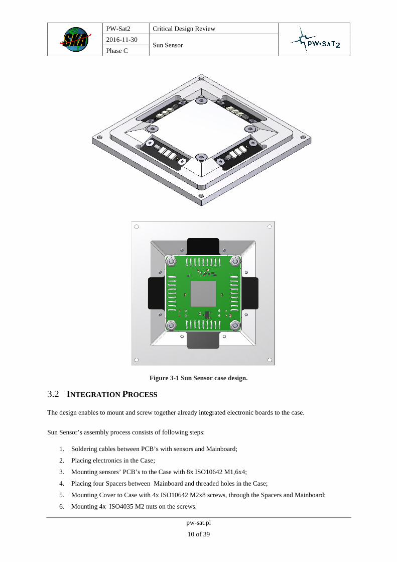
Figure 3-1 Sun Sensor case design.
3.2 INTEGRATION PROCESS
The design enables to mount and screw together already integrated electronic boards to the case.
Sun Sensor’s assembly process consists of following steps:
1. Soldering cables between PCB’s with sensors and Mainboard;
2. Placing electronics in the Case;
3. Mounting sensors’ PCB’s to the Case with 8x ISO10642 M1,6x4;
4. Placing four Spacers between Mainboard and threaded holes in the Case;
5. Mounting Cover to Case with 4x ISO10642 M2x8 screws, through the Spacers and Mainboard;
6. Mounting 4x ISO4035 M2 nuts on the screws.

PW-Sat2 Critical Design Review
2016-11-30 Sun Sensor
Phase C
pw-sat.pl
11 of 39
An additional document describing the process of integration will be provided. (TBD)
Figure 3-2 Sun Sensor case assembly

PW-Sat2 Critical Design Review
2016-11-30 Sun Sensor
Phase C
pw-sat.pl
12 of 39
4 ELECTRONICS DESIGN
4.1 CHANGES DESCRIPTION
Since Phase B, several changes were introduced in the design of electronic circuits in order to fulfil new
requirements (space limits, integration issues and problems with photovoltaic cells fabrication) - for more details
on this topic see chapter 2.2.
4.1.1 DIGITAL LIGHT INTENSITY SENSORS
The main change, affecting rest of the electronics of the Sun Sensor, is a new type of light intensity sensor. In a
previous models to sense intensity of light, photovoltaic cells (PV) were utilized. As a purely analog device, a PV
cell demands bias and readout circuits consisting of analog and analog-to-digital interfaces. In order to simplify
whole system and get rid of a huge part of analog, noise susceptible and space-consuming electronics, a new type
of sensor was selected. Digital ambient light sensor BH1730FVC from ROHM Semiconductor is a highly
integrated circuit. It consists of two photodiodes (for visible light and infrared), programmable gain amplifiers,
analog-to-digital converters and control logics. The sensor has digital, I2C interface, allowing easy and reliable
way of communication with any microcontroller unit.
Three digital sensors are placed on every of four, small PCBs resembling a photovoltaic panel used in earlier
models of the Sun Sensor.
Figure 4-1 Module (a small PCB) with three digital ALS replacing an analog photovoltaic panel.

PW-Sat2 Critical Design Review
2016-11-30 Sun Sensor
Phase C
pw-sat.pl
13 of 39
Figure 4-2 Panels with ALS sensors and RTD thermometers.
4.1.2 COMPACT MAIN BOARD
Thanks to changes introduced in light sensing elements, a number of parts that are necessary to be put on the main
board of the Sun Sensor was dramatically reduced. Now, light intensity data are acquired by the main board in
purely digital form, so the analog interface is no longer needed. Simplified and reduced analog part is present only
for temperature sensing. Thanks to these changes, the main board is as small as a 29 mm – edge square – see Figure
4-3.
Figure 4-3 Main, 4-layer printed circuit board with dimensions.
PW-Sat2 Critical Design Review
2016-11-30 Sun Sensor
Phase C
pw-sat.pl
14 of 39
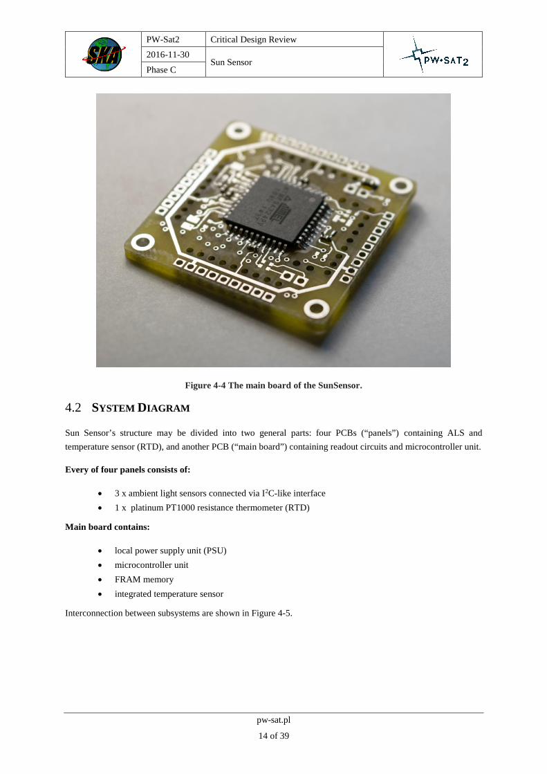
Figure 4-4 The main board of the SunSensor.
4.2 SYSTEM DIAGRAM
Sun Sensor’s structure may be divided into two general parts: four PCBs (“panels”) containing ALS and
temperature sensor (RTD), and another PCB (“main board”) containing readout circuits and microcontroller unit.
Every of four panels consists of:
3 x ambient light sensors connected via I2C-like interface
1 x platinum PT1000 resistance thermometer (RTD)
Main board contains:
local power supply unit (PSU)
microcontroller unit
FRAM memory
integrated temperature sensor
Interconnection between subsystems are shown in Figure 4-5.

PW-Sat2 Critical Design Review
2016-11-30 Sun Sensor
Phase C
pw-sat.pl
15 of 39
Figure 4-5 Sun Sensor architecture diagram.
Figure 4-6 Render of the Sun Sensor.

PW-Sat2 Critical Design Review
2016-11-30 Sun Sensor
Phase C
pw-sat.pl
16 of 39
4.3 DESCRIPTION OF OPERATION
4.3.1 LIGHT INTENSITY MEASUREMENT
Sun Sensor has three sets of four light sensors to measure intensity of incident light. To proper operation the Sun
Sensor needs only one set of light sensors. Other sets are used to average a measurement (to increase accuracy).
They can be also considered as redundant ones.
Figure 4-7 Light sensors grouped into three sets of four.
Digital ambient light sensor BH1730FVC from ROHM Semiconductor is able to measure visible light and infrared
by separate photodiodes and ADCs. Thanks to built-in PGA and selectable ADC integration time the sensor can
detect light in very wide range up to 65535 lx with resolution of 1 lx (16 bit). In some circumstances, resolution
might be increased by use of PGA, but then range of the sensor is affected. Output decimal code is linearly
proportional to the light intensity. Communication with sensor take place via I2C bus. Each sensor has the same
slave address. Internal architecture of BH1730FVC is shown in Figure 4-8, whereas Table 4-1 summarizes the
most important parameters of the light sensor.
The sensor has two 16-bit registers storing last result of conversion, one for visible light and IR. Conversion start
may be configured in free-running mode or triggered by a command transferred via I2C.

PW-Sat2 Critical Design Review
2016-11-30 Sun Sensor
Phase C
pw-sat.pl
17 of 39
Figure 4-8 BH1730FVC ALS internal architecture.
Table 4-1 BH1730FVC sensor specification.
No Parameter Value Units
1 Supply voltage 2.4 - 3.6 V
2 Supply power 0.6 mW
3 Measurement range 0.008 - 65535 lx
4 Integration time 2.7 - 688.5 ms
5 Communication interface I2C, one slave address -
6 Dimensions 3.0 x 1.6 x 0.75 mm
Simultaneous light intensity measurements
To work properly, Sun Sensor needs light intensity data from all sensors in a set measured at the same time. When
satellite is in non-stationary state (it has some angular velocity), time shift between measurements introduces an
error in final output. To minimize this negative effect, conversion is triggered in all sensors exactly at the time. In
order to do this, all four sensors in a set are connected in a special way.
All SCL lines are tied together, thus the clock is common for whole set of sensors. However, data lines (SDA) are
connected to MCU independently - see Figure 4-9.

PW-Sat2 Critical Design Review
2016-11-30 Sun Sensor
Phase C
pw-sat.pl
18 of 39
Figure 4-9 Connection of four sensors to microcontroller (one ‘set’).
An I2C interface is emulated using MCU’s GPIOs (bit banging). Bytes are read and written to the sensor by
following manner:
Write byte:
1. generate start bit (according to I2C specification standard)
2. set proper states at SDA lines according to i-th bit
3. generate clock pulse
4. jump to 2. if there are bits left in a byte
5. generate stop bit (according to I2C specification standard)
Read byte:
1. generate start bit (according to I2C specification standard)
2. set all SDA GPIOs as input
3. acquire state of each SDA line
4. generate clock pulse
5. jump to 3. if there are left bits in a byte
6. generate stop bit (according to I2C specification standard)
Typical scenario of data acquisition from 12 sensors:
write proper bytes to settings registers of all 12 light sensors
write byte triggering light conversion (at the same time to set of four sensors), then do the same for
next group of 4 sensor, and finally for the last set of four sensors
when conversion is completed, read data registers from the first group of four sensors, then for second
and finally third groups.
Because each set of sensors is driven by separate clock, it’s not possible to trigger conversion for all groups at
once, but with properly written driver for AVR microcontroller the delay is negligible.

PW-Sat2 Critical Design Review
2016-11-30 Sun Sensor
Phase C
pw-sat.pl
19 of 39
Measurement reliability and redundancy
In order to provide a high level of reliability of angle measurement and immunity to failures, redundant ALS
sensors are present in the Sun Sensor.
Ambient Light Sensors are one of the most intensively exposed to cosmic radiation electronic parts of the entire
satellite. They have to operate in a wider temperature range than e.g. electronics on main board of the Sun Sensor.
Because of that, triple-mode redundancy of ALS sensors was implemented in the Sun Sensor.
Each set consisting of 4 sensors can deliver full data needed for angle determination. Taking measurement by three
sets of sensors with a very short time gap between them, then using voting algorithm allow to detect sensors
malfunctions. In the worst case, with proper calibration and software, Sun Sensor should work (i.e. return proper
angle with respect to the Sun) even if case of failure of one light sensor in each group (A-D) - see Figure 4-10.
Figure 4-10 Groups of redundant ambient light sensors.
Temperature influence on BH1730FVC light measurement
As mentioned in previous chapters, the ALS light sensors exhibit non-zero temperature dependence on both visible
and infrared light measurements. In order to compensate response of the sensors a calibration curves were
measured.
Two sensors placed close to each other were lit with a constant intensity, white light from a halogen lamp powered
by a DC voltage source. Temperature of the device was changed in range starting from 30 up to 100 °C. Obtained
characteristics are shown in Figure 4-11 and Figure 4-12.

PW-Sat2 Critical Design Review
2016-11-30 Sun Sensor
Phase C
pw-sat.pl
20 of 39
20 30 40 50 60 70 80 90 100 110
560
580
600
620
640
660
680
700
720illuminated by a constant-intensity
light source
BH1730 digital light sensorL
igh
t in
ten
sity (
AD
C C
oun
t)
Temperature (Celsius degree)
VL - sensor 1
VL - sensor 2
Figure 4-11 Calibration characteristic for visible light photodiode in the ALS.
20 30 40 50 60 70 80 90 100 110
460
480
500
520
540
560illuminated by a constant-intensity
light source
BH1730 digital light sensor
Lig
ht in
tensity (
AD
C C
ount)
Temperature (Celsius degree)
IR - sensor 1
IR - sensor 2
Figure 4-12 Calibration characteristic for infrared photodiode in the ALS.

PW-Sat2 Critical Design Review
2016-11-30 Sun Sensor
Phase C
pw-sat.pl
21 of 39
4.3.2 TEMPERATURE MEASUREMENT
There are five thermometers in the Sun Sensor, but only four of them, RTDs mounted on panels close to the light
sensors have significant relevance for measurement correctness and accuracy. The fifth sensor (analog integrated
circuit, LM60) is mounted on the main board and its intention is measurement of general temperature of the Sun
Sensor. Nonetheless if temperature is kept within the operating range of electronic components, its indication has
little or no effect on the Sun Sensor measurements, thus its accuracy is not critical.
4.3.2.1 Platinum Resistive Temperature Sensors - PT1000
Requirements
- measurement range: -55 ºC - 150 ºC
- resolution: at least 1 ºC
- channels: 4
- sample rate: at least 1 Sps
The resistance of PT1000 RTD in given interval of the temperatures varies from 783.19 Ω up to 1573.1 Ω.
Temperature dependence on resistance is described by IEC751 / ITS-90 standards.
Figure 4-13 PT1000 RTD platinum sensor in SMD 0805 package.
In order to convert resistance changes of RTDs to a voltage, a simple circuit of voltage divider was implemented.
Then, the output voltage passes through passive low-pass filter cutting all high frequency noise components.
Filtered signal is sampled by built-in AVR microcontroller 10-bit analog-to-digital converter. Thanks to
oversampling technique, a resolution of measurement is increased to 12 bit. Block diagram of RTD interface is
presented in Figure 4-14, while schematic implementation is shown in Figure 4-15. In turn, Figure 4-16 shows a
theoretical simulation of RTD resolution vs. temperature. Results show that resolution better than 1 ºC is
achievable over the whole range.

PW-Sat2 Critical Design Review
2016-11-30 Sun Sensor
Phase C
pw-sat.pl
22 of 39
Figure 4-14 RTD platinum sensor readout circuit architecture.
Figure 4-15 Analog interface for RTDs.

PW-Sat2 Critical Design Review
2016-11-30 Sun Sensor
Phase C
pw-sat.pl
23 of 39
Figure 4-16 Resolution of temperature measurement with PT1000 RTDs.
4.3.2.2 Main board temperature sensor - LM60
The analog output of integrated temperature sensor LM60 placed on the main board is proportional to the actual
temperature. The characteristic of the sensor is described in the manufacturer’s datasheet. Output of the sensor
passes through a passive low-pass filter and then it is connected to internal AVR’s analog-to-digital converter. A
10-bit ADC with 2.048 V results in 0.3125 ºC/LSB. This result may be improved by oversampling.
4.3.3 MICROCONTROLLER UNIT
Microcontroller tasks in the SunSensor are:
- taking measurements (ALS data exchange, temperatures with built-in ADC, telemetry),
- angle calculations,
- communication with OBC.
Due to chosen ADC the microcontroller must have following interfaces:
- I2C bus – satellite bus,
- Sufficient number of GPIOs – to connect ALS sensors
- Sufficient number of ADC channels – to connect 5 analog thermometers
- ISP/JTAG for first-time bootloader burning,
- UART for programming and debugging in development phase.
As a microcontroller that fulfils all mentioned needs AVR MCU from Atmel - ATmega324P-15AT1 was chosen.

PW-Sat2 Critical Design Review
2016-11-30 Sun Sensor
Phase C
pw-sat.pl
24 of 39
4.3.4 FRAM MEMORY
Ferromagnetic Random Access Memory (FRAM) is optional and may be used to store calibration coefficients for
the sensor.

PW-Sat2 Critical Design Review
2016-11-30 Sun Sensor
Phase C
pw-sat.pl
25 of 39
5 SENSOR COMPUTING ALGORITHM
The algorithm working on the sensor will use the signals gathered from the ALS sensors and calculate the Sun
Vector value, based on the model of the half sphere expected measurements.
5.1 GENERAL ASSUMPTIONS
First and most critical assumption for light sensor is to have algorithm which will run relatively fast. Next thing is
limitation of memory, so the algorithm must work fast and be efficient in term of memory usage.
5.2 DESCRIPTION
Algorithm designed for light sensor is based on Neural Network. Neural network developed for this task got
structure shown on Figure 5-1. Network got two hidden layers, this structure helps with approximation of highly
nonlinear function of dependent signals from sensors.
Figure 5-1: Structure of neural network used for approximation.
5.2.1 DEPENDENT SIGNALS
In process of designing algorithms there was a need for become independent from change of amplitude of signal.
Shift of amplitude can occur due to various factors , and we are not able to determine signals level on the orbit,
but we can determine correlation between them. Let’s assume we got four signals I1,I2,I3,I4 from four sensor’s
sides. In satellite coordinate frame, in comparison to the Figure 4-3, I1 is on the A side, I2 is on the D side, I3 – C
side and I4 – B side. With such order defined we can define Relative signals R1 and R2 which are as defined
below:
R1 = (I1-I3)/(I1+I3)
R2 = (I2-I4)/(I2+I4)

PW-Sat2 Critical Design Review
2016-11-30 Sun Sensor
Phase C
pw-sat.pl
26 of 39
Figure 5-2: presentation of R1 in polar coordinates.
Signal R1 is dependent on orientation of the Sun relative to sensor. In the Figure 5-2 we can see signal in polar
coordinates (where radius is 90° – elevation of sun, and angle is rotation of sun relative to satellite coordinate
system ). Signal R2 differs from R1 only by 90° rotation.
5.2.2 TRAINING NETWORK
Because signals R1 and R2 are symmetric, network can operate on first quarter of the circle. ( Elevation from 20
to 90° and rotation from 0 to 90°). For other 270° of rotation first signal must be brought to first quarter of a circle
(change signal sign to be positive and remember its original form to rotate outputs from network). Training of the
network is performed on the extended set of data. This set is defined from -10 to 100° in rotation axis and from 20
to 90° in elevation axis (points in this set are located every 1° in both axis). This approach gives two advantages.
Firstly, function is continuous on 0 and 90° rotation. Secondly, if noise is added (for example when measurement
is made) it can suggest that rotation is smaller than 0 or bigger than 90°.
Training neural network is done with MATLAB toolbox tools. Training algorithm which is used is named
Levenberg-Marquardt.

PW-Sat2 Critical Design Review
2016-11-30 Sun Sensor
Phase C
pw-sat.pl
27 of 39
5.2.3 EXPORT CODE
After saving neural network as MATLAB function it is exported by internal exporter to c code.
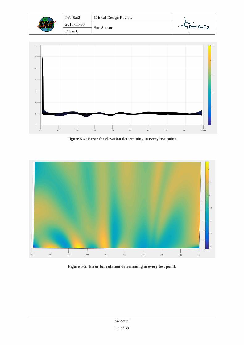
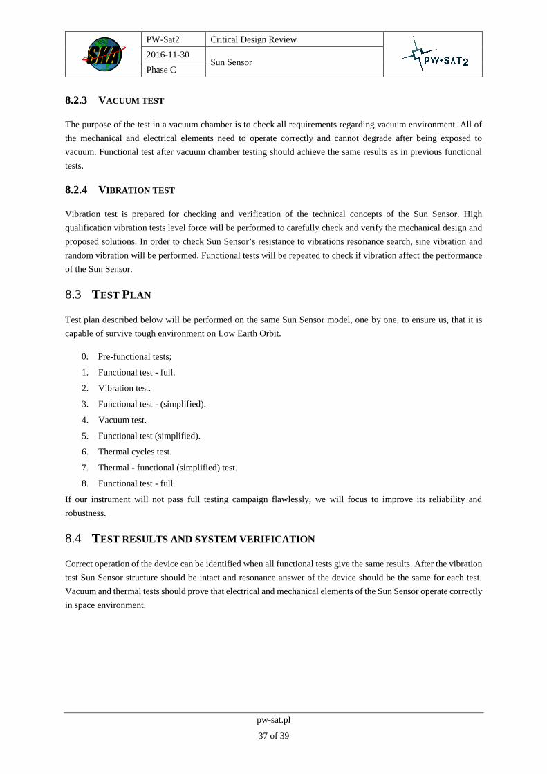
5.3 THEORETICAL RESULTS
Testing data set was set from 0 to 90° in rotation axis and 20 to 90° in sun elevation. This dataset is denser than
Training set (points are located every 0.1° in both axis).
Values visualized on figures 5-3 and 5-4 are an error of elevation measured as difference between elevation from
network output and this in test point. Error of this approximation is about from 1.3° to -2.1° in elevation axis and
from 1.9° to -2.23° in rotation axis everywhere but on 90° rotation. In this case function (R1, R2->rot, elev) is
non-injective and this error cannot be eliminated. On figures 5-5 and 5-6 there is presented error of rotation. Again
values of this error are low everywhere but for 90° rotation. Tests showed that this algorithm is executed in less
than 10ms on Arduino Uno (which has almost identical microcontroller like the one in used in the sensor).
Figure 5-3: Error for elevation determining in every test point.
PW-Sat2 Critical Design Review
2016-11-30 Sun Sensor
Phase C
pw-sat.pl
28 of 39
Figure 5-4: Error for elevation determining in every test point.
Figure 5-5: Error for rotation determining in every test point.

PW-Sat2 Critical Design Review
2016-11-30 Sun Sensor
Phase C
pw-sat.pl
29 of 39
Figure 5-6: Error for rotation determining in every test point.

PW-Sat2 Critical Design Review
2016-11-30 Sun Sensor
Phase C
pw-sat.pl
30 of 39
6 MCU EMBEDDED SOFTWARE
This section describes software that runs on Sun Sensor’s AVR microcontroller.
6.1 GENERAL DESCRIPTION
A software for the SunSensor’s AVR microcontroller is written in C++ programming language utilizing AVR-
HAL library developed by the PW-Sat2 Team, that provides hardware abstraction layer. The library is used in
order to speed-up development process and improve its reliability. The AVR-HAL library is responsible for low-
level functions of the MCU and was tested separately to the whole SunSensor application in automated, hardware-
in-the-loop tests.
6.2 COMMUNICATIONS VIA I2C
The SunSensor communicates with a master device by an I2C bus. Standard communication procedure is described
below:
1. Set trigger bit in Control and Status register (see Table 6-1) to request a new measurement.
2. Check Control and Status register for “new data” flag. The flag is usually set within 100 ms after new
data request.
3. If the flag “new data” is set, data registers (0x01 – 0x2F) are up to date. Now it is possible to read registers
with data that are demanded.
Several registers can be read in one I2C transaction. The register pointer within the SunSensor increments to
the next address always after reading a byte.
6.3 COMMANDS AND REGISTERS
Table 6-1 Register map of the SunS
Address Name Description Data type Type Physical
interpretation
0x00 Control and
Status
bit 0: error state
bit 1: trigger
bit 2: new data
bit field
8 bit RW -
0x01 Azimuth angle uint16_t R degrees
0x03 Elevation angle uint16_t R degrees
0x05 Temperature A int16_t R Centigrades
0x07 Temperature B int16_t R Centigrades
0x09 Temperature C int16_t R Centigrades
0x0B Temperature D int16_t R Centigrades

PW-Sat2 Critical Design Review
2016-11-30 Sun Sensor
Phase C
pw-sat.pl
31 of 39
Address Name Description Data type Type Physical
interpretation
0x0D Temperature
structure int16_t R Centigrades
0x0F ALS 1A RAW uint16_t R raw
0x11 ALS 1B RAW uint16_t R raw
0x13 ALS 1C RAW uint16_t R raw
0X15 ALS 1D RAW uint16_t R raw
0x17 ALS 2A RAW uint16_t R raw
0x19 ALS 2B RAW uint16_t R raw
0x1B ALS 2C RAW uint16_t R raw
0x1D ALS 2D RAW uint16_t R raw
0x1F ALS 3A RAW uint16_t R raw
0x21 ALS 3B RAW uint16_t R raw
0x23 ALS 3C RAW uint16_t R raw
0x25 ALS 3D RAW uint16_t R raw
0x27 Temperature A uint16_t R raw
0x29 Temperature B uint16_t R raw
0x2B Temperature C uint16_t R raw
0x2D Temperature D uint16_t R raw
0x2F Temperature
structure uint16_t R raw

PW-Sat2 Critical Design Review
2016-11-30 Sun Sensor
Phase C
pw-sat.pl
32 of 39
7 SUN SENSOR PROTOTYPE
A Sun Sensor prototype in the metal case is to be built during writing of this documentation. First integration of
the electronics with the aluminum case structure will verify the integration process and accuracy of the alignment
of the sensors. Earlier testing with 3d printed parts gave basic information about predicted performance (see fig.
Figure 7-1). The prototype model will be used to gather the measurements from the sensors for the whole field of
view of the sensor and compared with the theoretical predictions. Based on this measurements, there will be
prepared the final version of the angles processing algorithm. Then the prototype will be tested in the functional
tests.
Figure 7-1 A picture of the SunSensor prototype during assembly.

PW-Sat2 Critical Design Review
2016-11-30 Sun Sensor
Phase C
pw-sat.pl
33 of 39
Figure 7-2 A picture of the SunSensor prototype during assembly.

PW-Sat2 Critical Design Review
2016-11-30 Sun Sensor
Phase C
pw-sat.pl
34 of 39
8 TESTING
To ensure that the instrument can work properly in low Earth orbit, there must be carried out a test campaign. In
this chapter there is presented the idea for the final functional and qualification tests.
8.1 TEST STAND
Sun Sensor Test Stand is a system used for the performance tests. It consists of:
light source: metal - halide lamp mounted on reflector or halogen;
diaphragm: it allows only collimated beam reach Sun Sensor;
rotating table: with two stepper motors, it provides rotation of the Sun Sensor within two axis.
8.1.1 LIGHT SOURCE
For light source there have been chosen two solutions: halogen and metal halide lamp. Both lamps has different
light characteristics. Halogen lamp is an incandescent light source with less light power and is used without any
additional system. Second lamp is a discharge lamp, prepared in another project in the SKA, named Słonecznik.
It has collimated light, but because of the passive electric ballast, there are oscillations in the lighting. This lamp
gives very good approximation of the Sun spectrum expected on the orbit.
In the Słonecznik, PHILIPS MSR1200 lamp (model 245514) has been chosen. Lamp characteristics and spectral
range are presented below.
Table 8-1 Philips MSR 1200 1CT characteristics
Light Technical Characteristics
Color Rendering Index 80 Ra8
Color Temperature 5900 K
Color Temperature Technical 5900 K
Chromaticity Coordinate X 325 -
Chromaticity Coordinate Y 320 -
Luminous Flux Lamp EM 94000 (min), 110000 (nom) Lm
Luminous Effiacy Lamp EM 91 Lm/W
Electrical Characteristics
Watts 1200 W
Lamp Wattage Technical 1200 W

PW-Sat2 Critical Design Review
2016-11-30 Sun Sensor
Phase C
pw-sat.pl
35 of 39
Lamp Current 13.8 A
Ignition Supply Voltage 207 (min) V
Dimmable No
Figure 8-1 Philips MSR lamp spectral range
Reflector used in the test stand is aluminum parabolic Edmund Optics with a diameter of 300 mm. The focal length
of the reflector is 75 mm. The thickness of the aluminum is 1 mm. The reflector is surrounded by a reinforcement
ring in addition to which the overall diameter is 308 mm. The reflective surface is polished aluminum which
reflects radiation over a wide frequency range.
8.1.2 ROTATING TABLE
Rotating table construction consists of two stepper motors and gives the ability to rotate on two axes. It enables to
measure accuracy of Sun Sensor in half-sphere space. Test stand configuration is presented below. Stepper motors
gives the control accuracy less than 0.1°. After the Test Stand calibration there is possible to know precisely the
angular position of the mounted Sun Sensor from the positions of the motors.
Figure 8-2 Test Stand configuration

PW-Sat2 Critical Design Review
2016-11-30 Sun Sensor
Phase C
pw-sat.pl
36 of 39
8.2 REQUIRED TESTS DESCRIPTION
8.2.1 FUNCTIONAL TESTS
The foundations of testing campaign are functional tests, which are the verification of the Sun Sensor’s system
performance, proper alignment and accuracy. For the accuracy testing, the Rotary Table is used to achieve all the
angles from the field of view of the Sun Sensor with proper sampling. The signals gathered from the ALS sensors
are used for the angular characteristics verification, noise verification, then used as an input for the neural network
and angles calculations.
Because of the time required for the full test, it was proposed to introduce simplified functional test, which is faster
full test, with different angles sampling in full field of view.
The functional tests require:
4. Dark room;
5. SunS Test Stand;
6. SunSensor;
7. PC;
8. Payload Board;
9. OBC evaluation module.
8.2.1.1 Full functional test
The functional tests should be performed for as much position angles as possible. To measure accuracy of Sun
Sensor, it will be positioned in half-sphere angles using test stand described in chapter 8.1. The positioning
accuracy will be checked for every 0.5°. All of the data will give two dimensional characteristics of signals from
the ALS sensors. There will be checked differences between the sensors readouts as well as the algorithm
performance. The Rotary Table will achieve the azimuth angle 0°-360° and the elevation angle 20°-90°. The results
will be compared with the same results for the reference sun sensor, NSS Cubesat Sun Sensor, used for the ADCS
system, which has the accuracy <0.5° after its calibration.
8.2.1.2 Simplified functional test
Performing full functional test will need a lot of time because of achieving every assumed angle. Thus the full test
will be performed less times, to do more rough test, with sampling of 1°-5°(TBD), with a few denser regions, with
sampling 0.5°, where the angular calculations can sensitive. The size of the regions will be 5°x5°(TBD).
8.2.2 THERMAL TEST
The temperature cycle shall verify operational performance of the unit exposed to lower and upper temperature in
the thermal chamber. The Sun Sensor must operate correctly at all operating conditions and it will be subjected to
the minimum and maximum non - operating temperatures to verify that no degradation occurs. After several cycles
of temperature change, simplified functional test of the Sun Sensor inside the thermal chamber will be performed
and the simple light source will be used, because of the chamber limitations.
PW-Sat2 Critical Design Review
2016-11-30 Sun Sensor
Phase C
pw-sat.pl
37 of 39
8.2.3 VACUUM TEST
The purpose of the test in a vacuum chamber is to check all requirements regarding vacuum environment. All of
the mechanical and electrical elements need to operate correctly and cannot degrade after being exposed to
vacuum. Functional test after vacuum chamber testing should achieve the same results as in previous functional
tests.
8.2.4 VIBRATION TEST
Vibration test is prepared for checking and verification of the technical concepts of the Sun Sensor. High
qualification vibration tests level force will be performed to carefully check and verify the mechanical design and
proposed solutions. In order to check Sun Sensor’s resistance to vibrations resonance search, sine vibration and
random vibration will be performed. Functional tests will be repeated to check if vibration affect the performance
of the Sun Sensor.
8.3 TEST PLAN
Test plan described below will be performed on the same Sun Sensor model, one by one, to ensure us, that it is
capable of survive tough environment on Low Earth Orbit.
0. Pre-functional tests;
1. Functional test - full.
2. Vibration test.
3. Functional test - (simplified).
4. Vacuum test.
5. Functional test (simplified).
6. Thermal cycles test.
7. Thermal - functional (simplified) test.
8. Functional test - full.
If our instrument will not pass full testing campaign flawlessly, we will focus to improve its reliability and
robustness.
8.4 TEST RESULTS AND SYSTEM VERIFICATION
Correct operation of the device can be identified when all functional tests give the same results. After the vibration
test Sun Sensor structure should be intact and resonance answer of the device should be the same for each test.
Vacuum and thermal tests should prove that electrical and mechanical elements of the Sun Sensor operate correctly
in space environment.

PW-Sat2 Critical Design Review
2016-11-30 Sun Sensor
Phase C
pw-sat.pl
38 of 39
9 ON ORBIT OPERATION
Because the Sun Sensor is an experimental device, it is not part of the satellite’s bus and is not used by the ADCS
subsystem. The main satellite’s sun sensor (named NSS CubeSat Sun Sensor) )is placed on the same wall of the
satellite and is required for the spin Sun Pointing mode. This sensor will be the reference for the designed Sun
Sensor. The Sun Sensor experiments will be conducted during the experiments phase.
9.1 OPERATING PLAN
The Sun Sensor will operate in a few modes: a single Sun’s Vector reading and constant work with determined
frequency.
1. Single SunS position reading - the OBC asks to get the single measurement. The readings of the Sun’s
Vector can be send in raw format (as a current readings from ALS sensors and thermometers) or processed
format (angles and temperatures). The OBC can access all data at the time or just one register.
2. Constant operation - In the constant operating mode the chosen data will be send to the OBC with the
frequency of the ADCS algorithm operation or any other determined. The OBC will use the looped
command as for the single position reading mode. The constant operation mode sessions will last for the
time determined by the telecommand (TBD).
At the same time of the SunS readings, the OBC will gather the same data from the reference sensor. The data will
be saved as angle measurement and difference between the sensors measurements or the raw data, with a timestamp
for every data package.
The Sun Sensor experiment will be conducted by the ground control. Satellite operation do not assume the
additional attitude path control, thus the Sun Sensor performance will be checked during the sessions determined
by the telecommands. The Sun Sensor will be turned on during the experiments phase. There is assumed the Sun
Sensor will be turned on for 10-30 mins, starting from the telecommand reception or the time determined by the
telecommand. Experiment will be ordered at least one time per communication session during the experiments
phase of the Sun Sensor. During the next ground session the data will to be sent to the ground station. In case of
good health of the satellite and good communication, the Sun Sensor will be turned on for full 2-3 days of the
experiments phase of the Sun Sensor. Additionally the Detumbling or Sun Pointing ADCS modes may be used.
9.2 REQUIRED DATA AND DATA RATE
Sun Sensor will gather the raw data of currents on the ALS sensors and thermometers. Based on them it will
calculate angular position data. All of the data can be acquired by the OBC. Sun Sensor will operate in a single
mode i.e. acquisition must be triggered by the OBC each time.
In the most demanding case of acquiring the raw Sun Sensor data with a sampling 1/s, from all 12 ALS sensors
and 5 values from the thermometers for the time of 10 minutes, there will be required about 20kB of free memory
on board. The more typical cases assumes 10s sampling for 30 minutes of SunS calculated readings with
temperatures and reference sensor readings and requires about 4kB. (TBD)

PW-Sat2 Critical Design Review
2016-11-30 Sun Sensor
Phase C
pw-sat.pl
39 of 39
9.3 ON ORBIT SYSTEM VERIFICATION DESCRIPTION
Below there is presented exemplary procedure of the Sun Sensor experimental measurement (TBD):
command from the ground: [duration of the acquisition] [sample rate];
ADCS turns off Detumbling;
acquisition of data from experimental Sun Sensor, reference Sun Sensor and gyros to some space in
memory;
end of the experiment after given time;
command from the ground to download data from last experiment.