Sun Fire™ E2900 Systems_datasheet
76
Sun Microsystems, Inc. www.sun.com Submit comments about this document at: http://www.sun.com/hwdocs/feedback Sun Fire ™ E2900 Systems Installation Guide Part No. 817-4053-15 May 2006, Revision A
description
Sun Fire E2900
Transcript of Sun Fire™ E2900 Systems_datasheet

Sun Microsystems, Inc.www.sun.com
Submit comments about this document at: http://www.sun.com/hwdocs/feedback
Sun Fire™ E2900 SystemsInstallation Guide
Part No. 817-4053-15May 2006, Revision A

PleaseRecycle
Copyright 2006 Sun Microsystems, Inc., 4150 Network Circle, Santa Clara, California 95054, U.S.A. All rights reserved.
Sun Microsystems, Inc. has intellectual property rights relating to technology that is described in this document. In particular, and withoutlimitation, these intellectual property rights may include one or more of the U.S. patents listed at http://www.sun.com/patents and one ormore additional patents or pending patent applications in the U.S. and in other countries.
This document and the product to which it pertains are distributed under licenses restricting their use, copying, distribution, anddecompilation. No part of the product or of this document may be reproduced in any form by any means without prior written authorization ofSun and its licensors, if any.
Third-party software, including font technology, is copyrighted and licensed from Sun suppliers.
Parts of the product may be derived from Berkeley BSD systems, licensed from the University of California. UNIX is a registered trademark inthe U.S. and in other countries, exclusively licensed through X/Open Company, Ltd.
Sun, Sun Microsystems, the Sun logo, AnswerBook2, docs.sun.com, Sun Fire, Sun StorEdge, Netra, and Solaris are trademarks or registeredtrademarks of Sun Microsystems, Inc. in the U.S. and in other countries.
All SPARC trademarks are used under license and are trademarks or registered trademarks of SPARC International, Inc. in the U.S. and in othercountries. Products bearing SPARC trademarks are based upon an architecture developed by Sun Microsystems, Inc.
The OPEN LOOK and Sun™ Graphical User Interface was developed by Sun Microsystems, Inc. for its users and licensees. Sun acknowledgesthe pioneering efforts of Xerox in researching and developing the concept of visual or graphical user interfaces for the computer industry. Sunholds a non-exclusive license from Xerox to the Xerox Graphical User Interface, which license also covers Sun’s licensees who implement OPENLOOK GUIs and otherwise comply with Sun’s written license agreements.
U.S. Government Rights—Commercial use. Government users are subject to the Sun Microsystems, Inc. standard license agreement andapplicable provisions of the FAR and its supplements.
DOCUMENTATION IS PROVIDED "AS IS" AND ALL EXPRESS OR IMPLIED CONDITIONS, REPRESENTATIONS AND WARRANTIES,INCLUDING ANY IMPLIED WARRANTY OF MERCHANTABILITY, FITNESS FOR A PARTICULAR PURPOSE OR NON-INFRINGEMENT,ARE DISCLAIMED, EXCEPT TO THE EXTENT THAT SUCH DISCLAIMERS ARE HELD TO BE LEGALLY INVALID.
Copyright 2006 Sun Microsystems, Inc., 4150 Network Circle, Santa Clara, Californie 95054, Etats-Unis. Tous droits réservés.
Sun Microsystems, Inc. a les droits de propriété intellectuels relatants à la technologie qui est décrit dans ce document. En particulier, et sans lalimitation, ces droits de propriété intellectuels peuvent inclure un ou plus des brevets américains énumérés à http://www.sun.com/patents etun ou les brevets plus supplémentaires ou les applications de brevet en attente dans les Etats-Unis et dans les autres pays.
Ce produit ou document est protégé par un copyright et distribué avec des licences qui en restreignent l’utilisation, la copie, la distribution, et ladécompilation. Aucune partie de ce produit ou document ne peut être reproduite sous aucune forme, par quelque moyen que ce soit, sansl’autorisation préalable et écrite de Sun et de ses bailleurs de licence, s’il y en a.
Le logiciel détenu par des tiers, et qui comprend la technologie relative aux polices de caractères, est protégé par un copyright et licencié par desfournisseurs de Sun.
Des parties de ce produit pourront être dérivées des systèmes Berkeley BSD licenciés par l’Université de Californie. UNIX est une marquedéposée aux Etats-Unis et dans d’autres pays et licenciée exclusivement par X/Open Company, Ltd.
Sun, Sun Microsystems, le logo Sun, AnswerBook2, docs.sun.com, Sun Fire, Sun StorEdge, Netra, et Solaris sont des marques de fabrique ou desmarques déposées de Sun Microsystems, Inc. aux Etats-Unis et dans d’autres pays.
Toutes les marques SPARC sont utilisées sous licence et sont des marques de fabrique ou des marques déposées de SPARC International, Inc.aux Etats-Unis et dans d’autres pays. Les produits portant les marques SPARC sont basés sur une architecture développée par SunMicrosystems, Inc.
L’interface d’utilisation graphique OPEN LOOK et Sun™ a été développée par Sun Microsystems, Inc. pour ses utilisateurs et licenciés. Sunreconnaît les efforts de pionniers de Xerox pour la recherche et le développement du concept des interfaces d’utilisation visuelle ou graphiquepour l’industrie de l’informatique. Sun détient une license non exclusive de Xerox sur l’interface d’utilisation graphique Xerox, cette licencecouvrant également les licenciées de Sun qui mettent en place l’interface d ’utilisation graphique OPEN LOOK et qui en outre se conformentaux licences écrites de Sun.
LA DOCUMENTATION EST FOURNIE "EN L’ÉTAT" ET TOUTES AUTRES CONDITIONS, DECLARATIONS ET GARANTIES EXPRESSESOU TACITES SONT FORMELLEMENT EXCLUES, DANS LA MESURE AUTORISEE PAR LA LOI APPLICABLE, Y COMPRIS NOTAMMENTTOUTE GARANTIE IMPLICITE RELATIVE A LA QUALITE MARCHANDE, A L’APTITUDE A UNE UTILISATION PARTICULIERE OU AL’ABSENCE DE CONTREFAÇON.
Contents
Regulatory Compliance Statements xi
Safety Agency Compliance Statements xv
Preface xxvii
1. Physical Installation 1–1
1.1 Installing Slides and Rails 1–2
1.1.1 Adjusting the Rail Assembly 1–3
1.1.2 Installing the Inner Slides on the System 1–4
1.1.3 Preparing the Rails for Two-Post Installations 1–6
1.1.4 Installing the Rail Assemblies in a Sun Fire/StorEdge Cabinet 1–7
1.1.4.1 Installing the Rail Assemblies in the Bottom Position1–7
1.1.4.2 Installing the Rail Assemblies in the Top Position 1–8
1.1.5 Installing the Rail Assemblies in a Sun Rack 900 Cabinet 1–9
1.1.5.1 Installing the Rail Assemblies in the Bottom Position1–9
1.1.5.2 Installing the Rail Assemblies in the Top Position 1–10
1.1.6 Installing the Rail Assemblies in a 19-Inch Four-Post Cabinet 1–11
1.1.7 Installing the Rail Assemblies in a 19-inch Two-Post Rack 1–12
1.2 Installing the System in a Cabinet 1–13
iii

1.2.1 Preparing to Install the System in the Cabinet 1–13
1.2.2 Mounting the System in the Cabinet 1–15
1.3 Installing Slide Rail Locking Nuts 1–19
1.4 Installing the Cable Management Arm 1–21
1.4.1 Installing the CMA–Lite 1–22
1.4.2 Installing the CMA–800. 1–23
1.5 Connecting Sun Fire V1280/Netra 1280 Power Cables 1–30
1.6 Connecting Consoles to the System Controller 1–32
1.6.1 Connecting the Initial Administrative Console 1–33
1.6.2 Connecting the Administrative Console 1–35
1.7 Connecting the I/O Assemblies 1–35
1.8 Powering On the System 1–35
1.9 Powering Off the System 1–36
1.10 Installing Additional Hardware 1–36
1.11 Installing Additional Peripheral Devices 1–37
A. External Connections A–1
A.1 I/O Slots A–2
A.1.1 PCI IB_SSC Assemblies A–2
A.1.2 PCI+ IB_SSC Assemblies A–2
A.1.3 PCI-X IB_SSC Assemblies A–2
A.2 SCSI Connector A–3
A.2.1 SCSI Implementation A–4
A.3 Alarms Port A–5
A.4 LOM Serial Ports A–6
A.4.1 Using a DB-25 Adapter for Your Serial Link A–7
A.4.2 Using a DB-9 Adapter for Your Serial Link A–8
A.4.2.1 Connecting to a Male 9-Pin D-Type Serial Port A–8
A.5 10/100 LOM Ethernet Port A–9
iv Sun Fire E2900 Systems Installation Guide • May 2006

A.5.1 Twisted-Pair Ethernet Cable-Type Connectivity A–9
A.6 Net0/Net1 Ethernet Ports A–10
Contents v

vi Sun Fire E2900 Systems Installation Guide • May 2006

Figures
FIGURE 1-1 Rail Assembly (Standard Configuration) 1–3
FIGURE 1-2 Spring Clips and Cutouts 1–5
FIGURE 1-3 Rail Assembly (Modified for Two-Post Installation) 1–6
FIGURE 1-4 Installing the Rails in a Sun Fire Cabinet 1–8
FIGURE 1-5 Installing the Rails in a Sun Rack 900 Cabinet or 19-Inch Four-Post Cabinet 1–10
FIGURE 1-6 Releasing the Door Hinge Mechanism 1–13
FIGURE 1-7 Removing the Shipping Cradle Bolts 1–14
FIGURE 1-8 Inserting the Lifting Device into the Shipping Cradle 1–15
FIGURE 1-9 Aligning the Slides 1–16
FIGURE 1-10 Removing the Shipping Cradle 1–17
FIGURE 1-11 Pushing the System into the System Cabinet 1–18
FIGURE 1-12 Tightening the Securing Screws 1–18
FIGURE 1-13 Inserting and Tightening the Slide Rail Spacers 1–20
FIGURE 1-14 Inserting and Tightening the Slide Rail Locking Nut 1–20
FIGURE 1-15 Bracket Mounting Holes 1–21
FIGURE 1-16 CMA–Lite Cable Management Arm 1–22
FIGURE 1-17 Upper/Lower CMA Arms and Left Hand/Right Hand T-Brackets 1–23
FIGURE 1-18 Upper/Lower Pivot Bracket Mounting Holes 1–24
FIGURE 1-19 Attachment of Upper CMA Arm and Pivot Bracket 1–25
FIGURE 1-20 Attachment of Lower CMA Arm and Pivot Bracket 1–26
vii
FIGURE 1-21 Attaching Left Hand T-Bracket 1–27
FIGURE 1-22 Attachment of Right-Hand T-Bracket 1–28
FIGURE 1-23 Attachment of Upper/Lower CMA Arms to T-Bracket 1–29
FIGURE 1-24 System Controller and I/O Assembly Locations 1–34
FIGURE A-1 External I/O Connections—Sun Fire V1280/Netra 1280 Systems (Rear View) A–1
FIGURE A-2 68-Pin SCSI Connector A–3
FIGURE A-3 DB-15 (Male) Alarms Service Port Connector A–5
FIGURE A-4 RJ-45 Serial Connectors A–6
FIGURE A-5 RJ-45 TPE Socket A–9
FIGURE A-6 RJ-45 Gigabit Ethernet Connectors A–10
viii Sun Fire E2900 Systems Installation Guide • May 2006

Tables
TABLE A-1 68-Pin SCSI Connector Pinout A–3
TABLE A-2 68-Pin SCSI Connector Pinout (continued) A–4
TABLE A-3 Alarms Service Port Connector Pinout A–5
TABLE A-4 RJ-45 Serial Connector Pinout A–6
TABLE A-5 Default Settings for Connecting to Serial A A–7
TABLE A-6 Pin Interconnections Performed by the Sun DB-25 Adapter A–7
TABLE A-7 Pin Interconnections Performed by a DB-9 (9-pin) Adapter A–8
TABLE A-8 Twisted-pair Ethernet Connector Pinout A–9
TABLE A-9 TPE STP-5 Cable Lengths A–9
TABLE A-10 RJ-45 Gigabit Ethernet Connector Pinout A–10
ix

x Sun Fire E2900 Systems Installation Guide • May 2006

Regulatory Compliance StatementsYour Sun product is marked to indicate its compliance class:
• Federal Communications Commission (FCC) — USA• Industry Canada Equipment Standard for Digital Equipment (ICES-003) — Canada• Voluntary Control Council for Interference (VCCI) — Japan• Bureau of Standards Metrology and Inspection (BSMI) — Taiwan
Please read the appropriate section that corresponds to the marking on your Sun product before attempting to install theproduct.
FCC Class A NoticeThis device complies with Part 15 of the FCC Rules. Operation is subject to the following two conditions:
1. This device may not cause harmful interference.2. This device must accept any interference received, including interference that may cause undesired operation.
Note: This equipment has been tested and found to comply with the limits for a Class A digital device, pursuant to Part 15 ofthe FCC Rules. These limits are designed to provide reasonable protection against harmful interference when the equipmentis operated in a commercial environment. This equipment generates, uses, and can radiate radio frequency energy, and if it isnot installed and used in accordance with the instruction manual, it may cause harmful interference to radio communications.Operation of this equipment in a residential area is likely to cause harmful interference, in which case the user will be requiredto correct the interference at his own expense.
Modifications: Any modifications made to this device that are not approved by Sun Microsystems, Inc. may void the authoritygranted to the user by the FCC to operate this equipment.
FCC Class B NoticeThis device complies with Part 15 of the FCC Rules. Operation is subject to the following two conditions:
1. This device may not cause harmful interference.2. This device must accept any interference received, including interference that may cause undesired operation.
Note: This equipment has been tested and found to comply with the limits for a Class B digital device, pursuant to Part 15 ofthe FCC Rules. These limits are designed to provide reasonable protection against harmful interference in a residentialinstallation. This equipment generates, uses and can radiate radio frequency energy and, if not installed and used inaccordance with the instructions, may cause harmful interference to radio communications. However, there is no guaranteethat interference will not occur in a particular installation. If this equipment does cause harmful interference to radio ortelevision reception, which can be determined by turning the equipment off and on, the user is encouraged to try to correct theinterference by one or more of the following measures:
• Reorient or relocate the receiving antenna.• Increase the separation between the equipment and receiver.• Connect the equipment into an outlet on a circuit different from that to which the receiver is connected.• Consult the dealer or an experienced radio/television technician for help.
Modifications: Any modifications made to this device that are not approved by Sun Microsystems, Inc. may void the authoritygranted to the user by the FCC to operate this equipment.
xi
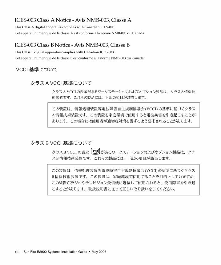
ICES-003 Class A Notice - Avis NMB-003, Classe AThis Class A digital apparatus complies with Canadian ICES-003.
Cet appareil numérique de la classe A est conforme à la norme NMB-003 du Canada.
ICES-003 Class B Notice - Avis NMB-003, Classe BThis Class B digital apparatus complies with Canadian ICES-003.
Cet appareil numérique de la classe B est conforme à la norme NMB-003 du Canada.
xii Sun Fire E2900 Systems Installation Guide • May 2006
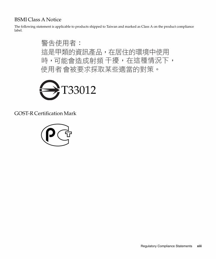
BSMI Class A NoticeThe following statement is applicable to products shipped to Taiwan and marked as Class A on the product compliancelabel.
GOST-R Certification Mark
T33012
Regulatory Compliance Statements xiii

xiv Sun Fire E2900 Systems Installation Guide • May 2006

Safety Agency ComplianceStatementsRead this section before beginning any procedure. Thefollowing text provides safety precautions to follow wheninstalling a Sun Microsystems product.
Safety PrecautionsFor your protection, observe the following safetyprecautions when setting up your equipment:
■ Follow all cautions and instructions marked on theequipment.
■ Ensure that the voltage and frequency of your powersource match the voltage and frequency inscribed onthe equipment’s electrical rating label.
■ Never push objects of any kind through openings inthe equipment. Dangerous voltages may be present.Conductive foreign objects could produce a shortcircuit that could cause fire, electric shock, or damageto your equipment.
SymbolsThe following symbols may appear in this book:
Caution – There is a risk of personal injuryand equipment damage. Follow theinstructions.
Caution – Hot surface. Avoid contact.Surfaces are hot and may cause personalinjury if touched.
Caution – Hazardous voltages are present. Toreduce the risk of electric shock and danger topersonal health, follow the instructions.
Depending on the type of power switch your device has,one of the following symbols may be used:
On – Applies AC power to the system.
Off – Removes AC power from the system.
Standby – The On/Standby switch is in thestandby position.
Modifications to EquipmentDo not make mechanical or electrical modifications to theequipment. Sun Microsystems is not responsible forregulatory compliance of a modified Sun product.
Placement of a Sun Product
Caution – Do not block or cover the openingsof your Sun product. Never place a Sunproduct near a radiator or heat register.Failure to follow these guidelines can causeoverheating and affect the reliability of yourSun product.
Noise LevelIn compliance with the requirements defined in DIN 45635Part 1000, the workplace-dependent noise level of thisproduct is less than 70 db(A).
xv
SELV ComplianceSafety status of I/O connections comply to SELVrequirements.
Power Cord Connection
Caution – Sun products are designed to workwith power systems having a groundedneutral (grounded return for DC-poweredproducts). To reduce the risk of electric shock,do not plug Sun products into any other typeof power system. Contact your facilitiesmanager or a qualified electrician if you arenot sure what type of power is supplied toyour building.
Caution – Not all power cords have the samecurrent ratings. Household extension cords donot have overload protection and are notmeant for use with computer systems. Do notuse household extension cords with your Sunproduct.
The following caution applies only to devices with aStandby power switch:
Caution – The power switch of this productfunctions as a standby type device only. Thepower cord serves as the primary disconnectdevice for the system. Be sure to plug thepower cord into a grounded power outlet thatis nearby the system and is readily accessible.Do not connect the power cord when thepower supply has been removed from thesystem chassis.
The following caution applies only to devices with multiplepower cords:
Caution – For products with multiple powercords, all power cords must be disconnectedto completely remove power from the system.
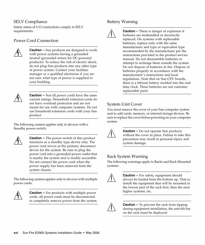
Battery Warning
Caution – There is danger of explosion ifbatteries are mishandled or incorrectlyreplaced. On systems with replaceablebatteries, replace only with the samemanufacturer and type or equivalent typerecommended by the manufacturer per theinstructions provided in the product servicemanual. Do not disassemble batteries orattempt to recharge them outside the system.Do not dispose of batteries in fire. Dispose ofbatteries properly in accordance with themanufacturer’s instructions and localregulations. Note that on Sun CPU boards,there is a lithium battery molded into the real-time clock. These batteries are not customerreplaceable parts.
System Unit CoverYou must remove the cover of your Sun computer systemunit to add cards, memory, or internal storage devices. Besure to replace the cover before powering on your computersystem.
Caution – Do not operate Sun productswithout the cover in place. Failure to take thisprecaution may result in personal injury andsystem damage.
Rack System WarningThe following warnings apply to Racks and Rack Mountedsystems.
Caution – For safety, equipment shouldalways be loaded from the bottom up. That is,install the equipment that will be mounted inthe lowest part of the rack first, then the nexthigher systems, etc.
Caution – To prevent the rack from tippingduring equipment installation, the anti-tilt baron the rack must be deployed.
xvi Sun Fire E2900 Systems Installation Guide • May 2006
Caution – To prevent extreme operatingtemperature within the rack insure that themaximum temperature does not exceed theproduct’s ambient rated temperatures.
Caution – To prevent extreme operatingtemperatures due to reduced airflowconsideration should be made to the amountof air flow that is required for a safe operationof the equipment.
Laser Compliance NoticeSun products that use laser technology comply with Class 1laser requirements.
CD and DVD DevicesThe following caution applies to CD, DVD, and otheroptical devices.
Caution – Use of controls, adjustments, or theperformance of procedures other than thosespecified herein may result in hazardousradiation exposure.
Conformité aux normes de sécuritéVeuillez lire attentivement cette section avant decommencer. Ce texte traite des mesures de sécurité qu’ilconvient de prendre pour l’installation d’un produit SunMicrosystems.
Mesures de sécuritéPour votre sécurité, nous vous recommandons de suivrescrupuleusement les mesures de sécurité ci-dessous lorsquevous installez votre matériel:
■ Suivez tous les avertissements et toutes lesinstructions inscrites sur le matériel.
■ Assurez-vous que la tension et la fréquence de votresource d'alimentation correspondent à la tension et àla fréquence indiquées sur l'étiquette de la tensionélectrique nominale du matériel
■ N'introduisez jamais d'objets quels qu'ils soient dansles ouvertures de l'équipement. Vous pourriez voustrouver en présence de hautes tensions dangereuses.Tout objet étranger conducteur risque de produire uncourt-circuit pouvant présenter un risque d'incendieou de décharge électrique, ou susceptibled'endommager le matériel.
SymbolesVous trouverez ci-dessous la signification des différentssymboles utilisés:
Attention – Vous risquez d'endommager lematériel ou de vous blesser. Veuillez suivre lesinstructions.
Attention – Surfaces brûlantes. Evitez toutcontact. Les surfaces sont brûlantes. Vousrisquez de vous blesser si vous les touchez.
Attention – Tensions dangereuses. Pourréduire les risques de décharge électrique etde danger physique, observez les consignesindiquées.
Class 1 Laser ProductLuokan 1 Laserlaite
Klasse 1 Laser ApparatLaser Klasse 1
Safety Agency Compliance Statements xvii
Selon le type d'interrupteur marche/arrêt dont votreappareil est équipé, l'un des symboles suivants sera utilisé:
Marche – Met le système sous tensionalternative.
Arret – Met le système hors tensionalternative.
Veilleuse – L'interrupteur Marche/Veille estsur la position de veille.
Modification du matérielN'apportez aucune modification mécanique ou électriqueau matériel. Sun Microsystems décline toute responsabilitéquant à la non-conformité éventuelle d'un produit Sunmodifié.
Positionnement d’un produit Sun
Attention – Evitez d'obstruer ou de recouvrirles orifices de votre produit Sun. N'installezjamais un produit Sun près d'un radiateur oud'une source de chaleur. Si vous ne respectezpas ces consignes, votre produit Sun risque desurchauffer et son fonctionnement en seraaltéré.
Niveau de pression acoustiqueLe niveau de pression acoustique du lieu de travail définiepar la norme DIN 45 635 Part 1000 doit être au maximum de70 db(A).
Conformité SELVLe niveau de sécurité des connexions E/S est conforme auxnormes SELV.
Connexion du cordon d’alimentation
Attention – Les produits Sun sont conçuspour fonctionner avec des systèmesd'alimentation équipés d'un conducteurneutre relié à la terre (conducteur neutre pourproduits alimentés en CC). Pour réduire lesrisques de décharge électrique, ne branchezjamais les produits Sun sur une sourced'alimentation d'un autre type. Contactez legérant de votre bâtiment ou un électricienagréé si vous avez le moindre doute quant autype d'alimentation fourni dans votrebâtiment.
Attention – Tous les cordons d'alimentationne présentent pas les mêmes caractéristiquesélectriques. Les cordons d'alimentation àusage domestique ne sont pas protégés contreles surtensions et ne sont pas conçus pour êtreutilisés avec des ordinateurs. N'utilisez jamaisde cordon d'alimentation à usage domestiqueavec les produits Sun.
L'avertissement suivant s'applique uniquement auxsystèmes équipés d'un interrupteur Veille:
Attention – L'interrupteur d'alimentation dece produit fonctionne uniquement comme undispositif de mise en veille. Le cordond'alimentation constitue le moyen principal dedéconnexion de l'alimentation pour lesystème. Assurez-vous de le brancher dansune prise d'alimentation mise à la terre prèsdu système et facile d'accès. Ne le branchezpas lorsque l'alimentation électrique ne setrouve pas dans le châssis du système.
L'avertissement suivant s'applique uniquement auxsystèmes équipés de plusieurs cordons d'alimentation:
Attention – Pour mettre un système équipé deplusieurs cordons d'alimentation hors tension,il est nécessaire de débrancher tous lescordons d'alimentation.
xviii Sun Fire E2900 Systems Installation Guide • May 2006

Mise en garde relative aux batteries
Attention – Les batteries risquent d’exploseren cas de manipulation maladroite ou deremplacement incorrect. Pour les systèmesdont les batteries sont remplaçables, effectuezles remplacements uniquement selon lemodèle du fabricant ou un modèle équivalentrecommandé par le fabricant, conformémentaux instructions fournies dans le manuel deservice du système. N’essayez en aucun cas dedémonter les batteries, ni de les recharger horsdu système. Ne les jetez pas au feu. Mettez-lesau rebut selon les instructions du fabricant etconformément à la législation locale envigueur. Notez que sur les cartes processeurde Sun, une batterie au lithium a été mouléedans l'horloge temps réel. Les batteries ne sontpas des pièces remplaçables par le client.
Couvercle de l'unitéPour ajouter des cartes, de la mémoire ou des périphériquesde stockage internes, vous devez retirer le couvercle devotre système Sun. Remettez le couvercle supérieur enplace avant de mettre votre système sous tension.
Attention – Ne mettez jamais des produitsSun sous tension si leur couvercle supérieurn'est pas mis en place. Si vous ne prenez pasces précautions, vous risquez de vous blesserou d'endommager le système.
Mise en garde relative au système en rackLa mise en garde suivante s'applique aux racks et auxsystèmes montés en rack.
Attention – Pour des raisons de sécurité, lematériel doit toujours être chargé du bas versle haut. En d'autres termes, vous devezinstaller, en premier, le matériel qui doit setrouver dans la partie la plus inférieure durack, puis installer le matériel sur le niveausuivant, etc.
Attention – Afin d'éviter que le rack nepenche pendant l'installation du matériel, tirezla barre anti-basculement du rack.
Attention – Pour éviter des températures defonctionnement extrêmes dans le rack,assurez-vous que la température maximale nedépasse pas la fourchette de températuresambiantes du produit déterminée par lefabricant.
Attention – Afin d'empêcher destempératures de fonctionnement extrêmesprovoquées par une aération insuffisante,assurez-vous de fournir une aérationappropriée pour un fonctionnement dumatériel en toute sécurité
Avis de conformité des appareils laserLes produits Sun qui font appel aux technologies lasers sontconformes aux normes de la classe 1 en la matière.
Périphériques CD et DVDL'avertissement suivant s'applique aux périphériques CD,DVD et autres périphériques optiques:
Attention – L'utilisation de contrôles et deréglages ou l'application de procédures autresque ceux spécifiés dans le présent documentpeuvent entraîner une exposition à desradiations dangereuses.
Class 1 Laser ProductLuokan 1 Laserlaite
Klasse 1 Laser ApparatLaser Klasse 1
Safety Agency Compliance Statements xix

Einhaltung sicherheitsbehördlicherVorschriftenLesen Sie vor dem Ausführen von Arbeiten diesenAbschnitt. Im folgenden Text werden Sicherheitsvor-kehrungen beschrieben, die Sie bei der Installation einesSun Microsystems-Produkts beachten müssen.
SicherheitsvorkehrungenTreffen Sie zu Ihrem eigenen Schutz bei der Installation desGeräts die folgenden Sicherheitsvorkehrungen:
■ Beachten Sie alle auf den Geräten angebrachtenWarnhinweise und Anweisungen.
■ Stellen Sie sicher, dass Spannung und Frequenz derStromversorgung den Nennleistungen auf dem amGerät angebrachten Etikett entsprechen.
■ Führen Sie niemals Fremdobjekte in die Öffnungenam Gerät ein. Es können gefährliche Spannungenanliegen. Leitfähige Fremdobjekte können einenKurzschluss verursachen, der einen Brand, Strom-schlag oder Geräteschaden herbeiführen kann.
SymboleDie Symbole in diesem Handbuch haben folgendeBedeutung:
Achtung – Gefahr von Verletzung undGeräteschaden. Befolgen Sie die Anwei-sungen.
Achtung – Heiße Oberfläche. Nicht berühren,da Verletzungsgefahr durch heiße Oberflächebesteht.
Achtung – Gefährliche Spannungen. BefolgenSie die Anweisungen, um Stromschläge undVerletzungen zu vermeiden.
Je nach Netzschaltertyp an Ihrem Gerät kann eines derfolgenden Symbole verwendet werden:
Ein – Versorgt das System mit Wechselstrom.
Aus– Unterbricht die Wechselstromzufuhrzum Gerät.
Wartezustand – Der Ein-/Standby-Netz-schalter befindet sich in der Standby-Position.
Modifikationen des GerätsNehmen Sie keine elektrischen oder mechanischenGerätemodifikationen vor. Sun Microsystems ist für dieEinhaltung der Sicherheitsvorschriften von modifiziertenSun-Produkten nicht haftbar.
Aufstellung von Sun-Geräten
Achtung – Geräteöffnungen Ihres Sun-Produkts dürfen nicht blockiert oderabgedeckt werden. Sun-Geräte sollten niemalsin der Nähe von Heizkörpern oder Heißluft-klappen aufgestellt werden. Die Nichtbeach-tung dieser Richtlinien kann Überhitzungverursachen und die Zuverlässigkeit IhresSun-Geräts beeinträchtigen.
LautstärkeGemäß den in DIN 45 635 Teil 1000 definierten Vorschriftenbeträgt die arbeitsplatzbedingte Lautstärke dieses Produktsweniger als 70 dB(A).
SELV-KonformitätDer Sicherheitsstatus der E/A-Verbindungen entsprichtden SELV-Anforderungen.
xx Sun Fire E2900 Systems Installation Guide • May 2006

Anschluss des Netzkabels
Achtung – Sun-Geräte sind fürStromversorgungssysteme mit einemgeerdeten neutralen Leiter (geerdeterRückleiter bei gleichstrombetriebenenGeräten) ausgelegt. Um die Gefahr vonStromschlägen zu vermeiden, schließen Siedas Gerät niemals an andere Stromversor-gungssysteme an. Wenden Sie sich an denzuständigen Gebäudeverwalter oder an einenqualifizierten Elektriker, wenn Sie nicht sicherwissen, an welche Art von Stromversor-gungssystem Ihr Gebäude angeschlossen ist.
Achtung – Nicht alle Netzkabel verfügenüber die gleichen Nennwerte. Herkömmliche,im Haushalt verwendete Verlängerungskabelbesitzen keinen Überlastschutz und sinddaher für Computersysteme nicht geeignet.Verwenden Sie bei Ihrem Sun-Produkt keineHaushalts-Verlängerungskabel.
Die folgende Warnung gilt nur für Geräte mit Standby-Netzschalter:
Achtung – Beim Netzschalter dieses Gerätshandelt es sich nur um einen Ein/Standby-Schalter. Zum völligen Abtrennen des Systemsvon der Stromversorgung dient hauptsächlichdas Netzkabel. Stellen Sie sicher, dass dasNetzkabel an eine frei zugängliche geerdeteSteckdose in der Nähe des Systems ange-schlossen ist. Schließen Sie das Stromkabelnicht an, wenn die Stromversorgung vomSystemchassis entfernt wurde.
Die folgende Warnung gilt nur für Geräte mit mehrerenNetzkabeln:
Achtung – Bei Produkten mit mehreren Netz-kabeln müssen alle Netzkabel abgetrennt wer-den, um das System völlig von der Stromver-sorgung zu trennen.
Warnung bezüglich Batterien
Achtung – Bei unsachgemäßer Handhabungoder nicht fachgerechtem Austausch derBatterien besteht Explosionsgefahr. Verwen-den Sie bei Systemen mit austauschbarenBatterien ausschließlich Ersatzbatteriendesselben Typs und Herstellers bzw. einenentsprechenden, vom Hersteller gemäß denAnweisungen im Service-Handbuch desProdukts empfohlenen Batterietyp. VersuchenSie nicht, die Batterien auszubauen oderaußerhalb des Systems wiederaufzuladen.Werfen Sie die Batterien nicht ins Feuer.Entsorgen Sie die Batterien entsprechend denAnweisungen des Herstellers und den vor Ortgeltenden Vorschriften. CPU-Karten von Sunverfügen über eine Echtzeituhr mit integrier-ter Lithiumbatterie. Diese Batterie darf nurvon einem qualifizierten Servicetechniker aus-gewechselt werden.
GehäuseabdeckungSie müssen die Abdeckung Ihres Sun-Computersystemsentfernen, um Karten, Speicher oder interne Speichergerätehinzuzufügen. Bringen Sie vor dem Einschalten desSystems die Gehäuseabdeckung wieder an.
Achtung – Nehmen Sie Sun-Geräte nicht ohneAbdeckung in Betrieb. Die Nichtbeachtungdieses Warnhinweises kann Verletzungen oderGeräteschaden zur Folge haben.
Warnungen bezüglich in Racks eingebauterSystemeDie folgenden Warnungen gelten für Racks und in Rackseingebaute Systeme:
Achtung – Aus Sicherheitsgründen solltensämtliche Geräte von unten nach oben inRacks eingebaut werden. Installieren Sie alsozuerst die Geräte, die an der unterstenPosition im Rack eingebaut werden, gefolgtvon den Systemen, die an nächsthöherer Stelleeingebaut werden, usw.
Safety Agency Compliance Statements xxi
Achtung – Verwenden Sie beim Einbau denKippschutz am Rack, um ein Umkippen zuvermeiden.
Achtung – Um extreme Betriebstemperaturenim Rack zu vermeiden, stellen Sie sicher, dassdie Maximaltemperatur die Nennleistung derUmgebungstemperatur für das Produkt nichtüberschreitet
Achtung – Um extreme Betriebstemperaturendurch verringerte Luftzirkulation zu vermei-den, sollte die für den sicheren Betrieb desGeräts erforderliche Luftzirkulation eingesetztwerden.
Hinweis zur Laser-KonformitätSun-Produkte, die die Laser-Technologie verwenden,entsprechen den Laser-Anforderungen der Klasse 1.
CD- und DVD-GeräteDie folgende Warnung gilt für CD-, DVD- und andereoptische Geräte:
Achtung – Die hier nicht aufgeführteVerwendung von Steuerelementen,Anpassungen oder Ausführung vonVorgängen kann eine gefährlicheStrahlenbelastung verursachen.
Normativas de seguridadLea esta sección antes de realizar cualquier operación. Enella se explican las medidas de seguridad que debe tomar alinstalar un producto de Sun Microsystems.
Medidas de seguridadPara su protección, tome las medidas de seguridadsiguientes durante la instalación del equipo:
■ Siga todos los avisos e instrucciones indicados en elequipo.
■ Asegúrese de que el voltaje y frecuencia de la fuentede alimentación coincidan con el voltaje y frecuenciaindicados en la etiqueta de clasificación eléctrica delequipo.
■ No introduzca objetos de ningún tipo por las rejillasdel equipo, ya que puede quedar expuesto a voltajespeligrosos. Los objetos conductores extraños puedenproducir cortocircuitos y, en consecuencia, incendios,descargas eléctricas o daños en el equipo.
SímbolosEn este documento aparecen los siguientes símbolos:
Precaución – Existe el riesgo de que seproduzcan lesiones personales y daños en elequipo. Siga las instrucciones.
Precaución – Superficie caliente. Evite todocontacto. Las superficies están calientes ypueden causar lesiones personales si se tocan.
Precaución – Voltaje peligroso. Para reducirel riesgo de descargas eléctricas y lesionespersonales, siga las instrucciones.
Class 1 Laser ProductLuokan 1 Laserlaite
Klasse 1 Laser ApparatLaser Klasse 1
xxii Sun Fire E2900 Systems Installation Guide • May 2006
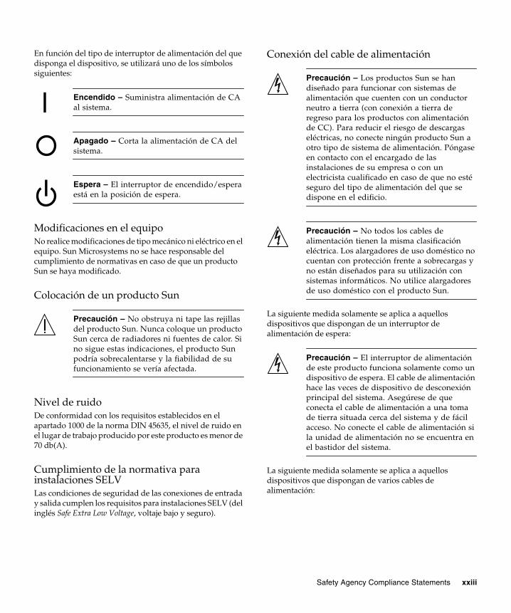
En función del tipo de interruptor de alimentación del quedisponga el dispositivo, se utilizará uno de los símbolossiguientes:
Encendido – Suministra alimentación de CAal sistema.
Apagado – Corta la alimentación de CA delsistema.
Espera – El interruptor de encendido/esperaestá en la posición de espera.
Modificaciones en el equipoNo realice modificaciones de tipo mecánico ni eléctrico en elequipo. Sun Microsystems no se hace responsable delcumplimiento de normativas en caso de que un productoSun se haya modificado.
Colocación de un producto Sun
Precaución – No obstruya ni tape las rejillasdel producto Sun. Nunca coloque un productoSun cerca de radiadores ni fuentes de calor. Sino sigue estas indicaciones, el producto Sunpodría sobrecalentarse y la fiabilidad de sufuncionamiento se vería afectada.
Nivel de ruidoDe conformidad con los requisitos establecidos en elapartado 1000 de la norma DIN 45635, el nivel de ruido enel lugar de trabajo producido por este producto es menor de70 db(A).
Cumplimiento de la normativa parainstalaciones SELVLas condiciones de seguridad de las conexiones de entraday salida cumplen los requisitos para instalaciones SELV (delinglés Safe Extra Low Voltage, voltaje bajo y seguro).
Conexión del cable de alimentación
Precaución – Los productos Sun se handiseñado para funcionar con sistemas dealimentación que cuenten con un conductorneutro a tierra (con conexión a tierra deregreso para los productos con alimentaciónde CC). Para reducir el riesgo de descargaseléctricas, no conecte ningún producto Sun aotro tipo de sistema de alimentación. Póngaseen contacto con el encargado de lasinstalaciones de su empresa o con unelectricista cualificado en caso de que no estéseguro del tipo de alimentación del que sedispone en el edificio.
Precaución – No todos los cables dealimentación tienen la misma clasificacióneléctrica. Los alargadores de uso doméstico nocuentan con protección frente a sobrecargas yno están diseñados para su utilización consistemas informáticos. No utilice alargadoresde uso doméstico con el producto Sun.
La siguiente medida solamente se aplica a aquellosdispositivos que dispongan de un interruptor dealimentación de espera:
Precaución – El interruptor de alimentaciónde este producto funciona solamente como undispositivo de espera. El cable de alimentaciónhace las veces de dispositivo de desconexiónprincipal del sistema. Asegúrese de queconecta el cable de alimentación a una tomade tierra situada cerca del sistema y de fácilacceso. No conecte el cable de alimentación sila unidad de alimentación no se encuentra enel bastidor del sistema.
La siguiente medida solamente se aplica a aquellosdispositivos que dispongan de varios cables dealimentación:
Safety Agency Compliance Statements xxiii
Precaución – En los productos que cuentancon varios cables de alimentación, debedesconectar todos los cables de alimentaciónpara cortar por completo la alimentacióneléctrica del sistema.
Advertencia sobre las baterías
Precaución – Si las baterías no se manipulano reemplazan correctamente, se corre el riesgode que estallen. En los sistemas que cuentancon baterías reemplazables, reemplácelas sólocon baterías del mismo fabricante y el mismotipo, o un tipo equivalente recomendado porel fabricante, de acuerdo con las instruccionesdescritas en el manual de servicio delproducto. No desmonte las baterías ni intenterecargarlas fuera del sistema. No intentedeshacerse de las baterías echándolas al fuego.Deshágase de las baterías correctamente deacuerdo con las instrucciones del fabricante ylas normas locales. Tenga en cuenta que en lasplacas CPU de Sun, hay una batería de litioincorporada en el reloj en tiempo real. Losusuarios no deben reemplazar este tipo debaterías.
Cubierta de la unidad del sistemaDebe extraer la cubierta de la unidad del sistemainformático Sun para instalar tarjetas, memoria odispositivos de almacenamiento internos. Vuelva a colocarla cubierta antes de encender el sistema informático.
Precaución – No ponga en funcionamientolos productos Sun que no tengan colocada lacubierta. De lo contrario, puede sufrir lesionespersonales y ocasionar daños en el sistema.
Advertencia sobre el sistema en bastidorLas advertencias siguientes se aplican a los sistemasmontados en bastidor y a los propios bastidores.
Precaución – Por seguridad, siempre debenmontarse los equipos de abajo arriba. A saber,primero debe instalarse el equipo que sesituará en el bastidor inferior; a continuación,el que se situará en el siguiente nivel, etc.
Precaución – Para evitar que el bastidor sevuelque durante la instalación del equipo,debe extenderse la barra antivolcado delbastidor.
Precaución – Para evitar que se alcance unatemperatura de funcionamiento extrema en elbastidor, asegúrese de que la temperaturamáxima no sea superior a la temperaturaambiente establecida como adecuada para elproducto.
Precaución – Para evitar que se alcance unatemperatura de funcionamiento extremadebido a una circulación de aire reducida,debe considerarse la magnitud de lacirculación de aire requerida para que elequipo funcione de forma segura.
Aviso de cumplimiento de la normativa parala utilización de láserLos productos Sun que utilizan tecnología láser cumplen losrequisitos establecidos para los productos láser de clase 1.
Class 1 Laser ProductLuokan 1 Laserlaite
Klasse 1 Laser ApparatLaser Klasse 1
xxiv Sun Fire E2900 Systems Installation Guide • May 2006
Dispositivos de CD y DVDLa siguiente medida se aplica a los dispositivos de CD yDVD, así como a otros dispositivos ópticos:
Precaución – La utilización de controles,ajustes o procedimientos distintos a los aquíespecificados puede dar lugar a niveles deradiación peligrosos.
Nordic Lithium Battery Cautions
Norge
Advarsel – Litiumbatteri — Eksplosjonsfare.Ved utskifting benyttes kun batteri somanbefalt av apparatfabrikanten. Brukt batterireturneres apparatleverandøren.
Sverige
Varning – Explosionsfara vid felaktigtbatteribyte. Använd samma batterityp eller enekvivalent typ som rekommenderas avapparattillverkaren. Kassera använt batterienligt fabrikantens instruktion.
Danmark
Advarsel! – Litiumbatteri — Eksplosionsfareved fejlagtig håndtering. Udskiftning må kunske med batteri af samme fabrikat og type.Levér det brugte batteri tilbage tilleverandøren.
Suomi
Varoitus – Paristo voi räjähtää, jos se onvirheellisesti asennettu. Vaihda paristoainoastaan laitevalmistajan suosittelemaantyyppiin. Hävitä käytetty paristo valmistajanohjeiden mukaisesti.
Safety Agency Compliance Statements xxv

xxvi Sun Fire E2900 Systems Installation Guide • May 2006

Preface
This guide describes how to install and set up a Sun Fire™ E2900 system.
How This Book Is OrganizedChapter 1 contains information on installing and cabling the system.
Appendix A describes the connectors on the system.
Related Documentation
Application Title
Administration Sun Fire Entry-level Midrange System Administration Guide
Administration Sun Fire Entry-level Midrange System Controller Command Reference Manual
Service Sun Fire E2900 Systems Service Manual
xxvii

Accessing Sun DocumentationYou can view, print, or purchase a broad selection of Sun documentation, includinglocalized versions, at:
http://www.sun.com/documentation
Contacting Sun Technical SupportIf you have technical questions about this product that are not answered in thisdocument, go to:
http://www.sun.com/service/contacting
Sun Welcomes Your CommentsSun is interested in improving its documentation and welcomes your comments andsuggestions. You can submit your comments by going to:
http://www.sun.com/hwdocs/feedback
Please include the title and part number of your document with your feedback:
Sun Fire E2900 Systems Installation Guide, part number 817-4053-15
Tools RequiredFor the procedures in this document, you will need these tools:
■ Computer lifting device■ Phillips No. 2 Screwdriver■ 13 mm Wrench■ 8 mm Wrench
xxviii Sun Fire E2900 Systems Installation Guide • May 2006
CHAPTER 1
Physical Installation
Sun Fire E2900 systems can be shipped in several ways:
1. Not in a cabinet and with a slide rail mounting kit for installation in a cabinet
2. Not in a cabinet and intended upon being freestanding
3. Pre-installed in a cabinet
Following is a list of subjects covered. For method 1 begin with Section 1.1,“Installing Slides and Rails” on page 1-2. For methods 2 and 3 begin with Section 1.4,“Installing the Cable Management Arm” on page 1-21.
■ Section 1.1, “Installing Slides and Rails” on page 1-2■ Section 1.2, “Installing the System in a Cabinet” on page 1-13■ Section 1.3, “Installing Slide Rail Locking Nuts” on page 1-19■ Section 1.4, “Installing the Cable Management Arm” on page 1-21■ Section 1.5, “Connecting Sun Fire V1280/Netra 1280 Power Cables” on page 1-30■ Section 1.6, “Connecting Consoles to the System Controller” on page 1-32■ Section 1.7, “Connecting the I/O Assemblies” on page 1-35■ Section 1.8, “Powering On the System” on page 1-35■ Section 1.9, “Powering Off the System” on page 1-36■ Section 1.10, “Installing Additional Hardware” on page 1-36■ Section 1.11, “Installing Additional Peripheral Devices” on page 1-37
1-1
Caution – The cabinet stabilizers (if applicable) must be extended whenever a SunFire V1280/Netra 1280 system is pulled out of the cabinet.
Caution – The Sun Fire V1280/Netra 1280 system, with mounting cradle, weighsapproximately 286 lb (130 kg). Two people using a computer equipment lift arerequired to move the system safely into the cabinet.
Caution – Pull only one Sun Fire V1280/Netra 1280 system out of the cabinet at atime to prevent unbalancing the cabinet.
1.1 Installing Slides and RailsSystems which are to be mounted in a cabinet utilize a slide rail mounting kit. Thiskit includes the following:
■ Two slide lock spacers■ Two slide lock nuts■ Four rails, two inner and two outer■ 8 MM. wrench
Note – If you received your system pre-installed in a cabinet you may proceeddirectly to Section 1.4, “Installing the Cable Management Arm” on page 1-21.
This section is divided into the following:
■ Section 1.1.1, “Adjusting the Rail Assembly” on page 1-3■ Section 1.1.2, “Installing the Inner Slides on the System” on page 1-4■ Section 1.1.3, “Preparing the Rails for Two-Post Installations” on page 1-6■ Section 1.1.4, “Installing the Rail Assemblies in a Sun Fire/StorEdge Cabinet” on
page 1-7■ Section 1.1.5, “Installing the Rail Assemblies in a Sun Rack 900 Cabinet” on
page 1-9■ Section 1.1.6, “Installing the Rail Assemblies in a 19-Inch Four-Post Cabinet” on
page 1-11■ Section 1.1.7, “Installing the Rail Assemblies in a 19-inch Two-Post Rack” on
page 1-12
1-2 Sun Fire E2900 Systems Installation Guide • May 2006
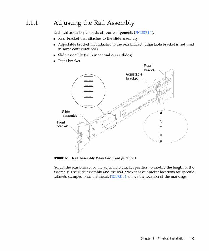
1.1.1 Adjusting the Rail AssemblyEach rail assembly consists of four components (FIGURE 1-1):
■ Rear bracket that attaches to the slide assembly
■ Adjustable bracket that attaches to the rear bracket (adjustable bracket is not usedin some configurations)
■ Slide assembly (with inner and outer slides)
■ Front bracket
FIGURE 1-1 Rail Assembly (Standard Configuration)
Adjust the rear bracket or the adjustable bracket position to modify the length of theassembly. The slide assembly and the rear bracket have bracket locations for specificcabinets stamped onto the metal. FIGURE 1-1 shows the location of the markings.
2-Post 3" Position
2-Post 4" Position
2-Post 6" Position
Sunfire Cabinet
NGR Cabinet
Storedge Cabinet
Adjustable
Rear
Front
Slide SUNFIRE
bracket
assembly
bracket
bracket
Chapter 1 Physical Installation 1-3

1.1.2 Installing the Inner Slides on the System1. Remove the inner slide from the slide assembly:
a. Press the latch adjacent to the green latch.
b. Pull the inner slide free from the outer slide/rail assembly.
2. Push up on the inner slide so that the locating tab, on the side of the system, clipsover the cutouts in the slide (FIGURE 1-2).
The spring tab should engage.
Note – The spring clips must be above the system hooks; the lip on the main bodyof the inner slide must engage under and behind the system hook.
3. Secure the inner slide to the system using two 5 x 10 MM. screws for each slide.
4. Repeat Step 1 through Step 3 for the second inner slide.
1-4 Sun Fire E2900 Systems Installation Guide • May 2006
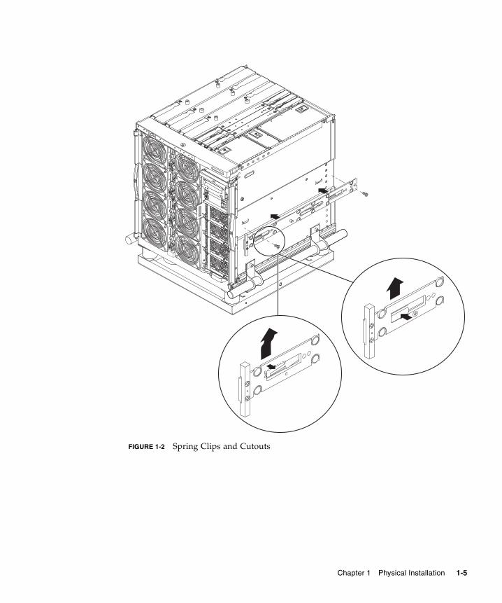
FIGURE 1-2 Spring Clips and Cutouts
Chapter 1 Physical Installation 1-5

1.1.3 Preparing the Rails for Two-Post InstallationsFor two-post installations, you can dismantle and reassemble the rail assemblies(FIGURE 1-3). The rail assemblies can be adjusted to suit a 19-inch two-post rack thathas a post depth in the range of 3 to 6 inches (7.5 to 15.0 cm).
1. Remove the nuts that secure the adjustable bracket and discard the adjustablebracket (FIGURE 1-1).
2. Remove the four nuts securing the front bracket.
3. Rotate the front bracket 180 degrees and secure it facing inward (FIGURE 1-3).
4. Remove the four nuts that secure the rear bracket.
5. Rotate the rear bracket 180 degrees so that it faces inward (FIGURE 1-3).
6. Align the rear bracket to the appropriate markings on the slide assembly andsecure the rear bracket.
7. Repeat Step 1 through Step 6 for the second rail assembly.
FIGURE 1-3 Rail Assembly (Modified for Two-Post Installation)
2-Post 3" Position
2-Post 4" Position
2-Post 6" Position
Sunfire Cabinet
NGR Cabinet
Storedge Cabinet
Rear bracket
Front bracket
(facing inwards)
(facing inwards)
Slide assembly
1-6 Sun Fire E2900 Systems Installation Guide • May 2006

1.1.4 Installing the Rail Assemblies in a SunFire/StorEdge CabinetSun Fire/StorEdge™ cabinets have No. 10-32 UNF tapped screw holes in the frontand rear, which are numbered from bottom to top.
Note – The rail assemblies are reversible. They can be used on either side of thecabinet.
1. Adjust the position of the adjustable bracket on each rail assembly.
a. Loosen the two nuts that secure the adjustable bracket.
b. Reposition the adjustable bracket to the location stamped “SUNFIRE” on therear bracket and secure the adjustable bracket.
2. Adjust the length of each rail assembly.
a. Loosen the four nuts that secure the rear bracket.
b. Reposition the rear bracket to the location marked “Sun Fire Cabinet” on theslide assembly and secure the rear bracket.
1.1.4.1 Installing the Rail Assemblies in the Bottom Position
1. Insert the pins in the front bracket into cabinet holes 22 and 33 (FIGURE 1-4).
The pins will hold the bracket in place until the bracket is secured.
2. Secure the adjustable bracket into cabinet holes 24 and 31 with two No. 10-32 UNFscrews.
3. Secure the front bracket into cabinet holes 24 and 31 with two No. 10-32 UNFscrews.
4. Repeat Step 1 through Step 3 for the second rail assembly.
Note – Mounting the system in cabinet holes 24 and 31 allows for 10-inches of spacebeneath the system in order to service the baseplane.
Chapter 1 Physical Installation 1-7

1.1.4.2 Installing the Rail Assemblies in the Top Position
1. Insert the pins in the front bracket into cabinet holes 58 and 69 (FIGURE 1-4).
The pins will hold the bracket in place until it is secured.
2. Secure the adjustable bracket into cabinet holes 60 and 67 with two No. 10-32 UNFscrews.
3. Secure the front bracket into cabinet holes 60 and 67 with two No. 10-32 UNFscrews.
4. Repeat Step 1 through Step 3 for the second rail assembly.
FIGURE 1-4 Installing the Rails in a Sun Fire Cabinet
Adjustable bracketsecured to inner cabinet holes
Front bracketsecured to outer cabinet holes
1-8 Sun Fire E2900 Systems Installation Guide • May 2006

1.1.5 Installing the Rail Assemblies in a Sun Rack 900CabinetSun™ Rack 900 cabinets have M-6 UNF tapped screw holes in the front and rear thatare numbered from bottom to top.
Note – The rail assemblies are reversible. They can be used on either side of thecabinet.
1. Remove the adjustable bracket on each rail.
a. Loosen the two nuts that secure the adjustable bracket.
b. Discard the adjustable bracket.
2. Adjust the length of each rail assembly.
a. Loosen the four nuts that secure the rear bracket.
b. Reposition the rear bracket to the location marked “NGR Cabinet” on the slideassembly and secure the rear bracket.
1.1.5.1 Installing the Rail Assemblies in the Bottom Position
1. Insert the pins in the front bracket into cabinet holes 22 and 33 (FIGURE 1-5).
The pins will hold the bracket in place until the bracket is secured.
2. Secure the rear bracket into cabinet holes 24 and 31 with two M-6 UNF screws.
3. Secure the front bracket into cabinet holds 24 and 31 with two M-6 UNF screws.
4. Repeat Step 1 through Step 3 for the second rail assembly.
Note – Mounting the system in cabinet holes 24 and 31 allows for 10-inches of spacebeneath the system in order to service the baseplane.
Chapter 1 Physical Installation 1-9
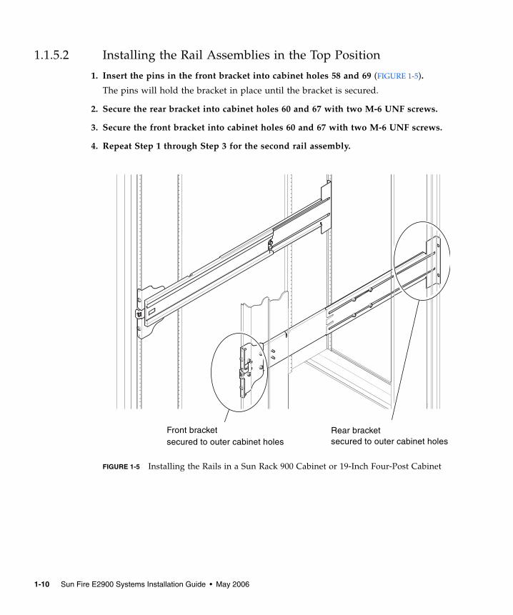
1.1.5.2 Installing the Rail Assemblies in the Top Position
1. Insert the pins in the front bracket into cabinet holes 58 and 69 (FIGURE 1-5).
The pins will hold the bracket in place until the bracket is secured.
2. Secure the rear bracket into cabinet holes 60 and 67 with two M-6 UNF screws.
3. Secure the front bracket into cabinet holes 60 and 67 with two M-6 UNF screws.
4. Repeat Step 1 through Step 3 for the second rail assembly.
FIGURE 1-5 Installing the Rails in a Sun Rack 900 Cabinet or 19-Inch Four-Post Cabinet
Rear bracketsecured to outer cabinet holes
Front bracketsecured to outer cabinet holes
1-10 Sun Fire E2900 Systems Installation Guide • May 2006
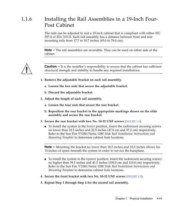
1.1.6 Installing the Rail Assemblies in a 19-Inch Four-Post CabinetThe rails can be adjusted to suit a 19-inch cabinet that is compliant with either IEC297-4 or EIA 310-D. Each rail assembly has a distance between front and rearmounting rails from 17.7 to 30.7 inches (45.0 to 78.0 cm).
Note – The rail assemblies are reversible. They can be used on either side of thecabinet.
Caution – It is the installer’s responsibility to ensure that the cabinet has sufficientstructural strength and stability to handle any required installations.
1. Remove the adjustable bracket on each rail assembly.
a. Loosen the two nuts that secure the adjustable bracket.
b. Discard the adjustable bracket.
2. Adjust the length of each rail assembly.
a. Loosen the four nuts that secure the rear bracket.
b. Reposition the rear bracket to the appropriate markings shown on the slideassembly and secure the rear bracket.
3. Secure the rear bracket with two No. 10-32 UNF screws (FIGURE 1-5).
■ To install the system in the lowest position, insert the rackmount securing screwsno lower than 18.5 inches and 22.5 inches (47.0 cm and 57.2 cm) respectively.Refer to the Sun Fire V1280/Netra 1280 Slide Rail Installation Instructions andMounting Template to determine cabinet hole locations.
Note – Mounting the bracket no lower than 18.5 inches and 22.5 inches allows for10-inches of space beneath the system in order to service the baseplane.
■ To install the system in the topmost position, insert the rackmount securing screwsno higher than 39.5 inches and 43.5 inches (100.0 cm and 110.0 cm) respectively.Refer to the Sun Fire V1280/Netra 1280 Slide Rail Installation Instructions andMounting Template to determine cabinet hole locations.
4. Secure the front bracket with two No. 10-32 UNF screws (FIGURE 1-5).
5. Repeat Step 1 through Step 4 for the second rail assembly.
Chapter 1 Physical Installation 1-11
1.1.7 Installing the Rail Assemblies in a 19-inch Two-Post Rack
Note – The rails assemblies must be prepared. See Section 1.1.3, “Preparing the Railsfor Two-Post Installations” on page 1-6.
Note – The rail assemblies are reversible. They can be used on either side of thecabinet.
Caution – Ensure that the rack is anchored to the floor, ceiling, or adjacent frames.It is the installer’s responsibility to ensure that the rack has sufficient structuralstrength and stability to handle any required installations.
1. Secure the front bracket with two No. 10-32 UNF screws.
Insert the rackmount securing screws no lower than 18.5 inches and 22.5 inches (47.0cm and 57.2 cm) respectively. Refer to the Sun Fire V1280/Netra 1280 Slide RailInstallation Instructions and Mounting Template to determine cabinet hole locations.
Note – Mounting the bracket no lower than 18.5 inches and 22.5 inches allows for10-inches of space beneath the system in order to service the baseplane.
2. Secure the rear bracket with two No. 10-32 UNF screws.
3. Repeat Step 1 and Step 2 for the second rail assembly.
1-12 Sun Fire E2900 Systems Installation Guide • May 2006
1.2 Installing the System in a CabinetThis section contains the following topics:
■ Section 1.2.1, “Preparing to Install the System in the Cabinet” on page 1-13■ Section 1.2.2, “Mounting the System in the Cabinet” on page 1-15
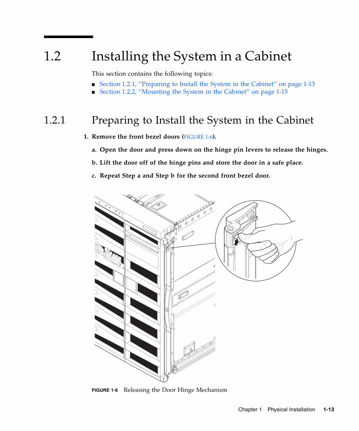
1.2.1 Preparing to Install the System in the Cabinet1. Remove the front bezel doors (FIGURE 1-6).
a. Open the door and press down on the hinge pin levers to release the hinges.
b. Lift the door off of the hinge pins and store the door in a safe place.
c. Repeat Step a and Step b for the second front bezel door.
FIGURE 1-6 Releasing the Door Hinge Mechanism
Chapter 1 Physical Installation 1-13
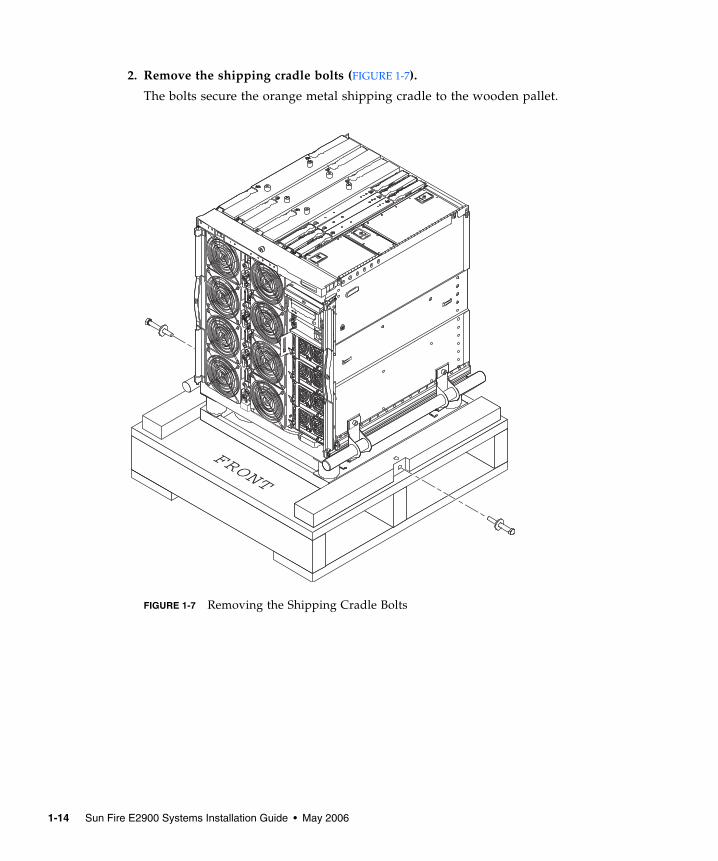
2. Remove the shipping cradle bolts (FIGURE 1-7).
The bolts secure the orange metal shipping cradle to the wooden pallet.
FIGURE 1-7 Removing the Shipping Cradle Bolts
FRONT
1-14 Sun Fire E2900 Systems Installation Guide • May 2006
1.2.2 Mounting the System in the Cabinet
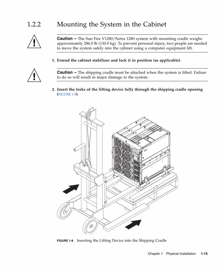
Caution – The Sun Fire V1280/Netra 1280 system with mounting cradle weighsapproximately 286.0 lb (130.0 kg). To prevent personal injury, two people are neededto move the system safely into the cabinet using a computer equipment lift.
1. Extend the cabinet stabilizer and lock it in position (as applicable).
Caution – The shipping cradle must be attached when the system is lifted. Failureto do so will result in major damage to the system.
2. Insert the forks of the lifting device fully through the shipping cradle opening(FIGURE 1-8).
FIGURE 1-8 Inserting the Lifting Device into the Shipping Cradle
FRONT
Chapter 1 Physical Installation 1-15
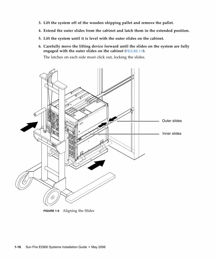
3. Lift the system off of the wooden shipping pallet and remove the pallet.
4. Extend the outer slides from the cabinet and latch them in the extended position.
5. Lift the system until it is level with the outer slides on the cabinet.
6. Carefully move the lifting device forward until the slides on the system are fullyengaged with the outer slides on the cabinet (FIGURE 1-9).
The latches on each side must click out, locking the slides.
FIGURE 1-9 Aligning the Slides
Inner slides
Outer slides
1-16 Sun Fire E2900 Systems Installation Guide • May 2006
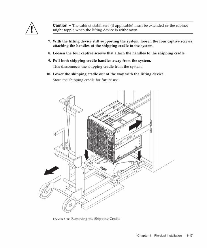
Caution – The cabinet stabilizers (if applicable) must be extended or the cabinetmight topple when the lifting device is withdrawn.
7. With the lifting device still supporting the system, loosen the four captive screwsattaching the handles of the shipping cradle to the system.
8. Loosen the four captive screws that attach the handles to the shipping cradle.
9. Pull both shipping cradle handles away from the system.
This disconnects the shipping cradle from the system.
10. Lower the shipping cradle out of the way with the lifting device.
Store the shipping cradle for future use.
FIGURE 1-10 Removing the Shipping Cradle
Chapter 1 Physical Installation 1-17
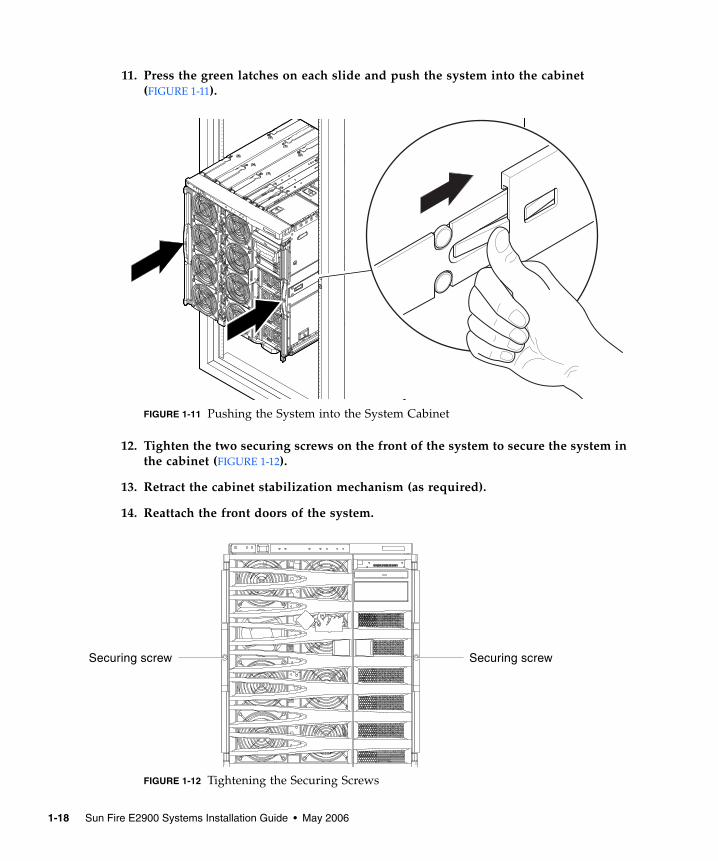
11. Press the green latches on each slide and push the system into the cabinet(FIGURE 1-11).
FIGURE 1-11 Pushing the System into the System Cabinet
12. Tighten the two securing screws on the front of the system to secure the system inthe cabinet (FIGURE 1-12).
13. Retract the cabinet stabilization mechanism (as required).
14. Reattach the front doors of the system.
FIGURE 1-12 Tightening the Securing Screws
Securing screw Securing screw
1-18 Sun Fire E2900 Systems Installation Guide • May 2006
1.3 Installing Slide Rail Locking Nuts
Note – Slide rail locking nuts are pre installed on all units shipped from the factoryin a cabinet.
For systems not shipped pre installed in a cabinet, a slide rail mounting kit isutilized that contains slide rail locking nuts, spacer and rails that are used to mountand secure a system in a cabinet, see Section 1.1, “Installing Slides and Rails” onpage 1-2. Once locking nuts are installed on a system, the following is applicable:
■ Slide rail locking nuts must be loosened in order to remove a system from acabinet
■ Slide rail locking nuts must be securely tightened on each system prior to movinga cabinet with one or more systems
Proceed as follows to install the slide rail locking nuts:
Note – The slide rail mounting kits contain a pair of spacers provided by themanufacturer along with the rails. The manufacturer’s spacers must be discardedand replaced by the Sun spacers provided in the kit.
1. Slide the system out of the system cabinet.
2. Remove and discard the manufactures spacers provided with the slide rails in thekit.
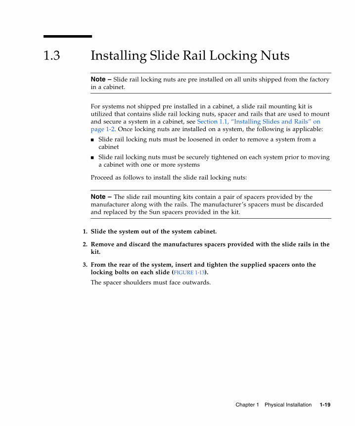
3. From the rear of the system, insert and tighten the supplied spacers onto thelocking bolts on each slide (FIGURE 1-13).
The spacer shoulders must face outwards.
Chapter 1 Physical Installation 1-19
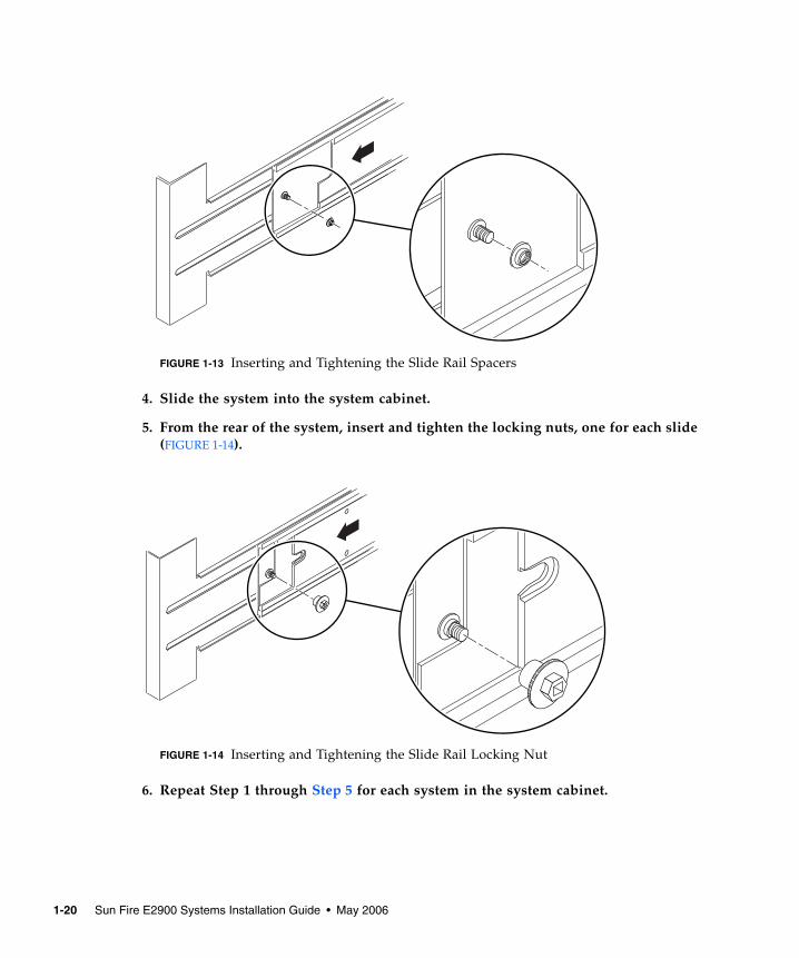
FIGURE 1-13 Inserting and Tightening the Slide Rail Spacers
4. Slide the system into the system cabinet.
5. From the rear of the system, insert and tighten the locking nuts, one for each slide(FIGURE 1-14).
FIGURE 1-14 Inserting and Tightening the Slide Rail Locking Nut
6. Repeat Step 1 through Step 5 for each system in the system cabinet.
1-20 Sun Fire E2900 Systems Installation Guide • May 2006

1.4 Installing the Cable Management ArmThis section contains the following topics:
■ Section 1.4.1, “Installing the CMA–Lite” on page 1-22■ Section 1.4.2, “Installing the CMA–800.” on page 1-23
The purpose of a cable management arm (CMA) is to support and protect cableswhen a system slides into or out of a cabinet.
Two cable management arm solutions are offered: CMA-Lite and CMA-800. Theoptimum choice of CMA is dependant upon the available depth in the cabinet andthe quantity or type of cable to be supported. Use the CMA-Lite if the larger CMA-800 management arm does not fit your cabinet.
Threaded holes for attaching the CMA are provided on the rear of the system(FIGURE 1-15).
FIGURE 1-15 Bracket Mounting Holes
AC
3
AC
2
AC
1
AC
0
SO
UR
CE
AS
OU
RC
E A
SO
UR
CE
B
SC
SI3
AL
AR
MS
BBA
PCI 333MHz
PCI 133MHz
PCI 233MHz
PCI 433MHz
PCI 566MHz
PCI 033MHz
Link
Active
GBit
Link
Active
GBit
NET
0
NET
1
Serial A Serial B
SSC1 SSC1
Upperbracket holes
Lowerbracket holes
Chapter 1 Physical Installation 1-21

1.4.1 Installing the CMA–Lite1. Secure the pivot at the end of the upper arm to the top rear of the system, using
the two captive screws (FIGURE 1-16).
2. Secure the center pivot point of the CMA to the inside rear of the left hand railassembly, using the two captive screws.
3. Secure the pivot at the end of the lower arm to the bottom rear of the system,using the two captive screws.
FIGURE 1-16 CMA–Lite Cable Management Arm
Captivescrews (2)
CMA-LIte
Captivescrews (2)
Captivescrews (2)
1-22 Sun Fire E2900 Systems Installation Guide • May 2006
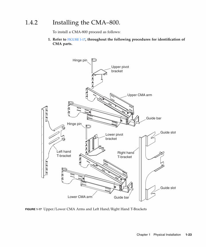
1.4.2 Installing the CMA–800.To install a CMA-800 proceed as follows:
1. Refer to FIGURE 1-17, throughout the following procedures for identification ofCMA parts.
FIGURE 1-17 Upper/Lower CMA Arms and Left Hand/Right Hand T-Brackets
Upper pivot bracket
Hinge pin
Hinge pin
Upper CMA arm
Guide bar
Guide bar
Guide slot
Guide slot
Right handT-bracket
Lower CMA arm
Left handT-bracket
Lower pivot bracket
Chapter 1 Physical Installation 1-23

Note – In the following procedure all left-hand and right-hand orientation is asviewed from the rear of the system chassis.
2. Remove the hinge pin securing the pivot bracket to the upper CMA arm, whichwill facilitate attaching the bracket to the system chassis.
3. Secure the pivot bracket to the upper left hand side of the system chassis using
the two captive screws. See FIGURE 1-18 and FIGURE 1-19.
After attaching the pivot bracket to the chassis, use the hinge pin removedpreviously to secure it to the upper CMA arm.
FIGURE 1-18 Upper/Lower Pivot Bracket Mounting Holes
Upper pivot bracketmounting holes
Upper pivotbracket
Lower pivot bracketmounting holes(hidden)
Lower pivotbracket
1-24 Sun Fire E2900 Systems Installation Guide • May 2006
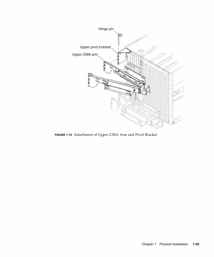
FIGURE 1-19 Attachment of Upper CMA Arm and Pivot Bracket
Upper pivot bracket
Hinge pin
Upper CMA arm
Chapter 1 Physical Installation 1-25
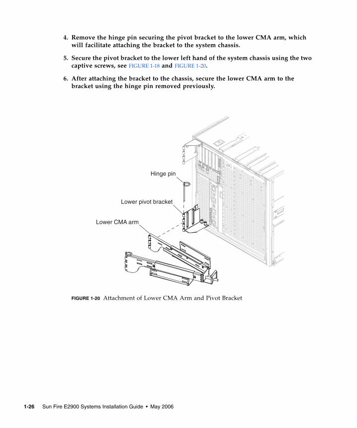
4. Remove the hinge pin securing the pivot bracket to the lower CMA arm, whichwill facilitate attaching the bracket to the system chassis.
5. Secure the pivot bracket to the lower left hand of the system chassis using the twocaptive screws, see FIGURE 1-18 and FIGURE 1-20.
6. After attaching the bracket to the chassis, secure the lower CMA arm to thebracket using the hinge pin removed previously.
FIGURE 1-20 Attachment of Lower CMA Arm and Pivot Bracket
Lower pivot bracket
Hinge pin
Lower CMA arm
1-26 Sun Fire E2900 Systems Installation Guide • May 2006
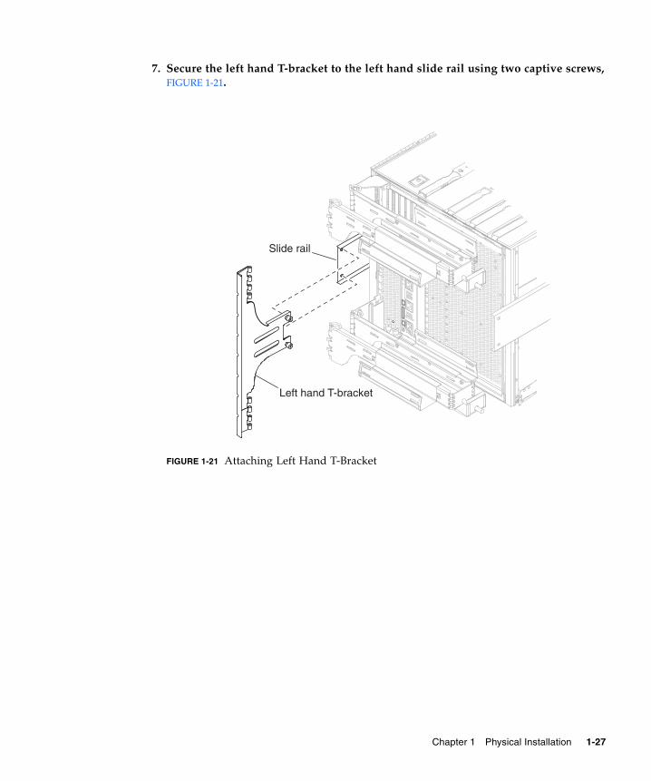
7. Secure the left hand T-bracket to the left hand slide rail using two captive screws,FIGURE 1-21.
FIGURE 1-21 Attaching Left Hand T-Bracket
Slide rail
Left hand T-bracket
Chapter 1 Physical Installation 1-27
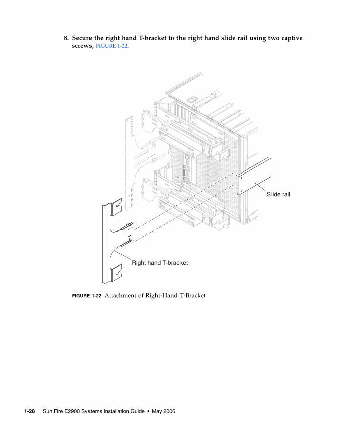
8. Secure the right hand T-bracket to the right hand slide rail using two captivescrews, FIGURE 1-22.
FIGURE 1-22 Attachment of Right-Hand T-Bracket
Slide rail
Right hand T-bracket
1-28 Sun Fire E2900 Systems Installation Guide • May 2006
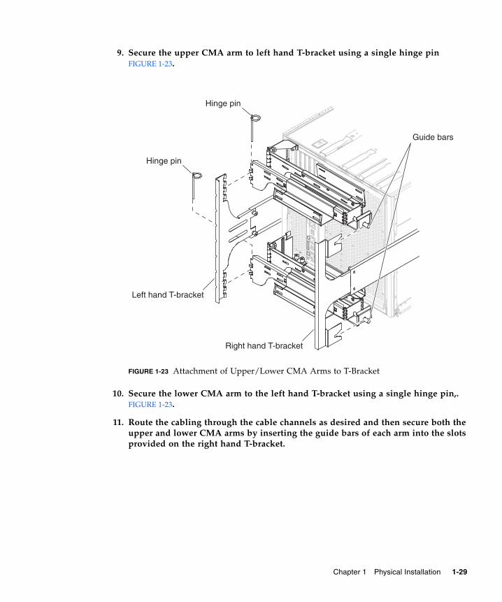
9. Secure the upper CMA arm to left hand T-bracket using a single hinge pinFIGURE 1-23.
FIGURE 1-23 Attachment of Upper/Lower CMA Arms to T-Bracket
10. Secure the lower CMA arm to the left hand T-bracket using a single hinge pin,.FIGURE 1-23.
11. Route the cabling through the cable channels as desired and then secure both theupper and lower CMA arms by inserting the guide bars of each arm into the slotsprovided on the right hand T-bracket.
Hinge pin
Right hand T-bracket
Left hand T-bracket
Guide bars
Hinge pin
Chapter 1 Physical Installation 1-29
1.5 Connecting Sun Fire V1280/Netra 1280Power Cables
Caution – The Sun Fire V1280/Netra 1280 system is designed to work with powersystems having a grounded neutral conductor. Do not connect the equipment intoany other type of power system. Contact your facilities manager or a qualifiedelectrician to determine what type of power is supplied to your building.
Caution – Your Sun product is shipped with grounding-type (three-wire) powercords. Always connect the cords into grounded power outlets.
Caution – The socket outlets must be installed near the equipment and easilyaccessible.
1. Turn the system power switch to the Standby position.
Caution – The On/Standby power switch does not isolate the equipment. The ACpower cords are the primary means of disconnection for this product.
2. Turn the cabinet power off (in a powered cabinet).
Refer to the installation guide that came with the cabinet.
3. Label both ends of the power cords.
Two cords should be labeled Source A and two should be labeled Source B.
4. Connect the power cables to the system.
a. Connect the Source A power cords to AC0 and AC1 on the system and theSource B power cords to AC2 and AC3 on the system.
b. Run the power cords through the CMA and secure them with tie wraps.
Make sure the CMA can extend and retract without dislodging the power cords.
1-30 Sun Fire E2900 Systems Installation Guide • May 2006
Note – Step 3 and Step 4 will already be completed for systems that come preinstalled in a Sun Rack 900 cabinet.
5. Connect the system to the power source.
Note – It is the installer’s responsibility to ensure that the cabinet has sufficientelectrical power and redundancy to handle the required installation.
● If mounted in an unpowered cabinet:
a. Connect power cords from Source A on the system to the customer-suppliedpower source A circuit breakers.
b. Connect power cords from Source B on the system to the customer-suppliedpower source B circuit breakers.
● If mounted in a powered cabinet:
a. Connect power cords from Source A on the cabinet to the customer-suppliedpower source A circuit breakers and Source B on the cabinet to the customer-supplied power source B circuit breakers.
Refer to the installation guide that came with the cabinet for instructions oncabinet power cabling.
b. Connect power cords from Source A on the cabinet to Source A on the systemand Source B on the cabinet to the Source B on the system.
Refer to the installation guide that came with the cabinet for instructions oncabinet power cabling.
Chapter 1 Physical Installation 1-31
1.6 Connecting Consoles to the SystemControllerThis section contains the following topics:
■ Section 1.6.1, “Connecting the Initial Administrative Console” on page 1-33■ Section 1.6.2, “Connecting the Administrative Console” on page 1-35
The system controller (SC) is responsible for providing the Lights-Out Management(LOM) functions, which include power on sequencing, executing module power-onself-tests (POST), environmental monitoring, fault indication and alarms.
The LOM command-line interface and the Solaris/OpenBoot™ PROM console areaccessed by connecting an administrative console to either serial port A or the10/100 LOM Ethernet port. The administrative console can be any external inputdevice (laptop computer or workstation) connected to either of these ports.
Serial port A is used to connect directly to an ASCII terminal or a network terminalserver (NTS) using a command-line interface. This port is used for the initialadministrative console. It is used to modify the default system controller settings(usually so that the 10/100 LOM Ethernet port can be used as an administrativeconsole). The configuration of Serial port A cannot be changed. See Appendix A fordetails on the Serial ports.
The 10/100 LOM Ethernet port is used to connect the system controller to thenetwork. This port is preconfigured as follows:
■ System controller configured to be on a network
■ System controller Ethernet configured for Dynamic Host Configuration Protocol(DHCP)
■ No pre-configured system controller Ethernet IP address, Gateway, Domain namesystem (DNS) domain, DNS servers
1-32 Sun Fire E2900 Systems Installation Guide • May 2006
1.6.1 Connecting the Initial Administrative ConsoleFor the initial configuration, connect Serial A port to the serial port on any of thefollowing devices:
■ ASCII terminal■ Sun workstation■ Terminal server (or patch panel connected to a terminal server)
Note – If the IP address assigned to the 10/100 LOM Ethernet port by DHCP isknown, the 10/100 LOM Ethernet port can be accessed without the Serial A port.
1. Connect the administrative console to the Serial A port.
The Serial A port is a DTE (data terminal equipment) port. An adapter, crossovercable or null modem cable is required to connect the Serial A port to another DTEport. For Serial A port connector pinouts and adaptor information, see Section A.4,“LOM Serial Ports” on page A-6.
2. Turn the customer-supplied circuit breakers power switch to the On position.
3. Turn the system power switch to the On position.
Refer to the Sun Fire Entry-level Midrange System Administration Guide.
4. Set up the administrative console.
Refer to the Sun Fire Entry-level Midrange System Administration Guide.
Chapter 1 Physical Installation 1-33
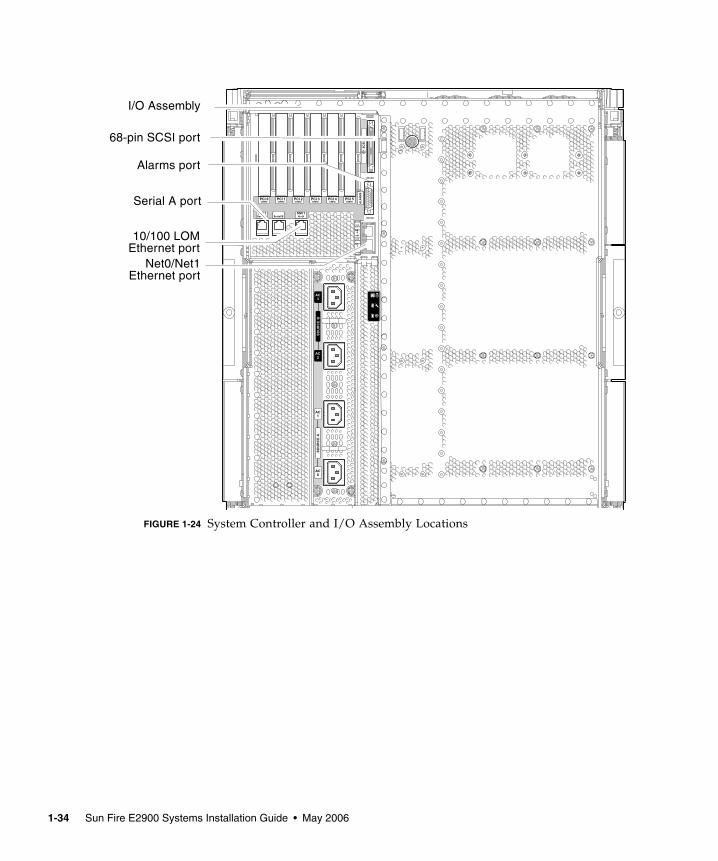
FIGURE 1-24 System Controller and I/O Assembly Locations
AC
3
AC
2
AC
1
AC
0
SO
UR
CE
AS
OU
RC
E A
SO
UR
CE
B
SC
SI3
AL
AR
MS
BBA
PCI 333MHz
PCI 133MHz
PCI 233MHz
PCI 433MHz
PCI 566MHz
PCI 033MHz
Link
Active
GBit
Link
Active
GBit
NET
0
NET
1
Serial A Serial B
SSC1 SSC1
Serial A port
I/O Assembly
Net0/Net1
68-pin SCSI port
Alarms port
10/100 LOMEthernet port
Ethernet port
1-34 Sun Fire E2900 Systems Installation Guide • May 2006
1.6.2 Connecting the Administrative ConsoleOnce the initial configuration is complete, you can perform system administrationtasks directly or over the network using the 10/100 LOM Ethernet port.
Note – Communication on the Serial A port is possible but is subject to interruptionby the LOM device. Refer to the Sun Fire Entry-level Midrange System AdministrationGuide.
1. Connect the 10/100 LOM Ethernet port to the chosen administrative console (localhub, router, or switch).
For 10/100 LOM Ethernet port connector information, see “10/100 LOM EthernetPort” on page A-8.
2. Set up the chosen administrative console.
Refer to the Sun Fire Entry-level Midrange System Administration Guide.
1.7 Connecting the I/O AssembliesThe I/O assemblies provide network interface and peripheral access to the systemdomains.
1. Connect one end of the I/O Ethernet cable to the Net0/Net1 Ethernet port(FIGURE 1-24).
2. Connect the other end of the I/O Ethernet cable to the hub, workstation, orperipheral.
1.8 Powering On the System1. Turn the power switch to the On position.
2. Power on the system.
Refer to the Sun Fire Entry-level Midrange System Administration Guide.
Chapter 1 Physical Installation 1-35

1.9 Powering Off the System1. Notify users that the system is going down.
2. Back up the system files and data to tape, if necessary.
3. Halt the Solaris™ operating system.
Refer to the Sun Fire Entry-level Midrange System Administration Guide.
4. Wait for the system-halted message and the boot monitor prompt.
5. Turn off each external drive and expansion cabinet (as applicable).
6. Turn the power switch to the Standby position.
Caution – The On/Standby power switch does not isolate the equipment. Turningoff the power switch on the customer-supplied circuit breakers is required to isolatethe equipment.
1.10 Installing Additional HardwareDo not install additional hardware until the initial factory configuration has beencompletely installed, the system has been powered on, and POST has beencompleted successfully. This makes it easier to diagnose conflicts that might becaused by additional installations.
Caution – To avoid damaging boards when installing CPU/Memory boards, referto the Sun Fire V1280/Netra 1280 Systems Service Manual for instructions.
Caution – During initial installation, turn off the power at the circuit breakersbefore removing or replacing system hardware. Refer to the installation guide of theadditional hardware for any additional instructions.
For optimum performance, use only I/O cards and associated drivers that arequalified by Sun Microsystems for use on the Sun Fire V1280/Netra 1280 systems. Itis possible for interactions to occur between cards and drivers on a specific bus thatmight lead to potential system panics or other negative outcomes if the card/driver
1-36 Sun Fire E2900 Systems Installation Guide • May 2006
solution is not qualified by Sun Microsystems.
For an updated listing of qualified I/O cards and configurations for the system,contact your Sun authorized sales representative or your service provider. Foradditional information refer to:
http://www.sun.com/io
1.11 Installing Additional Peripheral DevicesWhen you add additional storage devices, refer to the Rackmount Placement Matrix, athttp://docs.sun.com, for the mounting hole numbers of the mounting screwsfor Sun Microsystems disk arrays, other storage trays, and devices.
Unless otherwise specified in the Rackmount Placement Matrix, mount the heaviestsubassemblies at the lowest available opening to minimize the effects of a top-heavysystem in the event of an earthquake.
Refer to the installation guide for the peripheral device for additional instructions.
Chapter 1 Physical Installation 1-37

1-38 Sun Fire E2900 Systems Installation Guide • May 2006
APPENDIX A
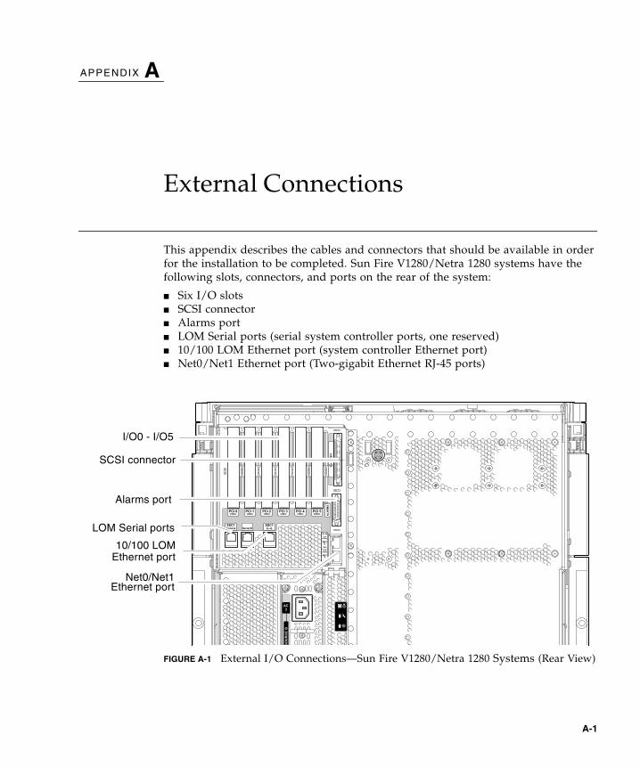
External Connections
This appendix describes the cables and connectors that should be available in orderfor the installation to be completed. Sun Fire V1280/Netra 1280 systems have thefollowing slots, connectors, and ports on the rear of the system:
■ Six I/O slots■ SCSI connector■ Alarms port■ LOM Serial ports (serial system controller ports, one reserved)■ 10/100 LOM Ethernet port (system controller Ethernet port)■ Net0/Net1 Ethernet port (Two-gigabit Ethernet RJ-45 ports)
FIGURE A-1 External I/O Connections—Sun Fire V1280/Netra 1280 Systems (Rear View)
AC
3
SO
UR
CE
AS
OU
RC
E B
SC
SI3
AL
AR
MS
BBA
PCI 333MHz
PCI 133MHz
PCI 233MHz
PCI 433MHz
PCI 566MHz
PCI 033MHz
Link
Active
GBit
Link
Active
GBit
NET
0
NET
1
Serial A Serial B
SSC1 SSC1LOM Serial ports
I/O0 - I/O5
Net0/Net1
SCSI connector
Alarms port
10/100 LOM
Ethernet port
Ethernet port
A-1

A.1 I/O SlotsThere are currently two versions of IB_SSC assemblies, PCI and PCI+. Consult yourSun representative for cards supported by your version of the IB_SSC assembly.
Note – Mixing PCI, PCI+ and PCI-X cards within an IB6 leaf (two slots) is notrecommended since leaf slots run at the lowest speed and the lowest mode for agiven set of cards within a leaf. For example, if a 66 MHz PCI card is in slot 0 and a100 MHz PCI-X card is in slot 1, then both leaf slots will run at the lower 66 MHzPCI speed. IB6 leafs are comprised of paired slots 0 and 1, 2 and 3, and 4 and 5.
A.1.1 PCI IB_SSC AssembliesPCI IB_SSC assemblies provide six I/O slots labeled 0 through 5. When viewing therear of the system, slot 0 is on the left and slot 5 is on the right. Slot 0 supports 66MHz, slots 1-5 support 33 MHz with 5V signaling. The I/O slots are not hotswappable. All slots are half length.
A.1.2 PCI+ IB_SSC AssembliesPCI+ IB_SSC assemblies provide six I/O slots labeled 0 through 5. When viewingthe rear of the system, slot 0 is on the left and slot 5 is on the right. All six slotssupport 33/66 MHz. The I/O slots are not hot swappable, all slots are half lengthand 5V signaling is not supported.
A.1.3 PCI-X IB_SSC AssembliesPCI- X IB_SSC assemblies provide six I/O slots labeled 0 through 5. When viewingthe rear of the system, slot 0 is on the left and slot 5 is on the right. All six slotssupport 33/66/100 MHz. The I/O slots are not hot swappable, all slots are halflength with 3.3V signaling.
A-2 Sun Fire E2900 Systems Installation Guide • May 2006
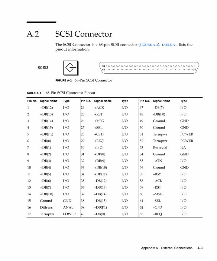
A.2 SCSI ConnectorThe SCSI Connector is a 68-pin SCSI connector (FIGURE A-2). TABLE A-1 lists thepinout information.
FIGURE A-2 68-Pin SCSI Connector
TABLE A-1 68-Pin SCSI Connector Pinout
Pin No. Signal Name Type Pin No. Signal Name Type Pin No. Signal Name Type
1 +DB(12) I/O 24 +ACK I/O 47 –DB(7) I/O
2 +DB(13) I/O 25 +RST I/O 48 -DB(P0) I/O
3 +DB(14) I/O 26 +MSG I/O 49 Ground GND
4 +DB(15) I/O 27 +SEL I/O 50 Ground GND
5 +DB(P1) I/O 28 +C/D I/O 51 Termpwr POWER
6 +DB(0) I/O 29 +REQ I/O 52 Termpwr POWER
7 +DB(1) I/O 30 +I/O I/O 53 Reserved NA
8 +DB(2) I/O 31 +DB(8) I/O 54 Ground GND
9 +DB(3) I/O 32 +DB(9) I/O 55 –ATN I/O
10 +DB(4) I/O 33 +DB(10) I/O 56 Ground GND
11 +DB(5) I/O 34 +DB(11) I/O 57 –BSY I/O
12 +DB(6) I/O 35 –DB(12) I/O 58 –ACK I/O
13 +DB(7) I/O 36 –DB(13) I/O 59 –RST I/O
14 +DB(P0) I/O 37 –DB(14) I/O 60 –MSG I/O
15 Ground GND 38 –DB(15) I/O 61 –SEL I/O
16 Diffsens ANAL 39 –DB(P1) I/O 62 –C/D I/O
17 Termpwr POWER 40 –DB(0) I/O 63 –REQ I/O
3468
135
SCSI3
Appendix A External Connections A-3
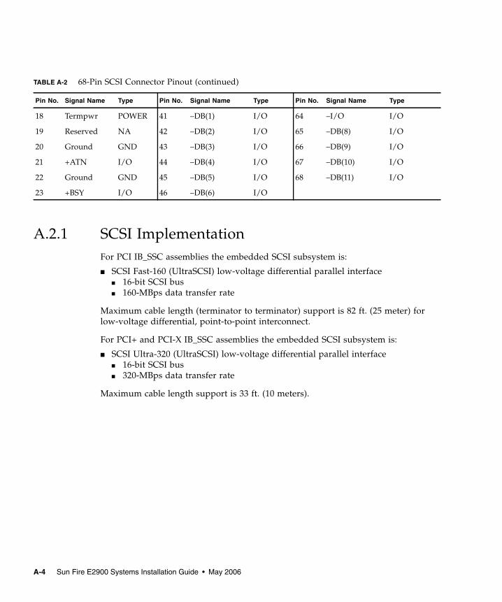
A.2.1 SCSI ImplementationFor PCI IB_SSC assemblies the embedded SCSI subsystem is:
■ SCSI Fast-160 (UltraSCSI) low-voltage differential parallel interface■ 16-bit SCSI bus■ 160-MBps data transfer rate
Maximum cable length (terminator to terminator) support is 82 ft. (25 meter) forlow-voltage differential, point-to-point interconnect.
For PCI+ and PCI-X IB_SSC assemblies the embedded SCSI subsystem is:
■ SCSI Ultra-320 (UltraSCSI) low-voltage differential parallel interface■ 16-bit SCSI bus■ 320-MBps data transfer rate
Maximum cable length support is 33 ft. (10 meters).
TABLE A-2 68-Pin SCSI Connector Pinout (continued)
Pin No. Signal Name Type Pin No. Signal Name Type Pin No. Signal Name Type
18 Termpwr POWER 41 –DB(1) I/O 64 –I/O I/O
19 Reserved NA 42 –DB(2) I/O 65 –DB(8) I/O
20 Ground GND 43 –DB(3) I/O 66 –DB(9) I/O
21 +ATN I/O 44 –DB(4) I/O 67 –DB(10) I/O
22 Ground GND 45 –DB(5) I/O 68 –DB(11) I/O
23 +BSY I/O 46 –DB(6) I/O
A-4 Sun Fire E2900 Systems Installation Guide • May 2006
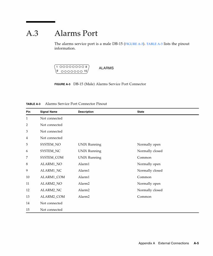
A.3 Alarms PortThe alarms service port is a male DB-15 (FIGURE A-3). TABLE A-3 lists the pinoutinformation.
FIGURE A-3 DB-15 (Male) Alarms Service Port Connector
TABLE A-3 Alarms Service Port Connector Pinout
Pin Signal Name Description State
1 Not connected
2 Not connected
3 Not connected
4 Not connected
5 SYSTEM_NO UNIX Running Normally open
6 SYSTEM_NC UNIX Running Normally closed
7 SYSTEM_COM UNIX Running Common
8 ALARM1_NO Alarm1 Normally open
9 ALARM1_NC Alarm1 Normally closed
10 ALARM1_COM Alarm1 Common
11 ALARM2_NO Alarm2 Normally open
12 ALARM2_NC Alarm2 Normally closed
13 ALARM2_COM Alarm2 Common
14 Not connected
15 Not connected
819 15
ALARMS
Appendix A External Connections A-5
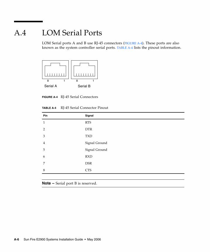
A.4 LOM Serial PortsLOM Serial ports A and B use RJ-45 connectors (FIGURE A-4). These ports are alsoknown as the system controller serial ports. TABLE A-4 lists the pinout information.
FIGURE A-4 RJ-45 Serial Connectors
Note – Serial port B is reserved.
TABLE A-4 RJ-45 Serial Connector Pinout
Pin Signal
1 RTS
2 DTR
3 TXD
4 Signal Ground
5 Signal Ground
6 RXD
7 DSR
8 CTS
Serial A Serial B
1818
A-6 Sun Fire E2900 Systems Installation Guide • May 2006
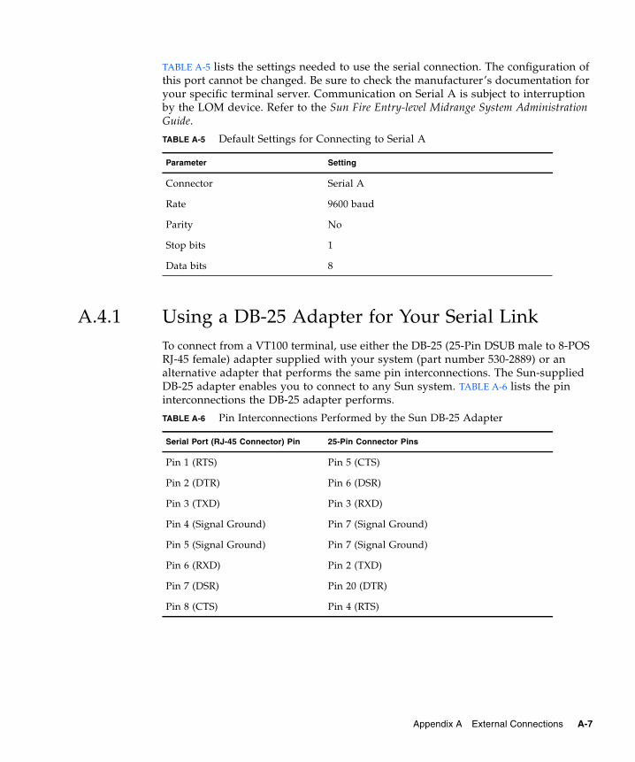
TABLE A-5 lists the settings needed to use the serial connection. The configuration ofthis port cannot be changed. Be sure to check the manufacturer’s documentation foryour specific terminal server. Communication on Serial A is subject to interruptionby the LOM device. Refer to the Sun Fire Entry-level Midrange System AdministrationGuide.
A.4.1 Using a DB-25 Adapter for Your Serial LinkTo connect from a VT100 terminal, use either the DB-25 (25-Pin DSUB male to 8-POSRJ-45 female) adapter supplied with your system (part number 530-2889) or analternative adapter that performs the same pin interconnections. The Sun-suppliedDB-25 adapter enables you to connect to any Sun system. TABLE A-6 lists the pininterconnections the DB-25 adapter performs.
TABLE A-5 Default Settings for Connecting to Serial A
Parameter Setting
Connector Serial A
Rate 9600 baud
Parity No
Stop bits 1
Data bits 8
TABLE A-6 Pin Interconnections Performed by the Sun DB-25 Adapter
Serial Port (RJ-45 Connector) Pin 25-Pin Connector Pins
Pin 1 (RTS) Pin 5 (CTS)
Pin 2 (DTR) Pin 6 (DSR)
Pin 3 (TXD) Pin 3 (RXD)
Pin 4 (Signal Ground) Pin 7 (Signal Ground)
Pin 5 (Signal Ground) Pin 7 (Signal Ground)
Pin 6 (RXD) Pin 2 (TXD)
Pin 7 (DSR) Pin 20 (DTR)
Pin 8 (CTS) Pin 4 (RTS)
Appendix A External Connections A-7
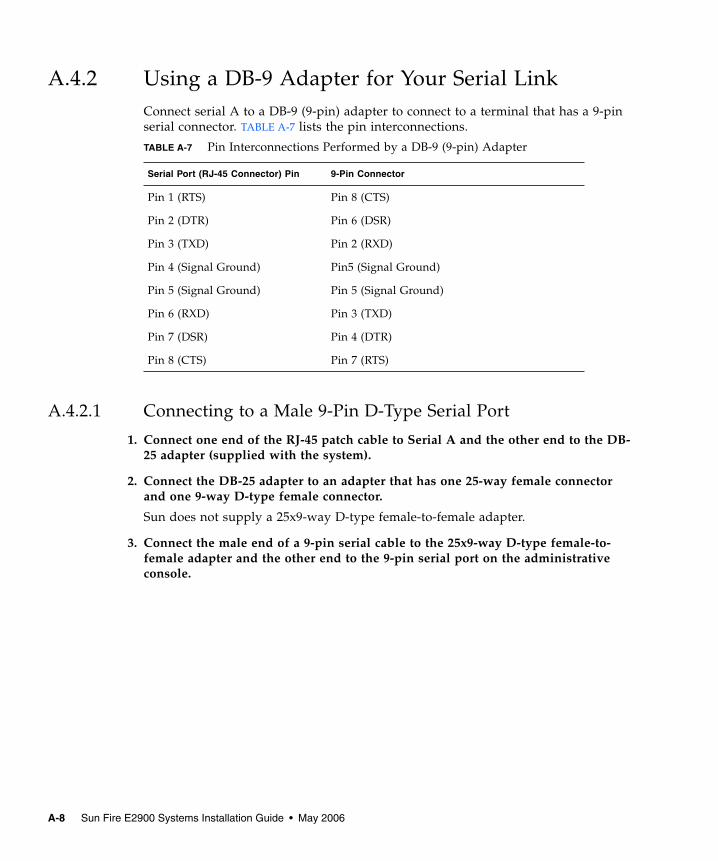
A.4.2 Using a DB-9 Adapter for Your Serial LinkConnect serial A to a DB-9 (9-pin) adapter to connect to a terminal that has a 9-pinserial connector. TABLE A-7 lists the pin interconnections.
A.4.2.1 Connecting to a Male 9-Pin D-Type Serial Port
1. Connect one end of the RJ-45 patch cable to Serial A and the other end to the DB-25 adapter (supplied with the system).
2. Connect the DB-25 adapter to an adapter that has one 25-way female connectorand one 9-way D-type female connector.
Sun does not supply a 25x9-way D-type female-to-female adapter.
3. Connect the male end of a 9-pin serial cable to the 25x9-way D-type female-to-female adapter and the other end to the 9-pin serial port on the administrativeconsole.
TABLE A-7 Pin Interconnections Performed by a DB-9 (9-pin) Adapter
Serial Port (RJ-45 Connector) Pin 9-Pin Connector
Pin 1 (RTS) Pin 8 (CTS)
Pin 2 (DTR) Pin 6 (DSR)
Pin 3 (TXD) Pin 2 (RXD)
Pin 4 (Signal Ground) Pin5 (Signal Ground)
Pin 5 (Signal Ground) Pin 5 (Signal Ground)
Pin 6 (RXD) Pin 3 (TXD)
Pin 7 (DSR) Pin 4 (DTR)
Pin 8 (CTS) Pin 7 (RTS)
A-8 Sun Fire E2900 Systems Installation Guide • May 2006
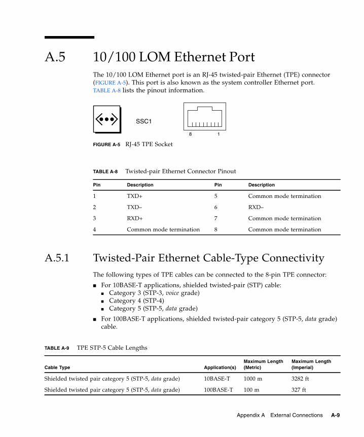
A.5 10/100 LOM Ethernet PortThe 10/100 LOM Ethernet port is an RJ-45 twisted-pair Ethernet (TPE) connector(FIGURE A-5). This port is also known as the system controller Ethernet port.TABLE A-8 lists the pinout information.
FIGURE A-5 RJ-45 TPE Socket
A.5.1 Twisted-Pair Ethernet Cable-Type ConnectivityThe following types of TPE cables can be connected to the 8-pin TPE connector:
■ For 10BASE-T applications, shielded twisted-pair (STP) cable:■ Category 3 (STP-3, voice grade)■ Category 4 (STP-4)■ Category 5 (STP-5, data grade)
■ For 100BASE-T applications, shielded twisted-pair category 5 (STP-5, data grade)cable.
TABLE A-8 Twisted-pair Ethernet Connector Pinout
Pin Description Pin Description
1 TXD+ 5 Common mode termination
2 TXD– 6 RXD–
3 RXD+ 7 Common mode termination
4 Common mode termination 8 Common mode termination
TABLE A-9 TPE STP-5 Cable Lengths
Cable Type Application(s)Maximum Length(Metric)
Maximum Length(Imperial)
Shielded twisted pair category 5 (STP-5, data grade) 10BASE-T 1000 m 3282 ft
Shielded twisted pair category 5 (STP-5, data grade) 100BASE-T 100 m 327 ft
18
SSC1
Appendix A External Connections A-9
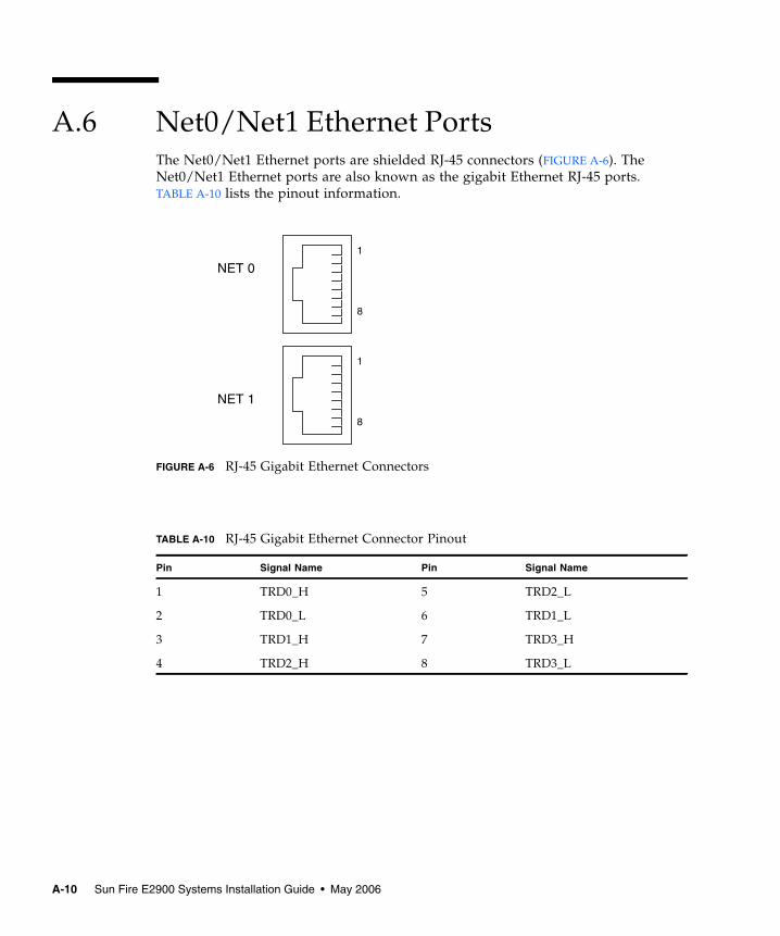
A.6 Net0/Net1 Ethernet PortsThe Net0/Net1 Ethernet ports are shielded RJ-45 connectors (FIGURE A-6). TheNet0/Net1 Ethernet ports are also known as the gigabit Ethernet RJ-45 ports.TABLE A-10 lists the pinout information.
FIGURE A-6 RJ-45 Gigabit Ethernet Connectors
TABLE A-10 RJ-45 Gigabit Ethernet Connector Pinout
Pin Signal Name Pin Signal Name
1 TRD0_H 5 TRD2_L
2 TRD0_L 6 TRD1_L
3 TRD1_H 7 TRD3_H
4 TRD2_H 8 TRD3_L
8
1
8
1
NET 0
NET 1
A-10 Sun Fire E2900 Systems Installation Guide • May 2006