SUMMARY STRENGTH AND STABILITY CALCULATION
5
Document ID: FEM20018-A Date: 09-03-2021 Projectnummer: — Productnummer: — SUMMARY STRENGTH AND STABILITY CALCULATION RS52-S 8,2 meter platformheight Solar lift Calculated according to valid standard: EN 1004 The European Directive “Working at Height” is compulsory within the countries of the European Committee. Based on this, when using rolling tower at work a strength- and stability calculation must be available and in accordance with the applicable standards (state of the art). For mobile access towers the current standard is EN 1004 (Mobile access and working towers made of prefabricated elements - Materials, dimensions, design loads, safety and performance require- ments). Upon purchase this declaration gives the guarantee of a liable working tool. Scope of this summary Altrex B.V. possesses the necessary specialist knowledge to produce and ana- lyze a structural strength and/or stability calculation for standard configurations, Combination Configurations and custom-built products. The output of a calcula- tion is very comprehensive. For that reason, a summary of the calculation has been opted for. If required, the Health and Safety Inspectorate can check the total calculation (results) at Altrex. Declaraon
Transcript of SUMMARY STRENGTH AND STABILITY CALCULATION
Document ID: FEM20018-A
Date: 09-03-2021 Projectnummer: — Productnummer: —
SUMMARY STRENGTH AND
STABILITY CALCULATION
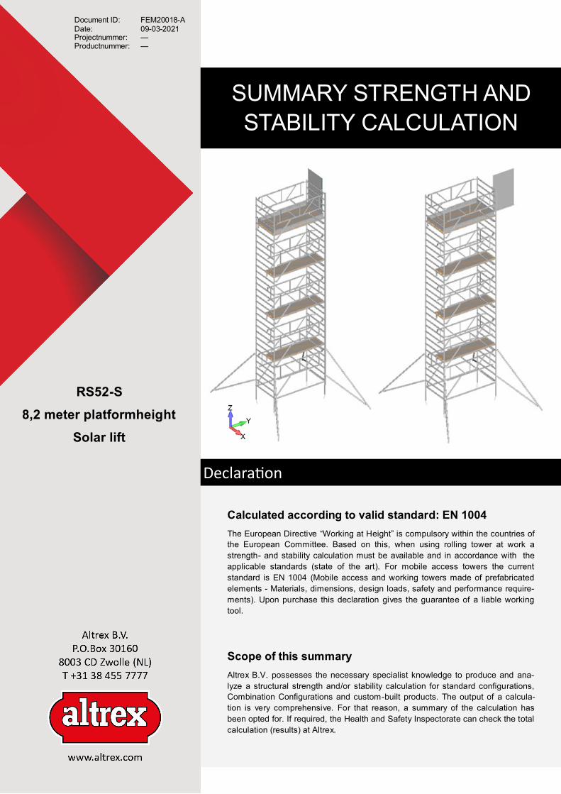
RS52-S
8,2 meter platformheight
Solar lift
Calculated according to valid standard: EN 1004
The European Directive “Working at Height” is compulsory within the countries of
the European Committee. Based on this, when using rolling tower at work a
strength- and stability calculation must be available and in accordance with the
applicable standards (state of the art). For mobile access towers the current
standard is EN 1004 (Mobile access and working towers made of prefabricated
elements - Materials, dimensions, design loads, safety and performance require-
ments). Upon purchase this declaration gives the guarantee of a liable working
tool.
Scope of this summary
Altrex B.V. possesses the necessary specialist knowledge to produce and ana-
lyze a structural strength and/or stability calculation for standard configurations,
Combination Configurations and custom-built products. The output of a calcula-
tion is very comprehensive. For that reason, a summary of the calculation has
been opted for. If required, the Health and Safety Inspectorate can check the total
calculation (results) at Altrex.
Declaration

Method The strength and stability calculations are made by means of the Finite Element Method (FEM). For the calcu-
lations FEMAP (v.10.1.0.) pre-processor/post-processor and NX Nastran is used as solver. Using these pro-
grammes enables you to make the obligatory second-order calculations by means of FEM.
Each rolling tower contains a line-model as basis for the geometry. A precise model consisting of various ele-
ments is obtained by adding the correct characteristics. To this end, different types of elements are used:
- Beam-elements Extruded profiles
- Plate-elements Platforms; wood or fiber
- Rigid-elements Connection components
- Mass-elements Correction of component mass
Wherever necessary, degrees of freedom are applied to simulate a proper connection.
Conditions
The configuration support is simula-
ted by applying constraints in the
FEM model. The wheels of the con-
figuration are simulated by locking
them against displacements in three
directions (X, Y, Z direction), repre-
sented by the numbers 1, 2 & 3.
The configuration is calculated for
two different situations:
Situation 1; The solar panel is lifted,
the solar panel is parallel to the
transverse direction of the scaffol-
ding (see figure 1)
Situation 2; The solar panel is mo-
ved up the scaffolding to the highest
position of the hoist, the solar panel
is parallel to the longitudinal directi-
on of the scaffolding (see figure 1).
The purpose of the calculation is to
determine the maximum wind load
at which the configuration is stable.
Situation 1 Situation 2
Figure 1
Strength calculation
The European standard EN 1004 describes that a mobile scaffold must be able to withstand a combination of
loads. This concerns the following loads:
A. Self weight of the configuration
B. Loads resulting from an inclination of 1%
C. Uniformly distributed load on topmost platform (class 3) qdistr = 2,0 kN/m2
D. Minimum vertical service load Fser. vert = 5,0 kN/4 legs
E. Horizontal service loads (on the level of the platform) Fser. hor = 0,3 kN
F. Windload (5 bft, differs from EN1004) qwind = 0,072 kN/m2
The above loads must be carried out in different combinations. In doing so, safety factors must also be taken
into account. An overview of the different load combinations is shown below.
The above table is used in both the longitudinal direction and the transverse direction of the rolling tower. For
all possible configurations (see configuration overview) all four load combinations are evaluated in the most
unfavorable direction.
Loadcase A B C D E F
1 1,5 1,5 1,5 - 1,5 1,5
2 1,5 1,5 - 1,5 1,5 1,5

Figure 2 shows the most critical occurring stresses of the relevant scaffold ranges. The stresses are evaluated
with respect to their maximum allowable material values. These stresses depend on the base material used
and therefore, can vary per element. Heat Affected Zones (HAZ) are also taken into account by allowing a
reduced maximum value for these elements
The stress values of all calculated configurations are within the permissible limits and therefore, these scaf-
folds comply with the strength criteria formulated in the European standard EN 1004.
Critical stress, non HAZ [N/mm2] Critical stress, HAZ [N/mm2]
Figure 2
Stability calculation, situation 1
The European standard EN 1004 states that for stability a rolling tower should be able to resist a combination
of loads. This includes the following loads:
A. Self-weight of the construction
B. Loads resulting from an inclination of 1%
C. Vertical service load Fser. vert = 0,75 kN
D. Horizontal service loads (on the level of the platform) Fser. hor = 0,3 kN
E. Wind load (5 bft, differs from EN1004) qwind = 0,72 kN/m2
The above loads must be carried out in different combinations. In doing so, safety factors must also be taken
into account. An overview of the different load combinations is shown below.
The above table is used in both the longitudinal direction and the transverse direction of the rolling tower. For
all possible configurations (see configuration overview) all four load combinations are evaluated in the most
unfavorable direction.
Loadcase A B C D E
1 1,0 1,5 1,0 1,5 -
2 1,0 1,5 1,0 - 1,5
3 1,0 1,3 - - 1,3

Figure 3 shows the most critical reaction forces and displacements of the relevant rolling -tower range. The
supports of the rolling tower can only absorb pressure forces. This means that a relevant support (boundary
condition) will be removed from the model in case of a tensile force. This process is repeated up to a minimum
of four supports (two supports of the rolling tower and two of the stabilizers). If this measure proves to be in-
sufficient, then counterweight is added in steps of 5 kg to each leg of the construction. The purpose of this
analysis is obtaining a situation in which there are only pressure forces on the scaffold construction. A rolling
tower is considered stable if all reaction forces are pressure forces.
Reaction forces [N] Displacements [mm]
Figure 3
The European standard EN 1004 states that for stability a rolling tower should be able to resist a combination
of loads. This includes the following loads:
A. Self-weight of the construction
B. Loads resulting from an inclination of 1%
C. Vertical service load Fser. vert = 0,75 kN
D. Horizontal service loads (on the level of the platform) Fser. hor = 0,3 kN
E. Wind load (5 bft, differs from EN1004) qwind = 0,72 kN/m2
The above loads must be carried out in different combinations. In doing so, safety factors must also be taken
into account. An overview of the different load combinations is shown below.
The above table is used in both the longitudinal direction and the transverse direction of the rolling tower. For
all possible configurations (see configuration overview) all four load combinations are evaluated in the most
unfavorable direction.
Stability calculation, situation 2
Loadcase A B C D E
1 1,0 1,5 1,0 1,5 -
2 1,0 1,5 1,0 - 1,5
3 1,0 1,3 - - 1,3

Figure 4 shows the most critical reaction forces and displacements of the relevant rolling -tower range. The
supports of the rolling tower can only absorb pressure forces. This means that a relevant support (boundary
condition) will be removed from the model in case of a tensile force. This process is repeated up to a minimum
of four supports (two supports of the rolling tower and two of the stabilizers). If this measure proves to be in-
sufficient, then counterweight is added in steps of 5 kg to each leg of the construction. The purpose of this
analysis is obtaining a situation in which there are only pressure forces on the scaffold construction. A rolling
tower is considered stable if all reaction forces are pressure forces.
Reaction forces [N] Displacements [mm]
Figure 4
Altrex B.V. copyright © 2021
“All rights reserved. No part of this strength and stability calculation summary may be duplicated, stored in an automated data file, or disclosed in any way of form, whether electroni-
cally, mechanically by photocopying, recording, or in any other way, without prior consent from Altrex B.V. Zwolle. This strength and stability calculation summary may only be used for
Altrex products.”
In this summary of the strength and stability calculation Altrex B.V. declares that the rolling tower RS TOWER
52-S meets the requirements of the European standard EN 1004 (Mobile access and working towers made of
prefabricated elements - Materials, dimensions, design loads, safety and performance requirements), provided
that the rolling tower is assembled and used in accordance with the manual . Regarding the maximum wind
force, the standard EN 1004 has been deviated from. This calculation is based on a maximum wind force of 5
Beaufort instead of 6 Beaufort. For assembly and use, please refer to the manual supplied, including the
quantity of counterweights stated therein.
The solar lift configuration meets the strength criteria: YES
The solar lift configuration meets the stability criteria: YES
Conclusion