
Summary report Sorting plastics for food use food grade sorting...Summary report Sorting plastics...
61
Summary report Sorting plastics for food use Report of a series of trials of techniques for automated sorting of polypropylene plastic packaging for food use Project code: IMT003-103 Research date: July 2011 - March 2012 Date: July 2012
Transcript of Summary report Sorting plastics for food use food grade sorting...Summary report Sorting plastics...
Summary report
Sorting plastics for food use
Report of a series of trials of techniques for automated sorting of polypropylene plastic packaging for food use
Project code: IMT003-103 Research date: July 2011 - March 2012 Date: July 2012

WRAP‟s vision is a world without waste, where resources are used sustainably. We work with businesses and individuals to help them reap the benefits of reducing waste, develop sustainable products and use resources in an efficient way. Find out more at www.wrap.org.uk
Document reference: [e.g. WRAP, 2006, Report Name (WRAP Project TYR009-19. Report prepared by…..Banbury, WRAP]
Written by: Roger Morton, Richard Williams, Shaban Omboke, Liz Morrish
Front cover photography: Laser diffraction pattern created from prototype food contact marker
While we have tried to make sure this report is accurate, we cannot accept responsibility or be held legally responsible for any loss or damage arising out of or in
connection with this information being inaccurate, incomplete or misleading. This material is copyrighted. You can copy it free of charge as long as the material is
accurate and not used in a misleading context. You must identify the source of the material and acknowledge our copyright. You must not use material to endorse or
suggest we have endorsed a commercial product or service. For more details please see our terms and conditions on our website at www.wrap.org.uk

Sorting plastics for food use 1
Executive summary
The purpose of this project was to determine whether a marking and detection technique could be developed to identify food contact plastic packaging in recycling plants. WRAP is working with industry to develop a viable process to recycle polypropylene (PP) packaging waste from households into food grade recycled PP (rPP). This will enable brands and retailers to close the loop by using this material again in new PP food packaging and reduce its‟ carbon impact. In order for food grade rPP to be produced in the UK a technically and commercially viable automated solution is required to sort packaging that has been used with food from that which has not, because food grade recycled plastics must be made from 99% food contact raw material. The reason for this is to prevent substances that have not been approved for use in food contact packaging from being used in food packaging with a recycled content. This separation cannot be done economically by manual sorting so an automated method is required. The technologies investigated are not polymer-specific which means that successful solutions have the potential to also be applied to improve the recycling of polyethylene terephthalate (PET) and high density polyethylene (HDPE) to food grade materials. A wide range of potential marking and detection techniques were considered and from these, three groups of detection techniques were short-listed for practical trials:
Machine readable inks – two types: o Sun Chemical fluorescent pigment; o Systems Labelling machine readable ink;
Induction sensing – three types: o Aluminium foil shapes with conventional sensors; o Printable circuits and materials that create harmonics; o Materials that create a phase shift;
Diffraction gratings – three types: o Injection moulded; o Impression moulded; and o Printed or embossed structures on labels.
The practical work demonstrated that the induction sensing options are less likely to be commercially viable for mass market adoption than the other options considered in this project because:
They may be more expensive to add to high volume packaging;
The sensing technique will require more development by the automated sorting machine makers; and
They contain small amounts of metal – which may create a problem for some food manufacturers who use metal detectors to identify foreign objects on their packing lines.
The initial tests of the machine readable inks were not successful but these options are still worthy of further development because they are potentially the most commercially attractive. Based on the initial work in this project at least one of them appears to be close to technical viability and should require only relatively straightforward development of the detection method for it to be adopted commercially. The diffraction grating tests in this project were successful and demonstrated proof of concept for a technique which could be a low cost and flexible solution for food contact marking of all PP packaging types if it was adopted widely by the food packaging sector. It

Sorting plastics for food use 2
does however require more development of the sensing technology and more packaging development than the pigmented lacquer option. This report recommends a programme of further work that should be pursued to develop both the machine readable ink and diffraction grating food contact marking systems. More effort should be devoted to testing alternative machine readable inks using different illumination techniques. For diffraction gratings a prototype sensing unit should be built to demonstrate sensing at production speed and to test a range of optimised printed, embossed and impression-moulded markers. This demonstration will help provide evidence to retailers, brand owners, packaging designers, recyclers and sorting machine builders to move forward and implement this marking technique.
Sorting plastics for food use 3
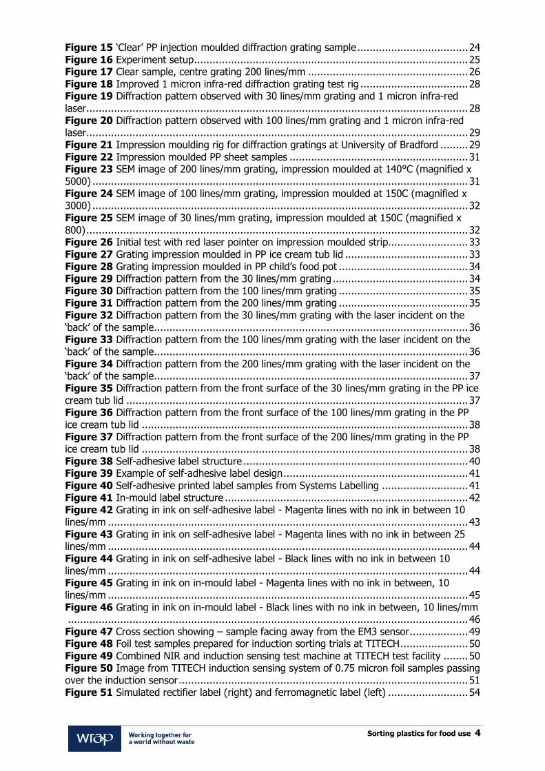
Contents
1. Background .................................................................................................. 6 1.1 Project partners ......................................................................................... 6
1.1.1 WRL Consultancy ............................................................................. 6 1.1.2 Systems Labelling ............................................................................ 6 1.1.3 Sun Chemical ................................................................................... 7 1.1.4 TITECH ........................................................................................... 7 1.1.5 Pellenc Selective Technologies .......................................................... 7 1.1.6 University of Bradford School of Engineering Design and Technology ... 7 1.1.7 University of Durham ....................................................................... 7
2. Why develop a food contact packaging marker? .......................................... 8 2.1 Attributes for a food contact marker ............................................................ 8
3. Marker options considered ......................................................................... 10 3.1 Polymer additives ..................................................................................... 10 3.2 Labels ..................................................................................................... 10 3.3 Surface markings in package moulding or on a label ................................... 12
4. Short listed PP food contact marker options .............................................. 13 5. Lacquered labels ......................................................................................... 14
5.1 Fluorescent pigmented lacquer– Sun Chemical ........................................... 14 5.2 Machine readable lacquer – Systems Labelling ............................................ 15
6. Induction sensing marker options .............................................................. 19 7. Diffraction gratings .................................................................................... 20
7.1 Initial proof of concept work on diffraction gratings .................................... 20 7.2 Further diffraction grating development conducted for this project ............... 27
7.2.1 Longer wavelength laser to improve diffraction pattern definition with coarser grating structures ......................................................................... 27 7.2.2 Alternative grating options .............................................................. 29
8. Conclusions ................................................................................................ 47 Appendix A – Summary of induction sensing trials .............................................. 49 1. Foil shapes with conventional metal sorter ................................................ 49 2. Rectifier circuit or ‘Permalloy’ ferromagnetic strip – to create harmonics . 52 3. Ferrite strip – creates phase shift ............................................................... 57
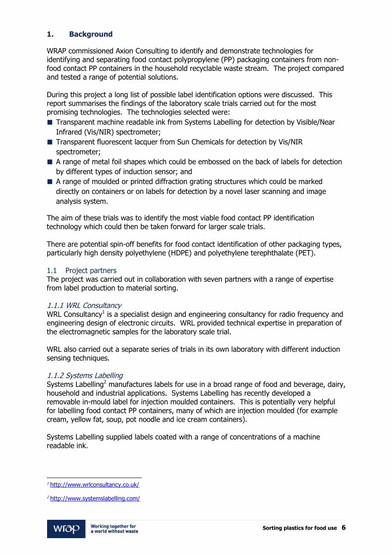
List of figures
Figure 1 Sun Chemical test samples mounted on PP sheet ............................................. 14 Figure 2 TITECH Polysort NIR frequency sensor ............................................................ 15 Figure 3 A label sample prepared by Systems Labelling with machine readable ink lacquer 16 Figure 4 Reflectance spectrum for machine readable labels in the near infra-red range from laboratory spectrometer ................................................................................................ 16 Figure 5 Pellenc machine readable label test arrangement.............................................. 17 Figure 6 Diffraction from a plane grating ...................................................................... 20 Figure 7 Moulding insert design for diffraction trials ....................................................... 21 Figure 8 Button mould insert ....................................................................................... 21 Figure 9 Diamond engraved mould insert 200 lines/mm – magnification x 5,000 .............. 22 Figure 10 Diamond engraved mould insert 100 lines/mm – magnification x 4,000 ............ 22 Figure 11 Diamond engraved mould insert 30 lines/mm – magnification x 1,500 .............. 22 Figure 12 Battenfield microsystem 50 injection moulder, University of Bradford ............... 23 Figure 13 Injection mould in position in moulding machine ............................................ 23 Figure 14 Range of samples from clear to white ............................................................ 24
Sorting plastics for food use 4
Figure 15 „Clear‟ PP injection moulded diffraction grating sample .................................... 24 Figure 16 Experiment setup ......................................................................................... 25 Figure 17 Clear sample, centre grating 200 lines/mm .................................................... 26 Figure 18 Improved 1 micron infra-red diffraction grating test rig ................................... 28 Figure 19 Diffraction pattern observed with 30 lines/mm grating and 1 micron infra-red laser ............................................................................................................................ 28 Figure 20 Diffraction pattern observed with 100 lines/mm grating and 1 micron infra-red laser ............................................................................................................................ 29 Figure 21 Impression moulding rig for diffraction gratings at University of Bradford ......... 29 Figure 22 Impression moulded PP sheet samples .......................................................... 31 Figure 23 SEM image of 200 lines/mm grating, impression moulded at 140°C (magnified x 5000) .......................................................................................................................... 31 Figure 24 SEM image of 100 lines/mm grating, impression moulded at 150C (magnified x 3000) .......................................................................................................................... 32 Figure 25 SEM image of 30 lines/mm grating, impression moulded at 150C (magnified x 800) ............................................................................................................................ 32 Figure 26 Initial test with red laser pointer on impression moulded strip.......................... 33 Figure 27 Grating impression moulded in PP ice cream tub lid ........................................ 33 Figure 28 Grating impression moulded in PP child‟s food pot .......................................... 34 Figure 29 Diffraction pattern from the 30 lines/mm grating ............................................ 34 Figure 30 Diffraction pattern from the 100 lines/mm grating .......................................... 35 Figure 31 Diffraction pattern from the 200 lines/mm grating .......................................... 35 Figure 32 Diffraction pattern from the 30 lines/mm grating with the laser incident on the „back‟ of the sample ...................................................................................................... 36 Figure 33 Diffraction pattern from the 100 lines/mm grating with the laser incident on the „back‟ of the sample ...................................................................................................... 36 Figure 34 Diffraction pattern from the 200 lines/mm grating with the laser incident on the „back‟ of the sample ...................................................................................................... 37 Figure 35 Diffraction pattern from the front surface of the 30 lines/mm grating in the PP ice cream tub lid ............................................................................................................... 37 Figure 36 Diffraction pattern from the front surface of the 100 lines/mm grating in the PP ice cream tub lid .......................................................................................................... 38 Figure 37 Diffraction pattern from the front surface of the 200 lines/mm grating in the PP ice cream tub lid .......................................................................................................... 38 Figure 38 Self-adhesive label structure ......................................................................... 40 Figure 39 Example of self-adhesive label design ............................................................ 41 Figure 40 Self-adhesive printed label samples from Systems Labelling ............................ 41 Figure 41 In-mould label structure ............................................................................... 42 Figure 42 Grating in ink on self-adhesive label - Magenta lines with no ink in between 10 lines/mm ..................................................................................................................... 43 Figure 43 Grating in ink on self-adhesive label - Magenta lines with no ink in between 25 lines/mm ..................................................................................................................... 44 Figure 44 Grating in ink on self-adhesive label - Black lines with no ink in between 10 lines/mm ..................................................................................................................... 44 Figure 45 Grating in ink on in-mould label - Magenta lines with no ink in between, 10 lines/mm ..................................................................................................................... 45 Figure 46 Grating in ink on in-mould label - Black lines with no ink in between, 10 lines/mm .................................................................................................................................. 46 Figure 47 Cross section showing – sample facing away from the EM3 sensor ................... 49 Figure 48 Foil test samples prepared for induction sorting trials at TITECH ...................... 50 Figure 49 Combined NIR and induction sensing test machine at TITECH test facility ........ 50 Figure 50 Image from TITECH induction sensing system of 0.75 micron foil samples passing over the induction sensor .............................................................................................. 51 Figure 51 Simulated rectifier label (right) and ferromagnetic label (left) .......................... 54

Sorting plastics for food use 5
Figure 52 Detection coils ............................................................................................. 55 Figure 53 Traces from the spectrum analyser for harmonic generation with the simulated rectifier label ................................................................................................................ 56 Figure 54 Three oscilloscope traces for excitation and detection coils .............................. 57
Acknowledgements
WRAP and Axion Consulting would like to thank the following companies and organisations for their time and support in delivering this project:
Sun Chemicals;
Systems Labelling;
Pellenc Selective Technologies;
Pragmatic Printing;
TITECH;
University of Bradford;
University of Durham; and
WRL Consulting.
Sorting plastics for food use 6
1. Background
WRAP commissioned Axion Consulting to identify and demonstrate technologies for identifying and separating food contact polypropylene (PP) packaging containers from non-food contact PP containers in the household recyclable waste stream. The project compared and tested a range of potential solutions. During this project a long list of possible label identification options were discussed. This report summarises the findings of the laboratory scale trials carried out for the most promising technologies. The technologies selected were:
Transparent machine readable ink from Systems Labelling for detection by Visible/Near
Infrared (Vis/NIR) spectrometer;
Transparent fluorescent lacquer from Sun Chemicals for detection by Vis/NIR
spectrometer;
A range of metal foil shapes which could be embossed on the back of labels for detection
by different types of induction sensor; and
A range of moulded or printed diffraction grating structures which could be marked
directly on containers or on labels for detection by a novel laser scanning and image
analysis system.
The aim of these trials was to identify the most viable food contact PP identification technology which could then be taken forward for larger scale trials. There are potential spin-off benefits for food contact identification of other packaging types, particularly high density polyethylene (HDPE) and polyethylene terephthalate (PET). 1.1 Project partners The project was carried out in collaboration with seven partners with a range of expertise from label production to material sorting. 1.1.1 WRL Consultancy WRL Consultancy1 is a specialist design and engineering consultancy for radio frequency and engineering design of electronic circuits. WRL provided technical expertise in preparation of the electromagnetic samples for the laboratory scale trial.
WRL also carried out a separate series of trials in its own laboratory with different induction sensing techniques. 1.1.2 Systems Labelling Systems Labelling2 manufactures labels for use in a broad range of food and beverage, dairy, household and industrial applications. Systems Labelling has recently developed a removable in-mould label for injection moulded containers. This is potentially very helpful for labelling food contact PP containers, many of which are injection moulded (for example cream, yellow fat, soup, pot noodle and ice cream containers). Systems Labelling supplied labels coated with a range of concentrations of a machine readable ink.
1 http://www.wrlconsultancy.co.uk/
2 http://www.systemslabelling.com/

Sorting plastics for food use 7
1.1.3 Sun Chemical Sun Chemical3 is a large ink and pigment manufacturer. Sun Chemical supplied blank labels coated with a clear fluorescent lacquer in a range of concentrations for the trials at TITECH. 1.1.4 TITECH TITECH4 is a supplier of automated waste sorting equipment. The company is active in R&D and develops a wide range of technologies for the sorting of recyclables. TITECH provided equipment and expertise for testing the sample labels at its R&D site Mulheim Karlich in Germany. 1.1.5 Pellenc Selective Technologies Pellenc Selective Technologies5, based at Pertuis in France is a supplier of automatic sorting equipment for household and industrial waste materials. These materials are sorted using a variety of technologies including artificial vision and multi-spectral image analysis. Pellenc tested sample labels at its R&D facility in Pertuis. 1.1.6 University of Bradford School of Engineering Design and Technology The Department of Polymer Micro and Nano Technology6 within the School of Engineering, Design and Technology at the University of Bradford is a centre of excellence for advanced polymer processing. Professor Phil Coates and Dr Ben Whiteside lead the group that conducted the injection moulding and impression moulding trials of diffraction grating structures for the project. 1.1.7 University of Durham The diamond engraved button mould inserts for the diffraction grating tests were manufactured for Bradford University by the Precision Optics Laboratory of Durham University‟s Centre for Advanced Instrumentation7 led by Professor David Robertson.
3 http://www.sunchemical.com/
4 http://www.titech.com/
5 www.pellencst.com
6 www.polymer-mnt.brad.ac.uk
7 www.durhamprecisionoptics.co.uk
Sorting plastics for food use 8
2. Why develop a food contact packaging marker?
European Food Safety Authority (EFSA) guidelines published by the International Life Sciences Institute8 require that over 99% of the feed material for a recycling process making food grade recycled polymer must have previously been used in contact with food. This has recently been relaxed to 95% for PET recycling processes but not for recycling processes for other polymer types. These guideline limits have been proposed based on practical experience. It is difficult to ensure that non-food approved substances that are absorbed into the polymer during the use phase of the packaging are fully eliminated during the recycling process, unless the percentage of non-food contact plastic in the feed material is below 1% for most polymer types, including PP, and below 5% for PET.
There is increasing demand from retailers and brand owners (in response to consumer pressure) to increase recycled content in all packaging types and by this means to reduce the carbon impact of their products. Recent work for WRAP9 indicates that total rigid PP in the household waste stream is about 180,000t/yr. The same report estimates that 50-70% of the rigid PP in the household packaging waste stream is food contact and therefore potentially suitable as feedstock for food grade recycling. This creates a potential raw material supply of up to about 125,000t/yr for food grade recycling processes. Automated near infra-red sorting technology is widely adopted in the recycling sector to separate PP packaging from other polymer types and baled rigid PP packaging from household waste is already a traded commodity. At present no separation techniques are available to sort food contact from non-food contact packaging. It is not commercially viable to hand sort to remove the 30-50% of non-food contact PP from rigid PP packaging. This creates a barrier to the development of food grade PP recycling capacity in the UK market. The focus of this project was to develop and test marking and sorting methods which could potentially be developed further into a commercially viable automated separation system for food contact PP packaging. There is an increasing amount of non-food contact packaging in the natural HDPE and PET waste packaging streams. At present recyclers use hand sorting to remove the non-food contact material in these streams but this is becoming increasingly expensive. If these trends continue the development work for this project may also have spin-off benefits for food grade recycling of PET and HDPE in future.
2.1 Attributes for a food contact marker At the start of the project the attributes that are required from a food contact marking system for PP packaging were discussed with packaging and label manufacturers, recycling plant operators and sorting machine builders. Any food contact marker system should conform to the following criteria:
Identifiable at commercial sorting speed – sorting machines used in the recycling
sector run with belt speeds between 2-3 metres per second and the detector is usually
8 ILSI, “Recycling of plastics for food contact use”, ILSI report series (Belgium: ILSI Press, 1998) http://www.ilsi.org/Europe/Publications/R1998Rec_Plas.pdf
9 „UK market composition data of polypropylene packaging‟, Axion Consulting for WRAP March 2012

Sorting plastics for food use 9
positioned only about 30cm from the air jets which eject the target material so items
must be identified within about 50 milliseconds;
Visible from all sides of the container – containers may be presented to the sorting
machine in any orientation so the food contact marking should be visible to the sensing
system from any side of the container. Many PP packaging items are rectangular trays or
cartons so they may easily present the inside face of the package to the sensor;
Robust – waste packaging may be crushed several times through the collection and
recycling process – in the household, in the rotary compactor collection vehicle and in
balers at the recycling plant. The marking must still be readable after crushing;
Marker data destroyed or removed in the recycling process – it is essential that
the food contact marking is eliminated from the material during the recycling process. If
not, a food contact item may pass through a non-food grade recycling process and be
made into a non-food contact packaging item such as a detergent bottle, which might
then be incorrectly identified as food contact on its next trip round the recycling loop;
Must not interfere with branding – branding of retail food packaging is really
important for the retailer, brand owner and consumer. Packaging labels in the UK already
carry a great deal of product information, including dietary data and recycling guidance.
These reduce the space available for brand communication. Packaging designers are
therefore very reluctant to agree to release additional label space for food contact
identification; and
Very low cost – although they are often quite complex multi-layer structures with up to
eight colours of printing food packaging labels are extremely low cost, typically less than
0.75p per label. Even at this price they are a significant component of the whole
packaging item cost so any marking system that increases cost would have to be
considered very seriously by packaging makers before it was introduced.
Sorting plastics for food use 10
3. Marker options considered
At the start of the project a long list of possible marking options were considered. These fell into three main categories: polymer additives, removable labels and surface markings. 3.1 Polymer additives Additives included in the polymer prior to moulding are simple to use from the point of view of the packaging manufacturer, many of them are relatively low cost at the concentrations required and it should be relatively straightforward to detect them using standard spectroscopic sorting techniques. Additives are present throughout the polymer and are therefore visible from any side of the packaging item. Three particular types of additive were considered in some detail:
Nano metal particles – tiny particles of gold or silver are potentially detectable by
spectroscopic techniques and, depending on the sensitivity of the detection technique,
could potentially be added at low enough concentrations to be commercially viable;
Quantum dots – these are tiny chemical particles which are being used increasingly in
security and medical diagnostic applications. They emit a characteristic light „signature‟
when illuminated. Again they should be detectable by spectroscopic techniques. They
are relatively expensive and many have toxicity issues, which would make them
unsuitable for food applications; and
Dyes – there are several types of polymer dye which could potentially be invisible to the
human eye but would create a characteristic optical „signature‟ in the infra-red or ultra
violet range for detection by spectroscopic sorters.
A fundamental disadvantage of all polymer additives for food contact marking is that they must be thermally stable to resist degradation in the moulding process. Because they are thermally stable they will maintain their marking ability after the recycling process, whether they return in their next product life as a food contact or non-food contact item of packaging. On this basis all types of polymer additives were eliminated from the short list of possible techniques to be trialled. 3.2 Labels Three main types of label are used in PP packaging:
Direct printed - mostly for thermoformed packages;
Self-adhesive - for all packaging types but mostly thermoformed and blow-moulded; and
In-mould labelled - for injection moulded items.
At present only self-adhesive labels are capable of being physically removed in current recycling processes. The ease of removal depends to some extent on the type of adhesive used. Self-adhesive labels also create an additional waste stream for the recycler because the label material tends to hold water and there are usually only limited outlets for it. Removable in-mould labels are currently being marketed by certain label suppliers including Systems Labelling and there is potential to improve the removability and recyclability of self-adhesive labels further by adjusting their construction materials and adhesive types. Direct print labels and non-removable in-mould labels are destroyed when the package is recycled because they are mixed in with the packaging polymer. The ink in the labels colours the polymer, making it suitable for use only in darker coloured applications. There is still some uncertainty over whether the ink materials create any food grade certification issues. Recent migration tests carried out for WRAP10 on recycled food contact PP indicate 10 Phase 3 Food Grade rPP decontamination final report
Sorting plastics for food use 11
that no inks or ink degradation products from direct print or in-mould labels were detected so this may not be a serious issue. However further work is likely to be required to convince regulators of this. In summary therefore, labels are potentially an attractive choice for PP food contact marking because they can either be removed or destroyed in the recycling process. They tend to be relatively low cost and they are usually added to packaging close to the time of use so there is little scope for non-food contact packages to be mis-identified as food contact. One potential disadvantage of many label types for food contact identification is that they are fixed only to the outside of the container. This is not a problem for bottles, pots and jars because the label can be designed to wrap round the whole package. However it is an issue for flat and rectangular items such as margarine cartons and meat trays where it is possible that only the inside of the container can be „seen‟ by the automatic sorter. A further issue with marking labels rather than the package itself is that they may come off the package prior to reaching the processor, either because they are removed by the householder or while the label is in transit through the waste collection system. Several types of label were considered at the long-list stage of the project:
Readable symbols, identifiable by image analysis – machine vision systems are
becoming increasingly sophisticated and could potentially detect particular symbols or
patterns printed on the label. This type of label would be very low cost and it should be
relatively easy to develop the detection technology. This idea was eliminated from the
short list as they would use too much space on the label, interfering with branding, and
may not be visible from all sides of the package;
Machine readable inks, identifiable by spectrometry - a clear lacquer printed on
the surface of the label which is detectable by a standard recycling sensor based sorter in
the infra-red or ultra violet range is an attractive solution. It does not interfere with
branding in any way but covers the whole label surface and therefore has a high
probability of being presented to the sorter. If the package is made of clear polymer and
the rear of the label is also coated then the ink could be detectable from the inside of the
container as well. Near infra-red and visible light optical sorters are widely used already
in recycling of packaging. Two options were added to the short list and tested in this
project. These were an ultra violet fluorescent pigment from Sun Chemical and a
machine readable ink supplied by Systems Labelling;
Metal foil structures, identifiable by induction sensor – induction sensor sorters
are widely used in recycling of metals and are supplied by the same companies that make
the optical sorters that are used in recycling of packaging. The principal advantage of
metal structures is that they can be detected from any side of the container; they do not
have to be in the line of sight of the detector. Foil is already used to decorate both food
and non-food contact labels so technology is available to apply foil at reasonable cost.
Disadvantages of metal structures are that many food manufacturers exclude all metal
from their plastic packaging so that they can use metal detectors to detect contamination.
The fact that foil decoration is already used on non-food packaging is also a disadvantage
for the simpler induction sensing methods. Three induction sensing options were added
to the short list and tested in this project. These were foil shapes, low cost printed
electrical circuits or multi-layer strips that generate harmonics and ferrite strips that
generate a phase shift;
Holographic images – holograms are widely used in security marking and can be
designed to be readily identifiable by automated image analysis systems. They do use up

Sorting plastics for food use 12
space on the label but can potentially be made small enough that they should not be too
obtrusive. Discussions were held with several holographic label suppliers. It was
concluded that they would always be too expensive for use on high volume food
packaging so they were eliminated from the short list; and
Radio Frequency Identification (RFID) tags – RFID tags are used in many security
and identification applications for higher value items. Although they are mass produced,
discussions with suppliers indicated that they would always be too expensive for food
grade identification so they were eliminated from the short list.
3.3 Surface markings in package moulding or on a label If a food contact identification mark could be moulded into the structure of the packaging this would have several advantages. The marking information would be destroyed as soon as the polymer was melted in the recycling process. The moulding would not use valuable information space on the label and it could be applied to unlabelled items. A moulded mark can potentially be marked on both the inside and outside surfaces of the package, or for clear polymer items it is visible from both sides. Most methods of moulding markings are very low cost as they use the packaging material itself. A further advantage of moulded markings is that many PP packaging items are not labelled at all because label information is included on a cardboard sleeve or a peel off foil lid. It is also potentially feasible to emboss or mould unobtrusive or invisible surface markings on labels which can be applied to the package after moulding. Two moulded marking systems were considered for the long list:
Readable moulded or embossed symbols – it is potentially feasible to mould or
emboss a standard food contact symbol into the surface of the package or the label while
still maintaining the readability of the label and branding information. The length scale of
this symbol would need to be of the order of minimum 10mm to be readable by image
recognition systems at sorting speed and it would need to be repeated across the surface
of the object so that it is visible from all sides. If the object is illuminated at an oblique
angle in order to create contrast by means of shadows it should be possible to identify
food contact items at reasonable speed. This idea was excluded from the short list
because of concerns over reliability of detection and the visual and marketing impact of
moulded food contact symbols of 10mm+ scale across the surface of food packaging
items; and
Diffraction gratings – a proof of concept study for WRAP during late 201111
demonstrated that it is feasible to injection mould diffraction gratings in PP in a way that
would create low impact on the packaging appearance and that could generate reflected
diffraction patterns that are potentially readable at high speed by image analysis systems.
A further potential advantage of diffraction grating markings is that the diffraction grating
can go on either the pack itself or on the label, offering more flexibility to packaging
designers. This idea was added to the short list for this project.
11 „Diffraction Grating -Proof of Concept Final Report‟, WRAP project PCF001, Axion Consulting, February 2012

Sorting plastics for food use 13
4. Short listed PP food contact marker options
Three main marker options were therefore short-listed for practical trials in this project as follows:
Machine readable inks – two types:
o Sun Chemical Fluorescent pigment;
o Systems Labelling machine readable ink.
Induction sensing – three types:
o Aluminium foil shapes with conventional sensors;
o Printable circuits and materials that create harmonics; and
o Materials that create a phase shift.
Diffraction gratings – three types:
o Injection moulded;
o Impression moulded; and
o Printed structures.

Sorting plastics for food use 14
5. Lacquered labels
Two different machine readable inks that are transparent in the visible range and can therefore be used to cover the full label surface without obscuring label and brand information were tested in the project. Both are already used in security marking applications and are low enough in cost to be commercially viable for use on mass-market food labels. The suppliers of both pigments provide hand-held reader units which detect the ink very reliably when placed directly on the lacquered material. The challenge for recycling applications is to find a material which is detectable by the type of automatic optical sorting machines that are used for bulk separation of waste plastics. On recycling machines the detectors are typically positioned 500-1000mm away from the surface of the sorting belt. This separation is required by the geometry of the scanning systems used by the detectors. In order to cover a wide sorting belt while retaining accurate position measurement capability the scanning detector must be positioned some distance away from the sorting belt. 5.1 Fluorescent pigmented lacquer– Sun Chemical The pigment supplied by Sun Chemical for testing is fluorescent. When it is illuminated with ultra violet light it absorbs the light and re-emits a characteristic spectrum at longer wavelengths in the visible range between 400 and 900nm. The readers supplied by Sun Chemical detect the absorption of ultra violet light and the characteristic emission peaks in the visible range. Test pieces were made for trial at TITECH‟s test facility at Mulheim-Karlich in Germany. Samples of thin PP film coated with lacquer were made up by Sun Chemical with a range of pigment loadings. The film simulated the top layer of a typical self-adhesive label structure. The samples were mounted on pieces of pigmented and transparent PP sheet in order to simulate labels on white and clear PP containers, as can be seen in Figure 1.
Figure 1 Sun Chemical test samples mounted on PP sheet

Sorting plastics for food use 15
A modified TITECH Polysort sensor based sorting machine was used for the trials. The machine included an induction metal sensor in addition to the standard NIR unit. The machine was not fitted with ejection nozzles because it was used only to test the detection capability of the sensors. The NIR sensor unit is shown in Figure 2.
Figure 2 TITECH Polysort NIR frequency sensor
The NIR sensor detects the spectrum of light in the near-infra red spectral range. A second sensor unit on a different test machine was used to check the response in the visible spectral range. Despite several attempts with a range of settings it was not possible to detect a characteristic spectrum from the Sun Chemical samples. This is because the intensity of the fluorescence response of the pigment was too low to be detectable by the sorting spectrometer due to the distance from the sorting belt and with the level of background illumination required for standard sorting technology. After the trials Sun Chemical demonstrated its own detection technology which can work up to distances of 30-200mm from the sample. However it was decided to abandon further development of this pigment system on the basis that 30-200mm is too close for practical sorting in a recycling environment. 5.2 Machine readable lacquer – Systems Labelling Several sets of label samples were prepared by Systems Labelling for the trials. Both in-mould and self-adhesive label types were produced; each with a range of machine readable ink loadings in the lacquer. Some of the samples were mounted on clear PP sheet and some on white PP sheet. The sample set included control samples with no machine readable ink in the lacquer layer. Figure 3 shows an example of a label sample prepared by Systems Labelling.

Sorting plastics for food use 16
Figure 3 A label sample prepared by Systems Labelling with machine readable ink lacquer
orescent la
Initially TITECH tested the reflectance of the samples in the near infra-red range with a laboratory spectrometer. The marked samples for two label types (milk label and juice label) were compared against a highly reflective barium sulphate (BaSO4) reference sample, a PET plastic bottle and an un-pigmented label. See Figure 4 for the reflectance spectrum generated.
Figure 4 Reflectance spectrum for machine readable labels in the near infra-red range from laboratory spectrometer
This test showed a significant reduction in reflectance for the marked samples in a 100nm wavelength range in the near infra-red spectrum. This was unexpected as the observed wavelengths were not those at which the coating was expected to absorb. However NIR
Sorting plastics for food use 17
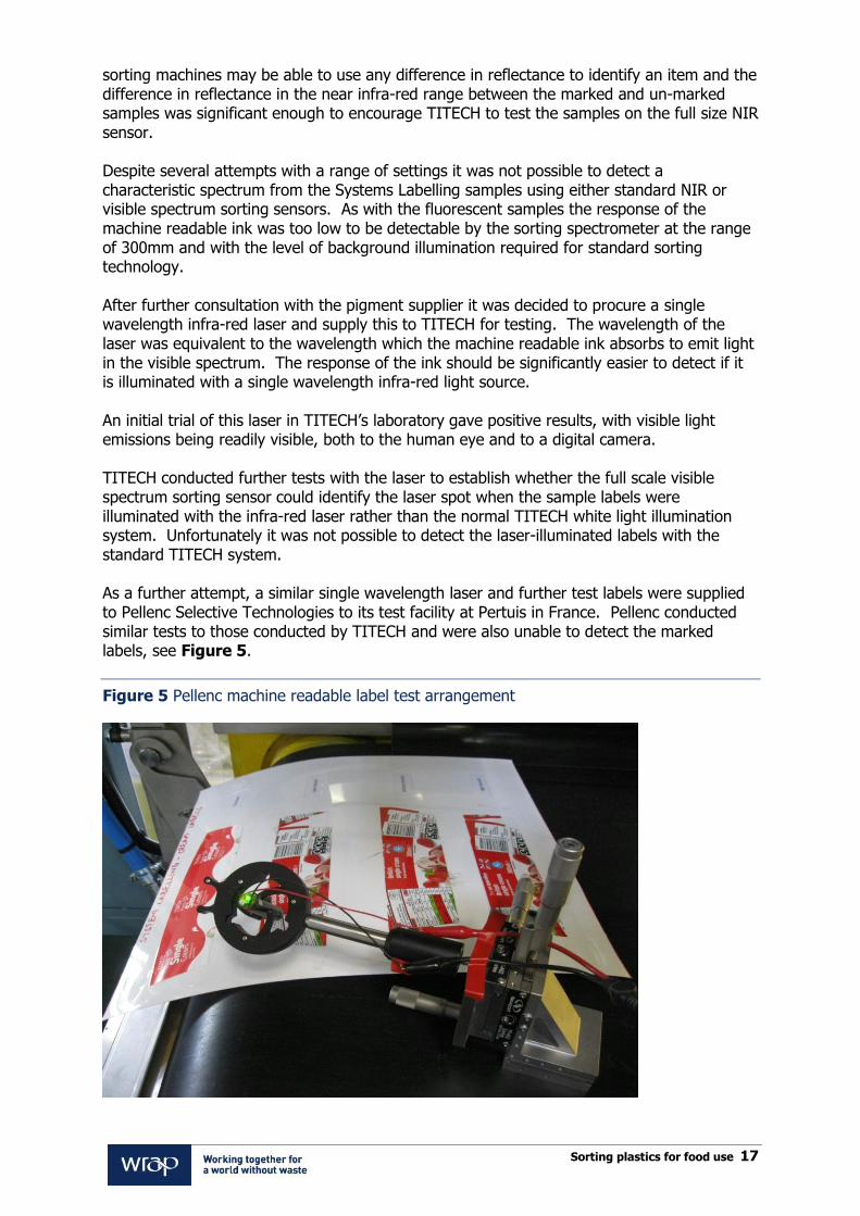
sorting machines may be able to use any difference in reflectance to identify an item and the difference in reflectance in the near infra-red range between the marked and un-marked samples was significant enough to encourage TITECH to test the samples on the full size NIR sensor. Despite several attempts with a range of settings it was not possible to detect a characteristic spectrum from the Systems Labelling samples using either standard NIR or visible spectrum sorting sensors. As with the fluorescent samples the response of the machine readable ink was too low to be detectable by the sorting spectrometer at the range of 300mm and with the level of background illumination required for standard sorting technology. After further consultation with the pigment supplier it was decided to procure a single wavelength infra-red laser and supply this to TITECH for testing. The wavelength of the laser was equivalent to the wavelength which the machine readable ink absorbs to emit light in the visible spectrum. The response of the ink should be significantly easier to detect if it is illuminated with a single wavelength infra-red light source. An initial trial of this laser in TITECH‟s laboratory gave positive results, with visible light emissions being readily visible, both to the human eye and to a digital camera. TITECH conducted further tests with the laser to establish whether the full scale visible spectrum sorting sensor could identify the laser spot when the sample labels were illuminated with the infra-red laser rather than the normal TITECH white light illumination system. Unfortunately it was not possible to detect the laser-illuminated labels with the standard TITECH system. As a further attempt, a similar single wavelength laser and further test labels were supplied to Pellenc Selective Technologies to its test facility at Pertuis in France. Pellenc conducted similar tests to those conducted by TITECH and were also unable to detect the marked labels, see Figure 5.
Figure 5 Pellenc machine readable label test arrangement

Sorting plastics for food use 18
The machine readable ink or fluorescent pigmented label option is still attractive from a commercial and practical point of view if a sensing method can be developed. The machine readable inks are relatively low cost and they can be made to cover a large area of the container and therefore have good potential for detection and they do not interfere with branding because they are invisible. There is potential to develop a sensing solution for the machine readable ink using a line scan colour camera and a scanning infra-red laser that is synchronised with the camera. It is likely that the sensing area would have to be totally enclosed to prevent other light sources from reducing the signal-to-noise ratio of the sensors. Sensing systems of this type would require some development by the sorting machine makers but most of the elements of the system have already been trialled by the sorting machine makers for other applications. This development would be relatively easy to retrofit to optical sorting machines of the type already widely used in sorting of packaging. It is possible that the fluorescent pigment could also be developed further in the same way using an ultra-violet light source.

Sorting plastics for food use 19
6. Induction sensing marker options
The advantages and disadvantages of induction sensing solutions have already been discussed in Section 3. The main advantages are that the marker can be applied to the rear of the label and will therefore not interfere with branding and is detectable whichever orientation the package is presented to the sorting machine. Three induction sensing techniques were tested in this project:
Aluminium foil shapes;
Printable circuits and materials that create harmonics; and
Materials that create a phase shift.
The first of these are detectable by conventional induction sorting machines as used in recycling of metals. This type of marker could therefore by introduced relatively easily by retrofitting existing NIR sorting machines with the current type of induction sensor or adding new conventional induction sorters to existing sorting plants. The other two induction sensing techniques are widely used in other sectors such as airport, retail and library security but would require development of new sensors and analysis software by the recycling sorting machine makers. A strong market demand for food contact identification would need to be demonstrated in order to persuade the sorting machine makers to undertake this development. The results of these trials are summarised in Appendix A and not discussed in detail here. This is because, although two of the three techniques (circuits and materials that create harmonics and materials that create a phase shift) worked well and are potentially detectable with packages in any orientation, the cost and complexity of developing these techniques to the point where they could be used in mass market packaging is likely to be significantly greater than the other marking methods trialled in this project. As a result it is recommended that these techniques should not be taken further beyond the current proof of concept stage.

Sorting plastics for food use 20
7. Diffraction gratings
The initial proof of concept work for the use of diffraction gratings as a method for food contact identification and sorting has already been described in a separate WRAP report12. This work is summarised below. 7.1 Initial proof of concept work on diffraction gratings Diffraction gratings are structures created within or on a surface which comprise regularly spaced lines or grids. When they are illuminated with laser light of an appropriate wavelength they create interference patterns in the laser light which are visible as regularly spaced spots or lines with a frequency which is characteristic of the frequency of the laser light and the spacing of the lines in the diffraction grating. Figure 6 shows diffraction from a plane grating.
Figure 6 Diffraction from a plane grating
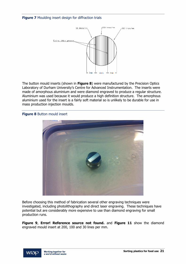
To create a good quality diffraction pattern with visible or infra-red laser light, the spacing of the lines must be somewhere in the range 30-200 lines/mm. This is a very fine structure which does not create a major impact on the appearance of the packaging and should therefore be attractive to retailers, pack designers and brand owners as a marking system to indicate food contact. In the initial project injection moulded PP samples were made to simulate the type of gratings which could potentially be moulded into the surface of injection moulded PP packaging items such as margarine tubs and dairy pots. Figure 7 shows the moulding insert design used for the initial investigations. These samples were then tested by Axion using a 650nm wavelength red laser pointer.
12 WRAP project PCF001, „Laser diffraction for waste identification and sorting‟, Axion Consulting, March 2012
d
Incident beam of light
Diffracted
light beams
Sorting plastics for food use 21
Figure 7 Moulding insert design for diffraction trials
The button mould inserts (shown in Figure 8) were manufactured by the Precision Optics Laboratory of Durham University‟s Centre for Advanced Instrumentation. The inserts were made of amorphous aluminium and were diamond engraved to produce a regular structure. Aluminium was used because it would produce a high definition structure. The amorphous aluminium used for the insert is a fairly soft material so is unlikely to be durable for use in mass production injection moulds.
Figure 8 Button mould insert
Before choosing this method of fabrication several other engraving techniques were investigated, including photolithography and direct laser engraving. These techniques have potential but are considerably more expensive to use than diamond engraving for small production runs. Figure 9, Error! Reference source not found. and Figure 11 show the diamond engraved mould insert at 200, 100 and 30 lines per mm.

Sorting plastics for food use 22
Figure 9 Diamond engraved mould insert 200 lines/mm – magnification x 5,000
Figure 10 Diamond engraved mould insert 100 lines/mm – magnification x 4,000
Figure 11 Diamond engraved mould insert 30 lines/mm – magnification x 1,500
The sample injection mouldings were produced at the University of Bradford IRC Polymer Process Engineering Centre, Micro and Nano Technology laboratory. A Battenfield microsystem 50 injection moulder was used to produce the sample mouldings, shown in Figure 12.

Sorting plastics for food use 23
Figure 12 Battenfield microsystem 50 injection moulder, University of Bradford
Figure 13 shows the moulding machine with the injection mould in position.
Figure 13 Injection mould in position in moulding machine
For the process, the mould temperature was set at 60°C whilst the processing temperature varied between 220-230°C; this was controlled automatically. A small amount of white masterbatch was mixed with clear PP granules to produce white coloured PP mouldings initially, which changed to clear mouldings as the portion containing white pigment passed through the machine. A total of 260 samples were produced ranging from white to clear. Figure 14 shows the range of samples produced.
Metering
device
Injection
piston
Cavity
Cylinder containing
PP granules
Sorting plastics for food use 24
Figure 14 Range of samples from clear to white
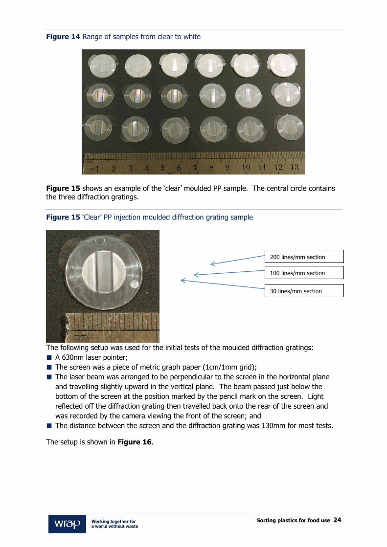
Figure 15 shows an example of the „clear‟ moulded PP sample. The central circle contains the three diffraction gratings.
Figure 15 „Clear‟ PP injection moulded diffraction grating sample
The following setup was used for the initial tests of the moulded diffraction gratings:
A 630nm laser pointer;
The screen was a piece of metric graph paper (1cm/1mm grid);
The laser beam was arranged to be perpendicular to the screen in the horizontal plane
and travelling slightly upward in the vertical plane. The beam passed just below the
bottom of the screen at the position marked by the pencil mark on the screen. Light
reflected off the diffraction grating then travelled back onto the rear of the screen and
was recorded by the camera viewing the front of the screen; and
The distance between the screen and the diffraction grating was 130mm for most tests.
The setup is shown in Figure 16.
200 lines/mm section
100 lines/mm section
30 lines/mm section

Sorting plastics for food use 25
Figure 16 Experiment setup
Figure 17 shows the results obtained for a clear plastic sample, with the central grating of 200 lines/mm being tested.
Camera
Laser Pointer
Diffraction
Grating
Screen

Sorting plastics for food use 26
Figure 17 Clear sample, centre grating 200 lines/mm
The tests demonstrated that good quality, easily readable, diffraction patterns could be generated from both white and clear test pieces from diffraction gratings with periods of 100 and 200 lines/mm. There were indications that with an improved optical set-up and a longer wavelength infra-red laser source it should be possible to create detectable patterns with acceptable signal to noise ratio from a grating with a period of 30 lines/mm. This would be considerably easier to mould than a 100 line/mm grating. Discussions were held with two suppliers of laser-based recycling sorting machinery; Visys Global13 and Best Sorting14. Both companies are located in Belgium. Both Visys Global and Best Sorting indicated that in principle it should be possible to build a sorting machine that uses the laser diffraction technique to identify food contact packaging at commercially viable speeds. The diffraction patterns would be detected by digital camera technology and analysed by calculating Fourier transforms of the resulting images. The frequency of the diffraction patterns would generate a characteristic peak in the Fourier transform plot which would indicate food contact material. To detect the diffracted pattern, a screen is positioned a distance from the transparent wall of the chute. The diffracted beams hit the screen and form spots on the screen which can be photographed using a camera. A camera cannot directly record the diffractive beams
13 www.visysglobal.com
14 www.bestsorting.com
Graph paper
screen
10mm
Pencil mark – laser beam
passes just below this
mark
Line of spots due to the
diffracted beams
Sample
Sorting plastics for food use 27
because the camera lens will be small in comparison to the width of the chute and the diffracted beams will most likely miss the lens. The chute is assumed to be approximately 300mm wide to allow for large plastic packaging items. The laser beam from the scanner will need to hit the plastic packaging behind the viewing screen. This could be achieved by directing the laser upward at an angle so that it hits the packaging behind the screen and the diffracted pattern reflects upward onto the back of the screen. Image processing will be required to isolate a diffraction pattern from the images recorded by the camera. This is because the packaging, and therefore the diffraction patterns, will be presented at a wide variety of angles, both in the plane of the transparent wall of the chute and out of this plane. Undoubtedly there are many different possible geometries and many issues to further overcome before a sorting machine design could be finalised.
7.2 Further diffraction grating development conducted for this project The success of the proof of concept work described in Section 7.1 prompted WRAP to request further development of the idea. 7.2.1 Longer wavelength laser to improve diffraction pattern definition with coarser grating
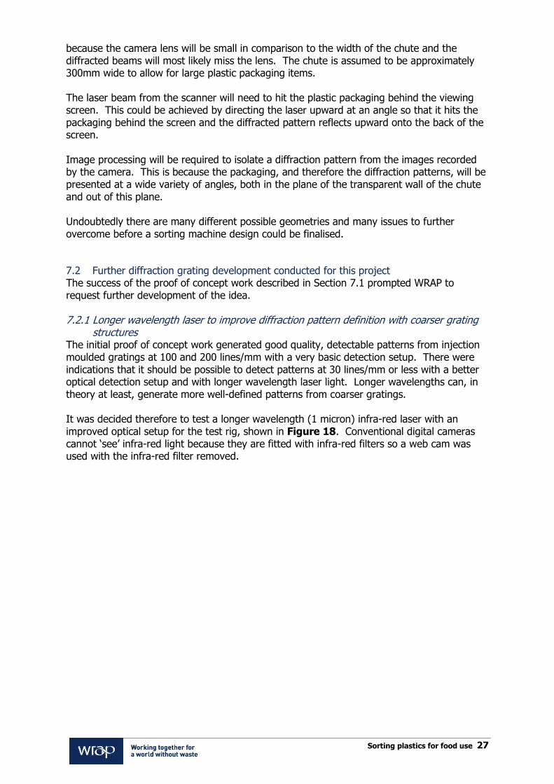
structures The initial proof of concept work generated good quality, detectable patterns from injection moulded gratings at 100 and 200 lines/mm with a very basic detection setup. There were indications that it should be possible to detect patterns at 30 lines/mm or less with a better optical detection setup and with longer wavelength laser light. Longer wavelengths can, in theory at least, generate more well-defined patterns from coarser gratings. It was decided therefore to test a longer wavelength (1 micron) infra-red laser with an improved optical setup for the test rig, shown in Figure 18. Conventional digital cameras cannot „see‟ infra-red light because they are fitted with infra-red filters so a web cam was used with the infra-red filter removed.
Sorting plastics for food use 28
Figure 18 Improved 1 micron infra-red diffraction grating test rig
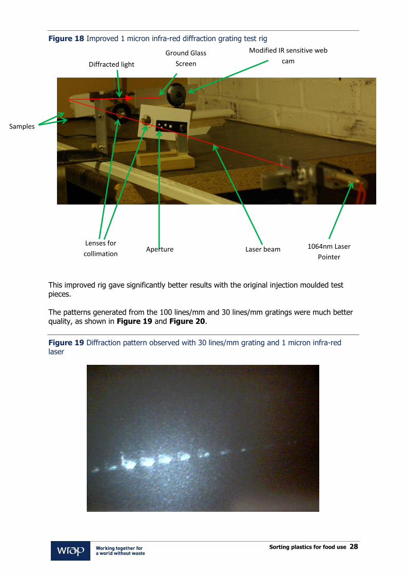
This improved rig gave significantly better results with the original injection moulded test pieces. The patterns generated from the 100 lines/mm and 30 lines/mm gratings were much better quality, as shown in Figure 19 and Figure 20.
Figure 19 Diffraction pattern observed with 30 lines/mm grating and 1 micron infra-red laser
Ground Glass
Screen
Samples
1064nm Laser
Pointer
Modified IR sensitive web
cam
Aperture Lenses for
collimation
Diffracted light
Laser beam

Sorting plastics for food use 29
Figure 20 Diffraction pattern observed with 100 lines/mm grating and 1 micron infra-red laser
7.2.2 Alternative grating options A second concern regarding the initial work was the practicality of moulding such fine structures in the surface of mass market packaging items. Patterns at 100 and 200 lines/mm can be injection moulded with reasonable definition but the mould insert may be worn away more easily than a coarser structure over multiple mould cycles. It is not possible to mould even 30 lines/mm structures by blow moulding or thermoforming and a large proportion of PP packaging items are made by these techniques rather than injection moulding. For these reasons it was decided to investigate and test other methods for producing diffraction grating structures for use on packaging. After a review of a range of potential options two techniques were selected for testing:
Impression-moulded gratings – embossed in the surface of the packaging after either
blow moulding or thermoforming; and
Label-based gratings – printed or embossed on labels which can then be applied to the
package.
Impression-moulded gratings The University of Bradford IRC Polymer Process Engineering centre, Micro and Nano Technology laboratory took the button mould insert that was made for the injection moulding trials and used this to emboss diffraction gratings on samples of PP sheet and also some actual PP packaging items. The Bradford team set up a rig, as can be seen in Figure 21, with accurate temperature control for the impression moulding tool and an air jet to cool the samples immediately after moulding.
Figure 21 Impression moulding rig for diffraction gratings at University of Bradford

Sorting plastics for food use 30
Strips of extruded sheet made using PPH 4022 homopolymer PP from Total were tested at a range of moulding temperatures and the results were inspected by Scanning Electron Microscope (SEM) in order to evaluate the optimum moulding conditions. It was found that moulding temperatures in the range 140-160°C gave the best results. Figure 22 shows the impression moulded PP samples from this stage of the project.
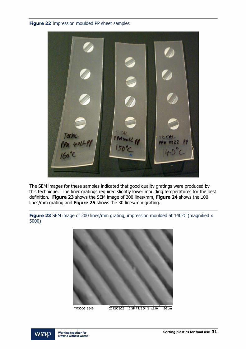
Sorting plastics for food use 31
Figure 22 Impression moulded PP sheet samples
The SEM images for these samples indicated that good quality gratings were produced by this technique. The finer gratings required slightly lower moulding temperatures for the best definition. Figure 23 shows the SEM image of 200 lines/mm, Figure 24 shows the 100 lines/mm grating and Figure 25 shows the 30 lines/mm grating.
Figure 23 SEM image of 200 lines/mm grating, impression moulded at 140°C (magnified x 5000)

Sorting plastics for food use 32
Figure 24 SEM image of 100 lines/mm grating, impression moulded at 150C (magnified x 3000)
Figure 25 SEM image of 30 lines/mm grating, impression moulded at 150C (magnified x 800)

Sorting plastics for food use 33
An initial test of these gratings at Bradford with a 650nm wavelength red laser pointer immediately demonstrated good results, see Figure 26.
Figure 26 Initial test with red laser pointer on impression moulded strip
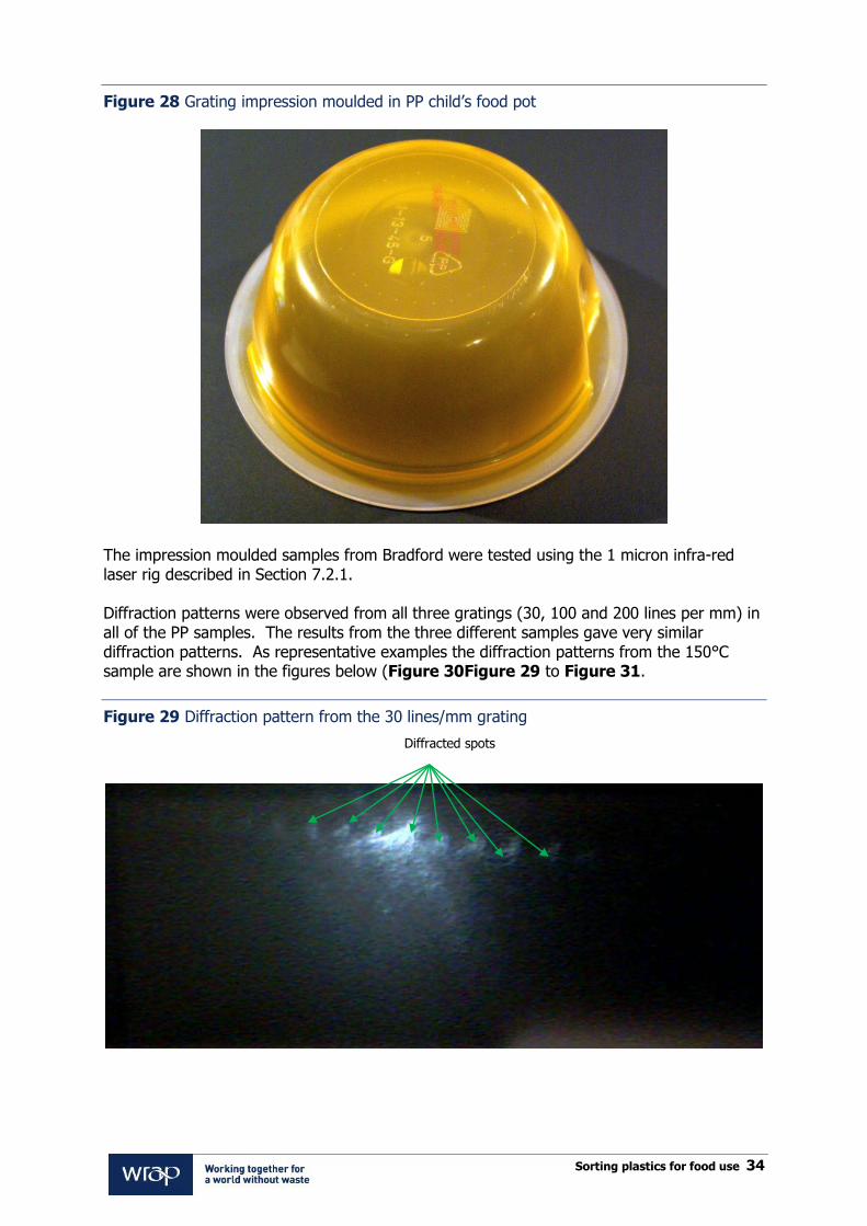
Given the promising results with the gratings moulded in plain PP sheet, it was decided to test the process with some real PP packaging. The impression moulding rig was used to create diffraction gratings in an injection moulded ice cream tub lid and a pot for a child‟s food product, see Figure 27 and Figure 28.
Figure 27 Grating impression moulded in PP ice cream tub lid
Sorting plastics for food use 34
Figure 28 Grating impression moulded in PP child‟s food pot
The impression moulded samples from Bradford were tested using the 1 micron infra-red laser rig described in Section 7.2.1. Diffraction patterns were observed from all three gratings (30, 100 and 200 lines per mm) in all of the PP samples. The results from the three different samples gave very similar diffraction patterns. As representative examples the diffraction patterns from the 150°C sample are shown in the figures below (Figure 30Figure 29 to Figure 31.
Figure 29 Diffraction pattern from the 30 lines/mm grating
Diffracted spots

Sorting plastics for food use 35
Figure 30 Diffraction pattern from the 100 lines/mm grating
Figure 31 Diffraction pattern from the 200 lines/mm grating
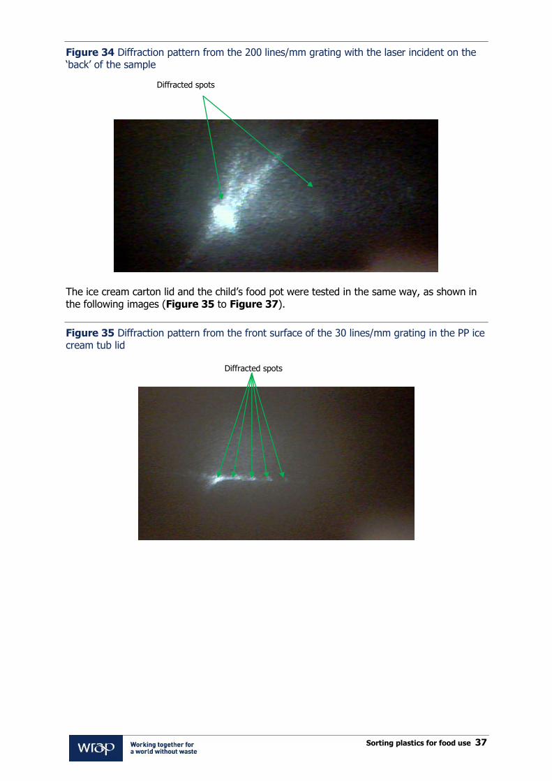
Note that the diffraction spots are spaced wider and are thus easier to resolve from each other with a finer grating structure. The diffraction patterns above were all obtained with the laser beam reflecting off the „front‟ surface of the PP – ie the side with the grating impressed in it. It also proved possible to observe diffraction patterns with the laser beam incident on the „back‟ of the sample, passing through the sample and diffracting off the grating on the other side. The diffraction patterns below were all recorded with the laser incident on the „back‟ of the sample, Figure 32 to Figure 34.
Diffracted spots
Diffracted spots

Sorting plastics for food use 36
Figure 32 Diffraction pattern from the 30 lines/mm grating with the laser incident on the „back‟ of the sample
Figure 33 Diffraction pattern from the 100 lines/mm grating with the laser incident on the „back‟ of the sample
Diffracted spots
Diffracted spots
Sorting plastics for food use 37
Figure 34 Diffraction pattern from the 200 lines/mm grating with the laser incident on the „back‟ of the sample
The ice cream carton lid and the child‟s food pot were tested in the same way, as shown in the following images (Figure 35 to Figure 37).
Figure 35 Diffraction pattern from the front surface of the 30 lines/mm grating in the PP ice cream tub lid
Diffracted spots
Diffracted spots
Sorting plastics for food use 38
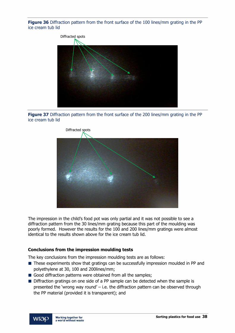
Figure 36 Diffraction pattern from the front surface of the 100 lines/mm grating in the PP ice cream tub lid
Figure 37 Diffraction pattern from the front surface of the 200 lines/mm grating in the PP ice cream tub lid
The impression in the child‟s food pot was only partial and it was not possible to see a diffraction pattern from the 30 lines/mm grating because this part of the moulding was poorly formed. However the results for the 100 and 200 lines/mm gratings were almost identical to the results shown above for the ice cream tub lid.
Conclusions from the impression moulding tests
The key conclusions from the impression moulding tests are as follows:
These experiments show that gratings can be successfully impression moulded in PP and
polyethylene at 30, 100 and 200lines/mm;
Good diffraction patterns were obtained from all the samples;
Diffraction gratings on one side of a PP sample can be detected when the sample is
presented the „wrong way round‟ – i.e. the diffraction pattern can be observed through
the PP material (provided it is transparent); and
Diffracted spots
Diffracted spots
Sorting plastics for food use 39
Diffraction patterns were successfully obtained from impression mouldings in commercial
PP tubs.
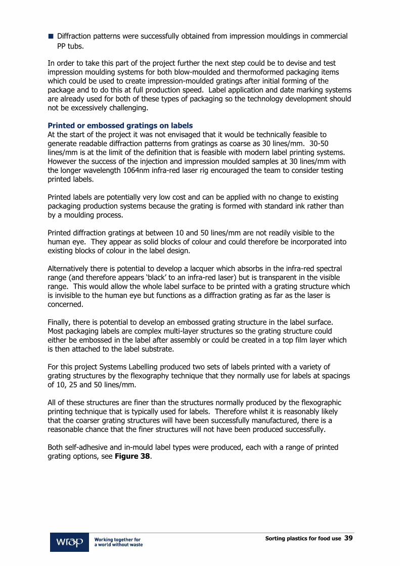
In order to take this part of the project further the next step could be to devise and test impression moulding systems for both blow-moulded and thermoformed packaging items which could be used to create impression-moulded gratings after initial forming of the package and to do this at full production speed. Label application and date marking systems are already used for both of these types of packaging so the technology development should not be excessively challenging. Printed or embossed gratings on labels At the start of the project it was not envisaged that it would be technically feasible to generate readable diffraction patterns from gratings as coarse as 30 lines/mm. 30-50 lines/mm is at the limit of the definition that is feasible with modern label printing systems. However the success of the injection and impression moulded samples at 30 lines/mm with the longer wavelength 1064nm infra-red laser rig encouraged the team to consider testing printed labels. Printed labels are potentially very low cost and can be applied with no change to existing packaging production systems because the grating is formed with standard ink rather than by a moulding process. Printed diffraction gratings at between 10 and 50 lines/mm are not readily visible to the human eye. They appear as solid blocks of colour and could therefore be incorporated into existing blocks of colour in the label design. Alternatively there is potential to develop a lacquer which absorbs in the infra-red spectral range (and therefore appears „black‟ to an infra-red laser) but is transparent in the visible range. This would allow the whole label surface to be printed with a grating structure which is invisible to the human eye but functions as a diffraction grating as far as the laser is concerned. Finally, there is potential to develop an embossed grating structure in the label surface. Most packaging labels are complex multi-layer structures so the grating structure could either be embossed in the label after assembly or could be created in a top film layer which is then attached to the label substrate. For this project Systems Labelling produced two sets of labels printed with a variety of grating structures by the flexography technique that they normally use for labels at spacings of 10, 25 and 50 lines/mm. All of these structures are finer than the structures normally produced by the flexographic printing technique that is typically used for labels. Therefore whilst it is reasonably likely that the coarser grating structures will have been successfully manufactured, there is a reasonable chance that the finer structures will not have been produced successfully. Both self-adhesive and in-mould label types were produced, each with a range of printed grating options, see Figure 38.
Sorting plastics for food use 40
Figure 38 Self-adhesive label structure
The gratings for the self-adhesive labels were formed either in the varnish or the ink. The gratings in the ink were formed from various combinations of ink for the lines and no ink for the spaces, or two different inks, one for the lines and the other for the spaces. The grating periods were 10, 25 and 50 line/mm. There were a total of 13 self-adhesive label options with various combinations of ink colours and grating spacings. An example of one of the self-adhesive label designs is shown in Figure 39. In this example the diffraction grating pattern is printed in the black sections of the label. The pattern is not visible to the human eye.
Glue for self-adhesive
Face Material – PP
Inks – Magenta, Cyan, Black and White
UV cured glue
PP over laminate with gloss varnish coating

Sorting plastics for food use 41
Figure 39 Example of self-adhesive label design
Figure 40 shows a set of self-adhesive label samples prepared by Systems Labelling for the trials.
Figure 40 Self-adhesive printed label samples from Systems Labelling

Sorting plastics for food use 42
In-mould labels are intended to be included in the moulding process when the package is formed; the labels are thus part of the plastic package rather than glued to the package. As for the self-adhesive labels, the gratings were formed either in the varnish or the ink. The gratings in the ink were formed from various combinations of ink for the lines and no ink for the spaces, or two different inks, one for the lines and the other for the spaces. The grating periods were 10, 25 and 50 lines/mm. There were a total of 12 different in-mould label designs with various combinations of inks and gratings. Figure 41 shows the in-mould label structure.
Figure 41 In-mould label structure
After printing by Systems Labelling the label samples were tested on the same 1064nm infra-red laser test rig as the impression and injection moulded samples.
Container material - PP
Face Material – PP, 45µm thick, fused to container
material below
Inks – Magenta, Cyan, Black and White
High gloss Varnish
Sorting plastics for food use 43
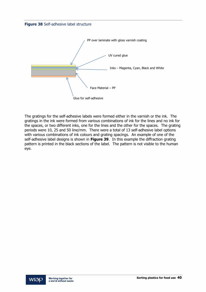
Self-adhesive labels Diffraction patterns were observed from the gratings in the ink at 10 and 25 lines/mm. Only gratings with either black or magenta ink and no ink in between the lines, produced an observable diffraction pattern. Figure 42 shows a grating in magenta ink with no ink in between (10 lines/mm) and Figure 43 shows the same but at 25 lines/mm. Labels with black ink with no ink in between are shown in Figure 44 (10 lines/mm).
Figure 42 Grating in ink on self-adhesive label - Magenta lines with no ink in between 10 lines/mm
Diffracted spots

Sorting plastics for food use 44
Figure 43 Grating in ink on self-adhesive label - Magenta lines with no ink in between 25 lines/mm
Figure 44 Grating in ink on self-adhesive label - Black lines with no ink in between 10 lines/mm
Diffracted spots
Diffracted spots

Sorting plastics for food use 45
The other ink combinations that did not produce a detectable diffraction pattern for the self-adhesive labels were:
Black lines with white ink in between, 10, 25 and 50 lines/mm;
Cyan lines with black ink in between, 10, 25 and 50 lines/mm;
White lines with no ink in between, 10, 25 and 50 lines/mm;
Black lines with no ink in between, 25 and 50 lines/mm; and
Magenta lines with no ink in between, 50 lines/mm.
It is likely that in these cases the ink ran across the boundary between the dark lines, meaning that there was insufficient contrast between the dark and light lines of the grating pattern. None of the gratings in the varnish produced observable diffraction patterns, probably because the varnish used was transparent to infra-red light.
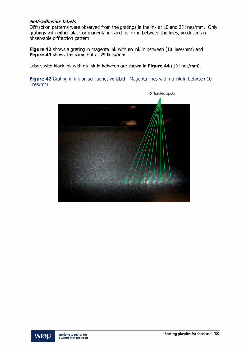
In-mould labels The only in-mould labels that produced observable diffraction pattern were the 10 lines/mm gratings with black and magenta ink, as can be seen in Figure 45 and Figure 46.
Figure 45 Grating in ink on in-mould label - Magenta lines with no ink in between, 10 lines/mm
Diffracted spots
Sorting plastics for food use 46
Figure 46 Grating in ink on in-mould label - Black lines with no ink in between, 10 lines/mm
The other gratings in ink combinations that did not produce a detectable diffraction pattern on the in-mould labels were:
Black lines with white ink in between, 10, 25 and 50 lines/mm;
Cyan lines with black ink in between, 10, 25 and 50 lines/mm;
Black lines with no ink in between, 25 and 50 lines/mm; and
Magenta lines with no ink in between, 25 and 50 lines/mm.
None of the gratings in the varnish produced detectable diffraction patterns.
Conclusions from the tests with printed labels
The key conclusions from the tests with the printed labels are:
Gratings can be successfully produced in labels at 10 lines/mm, and possibly 25 lines/mm
using current high definition flexographic label printing technology;
Gratings could be produced in ink, but not in the surface varnish unless a varnish type
can be selected which is transparent in the visible spectral range but opaque to infra-red
light; and
Optimisation of the printing process together with the requirements of the optical readout
in mind should result in a marked improvement in the performance.
Diffracted spots

Sorting plastics for food use 47
8. Conclusions
Two of the food contact marking and detection techniques trialled in this project are worthy of further development because they appear to have good potential to be both technically and commercially viable for mass-market use. These are:
Labels coated with a machine readable ink; and
Diffraction gratings moulded into packages or printed or embossed on labels.
Trials in this project of label lacquers from two suppliers with two different recycling sorting machine suppliers were not successful because the materials used did not generate a strong enough signal for reliable detection but the concept is still exciting because the lacquers can cover the full label surface without interfering with branding and they are relatively low cost. Further tests of alternative detection techniques, probably CCD (Charge Coupled Device) line-scan cameras, which are already used in some recycling sorting applications and further development of the lacquer pigments are required to move this idea forward. The tests of both moulded and printed diffraction grating structures for this project were successful, even in certain cases with relatively coarse grating structures of 10-30 lines/mm. The technique should be very low cost to implement because gratings can be formed in containers or labels without the need for additional materials. Exactly the same spacing of diffraction pattern will be generated by a 25 line/mm diffraction grating with a 1064nm wavelength laser, whether the pattern is injection moulded, impression moulded or printed and whether it is viewed by reflection or with the laser shining through the package. This means that packaging designers can potentially incorporate identification gratings in their products in many different ways. Longer term there is potential to record additional data in diffraction gratings by including more than one grating spacing/pattern within the structure or by creating a grid of lines at right angles to each other. This could in principle be used to record not just food contact status but polymer type or even product type, and therefore this technology has potential for wider application, beyond food contact sorting. Many technical challenges remain for the development of diffraction gratings as a commercially viable food contact marking technique. The principal challenges identified in this work include:
For the detection system:
o Geometry of the sensing system (packages falling down chute or placed on a
moving belt);
o Image analysis technique;
o Minimum size required for the diffraction pattern on the package in order to
ensure reliable detection. If the grating is coarse and therefore easier to form,
it will generate diffraction patterns where the spots are closer together and
therefore harder to detect;
For printed gratings:
o Optimise printing technique to improve line definition (includes development
of high definition printing plates and optimisation of ink types);
o Investigate alternative surface varnishes which are transparent in the visible
range but opaque in the infra-red;
o Investigate building embossed grating structures into the label top layer;
For moulded gratings:

Sorting plastics for food use 48
o Engrave diffraction gratings on harder mould materials;
o Test injection and impression moulding at production volume to ensure that
mould wear is not excessive; and
o Develop at-line impression moulding techniques that can work at commercial
production volume.
For either marking technique (pigmented lacquers or diffraction gratings) it will be necessary to conduct other, largely commercial, work in order to demonstrate the commercial viability of full uptake of the approach, including:
Persuade sorter manufacturers to develop the machines required for detection;
Persuade recyclers to invest in the required sorting machinery;
Work with retailers, brand owners and converters to agree standards for the marking
system; and
Persuade packaging converters and label makers to adopt the standard and invest in any
moulding or label system changes that are required.

Sorting plastics for food use 49
Appendix A – Summary of induction sensing trials
This appendix summarises the trials of three different induction sensing techniques that were completed during this project. Although the second and third techniques offer the potential for sensing of food contact marking with packages in any orientation and have potential to be implemented on labels at relatively low cost it was decided not to progress these techniques beyond the proof of concept stage because they are still likely to be more expensive and difficult to implement for mass market packaging than the other techniques short listed in this project. 1. Foil shapes with conventional metal sorter The simplest option is to fix a foil shape to the rear of the label. A review of the theory of induction sorting indicated that the strongest signals are generated by samples that cover large areas. The thickness of the foil is much less significant than its area. To test this in practice a set of samples was made up with foil discs and other metal shapes mounted on 28mm thick blocks of wood which were then fixed to a piece of Axion Polymer‟s own „Axfoil‟ extruded polystyrene sheet. Each block was also fitted with 3mm cork spacers so that the samples could be presented to the induction sensor (which is mounted under the sorting machine belt) at a distance of either 3mm or 28mm. These two distances were chosen so that the sensitivity of the detection technique at different distances could be assessed. See Figure 47.
Figure 47 Cross section showing – sample facing away from the EM3 sensor

Sorting plastics for food use 50
A range of foil sample discs were produced, with thicknesses from 0.75 to 40 micron and diameters from 20 to 50mm, as shown in Figure 48.
Figure 48 Foil test samples prepared for induction sorting trials at TITECH
The samples were run over a test machine fitted with an induction sensor, as can be seen in Figure 49.
Figure 49 Combined NIR and induction sensing test machine at TITECH test facility

Sorting plastics for food use 51
All of the foil samples, even the very thin 0.75 micron discs, were readily detectable by TITECH‟s sensing system. Figure 50 shows an image from the TITECH system for 0.75 micron foil samples. The white patches in the image are the 0.75 micron foil discs mounted on wood blocks that are pictured in Figure 48, detected as they pass over the induction sensor.
Figure 50 Image from TITECH induction sensing system of 0.75 micron foil samples passing over the induction sensor
Detection coils
Although the foil markers were readily detected there is a fundamental disadvantage with this technique for PP recycling, which is that many non-food contact PP packages use metallised label substrates or metallised foil decoration. At the start of this trial it was thought that a large foil disc bonded to the back of a label would be more readily detected than the very thin metallised labels used in packaging. However modern induction sensing techniques are so sensitive that they could easily mis-sort packages with even a small amount of foil decoration as food contact items. For this reason it is recommended that this option should not be taken further as a food contact identification technique.
Sorting plastics for food use 52
2. Rectifier circuit or ‘Permalloy’ ferromagnetic strip – to create harmonics
This detection technique relies on detecting the additional electromagnetic frequencies created by the presence of a specially designed label in the electromagnetic field generated by an excitation coil. This type of technique is routinely used in commercially available security tag systems used in shops and libraries. The method requires a special label (or marker) to be printed on to the package. The label needs to be made from either a metal film with good electrical conductivity or a ferromagnetic material (a material that can be magnetised in a magnetic field). For metal films, aluminium is the obvious choice since it has good conductivity and is already used in thin film form on food packaging. It is possible that the circuit could also be printed using conductive ink. In terms of ferromagnetic films, ferrite is one possibility but permalloy is a better choice because it is likely to be easier to detect due to its higher relative permeability; it is also readily available in thin film form. A practical implementation of the rectifier label could be produced using printed electronics by companies such as Pragmatic Printing Ltd15, a printed electronics company located near Cambridge. This new technology involves using low cost printing techniques to deposit thin films of conductors and semiconductors on to plastic substrates. Conversations with this company suggest that all the components for the rectifier label can be printed and within a year a suitable, low cost label could be developed. For the ferromagnetic label option, one could simply use strips of permalloy, or potentially at lower cost, pieces of magnetic tape. There is tape on the market that that contains a number of magnetic layers developed for similar electromagnetic detection purposes in other industries. The detection technique relies on the special label (or marker) producing „harmonics‟ of the electromagnetic field from the excitation coil. This will occur when the label has a non-linear response to the excitation field. This non-linear response can be achieved by constructing the label in two ways such that it is either:
A rectifier – a coil of an electrical conductor with a rectifying element in the coil so that
the electrical current induced by the excitation field can only travel in one direction
around the coil; or
A ferro-magnet - a strip of a ferromagnetic material which undergoes magnetic phase
changes as the excitation field oscillates.
Both these types of labels result in non-linearities that produce electromagnetic fields at
frequencies that are harmonics of the excitation field. The rectifier label consists of a conducting loop containing a diode, thus ensuring that current can only travel in one direction around the loop. This has the effect of creating a non-linearity and thus harmonics of the excitation field produced by the rectifier label. These harmonics are electromagnetic waves at multiples of 2,3,4,5.... of the frequency of the excitation field.
15www.pragmaticprinting.com
Sorting plastics for food use 53
The harmonics are detected by monitoring the signal from the detection coil, filtering out the frequency of the excitation coil and looking for any signal at multiples of 2,3,4,5.... of that frequency. The presence of these harmonic frequencies is a unique signal that indicates the presence of a label close to the detection coil. It is extremely unlikely that such harmonics would be generated by the metallised labels normally found in the waste packaging stream. It was not possible to test this technique at production scale so a laboratory rig was constructed to test the concept of harmonic detection of labels. For the proof of concept experiment, a simulated rectifier label was produced from two, 20mm diameter turns of 0.56mm diameter copper wire with a diode connected across the ends of the wire. Two turns of wire were used so that for the excitation coil used, sufficient voltage was generated to exceed the threshold of the diode at a frequency of 150kHz. It was calculated that for a realistic rectifying label consisting of two turns of 10 micron thick aluminium, 0.5mm wide and 20mm diameter printed on to the packaging material, the impedance would be less than 1 Ohm. Therefore in some experiments a 1 Ohm resistor was also added into the simulated loop to more accurately simulate the maximum impedance that would be expected in a realistic implementation.
The simulated ferromagnetic label was a strip of permalloy, 20mm long, 2mm wide and 125microns thick. This type of label is commercially available, since they are regularly used in anti-theft systems used in shops. Permalloy has a high relative permeability so that it becomes strongly magnetised even in weak fields and thus is expected to produce a large harmonic generation effect when compared with other readily available materials. The elongated shape is chosen so that self–depolarisation is weak and the magnetic dipole moment is large. This has the effect of giving very abrupt switching of the magnetisation along the length of the strip in the presence of the oscillating electromagnetic field from the excitation coil. This rapid switching causes a non-linearity, which in turn generates harmonic frequencies of the excitation electromagnetic field which can be detected by the detection coils in the same way as with the rectifier labels. Figure 51 shows the simulated printed rectifier label circuit and the permalloy ferromagnetic strip that were used for the proof of concept harmonic detection trials.
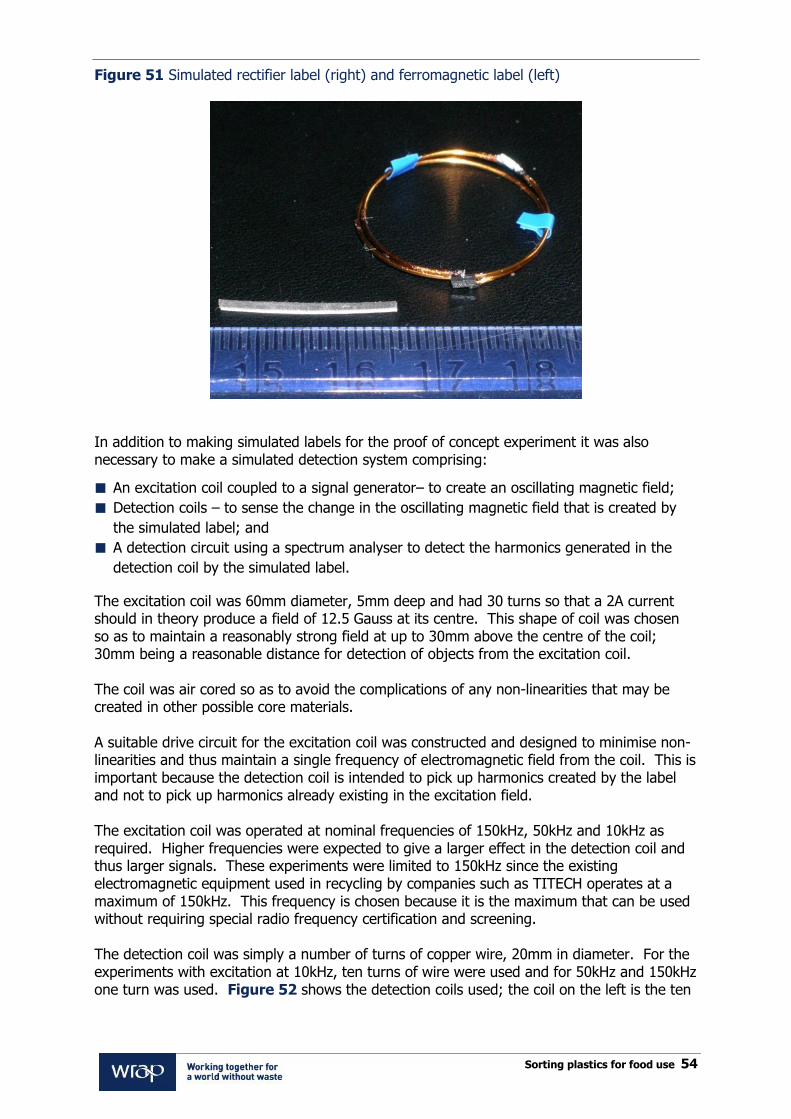
Sorting plastics for food use 54
Figure 51 Simulated rectifier label (right) and ferromagnetic label (left)
In addition to making simulated labels for the proof of concept experiment it was also necessary to make a simulated detection system comprising:
An excitation coil coupled to a signal generator– to create an oscillating magnetic field;
Detection coils – to sense the change in the oscillating magnetic field that is created by
the simulated label; and
A detection circuit using a spectrum analyser to detect the harmonics generated in the
detection coil by the simulated label.
The excitation coil was 60mm diameter, 5mm deep and had 30 turns so that a 2A current should in theory produce a field of 12.5 Gauss at its centre. This shape of coil was chosen so as to maintain a reasonably strong field at up to 30mm above the centre of the coil; 30mm being a reasonable distance for detection of objects from the excitation coil. The coil was air cored so as to avoid the complications of any non-linearities that may be created in other possible core materials. A suitable drive circuit for the excitation coil was constructed and designed to minimise non-linearities and thus maintain a single frequency of electromagnetic field from the coil. This is important because the detection coil is intended to pick up harmonics created by the label and not to pick up harmonics already existing in the excitation field. The excitation coil was operated at nominal frequencies of 150kHz, 50kHz and 10kHz as required. Higher frequencies were expected to give a larger effect in the detection coil and thus larger signals. These experiments were limited to 150kHz since the existing electromagnetic equipment used in recycling by companies such as TITECH operates at a maximum of 150kHz. This frequency is chosen because it is the maximum that can be used without requiring special radio frequency certification and screening. The detection coil was simply a number of turns of copper wire, 20mm in diameter. For the experiments with excitation at 10kHz, ten turns of wire were used and for 50kHz and 150kHz one turn was used. Figure 52 shows the detection coils used; the coil on the left is the ten

Sorting plastics for food use 55
turn coil used at 10kHz and the coil on the right is the single turn coil used at 50kHz and 150 kHz. Both coils are 20mm in diameter.
Figure 52 Detection coils
The simulated label was held above the excitation coil at various heights up to 30mm. The strength of the harmonics detected by the detection coil was measured using a spectrum analyser.
A sample of metallised food packaging (aluminium less than 1µm) or a piece of 8µm thick aluminium foil was held between the excitation coil and the simulated label to evaluate the effect this would have on the signal. This was done because aluminium foil is routinely used in packaging and there was a concern that it could affect the detection of the rectifier label. 8µm aluminium is understood to be the thickest aluminium routinely used in packaging applications, and theory suggests that the thicker the aluminium, the greater the screening effect it will have on the harmonic signal from the rectifier label.
At an excitation frequency of 150kHz the 2nd, 3rd and 4th harmonics were detected (see Figure 53 for the traces from the spectrum analyser). These harmonics were also observed in the presence of the metallised food label, but not in the presence of the 8µm foil. The trace shown on the left in Figure 53 is the „null‟ signal without the rectifier label. The trace on the right has the rectifier label 14mm above the excitation coil; harmonics 2, 3 and 4 are visible.

Sorting plastics for food use 56
Figure 53 Traces from the spectrum analyser for harmonic generation with the simulated rectifier label
Neither the metallised food packaging nor the 8µm foil created harmonics on their own. This is an important result because it demonstrates that the coil arrangement generates a uniquely identifiable signal. Although this detection technique requires significant sensor development effort by the sorting machine makers it was shown to work at frequencies with which they are already familiar and produced a very distinctive signal. Rapid progress is being made in the development of low cost printable electronic circuits and ferromagnetic strips are already available at low cost so there is a good chance that this technique could become commercially viable in the future.
Excitation
frequency 3rd Harmonic
4th Harmonic
2nd Harmonic

Sorting plastics for food use 57
3. Ferrite strip – creates phase shift
This technique detects a phase shift caused by the presence of the label in the electromagnetic field. The phase shift is between the electromagnetic field picked up by the detection coil and the field from the excitation coil. This technique is frequently employed in industrial metal detection. The experimental setup was the same as with the harmonic generation described in Appendix 2. It used the same ferromagnetic label (the 20mmx2mm, 125micron thick permalloy strip). The only difference was in the way the signal from the detection coil was analysed. In these experiments an oscilloscope was used to record the phase shift between the signal from the excitation coil and detection coil. In some experiments a sample of metallised food packaging (aluminium less than 1µm) or 8µm aluminium foil was inserted between the excitation coil and the permalloy label to establish if these materials affected the signal detected. Figure 54 shows the spectrum analyser traces for the signals from the excitation and detection coils, illustrating the results observed at an excitation frequency of 10kHz. The upper trace is the signal from the detection coil and the lower trace is the signal from the excitation coil.
Figure 54 Three oscilloscope traces for excitation and detection coils
The left hand trace is the signal without a label present. The residual signal seen on the upper trace from the detection coil is pick-up from the excitation coil. Improvements to the detection circuit design could reduce this residual pickup. The centre trace is the signal with the ferromagnetic label only. Subtracting the residual pick-up from the excitation coil reveals a signal with a 63 degree phase shift relative to the excitation coil. The right hand trace shows the signal with the 8µm foil present (and no ferromagnetic label). This trace shows a phase shift of 39 degrees. Thus there is a clear difference between the signal observed from the ferromagnetic label and the aluminium foil. When the metallised food packaging was inserted between the excitation coil and the label the effect was minimal.
The phase shift method can be used to detect the ferromagnetic labels at a range of excitation frequencies. The metallised food packaging did not significantly affect the results and would not interfere with detection of the ferromagnetic label. The aluminium foil did significantly affect the results. At low frequencies (10kHz) it is likely that the signal from the foil can be distinguished from the signal from the ferromagnetic label, however at higher

Sorting plastics for food use 58
frequencies it will become increasingly difficult to detect the ferromagnetic label in the presence of the foil. On the basis of these initial results it likely that the harmonic generation technique is likely to be a more robust and reliable detection method for food contact identification labels than the phase shift method.

www.wrap.org.uk/plastics