Summary Report for the Technical Interchange Meeting on ...
82
NASA/TM—2016–218219 Summary Report for the Technical Interchange Meeting on Development of Baseline Material Properties and Design Guidelines for In-Space Manufacturing Activities T.J. Prater, Q.A. Bean, N.J. Werkheiser, M.M. Johnston, E.A. Ordonez, F.E. Ledbetter, D.L. Risdon, T.J. Stockman, S.K.R. Sandridge, and G.M. Nelson Marshall Space Flight Center, Huntsville, Alabama March 2016
Transcript of Summary Report for the Technical Interchange Meeting on ...

NASA/TM—2016–218219
Summary Report for the Technical Interchange Meeting on Development of Baseline Material Properties and Design Guidelines for In-Space Manufacturing ActivitiesT.J. Prater, Q.A. Bean, N.J. Werkheiser, M.M. Johnston, E.A. Ordonez, F.E. Ledbetter, D.L. Risdon, T.J. Stockman, S.K.R. Sandridge, and G.M. NelsonMarshall Space Flight Center, Huntsville, Alabama
March 2016
National Aeronautics andSpace AdministrationIS02George C. Marshall Space Flight CenterHuntsville, Alabama 35812

The NASA STI Program…in Profile
Since its founding, NASA has been dedicated to the advancement of aeronautics and space science. The NASA Scientific and Technical Information (STI) Program Office plays a key part in helping NASA maintain this important role.
The NASA STI Program Office is operated by Langley Research Center, the lead center for NASA’s scientific and technical information. The NASA STI Program Office provides access to the NASA STI Database, the largest collection of aeronautical and space science STI in the world. The Program Office is also NASA’s institutional mechanism for disseminating the results of its research and development activities. These results are published by NASA in the NASA STI Report Series, which includes the following report types:
• TECHNICAL PUBLICATION. Reports of completed research or a major significant phase of research that present the results of NASA programs and include extensive data or theoretical analysis. Includes compilations of significant scientific and technical data and information deemed to be of continuing reference value. NASA’s counterpart of peer-reviewed formal professional papers but has less stringent limitations on manuscript length and extent of graphic presentations.
• TECHNICAL MEMORANDUM. Scientific and technical findings that are preliminary or of specialized interest, e.g., quick release reports, working papers, and bibliographies that contain minimal annotation. Does not contain extensive analysis.
• CONTRACTOR REPORT. Scientific and technical findings by NASA-sponsored contractors and grantees.
• CONFERENCE PUBLICATION. Collected papers from scientific and technical conferences, symposia, seminars, or other meetings sponsored or cosponsored by NASA.
• SPECIAL PUBLICATION. Scientific, technical, or historical information from NASA programs, projects, and mission, often concerned with subjects having substantial public interest.
• TECHNICAL TRANSLATION. English-language translations of foreign
scientific and technical material pertinent to NASA’s mission.
Specialized services that complement the STI Program Office’s diverse offerings include creating custom thesauri, building customized databases, organizing and publishing research results…even providing videos.
For more information about the NASA STI Program Office, see the following:
• Access the NASA STI program home page at <http://www.sti.nasa.gov>
• E-mail your question via the Internet to <[email protected]>
• Phone the NASA STI Help Desk at 757 –864–9658
• Write to: NASA STI Information Desk Mail Stop 148 NASA Langley Research Center Hampton, VA 23681–2199, USA
i
NASA/TM—2016–218219
Summary Report for the Technical Interchange Meeting on Development of Baseline Material Properties and Design Guidelines for In-Space Manufacturing ActivitiesT.J. Prater, Q.A. Bean, N.J. Werkheiser, M.M. Johnston, E.A. Ordonez, F.E. Ledbetter, D.L. Risdon, T.J. Stockman, S.K.R. Sandridge, and G.M. NelsonMarshall Space Flight Center, Huntsville, Alabama
March 2016
National Aeronautics andSpace Administration
Marshall Space Flight Center • Huntsville, Alabama 35812

ii
Available from:
NASA STI Information DeskMail Stop 148
NASA Langley Research CenterHampton, VA 23681–2199, USA
757–864–9658
This report is also available in electronic form at<http://www.sti.nasa.gov>
TRADEMARKS
Trade names and trademarks are used in this report for identification only. This usage does not constitute an official endorsement, either expressed or implied, by the National Aeronautics and Space Administration.

iii
TABLE OF CONTENTS
1. INTRODUCTION ............................................................................................................. 1
1.1 Motivation .................................................................................................................... 11.2 Objective ....................................................................................................................... 11.3 Technical Interchange Meeting Agenda ........................................................................ 11.4 Participation Summary ................................................................................................. 4
2. OVERVIEW OF IN-SPACE MANUFACTURING ACTIVITIES .................................... 7
3. SESSION I—IDENTIFYING CRITICAL MATERIAL PROPERTIESFOR IN-SPACE MANUFACTURING DESIGN AND ANALYSIS ............................... 11
3.1 Perspectives on Analysis for In-Space Manufacturing ................................................... 133.2 Perspectives on Design for In-Space Manufacturing ..................................................... 143.3 Identifying System-Level Properties (Wear) .................................................................. 163.4 Summary and Discussion ............................................................................................. 18
4. SESSION II—MATERIALS TESTING FOR IN-SPACE MANUFACTURING ............ 21
4.1 Testing for Additive Manufacturing of Metallics .......................................................... 214.2 Mechanical Testing of Composites ............................................................................... 234.3 Test Plan for the 3D Printing in Zero-G Technology Demonstration
Mission Specimens ........................................................................................................ 274.4 Summary and Discussion ............................................................................................. 32
5. SESSION III—DEVELOPMENT OF BASELINE MATERIAL PROPERTYDESIGN VALUES FOR IN-SPACE MANUFACTURING ............................................. 36
5.1 Materials Characterization Under Uncertainty: Leveraging Statistics to Advance Engineering ................................................................................................................... 37
5.2 Case Study: Friction Stir Weld Allowables Approach for External Tank ...................... 405.3 Overview of Flight Certification Methodology for Additive Manufacturing
of Metallics ................................................................................................................... 425.4 Summary and Discussion ............................................................................................. 46
6. SESSION IV—PRINTER CAPABILITIES AND USE SCENARIOS .............................. 49
6.1 The Additive Manufacturing Demonstrator Engine: A Case Study in Risk Mitigation for an Emerging Manufacturing Capability ..................................... 50

iv
TABLE OF CONTENTS (Continued)
6.2 Printer Utilization, Capabilities, and Use Scenarios ...................................................... 53 6.3 Strength Improvement of 3D Printed Plastic Parts ....................................................... 58 6.4 Summary and Discussion ............................................................................................. 59
7. FINAL SUMMARY AND OUTCOMES .......................................................................... 63
REFERENCES ....................................................................................................................... 66

v
LIST OF FIGURES
1. Breakdown of MSFC participants by organization ................................................... 6
2. ISM phased technology roadmap .............................................................................. 9
3. Materials development triangle ................................................................................. 12
4. Schematic of block-on-ring test ................................................................................. 17
5. Lamina tensile testing: (a) Unidirectional and (b) bidirectional ................................. 24
6. Schematic of compression test per ASTM D3410 (shear loading) ............................. 25
7. In-plane shear test for a ±45° composite specimen .................................................... 26
8. A-basis allowable value defined for normal, unstructured data ................................. 38
9. A-basis allowable value defined for normal, structured data ...................................... 38
10. EMU fan cap ............................................................................................................ 55
11. Impact of heat treatment on fracture surface morphologies for ABS material in (a) as-built condition and (b) following heat treatment .......................................... 59

vi
LIST OF TABLES
1. List of participants from MSFC ................................................................................. 5
2. Other participants (non-MSFC) ................................................................................. 6
3. Common mechanical tests for additively manufactured parts (metals) produced using SLM .................................................................................................................. 22
4. Common mechanical tests for additively manufactured parts (plastic) produced using FDM ................................................................................................................. 23
5. Catalog of phase I prints ............................................................................................. 28
6. Summary of specimens and tests ................................................................................. 32
7. Summary of tests needed in support of materials characterization activities ............... 35

vii
LIST OF ACRONYMS AND SYMBOLS
3D-CT 3D computed tomography
3DP 3D Print
ABS acrylonitrile butadiene styrene
Al-Li aluminum lithium
AMDE Additive Manufacturing Demonstrator Engine
AMF Additive Manufacturing Facility
AO atomic oxygen
ASME American Society of Mechanical Engineers
ASTM American Society of Materials Testing
CAD computer aided design
CAI compression after impact
CASIS Center for Advancement of Science in Space
CME coefficient of moisture expansion
CT computed tomography
CTE coefficient of thermal expansion
DOE design of experiment
EDM electron discharge machining
EMU extravehicular mobility unit
ET external tank
FDM fused deposition modeling
FSW friction stir welding

viii
LIST OF ACRONYMS AND SYMBOLS (Continued)
GH2 gaseous hydrogen
HDPE high-density polyethylene
HIP hot isostatic press
ISM in-space manufacturing
ISRU in situ resource utilization
ISS International Space Station
LED light-emitting diode
LEO low-Earth orbit
LH2 liquid hydrogen
LOX liquid oxygen
MAPTIS Materials and Processes Technical Information System
MIS Made In Space, Inc.
MISSE Materials International Space Station Experiment
MMPDS Metallic Materials Process Development Standards
MRB materials review board
MSFC Marshall Space Flight Center
MSG Microgravity Science Glovebox
MUA material usage agreement
NDE nondestructive evaluation
NIST National Institute of Standards and Technology
PBF powder bed fusion

ix
LIST OF ACRONYMS AND SYMBOLS (Continued)
PCRD process control reference distribution
PDP part development plan
PDR preliminary design review
PEEK polyether ether ketone
QMP qualified manufacturing process
RFI request for information
RT radiographic testing
SBIR Small Business Innovative Research
SEM scanning electron microscopy
SLM selective laser melting
STEM science, technology, engineering, and math
STL statistical tolerance limit
TIM technical interchange meeting
TM Technical Memorandum
TRL Technology Readiness Level
VPPA variable polarity plasma arc
V&V verification and validation

x
NOMENCLATURE
A A-basis design allowable
k tolerance (derating) factor
n sample size
s sample standard deviation
v degrees of freedom
X sample mean
g shear strain
e strain

1
TECHNICAL MEMORANDUM
SUMMARY REPORT FOR THE TECHNICAL INTERCHANGE MEETING ON DEVELOPMENT OF BASELINE MATERIAL PROPERTIES AND DESIGN
GUIDELINES FOR IN-SPACE MANUFACTURING ACTIVITIES
1. INTRODUCTION
1.1 Motivation
NASA Marshall Space Flight Center (MSFC) and the Agency as a whole are currently engaged in a number of in-space manufacturing (ISM) activities that have the potential to reduce launch costs, enhance crew safety, and provide the capabilities needed to undertake long-duration spaceflight. The recent 3D Printing in Zero-G experiment conducted on board the International Space Station (ISS) demonstrated that parts of acylonitrile butadiene styrene (ABS) plastic can be manufactured in microgravity using fused deposition modeling (FDM). This project represents the beginning of the development of a capability that is critical to future NASA missions.
Current and future ISM activities will require the development of baseline material proper-ties to facilitate design, analysis, and certification of materials manufactured using in-space tech-niques. The purpose of this technical interchange meeting (TIM) was to bring together MSFC practitioners and experts in materials characterization and development of baseline material prop-erties for emerging technologies to advise the ISM team as we progress toward the development of material design values, standards, and acceptance criteria for materials manufactured in space.
1.2 Objective
The overall objective of the TIM was to leverage MSFC’s shared experiences and collec-tive knowledge in advanced manufacturing and materials development to construct a path forward for the establishment of baseline material properties, standards development, and certification activities related to ISM. Participants were asked to help identify research and development activi-ties that will (1) accelerate acceptance and adoption of ISM techniques among the aerospace design community; (2) benefit future NASA programs, commercial technology developments, and national needs; and (3) provide opportunities and avenues for further collaboration.
1.3 Technical Interchange Meeting Agenda
The TIM consisted of an overview session followed by four more focused sessions/tracks addressing specific issues. The TIM sessions took place over the course of two weeks. Each session

2
included multiple presentations and case studies followed by discussion among members of the working group. Session abstracts are provided in sections 1.3.1–1.3.5. Detailed information about the content of the sessions, the presentations, and discussions are provided in sections 2–6 of this Technical Memorandum (TM).
1.3.1 Overview Session
Tuesday, July 7th, 20158:30–9:30 a.m., Building 4201, CR201Presentations: An Overview of In-Space Manufacturing Activities at MSFC, Niki Werkheiser
Niki Werkheiser, project manager for ISM, provided an overview of MSFC’s current and future ISM activities. These include the 3D Printing in Zero-G technology demonstration mission, utilization of the Additive Manufacturing Facility (AMF) that will become part of the ISS in 2016, and the development of an on-orbit recycling system for printer feedstock.
1.3.2 Session I—Identifying Critical Material Properties for In-Space Manufacturing Design and Analysis
Tuesday, July 7th9:30–11:30 a.m., Building 4201, CR201 Presentations: Structural Analysis Perspective for In-Space Manufacturing Usage, Sarah Sandridge, ES21Design Considerations for In-Space Manufacturing, Paul Thompson, EV32 (presented by Tracie Prater, EM42/EM60)Friction and Wear Properties of Additively Manufactured Parts, David Moran, EM10
This session focused on identifying the most critical properties that need to be characterized to support design and analysis of materials and parts manufactured using ISM capabilities. Sarah Sandridge, a structural analyst from ES21, presented on the fundamental properties required for structural analysis, grounding analyses of ISM parts with data from structural, instrumented test-ing, and the direct relationship between hardware criticality (classified based on consequences of failure) and the level of analysis detail needed. Paul Cravens, a designer from EV32, provided con-tent on material information needed for design applications. These included expected dimensional variations between the nominal computer aided design (CAD) geometry and the as-built parts, growth/shrinkage factors under thermal loads, attainable surface finish, and characteristic values for material consolidation/compaction/porosity. David Moran, a Pathways intern in EM10, spoke about the block-on-ring test procedure used to characterize friction and wear properties of other materials and how this technique could be applied to ISM.
1.3.3 Session II—Materials Testing for In-Space Manufacturing
Tuesday, July 7th1:00–3:00 p.m., Building 4201, CR201Presentations: Additive Manufacturing Materials Testing Support for Metallics, Will Tilson,

3
Jacobs Engineering, EM10Materials Testing for Composites, Dr. Alan Nettles, EM20 (presented by Dr. Frank Ledbetter, MITS, EM01)International Space Station 3D Printer Performance and Material Characterization Methodology, Quincy Bean, EM42
This session focused on development of test plans and procedures to provide the data needed to establish the baseline properties identified in session I with the level of fidelity needed for ISM parts. Quincy Bean, the principal investigator for the 3D Printing in Zero-G technology demonstration, presented the test plan for the flight and ground specimens from this mission and discussed how this plan might be modified or enhanced to support future ISM activities, including verification and validation (V&V) of parts for the utilization catalog. As a basis for comparison, Will Tilson from EM10 provided an overview of a typical test plan and testing techniques (includ-ing relevant standards) for additively manufactured metallic parts. Parts manufactured using FDM are single-material (ABS) but exhibit anisotropy that is an inherent consequence of the manufac-turing process. Dr. Alan Nettles (EM20) provided content on material tests and material property development approaches from composites to characterize anisotropy.
1.3.4 Session III—Development of Baseline Material Property Design Values for In-Space Manufacturing
Monday, July 13th12:30–3:00 p.m., Building 4201, CR201Presentations: Materials Characterization Under Uncertainty: Leveraging Stats to Advance the Engineering, Ken Johnson, NASA Engineering and Safety Center (NESC) C102Case Study: Friction Stir Weld Allowables Approach for External Tank, Carolyn Russell, EM32Overview of Flight Certification Methodology for Additive Manufacturing, Doug Wells, EM20
This session provided a broader look at the challenges inherent in establishing baseline material properties for materials manufactured using emerging technologies not represented in recognized materials standards and design handbooks. Ken Johnson, a statistician from C102, presented on statistical techniques (both traditional and alternative approaches) used in conjunc-tion with test data to define baseline material properties for design and analysis. Carolyn Russell of EM32 presented a case study on material property allowables development for friction stir welding (FSW) of the space shuttle external tank (ET). This program provided an example of incorporat-ing an emerging manufacturing technology into a flight program when NASA or industry-wide standards applicable to the process had not yet been written or developed. Many of the material property development challenges faced by ISM are similar to those confronted by the additive manufacturing metallics community. Doug Wells, EM20, presented on approaches to certification for additive manufacturing of metal parts used in propulsion systems and balancing requirements with risk.

4
1.3.5 Session IV—Use Scenarios and Printer Capabilities
Wednesday, July 15th9:00–11:00 a.m., Building 4601, Room 2117Presentations: Printer Capabilities, Use Scenarios, and the Utilization Catalog, Quincy Bean, EM42, and Tracie Prater, EM42/EM60Additive Manufacturing Demonstrator Engine Overview (AMDE), Graham Nelson, ER21Strength Improvement Techniques for 3D Printed ABS Plastic, Raj Kaul, EM42
This session primarily served to provide an overview of the capabilities of current (3D Print (3DP)) and future (AMF) ISS manufacturing facilities (presentation by Quincy Bean and Tracie Prater). The catalog of ground and flight prints for the 3D Printing in Zero-G technology demon-stration mission were discussed, and a template for the future utilization catalog (a publication con-taining photographs, details, and print files of parts that have been qualified for in-space printing and use) was presented. Participants in this session were encouraged to offer feedback on how ISM capabilities could be leveraged to support current and future projects in their organizations. Gra-ham Nelson from ER21 provided a summary of the Additive Manufacturing Demonstrator Engine (AMDE) (a small liquid engine comprised of components manufactured using selective laser melt-ing (SLM), an additive manufacturing metallic technique) as a utilization case study, highlighting how his team has leveraged additive manufacturing to reduce cost and compress their development schedule, demonstrate the capability of the additive manufacturing technology/process, mitigate some of the risk associated with the use of additive manufacturing upfront, and accelerate accep-tance of additive manufacturing among the design community. Raj Kaul, EM42, also spoke about potential techniques to improve the strength of ABS plastic parts manufactured using FDM. These improvements could accelerate use of ISM parts in engineering applications.
With 13 technical presentations and over 50 participants from MSFC, other NASA Centers, and several external organizations with unique expertise in materials and processes, the meeting represented a highly successful interchange of ideas and perspectives. In addition to the TIM itself, two ‘roadshow’ presentations were given to ES21 (a mechanical design group in space systems) and at the EM01 branch chiefs meeting prior to the larger meeting. The scope of these shorter briefings was mostly limited to the content in the “Printer Capabilities, Use Scenarios, and Utilization Cata-log” presentation in session IV and was intended to encourage participation in the TIM from these organizations. Following the TIM, participants were encouraged to offer feedback and additional thoughts through e-mail or by completing an online survey about the meeting. Many of the TIM participants and presenters also contributed to this summary report.
1.4 Participation Summary
The following is a summary of participants from the TIM:
• 45 participants from MSFC (table 1 and fig. 1).• Four participants from other NASA Centers (table 2).• 11 participants from external organizations (table 2).• 60 total participants.
5
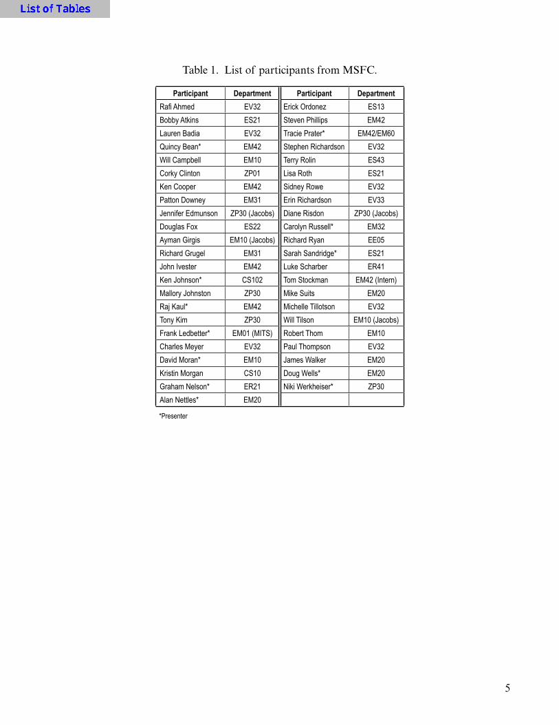
Table 1. List of participants from MSFC.
Participant Department Participant DepartmentRafi Ahmed EV32 Erick Ordonez ES13Bobby Atkins ES21 Steven Phillips EM42Lauren Badia EV32 Tracie Prater* EM42/EM60Quincy Bean* EM42 Stephen Richardson EV32Will Campbell EM10 Terry Rolin ES43Corky Clinton ZP01 Lisa Roth ES21Ken Cooper EM42 Sidney Rowe EV32Patton Downey EM31 Erin Richardson EV33Jennifer Edmunson ZP30 (Jacobs) Diane Risdon ZP30 (Jacobs)Douglas Fox ES22 Carolyn Russell* EM32Ayman Girgis EM10 (Jacobs) Richard Ryan EE05Richard Grugel EM31 Sarah Sandridge* ES21John Ivester EM42 Luke Scharber ER41Ken Johnson* CS102 Tom Stockman EM42 (Intern)Mallory Johnston ZP30 Mike Suits EM20Raj Kaul* EM42 Michelle Tillotson EV32Tony Kim ZP30 Will Tilson EM10 (Jacobs)Frank Ledbetter* EM01 (MITS) Robert Thom EM10Charles Meyer EV32 Paul Thompson EV32David Moran* EM10 James Walker EM20Kristin Morgan CS10 Doug Wells* EM20Graham Nelson* ER21 Niki Werkheiser* ZP30Alan Nettles* EM20
*Presenter

6
6
6
EM
EV
ES
ER
CS
EE
ZP
2
2
1
8
20
F1Figure 1. Breakdown of MSFC participants by organization.
Table 2. Other participants (non-MSFC).
Participant AffiliationDouglas Adams Vanderbilt UniversityAndrew Cain Southern ResearchVivek Dwivedi NASA Goddard Space Flight CenterJames Hawbaker Southern ResearchEd Garboczi National Institute of Standards and TechnologyPaul Kladitis University of Dayton Research InstituteRachel Muhlbauer Tethers UnlimitedMadison Parks Southern ResearchBrian Rice University of Dayton Research InstituteRichard Ricker National Institute of Standards and TechnologyJudy Schneider University of Alabama HuntsvilleDogan Timucin NASA Ames Research CenterEd Wollack NASA Goddard Space Flight CenterKevin Wheeler NASA Ames Research CenterWayne Ziegler Army Research Laboratory

7
2. OVERVIEW OF IN-SPACE MANUFACTURING ACTIVITIES
This introductory session provided an overview of ISM activities at MSFC. The ISM project is responsible for developing the manufacturing capabilities that will provide on-demand, sustainable operations during future NASA exploration missions. The scope of this work includes testing and advancing the candidate manufacturing technologies for in-space applications, as well as developing the skills and processes (such as defining V&V activities) that will enable the tech-nologies to become institutionalized. ISM utilizes the ISS as a testbed for technology demonstra-tion missions that will serve as the proving ground to transition these technologies to an orbital platform, enhancing crew safety and reducing reliance on Earth.
While 3D printing (and particularly the 3D Printing in Zero-G technology demonstration mission) are ISM’s highest profile activities, ISM includes work in many development areas that are key to reducing reliance on Earth-based platforms and enabling sustainable, safe exploration. These include:
• Feedstock recycling—The feedstock recycler, which will recycle/reclaim 3D printed parts and/or packing materials into feedstock materials, which can then be used to manufacture parts using 3D printing facilities on station.
• Printed electronics leverage ground-based developments to enable ISM of functional electronic components, sensors, and circuits.
• Printable satellites—The combination of 3D printing coupled with printable electronics enables the on-orbit capability to produce small satellites ‘on demand.’
• Multimaterial 3D printing—Additively manufacturing metallic parts in space is a desirable capa-bility for large structures, components with high strength requirements, and repairs. NASA is evaluating various additive manufacturing metal processes for use in the space environment.
• External structures and repairs—Throughout the lifecycle of space structures, astronauts will need to perform repairs on tools, components, and structures in space. A previous project at NASA Johnson Space Center investigated the use of structured light scanning techniques to cre-ate a digital model of damage and how additive manufacturing technologies such as 3D print-ing and metallic manufacturing techniques (including electron beam welding) could be used to perform repairs.
• Additive construction—These activities are focused on developing a capability to print structures on planetary bodies or asteroids using available resources.
The ISM program is focused on evolving manufacturing technologies from Earth-reliant to Earth-independent, work that is key to NASA’s exploration path. The ISS, currently funded

8
through 2024, will continue to serve as the primary testbed and proving ground for ISM technolo-gies. These include the 3DP technology demonstration, the AMF (future hardware that will operate on ISS under the management of the Center for the Advancement of Science in Space (CASIS)), the feedstock recycler, the development of the part utilization catalog, printable electronics, and investigations into additive manufacturing of metallics and external repair.
On Earth, the program includes work on certification and inspection processes, development of a characteristic material properties database for parts manufactured in the space environment using ISM capabilities, design of control systems and supporting software for ISM, and ground-based technology maturation and demonstrations. Many of these activities (such as the Additive Construction for Mobile Emplacement project, which seeks to develop a capability to print cus-tom-designed expeditionary structures from either native concrete or concrete derived from avail-able material on planetary bodies) represent intensive collaborations between the ISM and in situ resource utilization (ISRU) communities.
ISM is also a powerful tool to increase student engagement in science, technology, engi-neering, and math (STEM) educational activities and develop the next generation of engineers. Recently, NASA and the American Society of Mechanical Engineers (ASME) collaborated on a student competition, called the National Future Engineers STEM program, to design a tool that could be used by an astronaut on ISS. The winning part, a multipurpose maintenance tool, will be printed on ISS as part of phase II printer operations. More information about these and other NASA/ASME competitions can be found at <www.futureengineers.org>.
ISM has developed a phased technology roadmap (fig. 2) to capture the chronology of work needed to transition identified manufacturing technologies from Earth-based to exploration-based through the 2030–2040 timeframe. The immediate focus and first step is in-space 3D printing and recycling of plastics, but in future years the breadth and scope of activities is anticipated to rapidly grow to include printable electronics, ionic liquids (another ISRU collaborative activity), additive manufacturing of metallics, and development and demonstration of external repair capabilities. With the scheduled decommissioning of ISS in 2024, ISM could evolve (based on the technology maturation made possible by ISS technology demonstrations in the preceding years) to include fabrication labs on the Moon, asteroids, in cis-lunar space, or even the Martian surface. A fabrica-tion laboratory would provide on-demand manufacturing of structures, electronics, and parts via processes that utilize in situ and ex situ (renewable) resources. The suite of ISM technologies identi-fied in the roadmap will be key enablers for exploration and self-sustainment at any destination.

9
Earth-based
Pre-2012 2014 2015 2016 2017 2018 2020–25 2025 2030–403D Print Tech Demo
Demos: Ground and ISS ExplorationMars
LunarAsteroids
LagrangePointPlastic Printing
Demo
Add Mfctr.Facility
PrintableElectronics
Self-repair/Replicate
RecyclerSmallSatsACME
MetalPrinting
Lunar, LagrangeFabLabs• Initial Robotic/Re-
mote Missions• Provision Feedstock• Evolve to Utilizing In
Situ Materials (Natural Resources, Synthetic Biology)
• Product: Ability to Produce, Repair, and Recycle Parts and Structures on Demand; i.e. “Living Off The Land”
• Autonomous Final Milling to
ISS:Utilization/Facility Focus• In-space Recycler
Demo
• Integrated Facility Systems for Stronger Types of Extrusion Materials for Multiple Uses Including Metals and Various Plastics
• Printable Electronics Tech Demo
• Synthetic Biology Demo
• Metal Demo Options
• ACME Ground Demos
Ground and Parabolic Centric:• Multiple FDM
Zero-G Parabolic Flights
• Trade/System Studies for Metals
• Ground-Based Printable Electronics/Space-craft
• Verification and Certification Processes Under Development
• Materials Database• Cubesat Design and
Development
• 3D Print Demo• Future Engineer
Challenge• Utilization
Catalogue• ISM Cert Process• Add. Mfctr. Facility
(AMF)• In-Space Recycler
SBIR
• In-space Material Database
• External In-space 3D Printing
• Autonomous Processes
• ACME Simulant Dev and Test for Feedstock; Ground Demo
• In-space: 3D Print: First Plastic Printer on ISS Tech Demo
• NIAC Contour Crafting
• NIAC Printable Spacecraft
• Small Sat in a Day
• AF/NASA Space-based Additive NRC Study
• ISRU Phase II SBIRs
• Ionic Liquids
• Printable Electronics
Mars Multi-Material Fab Lab• Provision and Utilize
In Situ Resources for Feedstock
• FabLab: Provides On-Demand Manufacturing of Structures, Electronics, and Parts Utilizing In-Situ and Ex-Situ (Renewable) Resources. Includes Ability to Inspect, Recycle/Reclaim, and Post-Process as Needed Autonomously to Ultimately Provide Self-Sustainment at Remote Destinations.
PlanetarySurfaces Points Fab• Transport Vehicle
and Sites Would Need Fab Capability
• Additive Construction and Repair of Large Structures
F2
In-Space Manufacturing Phased Technology Development Roadmap
ISS Serves as a Key Exploration Test-Bed for the Required Technology Maturation and Demonstrations
Figure 2. ISM phased technology roadmap.
All of the technology development activities identified in figure 2 will require extensive materials characterization work for materials and parts/systems produced using ISM capabilities. The ISM team at MSFC is working to coordinate an integrated team to define and execute material property development activities to achieve the following objectives:
(1) Identify key material properties needed for design and analysis.
(2) Develop a materials characterization approach to establish baseline material properties for plastic parts manufactured in space using current and future 3DP facilities.
(3) Understand relationships between manufacturing process variables and resulting mate-rial properties. This includes characterizing the effects of filament layup/orientation, feedstock types and lots, and operating the FDM process in the microgravity environment. Printer-to-printer (and build-to-build) variability must also be characterized.
10
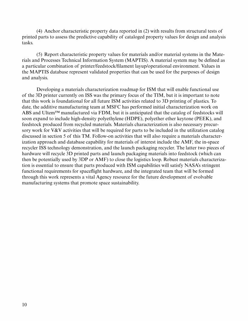
(4) Anchor characteristic property data reported in (2) with results from structural tests of printed parts to assess the predictive capability of cataloged property values for design and analysis tasks.
(5) Report characteristic property values for materials and/or material systems in the Mate-rials and Processes Technical Information System (MAPTIS). A material system may be defined as a particular combination of printer/feedstock/filament layup/operational environment. Values in the MAPTIS database represent validated properties that can be used for the purposes of design and analysis.
Developing a materials characterization roadmap for ISM that will enable functional use of the 3D printer currently on ISS was the primary focus of the TIM, but it is important to note that this work is foundational for all future ISM activities related to 3D printing of plastics. To date, the additive manufacturing team at MSFC has performed initial characterization work on ABS and Ultem™ manufactured via FDM, but it is anticipated that the catalog of feedstocks will soon expand to include high-density polyethylene (HDPE), polyether ether keytone (PEEK), and feedstock produced from recycled materials. Materials characterization is also necessary precur-sory work for V&V activities that will be required for parts to be included in the utilization catalog discussed in section 5 of this TM. Follow-on activities that will also require a materials character-ization approach and database capability for materials of interest include the AMF, the in-space recycler ISS technology demonstration, and the launch packaging recycler. The latter two pieces of hardware will recycle 3D printed parts and launch packaging materials into feedstock (which can then be potentially used by 3DP or AMF) to close the logistics loop. Robust materials characteriza-tion is essential to ensure that parts produced with ISM capabilities will satisfy NASA’s stringent functional requirements for spaceflight hardware, and the integrated team that will be formed through this work represents a vital Agency resource for the future development of evolvable manufacturing systems that promote space sustainability.

11
3. SESSION I—IDENTIFYING CRITICAL MATERIAL PROPERTIES FOR IN-SPACE MANUFACTURING DESIGN AND ANALYSIS
ISM represents a dramatic paradigm shift in the development and creation of space archi-tectures. Materials characterization is one of the key activities to unlocking the promise of these technologies for risk reduction in crewed exploration and realizing improved efficiencies in mainte-nance, repair, and logistics that could lead to a more sustainable, affordable supply chain model.
As a first step toward this vision, the ISM project seeks to develop a materials database that catalogs the characteristic properties of materials produced via ISM processes. Validated properties characterized in this database can be used as inputs to material and structural models for design and analysis. As the foundation for this work, the ISM team surveyed characteristic material prop-erties cataloged in the composites design handbook1 and similar aerospace materials handbooks as well as the tests and methodologies used to obtain representative data. The team interfaced with designers and analysts to identify ‘first tier’ properties that are most critical for design, analysis, and modeling. The ISM team also identified a need to anchor characteristic property data with results from structural tests of printed parts to assess the predictive capability of cataloged property values for design and analysis tasks.
Based on these interactions with the MSFC design and analysis communities, this session of the TIM was created to provide feedback on identification of material properties that must be characterized in order to fully utilize ISM capabilities. There are two facets to this task:
(1) Analysis—What do analysts need to model the parts made using this manufacturing process in a use scenario, and to what level of fidelity should those properties be characterized to enable predictive models? Currently, parts consist of a single material. One complexity of analysis for FDM parts lies in the manufacturing process itself, which inherently creates anisotropy in the as-built material. The degree of anisotropy and the directional dependency of material proper-ties must be characterized. For analysis, there are many additional outstanding questions related to failure modes, the level of detail needed in the model (i.e., modeling the material as bulk versus layer-by-layer, etc.). Sarah Sandridge, an analyst from ES22, discussed these topics in her presenta-tion, “Structural Analysis Perspective for In-Space Manufacturing Usage.”
(2) Design—The needs of the design community for ISM are aligned with those identified by analysts, but designers also have unique practical concerns that may not be captured within the scope of a traditional materials characterization program. These include material consolida-tion, dimensional variation (how dimensions vary from the nominal CAD geometry in the as-built part as well as how they change with temperature and degrade with use), and surface finish. Paul Thompson, a designer from EV32, provided content addressing these issues for the TIM.
The work identified in this portion of the TIM represents the precursor activities that are necessary to transition the 3DP ISM project from a technology demonstration to a capability that

12
can be fully utilized by designers of space hardware to enhance crew safety and enhance orbital supply logistics. These activities (identification of properties and characterization of properties at the coupon level to create a material property database for design and analysis) represent the base of the materials development triangle, which appears in MIL-HDBK-17 (fig. 3).1
Components
Subcomponents
Details
Elements
Coupons
Gene
ric S
pecim
ens
Nong
ener
ic Sp
ecim
ens Structural Features
Database
F3Figure 3. Materials development triangle.
The anchoring activities discussed in the analysis section (wherein designers compare pre-dictions of material behavior obtained using material properties from the coupon database as model inputs with results from instrumented tests of elements and nongeneric specimens) are nec-essary to assess whether properties as-characterized impart a predictive capability that accurately reflects material behavior under load and in use scenarios. This task is the critical work necessary to ‘scale’ the materials development triangle and achieve an institutionalized design and analysis capability for ISM. Within the context of the triangle, the utilization catalog (discussed in ses-sion IV), a library of parts that have been verified to meet all the stringent functional requirements for space flight hardware and are certified for printing on-demand and immediate application in their intended use environment, corresponds to the apex.

13
The identification of properties and subsequent manufacturing and testing of specimens to obtain those properties (the focus of session II) represents the foundational work that is the key and critical precursor for certification, institutionalization, and optimization activities associated with ISM. This work is expected to be an iterative process replete with technical challenges. There is a vacuum of standards for candidate ISM technologies (including, but not limited to, 3D print-ing), and many of the candidate ISM processes will exhibit a high degree of process sensitivity rela-tive to conventional manufacturing techniques (making it more difficult to define both operating envelopes that produce materials with adequate properties and requirements for raw materials like feedstock).
3.1 Perspectives on Analysis for In-Space Manufacturing
As additive manufacturing techniques and applications evolve, the need to analyze designs increases. A structural analysis perspective and approach to analyzing additive manufactured plastic parts is summarized in this section. In short, a good goal for structural analysis of additive manufactured plastic parts will be to simplify understanding as much as possible so the advantages of a quick manufacturing turnaround are not negated by the time required to design and analyze the part. A balance will need to be struck between analytical accuracy and efficiency of cost and schedule. It is understood that the material properties of additive manufactured plastic parts are expected to vary with filament placement, temperature gradients during the build, environment, and even the machine used to manufacture. Hopefully, these variations can be bounded with simple, conservative assumptions. This will involve investigation into how to develop a conserva-tive answer without being overly penalizing to the capabilities of the plastic parts. Note that the conservative answer is not necessarily the most accurate answer. Elements of this investigation will include understanding hardware criticality, developing fundamental properties, considering other necessary properties, and grounding the analysis through testing.
The level of analysis effort required for a given piece of hardware is related to how critical the hardware is. For example, in Fracture Control, NASA-STD-5019 is referenced to determine hardware classification.2 ‘Low risk’ hardware requires much less analysis effort than ‘fracture criti-cal’ hardware, and the understanding of materials in a fracture critical part is more important. In a similar way, hardware criticality will have an effect on the level of understanding that is required to assess additive manufactured plastic parts. Hardware in low criticality applications such as contained or nonstructural parts may require no analysis effort, and high-criticality applications where failures would be catastrophic in nature would require very detailed analysis and a thor-ough understanding of material behavior. The perspective outlined here assumes that the additive manufactured plastic parts being discussed will be used in applications of medium criticality: some analysis is needed, but the risks of the analysis being inaccurate are mitigated through things like redundancy and low possibility of crack-like flaws and flaw propagation.
An understanding of fundamental properties for the plastic parts would need to be devel-oped. Fundamental properties would include density, modulus of elasticity, Poisson’s ratio, and shear modulus. It is understood that the additive manufactured plastic parts will be anisotropic in behavior, so differences in the aforementioned properties for the different material directions will need to be quantified. Also, how the plastic filament is placed may affect properties. The filament

14
orientation will vary from layer to layer in the print. This is analogous to a composite layup where fibers are oriented differently for different layers. To avoid time-intensive and complex analysis, the effects of filament placement would ideally be captured by using conservative properties that envelop the effects. Understanding fundamental properties enables a smeared property approach to the analysis which, if viable, would allow for quick turnaround on analysis results to support design development.
Depending on the load environments and sensitivity of the plastic material to them, addi-tional necessary material properties understanding may be required. For example, moisture and thermal environments affect properties. Other necessary properties include flexural strength, flex-ural modulus, compressive strength, compressive modulus, bearing strength, coefficient of thermal expansion, tensile creep, fatigue, impact, and fracture. The way that the additive manufactured plastic parts connect to the adjoining structure may require testing for additional strength prop-erties such as fastener pull-through. The aforementioned properties are typical inputs to a stress analysis. Note that this is not an exhaustive list, and some design applications (i.e., extreme dynam-ics or thermal environments) will require more specialized considerations.
Grounding the analysis through testing will be critical to developing a sense of how valid simplified analysis methods are. This could be accomplished in a variety of ways. Instrumenta-tion could be added to specimens for already-planned tests. Or, even better, basic parts like beams or plates could be manufactured and instrumented, then subjected to simple loading scenarios. The basic parts could be manufactured in a variety of print orientations. Strain, deformation, and failure mode would be examined for each setup. Analysis models using simplified material property assumptions could be compared to the actual test results to see how effective the assumptions were in predicting actual behavior. The sensitivity of results to geometry, tool path, and other factors will show up in this effort.
Developing simple methods to analyze additive manufactured plastic parts will be an incre-mental process. Design applications of medium criticality will be identified, and fundamental properties will enable a smeared property approach to modeling the parts. Other necessary mate-rial properties will need to be investigated to ensure any significant failure modes are captured. Finally, the behavior of simplified parts under test loads will be compared to the behavior predicted by modeling assumptions. Through this process, additional areas of study may be identified and explored. Ideally, the process will yield a simple, conservative way to bound the material behavior of the plastic parts so that efficient analysis assessments will be possible.
3.2 Perspectives on Design for In-Space Manufacturing
Paul Thompson from the analysis group at MSFC (organization code EV32) provided con-tent on design for ISM (and specifically the concerns and properties that are of interest to design-ers) for this portion of the discussion.
The design group within EV32 has a 3D printer (a commercial off-the-shelf MakerBot®) capable of printing small plastic parts of ABS and Ultem. The build volume of this printer (9 in × 6 in × 6 in) is similar to the printer currently on ISS. Parts manufactured by EV32 with this

15
hardware are not intended to be functional items, but are used as visualization tools and to perform fit checks of small components that interface with one another. The capability allows designers to go from ‘art to part’ quickly and study design concepts in a preliminary form. While there is strong alignment between the needs of analysts and designers with respect to materials charac-terization, the properties that are of interest to the Spacecraft and Vehicle Systems Department extend beyond establishing baseline values for mechanical strength in tension, shear, and compres-sion. Practical design concerns such as material consolidation/compaction/porosity, dimensional variation (including both expected differences between the as-built part and the nominal CAD geometry as well as material shrinkage or growth in thermal environments), and surface finish also need to be considered when defining characterization activities. These additional design consider-ations are further explained as follows:
(1) A critical area of interest for the design community lies in characterizing the degree of material consolidation for 3D printed parts. This activity is key to design of parts for actual use, as loaded structural members are susceptible to failures created (or exacerbated) by voids. For the specimens from the 3D Printing in Zero-G technology demonstration mission, gravimetric density measurements will be derived from the weight of the specimens and the volume reported by structured light scanning (see the discussion of the full test plan for these parts in session II). Structured light scanning will also give an idea of open/surface porosity, but radiographic test-ing (RT) and computerized tomography (CT) scans will reveal any internal voids and characterize layer adhesion, spacing, regions of delamination, etc. in greater detail. Characterization of density for 3D printed parts is required to obtain a representative value for density/material consolidation (expressed as a percent of the theoretical density for the feedstock material and/or the same mate-rial manufactured using conventional techniques such as injection molding). This percent fill metric can be indicated on a design drawing in the flag notes. Defining acceptable/rejectable limits for density will be dependent on the criticality of the part and its application. For process development in additive manufacturing of metallics, materials produced with density values that are >98.95% of theoretical density are considered ‘fully dense.’ Density measurement can in some ways be viewed as a nondestructive evaluation (NDE) technique since full material consolidation is a ‘first gate metric’ to ensure that the part has the highest possible strength.
(2) Designers also emphasized the importance of dimensional characterization of ISM parts. To design for ISM and ensure proper form and fit (at interfaces), it is essential to characterize the degree to which the dimensions of the as-built part can be expected to deviate from the nominal CAD geometry. For the 3D Printing in Zero-G phase I specimens, these data will be obtained from structured light scanning and will provide key information for geometric dimensioning and toler-ancing of parts produced using ISM capabilities. Thermal shrinkage or growth is to be expected in applications of additive manufacturing components, and the amount and rate of these changes is highly material dependent. As in porosity, the idea is to categorize this value for a particular material in a nominal way that allows for designers to make geometric allowances for growth and shrinkage in the designs. Designers also expressed a desire to understand warping in the part that may be a consequence of thermal interactions between the deposited material and the build plate and enveloping the conditions under which it occurs (are specific geometries more susceptible to the effect, the severity of warping in different processing regimes, the potential for mitigation through thermal control of the build plate, etc.).

16
(3) Surface finish (and what surface finishes are attainable with 3D printed parts) are another key informational need for design. Surface roughness is a concern in additive manufactur-ing of metallics since many of the components are intended for use in propulsion systems where high cycle fatigue performance is very sensitive to surface roughness (and the asperities in rough surfaces can serve as sites for crack initiation). For plastics, there are two primary reasons to mini-mize surface roughness in ISM parts: (1) Ensure proper fit at interfaces and (2) mitigate the risk of material ‘flaking off’ and impinging on or contaminating adjacent surfaces (typically a concern in systems with optics). This is an area where standards are nascent or nonexistent. (Root mean square values for metallics are well characterized and routinely indicated in flag notes of draw-ings, but comparable standards do not exist for plastic materials typically used in FDM processes.) To this end, there is a need to engage structural analysts to (1) characterize failure modes and (2) determine what surface asperities could be tolerated on a part in a specific application/use scenario. In parallel, work must be done to define characteristic surface roughness values for materials pro-duced using ISM capabilities. If there is a discrepancy between the values identified by the analysts and the attainable part surface finish characterized in a metrology laboratory, additional work may be necessary to adjust the manufacturing process to improve surface finish or develop/identify post-processing techniques (i.e., machining or etching) to attain the ‘target’ surface roughness value.
To enable design using ISM and institutionalize the capabilities, it will be necessary to develop standards and specifications similar to those that exist for metallics. In the nearer term, lessons learned from manufacturing demonstrations, development work, and preliminary char-acterization activities can be captured in a design handbook that summarizes best practices and guidelines relating to issues of primary interest to designers (material consolidation, dimensional variation, and surface finish, among others). Much of this information will be captured by the current test plan for the 3D Printing in Zero-G specimens (session II). Designers can be allies and advocates for the utilization, certification, and institutionalization of ISM capability by becoming early adopters of these technologies and leveraging these capabilities for their programs where appropriate.
3.3 Identifying System-Level Properties (Wear)
Additive manufacturing is becoming a major player in the aerospace community, where engineers increasingly rely on the process to impart significant cost and schedule savings, achieve optimized designs, and reduce touch labor relative to conventionally (subtractively) manufactured hardware. For in-space additive manufacturing applications, it is important that the tribology team take a proactive approach to characterization of the friction and wear properties of printed materi-als to assess their overall potential to serve as emergency repair parts. The Mechanical Test Branch at MSFC (organization code EM10) has proposed generating these needed data using the block-on-ring testing procedure currently used to characterize wear behavior of other, nonadditively manufactured materials.
Since wear processes occur primarily by virtue of material interaction, wear performance is typically characterized as a system-level property. The amount of wear, the rate at which it occurs, and the mechanism of material removal is influenced by a number of factors, such as the shape and hardness of the materials in contact, the dynamics/manner in which the opposing surfaces interact

17
with one another, lubrication, environment (moisture, humidity, temperature), loads, etc. In light of these considerations, wear was not initially considered to be one of the first tier properties identi-fied in the ISM team’s preliminary work on key material properties leading up to the TIM.
The characterization work proposed by the tribology group in EM10 consists of three phases:
(1) Testing of first article parts built using FDM materials (ABS, but potentially also Ultem) to establish baseline testing procedures and wear properties (wear resistance, material removal rates, changes in surface texture parameter, etc.). Wear behavior of native/conventionally manufactured analog materials may also be characterized for comparison.
(2) Manufacturing of test specimens using the 3DP ground test unit. This is a ground-based unit that is identical to the unit on board the ISS.
(3) Manufacturing of test specimens (identical to those in (2)) using the 3DP flight unit operating inside the Microgravity Science Glovebox (MSG) on the ISS.
The proposed method to characterize wear for these specimens is a variant of the American Society for Testing and Materials (ASTM) Standard Test Method for Ranking Resistance of Mate-rials to Sliding Wear Using Block-on-Ring Wear Test.3 The test specimens are a block-and-ring (fig. 4), and the test itself consists of applying a load to a lever that lowers the block onto the ring sample, which is spinning at a controlled rate. The frictional force is then measured on a load cell and is represented by a millivolt value. The millivolt value is converted to a load (units pound force) using a calibration curve, and the coefficient of friction is calculated based on this value. Precision weighing of the samples prior to and following the test is used to measure material loss. A wear scan measurement (using optical noncontact surface profilometry) is performed to assess areal material loss from the surface.
Figure 4. Schematic of block-on-ring test.
The procedure described here would use the ASTM standard for block-on-ring tests3 and be performed on the Falex Block-on-Ring Machine in the EM10 laboratory. Per this standard, the spindle speed is 72 ± 1 rpm with 5–15 lbf applied normal load and 0.5–1.5 lb dead weight on a 10:1 ratio lever system. The test runs for at least 600 cycles and can be run dry or with lubrication.

18
To date, the EM10 group has run tests on polymer-based samples additively manufactured at MSFC using FDM. The purpose of these precursor investigations (identified as part of the phase I work) is to establish testing parameters that will yield meaningful performance data that contribute to understanding (and ultimately prediction) of friction and wear capabilities of FDM-produced materials. The phase I work will also establish a performance baseline to compare addi-tively manufactured parts against. The timeline for this proposed investigation is estimated as 12 to 18 months, depending on the availability of the hardware and crew time.
Establishing friction and wear characteristics of specimens additively manufactured in the space environment is an important addendum to enabling their reliable use as characterization of the standard mechanical properties discussed in the structural analysis section. These tribological properties (coefficient of friction, wear rates under various pressures, loads, and part use scenarios) need to be characterized in order to establish usage guidelines and limits on part life for parts included in the utilization catalog.
3.4 Summary and Discussion
The key outcome of session I is the development of a list of properties that need to be char-acterized in order to develop a design and analysis capability for parts manufactured using ISM capabilities. These properties can be categorized as first tier (essential for analysis of a medium-criticality part) and ‘second tier’ (properties which are not required to perform an analysis, but knowledge of them improves the fidelity of the model and/or enables analysts to model additional use scenarios for a part). First tier properties include:
• Density• Modulus of elasticity• Poisson’s ratio• Shear modulus• Compressive strength
Second tier properties/characterizations are as follows:
• Flexural strength• Bearing strength• Tensile creep• Fastener pull-through• Fatigue• Wear• Impact resistance• Fracture characteristics• Dependence of properties on environment (thermal, moisture, etc.)• Thermal conductivity• Coefficient of thermal expansion (CTE)• Coefficient of moisture expansion• Dimensional variation

19
The first tier properties represent those that are minimally needed to perform analysis of components manufactured via FDM using analytical and computer models. The prioritiza-tion of properties at this stage is preliminary and migration of identified properties from one list to another is expected as parts and use scenarios for ISM parts are further defined. The current approach is to develop a plan to characterize first tier properties (with the goal of enabling very basic analysis) and perform additional tests to characterize second tier properties on an as-needed basis. For instance, a 3D printed bearing will require characterization of bearing strength, but this property is not essential for other applications. Similarly, tensile creep only needs to be accounted for in a model when a part experiences sustained tensile stresses over a long time constant that may induce transient deformation. Information to characterize thermal mismatch (properties such as CTE, thermal conductivity) will be required for dissimilar materials that are in contact with one another at elevated or reduced temperatures. Specific microgravity effects identified through the technology demonstration that require further study may also merit evaluation as ‘special’ material properties. One example is the peeling of printed parts on orbit. Characterization of warping in the part due to thermal effects and/or interactions between the deposited material and the build plate was of interest to designers (see session II). The phenomenon is likely specific to the material and build environment, but further study is needed to assess whether it can be mitigated by forced convection or adjusting the distance between the part and printer head as a means of thermal control. Special evaluations (of which ‘peeling’ is an example) may be necessary to establish design guidelines.
Obviously, it would be ideal to have all of the identified properties at the outset of a pro-gram (and the first and second tier lists are certainly not all inclusive), but the acquisition of prop-erty data is limited by budget, time, and (in the case of ISM parts) crew availability. While the station is continuously crewed with six astronauts who each perform about 35 hours of science each week, crew time is a commodity and, if processes are determined to operate differently in a microgravity environment and require additional characterization that cannot be performed on analogous ground units, will be a major factor in determining the scope of ISM activities. These considerations play into the number of test samples that are needed to establish characteristic values of the identified properties with the level of fidelity needed for engineering analysis is the subject of session III of the TIM. Given operational constraints and the desire to strike a bal-ance between analytical accuracy and efficiency of cost/schedule, one key to this work is negotiat-ing a middle road between generating volumes of data commensurate with statistically significant properties versus engineering significant properties. The former connotes traditional allowables programs such as those outlined in CMH-17 or similar aerospace design handbooks.1 The latter is associated with smaller scale or phased programs that take more of an evolutionary approach to database development. These issues will be addressed in detail in session III on statistical methods and approaches to generate design allowables. It is anticipated that an ability to characterize prop-erties for ISM applications will improve as the project evolves and there are statistical methods that account for this.
As discussed in the structural analysis section, characterization activities are complicated by the anisotropy of the as-manufactured material. For a fully anisotropic part, 21 independent elastic constants (the full stiffness matrix) must be considered. Quasi-isotropic or orthotropic anisotropy is

20
more manageable from a testing/property development perspective. At this time, degree of anisot-ropy exhibited in FDM ABS parts is not known. However, it is anticipated that parts for FDM will have material properties that are not only directionally dependent, but also highly process depen-dent (and characterizing process/property relationships and property sensitivities to processing conditions is yet another facet of materials characterization work). Testing to evaluate the degree of anisotropy and characterize the directional dependence of material properties are discussed in section 4.
Discussion in this session of the TIM drove home the point (also articulated in the struc-tural analysis presentation) that understanding of failure criteria and failure modes is essential to design and analysis work. Some of this knowledge can be obtained through the basic tests for analysis correlation described previously (e.g., cantilevered beam, simply supported beam). This work can occur (somewhat) in parallel with material property development (with the understanding that property inputs will improve as the project progresses), but should be a prioritized task since data are essential to define safety factors and margins for ISM and assess whether as-characterized material properties are predictive of material behavior in a use scenario.
The objective of the following section is to define the tests (and testing standards) that are needed to obtain the material properties identified in this TM and characterize material behavior with the fidelity needed to define design requirements and enable a predictive analysis capability.

21
4. SESSION II—MATERIALS TESTING FOR IN-SPACE MANUFACTURING
The presentations and discussion in session I focused on identification and prioritization of material properties needed to facilitate design and analysis of engineering articles manufactured using ISM capabilities. Session II seeks to establish the tests and standards needed to develop these characteristic material properties. In the context of the materials development triangle in figure 3, this work represents the coupon testing at the base. Coupon testing is the primary means of deriv-ing the data that will become the material property database and ultimately enable an analysis capability for elements, subcomponents, and components made with ISM processes and a defini-tion of design requirements for ISM.
4.1 Testing for Additive Manufacturing of Metallics
In the area of for-space additive manufacturing applications, MSFC’s core work lies in powder bed fusion (PBF) process development for metallic materials commonly used in propulsion hardware, primarily the nickel-based alloys Inconel 625 and 718, as well as Ti-Al-64V. Designers of propulsion systems are eager to incorporate PBF-based manufacturing techniques into their devel-opment as a way to reduce part counts, reduce or eliminate critical welds and brazes through the production of near-net shape parts, and realize cost and schedule savings possible with the reduc-tion of touch labor. The FDM process is disparate from processes used to additively manufacture metallics, and FDM materials will behave very differently from metals in testing and application. Test methods will of course also be different for metals and nonmetals, as these material classifica-tions are governed by different standards and (sometimes) overseeing organizations. However, both processes exhibit a high degree of process variability and do not yet have specific testing standards (although existing standards for testing of conventionally manufactured analog materials may be applicable). The additive manufacturing metallics and additive manufacturing plastics communities face similar challenges in development of material properties and process control. Additive manu-facturing of metallics is comparatively more advanced in terms of standards and specifications development; its rapid maturation in this regard has been driven by use of the technology to pro-duce materials in critical applications in aerospace and other sectors. As such, there is likely knowl-edge to be gleaned from metallics that can inform development of efficient and reliable test plans and procedures to characterize ABS plastics produced using FDM.
Will Tilson, a contractor with the Mechanical Test Branch at MSFC, provided a brief overview of mechanical testing regimes that are used to characterize properties of materials manu-factured using SLM, a PBF technique that uses a laser as the energy source to fuse particles and layers. Tilson’s presentation provided an overview of common mechanical tests and standards for additively manufactured metallic parts and what representative data can be obtained from these tests. The SLM team is very interested in characterizing the materials produced using SLM, because although the process fabricates metallics commonly used in the aerospace industry, the structure of the material that is produced by the SLM process is very different from the structure

22
produced by conventional techniques. The SLM team is trying to answer many of the same ques-tions that the ISM group faces, such as what machine parameters are most effective at producing parts with adequate material consolidation and mechanical properties? To what extent are the parts anisotropic? How does the 3D printing process influence the structure and properties of the material?
The mechanical test lab at MSFC has a suite of mechanical tests that can be used to gener-ate material property data. For SLM specimens, the most basic test is the tensile test. In a tensile test, a load cell records the load applied to the specimen and an extensometer measures how much the specimen stresses under the applied load. The ultimate tensile strength, yield strength, elastic modulus, and fracture elongation are obtained from the test data (plotted as a stress/strain curve) and provide a wealth of information about the strength and ductility of the material.
Other tests such as fatigue, fracture toughness, and fatigue crack growth are fairly standard for metallic materials and are necessary to enable design for the applications (mostly propulsion) in which SLM-produced parts will be used. All these mechanical tests follow the same concept as a tensile test: apply a load to a specimen, measure the load with a transducer, and measure how much the specimen deforms under the load. Tests are performed in a variety of environments, from elevated temperatures (up to 1,000 °F) down to the cryogenic temperatures associated with liquid nitrogen or liquid hydrogen (LH2) propellants. All of these tests have applicable ASTM standards (table 3), which guide test procedures to ensure that results can be readily compared with data from other researchers and materials handbooks where data were collected using the same techniques.4–10
Table 3. Common mechanical tests for additively manufactured parts (metals) produced using SLM.
Test TypeTest
Standard DataTensile ASTM E8 Ultimate tensile strength, yield strength,
elongation, stress-strain curvesHigh cycle fatigue ASTM E466 Stress vs.fatigue life curvesLow cycle fatigue ASTM E606 Strain vs. fatigue life curvesFracture toughness ASTM E1820 JIcFatigue crack growth rate ASTM E647 da/dN curvesCreep/stress rupture ASTM E139 Creep curves, notch rupture timeNotch tensile ASTM G142 Hydrogen embrittlement effects
High-cycle fatigue data are critical input for SLM materials and parts since they are used in propulsion systems with fracture-critical rotating components, but this type of testing is unlikely to be required for plastic parts in low- or medium-criticality applications. Table 4 shows tests that are commonly used to obtain material properties for conventionally manufactured plastics. The indi-cated test standards should also be applicable to plastics manufactured using FDM.11–13 Mechani-cal tests for plastics use different standards than tests for metals. The overall concept and data derived from the test are the same, but test specimen geometries and rates of load application differ significantly for metals and plastics.

23
Table 4. Common mechanical tests for additively manufactured parts (plastic) produced using FDM.
Test TypeTest
Standard DataTensile ASTM D638 Ultimate tensile strength, yield strength,
elongation, stress-strain curvesCompression ASTM D695 Ultimate compressive strength, yield compressive
strength, elastic modulus, stress-strain curveFlexural ASTM D790 Flexural strength, bending modulus
The mechanical test facility is currently performing the tests cataloged in table 4 on some ABS material as part of ISM materials characterization activities. The flexural tests use a three- or four-point loading apparatus where the specimen is supported at two points and loaded in the mid-dle by a one- or two-point load road. As noted in session I, flexure tests will no longer be initially performed on ISM materials since flexural strengths and moduli are not typically needed for analy-sis. For anisotropic materials (either metals or nonmetals), additional testing is required to under-stand the variation of properties with direction. Testing to characterize anisotropy is discussed in the presentation on mechanical testing of composite materials (sec. 4.2).
4.2 Mechanical Testing of Composites
ABS specimens produced using FDM are single-material and thus do not fit the definition of a composite. However, the process by which the parts are manufactured gives them an inher-ent degree of anisotropy (how anisotropic the material is at this stage in the development work is unknown). Anisotropy is characteristic of composites. Even though the materials we have are not composites and the decision was made not to test to composite standards, it is a value added exercise to look at materials testing for composites in order to better understand anisotropic mate-rial behavior and which established testing methods (or modifications to existing methods) can be implemented to efficiently characterize directional dependence of material properties.
Drs. Alan Nettles and Frank Ledbetter presented information on mechanical testing for composites. This discussion covered the mechanical testing of specimens prepared from composite laminae and laminates. Testing of constituents (fibers and resin separately) is not covered and test-ing of structural elements was not considered (with a singular exception for sandwich structures). Test specimens considered are typically simple (i.e., rectangular and flat) and are comprised of continuous carbon fiber-reinforced polymers. Three loading conditions are usually considered for ‘coupon-level’ testing of composites (i.e., the testing necessary to build up the material property database at the base of the pyramid in fig. 3): tension, compression, and shear.
4.2.1 Tension
The most common test performed on composite materials is the ASTM D3019 tensile test14 (plastics analog ASTM D63811 and metallics analog ASTM E84). Unidirectional (lamina) ten-sile properties (fig. 5(a)) are difficult to measure for a variety of reasons, but primarily due to the high strain and grip forces needed. As a result, bidirectional (90/0ns) laminates are usually tested (fig. 5(b)), then 0° and 90° properties are ‘backed out.’ Laminate tensile properties are measured using the same test method.

24
y
x
y
x(a)
(b)
F5
Figure 5. Lamina tensile testing: (a) Unidirectional and (b) bidirectional.
Tabs are not required on test specimens. In fact, it is recommended that the test organiza-tion use whatever means works best for gripping specimens; the strength of a laminate cannot be increased by geometric modification to the test specimen. In fact, most variability in measured properties is caused by coupon manufacturing and testing, which in turn results in lowered basis values.
4.2.2 Compression
The measured compressive strength of a laminate is typically less than the measured tensile strength, primarily because of many difficulties associated with obtaining ‘true’ compression in testing, as many factors affect the test specimens and loaded regions. Similar to tensile testing, it is best to use a bidirectional specimen to obtain unidirectional (lamina) properties.
There are two primary methods for introducing loads into compression specimens: (1) End loading, which is not recommended for composites as it tends to induce failure at the points of load application (a phenomenon known as end brooming), and (2) shear loading, which induces loading through grip faces, is the preferred technique. ASTM D341015 uses shear loading through tabs and uses a short test section to preclude buckling (fig. 6). Another primary method is ASTM D6641,16 which utilizes a combination of end and shear loading. Alternate compression test methods include ASTM D546717 sandwich beam and ASTM D173718 Boeing compression after impact (CAI). The sandwich beam method uses a sandwich specimen, which is comprised of two facesheets bonded to a lightweight core.17 The specimen is subjected to a four-point bend, which results in near-uniform compression in one of the facesheets. The method requires more material than standard tests, and is more expensive to conduct. The CAI test method18 is designed for dam-aged compression specimens only, and end brooming is a problem in this technique.

25
GripHousing
GuidePosts
F6Figure 6. Schematic of compression test per ASTM D3410 (shear loading).15
Factors that affect compression test results include specimen preparation, aspect ratio, holes, and the location of 0° plies. Specimens must have a polished finish, and parallelism is criti-cal. The aspect ratio of test specimens dramatically affects results, so consistency in specimen size is important. Also, the use of holes actually helps to induce failure in the gauge area in situa-tions where the specimen width is at least six times the hole diameter. Holes lead to more uniform results, with nearly the same calculated allowables as specimens tested without holes. The location of 0° plies affects strength, and it is best to keep 0° plies internal to the laminate to ensure higher strengths are measured.
4.2.3 Shear
The ASTM D351819 in-plane shear test is the most common means of measuring in-plane shear properties (fig. 7). It is actually a tensile test of a +45/–45ns specimen, and in-plane proper-ties are obtained by mathematical transformation of test results. The ASTM D7078 V-notch test20 is more versatile for obtaining both in-plane and interlaminar shear strengths, but is not recom-mended for measuring shear moduli. Other methods include rail shear, but are not used as fre-quently as other techniques since they are cumbersome and require additional material and test instrumentation.

26
γ ε ε= −x y12Shear Strain
F7
Figure 7. In-plane shear test for a ±45° composite specimen.
4.2.4 Variability
Several years ago, the statistics subcommittee of MIL-HDBK-17 (now CMH-17, the com-posites design handbook)1 investigated large masses of data to assess whether three batches and five rolls of material (the amount recommended by the document for material characterization) was really the minimal amount of material required to qualify a new material.
The findings of the committee are summarized as follows:
• Batch-to-batch variability was far less than panel-to-panel variability from a single roll of prepreg.
• The variability of supplied prepreg was no greater than that of aluminum.• The primary source of variability was not the composite material but the fabrication and testing
of coupons by the end user.
The results of the study imply that material allowables databases like those in CMH-171 are more a measure of how well various laboratories can manufacture and test coupons. It has further been noted that the statistical rigor of calculating allowables tends to be lost because of safety fac-tors and other knockdown factors.
4.2.5 Concluding Thoughts
The most reliable (and highest) strength data usually come from material manufacturers. Most end users now use the same database for the same material and then appropriately attribute their lower measured strength values and higher scatter to errors in processing the test specimens and the tests themselves.
Only test for properties that are critical to your specific application. While testing to ASTM and similar standards does facilitate a more robust comparison with existing data from other labo-ratories and material manufacturers, it is not a requirement for material property development. As previously stated, for composites, the variability associated with fabrication and testing of coupons by the end user is great and comparisons across datasets may reflect little more than consistency between test laboratories/methods (and thus should not necessarily be used to produce design data). Deviations from ASTM standards may be appropriate and acceptable for an application, but modifications should be documented. Documentation and consistency in applying test methodolo-gies is the key to the development of validated material property data that can be used by designers and analysts.

27
Further perspectives on composites test methodologies and their applicability to ISM mate-rials characterization activities appear in session IV.
4.3 Test Plan for the 3D Printing in Zero-G Technology Demonstration Mission Specimens
4.3.1 Background
The 3D Printing in Zero-G technology demonstration is the first payload to perform 3D printing (or, synonymously, additive manufacturing) in a microgravity environment over a long-time constant. This demonstration represents the first step towards development of an ISM capa-bility, which has the potential to enhance crew safety, enable long-duration missions where cargo resupply is not an option, and disrupt the orbital supply change to reduce reliance on Earth-based platforms. The 3DP payload was developed by the private company Made In Space, Inc. (MIS), under a NASA Small Business Innovative Research (SBIR) phase III contract. The 3D Printing in Zero-G technology demonstration was jointly funded by the NASA Human Exploration and Oper-ations Mission Directorate (through the Advanced Exploration Systems and ISS programs) and the Space Technology Mission Directorate (Game Changing Development program). The NASA team provided guidance for the payload design, early prototype and flight unit qualification testing, payload integration management, ground operations personnel, the flight to the ISS (SpaceX-4), and crew time for the printer’s operation.
The printer was designed to operate within the MSG, which provided containment, circula-tion to the outside of the printer and the electronics box, as well as cooling capabilities to prevent the printer from overheating. The 3DP payload used an extrusion-based process, FDM, to create ABS plastic parts. The choice of ABS as feedstock material was driven by its relatively low extru-sion temperature, low toxicity, use in other commercial printing units, and strength relative to other feedstocks. 3DP also contains its own environmental control unit, which is designed to regulate cooling and provide filtration of the air within the printer volume. Parts were printed from data files loaded on the device at launch, as well as an additional file uplinked to 3DP on orbit. Addi-tional parts are currently under consideration (see sec. 5 of this TM) and will be uplinked as crew time on ISS becomes available.
3DP was unloaded and remained in stowage until installation in MSG on November 17, 2014. Following installation, the 3DP payload was calibrated to identify the ideal distance of the print head from the print tray to assure adhesion of the prints to the tray. The phase I printing fol-lowing the calibration of the device occurred from November 24, 2014, to December 15, 2014, as crew time allowed. 3DP was removed from the MSG on December 16, 2014, and stowed until crew time becomes available for phase II prints. The phase I prints were brought to Earth on SpaceX-5 on February 10, 2015, and unboxed at MSFC on April 6, 2015.
4.3.2 Phase I Prints
For these experiments, the filament used was undyed ABS plastic at 1.75 mm diameter; the filament was heated to a temperature between 230 °C and 250 °C, at which time it was soft enough to feed through a 0.4-mm extruder tip. A set of 20 samples was built with the flight unit

28
and flight feedstock prior to launch (the ground control samples). These samples will be directly compared with the specimens printed using the flight unit during its time on ISS (November–December 2014). Mechanical test specimens were built with a ±45° layup with a solid infill. Detailed information about the specimens which comprise the ground and flight prints appear in table 5.
Table 5. Catalog of phase I prints.
Sample Quantity Sample Name Image
Characteristic Dimensions
(cm) Notes1 Calibration coupon Length: 3.00
Width: 3.00 Height: 0.41
This functional checkout and calibration coupon was printed to test calibration of the distance between the extruder and print plate.
1 Extruder head casing Proprietary image not available for release
Length: 5.89 Width: 4.09 Height: 0.51
This is a replacement part for the 3D printer itself; it is a side plate of the extruder casing.
1 Layer quality test specimen
Length: 1.00 Width: 1.00 Height: 3.00
This layer quality test specimen was printed to assess adhesion between layers and tolerances.
4 Tensile coupon Length: 11.35 Width: 1.91 Neck width: 0.61 Height: 0.41
The purpose of this coupon is to assess the tensile strength of the printed material at ±45° layup orientation.
3 Compression coupon Diameter: 1.27 Height: 2.54
Coupon to assess compressive strength of the printed material.
3 Flexural coupon Length: 8.81 Width: 0.99 Height: 0.41
Coupon to assess flexure properties of the printed material at ±45° layup orientation.
1 Negative range coupon
Length: 7.49 Width: 2.01 Height: 0.43
This coupon will be used to assess the perfor-mance, geometric accuracy, and tolerances of the 3DP unit.
1 Torque tool specimen Diameter: 3.00 Height: 2.50
This coupon demonstrates the ability of 3DP to fabricate a replacement crew tool.
1 Crowfoot specimen Length: 4.70 Width: 3.99 Height 1.30
This coupon demonstrates the ability of 3DP to fabricate a replacement crew tool.

29
Sample Quantity Sample Name Image
Characteristic Dimensions
(cm) Notes1 Structural clip
componentLength: 2.69 Width: 2.10 Height: 0.90
This is a structural connector/spacer that can be utilized to assemble avionics (specifically electron-ics cards) on orbit.
1 Positive range coupon Length: 6.12 Width: 2.01 Height: 0.51
This coupon will be used to assess the perfor-mance, geometric accuracy, and tolerances of the 3DP unit for positive relief features.
1 Sample container Body diameter: 4.03 Body height: 3.28 Top diameter: 4.60
This set will test the printer’s capability to produce two components in the same print. Part also has interlocking threads.
1 Microgravity structure specimen 1
Length: 2.46 Width: 2.21 Height: 0.51
This is a test of a part that would be difficult, if not impossible, to successfully 3D print in the pictured orientation due to gravity (i.e., sag, overhang, etc.). Specimen used to demonstrate how microgravity environment can be exploited to print structures that are not possible terrestrially (i.e., large overhangs without supports).
1 Wire tie* Length: 1.92 Width: 1.30 Height: 0.12
Part intended to assess flexibility of the material after printing.
021b Ratchet Length: 11.35 Width: 3.30 Height: 2.59
This part was uplinked, illustrating how a part can be designed on Earth and manufactured in space, on demand.
* Note: Wire tie is a ground control sample and ratchet is a flight sample. As such, the wire tie does not have a flight analog and the ratchet does not have a ground analog. No direct comparison between flight and ground can be made for these parts, but their respective evaluation can be used to ascertain the overall functionality of the machine and process.
4.3.3 Tests and Test Procedures
Samples are stored individually in clearly marked and sealed plastic bags. When not under-going testing, samples are kept in a dry place at room temperature and away from direct sunlight and moisture sources. Test conductors are required to wear latex or other suitable gloves during testing to avoid direct skin contact and potential contamination of the samples.
4.3.3.1 Photographic Inspection. Each ground sample, flight sample, and print tray will undergo a thorough visual and photographic inspection. During the inspection, photographs will be taken from different angles and with appropriate scale representation (e.g., a standard ruler)
Table 5. Catalog of phase I prints (Continued).

30
and with a digital camera with a megapixel resolution of 8 or greater for print-quality images. This inspection will allow notation of any anomaly or damage (for instance, any damage that occurred when the print was removed from the print tray). It will also aid in identification of any apparent visual differences between the flight and ground samples. Close attention will be given to any signs of delamination between layers, curling of the sample, surface quality, damage due to removal from the print tray, voids or pores, and any other visually noticeable defect. All of the findings from this inspection shall be given to MSFC’s Failure Analysis Branch, who will conduct the optical and scanning electron microscopy (SEM) analysis, to direct the concentration of their efforts to these defects.
4.3.3.2 Mass Measurement. A measurement of the mass using a calibrated laboratory scale accurate to 0.1 mg will be repeated five times to determine the calculated mean mass of the recorded measurements. A calculation of the density using the volume determined by structured light scanning will follow. The density data will provide information on void space or expansion of the material created during the printing process. Each flight sample will be compared with its respective ground sample to assess any differences; these differences will be noted.
4.3.3.3 Structured Light Scanning. Structured light scanning will also be completed to give a detailed, statistically valid dataset regarding the surface geometric variations between the printed part, CAD model, and part volume of the flight and ground samples. The scanning will take place at MSFC using the ATOS II Triple Scan blue light-emitting diode (LED) scanner. The scanner has an accuracy of ±12.7 μm at these volumes and the capability to capture stereoscopic images at a resolution of five million pixels per scan. The samples will be coated in talcum powder (nonre-active with the ABS plastic) to reduce the reflectivity of the sample surfaces and provide a more accurate scan. The talcum powder grain size is ≈10 μm in diameter and will have little effect on the measurements made by the scanner.
The software package that accompanied the ATOS scanner uses the stereoscopic images to capture the fringe pattern sent out from the central LED projector contained in the scanner. The software triangulates all of the surface data (using the grayscale pixels, black-and-white contrast from the fringe pattern) to determine the shape of the geometry. Through this process the software generates a complete 3D model of the object being scanned. The software also provides real time feedback to show if it is missing surface data anywhere on the object. The missing data will be cap-tured in subsequent scans to assure all sides of the object are scanned. The software package also has the capability of comparing the model of the object generated from the scans with the original CAD model from which the print was made. This will show any deviations between the nominal CAD geometry and the as-printed part.
4.3.3.4 Radiographic Testing and Computed Tomography. Two-dimensional oblique and 3D computed tomography (3D-CT) scans will be completed following structured light scanning on the mechanical test coupons (20 total from ground and flight) to image and characterize any inter-nal structures that could affect mechanical properties. The samples will be imaged on a Phoenix Nanome|x 160 using x-rays to determine the existence of any internal voids or evidence of delami-nation of the ABS layers. To conduct 3D-CT, 2D images will be acquired through a 360° rotational axis; the successive 2D images will be stitched together to form a 3D image of the sample. Depend-ing on the sample’s geometry, resolution as low as 8–10 μm is possible. If 2D measurements are

31
necessary, the computer numerically controlled table is calibrated to a measurement accuracy in the z-axis of 5 μm. The system has a detail detectability as low as 0.4 μm in 2D mode.
4.3.3.5 Mechanical Testing. Mechanical testing will commence after the nondestructive tests are complete. These tests will use ASTM standards. The tensile test will follow a standard method defined in ASTM D63811 and will provide information on the tensile strength, yield strength, elastic modulus, and fracture elongation of the printed material. A type I specimen would generally be chosen for this application, but the dimensions as prescribed by the ASTM standard were too large for the printer build volume to accommodate, a limitation which drove the alternate choice of the type IV specimen. The flexural test, ASTM D790,13 will provide the flexural stress and modulus of the printed samples. The compression test, ASTM D695,12 will determine the characteristic compressive stress and modulus of the specimens.
4.3.3.6 Optical Microscopy and Scanning Electron Microscopy. Optical microscopy and SEM images and analysis of selected specimens will detail the surface of the part, its microstruc-ture, and reveal layers and areas of the flight prints damaged by over-adhesion to the build tray (this will help determine the root cause of the over-adhesion issues observed during operation). Interlaminar regions will be investigated to ascertain if there is a difference in the layer adherence between flight and ground samples. Defects or anomalies noted by the visual and photographic inspections will be examined, as well as fracture surfaces from the mechanical tests.
Optical analysis performed on a Leica M205 A optical microscope will include six orienta-tions of the samples and focus on macroscopic characterization of visible regions with defects at an angle that best highlights the features of interest. Image magnifications of ×10, ×50, and ×100 will be acquired.
SEM will be performed using a Hitachi S-3700N. The uncoated samples will be imaged using secondary electrons in a low vacuum mode to investigate morphology and surface topog-raphy, particularly in areas of delamination. Fracture surfaces from mechanical testing and areas with evidence of over-adherence to the print tray will also be examined.
The overall test plan for the ground and flight specimens is summarized in table 6.
Testing of specimens is currently underway and expected to be complete by September 2015. The overall objectives for this phase of testing are as follows:
(1) Determine whether operational capability of printer is impacted by microgravity. (2) Assess effect of microgravity on FDM process, specifically through evaluation of mate-rial properties of parts produced via FDM in this environment and if/how they vary from their terrestrially manufactured counterparts.

32
Table 6. Summary of specimens and tests.
Sample Quantity Sample Name
Photographic/Visual
Inspection
Measure Mass, Calculate Density
Structured Light Scanning CT Scan
Mechanical Testing
(ASTM Standard)Optical, SEM
Analysis1 Calibration
couponX X X X X
1 Extruder head casing
X X X
1 Layer quality test specimen
X X X X X
4 Tensile coupon X X X X ASTM D638 X3 Compression
couponX X X X ASTM D695 X
3 Flexural coupon X X X X ASTM D790 X1 Negative range
couponX X X X
1 Torque tool specimen
X X X X
1 Crowfoot specimen
X X X
1 Structural clip component
X X X
1 Positive range coupon
X X X X
1 Sample container
X X X X
1 Microgravity structure specimen 1
X X X X X
1 Wire tie X X X X1 Ratchet X X X X X
Since testing is incomplete at the time of this writing, no assessments on the impact of microgravity on material quality can yet be made. Lessons learned from the analysis of these specimens will inform requirements for the design of next generation space-based polymeric 3D printers.
4.4 Summary and Discussion
This session focused on development of test procedures and standards to characterize the material properties identified in TIM session I. The primary lesson learned from additive manufac-turing of metallics is that test plans must be carefully developed to (1) capture the needs of the end-user and (2) provide sufficient information to validate the performance of the part in its intended use environment. Testing is key to V&V activities that will be required to certify designs and parts for usage (and inclusion in the utilization catalog).

33
The anisotropy of materials produced via FDM as well as the high specificity of the as-manufactured part to processing variables (in particular filament layup/orientation) present mate-rials characterization challenges that are very analogous to those faced by the composites and welding communities. The possibility of testing to composite standards rather than the standards for plastics summarized in table 4 was a key point of discussion in this session. While additively manufactured ABS, Ultem, etc. are anisotropic plastics, the directional dependence of the proper-ties of these materials should not drive ISM practitioners to evaluate them using standards writ-ten specifically for composites. This philosophy is reflected in a National Institute of Standards and Technology (NIST) document that surveys material testing standards for polymeric materials, which summarizes established International Organization for Standardization and ASTM stan-dards for materials testing of polymers and assesses their applicability to additively manufactured plastics.21 In most cases, NIST recommends against testing to polymer matrix composite, carbon fiber reinforced plastic, etc. standards. The overall recommendation for polymers produced using additive manufacturing techniques is to apply standards for plastics with guidance. (Guidance in this context may mean using test specimens of different dimensions from those indicated in the standard, testing at elevated temperatures or in immersive environments, and careful consideration and characterization of anisotropy.) The overall concensus from this document and discussion in the TIM session is that the ISM team should generally use standards for plastics when testing FDM-produced specimens, but modifications to the standard may be necessary. As discussed in Alan Nettles and Frank Ledbetter’s presentation, the ISM team should remain flexible with regard to standards implementation. At this stage in material property development activities, it is more important to test consistently and document test procedures than to follow standards that, as written, may not be best suited for the materials being evaluated. Development of standards and which existing standards are appropriate for additive manufacturing is an ongoing area of debate in the broader additive manufacturing community. There is an ASTM committee (F42) as well as a NIST group tasked with looking at these specific issues in more detail. The ISM team is aware of the activities of these groups and will incorporate their recommendations for best practices as they evolve.
It is important to critically examine the test plan for the 3D Printing in Zero-G technology demonstration mission since testing and evaluation of subsequent specimens from 3DP will likely follow a similar process flow. V&V activities for candidate parts to be included in the utilization catalog will also draw extensively from this plan. The objective of the testing for the ground and flight specimens is to characterize differences between specimens based on build environment and determine which of these differences are attributable to microgravity effects on the manufactur-ing process. As the test plan is currently defined, each print will undergo visual and photographic inspection, mass measurement, structured light scanning (to characterize dimensional variations between nominal CAD geometry and the as-built specimen), density evaluation (derived from mass measurements and volume calculation from structured light scanning), CT and RT to evalu-ate internal geometry/layer adhesion, mechanical testing (tensile, flexural, and compression), and optical microscopy/SEM. The decision was made to limit CT evaluation to mechanical speci-mens with the aim of establishing linkages between any unexpected failures in destructive testing and internal material flaws. Optical microscopy will be performed on all surfaces, and SEM will be performed on specimens that merit additional evaluation.
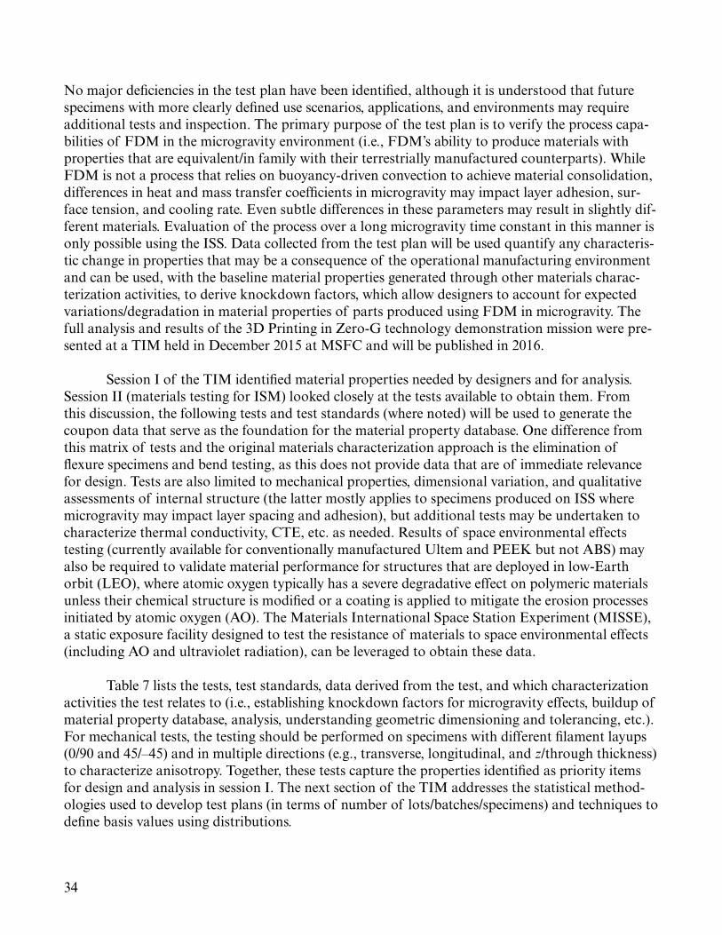
34
No major deficiencies in the test plan have been identified, although it is understood that future specimens with more clearly defined use scenarios, applications, and environments may require additional tests and inspection. The primary purpose of the test plan is to verify the process capa-bilities of FDM in the microgravity environment (i.e., FDM’s ability to produce materials with properties that are equivalent/in family with their terrestrially manufactured counterparts). While FDM is not a process that relies on buoyancy-driven convection to achieve material consolidation, differences in heat and mass transfer coefficients in microgravity may impact layer adhesion, sur-face tension, and cooling rate. Even subtle differences in these parameters may result in slightly dif-ferent materials. Evaluation of the process over a long microgravity time constant in this manner is only possible using the ISS. Data collected from the test plan will be used quantify any characteris-tic change in properties that may be a consequence of the operational manufacturing environment and can be used, with the baseline material properties generated through other materials charac-terization activities, to derive knockdown factors, which allow designers to account for expected variations/degradation in material properties of parts produced using FDM in microgravity. The full analysis and results of the 3D Printing in Zero-G technology demonstration mission were pre-sented at a TIM held in December 2015 at MSFC and will be published in 2016.
Session I of the TIM identified material properties needed by designers and for analysis. Session II (materials testing for ISM) looked closely at the tests available to obtain them. From this discussion, the following tests and test standards (where noted) will be used to generate the coupon data that serve as the foundation for the material property database. One difference from this matrix of tests and the original materials characterization approach is the elimination of flexure specimens and bend testing, as this does not provide data that are of immediate relevance for design. Tests are also limited to mechanical properties, dimensional variation, and qualitative assessments of internal structure (the latter mostly applies to specimens produced on ISS where microgravity may impact layer spacing and adhesion), but additional tests may be undertaken to characterize thermal conductivity, CTE, etc. as needed. Results of space environmental effects testing (currently available for conventionally manufactured Ultem and PEEK but not ABS) may also be required to validate material performance for structures that are deployed in low-Earth orbit (LEO), where atomic oxygen typically has a severe degradative effect on polymeric materials unless their chemical structure is modified or a coating is applied to mitigate the erosion processes initiated by atomic oxygen (AO). The Materials International Space Station Experiment (MISSE), a static exposure facility designed to test the resistance of materials to space environmental effects (including AO and ultraviolet radiation), can be leveraged to obtain these data.
Table 7 lists the tests, test standards, data derived from the test, and which characterization activities the test relates to (i.e., establishing knockdown factors for microgravity effects, buildup of material property database, analysis, understanding geometric dimensioning and tolerancing, etc.). For mechanical tests, the testing should be performed on specimens with different filament layups (0/90 and 45/–45) and in multiple directions (e.g., transverse, longitudinal, and z/through thickness) to characterize anisotropy. Together, these tests capture the properties identified as priority items for design and analysis in session I. The next section of the TIM addresses the statistical method-ologies used to develop test plans (in terms of number of lots/batches/specimens) and techniques to define basis values using distributions.

35
Table 7. Summary of tests needed in support of materials characterization activities.
Test Type Test Standard* DataRelated Characterization
ActivitiesMechanical Tests
Tensile ASTM D638 Ultimate tensile strength, yield strength, elongation, stress-strain curves, Poisson’s ratio**
Material property database development, analysis
Compression ASTM D695 Ultimate compressive strength, yield compressive strength, elastic modulus, stress-strain curve
Material property database development, analysis
V-notch shear ASTM D5379 Ultimate shear strength, in-plane shear modulus
Material property database development, analysis
Wear ASTM G77 Volume loss, wear resistance, coefficient of friction
Design
Other TestsStructured light scanning N/A Dimensional variation between
as-built and nominal CAD geometryDesign
Density N/A Gravimetric density*** Analysis, designRadiography, computed tomography
Existing standards for NDE may be applicable.
Layer thickness, adhesion Analysis, design
* Test standards may be modified as needed (for instance, if the size of a test specimen recommended by the standard exceeds the build volume/capability of the printer). Changes will be carefully documented and consistency maintained between tests.
** Poisson’s ratio can be obtained from a standard tensile test (ASTM D638) if a biaxial extensometer (which measured strain in both lateral and transverse directions) is used. Poisson’s ratio may also be derived from the interrelation between elastic modulus and shear modulus, but this calculation is only valid for an isotropic solid.
*** Gravimetric density is derived from the volume as measured by structured light scanning and the mass obtained from precision weighing of the specimen. Measurements of open porosity and apparent density (volume in this calculation represents open porosity volume subtracted from total specimen volume) require additional specialized tests, although estimates of surface porosity may be derived from structured light scanning. In cases where open porosity exists, apparent density may be a closer representation of the material that composes the specimen.

36
5. SESSION III—DEVELOPMENT OF BASELINE MATERIAL PROPERTY DESIGN VALUES FOR IN-SPACE MANUFACTURING
This session examines the statistical techniques that can be used (in conjunction with test data obtained using the techniques discussed in session II) to define baseline material properties for parts produced using ISM capabilities. These are the properties that would be archived in a materi-als database such as MAPTIS to serve as inputs for structural models. The key questions this ses-sion addresses are as follows:
• Given the high process variability associated with additive manufacturing techniques and con-straints on resources, what are the statistical methods that are most appropriate for defining characteristic mechanical material properties?
• If we have an existing dataset for material properties that are developed by a vendor, how do we test to verify that these values are in family with our internally developed datasets for the same process and material? Where standards and design values do exist and we are comfortable with the methodologies used to develop those values, how do we verify/establish material equivalency?
These questions are not unique to development of properties for ABS parts manufac-tured using the 3D printer currently on ISS, but are broadly applicable to additive manufacturing materials characterization activities across all additive manufacturing processes. To introduce the topic, Ken Johnson, a MSFC statistician, gave an overview of material allowables and statistical approaches (both traditional and alternative) to allowables development. Doug Wells from MSFC presented on material property development activities for additive manufacturing of metallics and what might be transferrable to ISM. This talk also included information on the development of the NASA specification for additive manufacturing and alternative statistical approaches to devel-oping design properties. (The additive manufacturing for metallics specification leverages a prob-ability reference distribution technique to design values that are evolvable and capable of reflecting changes/improvements in the additive manufacturing process; this stands in contrast to the tra-ditional ‘one and done’ approach to allowables where design values are established upfront and rarely revisited.) The risk-based part classification scheme for additive manufacturing of metallics that drives requirements development, V&V, and certification was also discussed. This scheme was revisited in session IV, where it was discussed within the context of parts manufactured using ISM capabilities.
The final presentation in the session was from Carolyn Russell, a welding engineer at MSFC. She presented FSW as a case study for how to integrate a new manufacturing capability into a flight program and accelerate acceptance of the technology among the design and analysis community. In the mid-1990s, when NASA began to consider FSW for use in aerospace manufac-turing, the process was little more than a laboratory curiosity. The developing work undertaken at MSFC beginning in 1995 was the key to maturing the process’s Technology Readiness Level (TRL)

37
and realizing its potential for flight hardware. FSW was ultimately the manufacturing process that enabled the use of aluminum lithium 2195 (Al-Li 2195), the material for the superlightweight vari-ant of the space shuttle ET. Changing a welding process (previously the shuttle had used variable polarity plasma arc (VPPA) welding) represents a great programmatic risk, and had the process contributed to a failure, it might have been discounted by the entire aerospace sector. However, the FSW program for ET was an unparalleled success, and today FSW is used by virtually every launch vehicle manufacturer to join fuel tanks and other large structures. The process is also used extensively in the automotive and maritime industries. This presentation offered a broader perspec-tive on how to integrate an emerging technology into an existing program when standards and design values for structures made using the process do not exist. The story of FSW has important lessons about how to build confidence in a manufacturing process and the hardware built using it while remaining cognizant of risk. It is a story of how a manufacturing process is protected, but used wisely and leveraged where it can be of benefit.
5.1 Materials Characterization Under Uncertainty: Leveraging Statistics to Advance Engineering
The goal of materials characterization is to provide an engineering understanding of mate-rial behavior under a range of conditions. This is done through systematically testing multiple lots of a material under various loads and environments. The collected set of material properties obtained from these tests is then analyzed statistically to define a baseline or characteristic value referred to as an allowable. An allowable quantitatively bounds the spread of a material property. It is a statistic that is a quantitative estimate of an unknown (and unknowable) random variable.
Given a random process that can be adequately described by a distribution, an allowable is a statistical tolerance limit (STL) with the following property: if the exact same test is run on differ-ent sets of samples that originate from the same population, the STL will bound the true popula-tion percentile stated in the stated proportion (confidence) of the test sets. Stated more simply, an A-basis allowable (T99) means that at least 99% of the population of material values is expected to equal or exceed the tolerance bound with 95% confidence. A B-basis allowable (T90) represents a value that at least 90% of the material values are expected to equal or exceed with 95% confi-dence. Allowables are calculated based on a derating factor:
Allowable = X + kdist,v,cover,conf * s (1)
where X is the sample mean, k is the tolerance (derating) factor, and s is the sample standard devia-tion. The k value is specific to the distribution, the degrees of freedom (sample size n minus 1), the cover/desired reliability, and the confidence (risk tolerance). The assumptions underlying the allowable calculation are that errors are independent (random variability), that the process is pre-dictable, and that the sample is randomly chosen to represent the population. Figure 8 shows an STL/A-basis allowable based on samples of size 100 taken from a normal distribution; 99% of the sample values exceed this value with 95% confidence. The data plotted in figure 8 are unstruc-tured. Applying the same calculation to a structured dataset (fig. 9, which is a normal distribution for 100 tensile samples tested at 70 °F) results in an overestimate ≈35% of the time. The simple STL calculation is thus less effective for data that are highly organized and will yield a conservative value.

38
100806040Sample ID
A-Ba
sis V
alue
200
1,000
2,000
3,000
4,000
5,000
Actual FirstPopulationPertcentile
F8
Figure 8. A-basis allowable value defined for normal, unstructured data.
100806040Sample ID
A-Ba
sis V
alue
200
1,000
2,000
3,000
4,000
5,000
Actual FirstPopulationPertcentile
F9Figure 9. A-basis allowable value defined for normal, structured data.
Per NASA-STD-6016,22 the top level materials and processes standard for spaceflight hard-ware, values for allowable mechanical properties of structural materials in their design environment are derived from the Metallic Materials Properties Development and Standardization (MMPDS) handbook, MIL-HDBK-17, or, for nonmetallics, CMH-17.1,23 These documents favor a conserva-tive approach to allowables development. A-basis allowables are generally required for structural

39
materials, but B-basis design allowables can be used in redundant structures. A redundant structure is defined as one where the failure of a component results in a safe redistribution of applied loads to other load-carrying members. An S-basis allowable (which is simply a minimum design value specified by a governing industry or government specification that does not have an associated tolerance bound) is acceptable in some instances. For designs that include materials which do not have A-basis or B-basis allowables (or materials which have a B-basis allowable value but are used in a nonredundant structure), an alternative material is selected, or NASA creates a material usage agreement (MUA), which provides technical rationale for use of the material. In these instances, the hardware developer must provide a plan describing the material property development phi-losophy and provide detailed insight into how the material design properties that will be used are determined. This plan must also include information on statistical approaches. Generally, S-basis allowables for materials that are not cataloged in MMPDS23 or MIL-HDBK-171 are not accept-able for use in design. Additionally, S-basis allowables are not to be used in primary structures or fracture-critical hardware without an MUA to justify and document their use.
Allowables cataloged in or derived using the procedures in MMPDS are widely accepted among the aerospace design community. However, allowables obtained following MMPDS meth-ods require a minimum sample size of 100, obtained from 10 lots with 10 samples each. When this minimum number of observations is not available, MMPDS recommends postponing determina-tion of T99 (A-basis) and T90 (B-basis) values until a larger sample can be obtained. If the dis-tribution is nonparameteric (i.e., does not fit a normal distribution), at least 300 observations are required. MMPDS and similar methodologies also assume the process is controlled and has a high degree of repeatability. In general, this is not the case for materials manufactured using addi-tive processes. An allowables program for additive manufacturing that follows MMPDS recom-mendations would be inordinately expensive and time consuming and ultimately may not be very meaningful, given that materials manufactured using additive processes currently exist in a vacuum of standards and are highly process-dependent. A more traditional, methodical approach with a large number of specimens (such as that recommended by MMPDS) should only be pur-sued once metallurgical and part process controls have been established. Another limitation of MMPDS-type methodologies for additive manufacturing is that they undertake material property development activities upfront and provide little opportunity to revisit the established design value. The risk inherent in this approach for an evolving process such as additive manufacturing is that there will likely come a point where the established design value no longer reflects the process or the materials produced using it, at which time allowables development work will have to be repeated (or designers will continue to use values that do not represent the materials being analyzed).
Composites, a class of materials where properties are highly process-dependent, often aniso-tropic and very sensitive to test specimen geometry and test technique, confront similar challenges. CMH-17,1 the industry-recognized material design handbook for composites, details standardized and validated methods for establishing composite allowables that are slightly different from those established by MMPDS for metallics in terms of number of samples, number of lots, and other constraints and rules. Dr. J.L. Hart-Smith, a Boeing engineer, has written extensively on the limita-tions of allowables development for composites as prescribed by CMH-17 and MIL-HDBK-17.1 Hart-Smith notes that, “the statistical establishment of allowable material properties requires innumerable test coupons; the smaller the sample size, the lower are the A- and B-basis allowables, regardless of what the mean values are. And, since this process includes the even great variabilities

40
caused by coupon manufacture and test, the scatter is even greater than that caused by material variability alone.”
There are processes where traditional approaches to allowables development are appropri-ate, but these processes have characteristics that are not generally associated with additive manufac-turing at this point in time:
(1) Material (and manufacturing method), product form, and product thickness have been established. (2) Production process/manufacturing technique is not individualized and is governed by an industry- or government-quality specification. (3) The process is closed-loop and control feedback/in situ quality indicators have been identified and developed. (4) Failure modes for materials are well understood.
Because it does not fit these criteria, additive manufacturing broadly challenges the allow-ables development philosophy. Traditional allowables approaches are not suitable for ISM and specifically development of material design values for materials produced using the 3DP hardware on ISS. The ISM team does not currently have a budget that would allow them to execute an allow-ables development program on the scope and scale of those recommended by design handbooks and, given the variable and evolving nature of the process and the capability, data derived from such an effort may not retain meaningfulness in the long-term. The parts produced using 3DP gen-erally have low consequences of failure and the complementary modeling effort is (largely) focused on structural modeling at the macroscale. Given these constraints and considerations, an interim approach where periodic review and acceptance of the material design values can occur is a better fit. Such an approach will also allow the analysis correlation activities discussed in sessions I and IV to occur in parallel with material property development. Additional details about the specific approach to baseline property development for 3DP (one of the key outcomes of the discussion in this session) can be found in section 5.4.
5.2 Case Study: Friction Stir Weld Allowables Approach for External Tank
In the mid-1990s, NASA began to investigate the applicability of a relatively nascent weld-ing process, FSW, for use in joining large-scale aerospace structures. As a solid-state process that occurs below the melting point of the material, FSW represents a significant advancement and eliminates the possibility of many common weld fusion defects such as cracking (from liquation or solidification) and oxide formation. The implementation effort for FSW was driven by the ability of the process to join a new alloy, Al-Li 2195, better than traditional fusion welding techniques (specifically, VPPA welding). Use of FSW in this application enabled the switch from the original space shuttle ET material (Al 2219) to the newly developed and significantly lighter weight alloy, Al-Li 2195. (The weight savings imparted by this material change resulted in increased payload efficiency and made it possible for the space shuttle to transport the heavier components of the ISS to LEO). The comparative newness of the FSW process, however, required an approach to weld allowables that differed greatly from historical methodologies.

41
The approach used to generate design values for VPPA welds was developed in accordance with the A-basis technique from MMPDS, where a large volume of mechanical property data was analyzed by assuming each dataset used to define a basis value is a subpopulation of a normally distributed large population. The basis values were defined using the A = X – ks calculation, where X is the subpopulation mean, k is the tolerance factor, and s is the standard deviation of the sample. Mechanical property data were generated for welds across a range of thicknesses and temperatures, and an A-basis design allowable was developed for each particular combination. Peaking (angular mismatch caused by improper fit up and thermal expansion of material during the welding process) was also characterized (the MSFC specification for welding sets the upper limit on peaking as 5°). The VPPA allowables program represented a significant and experimentally intensive effort, but budget was largely not a constraint for this development work.
For FSW, the implementation approach departed from the MMPDS philosophy somewhat, as development of characteristic material property design values was undertaken in phases. The precursor activity for FSW property development was a sensitivity study to determine the impact of process parameters on weld properties. This study, which used design of experiments (DOEs) techniques to maximize experimental efficiency, also assessed the limits of centerline offset, fit up gap, thickness mismatch, peaking, plunge load, and lead angle and provided information on inter-actions between process variables. Based on the results of the sensitivity study, the welding team was able to define a range of values for these parameters that would result in an acceptable prod-uct. In phase I, preliminary material property values of welded joints for design were developed. Initial process characterization efforts were focused on the most common weld configurations (a configuration is a specific combination of materials to be welded and thickness). Phase I also included intersection evaluations as well as development of repair methods and NDE techniques. Phase II development work focused on training and certification of welders, revisions to NDE specifications, and collecting additional test data using the specific FSW tool design that would be used in ET production. Additional mechanical test data were compared statistically to the phase I database to validate the sensitivity, fracture, and NDE tests. For phase III, weld properties from certification panels (24-in test panels), confidence panels (full length panel welds that reflect/repli-cate the ET hardware configuration), and a pathfinder article (a full-scale engineering test article) were compared with the database of properties developed in phases I and II. Once phase III was complete and the final process specification for FSW in this application had been issued, FSW was transitioned into ET production. Through this work, characteristic design values for FSW joints were established for the specific combinations of materials, tooling, and thicknesses required to build the ET hardware. Design values were also developed over a range of temperatures, includ-ing cryogenic.
The key activity for this work was the sensitivity study/DOE, which enabled the team to quickly develop a nominal FSW process schedule (rotation speeds, traverse rates, lead angles, off-set/thickness/joint gap tolerances, and plunge depths), which further characterization efforts could be focused around. This initial investment in optimization paid dividends by minimizing the num-ber of experiments/tests needed to define characteristic material properties through the phase I and phase II work. The FSW development work is an illustration of how DOE techniques can maxi-mize the value of information obtained from experimental efforts and ensure that the resulting data are analyzable. The sample sizes for phases I and II were significantly smaller than those used
42
for VPPA (which used a traditional allowables development approach to arrive at design values). Changes in the design value development philosophy from VPPA to FSW were driven by both bud-getary considerations and the nascence of the FSW technology at the time of the manufacturing process change. Despite these constraints, the FSW team was able to institute a successful material allowables program that fulfilled the goal of developing characteristic design properties for FSW joints based on precise statistical evaluation of weld property data generated using optimal weld-ing parameters for a specific material, thickness, weld joint configuration, and tool design. The case study of FSW for ET is an illustration of how a phased/nontraditional approach to design prop-erty development can work in a critical hardware development program. As a result of the welding process change, the ET program was able to obtain a greater margin of safety, as the variability of test data for FSW is greatly reduced relative to other fusion welding processes. This more nimble approach to characteristic property development has also permitted the weld team to revisit the design values established through their initial phased work; continual incorporation of new data into the database has occasionally resulted in establishment of a less conservative value that reflects improvements and enhanced understanding of the process attained through additional develop-ment work. External tank has served as a material property development model for subsequent welding programs, including Ares upper stage and the Orion crew capsule.
The development of design values for FSW has clear analogs to 3DP and future ISM capabilities. Like FSW, development of characteristic design values for ISM processes will require significant materials characterization work. The challenges to executing a full-scale allowables development program along the lines of that recommended by MMPDS for our applications are myriad; cost is the predominant constraint, but there is also the concern (expressed in the preced-ing presentation on statistical methodologies as well as the presentation which follows on certifi-cation work for additive manufacturing of metallics) that such a program is not agile enough to capture the evolution of the manufacturing process. Additive manufacturing techniques represent highly custom processes that produce new product forms and materials. Our challenge is to extend the use of these materials beyond historical experience, a task which, like integration of FSW into ET, requires unique material property development approaches. A phased approach (outlined in sec. 5.4) similar to that undertaken by the FSW team for FSW of ET will enable us to obtain the desired population of test data to establish characteristic design values in a highly efficient manner while also maintaining the flexibility to accommodate process evolution. The approach will also enable development of material properties and further process development (including analysis correlation activities that contribute to establishing an institutionalized design and analysis capabil-ity for 3DP) to move forward in parallel.
5.3 Overview of Flight Certification Methodology for Additive Manufacturing of Metallics
Additive manufacturing of metallics stands poised to revolutionize approaches to fabrication and design for aerospace structures. The comparatively short lead times, minimal cost, and abil-ity to efficiently fabricate complex, custom structures make additive manufacturing an especially attractive process for aerospace systems. The compressed timeline from ‘art to part’ possible with additive processes is unprecedented. While many metallic additive manufacturing processes can be employed to produce aerospace-grade hardware, NASA has primarily focused its efforts on devel-opment for PBF processes, which use a high-energy source such as a laser or electron beam to fuse

43
a layer of powder. Once a layer of powder has consolidated, the build table the powder is deposited on translates downward and a subsequent layer is fused. The part build process continues layer by layer until the part is complete. PBF techniques are highly complex manufacturing processes and there are many influence factors which are known to impact the material properties of the finished part, such as particle size and shape, power, scan speed, deposition pattern, layer thickness, build chamber atmosphere, thermal history (residual stress development), and position on the build plate. The challenge is to understand relationships between process variables and material properties and use this understanding to define requirements that impart process control and mitigate risk. The goal of these activities is to enable safe implementation of the technology into aerospace systems in the near-term while governing requirements and standards are being fully developed. Like parts manufactured using 3DP, metallic PBF parts are unique products. While analogies to welding (discussed in sec. 5.2) are relevant, additive manufacturing parts have no true precedents and will thus require unique (and perhaps nontraditional approaches) to V&V as well as certification.
The path from concept to part using additive manufacturing is similar for processes used to produce both polymers and metallics. The part design must fit within the limitations of the build box. Upper limits on chamber size relative to the size of the part may necessitate division of the part into multiple pieces (see the example of the extravehicular mobility unit (EMU) fan cap in session IV; due to the size limitations of the 3DP chamber, this part would have to be built in four separate pieces which interface/lock together). Some designs require support structures to maintain structural stability during the build. For additive manufacturing of metallics, a structural assess-ment of the design is performed to verify that the characteristic material properties in the finished part will be commensurate with properties needed to preclude (or sufficiently mitigate risk of) failure in the part’s intended application. For additive manufacturing of metallics, parts are clas-sified based on risk of failure (and this classification drives subsequent V&V activities). A compo-nent development plan for metal components manufactured using additive manufacturing, which is written prior to handoff from design to build, details the operational steps necessary to produce the part.
Prior to the build, the CAD model is processed using special software that slices the model into discrete layers. Platform layout and part build orientation are also specified. The equipment is calibrated and the build is executed. Once the build is complete, the part is separated from the build plate. For metallics, separation may require stress relief or electron discharge machining (EDM). Raw part inspection is performed using several or all of the following inspection techniques: visual, RT and/or CT, microscopy, and dimensional (data typically obtained from structured light scan-ning). If the quality of the as-built material is deficient relative to native/conventional manufactured material, additional thermal processing may be necessary to improve properties. For additive manu-facturing of metallics, this includes hot isostatic pressing (to drive out porosity), solution heat treatment and annealing, and precipitation aging. Post-thermal processing to strengthen ABS plastic produced by FDM is discussed in session IV of the TIM. If surface roughness is a concern in the part’s intended use, finishing operations may be undertaken to improve finish. These tech-niques include machining, bead blast, peening, honing/polishing, and etching. Final inspection and ultimately acceptance of the part is based on dimensional evaluation (comparison between the dimensions of finished part and the nominal CAD geometry), surface texture measurements, NDE and assessment of any detectable defects, and lot acceptance testing (for additive manufacturing of

44
metallics, a number of ‘witness’ specimens are built alongside the part and undergo destructive test-ing and metallurgical evaluation; the assumption is that the characteristics of these specimens are representative of those present in the finished part, which cannot be destructively tested).
The great challenge in certification of additively manufactured flight hardware is that nei-ther the NASA Agency-level standards which provide materials requirements and the process or quality standards used in industry (American Welding Society, Society of Automotive Engineers, ASTM, etc.) do not include additive manufacturing. While standards are in planning, NASA must develop its own requirements to balance additive manufacturing opportunities and risks. Work is underway to develop a Center-level requirement at MSFC for additive manufacturing. The goal is to levy this requirement as required to ensure appropriate process controls are in place to reduce risks associated with the use of additively manufactured hardware in aerospace systems. Additive manufacturing requirements and guidelines established in this document can be incorporated at an appropriate level in other Agency specifications. NASA will continue to (1) monitor (and in some cases, participate in) the development of standards and specifications for additive manu-facturing by standards organizations and other certifying agencies and (2) incorporate additive manufacturing requirements developed by other entities as appropriate. The document, currently under review within NASA, our industry partners, and certifying agencies, is intentionally broad to provide flexibility and to accommodate the rapid evolution of additive manufacturing technology. It addresses the following issues: governing standards, additive manufacturing design, part classifi-cation, structural assessment, fracture control, qualification testing, part development plans, pro-cess controls, material properties, part finishing and cleaning, and part inspection and acceptance. While not all of these are relevant to 3DP and ISM using additive processes, the part classification is highly informative in determining V&V activities (this was discussed further in session IV of the TIM). Part development plans (PDPs), which document the requirements and implementation for each additive manufacturing part, have served as a template for ISM’s future utilization catalog (also discussed in session IV). The PDP provides information on part classification and rationale, witness sampling requirements, inspection, acceptance criteria, build orientation/material/layout, cleaning requirements, and critical dimensions.
Process control for additive manufacturing of metallics is especially challenging given the range of machines, processes, process variables, and vendors with the capability to produce hard-ware. Broadly stated, process control can be divided into the four following areas for additive manufacturing of metallics:
(1) Metallurgical process control involves feedstock controls (chemistry and powder mor-phology of particles), fusion process controls (settings for process parameters such as laser power, speed, layer thickness, hatch width, deposition pattern, and chamber shielding gas), and thermal processing controls (subsequent stress relief, hot isostatic press (HIP), and heat treatment processes that may be required to obtain a fully consolidated material with acceptable strength properties). (2) Part process control governs all operations needed to produce a part to the defined part process defined in (1). It applies to every step in part production and is documented through a trav-eler system (where each step is logged at start and completion). Part process control is documented primarily via drawing flag notes and includes the qualified manufacturing process (QMP) (defined by (1)), build layout, witness specimens and testing, powder removal, platform (build plate) removal

45
and part separation, thermal processing (including relevant specifications), subsequent machining operations (specifically surface improvement), inspections, and acceptance criteria/requirements.
(3) Equipment process control governs calibration and maintenance of equipment used to produce the additive manufacturing parts. This may include inspection and review of mechanical, electronic, and optical systems as well as software. Control of machines is critical since the qual-ity of an additive manufacturing part (as well as repeatability and consistency between builds) is largely dependent on machine performance.
(4) Vendor process control is a set of criteria that must be established for approving vendors who produce additive manufacturing parts. Quality systems need to be developed as well as a means of electronic file control (CAD and STL), guidelines for feedstock handling and part handling, and a system for nonconformance identification, tracking, and disposition. User training and skill requirements (i.e., certification procedures for machine operators) and safety protocols are also included in this effort.
The cumulative objective of the four specific process control efforts is to develop additive manufacturing processes that will reliably produce parts that satisfy design requirements. The pro-cess control work is the keystone of hardware certification. There are many definitions of certifica-tion, but it is generally understood to be the affirmation by the program, project, or other reviewing authority that the verification process is complete and has adequately assured both the design and as-built hardware meet the established requirements to safely and reliably complete the intended mission. While parts with material properties that meet design, process, and part standards/ requirements are one aspect of this definition, acceptable material properties are not tantamount to certification.
As discussed in the previous presentation on statistical methodologies for allowables devel-opment, an exhaustive, upfront allowables program intended to account for all process variability is likely not appropriate for additive manufacturing at this stage in the technology’s development. Instead, ongoing process monitoring with thorough sampling (a hybrid of statistical process con-trol and the CMH-17 approach for process-sensitive material equivalency1) is recommended. The basis for this approach is a QMP developed through the metallurgical process control activities in (1). The properties of parts built using the QMP (data obtained primarily from witness samples) are used to construct a process control reference distribution (PCRD), which captures the mean and variability of materials produced using the controlled additive manufacturing process. While the database of design values should be compatible/in family with the PCRD, part acceptance is based on comparison to the PCRD rather than design values. The PCRD consists of the character-ization builds used to develop design values, but also incorporates data from parts builds (witness samples) and first article evaluations as they become available. The advantage of this approach is the PCRDs can be continuously updated and will reflect the quality and capability of the process at the time of part production, not design values that were established early on (and may become invalid as the process evolves). The combined approach of statistical process control and material equivalency testing allows for adoption of new additive manufacturing processes (or significant changes to existing processes) without the risk of invalidating large allowables investments. When a process produces a material that is not in family with the PCRD (the material may deviate from

46
the PCRD in terms of mean, standard deviation, or both), it may be an indication that the process is no longer in control. The PCRD technique represents an inherently flexible approach to material property development and additionally imparts an important process monitoring capability.
Since existing requirements are generally insufficient to mitigate additive manufacturing risk to an equivalent level of other manufacturing processes, an interim approach to certification is needed while research work continues to understand knowledge gaps. Many of these identified knowledge gaps are also applicable to in-space additive manufacturing capabilities, where there is also a similar lack of understanding of failure modes, feedstock specifications and controls, process parameter sensitivity, characteristic mechanical properties, surface improvement techniques, NDE and part acceptance criteria, electronic file controls, equipment modes of failure, and controls on machine calibration and maintenance. Given these commonalities, our approaches to establishing process controls for ISM may thus mirror development of process controls for metallics where it is appropriate to do so. For instance, the initial process sensitivity study for 3DP detailed in sec-tion 5.4 is analogous to the metallurgical process control activities detailed in (1), as both seek to understand process/property relationships and use this information to define process controls (feedstock characteristics, slicing, build orientation, etc.) that optimize material quality. The estab-lishment of process controls for ISM capabilities at this time is significantly less complex than that for additive manufacturing of metallics. There is currently only one process (FDM) and one 3D printer operating on ISS (although the AMF is anticipated to be operational in 2016). The 3DP hardware also uses a single material and feedstock (although AMF will impart additional material capabilities). This limitation on additive manufacturing processes, equipment, and raw materials for ISM greatly simplifies the development of a controlled process. For additive manufacturing of metallics, parts will be produced using a variety of machines and additive manufacturing processes by many vendors, and every process/part/equipment/vendor combination will require intensive V&V activities given the criticality of the parts being produced. It is hoped that this will someday also be a challenge faced by ISM as the technology portfolio expands to include additional manu-facturing processes, facilities, and the ability to produce parts of medium or even high criticality for use in space systems. For now, however, the focus for ISM process control development work is on material process control and part process control, with the near-term goal of establishing a QMP for the 3DP unit.
5.4 Summary and Discussion
The key takeaway for this session is that additively manufactured materials have no true historical precedents (although welding, as discussed throughout this section, provides a good analogy). Additive manufacturing will thus require unique approaches to development of material properties.
The statistical approach to baseline material property development for 3DP may be con-ducted in two phases. The first phase of this work seeks to understand the sensitivity of parts produced using the process to manufacture process variables. This can be accomplished by care-fully crafting a set of screening experiments (using DOE techniques) that will assess whether (and to what degree) first-tier material properties are a function of feedstock material, build orientation, filament layup, test temperature, and printer. The study seeks to broadly answer the following questions:

47
(1) How do build orientation and layup impact material properties? (2) What degradation or improvement in properties can be expected based on the test tem-perature (and, by extrapolation, the use temperature of the component)? (3) What amount of variability in material properties can be expected when two parts with the same feedstock, build orientation, and layup are printed on different printers? (4) Does the feedstock manufacturer impact material properties of the as-built part in an engineering significant way?
The phase I study is an exploratory test that calls for 35 sets of tensile, compression, and shear specimens. Three temperatures, five combinations of build orientation and filament layup, three feedstock materials, and two printers are included in the study. The sensitivity analysis/ screening experiment will indicate which factors have a statistically significant impact on material quality, and the ISM team will use these data to inform development of a second test protocol/experimental matrix (again leveraging DOE approaches to maximize efficiency). Data from the phase II DOE will be modeled using regression techniques. The response surface generated by the regression models can be used to define a statistical tolerance region which bounds characteristic material properties for a given combination of temperature, build orientation/layup, printer, and feedstock. While nontraditional, this approach represents the best fit for our current needs and will allow us to execute a material property development program that will:
(1) Enable the development of an efficient test plan that will minimize the number of test articles yet still provide validated information about material behavior that can be used for design and analysis. (2) Generate analyzable data. (3) Calculate basis values for a combination of material and processing characteristics that will reduce reliance on engineering judgment.
DOE techniques can thus be leveraged to optimize the value of information and allow material property development and materials characterization activities to occur simultaneously. Subsequent investigations (perhaps assessing machine variability, lot-to-lot variability, the effect of feedstock color, etc.) can be performed as needed through additional/follow-on DOEs. Because DOE enables variation of several factors at a time, the technique is more cost-effective and less experimentally intensive than the ‘one piece at a time’ approach. The phased approach, as illus-trated by the FSW case study which also utilized it, will also allow us to foster early engagement and interaction between designers, analysts, and materials engineers. This upfront collaboration is essential to creating an in-house expertise/capability in test planning and advanced analysis and will forge organizational relationships that will be of incredible value for future ISM projects. The statistical approaches are also broadly applicable to implementation of almost any new manufac-turing process and will also allow us to revisit/re-evaluate established values as needed. An assess-ment of microgravity effects on material properties of the printed parts for FDM will be made using direct comparative statistical tests (t-tests and one way analysis of variance) and, once a reference distribution has been constructed based on a body of ground-based characterization tests and activities, equivalency testing techniques. Constraints on printer operations/crew time limit the number of microgravity specimens that can be built using 3DP and make development of charac-teristic material properties challenging. If equivalency testing shows that microgravity has no statistically significant impact on the properties of parts produced using 3DP in microgravity,
48
this greatly simplifies the characterization work since characteristic properties can be developed for this capability based solely on the results of ground-based testing. Techniques like the Monte Carlo simulation can also be used to extrapolate a distribution based on a small set of test data, but the ISM team would prefer to restrict the material property database to real test data only.
From the standpoint of programmatic risk, it is critical that our material property develop-ment activities are nimble and adaptable and can accommodate changes (and improvements) in the materials produced by the process as it evolves (characteristics which are typically not associ-ated with an experimentally intensive, upfront allowables development program). The ISM team shares the philosophy espoused by the advanced manufacturing team for additive manufacturing of metallics that design values should be ‘living values’ that are reflective of the process at the time the material is produced.
The approaches discussed in this portion of the TIM will be a keystone in defining V&V activities, developing process specifications, and ultimately determining a path toward certification for parts made in space.

49
6. SESSION IV—PRINTER CAPABILITIES AND USE SCENARIOS
The primary focus of session IV was to communicate the capabilities of the current ISS additive manufacturing capability (the hardware referred to as 3DP from the 3D Printing in Zero-G technology demonstration mission) as well as future facilities, including the AMF man-aged by CASIS, which will begin operating on the station in 2016. This session also included information on the development of the future utilization catalog (a publication containing photo-graphs, detailed information, and print files for parts that have been qualified for in-space print-ing and use). The key objective of this session was to encourage participants to brainstorm on how ISM capabilities might be leveraged to support current and future projects and/or research in their respective organizations, information which will help the ISM team define requirements and develop printers that will best meet the needs of the user community.
Despite the enthusiasm of the design community to make use of additive manufacturing capabilities, integrating in-space FDM into existing projects and programs will be particularly chal-lenging given that we do not yet have a full understanding of the relationship between the process and the characteristic properties of parts produced using it either terrestrially or in a microgravity environment (although this work is well underway). As discussed in the session III presentation on flight certification approaches for additive manufacturing, the risk inherent in integrating a new manufacturing process is that a failure attributable to it, even in testing, stands to tarnish the entire technicology. In the case of the X-33, the failure imparted a resistance among the aerospace com-munity to composites in this application that persisted for over a decade, an inertia that has only recently eroded as manufacturing advances in the aviation sector have enabled recent successes such as NASA’s composite cryotank demonstration (a collaboration with Boeing). The FSW case study in session III similarly provided valuable perspective on how to leverage an emerging technology to enhance performance capability, yet also deploy it wisely with an appropriate risk posture. Another development project at MSFC, the AMDE seeks to mitigate some of the risk associated with replacing conventional, subtractive manufacturing techniques with additive in propulsion appli-cations by integrating parts produced with the process into a small-scale liquid engine. AMDE is leveraging additive manufacturing’s capability to fabricate parts quickly and at low cost to acceler-ate testing and incorporate lessons learned into the design. This, like utilization of 3DP and future ISM capabilities, will require a revision of an engineering mental model—that full process and material property development must occur before a technology can be used to produce functional hardware—that is sometimes held by sectors of the aerospace community. When emerging technol-ogies like additive manufacturing are integrated into development programs like AMDE (where the consequences of failure are low), the successes and lessons learned mitigate much of the risk asso-ciated with changing a manufacturing process upfront. AMDE has been successful in illustrating how to affect a paradigm shift in approaches to aerospace design; in this engineering model, mate-rial property development, design and analysis, and testing can occur in parallel. The program can also serve as a guiding example for ISM in terms of how to get buy-in from analysts and designers and accelerate acceptance of a technology among those communities by soliciting their input and
50
closely collaborating with them from the earliest stages of development work. This early engage-ment, one of the expected outcomes of the TIM, will be critical to ensuring the long-term success of ISM technologies and institutionalizing ISM manufacturing capabilities. Ultimately, we want to lay the groundwork that will enable designers to think of the ISM facilities as just another manu-facturing capability (albeit in space).
The final presentation in the session examined techniques that will be needed to improve the strength of as-manufactured parts. The mechanical testing presentation in session II discussed how two postprocessing methods, HIP and heat treatment, are used to drive out porosity in as-built additive manufactured metallic parts and narrow the gap between the properties of materials pro-duced using PBF techniques and their wrought counterparts. The low strength of the ABS plastic relative to metallics or composites will likely consistently relegate parts made using this process to low-criticality applications. Dr. Raj Kaul presented work on postprocess heat treatment regimes and processing techniques (specifically, fiber reinforcement of ABS feedstock) that can improve the mechanical properties of ABS plastic. Strengthening ABS will expand the material’s use potential for aerospace applications.
6.1 The Additive Manufacturing Demonstrator Engine: A Case Study in Risk Mitigation for an Emerging Manufacturing Capability
Development of major rocket engine concepts trailed off after the 1960s as shifting politi-cal environments and financial constraints began to impede advancements in the field. As a result, many ‘current’ rocket engines are derivatives of engine concepts that were developed during those two decades. It is now common to retrofit old designs to satisfy new requirements, a practice thought to be financially advantageous relative to the alternative of undertaking an engine development program. However, the relatively low volume of rocket engines produced in the United States and the complexity of the associated hardware drive long lead times and high costs. History has shown that these high costs, coupled with the need for multiple design and test cycles, often creates unacceptably long lead times in the current political and economic environments; when a new application or need is identified, often old engines are either used as-is or retrofit-ted with new technologies in an attempt to circumvent the traditional design process. In addition, advances in analytical techniques have caused a shift toward replacing testing with analyses in an attempt to further reduce costs. Analyses alone, however, cannot replace testing as a method to determine performance limitations and interactions in complex engine environments.
Additive manufacturing significantly reduces the cost and time required for hardware fabri-cation, allowing engineers to go through multiple ‘test-fail-fix’ cycles in a practical amount of time. A positive effect of this is that margins are better understood early, informing analyses and future design decisions. Proving that additively manufactured hardware is a viable solution, even when subjected to harsh rocket engine environments, is a crucial first step in revolutionizing how the industry thinks about engine design and development.
The purpose of the AMDE project was to develop and demonstrate an approach that could be used to create new designs at a fraction of the cost and time required for similar development programs. In order to demonstrate this aggressive development approach, additive manufacturing

51
was used wherever possible in development of the AMDE. By making maximal use of additive manufacturing, the project team worked to advance the TRL of additive manufacturing for propul-sion applications. Recent advances in additive manufacturing technologies have created the poten-tial to return to a test-fail-fix development model because complicated parts can often be built cheaper and faster than those built with traditional manufacturing techniques, allowing for testing early in the development cycle that is used to anchor models and affect future design refinements. In addition, additive manufacturing allows for unique design solutions that have the potential to reduce weight and improve reliability through large part count reductions. In order to realize the full benefits of the technology, however, systems must be designed for the technology (as opposed to replacing parts one at a time in an existing design), and the AMDE project set out to do just that.
The technology advancement goals, from a design perspective, were (1) to evaluate additive manufacturing techniques as they relate to rocket engine designs, (2) to gain an understanding of the benefits and challenges of the technology, (3) to give commercial vendors pertinent challenges to overcome, (4) to openly provide feedback and data to vendors and industry partners, and (5) to prove the technology by testing parts in relevant rocket engine environments. This effort, in com-bination with the materials research that is occurring in parallel, is an important step in certifying this technology for human spaceflight.
The following are the primary objectives of the AMDE project:
• Reduce the cost and schedule required for new engine development, and demonstrate it through a complete development cycle.
– Build a prototype engine in less than 2.5 years. – Use additive manufacturing to reduce part costs, fabrication times, and part counts. – Use a lean approach (fundamental analyses only; early testing for design refinement).
• Advance the TRL of additively manufactured parts through component and engine/system test-ing (specific goal was TRL-6, testing in a system).
• Develop a cost-effective prototype engine whose basic design could be used as the first develop-ment unit for an upper stage or in-space propulsion-class engine.
The AMDE itself is a liquid oxygen (LOX)/LH2 rocket engine, which is designed to operate at ≈35,000 lbf of vacuum thrust at full power, with a specific impulse of ≈452 s. Although the pro-totype engine has been developed for ground level testing, an engine of this class would be suitable as an upper stage or in-space-class rocket engine. A trade study was performed early on to deter-mine class and cycle (an open expander was chosen), but it was decided that performance would be secondary to complexity, as the real goal was to produce the engine quickly.
In order to achieve the aggressive project objectives of developing a prototype engine in 2.5 years, the project structure and the organization of the project team were carefully considered. The testbed engine project was used as a proving ground for a lean, fast-paced development phi-losophy. In order to accomplish the specific project goals, all component leads were expected to push back on the system design when requirements were causing unnecessary component design
52
complexity, cost, or schedule challenges. All members of the design team were tasked with looking for opportunities to purchase hardware at the earliest possible opportunity. In addition, a relaxed risk posture, as compared to traditional flight programs, was communicated to the team and to management at every available opportunity. This shift in development philosophy presented both engineering and cultural challenges.
The project officially began in October 2013 after the trade study was complete and the basic engine concept was chosen. The initial activities involved defining the system requirements and laying out concepts for each of the components. Approximately 60 piece parts were made as fabrication demonstrators prior to most design reviews. This approach allowed the core team to (1) explore the potential benefits and drawbacks of different additive manufacturing technolo-gies, (2) learn how to design for additive manufacturing to maximize the chance of getting a good part that would perform in its intended use environment, (3) start gathering performance data that could feed back to the designs (e.g., surface roughness, material strength), and (4) start evaluat-ing capabilities of different commercial additive manufacturing vendors. By the end of FY 2013, detailed designers and analysts had come on board, and each of the major components had had a preliminary design review (PDR). In parallel with engine system development, an existing test position at MSFC Test Stand 116 was modified to perform injector component tests, and near the end of FY 2013, a subscale (28-element) SLM injector was successfully hot-fired. A preliminary engine layout was established, and the engine PDR took place at the end of FY 2013. Component and engine system development continued through FY 2014, and ≈50 more fabrication demon-strators were built. In that year, the fuel valve housing was proof-tested and cryogenically tested, the fuel turbine underwent subscale nitrogen flow testing, the second impeller was proof-tested at 150,000 rpm, and another set of subscale injector tests were performed (a 40-element version). Many detailed component fluid, thermal, and structural analytical models were run over the course of FY 2014. By the end of the year, the team had performed analyses on most of the components, and a full engine integrated loads model had been built.
In early FY 2015, the team shifted to a phased development approach in order to respond to shifting financial constraints and (2) allow flexibility with introducing components into the sys-tem as they were completed. A delta-PDR was held in the first month of FY 2015, the purpose of which was to establish the new development plan. The plan was as follows:
(1) Fuel Turbopump Testing (FY 2015 Q3): – Fuel turbine powered by ambient facility supply gaseous hydrogen (GH2).
(2) Phase I: Breadboard Engine with Ablative Chamber (FY 2015 Q4): – Includes injector, main fuel valve, main oxygen valve, mixer, oxidizer turbine bowl,
and oxidizer turbine discharge duct. – LOX supply from high-pressure tank (no oxygen turbopump). – Fuel turbine powered by ambient facility supply GH2 (no main combustion chamber
or nozzle). – All lines field-routed.

53
(3) Phase II: Breadboard Engine (FY 2016): – Adds main combustion chamber. – Fuel turbine initially powered by ambient facility supply GH2; transition to fuel tur-
bine powered by main combustion chamber coolant discharge after a few tests.
(4) Phase III: Breadboard Engine With Oxygen Turbopump (FY 2016): – LOX supply from low-pressure tank through oxygen turbopump. – May be able to use some engine lines and ducts without the nozzle.
(5) Phase IV: Full Prototype Engine (FY 2017): – Nozzle and engine lines/ducts introduced.
On this project, with a very small team, over 150 rocket engine parts have been designed and built using additive manufacturing over the past 30 months, the vast majority for a fraction of the cost and time that it would have taken to fabricate them using traditional manufacturing methods. The AMDE team has confirmed that additive manufacturing has an incredible amount of poten-tial for a wide range of applications, including for rocket engine components. The team believes that implementing these manufacturing methods allows for a shift in the entire risk structure of a project to more of a test-fail-fix approach, thereby shrinking both the time and costs associated with overall component and system developments. Employing the technology on NASA applica-tions, however, requires some effort to overcome both technical and cultural challenges that pre-clude its implementation. To overcome these challenges, this team feels it is crucial to implement a parallel approach of material characterization, design and development, and hardware testing in order to prove the technology out and advance its acceptance among the aerospace design community.
The AMDE project provides an example of how to integrate additive manufacturing into a program and conduct materials characterization activities in parallel with design, development, and testing. The overall goals of the program (giving designers and analysts experience with using this manufacturing capability, are very much aligned with ISM activities.
6.2 Printer Utilization, Capabilities, and Use Scenarios
As discussed in previous sessions of the TIM, the printer developed for the 3D Printing in Zero-G technology demonstration mission arrived at the ISS in September 2014. To date, the printer been used to print 21 parts on orbit. Ten of these parts are mechanical test specimens (ten-sile, flexure, and compression) that are currently undergoing testing at MSFC to assess microgravity effects on material properties. Phase I prints also included machine capability coupons (such as the range coupon as well as layer quality specimens), which will provide information about the resolu-tion of the printer and material quality. The first round of prints also included several articles (such as a CubeSat clip, socket, and container) to demonstrate 3DP’s capability to print functional parts and components.

54
In order to transition the printer from the test phase toward utilization, the ISM team needs to identify stakeholders who can potentially make use of the printer to support their projects and programs. The first step toward engaging these stakeholders is to familiarize them with the capabili-ties of the 3DP unit. The printer is an FDM printer with a single extruder developed by MIS under a NASA small business contract. The printer uses ABS feedstock and has a build envelope of 6 cm (x) × 12 cm (y) × 6 cm (z). Depending on part size, multiple parts can be printed simultane-ously. The minimum wall thickness for a printed specimen is 1 mm, and the maximum overhang angle is 45°. The maximum bridged gap is 10 mm. The measured accuracy of parts made using the ‘flight-like’ unit (hardware identical to the printer on ISS) was ±0.135 mm in the x-y plane and ±0.099 mm in the z-direction. These values represent average errors in dimensions between the manufactured part and the nominal CAD geometry and are in family with advertised accuracies for commercial, off-the-shelf FDM units such as the Stratasys Titan (±0.127 mm) and the Strata-sys Fortus 900mc (±0.089 mm). The accuracy of the flight unit will be derived from structured light scanning measurements of specimens returned from the 3DP technology demonstration mission.
The properties of materials made with the 3DP unit on ISS are currently being character-ized through the test plan discussed in session II. This testing will also provide information on material quality and machine accuracy. The 3DP unit will execute a series of phase II prints in 2016. While several of these prints are to be determined, the matrix will include additional mechanical coupons and several functional tools. The identified functional parts at the time of this writing are the winning design from the Future Engineers design competition (the multipurpose maintenance tool) and a back scratcher requested by space station commander Butch Wilmore and designed by the ES21 space systems group at MSFC. The ISM team is meeting with potential stakeholders to identify hardware needs for their respective projects that are within the capabilities of the 3DP unit.
In addition to 3DP, designers will soon also be able to make use of the AMF, a follow-on printer also designed by MIS. The AMF will fly to the station in 2016 and will be managed by the CASIS. AMF will be a user-based facility, and NASA will be among a community of other agen-cies, universities, and companies who can make use of the printer to support programmatic needs or conduct research. In terms of capabilities, AMF has a build volume that, at 10 cm × 14 cm × 10 cm, is slightly larger than 3DP. AMF will be able to print Ultem and HDPE in addition to ABS. AMF is also equipped with dual extruder heads that can accelerate build time and potentially enable multimaterial FDM.
An example of using the 3DP or AMF unit to meet an engineering need is the shipping con-tainer designed to package and downmass a fan component from the EMU. The EMU is the suit worn by astronauts to perform activities in the external space environment. A failed fan cap had to be downmassed to Earth on a cargo return mission, and the container was designed to facilitate shipment. The fan cap unit, pictured in its assembled form in figure 10, is made of ABS plastic and can be built using 3DP in four quartered sections. With the larger build volume of AMF, the part can be printed in two sections. The fan cap is a strong candidate for inclusion in AMF flightprints since it demonstrates an assembly capability (parts that interface together will provide important information about geometric dimensioning and tolerancing) and represents an example of leveraging the printer to produce a functional part that fulfills an engineering need in a rapid turnaround time.
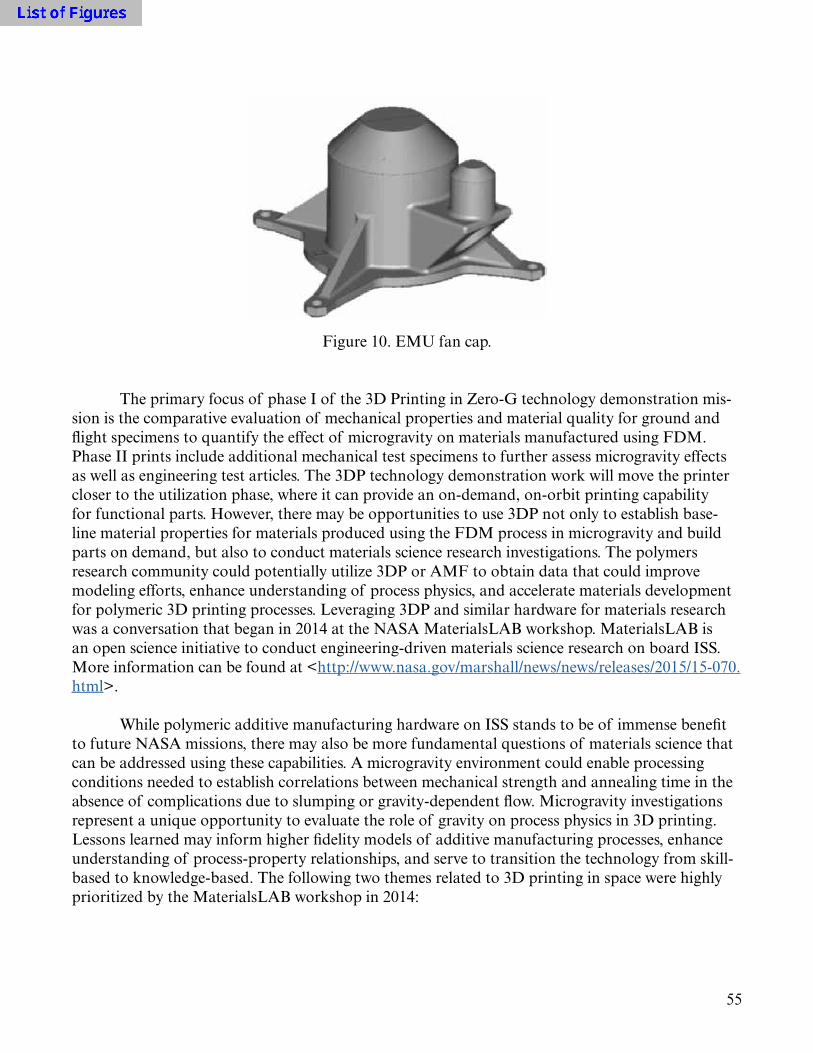
55
F10
Figure 10. EMU fan cap.
The primary focus of phase I of the 3D Printing in Zero-G technology demonstration mis-sion is the comparative evaluation of mechanical properties and material quality for ground and flight specimens to quantify the effect of microgravity on materials manufactured using FDM. Phase II prints include additional mechanical test specimens to further assess microgravity effects as well as engineering test articles. The 3DP technology demonstration work will move the printer closer to the utilization phase, where it can provide an on-demand, on-orbit printing capability for functional parts. However, there may be opportunities to use 3DP not only to establish base-line material properties for materials produced using the FDM process in microgravity and build parts on demand, but also to conduct materials science research investigations. The polymers research community could potentially utilize 3DP or AMF to obtain data that could improve modeling efforts, enhance understanding of process physics, and accelerate materials development for polymeric 3D printing processes. Leveraging 3DP and similar hardware for materials research was a conversation that began in 2014 at the NASA MaterialsLAB workshop. MaterialsLAB is an open science initiative to conduct engineering-driven materials science research on board ISS. More information can be found at <http://www.nasa.gov/marshall/news/news/releases/2015/15-070.html>.
While polymeric additive manufacturing hardware on ISS stands to be of immense benefit to future NASA missions, there may also be more fundamental questions of materials science that can be addressed using these capabilities. A microgravity environment could enable processing conditions needed to establish correlations between mechanical strength and annealing time in the absence of complications due to slumping or gravity-dependent flow. Microgravity investigations represent a unique opportunity to evaluate the role of gravity on process physics in 3D printing. Lessons learned may inform higher fidelity models of additive manufacturing processes, enhance understanding of process-property relationships, and serve to transition the technology from skill-based to knowledge-based. The following two themes related to 3D printing in space were highly prioritized by the MaterialsLAB workshop in 2014:
56
(1) Thermophysical property measurement of polymeric additively manufactured materi-als—Accurate thermophysical property data will improve the fidelity of predictive models and reduce bias and uncertainty in simulations of polymeric additive manufacturing processes.
(2) Benchmarking—Printing materials and test specimens on ISS at limits not possible in a terrestrial environment (e.g., filamentous of high-aspect ratio structures).
Shortly after the completion of this TIM, a request for information (RFI) was issued to solicit ideas (on research investigations using 3DP) from members of the materials science research community who participated in the 2014 MaterialsLAB workshop. This soliticitation does not rep-resent any commitment on the part of NASA, but will be used to prepare a use case for the printer related to materials science investigations.
The culmination of the materials characterization and development work for 3DP is the utilization catalog, a library of preapproved part files that can be printed on demand. Parts in the catalog have completed V&V activities, satisfied NASA standards and requirements for space flight hardware, and have been certified for use in their intended application. An entry for a part in the catalog may include the following information: unique part name and identification number; a picture of the part and a CAD rendering; a description of the part, its function, and other parts it interfaces with; approved printers and feedstocks for making the part; guidelines for use, includ-ing loads, environments, and restrictions on part life; and a link to the G-code file that the printer would use to print the part.
To become part of the utilization catalog, a part must be certified. Certification is the affir-mation by the program, project, or other reviewing authority that the V&V process is complete and has adequately assured the design and as-built part meet the established requirements to safely and reliably complete the intended mission. The certification process for ISM and 3DP has yet to be fully defined, but it will likely be similar to the process for additive manufacturing of metallics (dis-cussed in TIM session III). The first step toward certification is the system definition and require-ments phase. This includes identification and/or development of program requirements, NASA standards, and component specifications that the design and the as-built part must satisfy. A vali-dated part is one whose design meets all the requirements defined in this initial step. Verification of the design (distinct from verification of the as-built part) is accomplished through testing, analysis, and design review or some combination of these activities. Similarly, verification of the as-built part may be based on inspection, testing, and review. Certification thus represents the acceptance of verification events/activities.
It is important to note that in this framework certification has two parts: design certification and as-built part certification. Design certification is a stand-alone event that typically occurs at the completion of the design process, but prior to fabrication of the part. Design certification may also follow a significant change to the design, understanding of environments, or system behavior. Certification of the part is intended to ensure that the fabricated component fully meets the intent of the certified design definition at the time of flight/use.

57
Design certification is affirmed relative to a defined set of requirements; therefore, design certification requires that system definitions be established with all proper supporting requirements defined. Functional parts produced using ISM capabilities should satisfy governing NASA mate-rials and processes standards for spaceflight hardware. The working definition of design in this context refers to all information needed to define the part and its role in a component or subsystem such that it can be verified against all the applicable requirements. This information set includes, but is not limited to, the following (much of this information will be included in the entry for a part in the utilization catalog):
• Geometry definition through drawings and/or CAD models, dimensional tolerances, etc.• Materials and process specifications and controls.• Inspection requirements, including methods and acceptance criteria.• Dimensional, NDE, cleanliness, etc.• Required controls for cleaning, handling, storage, environmental protection, etc.• ‘First article’ evaluations, design qualification testing, part acceptance testing, etc.• Assessments of part performance, structural and otherwise, both analytical and experimental.
The certified design is the baseline to which as-built hardware is compared for verification and certification. Once a part has been produced, part verification may occur through inspection, testing, and materials and processes controls. For standard as-built hardware verification, these activities must demonstrate that the as-manufactured part is compliant with the certified design. When parts have discrepancies, NASA uses a material review board (MRB) approach to assess dis-crepancies in as-built parts relative to the certified design. The outcome of an MRB is acceptance, corrective actions, or rejection of the part.
For ISM, part verification activities are severely limited by inspection capabilities available on orbit. For instance, verification of a terrestrially produced part would likely include structured light scanning to verify dimensional complicance with the certified design and CT scanning to verify acceptable material quality/consolidation. This is not possible for parts printed on ISS unless they are downmassed to Earth. Thus it is expected that verification activities for ISM, which have yet to be fully defined, may rely on more indirect methods (i.e., key dimensional measurements with calipers, visual inspection, and assessment of in situ build information). The approach to part certi-fication for ISM may take a dual approach, with stringent verification activities for parts printed on the ground using flight-like units to certify the part for inclusion in the utilization catalog, followed by more relaxed verification activities for the part (driven by constraints on resources and crew time) when it is produced on orbit. If materials produced using FDM are not impacted by micro-gravity, the assumption can be made that certification of a part terrestrially also certifies the part produced on orbit.
A rational approach to certification is critical to enabling utilization of 3DP and future AMFs. The V&V process is not one-size-fits-all and it is recommended that verification require-ments and activities be scaled appropriate to risk. For instance, a part with a high consequence of failure (i.e., failure would result in loss of life or mission) should require more stringent V&V activities than a part with a high structural margin, a part that is part of a redundant structure, or a part that has a low consequence and low probability of failure. The part criticality classification

58
scheme developed for additive manufacturing of metallics at MSFC can serve as a guide for devel-oping the path to certification for parts that will become part of the 3DP utilization catalog. The goal of the classification approach is to inform flexible, tailorable, and rational approaches to V&V that enable early use of the technology while also controlling risk.
6.3 Strength Improvement of 3D Printed Plastic Parts
As the 3DP capability on ISS evolves from the implementation and testing phase toward utilization, the ISM team anticipates that ABS materials with higher strength and performance capabilities than those currently attainable with FDM processes (either terrestrially or in micro-gravity) will be required for some applications. Irrespective of the process used to manufacture them, plastics will almost certainly always have significantly lower strengths than aerospace-grade metallic or composite materials. However, strengthening ABS materials produced by FDM can bring their properties closer to those associated with injection molded ABS, thereby making them a more attractive material for use in some applications and building confidence in materials produced using FDM among the design community. Dr. Raj Kaul from MSFC presented his work on in situ and postprocessing manufacturing techniques that could potentially bridge the material property gap between ABS produced by FDM and ABS manufactured using conventional tech-niques (i.e., injection molding).
Three-dimensional printed ABS materials are lower in strength than those fabricated by conventional methods (injection molding). This discrepancy can be attributed to the layered struc-ture created by the 3D printing process, which creates inherent anisotropy in the manufactured material. The purpose of Dr. Kaul’s effort is to develop a post-3D printing treatment process to improve the mechanical properties of ABS produced via FDM. Dr. Kaul has also conducted inves-tigations on nano- and microfiber reinforcement of ABS feedstock, also with the goal of mechani-cal property enhancement.
The postprocess heat treatment for 3D printed ABS has to be such that it does not drasti-cally alter the characteristic dimensions of the part. Preliminary test results showed that ABS plastic has a critical temperature; when heat treatment processes occur below this temperature, the dimensions of the part are not affected. Heat treatment has the overall effect of eliminating pores and homogenizing the material. The homogenization effect is evident from fracture surface morphologies examined pre- and post-heat treatment (fig. 11). A fully consolidated isotropic part (which describes the condition of the material post-heat treatment) performs better than a less dense, anisotropic material (characteristics of the as-manufactured material). Mechanical test results from this investigation showed a 15% to 20% increase in tensile strength of the 3D printed material after it underwent the optimized heat treatment regime.

59
(a) (b)
F11
Figure 11. Impact of heat treatment on fracture surface morphologies for ABS material in (a) as-built condition and (b) following heat treatment.
The strength of ABS plastics can also be enhanced through the inclusion of reinforcements in the form of nano- or microfibers. An in-house process was developed at MSFC to incorporate whiskers or nanotube fiber reinforcements into ABS plastic. Filaments were subsequently drawn from the reinforced plastic pallets for 3D printing. The resulting composite filaments were mechan-ically tested in tension. The test results indicated strength improvements in the range of 25% to 30%, with the degree of improvement correlated with the volume fraction of fibers in ABS. The effort is ongoing to develop optimized parameters for 3D printing using reinforced ABS as feedstock.
6.4 Summary and Discussion
The topics addressed in this session represent the culmination of materials characterization activities. The ultimate goal of the material property database development work for ISM is to pro-vide input for designers that will enable them to use ISM capabilities to manufacture engineering test articles and eventually functional parts. Negotiating the materials development triangle from the base of the pyramid (building the material property database through mechanical coupon test-ing) to the apex (utilization, where 3DP and other facilities can be used to print parts on demand) requires close collaboration with analysts to anchor material behavior predicted using structural models (with material property data collected through fundamental characterization testing as inputs) with results from structural testing of elements, components, subsystems, etc. Defining and executing these anchoring activities in a collaborative manner is critical for enabling utilization; engagement with analysts in undertaking this aspect of ISM material development work is one of the key outcomes of the TIM. This is also necessary work for verification, validation, and certifica-tion, where the primary challenge is the lack of understanding of failure modes. Testing is needed to anchor models and develop tools that can bridge the gap between material property develop-ment activities and analysis.
It is difficult to infuse new manufacturing techniques into the design community, especially when the technology is nascent for a particular application and any failure, even in the develop-ment phase, stands to tarnish it (and, by proxy, the program the technology is being leveraged for). The historical example of this is the X-33 composite tank, which failed during a pressurized proof test in the early 2000s. Thermal cycling of the tank during this test induced microcracking,

60
which allowed fuel to permeate the composite and compromise the structural elements. For years, the attitude of the aviation and aerospace communities towards composites was skewed by this high-profile failure. It was not until advances in composite manufacturing made by the aviation sector enabled the use of composites in commercial airlines such as the Dreamliner that the idea of composite materials for cryogenic propellant tanks began to be reconsidered. The recent success of the composite cryogenic tank demonstration article, built by Boeing for NASA, demonstrates that these materials have immense potential for aerospace.
To protect ISM and its portfolio of technologies from facing a setback like composites for cryogenic fuel tanks suffered, where a moratorium on development due to a test failure severely impeded technology development in the space sector, the ISM team seeks to conduct materials characterization activities in parallel with design and testing to mitigate some of the risk associ-ated with implementation of these technologies into flight hardware upfront. The AMDE project, discussed in this portion of the TIM, can serve as a model for this engineering philosophy.
Another key activity for the ISM team is verification, validation, and certification. The chal-lenges faced in developing a rational path to certification and executing V&V activities for 3DP are similar to those confronted in additive manufacturing of metallics. How do we verify that a design is good and will perform in its intended application/use? How do we verify that an as-built part meets requirements and design intent (this is particularly difficult for parts manufactured on ISS due to limited on-orbit inspection capabilities and constraints on crew time)? The ISM team is cur-rently examining the approaches to V&V and certification for additive manufacturing of metallics as a guide for developing the certification path for ISM parts as well as standard and nonstandard methods of verification. Nonstandard methods are appropriate when traditional methods fall short (e.g., the part has internal passages that cannot be inspected). Nontraditional verification methods may rely extensively on analysis, overtesting, or testing with damage (i.e., testing the design well beyond the loads, life, etc. it will experience in its intended use environment). If it is determined that microgravity does not impact the FDM process, this greatly simplifies V&V activities since we can assume that the material properties and performance of the parts manufactured on Earth are commensurate with those manufactured in a microgravity environment. Another challenge to this work is developing a scaleable V&V/certification process based on risk. Most ISM parts have low consequences of failure, so the stringent V&V activities associated with a metallic additive manu-factured part whose end use is in engine turbomachinery, for example, will not be required.
The greatest barrier to utilization of additive manufacturing in general is that our ability to build and test additive manufacturing parts sometimes exceeds our ability to model. To this end, the ISM team is collaborating with the design and analysis groups at MSFC to develop activities that will help anchor the material property database and develop the tools we need to analyze parts built using this capability. There is also collaborative work underway on modeling the FDM pro-cess at smaller length scales, and the team has identified the thermophysical properties that need to be characterized in order to facilitate this. These tasks will help us develop a predictive capability for 3DP that will ultimately enable use of the hardware by the projects and programs it stands to benefit.
The vision for the 3DP hardware is a scenario where the printer is able to print parts reliably and on demand to support ISS operations. The materials characterization tasks identified through

61
the TIM will make great strides toward revising engineering mental models about when a technol-ogy can be implemented, accelerating acceptance of 3DP/ISM among the design community and getting designers to think of 3DP as simply another manufacturing capability available to support fabrication of their hardware (albeit one that happens to be located 200 miles above the Earth).
Another topic addressed in this session of the TIM was that 3DP is in some ways a piece of hardware in search of a ‘killer app.’ A key question posed was: what is the component that could be printed using this capability that could potentially save a mission? Discussions are ongoing with potential stakeholders to identify candidate parts that could utilize 3DP’s fabrication capabilities, but we are particularly interested in those that are critical to the functioning of space station sys-tems and also have materials and geometries compatible with the 3DP unit. This thought experi-ment, however, goes beyond just ISS, as 3DP is a crucial technology for any long-duration mission where cargo resupply is not an option.
The ISM team understands that 3DP is not a panacea for manufacturing in the space envi-ronment, as there are, of course, process limitations and upper limits on component size. Ulti-mately, 3DP will be part of a suite of technologies—from welding to additive manufacturing of metallics to ISRU processes—that will enable us to truly live and work in space. 3DP represents the first manufacturing capability on board the ISS and it is humanity’s first small step toward reducing reliance on Earth-based platforms, transforming launch architectures, and enabling long-duration space exploration missions with enhanced crew safety.

62

63
7. FINAL SUMMARY AND OUTCOMES
The TIM on development of baseline material properties for ISM (specifically focused on in-space additive manufacturing of polymeric materials) had over 60 participants from MSFC, other NASA Centers, and external organizations (government, industry, and academia). The over-all objective of the TIM was to leverage shared experiences and collective knowledge in advanced manufacturing and materials development to craft a plan for the development of characteristic material properties for ISM (specifically 3DP) that will support design, analysis/modeling, and standards development/certification activities. The TIM consisted of an overview session on the ISM program followed by four focused sessions on key aspects of materials characterization. Ses-sion I on identifying critical material properties for ISM design and analysis examined properties needed for structural modeling, design considerations and guidelines for additive manufacturing, and characterization of friction and wear properties of additively manufactured parts. Session II, materials testing for ISM, considered test plans for additively manufactured metallic parts and techniques from composites used to characterize anisotropy. The test plan for the phase I prints from the 3D Printing in Zero-G technology demonstration mission was also presented. Session III, development of baseline material property design values for ISM, evaluated statistical methodolo-gies for material allowables development. Other presentations in this session included a case study on a phased approach to allowable generation for FSW and a look at the certification methodology for additively manufactured metallic parts. In session IV on printer capabilities and use scenarios, engineers from the ISM team gave a detailed overview of the 3DP and AMF hardware as well as the utilization catalog for parts that can be printed on ISS. A representative from the AMDE at MSFC gave a summary of development work to date as an example of how (1) additive manufac-turing capabilities can be successfully leveraged and integrated into space hardware and (2) materi-als characterization and design/testing/analysis can take place in parallel. Since as-built ABS plastic parts have strengths that are much less than metallic or composite parts, Dr. Raj Kaul spoke on work at MSFC to postprocess ABS parts printed using FDM or including additives in the feed-stock to strengthen the materials and broaden their potential applications.
Overall, the TIM achieved the goals of helping to define materials characterization activi-ties, accelerated acceptance and adoption of ISM capabilities among the NASA community, and established opportunities and avenues for further collaboration in this research area both within NASA and externally. The TIM succeeded in identifying properties that need to be characterized for design and analysis, determining the tests that are needed to obtain these properties, develop-ing statistical approaches to establish characteristic design values, identifying and/or developing use scenarios for 3DP and/or AMF, and providing a broad understanding of V&V activities that will be needed to certify parts for printing on demand. Additional details on TIM outcomes and follow-on activities are summarized as follows:

64
• Designers and analysts offered feedback on material properties and other pertinent design con-siderations that must be characterized in order to fully utilize ISM capabilities.
– A list of first tier/higher priority properties and second tier/lower priority properties evolved from this discussion.
– The ISM team is currently working with the structural analysis group at MSFC to define analy-sis correlation activities that will anchor material properties developed in materials character-ization with predictions from models and instrumented structural tests.
– The ISM team is also working with a physics-based modeling group at Ames Research Center to develop predictive models of the FDM process at the microscale. The first step in this work is to characterize thermophysical properties for ABS plastic produced using FDM that can serve as inputs for microstructural models. This effort is complementary to the marcroscale modeling activities being undertaken at MSFC.
• Once properties have been identified, defining the type of coupon tests and the standards to test to is critical as it represents the primary means of deriving data that will enable an analysis capa-bility and define design requirements. The material produced via FDM is an anisotropic plastic. Since we do not have a composite material, testing to composite standards (without modifica-tion) is not appropriate. ISM will primarily use ASTM standards for plastics to guide coupon and test procedure development. The ISM team is using the NIST document, “Materials Testing Standards for Additive Manufacturing of Polymer Materials: State of the Art and Standards Applicability,” as a key reference in standards identification and modification.21 Documentation of test methods and consistency between tests are also essential. Based on feedback from the TIM, the ISM project will no longer test to characterize flexural strengths and flexural moduli of parts since these are not relevant properties for near-term design or analysis.
• A phased materials characterization approach has been developed to establish baseline/charac-teristic properties for materials produced via the FDM process that can subsequently be used for design and analysis. The proposed approach, which utilizes DOE techniques, is similar to meth-odologies developed for material property development in welding and additive manufacturing of metallics. The phase I DOE is designed to assess sensitivities of material properties of ABS material produced using FDM to manufacturing process variables (printer, feedstock, filament layup, build orientation, and test temperature). Based on the results of the phase I work, a more focused phase II DOE will be developed to define characteristic material properties based on statistical tolerance regions. Follow-on DOEs can be used to further characterize the impact of printers/printer capabilities and feedstock (lot-to-lot variability, feedstock color, etc.) on material properties.
• The ISM team is engaging key stakeholders/groups at NASA to identify candidate parts from their systems and/or projects that are within the printing capability of 3DP and/or AMF. An informal RFI was disseminated to a focused contingent of the materials science community (primarily participants in a previous NASA workshop on development of microgravity materials science payload) to assess potential materials science investigations that could utilize 3DP and/or AMF hardware.

65
• The ISM team will continue work with the MAPTIS database team to develop a plan for even-tual transfer of the ground-based materials characterization data for FDM ABS as well as test results from the in-space specimens manufactured as part of the 3D Printing in Zero-G technol-ogy demonstration mission into MAPTIS.
A second TIM focused specifically on the 3D Printing in Zero-G technology demonstration mission was held at MSFC on December 2 and 3, 2015. At this meeting, the ISM team presented test results from this mission, including an extensive comparative evaluation of the ground and flight specimens to assess microgravity effects on the printing process. The second TIM fostered continued interaction between (1) the materials engineering and design/analysis communities and (2) NASA and external partners with expertise in this field. This sustained engagement is critical to developing the suite of design value properties that are needed to institutionalize current capabili-ties and advance manufacturing in space.

66
REFERENCES
1. CMH-17, “Composite Materials Handbook,” SAE International, Warrendale, PA, 2012.
2. “Fracture Control Requirements for Spaceflight Hardware,” NASA-STD-5019, NASA Head-quarters, Washington, DC, 44 pp., July 2008.
3. ASTM G77, “Standard Test Method for Ranking Resistance of Materials to Sliding Wear Using Block-on-Ring Wear Test,” ASTM International, West Conshohocken, PA, 2010.
4. ASTM E8, “Standard Test Methods for Tension Testing of Metallic Materials,” ASTM Inter-national, West Conshohocken, PA, 2009.
5. ASTM E466, “Standard Practice for Conducting Force Controlled Constant Amplitude Axial Fatigue Tests of Metallic Materials,” ASTM International, West Conshohocken, PA, 2015.
6. ASTM E606, “Standard Test Method for Strain-Controlled Fatigue Testing,” ASTM Interna-tional, West Conshohocken, PA, 2012.
7. ASTM E1820, “Standard Test Method for Measurement of Fracture Toughness,” ASTM International, West Conshohocken, PA, 2015.
8. ASTM E647, “Standard Test Method for Measurement of Fatigue Crack Growth Rates,” ASTM International, West Conshohocken, PA, 2015.
9. ASTM E139, “Standard Test Methods for Conducting Creep, Creep-Rupture, and Stress- Rupture Tests of Metallic Materials,” ASTM International, West Conshohocken, PA, 2011.
10. ASTM G142, “Standard Test Method for Determination of Susceptibility of Metals to Embrittlement in Hydrogen Containing Environments at High Pressure, High Temperature, or Both,” ASTM International, West Conshohocken, PA, 2011.
11. ASTM D638, “Standard Test Method for Tensile Properties of Plastics,” ASTM International, West Conshohocken, PA, 2014.
12. ASTM D695, “Standard Test Method for Compressive Properties of Rigid Plastics,” ASTM International, West Conshohocken, PA, 2015.
13. ASTM D790, “Standard Test Methods for Flexural Properties of Unreinforced and Rein-forced Plastics and Electrical Insulating Materials,” ASTM International, West Conshohocken, PA, 2015.
67
14. ASTM D3019, “Standard Specification for Lap Cement with Asphalt Roll Roofing, Non-Fibered, and Non-Asbestos-Fibered,” ASTM International, West Conshohocken, PA, 2008.
15. ASTM D3410, “Standard Test Method for Compressive Properties of Polymer Matrix Com-posite Materials with Unsupported Gage Section by Shear Loading,” ASTM International, West Conshohocken, PA, 2008.
16. ASTM D6641, “Standard Test Method for Compressive Properties of Polymer Matrix Com-posite Materials Using a Combined Loading Compression (CLC) Test Fixture,” ASTM Inter-national, West Conshohocken, PA, 2014.
17. ASTM D5467, “Standard Test Method for Compressive Properties of Unidirectional Polymer Matrix Composites Using a Sandwich Beam,” ASTM International, West Conshohocken, PA, 2010.
18. ASTM D1737, “Method of Test for Elongation of Attached Organic Coatings with Cylindri-cal Mandrel Apparatus,” ASTM International, West Conshohocken, PA, 1985.
19. ASTM D3518, “Standard Test Method for In-Plane Shear Response of Polymer Matrix Composite Materials by Tensile Test of a ±45° Laminate,” ASTM International, West Con-shohocken, PA, 2013.
20. ASTM D7078, “Standard Test Method for Shear Properties of Composite Materials by V-Notched Rail Shear Method,” ASTM International, West Conshohocken, PA, 2012.
21. Foster, A.M.: “Materials Testing for Additive Manufacturing for Polymer Materials: State of the Art and Standards Applicability,” National Institute of Standards and Technology, Gaith-ersburg, MD, 54 pp., May 2015.
22. “Standard Materials and Processes Requirements for Spacecraft,” NASA-STD-6016, NASA Headquarters, Washington, DC, 67 pp., July 2008.
23. MMPDS, “Metallic Materials Properties Development and Standardization,” Battelle Memo-rial Institute, Columbus, OH, 2015.
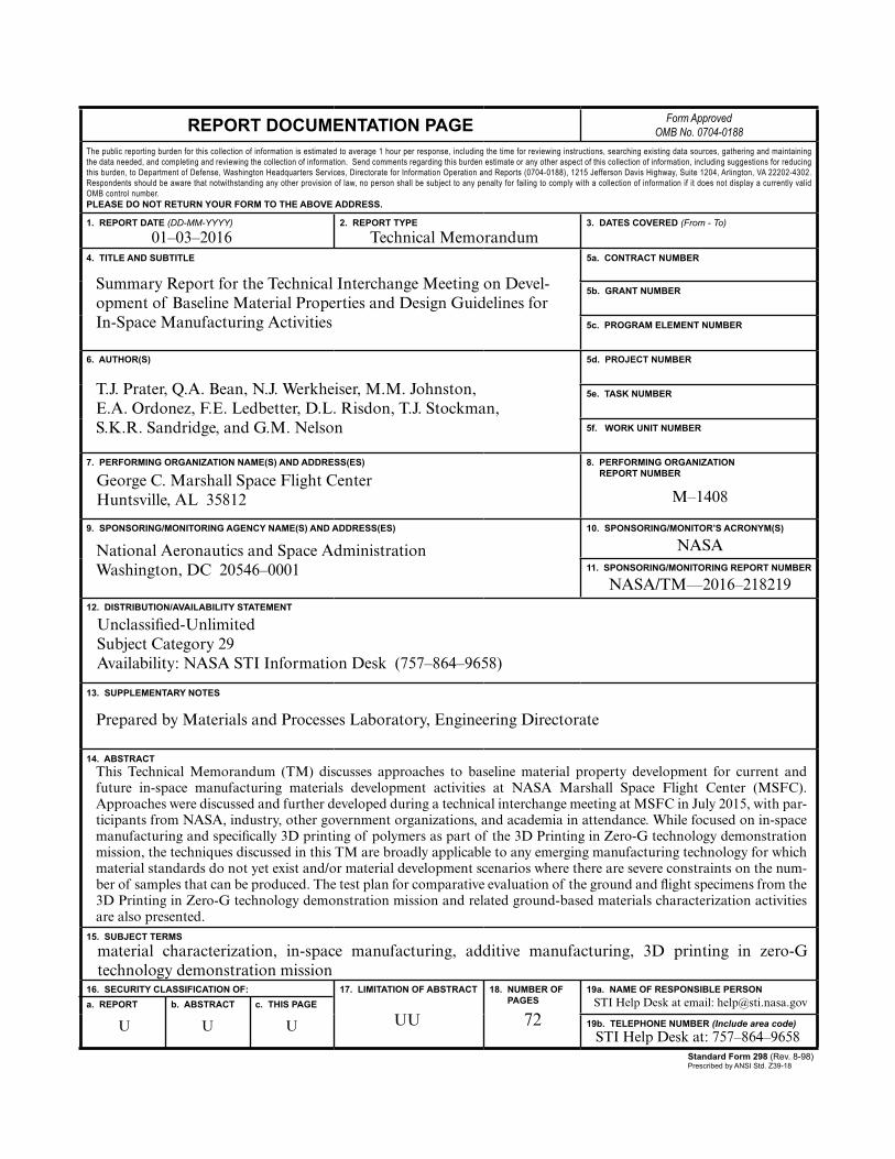
68
REPORT DOCUMENTATION PAGE Form ApprovedOMB No. 0704-0188
The public reporting burden for this collection of information is estimated to average 1 hour per response, including the time for reviewing instructions, searching existing data sources, gathering and maintaining the data needed, and completing and reviewing the collection of information. Send comments regarding this burden estimate or any other aspect of this collection of information, including suggestions for reducing this burden, to Department of Defense, Washington Headquarters Services, Directorate for Information Operation and Reports (0704-0188), 1215 Jefferson Davis Highway, Suite 1204, Arlington, VA 22202-4302. Respondents should be aware that notwithstanding any other provision of law, no person shall be subject to any penalty for failing to comply with a collection of information if it does not display a currently valid OMB control number.PLEASE DO NOT RETURN YOUR FORM TO THE ABOVE ADDRESS.
1. REPORT DATE (DD-MM-YYYY) 2. REPORT TYPE 3. DATES COVERED (From - To)
4. TITLE AND SUBTITLE 5a. CONTRACT NUMBER
5b. GRANT NUMBER
5c. PROGRAM ELEMENT NUMBER
6. AUTHOR(S) 5d. PROJECT NUMBER
5e. TASK NUMBER
5f. WORK UNIT NUMBER
7. PERFORMING ORGANIZATION NAME(S) AND ADDRESS(ES) 8. PERFORMING ORGANIZATION REPORT NUMBER
9. SPONSORING/MONITORING AGENCY NAME(S) AND ADDRESS(ES) 10. SPONSORING/MONITOR’S ACRONYM(S)
11. SPONSORING/MONITORING REPORT NUMBER
12. DISTRIBUTION/AVAILABILITY STATEMENT
13. SUPPLEMENTARY NOTES
14. ABSTRACT
15. SUBJECT TERMS
16. SECURITY CLASSIFICATION OF:a. REPORT b. ABSTRACT c. THIS PAGE
17. LIMITATION OF ABSTRACT 18. NUMBER OF PAGES
19a. NAME OF RESPONSIBLE PERSON
19b. TELEPHONE NUMBER (Include area code)
Standard Form 298 (Rev. 8-98)Prescribed by ANSI Std. Z39-18
Summary Report for the Technical Interchange Meeting on Devel-opment of Baseline Material Properties and Design Guidelines for In-Space Manufacturing Activities
T.J. Prater, Q.A. Bean, N.J. Werkheiser, M.M. Johnston, E.A. Ordonez, F.E. Ledbetter, D.L. Risdon, T.J. Stockman, S.K.R. Sandridge, and G.M. Nelson
George C. Marshall Space Flight CenterHuntsville, AL 35812
National Aeronautics and Space AdministrationWashington, DC 20546–0001
Unclassified-UnlimitedSubject Category 29Availability: NASA STI Information Desk (757–864–9658)
Prepared by Materials and Processes Laboratory, Engineering Directorate
M–1408
Technical Memorandum
NASA/TM—2016–218219
material characterization, in-space manufacturing, additive manufacturing, 3D printing in zero-G technology demonstration mission
01–03–2016
UU 72
NASA
U U U
This Technical Memorandum (TM) discusses approaches to baseline material property development for current and future in-space manufacturing materials development activities at NASA Marshall Space Flight Center (MSFC). Approaches were discussed and further developed during a technical interchange meeting at MSFC in July 2015, with par-ticipants from NASA, industry, other government organizations, and academia in attendance. While focused on in-space manufacturing and specifically 3D printing of polymers as part of the 3D Printing in Zero-G technology demonstration mission, the techniques discussed in this TM are broadly applicable to any emerging manufacturing technology for which material standards do not yet exist and/or material development scenarios where there are severe constraints on the num-ber of samples that can be produced. The test plan for comparative evaluation of the ground and flight specimens from the 3D Printing in Zero-G technology demonstration mission and related ground-based materials characterization activities are also presented.
STI Help Desk at email: [email protected]
STI Help Desk at: 757–864–9658


NASA/TM—2016–218219
Summary Report for the Technical Interchange Meeting on Development of Baseline Material Properties and Design Guidelines for In-Space Manufacturing ActivitiesT.J. Prater, Q.A. Bean, N.J. Werkheiser, M.M. Johnston, E.A. Ordonez, F.E. Ledbetter, D.L. Risdon, T.J. Stockman, S.K.R. Sandridge, and G.M. NelsonMarshall Space Flight Center, Huntsville, Alabama
March 2016
National Aeronautics andSpace AdministrationIS02George C. Marshall Space Flight CenterHuntsville, Alabama 35812