Summary of last time - OS3 · Summary of last time TCP congestion control phases Differences...
19
4/8/14 1 Part 1: Lecture 3 Beyond TCP Summary of last time TCP congestion control phases Differences between TCP stack implementations TCP state machine TCP • You discuss with your colleague next to you what are the limitation of TCP stacks and make a list of suggestions for improvement. Your list • Multicast support • Encryption • Multiple streams • Support for real-time applications • Optimization of fairness • …..
Transcript of Summary of last time - OS3 · Summary of last time TCP congestion control phases Differences...

4/8/14
1
Part 1: Lecture 3 Beyond TCP
Summary of last time
TCP congestion control phases�
Differences between TCP stack implementations�
TCP state machine�
TCP • You discuss with your
colleague next to you what are the limitation of TCP stacks and make a list of suggestions for improvement.
Your list • Multicast support • Encryption • Multiple streams • Support for real-time applications • Optimization of fairness • …..

4/8/14
2
Limitations of TCP According to RFC 4960 – Stream Control Transport Protocol: 1. Not everybody needs reliable data transfer and strict
order-of-transmission delivery of data.
2. Streams may force application to mark boundaries of messages or PUSH to get whole messages delivered.
3. TCP sockets have limited scope and don’t exploit nodes with multiple IP addresses for high available transfers.
4. Vulnerability to SYN attacks
SYN attack and SYN cookie
The Transmission Control Block (TCB) is a transport protocol data structure (actually a set of structures in many operations systems) that holds all the information about a connection.
TCB is encoded in sequence number and destroyed
plus cookie
TCB is recovered from the sequence number in the ACK segment
plus cookie
TCP Cookie Transactions (TCPCT)
Possible solutions Create completely new protocols.
Provide reliability on top of UDP. Further tweak/improve TCP.
SCTP
RFCs 4960 defines SCTP Stream Control Transmission Protocol

4/8/14
3
PSTN networks and protocols
• How do you setup a land line phone call?
SS7 is an out of band protocol that separates the voice path and the signaling path. It is possible to run SS7 over IP
networks, if one can: 1. Minimize end-to-end delay.
2. Guarantee short failover time in case of network failures
SCTP • Originally to be used in PSTN networks to carry SS7 (signaling
for telephone call setup and tear down ) over IP networks
• New features • Multi homing: increased resilience to network failures
• Multiple streams between endpoints
• Bundle of SCTP messages in one SCTP packet increase performance
• Security features against flooding and attacks.
SCTP Multi-homing Every IP address of the peer is considered as a path. All paths are continuously supervised and initially confirmed. One path, the so called primary path, is used for initial data transmission. In the case of (timer based) retransmissions an alternate path is used. Loadsharing is not part of RFC 4960 but subject of ongoing research.
SCTP data transfer • Multiplexing and demultiplexing for ordered delivery of
messages. • Only data sent within the same stream is delivered in sequence
relative to that stream. – This minimizes the impact of head of line blocking in case of
message loss.

4/8/14
4
SCTP message format
SCTP packet
SCTP Header
SCTP Chunk
SCTP Chunk
SCTP Chunk
Chunks may contain: 1. Control messages
a. Applicable to the association b. Applicable to one of the streams
2. Data exchanged on a stream Header:
1. Identifies the association 2. Contains security and verification details
SCTP header format
Verification tag
Checksum
Source port Destination port
16 bits 16 bits
• Source and destination ports are the same as for the other IP transport protocols; • The verification tag helps to protect from attacks; it allows to validate the sender.
SCTP chunk formats
Data
Chunk length Chunk type Chunk flags
Padding
• Data is interpreted according to the chunk type; • Chunks for the whole association or for individual streams are processed in order
SCTP chunk types • INIT, INIT-ACK, COOKIE-ECHO,
COOKIE-ACK. • HEARTBEAT, HEARTBEAT-ACK.
• DATA, SACK. • SHUTDOWN-, SHUTDOWN-ACK,
SHUTDOWNCOMPLETE. • ERROR, ABORT. • FORWARD-TSN. • ASCONF, ASCONF-ACK. • AUTH.
SCTP Association Initiator
SCTP Association Responder
INIT
INIT-ACK
COOKIE-ECHO
COOKIE-ACK
HEARTBEAT
HEARTBEAT-ACK
DATA
SACK
SHUTDOWN
SHUTDOWN-ACK SHUTDOWN-COMPLETE
4/8/14
5
SCTP data • The DATA chunk contains:
– TSN – Transmission Sequence Number – stream number – stream sequence number
16 bits 16 bits
Chunk length Chunk type = 0 Chunk flags TSN
Stream Sequence Number Stream Identifier Payload Protocol Identifier
User data
SCTP acks • Uses the selective acknowledgement idea from TCP:
– Cumulative TSN - transmission sequence number - plus gap acknowledgments blocks, for received data blocks .
35 36 39 38 37 40 47 46 45 43 44 42 41 51 50 48 49 34
Received Received Received
Missing Missing
Acknowledgement Cumulative TSN = 36
Start gap ack offset = 4
End gap ack offset = 9
Start gap ack offset = 12
Endgap ack offset = 14
Availability of implementations • Integrated in FreeBSD 7. • For Linux: Part of 2.6 kernels and even back-ported to 2.4
kernels. • Integrated in Solaris 10. • For BSD Unix, Linux, Solaris, Mac OS X, HP-UX and Windows:
sctplib (userland library). • Several commercial implementations. • Integrated in almost all SS7 nodes.
Want to know more? Want to play with it? http://www.sctp.de/ http://www.tdr.wiwi.uni-due.de/en/research/research-projects/sctp/#SCTP
Evolutionary approach • MPTCP – MultiPath TCP
• Tomorrow at 10.30am we will have a guest lecture from Benno Overeinder from NLNet labs on the topic.
• How do SCTP and MPTCP differ? • What are the pros and cons of the two approaches?

4/8/14
6
VoIP and videoconferencing
Voice over IP
• What’s the main advantage? Lower costs than on PSTN.
• Voice and multimedia sessions over the Internet/IP
Devices • Softphones
– a software program for making telephone calls over the Internet • VoIP phones
In the future: • Netbooks and smartphones, that support 5G handoff (IEEE
802.21) – Allow roaming between 802.11 networks and (3G) cellular
networks.
Real-time interactive applications PC to PC
PC to phone
Videoconference With webcam
4/8/14
7
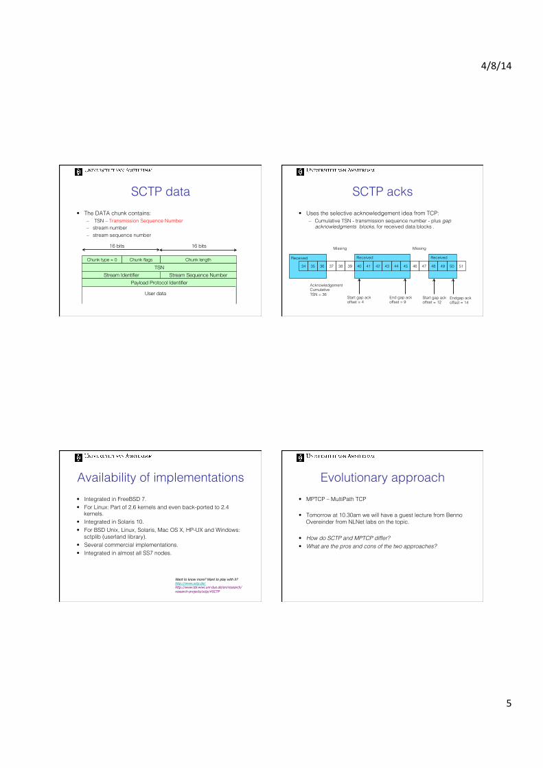
Video conferencing
• Reduced travel costs • Easier access to remote experts • More personal than a voice conference
• Sampling at constant rate
Which problems will you have? (How will transport the data over the network?)
Delay and jitter
Streaming stored video:
1. video recorded (e.g., 30 frames/sec)
2. video sent C
umul
ativ
e da
ta
streaming: at this time, client playing out early part of video, while server still sending later part of video
network delay (fixed in this
example) time
3. video received, played out at client (30 frames/sec)

4/8/14
8
How does delay occur?
A
B
packet needs to be transmitted
packets needs to wait its turn queueing
packet needs to travel on link
packet needs to be processed
Four sources of packet delays
dtrans: transmission delay: § L: packet length (bits) § R: link bandwidth (bps) § dtrans = L/R
dprop: propagation delay: § d: length of physical link § s: propagation speed in
medium (~2x10⁸ m/sec in optical fiber)
§ dprop = d/s dtrans and dprop very different
propagation
nodal processing queueing
d = dproc + dqueue + dtrans + dprop
A
B
transmission
Four sources of packet delay
dproc: nodal processing § check bit errors § determine output link § typically < msec
A
B
propagation
transmission
nodal processing queueing
dqueue: queueing delay § time waiting at output link for
transmission § depends on congestion level of
router
d = dproc + dqueue + dtrans + dprop
End-to-end delay
d = ( LRii
∑ +dis+Qi (t))
d1,R1 d2,R2 d3,R3 d4,R4

4/8/14
9
Q(t)
Delay (msec)
Frac
tion
of p
acke
ts
(PD
F)
Q(t) and playout buffers
Delay (msec)
Frac
tion
of p
acke
ts
(PD
F)
Max tolerated delay
Related to the size of the playout buffer at the receiving end
constant bit rate video transmission
Cum
ulat
ive
data
time
variable network delay
client video reception
constant bit rate video playout at client
client playout delay
buffe
red
vide
o
Streaming stored video: revisited
• client-side buffering and playout delay: compensate for network-added delay, delay jitter
Loss tolerance • delay loss: IP datagram arrives too late for playout at receiver
– delays: processing, queueing in network; end-system (sender, receiver) delays
– typical maximum tolerable delay: 150 ms
• network loss: IP datagram lost due to network congestion (router buffer overflow)
• loss tolerance: depending on voice encoding, losses concealed, packet loss rates between 1% and 10% can be tolerated.
4/8/14
10
Test Pause
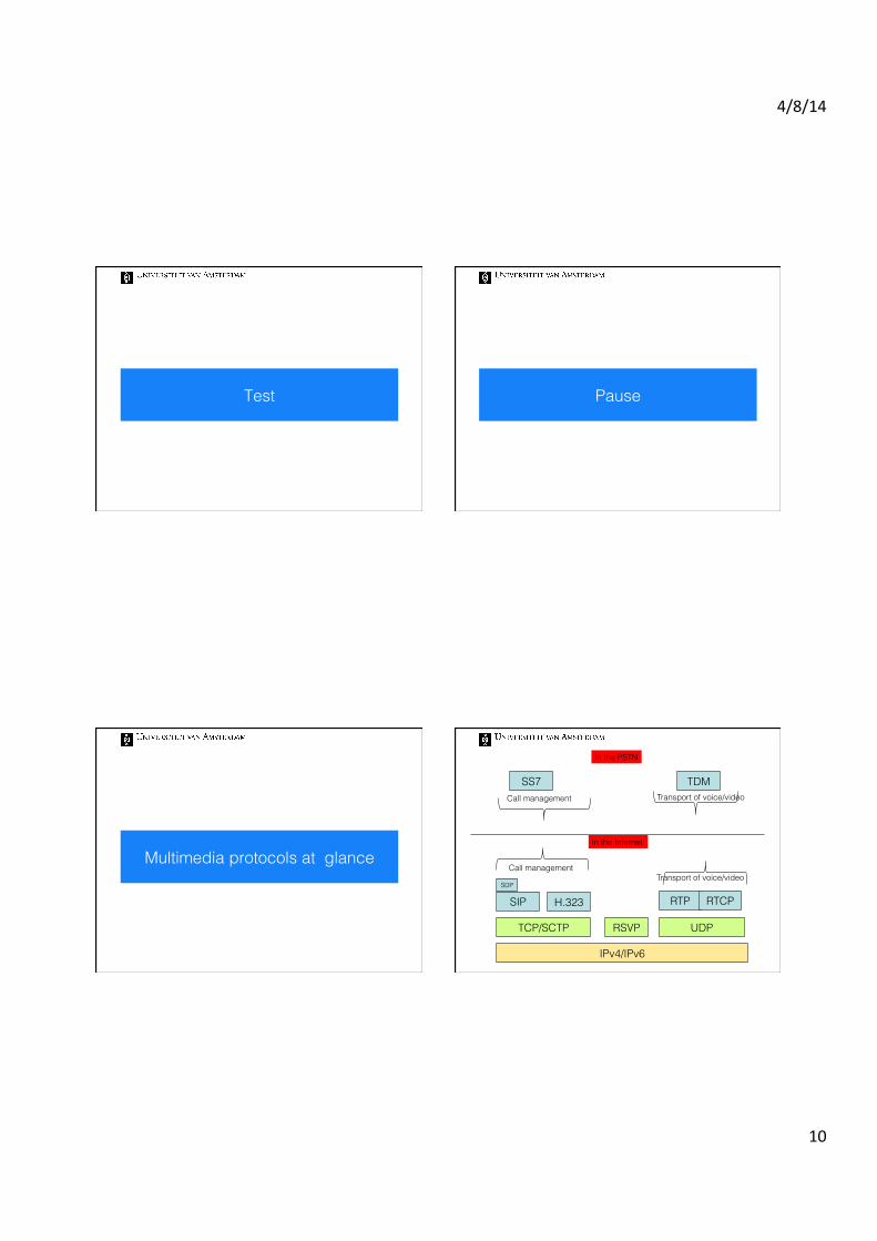
Multimedia protocols at glance
RTP RTCP
UDP
IPv4/IPv6
TCP/SCTP
SIP H.323 SDP
RSVP
Transport of voice/video
Call management
In the Internet
In the PSTN
SS7
Call management
Transport of voice/video
TDM

4/8/14
11
SIP versus RTP
• Initiate a session between two endpoints.
• Does not carry any voice or video data itself
• Transfer the traffic (voice or video)
RTP
Real-time Transport Protocol • RTP is a top-up transport protocol used for real-time
applications. Think of delivery of voice and video data: – Lightweight. One single message – Runs over another transport protocol – It support multicast.
• Accompanied by RTCP - Real-Time Transport Protocol: – A management protocol – Allows endpoints to exchange information about data flows – Used by RTP to determine how to tune its behavior
RTP features • Runs on top of UDP:
– no guarantee of reliability – no guarantee of packet ordering
• It uses timestamps, sequence numbering, and delivery confirmation for each packet sent.
• It supports error-correction schemes for increased robustness and basic security options for encrypting packets.
Header contains information related to the payload: the source, size, encoding type
Payload contains the real-time media
4/8/14
12
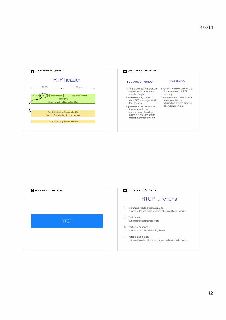
RTP header 16 bits 16 bits
Sequence number CC Payload type Timestamp
Synchronization Source Identifier
V P MX
First Contributing Source Identifier
Last Contributing Source Identifier
Second Contributing Source Identifier
Sequence number
A simple counter that starts at a random value when a session begins;
It increments by one with each RTP message sent in that session;
It provides a mechanism for the receiver to re-sequence packets that arrive out of order and to detect missing elements.
It carries the time index for the first sample of the RTP message.
The receiver can use this field to reassemble the information stream with the appropriate timing.
Timestamp
RTCP
RTCP functions 1. Integrated media synchronization
i.e. when video and audio are transmitted on different streams
2. QoS reports i.e. number of lost packets, jitters
3. Participation reports i.e. when a participant is leaving the call
4. Participation details i.e. information about the source, email address, sender names.
4/8/14
13
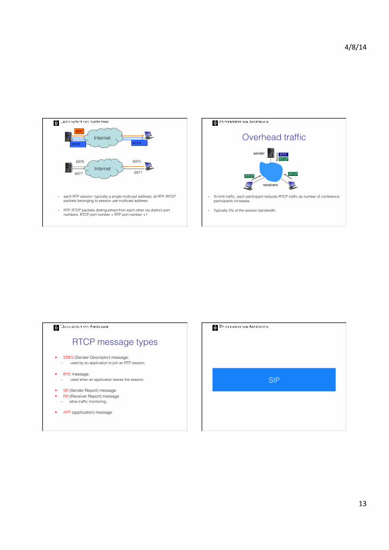
Internet RTP
RTCP RTCP
Internet 6970
6971
6976
6977
• each RTP session: typically a single multicast address; all RTP /RTCP packets belonging to session use multicast address
• RTP, RTCP packets distinguished from each other via distinct port numbers. RTCP port number = RTP port number +1
• To limit traffic, each participant reduces RTCP traffic as number of conference participants increases.
• Typically 5% of the session bandwidth.
RTCP RTP
RTCP RTCP
sender
receivers
Overhead traffic
RTCP message types • SDES (Sender Descriptor) message:
– used by an application to join an RTP session;
• BYE message: – used when an application leaves the session;
• SR (Sender Report) message • RR (Receiver Report) message
– allow traffic monitoring;
• APP (application) message
SIP

4/8/14
14
Session Initiation Protocol • SIP is described in RFC 3261 (2002) • An application layer protocol
– used instead of SS7 to initiate and terminate voice and video calls over IP networks (VoIP)
• It is independent of the underlying transport protocol – It can run on UDP, TCP, SCTP, RTP
TCP SCTP UDP
SIP RTCP RTP
Call Control Application Media Application
Session? • An exchange of data between an association of participants.
Participants: – may move between endpoints; – may be addressable by multiple names; – may communicate in several different media - sometimes
simultaneously
SIP creates an infrastructure of network hosts (called SIP proxy servers) to which user agents can send registrations, invitations to sessions, and other requests.
Internet endpoints (SIP user agents) discover one another and agree on a characterization of a session they would like to share.
SDP
SIP supports:
Session setup
Session management
User capabilities
User availability
User location
SIP identifiers • SIP uses URI – Universal Resource Identifiers - to identify the
communicating resource. • Two schemes are defined:
– Sip: – Sips:
• When secure transmission is requires, i.e. SIP messages are transported over TLS
sip:user:password@host:port sip:user:password@host:port;uri-parameters?headers
sip:[email protected];transport=tcp

4/8/14
15
SIP servers • Distributed functions across servers or consolidated in one
node:
– Proxy server • Intermediary program that acts as both a UA (User Agent) server and
UA client to make requests on behalf of other UA clients.
– Location server – Redirect server – Registrar server
Direct SIP call
SIP call with proxy SIP messages • Text based, with syntax similar to HTTP
SIP request!
SIP response!
INVITE, ACK, BYE, CANCEL, OPTIONS, REGISTER, PRACK, SUBSCRIBE, NOTIFY, PUBLISH, INFO, REFER, MESSAGE, UPDATE
1xx—Informational Responses 2xx—Successful Responses 3xx—Redirection Responses 4xx—Client Failure Responses 5xx—Server Failure Responses 6xx—Global Failure Responses
4/8/14
16
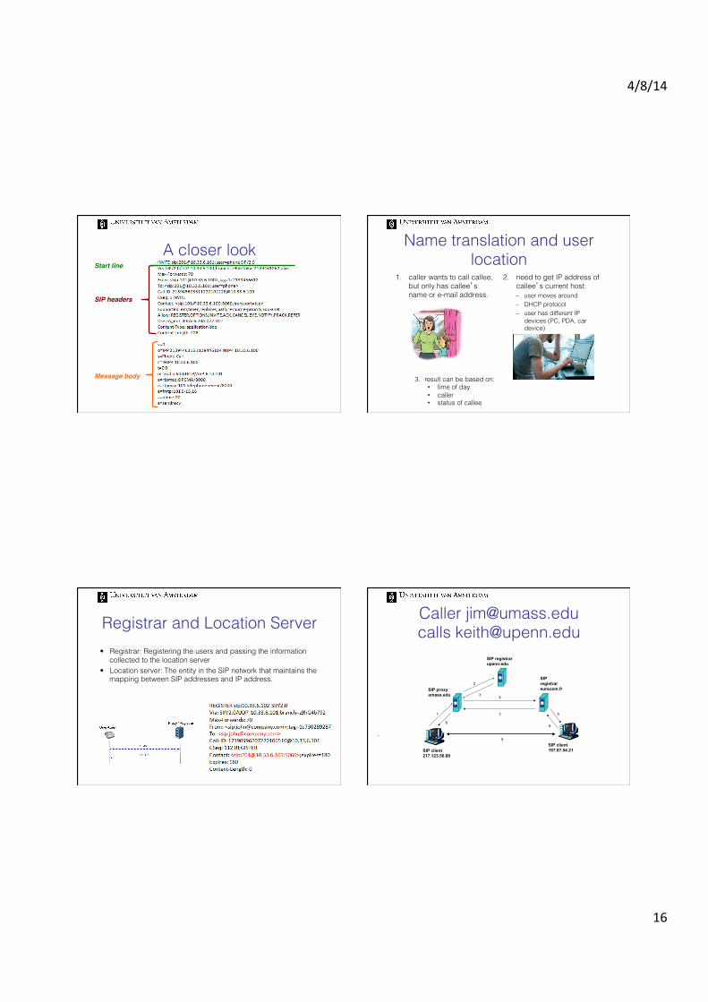
A closer look
SIP headers!
Message body!
Start line!
Name translation and user location
1. caller wants to call callee, but only has callee’s name or e-mail address.
2. need to get IP address of callee’s current host: – user moves around – DHCP protocol – user has different IP
devices (PC, PDA, car device)
3. result can be based on: • time of day • caller • status of callee
Registrar and Location Server • Registrar: Registering the users and passing the information
collected to the location server • Location server: The entity in the SIP network that maintains the
mapping between SIP addresses and IP address.
Caller [email protected] calls [email protected]
.
SIP client217.123.56.89
SIP client197.87.54.21
SIP proxyumass.edu
SIP registrarupenn.edu
SIPregistrareurecom.fr
1
2
3 4
5
6
7
8
9

4/8/14
17
H.323
H.323 history H.323 is another signaling protocol for real-time, interactive applications.
• 1996: ITU-T1 published Version 1 of Recommendation H.323 in “Visual Telephone Systems and Equipment for LANs which provide a non-guaranteed Quality of Service”
– not designed for the Internet! – only local calls, small number of users!
• 2009: current version – Operates well on WANs – Widely adopted also in large installations
H.323 protocol stack H.323 components
IP network
Terminal
Terminal Gatekeeper MCU
Gateway

4/8/14
18
A Terminal is an endpoint which provides for real-time, two-way communications with another H.323 terminal, GW, or MCU. This communication consists of speech only, speech and data, speech and video, or speech, data and video
The MCU (Multipoint Control Unit) consists of: 1. a mandatory Multipoint
Controller (MC) for call signaling, conference control
2. an optional Multipoint Processor (MP) switching/mixing of media stream
A Gateway provides for realtime, two-way communications between terminals belonging to networks with different protocol stacks
The Gatekeeper provides address translation and controls access to the network resources for H.323 terminals, GWs and MCUs
H.323 zones • Endpoints do register themselves at a GK
• All H.323 endpoints registered to a single GK build an H.323 zone:
– H.323 zones are independent of physical network topology – Each zone has only one GK (exception: Alternate GKs)
Gatekeeper functionalities 1. Address Translation
Translates H.323 IDs (such as [email protected]) and E.164 numbers (0031205257533) to endpoint IP addresses
2. Admission control / bandwidth control Every call within the zone gets authorized by the GK Admission requests (destination address, bandwidth) sent to GK
3. Call control
e.g. call transfer, call forwarding bus
H.323 versus SIP
4/8/14
19
Home reading
For the test on Apr. 12 read: • DSCP
URL: http://tools.ietf.org/html/rfc2474
(up to section 4.3 “Summary” included)
Literature
Chapter 7 – Multimedia networking (for SIP and H.323)
Chapter 7 – Transport over IP (for SCTP and RTP)