

SUMMARY - Brook Crompton
31
Transcript of SUMMARY - Brook Crompton


Page 1 of 29
SUMMARY
Motor winding insulation experiences higher voltage stresses when used with an inverter than when connected directly to the a.c. mains supply.
The higher stresses are dependent on the motor cable length and are caused
by the fast rising voltage pulses of the drive and transmission line effects in the cable.
For supply voltages less than 500 V a.c. most standard motors are immune
to these higher stresses.
For supply voltages over 500 V a.c. a motor with an enhanced winding insulation system is required. Alternatively, additional components can be added to limit the voltage stresses to acceptable levels.
MOTOR SELECTION
For nominal supply voltages less than or equal to 500 V a.c.
Select a standard motor from a BEAMA manufacturer. No further considerations are necessary for PWM inverters.
For motors from other suppliers, where the motor cable length exceeds 10
m, the pulse withstand capability should be established by reference to the supplier. The permitted voltage/rise-time characteristic should equal or exceed curve A shown in Figure 21
.
For nominal supply voltages greater than 500 V and up to 690 V a.c.
Select a motor with an enhanced insulation system available from BEAMA
manufacturers. The additional cost of the enhanced insulation is typically 10-20% of the standard motor cost.
Motors with enhanced insulation systems may be slightly de-rated compared
to standard motors. No further insulation considerations are necessary for PWM inverters.
For motors from other suppliers, the pulse withstand capability should be
established by reference to the supplier. The permitted voltage/rise-time characteristic should equal or exceed curve B shown in Figure 21.
Notes:
i. Motor frame selection must be appropriate for the application and duty. ii. Insulation requirements may be affected by the application see Section 7. iii. The pulse withstand requirements of curves A and B in Figure 21 both exceed the minimum capability
specified in IEC 60034-17, which is also shown in Figure 21. iv. The voltage tolerance of the supply network must also be considered. v. Other related GAMBICA/BEAMA Technical reports should also be consulted.
Page 2 of 29
APPLICATION SPECIFIC NOTES
Applications with ‘long’ cable lengths
The definition of ‘long’ depends on the drive rating and type, and may vary between 10 m for low power drives and 500 m for higher powers Refer to specific manufacturers technical documentation. For these applications, new factors are introduced and the drive supplier should be consulted.
Drive switching strategies
Some drive types use control strategies, which could allow bipolar switching. These systems could theoretically double the motor peak voltage stress. GAMBICA inverter manufacturers implement control mechanisms to inhibit bipolar switching. If in doubt the drive supplier should be consulted.
Frequent or continuous braking duty
Where the drive spends a large part of its operating time in braking mode, the effect is similar to increasing the supply voltage by up to 20% and this should be taken into consideration - e.g. treat a 400 V application as if it was supplied with 480 V.
Active rectifier
For drives with PWM active rectifier (regenerative and/or unity power factor), the effective supply voltage is increased by around 15% and this should be taken into consideration e.g. treat a 480 V application as if it was supplied with 550 V.
Potentially Explosive Atmosphere approval (ATEX)
The application of inverters to ‘Ex’ motors may invalidate the certification - refer to the GAMBICA/BEAMA Technical Report No 4 Application of the ATEX Directives to Power Drive Systems.
ALTERNATIVE APPROACH
It may not be possible to follow the above recommendations - for example because the drive is to be retro-fitted to an existing motor, or data is not available for the motor concerned. In these cases an additional preventative measure is recommended - options are detailed in Section 6 and the relative merits should be discussed with the drive supplier.

Page 3 of 29
Motor Insulation Voltage Stresses Under PWM Inverter Operation
Fourth Edition © GAMBICA/BEAMA 2016
FOREWORD
This Technical Report was originally produced in 1998 to meet a demand for an authoritative guide on good practice in the application of motors on PWM inverter supplies with respect to voltage stresses. It was the result of a study carried out by GAMBICA and REMA (now BEAMA) taking note of well-established fundamental theory, technical papers and carrying out specific investigations. The information given, while it can be applied to motors and inverters in general, is specific to current generation products of member companies. The fourth edition has been revised to update references and provide some improved illustrations. None of the principles has changed. Since the original edition various standards have been produced or revised, which develop the principles described. They include:-
IEC TS 60034-17 currently edition 4 (2006). Standard cage induction motors when
fed from converters – Application Guide.
IEC TS 60034-25 currently edition 3 (2014). Specially designed motors when fed from
converters.
IEC 60034-18-41:2014. Qualification and quality control of electrical insulation
systems used in machines fed from converters
IEC TS 60034-27 currently edition 1 (2006) Off-line partial discharge measurements on the stator winding insulation of rotating electrical machines
IEC TS 60034-27-2 currently edition 1 (2012). On-line partial discharge measurements on the stator winding insulation of rotating electrical machines .
The Technical Report principally considers voltages developed by the voltage source PWM inverter, motor cable effects and motor insulation systems. It supplements the standards which provide additional information on other important aspects including: torque de-rating, additional losses, noise and maximum safe operating speed, together with evaluation and testing of the phenomena discussed. This report covers motors and inverters installed with a separate cabling system connecting the components together, it is not wholly applicable to dri ves integrated into a motor design, generally available up to about 7.5 kW - see section 7.2. The references together with a useful list of further reading are included at the end of this report.
SCOPE This report provides information on the basic operating principles of PWM inverters with an emphasis on the type using IGBT switching devices and the interface with the motor. It deals with transmission line effects in the supply cables between the inverter and the motor and the impact of voltage peaks at the motor terminals.

Page 4 of 29
Advice is given on the capability of motors to withstand inverter supplies and when preventative measures to control peak voltage and/or excessive capacitive currents should be taken. Supplies considered are low voltage up to 690 V a.c.

Page 5 of 29
CONTENTS 1 INTRODUCTION ....................................................................................... 6
2 PRINCIPLES OF PWM DRIVES ................................................................ 7
2.1 General ............................................................................................ 7
2.2 Terminal voltage .............................................................................. 8
2.3 Winding Voltage ............................................................................. 12
3 THE INDUCTION MOTOR AND INSULATION SYSTEMS ........................ 13
3.1 General .......................................................................................... 13
3.2 Standard Motor Insulation Systems ................................................ 14
3.3 Enhanced Motor Insulation Systems ............................................... 17
4 INSULATION BEHAVIOUR ...................................................................... 17
4.1 Bipolar Switching Methods ............................................................. 19
5 PRACTICAL INSULATION REQUIREMENTS .......................................... 20
6 ALTERNATIVE PREVENTATIVE METHODS ........................................... 21
6.1 General .......................................................................................... 21
6.2 Output Reactors ............................................................................. 21
6.3 Voltage Limiting Filter (dv/dt Filter) ................................................. 22
6.4 Sinusoidal Filter ............................................................................. 22
6.5 Motor Termination Unit ................................................................... 23
6.6 Relative Characteristics of Preventative Measures ......................... 24
6.7 Cost comparison for preventative measures ................................... 24
7 APPLICATION SPECIFIC NOTES ........................................................... 25
7.1 Cable Capacitance Effects ............................................................. 25
7.2 Combined Inverter/Motor Solutions ................................................ 25
7.3 Applications With Frequent or Continuous Braking Duties .............. 26
7.4 Active Front End (Sinusoidal Rectifier) Considerations ................... 26
7.5 Passive Series Harmonic Filter Considerations .............................. 26
7.6 Drive Switching Strategies ............................................................. 26
7.7 Explosive Atmosphere Approval ..................................................... 26
7.8 Applications with ‘Very Long’ Cable Lengths .................................. 26
7.9 Special motors ............................................................................... 26
8 CONCLUSIONS ...................................................................................... 27
9 GLOSSARY OF TERMS .......................................................................... 28
10 REFERENCES ........................................................................................ 29
11 FURTHER READING ............................................................................... 29
Page 6 of 29
1 INTRODUCTION
Variable speed a.c. drives as illustrated below are used in ever-increasing numbers because of their well-known benefits for energy efficiency and flexible control of processes and machinery using low-cost maintenance-free a.c. motors. Virtually all a.c. drives use power switching techniques and generate high rates of change of voltage. Most modern a.c. drives use voltage-source PWM inverters with very fast-switching power semiconductor devices such as Insulated Gate Bipolar Transistors (IGBT), which are now the industry standard because of their reliability and low switching losses. The fast-changing voltage generated by such a drive causes some increase in the voltage stress on the motor winding insulation. This report will show that in most cases the additional stress is well within its capability. For some years there have been occasional reports of motor winding insulation failures, which appear to have been caused by use with a PWM drive [1]. The majority of the failures reported have been in systems using a.c. supply volt ages in the region of 525 V to 575 V and above, which are most widely used in North America and South Africa. There is little evidence of such effects occurring with standard European LV supplies. The number of failures reported is small, but sufficient to cause concern in some application areas. As a result some users and consultants may be specifying countermeasures that are costly and are often unnecessary. This report aims to give a clear explanation of the effects involved and straightforward advice on what precautions are required to avoid problems.

Page 7 of 29
2 PRINCIPLES OF PWM DRIVES
Figure 1 Essential elements of a PWM inverter drive
2.1 General
Voltage source PWM inverter drives are the most common type of low voltage inverter drives that are currently in use. The process of obtaining the required frequency involves converting the incoming alternating voltage to DC by means of a rectifier, smoothing the DC in an intermediate DC link with capacitive energy storage, then inverting back to an alternating current. Standard texts [2] provide detailed explanations, but Figure 1 above illustrates the basic principles: The pulsed output voltage is applied to the motor and the resultan t current, modified by the significant motor inductance, consists mainly of the fundamental sine wave at the required operating frequency with a superimposed low magnitude ripple component based on the switching frequency. Both voltage and current over one cycle are illustrated in simplified form with deliberately reduced switching frequency in Figure 2 below.
Figure 2 PWM inverter output voltage and current waveforms
Page 8 of 29
Drive designers generally aim to use the highest practical switching frequency, since this has a variety of benefits including reducing the audible noise from the motor. Faster power switching devices give shorter rise-times, which are contributory to steep wave fronts. Table 1 below illustrate the relative values of pulse rise time compared to the power
frequency and switching frequency period.
Frequency (Hz) Period/time
Power frequency 50 20 ms IGBT Pulse switching frequency 3000 333 µs
IGBT Pulse rise-time 100 ns
Table 1 Typical frequencies and times
2.2 Terminal voltage
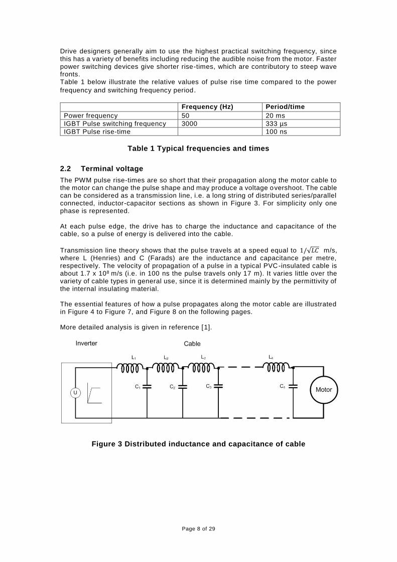
The PWM pulse rise-times are so short that their propagation along the motor cable to the motor can change the pulse shape and may produce a voltage overshoot. The cable can be considered as a transmission line, i.e. a long string of distributed series/parallel connected, inductor-capacitor sections as shown in Figure 3. For simplicity only one phase is represented. At each pulse edge, the drive has to charge the inductance and capacitance of the cable, so a pulse of energy is delivered into the cable.
Transmission line theory shows that the pulse travels at a speed equal to 1/√𝐿𝐶 m/s, where L (Henries) and C (Farads) are the inductance and capacitance per metre, respectively. The velocity of propagation of a pulse in a typical PVC-insulated cable is about 1.7 x 10⁸ m/s (i.e. in 100 ns the pulse travels only 17 m). It varies little over the variety of cable types in general use, since it is determined mainly by the permittivity of the internal insulating material. The essential features of how a pulse propagates along the motor cable are illustrated in Figure 4 to Figure 7, and Figure 8 on the following pages. More detailed analysis is given in reference [1].
Figure 3 Distributed inductance and capacitance of cable
Page 9 of 29
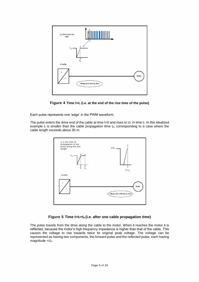
Figure 4 Time t=tr (i.e. at the end of the rise time of the pulse)
Each pulse represents one ‘edge’ in the PWM waveform. The pulse enters the drive end of the cable at time t=0 and rises to Uc in time tr. In this idealized example tr is smaller than the cable propagation time tp, corresponding to a case where the cable length exceeds about 30 m.
Figure 5 Time t=tr+tp (i.e. after one cable propagation time) The pulse travels from the drive along the cable to the motor. When it reaches the motor it is reflected, because the motor’s high frequency impedance is higher than that of the cable. This causes the voltage to rise towards twice its original peak voltage. The voltage can be represented as having two components, the forward pulse and the reflected pulse, each having magnitude +Uc.
tp is the time of propagation of the pulse along the line length
Page 10 of 29
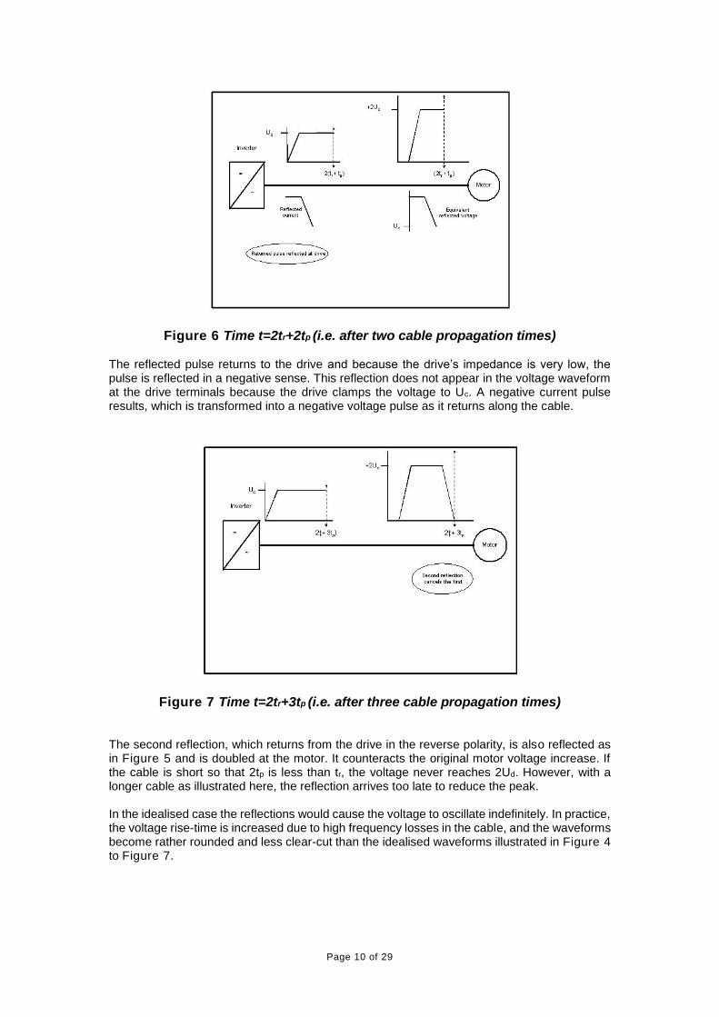
Figure 6 Time t=2tr+2tp (i.e. after two cable propagation times) The reflected pulse returns to the drive and because the drive’s impedance is very low, the pulse is reflected in a negative sense. This reflection does not appear in the voltage waveform at the drive terminals because the drive clamps the voltage to Uc. A negative current pulse results, which is transformed into a negative voltage pulse as it returns along the cable.
Figure 7 Time t=2tr+3tp (i.e. after three cable propagation times) The second reflection, which returns from the drive in the reverse polarity, is also reflected as in Figure 5 and is doubled at the motor. It counteracts the original motor voltage increase. If the cable is short so that 2tp is less than tr, the voltage never reaches 2Ud. However, with a longer cable as illustrated here, the reflection arrives too late to reduce the peak. In the idealised case the reflections would cause the voltage to oscillate indefinitely. In practice, the voltage rise-time is increased due to high frequency losses in the cable, and the waveforms become rather rounded and less clear-cut than the idealised waveforms illustrated in Figure 4 to Figure 7.
Page 11 of 29
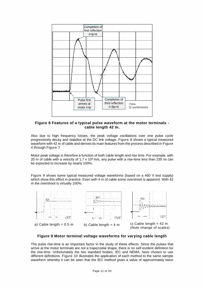
Pulse first arrives at motor t=tp
Completion of first reflection
t=tp+tr
Completion of third reflection
t=3tp+tr
Figure 8 Features of a typical pulse waveform at the motor terminals - cable length 42 m.
Also due to high frequency losses, the peak voltage oscillations over one pulse cycle progressively decay and stabilise at the DC link voltage. Figure 8 shows a typical measured waveform with 42 m of cable and derives its main features from the process described in Figure 4 through Figure 7 Motor peak voltage is therefore a function of both cable length and rise time. For example, with 20 m of cable with a velocity of 1.7 x 10⁸ m/s, any pulse with a rise-time less than 235 ns can be expected to increase by nearly 100%.
Figure 9 shows some typical measured voltage waveforms (based on a 460 V test supply) which show this effect in practice. Even with 4 m of cable some overshoot is apparent. With 42 m the overshoot is virtually 100%.
a) Cable length = 0.5 m
b) Cable length = 4 m
c) Cable length = 42 m (Note change of scales)
Figure 9 Motor terminal voltage waveforms for varying cable length
The pulse rise-time is an important factor in the study of these effects. Since the pulses that arrive at the motor terminals are not a trapezoidal shape, there is no self-evident definition for the rise-time. Unfortunately the two standard bodies, IEC and NEMA, have chosen to use different definitions. Figure 10 illustrates the application of each method to the same sample waveform whereby it can be seen that the IEC method gives a value of approximately twice
Time (2 µs/division)

Page 12 of 29
that calculated using the NEMA definition. All values in this report are given in accordance with the IEC method defined in IEC 60034-17 and IEC 60034-25.
Figure 10 Different definitions of rise time
2.3 Winding Voltage
The voltage overshoot has little effect on the main motor insulation systems between phases and from phase to earth, which are designed to withstand large over voltages. However, because of its short rise-time the voltage overshoot also stresses the insulation between turns, and especially between randomly touching conductors within a coil or between coil ends. The front edge of the voltage pulse with its succession of voltage peaks (Figure 8) will travel around the motor winding as it does along the motor cable, with a measurable propagation time. Figure 11 illustrates how this may result in a large proportion of the pulse appearing between turns, at random points within a coil or between coil ends. This effect progressively decays to a uniform voltage distribution in subsequent coils due to high frequency inductive and capacitive losses.
Figure 11 Propagation of a voltage pulse through motor windings Dependent on motor and winding parameters (e.g. motor rating, type of winding, number of turns, size of coil, turn propagation time etc) and the time between reflected peaks in the
Page 13 of 29
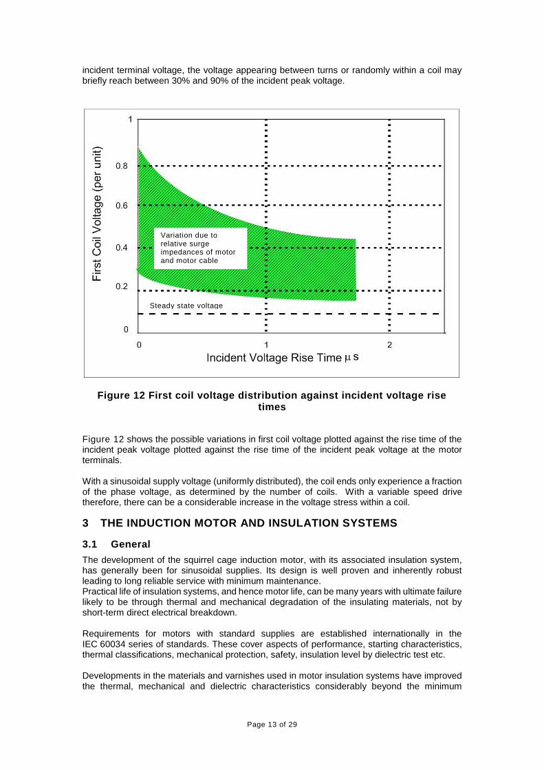
incident terminal voltage, the voltage appearing between turns or randomly within a coil may briefly reach between 30% and 90% of the incident peak voltage.
Figure 12 First coil voltage distribution against incident voltage rise times
Figure 12 shows the possible variations in first coil voltage plotted against the rise time of the incident peak voltage plotted against the rise time of the incident peak voltage at the motor terminals. With a sinusoidal supply voltage (uniformly distributed), the coil ends only experience a fraction of the phase voltage, as determined by the number of coils. With a variable speed drive therefore, there can be a considerable increase in the voltage stress within a coil.
3 THE INDUCTION MOTOR AND INSULATION SYSTEMS
3.1 General
The development of the squirrel cage induction motor, with its associated insulation system, has generally been for sinusoidal supplies. Its design is well proven and inherently robust leading to long reliable service with minimum maintenance. Practical life of insulation systems, and hence motor life, can be many years with ultimate failure likely to be through thermal and mechanical degradation of the insulating materials, not by short-term direct electrical breakdown. Requirements for motors with standard supplies are established internationally in the IEC 60034 series of standards. These cover aspects of performance, starting characteristics, thermal classifications, mechanical protection, safety, insulation level by dielectric test etc. Developments in the materials and varnishes used in motor insulation systems have improved the thermal, mechanical and dielectric characteristics considerably beyond the minimum
Steady state voltage
Variation due to relative surge impedances of motor and motor cable

Page 14 of 29
requirements of those standards and overall, the standard induction motor is well able to withstand the voltage waveforms encountered with the majority of inverter drives.
3.2 Standard Motor Insulation Systems
Motor insulation is generally only defined as the thermal capability, e.g. Class B, Class F or Class H, this does not define the electrical withstand capabilities of the materials used. For low voltage motors up to 690 V, there are two main types of winding, broadly classed as random and form. Lower power motors are generally random wound, i.e. with coils in which the turns of round section wire are randomly located in the coil forming process as illustrated in Figure 13. For larger powers, form windings are often utilised where the pre-formed coils are layered up uniformly - usually with rectangular section conductors.
Figure 13 Random coil forming Coils for both types of windings are shown in Figure 14, with typical slot cross-sections for random and form windings depicted in Figure 15.
Page 15 of 29
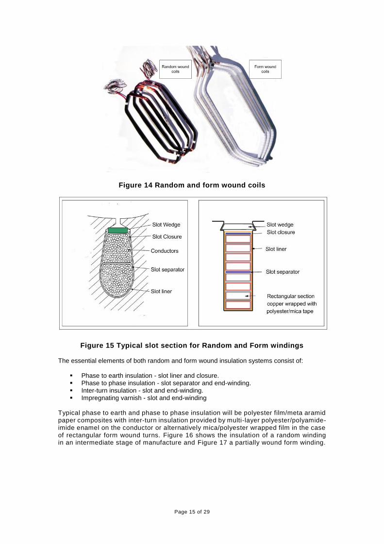
Figure 14 Random and form wound coils
Figure 15 Typical slot section for Random and Form windings The essential elements of both random and form wound insulation systems consist of:
Phase to earth insulation - slot liner and closure. Phase to phase insulation - slot separator and end-winding. Inter-turn insulation - slot and end-winding. Impregnating varnish - slot and end-winding
Typical phase to earth and phase to phase insulation will be polyester film/meta aramid paper composites with inter-turn insulation provided by multi-layer polyester/polyamide-imide enamel on the conductor or alternatively mica/polyester wrapped film in the case of rectangular form wound turns. Figure 16 shows the insulation of a random winding in an intermediate stage of manufacture and Figure 17 a partially wound form winding.

Page 16 of 29
Figure 16 Partially wound stator core with random winding
Figure 17 Partially wound stator core with form winding
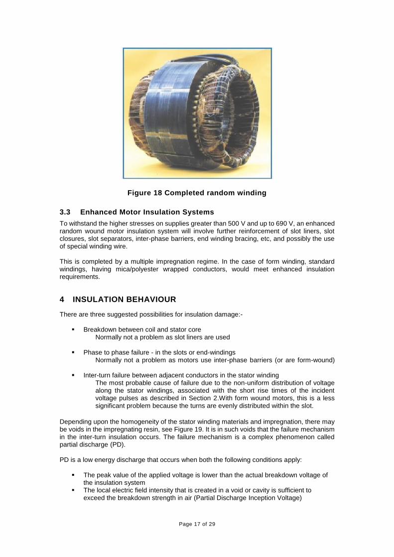
Impregnating the winding, typically with thermal class F or H polyester resin, provides mechanical strength with overall electrical insulation and resistance to environmental contamination. Figure 18 shows a completed random wiring.
Page 17 of 29
Figure 18 Completed random winding
3.3 Enhanced Motor Insulation Systems
To withstand the higher stresses on supplies greater than 500 V and up to 690 V, an enhanced random wound motor insulation system will involve further reinforcement of slot liners, slot closures, slot separators, inter-phase barriers, end winding bracing, etc, and possibly the use of special winding wire. This is completed by a multiple impregnation regime. In the case of form winding, standard windings, having mica/polyester wrapped conductors, would meet enhanced insulation requirements.
4 INSULATION BEHAVIOUR
There are three suggested possibilities for insulation damage:-
Breakdown between coil and stator core Normally not a problem as slot liners are used
Phase to phase failure - in the slots or end-windings Normally not a problem as motors use inter-phase barriers (or are form-wound)
Inter-turn failure between adjacent conductors in the stator winding The most probable cause of failure due to the non-uniform distribution of voltage along the stator windings, associated with the short rise times of the incident voltage pulses as described in Section 2.With form wound motors, this is a less significant problem because the turns are evenly distributed within the slot.
Depending upon the homogeneity of the stator winding materials and impregnation, there may be voids in the impregnating resin, see Figure 19. It is in such voids that the failure mechanism in the inter-turn insulation occurs. The failure mechanism is a complex phenomenon called partial discharge (PD). PD is a low energy discharge that occurs when both the following conditions apply:
The peak value of the applied voltage is lower than the actual breakdown voltage of the insulation system
The local electric field intensity that is created in a void or cavity is sufficient to exceed the breakdown strength in air (Partial Discharge Inception Voltage)

Page 18 of 29
When subject to continuous partial discharges, the insulation system progressively degrades, prematurely ageing the insulation material. The ageing process results from an erosion of the insulation material, reducing its thickness at the discharge sites until its breakdown voltage capability is reduced to below the level of the applied voltage peak, at this stage insulation breakdown occurs. Investigations, particularly at Dresden University [3] have produced relationships for model insulation systems between the applied peak voltage, rise times, the probability of PD and the insulation lifetime. The results are shown in Figure 20 for a reference temperature of 20°C with a typical standard induction motor insulation system that is rated for operation with a nominal supply voltage up to 500V a.c. on an inverter supply. Figure 20 (a) which is based on the Dresden results, shows the cumulative number of pulses (0.1 µs rise time, 5 µs duration) that the insulation should survive whilst Figure 20 (b) shows the probability of PD occurring, both plotted against the pulse amplitude of the applied voltage. PD inception voltage is influenced by temperature.
Conductor
Conductor insulation
Slot liner insulation
Core
assembly
Figure 19 Voids in insulation

Page 19 of 29
Figure 20 Relationship between Peak voltage, Insulation life time, and PD probability
Temperature increases occur from the normal losses in the motor, compounded to some extent by the losses associated with the high frequency nature of the applied voltage pulse. Reports [3] indicate that an increase in temperature of 80 K may reduce the PD inception voltage by approximately 10%. In circumstances where partial discharges are occurring this reduction in the inception voltage will result in an acceleration of the ageing of the insulation system. If the motor insulation system is operated such that the applied peak voltage is less than the PD inception voltage, or at a voltage where the probability of PD is low and the number of pulses to breakdown exceeds 1012 in Figure 20, then no reduction in lifetime is expected. In relating the unipolar curve of Figure 16 to standard insulation windings, it is necessary to apply correction factors for temperature and the first coil voltage (Figure 20). For the normal class B temperature rise (80 K), these factors effectively equalise each other indicating a permissible terminal voltage peak of 1.3 kV with a rise time of 0.1 µs for a projected lifetime of 1013 pulses. This equates to the practical situation of standard motors from BEAMA manufacturers and supply voltages up to and including 500 V a.c. (see curve A in Figure 21).
4.1 Bipolar Switching Methods
Bipolar switching, where the polarity of the inverter output pulses may be reversed in successive switching operations (thereby producing alternating pulses), may be found in inverters which use hysteresis switching unless inhibited in the implementing technology. In these cases, a conventional PWM modulator is not used, and the output may offer different switching patterns. In these control schemes it is possible to generate pulses which change from +Ud to -Ud in one transition unless inhibited in the design implementation. Note that it is theoretically possible to obtain peak voltage reflections, as described in Figure 4 to Figure 7, of up to 4Ud. (See also section 7.6) If frequent polarity reversals occur the stress on insulation is increased and thus the predicted failure time is decreased as can be seen in Figure 20.

Page 20 of 29
5 PRACTICAL INSULATION REQUIREMENTS
Augmented insulation systems have existed for many years to protect motor insulation from switching transients, however, IEC (60034-17 and 60034-25) and NEMA (MG1 part 31:2014) have both reviewed their respective standards giving withstand characteristics for motor insulation systems when inverter fed. In both cases, these curves are now more representative of present day practice - see Figure 21 below.
Figure 21 limit curves of admissible motor terminal peak voltage for a.c. motors up to and including 500 V a.c. (Curve A) and from >500 V a.c. to
690 V a.c. (Curve B)
Notes: i) Motor pulse withstand requirements on 400/415V supply generally exceed the
minimum capability specified in IEC 60034-17. ii) The pulse withstand requirements detailed in NEMA Application Guide for AC
Adjustable Speed Drive Systems, 2002 for definite purpose inverter fed motors (Vpeak = 3.1 * Vrated for NEMA rise times ≥ 0.1 µs and Vrated ≤ 600 V a.c. ) are not adequate for all cases of modern PWM inverter operation.
iii) Pulse rise times shown are normalised in accordance with the IEC 60034-17 definition.
The example measurements shown are typical of lower power motor and are for illustrative purposes only as the actual peak voltages are dependent on a series of factors including - motor rating, winding configuration, connection details (star or delta) and cable type/size. However, the test results plotted in Figure 21 illustrate in principle the effect of lengthening the motor cable. The rise time increases steadily with increasing length, whilst the peak voltage overshoot tends to reduce after a maximum at about 50 m. The voltage stress on the motor therefore usually declines above quite moderate cable lengths (except in the special case of very long motor cables described in Section 7.7).
From the test results given in Figure 21 above, it can be seen that standard PWM drives with cable lengths of 20 m or more can produce peak voltages at the motor terminals that are outside
µ

Page 21 of 29
the IEC 60034-17 profile, even when operating from a 400/415 V a.c. supply. Curve A (which corresponds to IEC 60034-25) indicates that BEAMA motor manufacturers produce, as standard, motors whose capability substantially exceeds the requirements of IEC 60034-17, and the enhanced insulation systems developed by BEAMA manufacturers exceeds the NEMA curve requirements and comfortably meet the 690 V peak voltage requirements. Figure 21 can be used in discussions with non BEAMA motor manufacturers to indicate the peak voltage/rise-time withstand profile that is required for reliable operation (Curve A or B depending on supply voltage) and to ensure that the expected operating life is achieved. An alternative motor supplier should be asked to confirm this capability.
6 ALTERNATIVE PREVENTATIVE METHODS
6.1 General
In applications where it is not feasible to employ motors which meet the withstand capability achieved with standard or enhanced insulation given in Figure 21 curve A or B respectively, some form of alternative solution is required. Examples where these alternative solutions may be required include:
Undefined motor characteristics Retrofit application of VSDs to ‘old’ motors Motors with inadequate pulse withstand capabilities
In the above cases, some form of motor terminal voltage modification technique is necessary. These techniques essentially involve placing additional apparatus between the motor and the inverter to limit the rate of rise of the pulse, reduce the reflection coefficient and thereby reduce the peak voltage level. Some of the devices are also used to compensate for large capacitive cable charging currents. These techniques may be summarised as follows:
Output Reactors Output dv/dt Filters (sometimes known as dU/dt filters) Sinusoidal Filters Motor Termination Units
These solutions should be correctly matched to the application and the basic characteristics are as described below. In each case the effects of volt drop in the device on the final terminal voltage should be established.
6.2 Output Reactors
These are specially designed reactors, which can accommodate the PWM causing undue reactor heating and can also provide the necessary inductance
frequency spectrum needed. They are used to reduce the dv/dt and peak care is needed as reactors can theoretically extend the duration of overshoot if
selected - particular care is needed with ferrite core reactors. In the case shown in Figure 22, which compares to
Figure 9 (42 m case), the addition of the reactor has extended the rise time to around 5 µs and reduced the peak voltage to 792 V - acceptable to most standard motors. Normally, the output reactor is mounted within the inverter cabinet and of course leads to the acceptance of extra space, cost and reduced efficiency (less than approx. 0.5%). Output reactors can also be used to compensate for cable charging currents (balances cable capacitance) and may be used for motor cable lengths up to many hundred metres on larger drives (check technical data).

Page 22 of 29
Figure 22 Output inductor
6.3 Voltage Limiting Filter (dv/dt Filter)
In this case, a design consisting of capacitors, inductors and diodes or resistors may be used to limit the dv/dt to typically less than 500 V/µs, drastically reducing both the amplitude and the rate of rise of the peak voltage. In the example shown in Figure 23 the peak voltage is reduced to 684 V with a dv/dt of 40 V/µs. Such filters allow the use of most motors without problem and are therefore recommended if the data of a motor is unknown (e.g. in the case of a retrofit), particularly on higher voltage supplies (›500 V). Increased losses of 0.5 - 1.0% must be accommodated.
Figure 23 Output dv/dt filter
6.4 Sinusoidal Filter
A special design of low pass filter allows the high frequency currents to be shunted away. This resulting waveform at the motor becomes sinusoidal, the voltage and current are, for one cycle of the waveform, as shown in Figure 24. These types of filters are the most expensive and

Page 23 of 29
also have other limitations. They prevent the motor voltage from exceeding 90% of the supply voltage (thereby de-rating the inverter).They also will not be suitable for applications that require high dynamic performance. However, they have the following additional advantages:
Reduced motor noise Reduced motor losses Simplifies hazardous area motor certification Allows use of standard motors and long motor cables (eliminates capacitive charging
currents) Reduced radiated high frequency emissions (EMC)
Figure 24 Sinusoidal output filter
6.5 Motor Termination Unit
Some manufacturers produce series-resistive/capacitive filters, which may be locally connected at the motor terminals (usually as an extra box mounted near to the motor).
Figure 25 Motor termination unit
The fast rising incident pulse sees the capacitor as a short circuit and the resistive element is temporarily connected across the end of the cable. If this resistor

Page 24 of 29
approximates to the characteristic impedance of the cable, over voltages will not occur. As the capacitor charges, the current through the circuit reduces - therefore the losses in the resistor are limited to the rising edge duration. Typically, these filters add around 0.5 - 1.0% losses.
For example illustrated in Figure 25 the peak voltage is now only 800 V with a rise time of 2 µs which should be suitable for most motors. To date, these devices have not been popular. One concern is that the parallel connection would be compromised thereby subjecting the motor to the high transients without any warning. Some users [4] have reported potential difficulties in matching the inverter current rating to the motor rating to obtain the inherent l2t protection facilities available on many drives (presumably due to the terminator capacitive charging current). Termination units must not be used with motors designed for use in explosive atmospheres (‘Ex’ motors - see Section 7.6).
6.6 Relative Characteristics of Preventative Measures
The relative motor terminal voltage characteristics [5] of the preventative above are shown in Figure 22 to Figure 25 and should be compared with the
earlier Figure 9(c). The mitigation methods below are specific to the motor/inverter installation and the actual selection should therefore be advised by the drive supplier.
6.7 Cost comparison for preventative measures
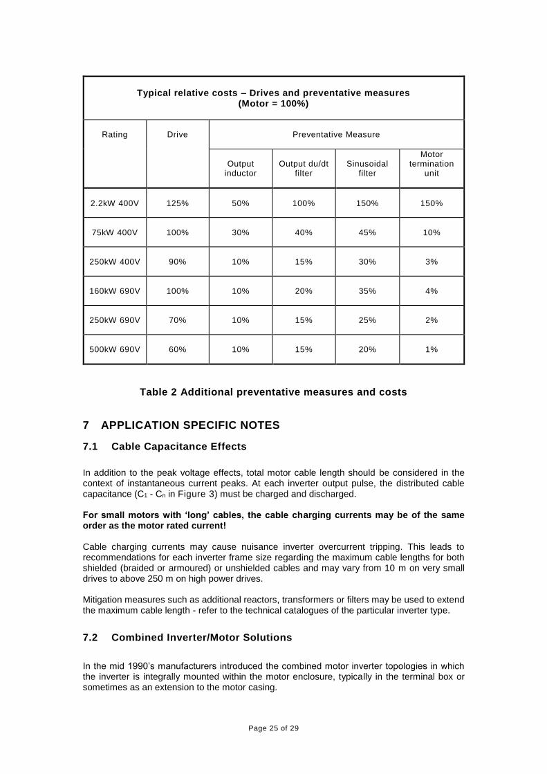
In considering the relative merits of the competing solutions, the issue of costs should also be considered. The table below gives some indications.
Page 25 of 29
Typical relative costs – Drives and preventative measures
(Motor = 100%)
Rating
Drive
Preventative Measure
Output
inductor
Output du/dt
filter
Sinusoidal
filter
Motor termination
unit
2.2kW 400V
125%
50%
100%
150%
150%
75kW 400V
100%
30%
40%
45%
10%
250kW 400V
90%
10%
15%
30%
3%
160kW 690V
100%
10%
20%
35%
4%
250kW 690V
70%
10%
15%
25%
2%
500kW 690V
60%
10%
15%
20%
1%
Table 2 Additional preventative measures and costs
7 APPLICATION SPECIFIC NOTES
7.1 Cable Capacitance Effects
In addition to the peak voltage effects, total motor cable length should be considered in the context of instantaneous current peaks. At each inverter output pulse, the distributed cable capacitance (C1 - Cn in Figure 3) must be charged and discharged. For small motors with ‘long’ cables, the cable charging currents may be of the same order as the motor rated current! Cable charging currents may cause nuisance inverter overcurrent tripping. This leads to recommendations for each inverter frame size regarding the maximum cable lengths for both shielded (braided or armoured) or unshielded cables and may vary from 10 m on very small drives to above 250 m on high power drives. Mitigation measures such as additional reactors, transformers or filters may be used to extend the maximum cable length - refer to the technical catalogues of the particular inverter type.
7.2 Combined Inverter/Motor Solutions
In the mid 1990’s manufacturers introduced the combined motor inverter topologies in which the inverter is integrally mounted within the motor enclosure, typically in the terminal box or sometimes as an extension to the motor casing.

Page 26 of 29
The very short cable length between the inverter output connections and the motor windings limits the reflections and therefore the peak voltage problems do not exist. Taken in the context of the additional benefits of simplified installation, reduced EMC problems and lower overall costs, this solution is well suited to lower power applications and is now rapidly gaining market acceptance.
7.3 Applications With Frequent or Continuous Braking Duties
For applications such as powered unwind stands on web handling machines, the motor may spend a large part of its operating time in the braking mode. The braking energy is transferred through flywheel diodes back on to the intermediate DC link, thereby giving a 15-20% increase in the DC link voltage (and also therefore the peak motor voltage). The effect is similar to increasing the voltage supply by up to 20%; this should be taken into consideration - e.g. treat a 400 V application as if it was supplied with 480 V (therefore a standard motor would still be suitable).
7.4 Active Front End (Sinusoidal Rectifier) Considerations
For drives with PWM active front ends (regenerative and/or unity power factor), special considerations may be required. As a function of the operation of active front end drives, the DC link voltage is continuously between 10-15% higher than for standard inverters. The effect is similar to increasing the supply voltage by up to 15%; this should be taken into consideration - e.g. treat a 480 V application as if it was supplied with 550 V (therefore enhanced insulation or other preventative measure is now required). Refer to the inverter supplier for further guidance.
7.5 Passive Series Harmonic Filter Considerations
Series harmonic filters tend to increase the input terminal voltage to the rectifier, and the manufacturer’s advice should always be sought.
7.6 Drive Switching Strategies
As described in Section 4, some drive types use control strategies which could allow bipolar switching. These systems could theoretically double the motor peak voltage stress. GAMBICA inverter manufacturers implement control mechanisms to inhibit bipolar switching.
7.7 Explosive Atmosphere Approval
The application of inverters to ‘Ex’ motors may invalidate the hazardous area certification – refer to the motor manufacturer. Refer to the appropriate GAMBICA/BEAMA Technical Report.
7.8 Applications with ‘Very Long’ Cable Lengths
The definition of ‘very long’ depends on the drive rating and type, and may vary between 250 m for lower power drives and 500 m for higher power ratings - refer to manufacturers technical documentation. For these applications, new factors, which could influence the voltage stress, are introduced, and the drive supplier should be consulted.
7.9 Special motors
Special motors are used in some circumstances, such as in petrochemical pumps, where the pumped medium is in contact with the windings. In these cases the experience of the motor designer should be requested to give guidance to the permissible levels of voltage stress.

Page 27 of 29
8 CONCLUSIONS
A combination of fast switching semiconductors and ‘long’ motor cables can cause peak voltages up to twice the DC link voltage (2.7 times the supply voltage) due to transmission line effects. In extreme cases, this high peak voltage and the uneven voltage distribution in the motor windings can cause a low energy partial discharge between turns of the first coil. Partial discharge can cause premature ageing effects of the winding insulation system until failure occurs.
By selecting the correct motor, or by the use of appropriate preventative measures,
damaging partial discharge can be avoided, thereby ensuring the maximum motor life is achieved.
Following the recommendations described in this report will ensure that motor insulation life is not compromised.

Page 28 of 29
9 GLOSSARY OF TERMS
Term or abbreviation Description Section
a.c. Alternating current General
ATEX
“Atmosphères Explosibles” – European Directives using French acronym, covering the essential health and safety requirements for products used in potentially explosive atmospheres
7.7, etc.
BSI
British Standards Institution – responsible for the preparation of UK National Standards, prefixed BS *** and publication of harmonised standards in the UK, prefixed BS EN ***
General
CE Marking Indication of compliance with all appropriate EU Directives
General
CEMEP European Committee of Manufacturers of Electrical Machines and Power Electronics
General
CEN European Committee for Standardisation, responsible for the preparation of non electro-technical harmonised (EN) standards
General
CENELEC
European Committee for the Electrotechnical Standardisation – responsible for the preparation of electro-technical harmonised (EN) standards
General
d.c. Direct Current General
du/dt or dv/dt Rate of change of voltage General
EN Standard issued by CEN/CENELEC, normally prefixed by the national issuing body e.g. BS EN
General
IEC International Electrotechnical Commission – International Standardisation Body. Also the prefix for standards prepared by this organisation
General
IGBT Insulated gate bipolar transistor General
NEMA National Electrical Manufacturers Association (USA) General
PD Partial discharge General
PWM Pulse Width Modulated General
U or V Voltage (Generally used with suffixes) General

Page 29 of 29
10 REFERENCES
1. Persson E, “Transient Effects in Application of PWM inverters to Induction Motors” - IEEE-IAS 28.1095-1101, 1992
2. Mohan, Undeland & Robbins, “Power Electronic Converters, Application & Design” -
Wiley 1989
3. Kaufhold M, Borner G, Eberhardt M, Speck J, “Failure Mechanisms of the Interturn Insulation of Low Voltage Machines Fed by Pulse Controlled Inverters” - IEEE Electrical Insulation Magazine Vol 12, No. 5, 1996
4. Doherty, K G, “Investigation of Voltage Reflections Associated with PWM Inverter
Installations” - IEE Submission 1996
5. Finlayson P T, “Output Filter Considerations for PWM Inverter Drives With Induction Motors” - IEEE, Industry Application Magazine Jan 1998
11 FURTHER READING
a] GAMBICA/BEAMA, Technical Report No 2 “Motor shaft voltages and bearing currents under PWM inverter operation”
b] GAMBICA/BEAMA, Technical Report No 3 “Installation Guide for Power Drive
Systems”
c] GAMBICA/BEAMA, Technical Report No 4 “Application of the ATEX Directives to Power Drive Systems”
d] IEC 60034-17: “Rotating electrical machines - Cage induction motors when fed from converters - Application guide”
e] IEC 60034-25: “Guidance for the design and performance of a.c. motors specifically designed for converter supply”
f] IEC 60034-18-41 “Qualification and type tests for Type I electrical insulation systems used in rotating electrical machines fed from voltage converters”
g] IEC 60034-27 ”Off-line partial discharge measurements on the stator winding insulation of rotating electrical machines”
h] IEC TS 60034-27-2 “On-line partial discharge measurements on the stator winding insulation of rotating electrical machines”
i] IEC 62068 “Electrical insulating materials –General method of evaluation of electrical
endurance under repetitive voltage impulses”
j] NEMA Application Guide for AC Adjustable Speed Drive Systems
k] NEMA MG1-2014: Motors and Generators - part 30 - “Application considerations for constant speed motors used on a sinusoidal bus with harmonic content and general purpose motors used with adjustable-voltage or adjustable-frequency controls or both”
l] NEMA MG1-2014: Motors and Generators-part 31 “Definite purpose inverter fed polyphase motors”