
Summaries from, Thermodynamics: An Engineering · PDF fileSummaries from, Thermodynamics: An...
21
i AE1104 Physics 1 Summaries from, Thermodynamics: An Engineering Approach (Sixth Edition) Made by: E. Bruins Slot
Transcript of Summaries from, Thermodynamics: An Engineering · PDF fileSummaries from, Thermodynamics: An...
i
AE1104 Physics 1
Summaries from,Thermodynamics: An Engineering Approach (Sixth Edition)
Made by:E. Bruins Slot

Chapter 1
Introduction and Basic Concepts
In this chapter, the basic concepts of thermodynamics are introduced and discussed. Thermodynamicsis the science that primarily deals with energy. The first law of thermodynamics is simply anexpression of the conservation of energy principle, and it asserts that energy is a thermodynamicproperty. The second law of thermodynamics asserts that energy has quality as well as quantity, andactual processes occur in the direction of decreasing quality of energy.A system of fixed mass is called a closed system, or control mass, and a system that involves masstransfer across its boundaries is called an open system, or control volume. The mass-dependentproperties of a system are called extensive properties and the others intensive properties. Density ismass per unit volume, and specific volume is volume per unit mass.A system is said to be in thermodynamic equilibrium if it maintains thermal, mechanical, phaseand chemical equilibrium. Any change from one state to another is called a process. A processwith identical end states is called a cycle. During a quasi-static or quasi-equilibrium process, thesystem remains practically in equilibrium at all times. The state of a simple, compressible system iscompletely specified by two independent, intensive properties.The zeroth law of thermodynamics states that two bodies are in thermal equilibrium if both have thesame temperature reading even if they are not in contact.The temperature scales used in the SI and English system today are the Celsius scale and theFahrenheit scale, respectively. They are related to absolute temperature scales by
T (K) = T (◦C)+273.15
T (R) = T (◦F)+459.67
The magnitudes of each division of 1 K and 1 ◦C are identical, and so are the magnitudes of eachdivision of 1 R and 1 ◦F . Therefore,
∆T (K) = ∆T (◦C) and ∆T (R) = ∆T (◦F)
The normal force exerted by a fluid per unit area is called pressure, and its unit is the pascal ,1 Pa = 1 N/m2. The pressure relative to absolute vacuum is called the absolute pressure, and thedifference between the absolute pressure and the local atmospheric pressure is called the gagepressure. Pressures below atmospheric pressure are called vacuum pressures. The absolute, gage,and vacuum pressures are related by
Pgage = Pabs−Patm (for pressures above Patm)
Pvac = Patm−Pabs (for pressures below Patm)
1

The pressure at a point in a fluid has the same magnitude in all directions. the variation of pressurewith elevation is given by
dPdz
=−ρg
where the positive z direction is taken to be upward. When the density of the fluid is constant, thepressure difference across a fluid layer of thickness ∆z is
∆P = P2−P1 = ρg∆z
The absolute and gage pressures in a liquid open to the atmosphere at a depth h from the free surfaceare
P = Patm +ρgh or Pgage = ρgh
Small to moderate pressure differences are measured by a manometer. The pressure in a stationaryfluid remains constant in the horizontal direction. Pascal’s principle states that the pressure appliedto a confined fluid increases the pressure thoughout by the same amount. the atmospheric pressure ismeasured by a barometer and is given by
Patm = ρgh
where h is the height of the liquid column.
Chapter 2
Energy, Energy Transfer, and General EnergyAnalysis
The sum of all forms of energy of a system is called total energy, which consists of internal, kinetic,and potential energy for simple compressible systems. Internal energy represents the molecularenergy of a system and may exist in sensible, latent, chemical, and nuclear forms.Mass flow rate m is defined as the amount of mass flowing through a cross section per unit time. It isrelated to the Volume flow rate V , which is the volume of a fluid flowing through a cross section perunit time, by
m = ρV = ρAcVavg
(kgs
)The energy flow rate associated with a fluid flowing at a rate of m is
E = me(
kJs
or kW)
which is analogous to E = me.The mechanical energy is defined as the form of energy that can be converted to mechanical workcompletely and directly by a mechanical device such as an ideal turbine. It is expressed on a unitmass basis and rate form as
emech =Pρ+ V 2
2 +gz
and
Emech = memech = m(
Pρ+ V 2
2 +gz)
where P/ρ is the flow energy, V 2/2 is the kinetic energy, and gz is the potential energy of the fluidper unit mass.Energy can cross the boundaries of a closed system in the form of heat or work. For control volumes,energy can also be transported by mass. If the energy transfer is due to a temperature differencebetween a closed system and its surroundings, it is heat; otherwise, it is work.Work is the energy transfered as a force acts on a system through a distance. Various forms of workare expressed as follows:
Electrical work: We =VVV I∆t
Shaft work: Wsh = 2πnT
Spring work: Wspring =12 k(x2
2− x21)
3
The first law of thermodynamics is essentially an expression of the conservation of energy principle,also called the energy balance. The general mass and energy balances for any system undergoingany process can be expressed as
Ein−Eout︸ ︷︷ ︸Net energy transfer by heat,work, and mass
= ∆Esystem︸ ︷︷ ︸Changes in internal, kinetic, potential, etc., energies
(kJ)
It can also be expressed in the rate form as
Ein− Eout︸ ︷︷ ︸Rate of net energy transfer by heat,work, and mass
=∆Esystem
dt︸ ︷︷ ︸Rate of changes in internal, kinetic, potential, etc., energies
(kW )
The efficiencies of various devices are defined as
ηpump =∆Emech, f luid
Wsha f t,in=
Wpump,u
Wpump
ηturbine =Wsha f t,out
|∆Emech, f luid |= Wturbine
Wturbine,e
ηmotor =Mechanical power output
Electrical power input =Wsha f t,out
Welect,in
ηgenerator =Electrical power outputMechanical power input =
Welect,out
Wsha f t,in
ηpump−motor = ηpumpηmotor =Wpump,u
Welect,in=
∆Emech, f luid
Welect,in
ηturbine−generator = ηturbineηgenerator =Welect,out
Wturb,in=
Welect,out
|∆Emech, f luid |
The conversion of energy from one form to another is often associated with adverse effects on theenvironment, and environmental impact should be an important consideration in the conversion andutilization of energy.
Chapter 3
Properties of Pure Substances
A substance that has a fixed chemical composition throughout is called a pure substance. A puresubstance exists in different phases depending on its energy level. In the liquid phase, a substancethat is not about to vaporize is called a compressed or subcooled liquid. In the gas phase, a substancethat is not about to condense is called a superheated vapor. During a phase-change process, thetemperature and pressure of a pure substance are dependent properties. At a given pressure, asubstance changes phase at a fixed temperature, called the saturation temperature. Likewise, at agiven temperature, the pressure at which a substance changes phase is called the saturation pressure.During a boiling process, both the liquid and the vapor phases coexist in equilibrium, and under thiscondition the liquid is called saturated liquid and the vapor saturated vapor.In a saturated liquid-vapor mixture, the mass fraction of vapor is called the quality and is expressedas
x =mvapor
mtotal
Quality may have values between 0 (saturated liquid) and 1 (saturated vapor). It has no meaning inthe compressed liquid or superheated vapor regions. In the saturated mixture region, the averagevalue of any intensive property y is determined from
y = y f + xy f g
where f stands for saturated liquid and g for saturated vapor.In the absence of compressed liquid data, a general approximation is to treat a compressed liquid asa saturated liquid at the given temperature,
y∼= y f @T
Where y is v, u or h.The state beyond which there is no distinct vaporization process is called the critical point. Atsupercritical pressures, a substance gradually and uniformly expands from the liquid to vapor phase.All three phases of a substance coexist in equilibrium at states along the triple line characterized bytriple-line temperatures and pressures. The compressed liquid has lower v, u, and h values than thesaturated liquid at the same T or P. Likewise, superheated vapor has higher v, u, and h values thanthe saturated vapor at the same T or P.Any relation among the pressure, temperature, and specific volume of a substance is called anequation of state. The simplest and best-known equation of state is the ideal-gas equation of state,given as
Pv = RT
5
where R is the gas constant. Caution should be exercised in using this relation since an ideal gasis a fictitious substance. Real gases exhibit ideal-gas behavior at relatively low pressures and hightemperatures.The deviation from ideal-gas behavior can be properly accounted for by using the compressibilityfactor Z, defined as
Z = PvRT
or
Pv = ZRT
the Z factor is approximately the same for all gases at the same reduced temperature and reducedpressure, which are defined as
PR =P
Pcrand TR =
TTcr
where Pcr and Tcr are the critical pressure and temperature, respectively. This is known as theprinciple of corresponding states. When either P or T is unknown, it can be determined from thecompressibility chart with the help of the pseudo-reduced specific volume, defined as
vR =vactual
RTcr/Pcr
The P−v−T behavior of substances can be represented more accurately by more complex equationsof state. Three of the best known areVan der Waals: (
P+ av2
)(v−b) = RT
where
a = 27R2T 2cr
64Pcrand b = RTcr
8Pcr
Beattie-Bridgeman:
P = RuTv2
(1− c
vT 3
)(v+B)− A
v2
where
A = A0(1− a
v
)and B = B0
(1− b
v
)Benedict-Webb-Rubin:
P =RuT
v+
(B0RuT −A0−
C0
T 2
)1v2 +
bRuT −av3 +
aα
v6 +c
v3T 2
(1+
γ
v2
)e−
γ
v2
where Ru is the universal gas constant and v is the molar specific volume.
Chapter 4
Energy Analysis of Closed Systems
Work is the energy transferred as a force acts on a system through a distance. The most commonform of mechanical work is the boundary work, which is the work associated with the expansionand compression of substances. On a P−V diagram, the area under the process curve represents theboundary work for a quasi-equilibrium process. Various forms of boundary work are expressed asfollows:
General
Wb =2∫1
PdV (kJ)
Isobaric process
Wb = P0(V2−V1) (P1 = P2 = P0 = constant)
Polytropic process
Wb =P2V2−P1V1
1−n (n 6= 1) (PV n = constant)
Isothermal process of an ideal gas
Wb = P1V1 ln V2V1
= mRT0 ln V2V1
(PV = mRT0 = constant)
The first law of thermodynamics is essentially an expression of the conservation of energy princi-ple, also called the energy balance. The general energy balances for any system undergoing anyprocess can be expressed as
Ein−Eout︸ ︷︷ ︸Net energy transfer by heat,work, and mass
= ∆Esystem︸ ︷︷ ︸Changes in internal, kinetic, potential, etc., energies
(kJ)
It can also be expressed in the rate form as
Ein− Eout︸ ︷︷ ︸Rate of net energy transfer by heat,work, and mass
=∆Esystem
dt︸ ︷︷ ︸Rate of changes in internal, kinetic, potential, etc., energies
(kW )
7
Taking heat transfer to the system and work done by the system to be positive quantities, the energybalance for a closed system can also be expressed as
Q−W = ∆U +∆KE +∆PE (kJ)
Where
W =Wother +Wb
∆U = m(u2−u1)
∆KE = 12 m(V 2
2 −V 21 )
∆PE = mg(z2− z1)
For a constant-pressure process, Wb +∆U = ∆H. Thus,
Q−Wother = ∆H +∆KE +∆PE (kJ)
The amount of energy needed to raise the temperature of a unit mass of a substance by one degree iscalled the specific heat at constant volume cv for a constant-volume process and the specific heat atconstant pressure cP for a constant-pressure process. They are defined as
cv =
(δuδT
)v
and cP =
(δhδT
)P
For ideal gases u, h, cv, and cP are functions of temperature alone. The ∆u and ∆h of ideal gases areexpressed as
∆u = u2−u1 =2∫1
cv(T )dT ∼= cv,avg(T2−T1)
and
∆h = h2−h1 =2∫1
cP(T )dT ∼= cP,avg(T2−T1)
For ideal gases, cv and cP are related by
cP = cv +R(
kJkg ·K
)where R is the gas constant. The specific heat ratio k is defined as
k =cP
cv
For incompressible substances (liquids and solids), both the constant-pressure and constant-volumespecific heats are identical and denoted by c:
cP = cv = c(
kJkg ·K
)
The ∆u and ∆h of incompressible substances are given by
∆u = u2−u1 =2∫1
c(T )dT ∼= cavg(T2−T1)(
kJkg
)∆h = ∆u+ v∆P
(kJkg
)
Chapter 5
Mass and Energy Analysis of Control Volumes
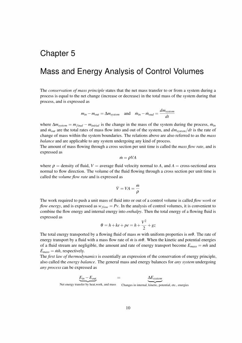
The conservation of mass principle states that the net mass transfer to or from a system during aprocess is equal to the net change (increase or decrease) in the total mass of the system during thatprocess, and is expressed as
min−mout = ∆msystem and min− moud =dmsystem
dt
where ∆msystem = m f inal −minitial is the change in the mass of the system during the process, min
and mout are the total rates of mass flow into and out of the system, and dmsystem/dt is the rate ofchange of mass within the system boundaries. The relations above are also referred to as the massbalance and are applicable to any system undergoing any kind of process.The amount of mass flowing through a cross section per unit time is called the mass flow rate, and isexpressed as
m = ρVA
where ρ = density of fluid, V = average fluid velocity normal to A, and A = cross-sectional areanormal to flow direction. The volume of the fluid flowing through a cross section per unit time iscalled the volume flow rate and is expressed as
V =VA =mρ
The work required to push a unit mass of fluid into or out of a control volume is called flow work orflow energy, and is expressed as w f low = Pv. In the analysis of control volumes, it is convenient tocombine the flow energy and internal energy into enthalpy. Then the total energy of a flowing fluid isexpressed as
θ = h+ ke+ pe = h+V 2
2+gz
The total energy transported by a flowing fluid of mass m with uniform properties is mθ . The rate ofenergy transport by a fluid with a mass flow rate of m is mθ . When the kinetic and potential energiesof a fluid stream are negligible, the amount and rate of energy transport become Emass = mh andEmass = mh, respectively.The first law of thermodynamics is essentially an expression of the conservation of energy principle,also called the energy balance. The general mass and energy balances for any system undergoingany process can be expressed as
Ein−Eout︸ ︷︷ ︸Net energy transfer by heat,work, and mass
= ∆Esystem︸ ︷︷ ︸Changes in internal, kinetic, potential, etc., energies
10
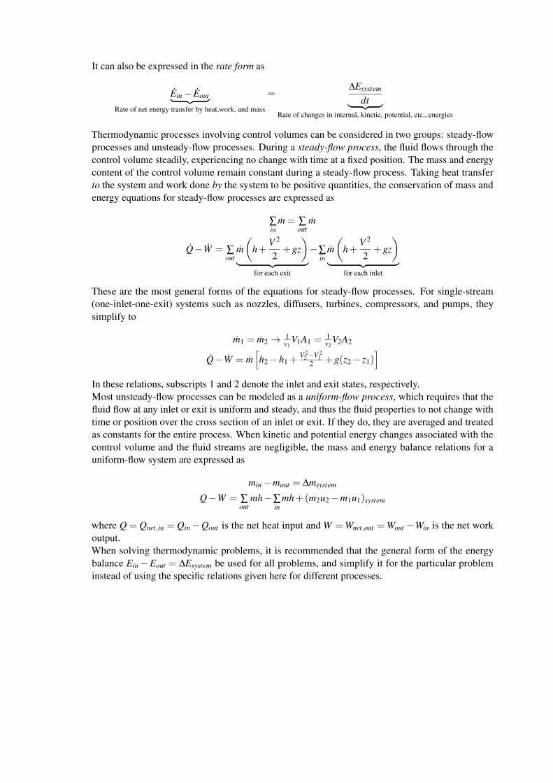
It can also be expressed in the rate form as
Ein− Eout︸ ︷︷ ︸Rate of net energy transfer by heat,work, and mass
=∆Esystem
dt︸ ︷︷ ︸Rate of changes in internal, kinetic, potential, etc., energies
Thermodynamic processes involving control volumes can be considered in two groups: steady-flowprocesses and unsteady-flow processes. During a steady-flow process, the fluid flows through thecontrol volume steadily, experiencing no change with time at a fixed position. The mass and energycontent of the control volume remain constant during a steady-flow process. Taking heat transferto the system and work done by the system to be positive quantities, the conservation of mass andenergy equations for steady-flow processes are expressed as
∑in
m = ∑out
m
Q−W = ∑out
m(
h+V 2
2+gz
)︸ ︷︷ ︸
for each exit
−∑in
m(
h+V 2
2+gz
)︸ ︷︷ ︸
for each inlet
These are the most general forms of the equations for steady-flow processes. For single-stream(one-inlet-one-exit) systems such as nozzles, diffusers, turbines, compressors, and pumps, theysimplify to
m1 = m2→ 1v1
V1A1 =1v2
V2A2
Q−W = m[h2−h1 +
V 22 −V 2
12 +g(z2− z1)
]In these relations, subscripts 1 and 2 denote the inlet and exit states, respectively.Most unsteady-flow processes can be modeled as a uniform-flow process, which requires that thefluid flow at any inlet or exit is uniform and steady, and thus the fluid properties to not change withtime or position over the cross section of an inlet or exit. If they do, they are averaged and treatedas constants for the entire process. When kinetic and potential energy changes associated with thecontrol volume and the fluid streams are negligible, the mass and energy balance relations for auniform-flow system are expressed as
min−mout = ∆msystem
Q−W = ∑out
mh−∑in
mh+(m2u2−m1u1)system
where Q = Qnet,in = Qin−Qout is the net heat input and W =Wnet,out =Wout −Win is the net workoutput.When solving thermodynamic problems, it is recommended that the general form of the energybalance Ein−Eout = ∆Esystem be used for all problems, and simplify it for the particular probleminstead of using the specific relations given here for different processes.
Chapter 6
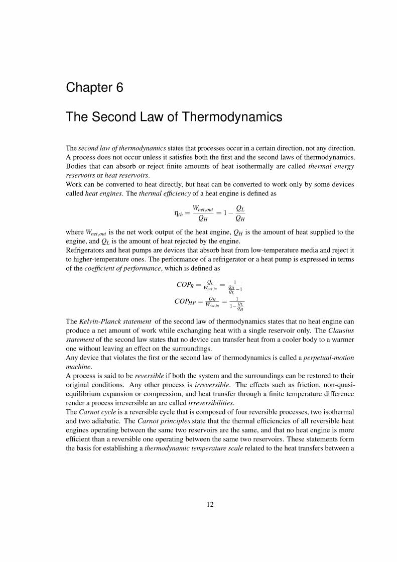
The Second Law of Thermodynamics
The second law of thermodynamics states that processes occur in a certain direction, not any direction.A process does not occur unless it satisfies both the first and the second laws of thermodynamics.Bodies that can absorb or reject finite amounts of heat isothermally are called thermal energyreservoirs or heat reservoirs.Work can be converted to heat directly, but heat can be converted to work only by some devicescalled heat engines. The thermal efficiency of a heat engine is defined as
ηth =Wnet,out
QH= 1− QL
QH
where Wnet,out is the net work output of the heat engine, QH is the amount of heat supplied to theengine, and QL is the amount of heat rejected by the engine.Refrigerators and heat pumps are devices that absorb heat from low-temperature media and reject itto higher-temperature ones. The performance of a refrigerator or a heat pump is expressed in termsof the coefficient of performance, which is defined as
COPR = QLWnet,in
= 1QHQL−1
COPHP = QHWnet,in
= 11− QL
QH
The Kelvin-Planck statement of the second law of thermodynamics states that no heat engine canproduce a net amount of work while exchanging heat with a single reservoir only. The Clausiusstatement of the second law states that no device can transfer heat from a cooler body to a warmerone without leaving an effect on the surroundings.Any device that violates the first or the second law of thermodynamics is called a perpetual-motionmachine.A process is said to be reversible if both the system and the surroundings can be restored to theiroriginal conditions. Any other process is irreversible. The effects such as friction, non-quasi-equilibrium expansion or compression, and heat transfer through a finite temperature differencerender a process irreversible an are called irreversibilities.The Carnot cycle is a reversible cycle that is composed of four reversible processes, two isothermaland two adiabatic. The Carnot principles state that the thermal efficiencies of all reversible heatengines operating between the same two reservoirs are the same, and that no heat engine is moreefficient than a reversible one operating between the same two reservoirs. These statements formthe basis for establishing a thermodynamic temperature scale related to the heat transfers between a
12

reversible device and the high- and low-temperature reservoirs by(QH
QL
)rev
=TH
TH
therefore, the QH/QL ratio can be replaced by TH/TL for reversible devices, where TH and TL are theabsolute temperatures of the high- and low-temperature reservoirs, respectively.A heat engine that operates on the reversible Carnot cycle is called a Carnot heat engine. The thermalefficiency of a Carnot heat engine, as well as all other reversible heat engines is given by
ηth,rev = 1− TL
TH
This is the maximum efficiency a heat engine operating between two reservoirs at temperatures TH
and TL can have.The COPs of reversible refrigerators and heat pumps are given in a similar manner as
COPR,rev =1
THTL−1
and
COPHP,rev =1
1− TLTH
Again, these are the highest COPs a refrigerator or a heat pump operating between the temperaturelimits of TH and TL can have.

Chapter 7
Entropy
The second law of thermodynamics leads to the definition of a new property called entropy, which isa quantitative measure of microscopic disorder for a system. Any quantity whose cyclic integral iszero is called a property, and entropy is defined as
dS =
(dQT
)int,rev
For the special case of an internally reversible, isothermal process, it gives
∆S =QT0
The inequality part of the Clausius inequality combined with the definition of entropy yields aninequality known as the increase of entropy principle, expressed as
Sgen ≥ 0
where Sgen is the entropy generated during the process. Entropy change is caused by heat transfer,mass flow, and irreversibilities. Heat transfer to a system increases the entropy, and heat transferfrom a system decreases it. The effect of irreversibilities is always to increase the entropy.The entropy-change and isentropic relations for a process can be summarized as follows
1. Pure substances:
Any process: ∆s = s2− s1
Isentropic process: s2 = s1
2. Incompressible substances:
Any process: s2− s1 = cavg ln T2T1
Isentropic process: T2 = T1
14

3. Ideal gases:
a) Constant specific heats (approximate treatment):
Any process: s2− s1 = cv,avg ln T2T1+R ln v2
v1
s2− s1 = cP,avg ln T2T1+R ln P2
P1
Isentropic process:(
T2T1
)s=constant
=(
v1v2
)k−1
(T2T1
)s=constant
=(
P1P2
) k−1k
(P2P1
)s=constant
=(
v1v2
)k
b) Variable specific heats (exact treatment):
Any process: s2− s1 = s◦2− s◦1−R ln P2P1
Isentropic process: s◦2 = s◦1 +R ln P2P1(
P2P1
)s=constant
= Pr2Pr1(
v2v1
)s=constant
= vr2vr1
Where Pr is the relative pressure and vr is the relative specific volume. The funcion s◦ depends ontemperature only.The steady-flow work for a reversible process can be expressed in terms of the fluid properties as
wrev =−2∫
1
vdP−∆ke−∆pe
For incompressible substances (v = constant) it simplifies to
wrev =−v(P2−P1)−∆ke−∆pe
The work done during a steady-flow process is proportional to the specific volume. Therefore, vshould be kept as small as possible during a compression process to minimize the work input and aslarge as possible during an expansion process to maximize the work output.The reversible work inputs to a compressor compressing an ideal gas from T1, P1 to P2 in an isentropic(Pvk = constant), polytropic (Pvn = constant) or isothermal (Pv = constant) manner, are determinedby integration for each case with the following results:
Isentropic: wcomp,in =kR(T2−T1)
k−1 = kRT1k−1
[(P2P1
) k−1k −1
]Polytropic: wcomp,in =
nR(T2−T1)n−1 = nRT1
n−1
[(P2P1
) n−1n −1
]Isothermal: wcomp,in = RT ln P2
P1

The work input to a compressor can be reduced by using multistage compression with intercooling.For maximum savings from the work input, the pressure ratio across each stage of the compressormust be the same.Most steady-flow devices operate under adiabatic condtions, and the ideal process for these devicesis the isentropic process. The parameter that describes how efficiently a device approximates acorresponding isentropic device is called isentropic or adiabatic efficiency. It is expressed forturbines, compressors, and nozzles as follows:
ηT = Actual turbine workIsentropic turbine work = wa
ws∼= h1−h2a
h1−h2s
ηC = Isentropic compressor workActual compressor work = ws
wa∼= h2s−h1
h2a−h1
ηN = Actual KE at nozzle exitIsentropic KE at nozzle exit =
V 22a
V 22s
∼= h1−h2ah1−h2s
In the relations above, h2a and h2s are the enthalpy values at the exit state for actual and isentropicprocesses, respectively.The entropy balance for any system undergoing any process can be expressed in the general formas
Sin−Sout︸ ︷︷ ︸Net entropy transfer by heat and mass
+ Sgen︸︷︷︸Entropy generation
= ∆Ssystem︸ ︷︷ ︸Change in entropy
or, in rate form, as
Sin− Sout︸ ︷︷ ︸Rate of net entropy transfer by heat and mass
+ Sgen︸︷︷︸Rate of entropy generation
=dSsystem
dt︸ ︷︷ ︸Rate of change in entropy
For a general stead-flow process it simplifies to
Sgen = ∑ mese−∑ misi−∑Qk
Tk

Chapter 8
Exergy: A Measure of Work Potentional
Not mandatory for the exam
17
Chapter 9
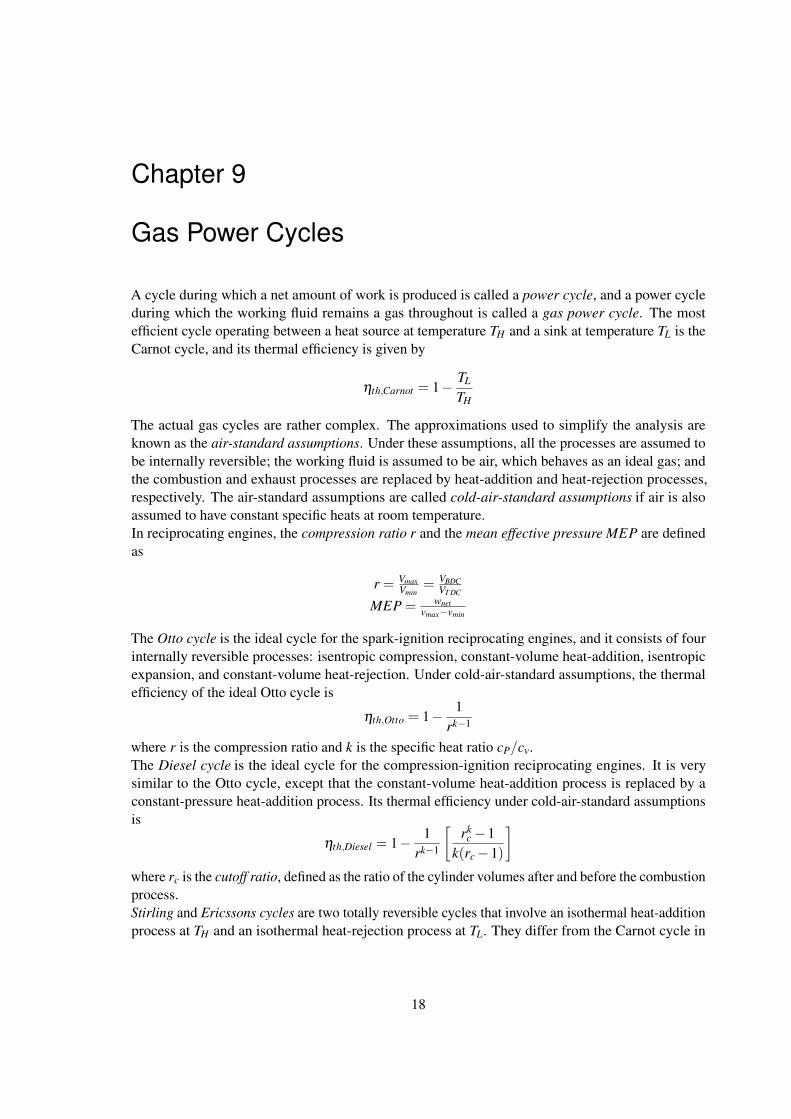
Gas Power Cycles
A cycle during which a net amount of work is produced is called a power cycle, and a power cycleduring which the working fluid remains a gas throughout is called a gas power cycle. The mostefficient cycle operating between a heat source at temperature TH and a sink at temperature TL is theCarnot cycle, and its thermal efficiency is given by
ηth,Carnot = 1− TL
TH
The actual gas cycles are rather complex. The approximations used to simplify the analysis areknown as the air-standard assumptions. Under these assumptions, all the processes are assumed tobe internally reversible; the working fluid is assumed to be air, which behaves as an ideal gas; andthe combustion and exhaust processes are replaced by heat-addition and heat-rejection processes,respectively. The air-standard assumptions are called cold-air-standard assumptions if air is alsoassumed to have constant specific heats at room temperature.In reciprocating engines, the compression ratio r and the mean effective pressure MEP are definedas
r = VmaxVmin
= VBDCVT DC
MEP = wnetvmax−vmin
The Otto cycle is the ideal cycle for the spark-ignition reciprocating engines, and it consists of fourinternally reversible processes: isentropic compression, constant-volume heat-addition, isentropicexpansion, and constant-volume heat-rejection. Under cold-air-standard assumptions, the thermalefficiency of the ideal Otto cycle is
ηth,Otto = 1− 1rk−1
where r is the compression ratio and k is the specific heat ratio cP/cv.The Diesel cycle is the ideal cycle for the compression-ignition reciprocating engines. It is verysimilar to the Otto cycle, except that the constant-volume heat-addition process is replaced by aconstant-pressure heat-addition process. Its thermal efficiency under cold-air-standard assumptionsis
ηth,Diesel = 1− 1rk−1
[rk
c−1k(rc−1)
]where rc is the cutoff ratio, defined as the ratio of the cylinder volumes after and before the combustionprocess.Stirling and Ericssons cycles are two totally reversible cycles that involve an isothermal heat-additionprocess at TH and an isothermal heat-rejection process at TL. They differ from the Carnot cycle in
18
that the two isentropic processes are replaced by two constant-volume regeneration processes in theStirling cycle and by two constant-pressure regeneration processes in the Ericsson cycle. Both cyclesutilize regeneration, a process during which heat is transferred to a thermal energy storage device(called a regenerator) during one part of the cycle that is then transferred back to the working fluidduring another part of the cycle.The ideal cycle for modern gas-turbine engines is the Brayton cycle, which is made up of fourinternally reversible processes: isentropic compression, constant-pressure heat-addition, isentropicexpansion, and constant-pressure heat-rejection. Under cold-air-standard assumptions, its thermalefficiency is
ηth,Brayton = 1− 1
r(k−1)/kp
where rP = Pmax/Pmin is the pressure ratio and k is the specific heat ratio. The thermal efficiency ofthe simple Brayton cycle increases with the pressure ratio.The deviation of the actual compressor and the turbine from the idealize isentropic ones can beaccurately accounted for by utilizing their isentropic efficiencies, defined as
ηC = wswa∼= h2s−h1
h2a−h1
and
ηT = waws∼= h3−h4a
h3−h4S
where states 1 and 3 are the inlet states, 2a and 4a are the actual exit states, and 2s and 4s are theisentropic exit states.In gas-turbine engines, the temperature of the exhaust gas leaving the turbine is often considerablyhigher than the temperature of the air leaving the compressor. Therefore, the high-pressure air leavingthe compressor can be heated by transferring heat to it from the hot exhaust gases in a counter-flowheat exchanger, which is also known as a regenerator. The extent to which a regenerator approachesan ideal regenerator is called the effectiveness ε and is defined as
ε =qregen,act
qregen,max
Under cold-air-standard assumptions, the thermal efficiency of an ideal Brayton cycle with regenera-tion becomes
ηth,regen = 1−(
T1
T3
)(rP)
k−1k
where T1 and T3 are the minimum and maximum temperatures, respectively, in the cycle.The thermal efficiency of the Brayton cycle can also be increased by utilizing multistage compressionwith intercooling, regeneration, and multistage expansion with reheating. The work input to thecompressor is minimized when equal pressure ratios are maintained across each stage. This procedurealso maximizes the turbine work output.Gas-turbine engines are widely used to power aircraft because they are light and compact and have ahigh power-to-weight ratio. The ideal jet-propulsion cycle differs from the simple ideal Brayton cyclein that the gases are partially expanded in the turbine. The gases that exit the turbine at a relativelyhigh pressure are subsequently accelerated in a nozzle to provide the thrust needed to propel theaircraft.The net thrust developed by the engine is
F = m(Vexit −Vinlet)
where m is the mass flow rate of gases, Vexit is the exit velocity of the exhaust gases, and Vinlet is theinlet velocity of the air, both relative to the aircraft.The power developed from the thrust of the engine is called the propulsive power Wp, and it is givenby
WP = m(Vexit −Vinlet)Vaircra f t
Propulsive efficiency is a measure of how efficiently the energy released during the combustionprocess is converted to propulsive energy, and it is defined as
ηP =Propulsive powerEnergy input rate
=WP
Qin
For an ideal cycle that involves heat transfer only with a source at TH and a sink at TL, the exergydestruction is
xdest = T0
(qout
TL− qin
TH
)