Suggested Test Equipment for Radiology Quality Control
17
Test Equipment for Radiology and CT Quality Control Contents Quality Control Testing ............................................................................................................... 2 Photometers for Digital Clinical Display QC .............................................................................. 3 Primary Workstations.............................................................................................................. 3 Secondary Workstations......................................................................................................... 3 Testing of workstations .......................................................................................................... 3 Dosemeters.................................................................................................................................. 4 Dosimetry Phantoms .................................................................................................................. 5 Radiography Dosimetry Phantoms ........................................................................................ 5 Radioscopy Dosimetry Phantoms.......................................................................................... 5 CT Dosimetry Phantoms ......................................................................................................... 6 Image Quality Phantoms ............................................................................................................ 8 Radiography Image Quality Phantoms .................................................................................. 8 Leeds Phantom TO20 .............................................................................................................. 9 Leeds Phantom TOR CDR..................................................................................................... 10 Artinis CDRAD Phantom ....................................................................................................... 11 Conventional and Digital Radioscopy ................................................................................. 13 CT Image Quality Phantoms ................................................................................................. 14 Equipment List for Annual QC Testing ................................................................................... 16
Transcript of Suggested Test Equipment for Radiology Quality Control
Test Equipment for Radiology and CT Quality Control
Contents
Quality Control Testing ...............................................................................................................2
Photometers for Digital Clinical Display QC..............................................................................3
Primary Workstations..............................................................................................................3
Secondary Workstations.........................................................................................................3
Testing of workstations ..........................................................................................................3
Dosemeters..................................................................................................................................4
Dosimetry Phantoms ..................................................................................................................5
Radiography Dosimetry Phantoms........................................................................................5
Radioscopy Dosimetry Phantoms..........................................................................................5
CT Dosimetry Phantoms .........................................................................................................6
Image Quality Phantoms ............................................................................................................8
Radiography Image Quality Phantoms..................................................................................8
Leeds Phantom TO20 ..............................................................................................................9
Leeds Phantom TOR CDR.....................................................................................................10
Artinis CDRAD Phantom .......................................................................................................11
Conventional and Digital Radioscopy .................................................................................13
CT Image Quality Phantoms .................................................................................................14
Equipment List for Annual QC Testing ...................................................................................16
Quality Control Testing in SC 35 Image quality is stressed for all imaging systems in Safety Code 35. In the relevant sections Health Canada’s advice is “ the manufacturer’s recommended test procedures must be followed…” If manufacturers’ tests or phantoms are used by the manufacturers themselves or in-house staff, there should be quantifiable measurements which can be used to track performance. If manufacturers’ QC phantoms and test procedures are not available the alternative QC methods described in these documents should be used. Note: for all QC measurements ensure that all required calibrations and PMs have been completed at the designated intervals before any testing. Caution: Observe radiation safety precautions when making radiation exposures. In radiographic and CT scanner rooms always make exposures from the control area. With radioscopic equipment always wear a lead apron. Ensure you are wearing a personal dosimeter.
Photometers for Digital Clinical Display QC The AAPM document TG18 gives interesting insights into the properties of medical displays, and suggest many tests which can be made on them. Briefly, two types of display are described Primary Workstations: those used for medical interpretation of all digital images (excluding mammography) Requirements: Contrast 250:1 Minimum luminance 170 cd/m2 Requirements for mammography are not included, see the DAP Mammography Accreditation Standards for primary display systems. In order to achieve such a contrast ratio the light from any sources such as windows, doors, lamps etc must be decreased, and reflections from light clothing should be avoided. Secondary Workstations: those used for the display of images other than for medical interpretation Requirements: Contrast 100:1 Minimum luminance 100 cd/m2 This level is easier to achieve by reduced room lighting.
Testing of workstations Two types of photometer are typically used. Many display system have calibration software which uses an external photometer (‘puck’) on the screen surface to sense various displayed patterns and set up contrast a colour temperature. Note that this type of puck does not measure reflected light. For systems which have no such software, telescopic systems such as the Minolta can be used. The telescope is focused on a pattern such as the SMPTE and the density levels measured. This type of photometer does include reflected light so for accurate measurements, stray light sources should be eliminated.
Dosemeters Physicists often tend to favour ionization chamber detectors over other detectors for absolute dose measurements, because the response of such detectors is almost constant over a wide energy range, often from 40 keV to 10 MeV. However, they have some disadvantages. They can be damaged by mechanical shock, they require a chamber potential of a few hundred volts, and they have low sensitivity, so large ion chambers are required to measure low doses, such as for shielding measurements. Also the very wide energy response itself can be a detriment in some radiological measurements, as primary and scattered radiation will be recorded with equal sensitivity. As many ion chambers have an isotropic response, scatter will be recorded from any direction with equal sensitivity. In recent years several companies have developed semiconductor radiation detectors which can measure several characteristics of the x-ray beam including radiation dose, kVp, time and, in some case the HVL and the radiation waveform. All use several semiconductor detectors with different attenuators to achieve this. Unlike ionization chambers the response of semiconductors with energy is very non-uniform, so that the meters have inbuilt computers that compensate for this. Like ion chambers semiconductor devices measure air kerma dose. However, unlike ion chambers these detectors have a very directional response and are much less affected by scatter. Whatever type of meter is chosen, be aware of the limitations of the meter, such as Can the meter be used immediately or is a stabilization period required? Will the first measurement be accurate, or does the meter need test exposures Is there a dose or dose-rate limitation? Does the kVp reading depend upon the filtration in the x-ray tube and collimator? When using an ion chamber are there any surfaces within 30 cm which will affect the reading? It is recommended that meters be calibrated at least every two years. Many hospitals and clinics will have several dose meters. In this case, it is recommended that at least one meter be calibrated at National Research Council Labs in Ottawa or by the manufacturer every year, and the other meters cross-calibrated.
Dosimetry Phantoms
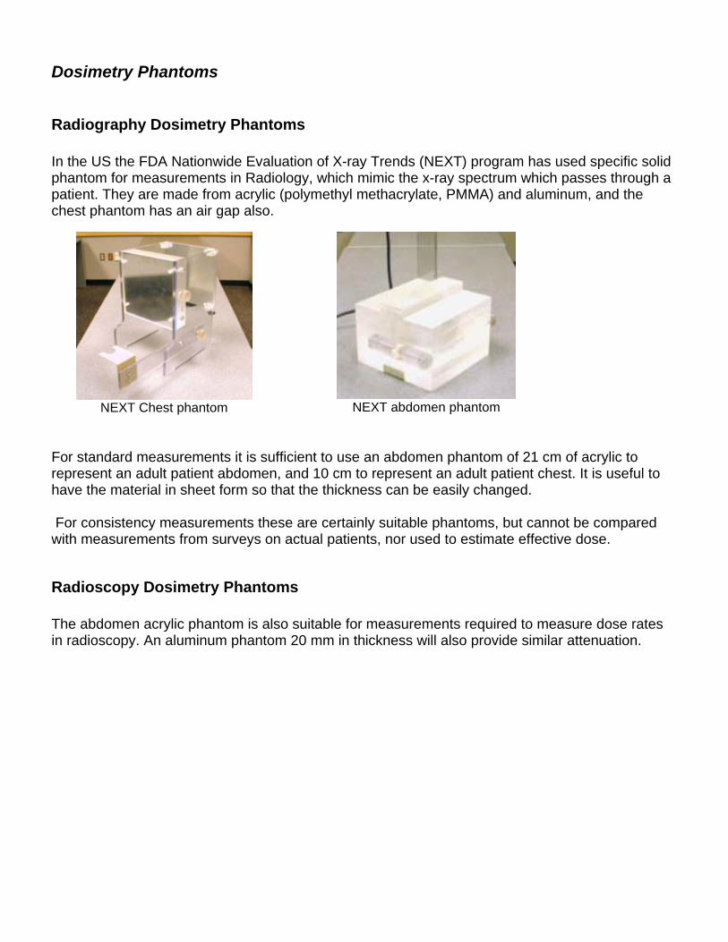
Radiography Dosimetry Phantoms In the US the FDA Nationwide Evaluation of X-ray Trends (NEXT) program has used specific solid phantom for measurements in Radiology, which mimic the x-ray spectrum which passes through a patient. They are made from acrylic (polymethyl methacrylate, PMMA) and aluminum, and the chest phantom has an air gap also.
NEXT Chest phantom
NEXT abdomen phantom
For standard measurements it is sufficient to use an abdomen phantom of 21 cm of acrylic to represent an adult patient abdomen, and 10 cm to represent an adult patient chest. It is useful to have the material in sheet form so that the thickness can be easily changed. For consistency measurements these are certainly suitable phantoms, but cannot be compared with measurements from surveys on actual patients, nor used to estimate effective dose.
Radioscopy Dosimetry Phantoms The abdomen acrylic phantom is also suitable for measurements required to measure dose rates in radioscopy. An aluminum phantom 20 mm in thickness will also provide similar attenuation.
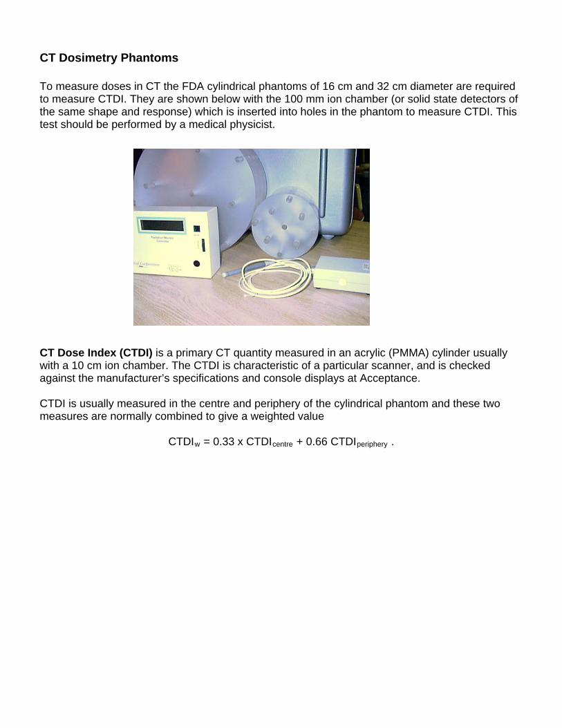
CT Dosimetry Phantoms To measure doses in CT the FDA cylindrical phantoms of 16 cm and 32 cm diameter are required to measure CTDI. They are shown below with the 100 mm ion chamber (or solid state detectors of the same shape and response) which is inserted into holes in the phantom to measure CTDI. This test should be performed by a medical physicist. CT Dose Index (CTDI) is a primary CT quantity measured in an acrylic (PMMA) cylinder usually with a 10 cm ion chamber. The CTDI is characteristic of a particular scanner, and is checked against the manufacturer’s specifications and console displays at Acceptance. CTDI is usually measured in the centre and periphery of the cylindrical phantom and these two measures are normally combined to give a weighted value
CTDIw = 0.33 x CTDIcentre + 0.66 CTDIperiphery .
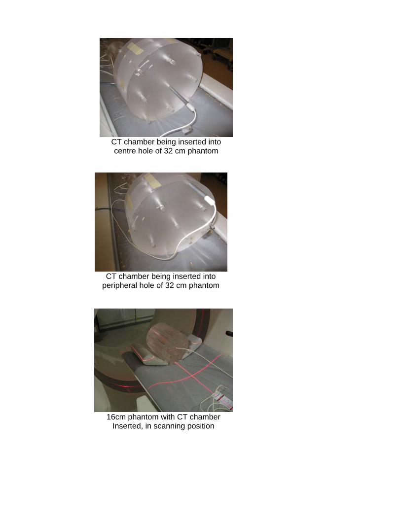
CT chamber being inserted into centre hole of 32 cm phantom
CT chamber being inserted into
peripheral hole of 32 cm phantom
16cm phantom with CT chamber
Inserted, in scanning position
Image Quality Phantoms
Radiography Image Quality Phantoms All manufacturers have image quality phantoms and test procedures for use with CR and DR systems. As recommended by SC 35 these should be used if the test procedures produce quantitative information which can be used to monitor performance. Otherwise the phantoms described below can be used. For radiography two types of contrast-detail phantoms have been commonly used – the Leeds series of phantoms (www.leedstestobjects.com ) and the CDRAD phantom (www.artinis.com ). Both types of phantom contain objects of known diameter and contrast and the lowest contrast of each size which can be visualized under standard conditions can be used as measure of quality. Until recently reproducible ‘reading’ of images of these phantoms has been difficult, but now software is available to evaluate the DICOM images produced using the phantoms. Recently it has been shown that software evaluation of the CDRAD phantom closely matches that of a human observer (Pascoal A, Lawinski CP Honey I and Blake P Physics in Medicine and Biology 2005 50:5743-5757).
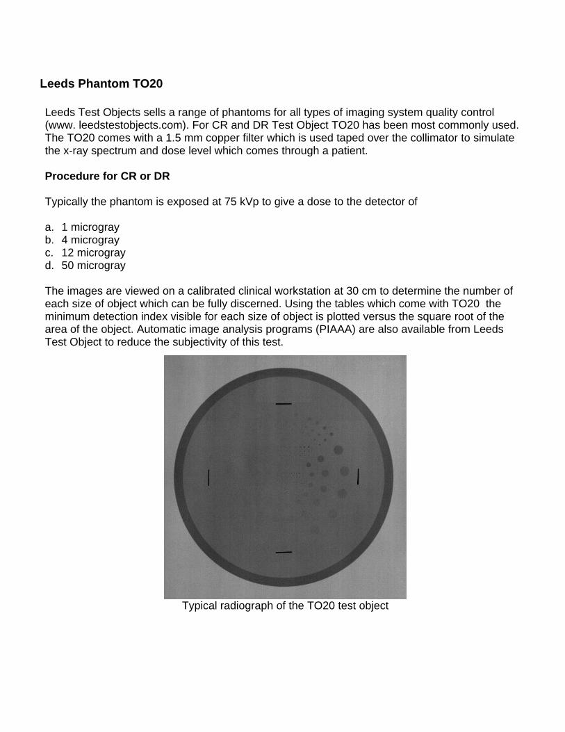
Leeds Phantom TO20 Leeds Test Objects sells a range of phantoms for all types of imaging system quality control (www. leedstestobjects.com). For CR and DR Test Object TO20 has been most commonly used. The TO20 comes with a 1.5 mm copper filter which is used taped over the collimator to simulate the x-ray spectrum and dose level which comes through a patient. Procedure for CR or DR Typically the phantom is exposed at 75 kVp to give a dose to the detector of a. 1 microgray b. 4 microgray c. 12 microgray d. 50 microgray
The images are viewed on a calibrated clinical workstation at 30 cm to determine the number of each size of object which can be fully discerned. Using the tables which come with TO20 the minimum detection index visible for each size of object is plotted versus the square root of the area of the object. Automatic image analysis programs (PIAAA) are also available from Leeds Test Object to reduce the subjectivity of this test.
Typical radiograph of the TO20 test object
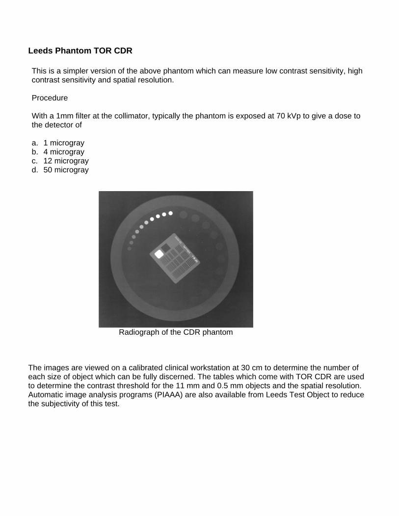
Leeds Phantom TOR CDR This is a simpler version of the above phantom which can measure low contrast sensitivity, high contrast sensitivity and spatial resolution. Procedure With a 1mm filter at the collimator, typically the phantom is exposed at 70 kVp to give a dose to the detector of a. 1 microgray b. 4 microgray c. 12 microgray d. 50 microgray
Radiograph of the CDR phantom
The images are viewed on a calibrated clinical workstation at 30 cm to determine the number of each size of object which can be fully discerned. The tables which come with TOR CDR are used to determine the contrast threshold for the 11 mm and 0.5 mm objects and the spatial resolution. Automatic image analysis programs (PIAAA) are also available from Leeds Test Object to reduce the subjectivity of this test.
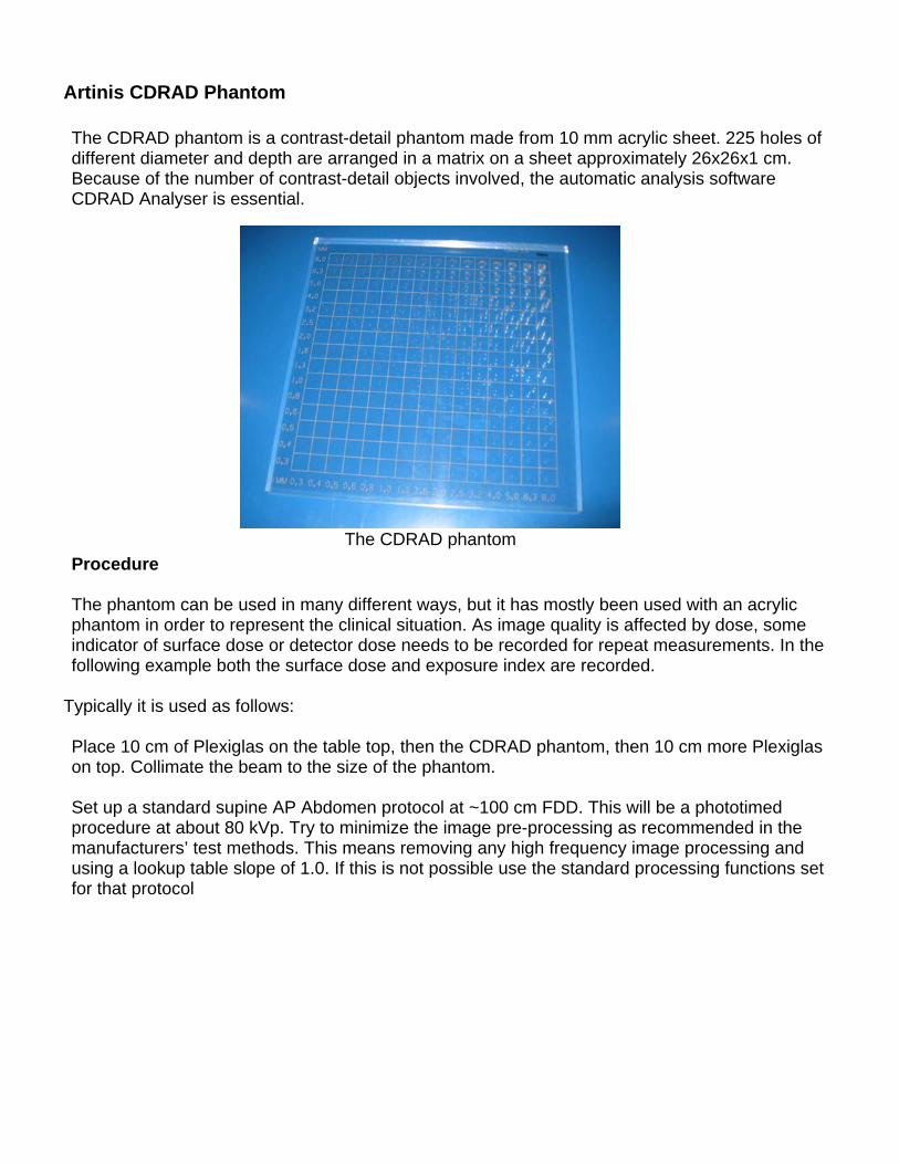
Artinis CDRAD Phantom The CDRAD phantom is a contrast-detail phantom made from 10 mm acrylic sheet. 225 holes of different diameter and depth are arranged in a matrix on a sheet approximately 26x26x1 cm. Because of the number of contrast-detail objects involved, the automatic analysis software CDRAD Analyser is essential.
The CDRAD phantom
Procedure The phantom can be used in many different ways, but it has mostly been used with an acrylic phantom in order to represent the clinical situation. As image quality is affected by dose, some indicator of surface dose or detector dose needs to be recorded for repeat measurements. In the following example both the surface dose and exposure index are recorded.
Typically it is used as follows: Place 10 cm of Plexiglas on the table top, then the CDRAD phantom, then 10 cm more Plexiglas on top. Collimate the beam to the size of the phantom. Set up a standard supine AP Abdomen protocol at ~100 cm FDD. This will be a phototimed procedure at about 80 kVp. Try to minimize the image pre-processing as recommended in the manufacturers’ test methods. This means removing any high frequency image processing and using a lookup table slope of 1.0. If this is not possible use the standard processing functions set for that protocol
CDRAD phantom between two 10 cm slabs
Of acrylic
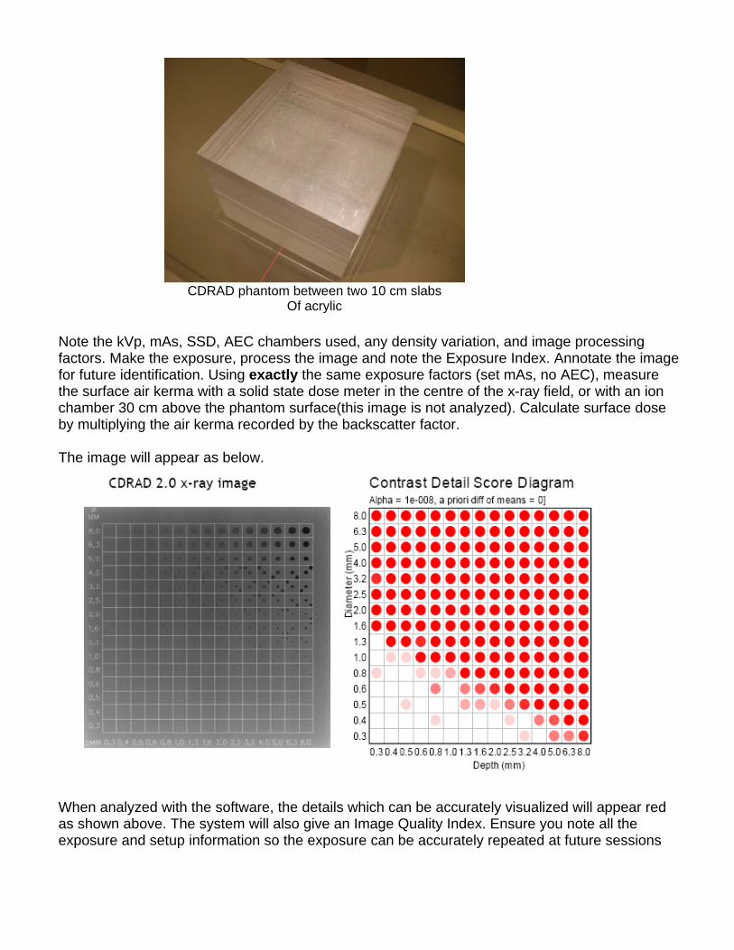
Note the kVp, mAs, SSD, AEC chambers used, any density variation, and image processing factors. Make the exposure, process the image and note the Exposure Index. Annotate the image for future identification. Using exactly the same exposure factors (set mAs, no AEC), measure the surface air kerma with a solid state dose meter in the centre of the x-ray field, or with an ion chamber 30 cm above the phantom surface(this image is not analyzed). Calculate surface dose by multiplying the air kerma recorded by the backscatter factor. The image will appear as below.
When analyzed with the software, the details which can be accurately visualized will appear red as shown above. The system will also give an Image Quality Index. Ensure you note all the exposure and setup information so the exposure can be accurately repeated at future sessions
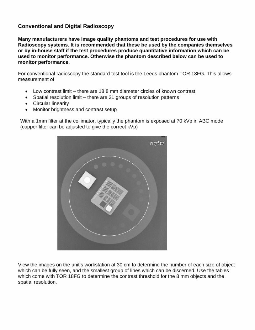
Conventional and Digital Radioscopy Many manufacturers have image quality phantoms and test procedures for use with Radioscopy systems. It is recommended that these be used by the companies themselves or by in-house staff if the test procedures produce quantitative information which can be used to monitor performance. Otherwise the phantom described below can be used to monitor performance. For conventional radioscopy the standard test tool is the Leeds phantom TOR 18FG. This allows measurement of
Low contrast limit – there are 18 8 mm diameter circles of known contrast Spatial resolution limit – there are 21 groups of resolution patterns Circular linearity Monitor brightness and contrast setup
With a 1mm filter at the collimator, typically the phantom is exposed at 70 kVp in ABC mode (copper filter can be adjusted to give the correct kVp)
View the images on the unit’s workstation at 30 cm to determine the number of each size of object which can be fully seen, and the smallest group of lines which can be discerned. Use the tables which come with TOR 18FG to determine the contrast threshold for the 8 mm objects and the spatial resolution.
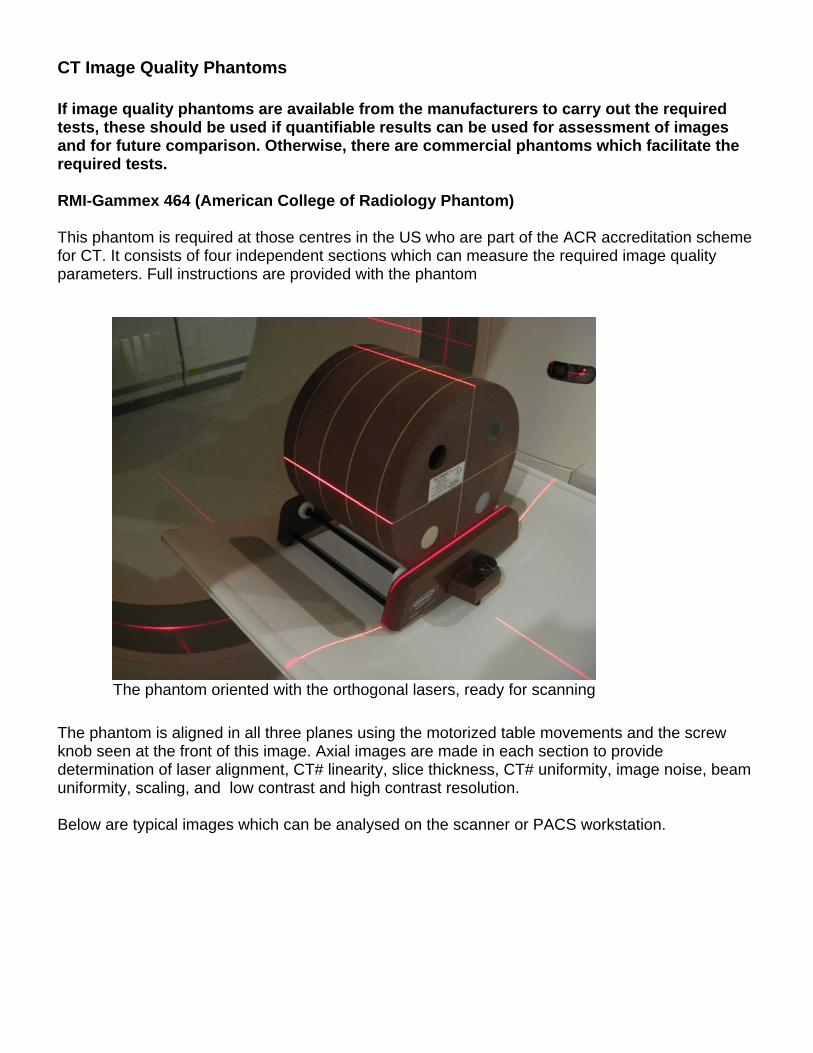
CT Image Quality Phantoms If image quality phantoms are available from the manufacturers to carry out the required tests, these should be used if quantifiable results can be used for assessment of images and for future comparison. Otherwise, there are commercial phantoms which facilitate the required tests. RMI-Gammex 464 (American College of Radiology Phantom) This phantom is required at those centres in the US who are part of the ACR accreditation scheme for CT. It consists of four independent sections which can measure the required image quality parameters. Full instructions are provided with the phantom
The phantom oriented with the orthogonal lasers, ready for scanning
The phantom is aligned in all three planes using the motorized table movements and the screw knob seen at the front of this image. Axial images are made in each section to provide determination of laser alignment, CT# linearity, slice thickness, CT# uniformity, image noise, beam uniformity, scaling, and low contrast and high contrast resolution. Below are typical images which can be analysed on the scanner or PACS workstation.
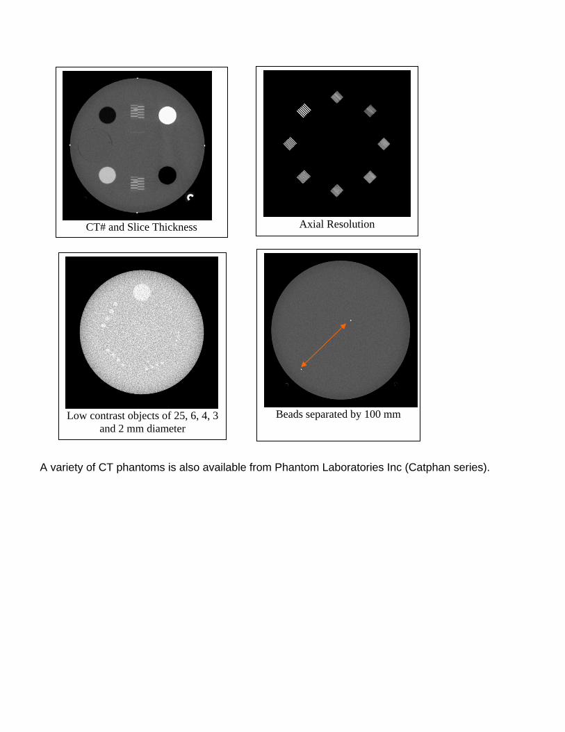
Axial Resolution
CT# and Slice Thickness
Beads separated by 100 mm
Low contrast objects of 25, 6, 4, 3
and 2 mm diameter
A variety of CT phantoms is also available from Phantom Laboratories Inc (Catphan series).
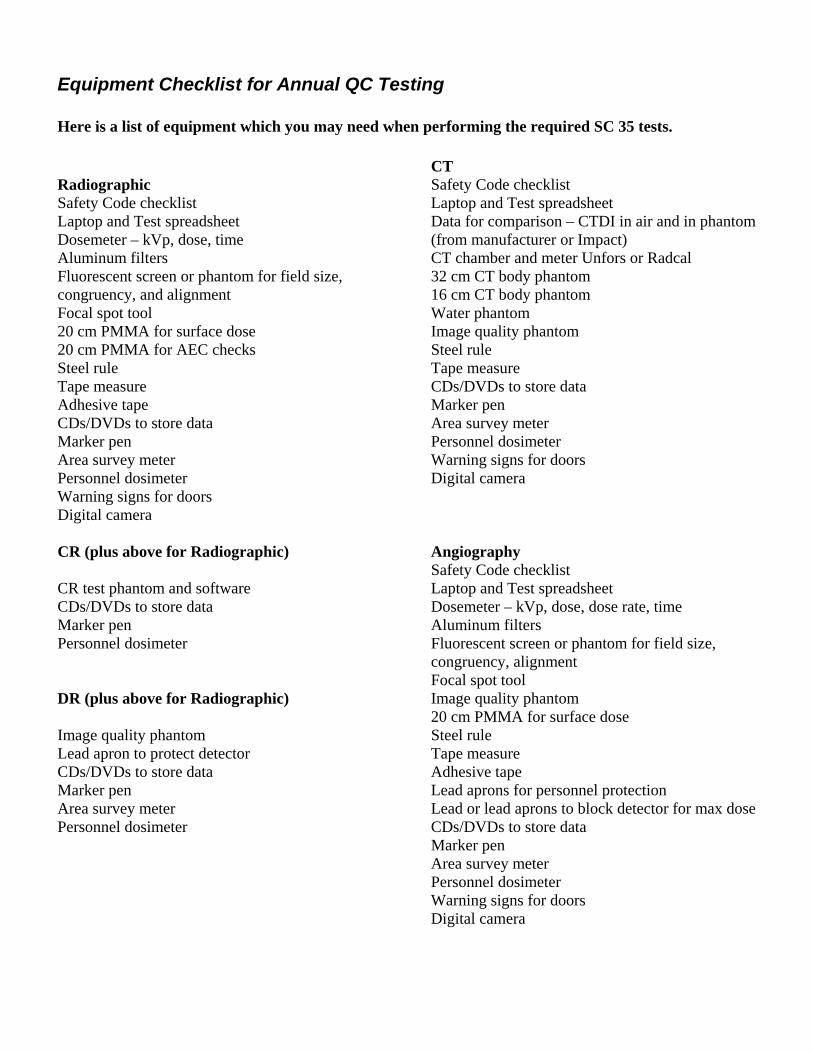
Equipment Checklist for Annual QC Testing Here is a list of equipment which you may need when performing the required SC 35 tests.
Radiographic Safety Code checklist Laptop and Test spreadsheet Dosemeter – kVp, dose, time Aluminum filters Fluorescent screen or phantom for field size, congruency, and alignment Focal spot tool 20 cm PMMA for surface dose 20 cm PMMA for AEC checks Steel rule Tape measure Adhesive tape CDs/DVDs to store data Marker pen Area survey meter Personnel dosimeter Warning signs for doors Digital camera CR (plus above for Radiographic) CR test phantom and software CDs/DVDs to store data Marker pen Personnel dosimeter DR (plus above for Radiographic) Image quality phantom Lead apron to protect detector CDs/DVDs to store data Marker pen Area survey meter Personnel dosimeter
CT Safety Code checklist Laptop and Test spreadsheet Data for comparison – CTDI in air and in phantom (from manufacturer or Impact) CT chamber and meter Unfors or Radcal 32 cm CT body phantom 16 cm CT body phantom Water phantom Image quality phantom Steel rule Tape measure CDs/DVDs to store data Marker pen Area survey meter Personnel dosimeter Warning signs for doors Digital camera Angiography Safety Code checklist Laptop and Test spreadsheet Dosemeter – kVp, dose, dose rate, time Aluminum filters Fluorescent screen or phantom for field size, congruency, alignment Focal spot tool Image quality phantom 20 cm PMMA for surface dose Steel rule Tape measure Adhesive tape Lead aprons for personnel protection Lead or lead aprons to block detector for max dose CDs/DVDs to store data Marker pen Area survey meter Personnel dosimeter Warning signs for doors Digital camera