SUCTION FILTER Series AS 220 DN 40 - 50 1903...
16
SUCTION FILTER Series AS 220 DN 40 - 50 Sheet No. 1903 G 1. Type index: 1.1. Complete filter: (ordering example) AS. 220. 40G. -. B. P. -. FS. 8. -. O1. - 1 2 3 4 5 6 7 8 9 10 11 12 1 series: AS = suction filter 2 nominal size: 220 3 filter-material and filter-fineness: 80 G= 80 μm, 40 G= 40 μm stainless steel wire mesh, other materials on request 4 resistance of pressure difference for filter element: - = not specified 5 filter element design: B = both sides open 6 sealing material: P = Nitrile (NBR) V = Viton (FPM) 7 filter element specification: - = standard VA = stainless steel 8 connection: FS = SAE-flange connection 3000 PSI 9 no. of version: version 7 4 8 connection A type - FS FS size - 7 7 connection B type FS - FS size 8 - 8 type: FS = SAE-flange 3000 PSI size: - = no connection 7 = 1 ½ “ 8 = 2 “ 10 filter housing specification: - = standard 11 clogging indicator at M1: - = without O1 = visual, see sheet-no. 1616 E4.-0,25 = pressure switch, see sheet-no. 1616 12 clogging indicator at M2: possible indicators see position 11 of the type index 1.2. Filter element: (ordering example) 01AS. 220. 40G. -. B -. - 1 2 3 4 5 6 7 1 series: 01AS. = suction filter element according to INTERNORMEN factory specification 2 nominal size: 220 3 - 5 , 7 see type index complete-filter 6 sealing material: - = without 2. Accessories: - counter flange see sheet-no. 1652 mounting area surface quality flatness tolerance weight: approx. 4,5 kg Changes of measures and design are subject to alteration! EDV 11/07 +49 - (0)6205 - 2094-0 +49 - (0)6205 - 2094-40 phone fax Friedensstrasse 41, 68804 Altlussheim, Germany e-mail url [email protected] www.internormen.com
Transcript of SUCTION FILTER Series AS 220 DN 40 - 50 1903...

SUCTION FILTERSeries AS 220 DN 40 - 50
Sheet No.
1903 G
1. Type index:
1.1. Complete filter: (ordering example)
AS. 220. 40G. -. B. P. -. FS. 8. -. O1. -1 2 3 4 5 6 7 8 9 10 11 12
1 series:
AS = suction filter
2 nominal size: 220
3 filter-material and filter-fineness:
80 G= 80 µm, 40 G= 40 µm stainless steel wire mesh, other materials on request4 resistance of pressure difference for filter element:
- = not specified5 filter element design:
B = both sides open6 sealing material:
P = Nitrile (NBR)V = Viton (FPM)
7 filter element specification:
- = standardVA = stainless steel
8 connection:
FS = SAE-flange connection 3000 PSI9 no. of version:
version 7 4 8
connection A type - FS FS
size - 7 7
connection B type FS - FS
size 8 - 8
type: FS = SAE-flange 3000 PSIsize: - = no connection
7 = 1 ½ “8 = 2 “
10 filter housing specification:
- = standard11 clogging indicator at M1:
- = withoutO1 = visual, see sheet-no. 1616E4.-0,25 = pressure switch, see sheet-no. 1616
12 clogging indicator at M2:
possible indicators see position 11 of the type index
1.2. Filter element: (ordering example)
01AS. 220. 40G. -. B -. -1 2 3 4 5 6 7
1 series:
01AS. = suction filter element according toINTERNORMEN factory specification
2 nominal size: 220
3 - 5 , 7 see type index complete-filter
6 sealing material:
- = without
2. Accessories:- counter flange see sheet-no. 1652
mounting area
surface quality
flatness tolerance
weight: approx. 4,5 kg
Changes of measures and design are subject to alteration!
EDV 11/07
+49 - (0)6205 - 2094-0+49 - (0)6205 - 2094-40
phonefax
Friedensstrasse 41, 68804 Altlussheim, Germany
e-mailurl
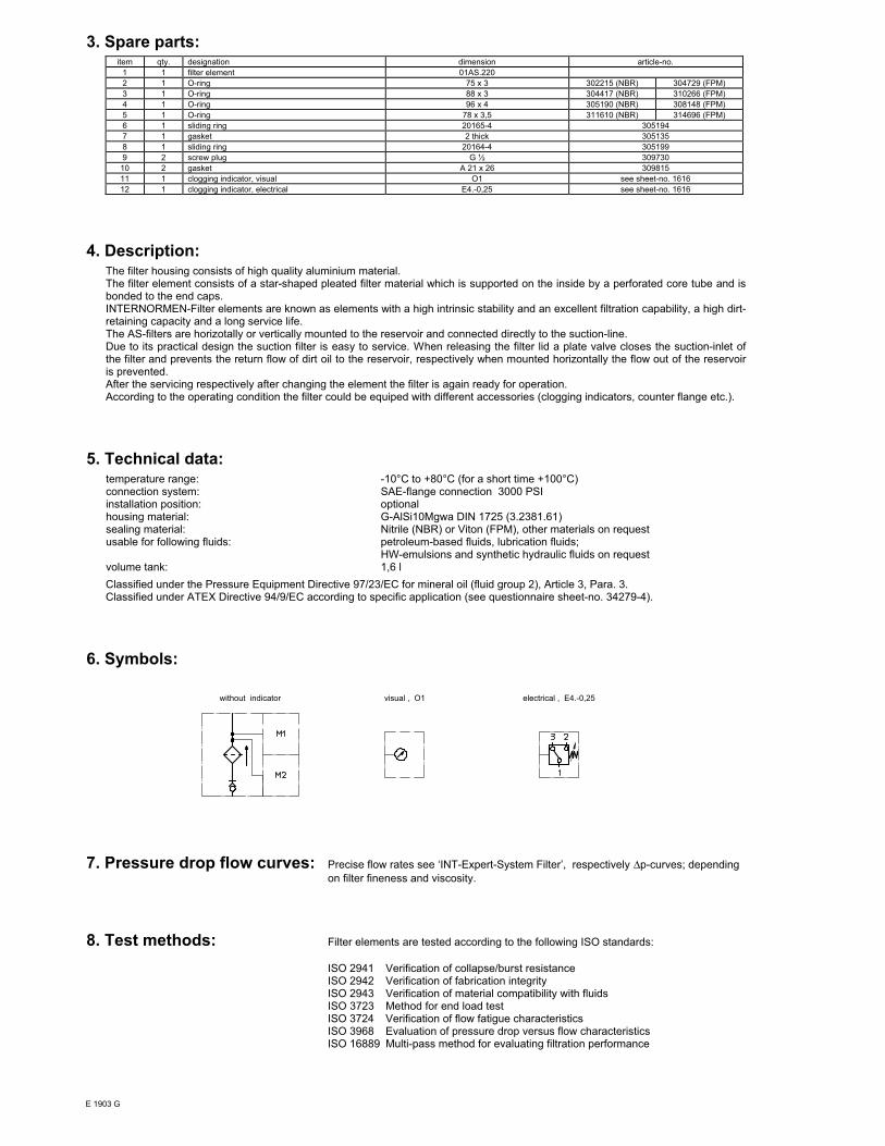
3. Spare parts:item qty. designation dimension article-no.
1 1 filter element 01AS.220
2 1 O-ring 75 x 3 302215 (NBR) 304729 (FPM)
3 1 O-ring 88 x 3 304417 (NBR) 310266 (FPM)
4 1 O-ring 96 x 4 305190 (NBR) 308148 (FPM)
5 1 O-ring 78 x 3,5 311610 (NBR) 314696 (FPM)
6 1 sliding ring 20165-4 305194
7 1 gasket 2 thick 305135
8 1 sliding ring 20164-4 305199
9 2 screw plug G ½ 309730
10 2 gasket A 21 x 26 309815
11 1 clogging indicator, visual O1 see sheet-no. 1616
12 1 clogging indicator, electrical E4.-0,25 see sheet-no. 1616
4. Description:The filter housing consists of high quality aluminium material.The filter element consists of a star-shaped pleated filter material which is supported on the inside by a perforated core tube and isbonded to the end caps.INTERNORMEN-Filter elements are known as elements with a high intrinsic stability and an excellent filtration capability, a high dirt-retaining capacity and a long service life.The AS-filters are horizotally or vertically mounted to the reservoir and connected directly to the suction-line.Due to its practical design the suction filter is easy to service. When releasing the filter lid a plate valve closes the suction-inlet ofthe filter and prevents the return flow of dirt oil to the reservoir, respectively when mounted horizontally the flow out of the reservoiris prevented.After the servicing respectively after changing the element the filter is again ready for operation.According to the operating condition the filter could be equiped with different accessories (clogging indicators, counter flange etc.).
5. Technical data:temperature range: -10°C to +80°C (for a short time +100°C)connection system: SAE-flange connection 3000 PSIinstallation position: optionalhousing material: G-AlSi10Mgwa DIN 1725 (3.2381.61)sealing material: Nitrile (NBR) or Viton (FPM), other materials on requestusable for following fluids: petroleum-based fluids, lubrication fluids;
HW-emulsions and synthetic hydraulic fluids on requestvolume tank: 1,6 l
Classified under the Pressure Equipment Directive 97/23/EC for mineral oil (fluid group 2), Article 3, Para. 3.Classified under ATEX Directive 94/9/EC according to specific application (see questionnaire sheet-no. 34279-4).
6. Symbols:
without indicator visual , O1 electrical , E4.-0,25
7. Pressure drop flow curves: Precise flow rates see ‘INT-Expert-System Filter’, respectively ∆p-curves; depending
on filter fineness and viscosity.
8. Test methods: Filter elements are tested according to the following ISO standards:
ISO 2941 Verification of collapse/burst resistanceISO 2942 Verification of fabrication integrityISO 2943 Verification of material compatibility with fluidsISO 3723 Method for end load testISO 3724 Verification of flow fatigue characteristicsISO 3968 Evaluation of pressure drop versus flow characteristicsISO 16889 Multi-pass method for evaluating filtration performance
E 1903 G
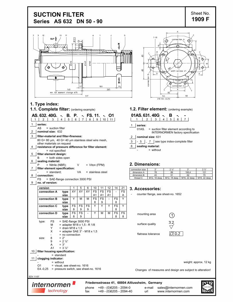
SUCTION FILTERSeries AS 632 DN 50 - 90
Sheet No.
1909 F
1. Type index:
1.1. Complete filter: (ordering example)
AS. 632. 40G. -. B. P. -. FS. 11. -. O11 2 3 4 5 6 7 8 9 10 11
1 series:
AS = suction filter2 nominal size: 632
3 filter-material and filter-fineness:
80 G= 80 µm, 40 G= 40 µm stainless steel wire mesh, other materials on request4 resistance of pressure difference for filter element:
- = not specified5 filter element design:
B = both sides open6 sealing material:
P = Nitrile (NBR); V = Viton (FPM)7 filter element specification:
- = standard; VA = stainless steel8 connection:
FS = SAE-flange connection 3000 PSI9 no. of version:
version 1 5 6 10 11 12 14 21
connection A type XY XY XY FS FS FS - FS
size A1 A1 A1 A
connection B type Y M M FS FS - FS Y
size 8 9 8
connection C type FS FS FS Y Y Y FS Y
size 8 9 9 8
connection D type FS FS - Y M M FS FS
size 8 9 8 8
type: FS = SAE-flange 3000 PSIM = adapter M18 x 1,5 - R 1/8Y = drain M18 x 1,5X = adapter SAE 3“ - M18 x 1,5- = no connection
size: 8 = 2“9 = 2 ½“A = 3“A1 = 3 ½“
10 filter housing specification:
- = standard11 clogging indicator:
- = withoutO1 = visual, see sheet-no. 1616E4.-0,25 = pressure switch, see sheet-no. 1616
1.2. Filter element: (ordering example)
01AS. 631. 40G -. B -. -1 2 3 4 5 6 7
1 series:
01AS. = suction filter element according toINTERNORMEN factory specification
2 nominal size: 631
3 - 5 , 7 see type index-complete filter
6 sealing material:
- = without
2. Dimensions:connection size 2“ 2 ½“ 3“ 3 ½“
dimension A 78 89 106,4 121
dimension B 43 51 62 70
thread C M12, 18 deep M12, 18 deep M16, 22 deep M16, 22 deep
3. Accessories:- counter flange, see sheet-no. 1652
mounting area
surface quality
flatness tolerance
weight: approx. 12 kg
Changes of measures and design are subject to alteration!
EDV 11/07
+49 - (0)6205 - 2094-0+49 - (0)6205 - 2094-40
phonefax
Friedensstrasse 41, 68804 Altlussheim, Germany
e-mailurl

4. Spare parts:item qty. designation dimension article-no.
1 1 filter element 01AS.631
2 1 O-ring 115 x 3 303963 (NBR) 307762 (FPM)
3 1 O-ring 125 x 3 306025 (NBR) 307358 (FPM)
4 1 O-ring 115 x 5 306640 (NBR) 310287 (FPM)
5 1 O-ring 104,37 x 3,53 304339 (NBR) 304390 (FPM)
6 1 gasket 2 thick 305160
7 1 adapter M18 x 1,5 - R 1/8 30505-4 317114
8 2 gasket A18 x 24x1,5 305136
9 1 clogging indicator, visual O1 301722
10 1 clogging indicator, electrical E4.-0,25 301725
11 1 O-ring 85,32 x 3,53 305590 (NBR) 306308 (FPM)
12 1 adapter SAE 3“ - M18 x 1,5 30294-3 317048
13 1 screw plug M18 x 1,5 305193
5. Description:The filter element consists of a star-shaped pleated filter material which is supported on the inside by a perforated core tube and isbonded to the end caps.INTERNORMEN-Filter elements are known as elements with a high intrinsic stability and an excellent filtration capability, a high dirt-retaining capacity and a long service life.The AS-filters are horizotally or vertically mounted to the reservoir and connected directly to the suction-line.Due to its practical design the suction filter is easy to service. When releasing the filter lid a plate valve closes the suction-inlet ofthe filter and prevents the return flow of dirt oil to the reservoir, respectively when mounted horizontally the flow out of the reservoiris prevented.After the servicing respectively after changing the element the filter is again ready for operation.According to the operating condition the filter could be equiped with different accessories (clogging indicators, counter flange etc.).
6. Technical data:temperature range: -10°C to + 80°C (for a short time + 100°C)connection system: SAE-flange connection 3000 PSIinstallation position: optionalhousing material: G-AlSi10Mg wa DIN 1725 (3.2381.61)sealing material: Nitrile (NBR) or Viton (FPM), other materials on requestusable for following fluids: petroleum-based fluids, lubrication fluids;
HW-emulsions and synthetic hydraulic fluids on requestvolume tank: 6,3 l
Classified under the Pressure Equipment Directive 97/23/EC for mineral oil (fluid group 2), Article 3, Para. 3.Classified under ATEX Directive 94/9/EC according to specific application (see questionnaire sheet-no. 34279-4).
7. Symbols:
without indicator visual O1 electrical E4
8. Pressure drop flow curves: Precise flow rates see ‘INT-Expert-System Filter’, respectively ∆p-curves; dependingon
filter fineness and viscosity.
9. Test methods: Filter elements are tested according to the following ISO standards:
ISO 2941 Verification of collapse/burst resistanceISO 2942 Verification of fabrication integrityISO 2943 Verification of material compatibility with fluidsISO 3723 Method for end load testISO 3724 Verification of flow fatigue characteristicsISO 3968 Evaluation of pressure drop versus flow characteristicsISO 16889 Multi-pass method for evaluating filtration performance
E 1909 F

SUCTION FILTER, for vertical tank-mounting
Series TS 210 - 310 DN 32
Sheet No.
1904 H
1. Type index:
1.1. Complete filter: (ordering example)
TS. 210. 10VG. -. B. P. -. G. 6. -. -. O1. E41 2 3 4 5 6 7 8 9 10 11 12 13
1 series:
TS = suction filter for vertical tank-mounting
2 nominal size: 210, 310
3 filter-material and filter-fineness:
80 G = 80 µm, 40 G = 40 µm,
25 G = 25µm stainless steel wire mesh
25 VG= 20 µm(c), 16 VG = 16 µm(c), 10 VG= 10 µm(c),
6 VG = 7 µm(c), 3 VG = 5 µm(c) Interpor fleece (glass fibre)
25 P = 25 µm, 10 P = 10 µm paper
4 resistance of pressure difference for filter element:
- = not specified
5 filter element design:
B = both sides open
6 sealing material:
P = Nitrile (NBR)V = Viton (FPM)
7 filter element specification:
- = standardVA = stainless steel
8 connection:
G = thread connection according to DIN 3852, T2
9 connection size:
6 = G 1¼
10 filter housing specification:
- = standard
11 internal valve:
- = withoutS = with by-pass valve ∆p 0,28 bar
12 clogging indicator at M1:
- = withoutO1 = visual, see sheet-no. 1616E4 = pressure switch, see sheet-no. 1616
13 clogging indicator at M2:
possible indicators see position 12 of the type index
1.2. Filter element: (ordering example)
01TS. 210. 10VG. -. B. -. -1 2 3 4 5 6 7
1 series:
01TS. = suction filter element according toINTERNORMEN factory specification
2 nominal size: 210, 310
3 - 5 , 7 see type index-complete filter
6 sealing material:
- = without
2. Dimensions:
type connection A B C D E weight kg
TS 210 G 1 ¼ 307 294 290 219 6,5 2,3
TS 310 G 1 ¼ 393 380 375 305 7,5 3,0
Changes of measures and design are subject to alteration!
EDV 08/03
+49 - (0)6205 - 2094-0+49 - (0)6205 - 2094-40
phonefax
Friedensstrasse 41, 68804 Altlussheim, Germany
e-mailurl

3. Spare parts:item qty. designation dimension article-no.
TS 210 TS 310
1 1 filter element 01TS. 210 01TS. 310
2 1 filter head 304423
3 1 filter bowl 304518.1
4 1 filter cover M 90 x 2
5 1 O-ring 53 x 4 309143 (NBR) - (FPM)
6 1 O-ring 62 x 4 308045 (NBR) 311472 (FPM)
7 1 O-ring 75 x 3 302215 (NBR) 304729 (FPM)
8 1 O-ring 82 x 3 305191 (NBR) 305298 (FPM)
9 1 O-ring 88 x 3 304417 (NBR) 310266 (FPM)
10 1 sheet metal screw B 6,3 x 13 316641
11 1 clogging indicator, visual O1 301722
12 1 pressure switch, electrical E4 311016
4. Description:The TS-filters are directly mounted to the reservoir and connected to the suction-line. The suction-area „IN“ must be below the oillevel. The filter element consists of a star-shaped, pleated filter material which is supported on the inside by a perforated core tubeand is bonded to the end caps with a high-quality adhesive. The flow is from inside to outside. Filters finer than 40 mµ should usethrow-away elements made of paper or Interpor fleece (VG). Filter elements as fine as 5 µm(c) are available; finer filter elements onrequest.INTERNORMEN-Filter elements are known as elements with a high intrinsic stability and an excellent filtration capability, a high dirt-retaining capacity and a long service life.INTERNORMEN-Filter are suitable for all petroleum based fluids, HW-emulsions, most synthetic hydraulic fluids and lubrication oils.Due to its practical design, the return-line filter is easy to service. When releasing the filter cover a plate-shaped valve closes thesuction-inlet of the filter bowl and prevents the return flow of dirt oil into the reservoir. For cleaning, the filter bowl together with thefilter element can be taken out of the filter head.
5. Technical data:temperature range: -10°C to + 80°C (for a short time + 100°C)operating medium: mineral oil, other media on requestconnection system: thread connection according to DIN 3852, T2housing material: Al-casting; glass fibre reinforced polyamidesealing material: Nitrile (NBR) or Viton (FPM), other materials on requestinstallation position: verticalvolume tank TS 210:
TS 310:1,1 l1,5 l
Classified under the Pressure Equipment Directive 97/23/EC for mineral oil (fluid group 2), Article 3, Para. 3.Classified under ATEX Directive 94/9/EC according to specific application (see questionnaire sheet-no. 34279-4).
6. Symbols: without indicator visual O electrical E4
filter without
internal valve
filter with
internal valve
7. Pressure drop flow curves: Precise flow rates see ‘INT-Expert-System Filter’ respectively ∆p-curves ; depending
on filter fineness and viscosity.
8. Test methods: Filter elements are tested according to the following ISO standards:
ISO 2941 Verification of collapse/burst resistanceISO 2942 Verification of fabrication integrityISO 2943 Verification of material compatibility with fluidsISO 3723 Method for end load testISO 3724 Verification of flow fatigue characteristicsISO 3968 Evaluation of pressure drop versus flow characteristicsISO 16889 Multi-pass method for evaluating filtration performance
E 1904 H

SUCTION FILTER, for vertical tank-mounting
Series TS 426 DN 40
Sheet No.
1908 D
1. Type index:
1.1. Complete filter: (ordering example)
TS. 426. 10VG. -. B. P. -. G. 7. -. -. E4. O11 2 3 4 5 6 7 8 9 10 11 12 13
1 series:
TS = suction filter for vertical tank-mounting
2 nominal size: 426
3 filter-material and filter-fineness:
80 G = 80 µm, 40 G = 40 µm,
25 G = 25µm stainless steel wire mesh
25 VG= 20 µm(c), 16 VG = 15 µm(c), 10 VG = 10 µm(c),
6 VG = 7 µm(c), 3 VG = 5 µm(c) Interpor fleece (glass fibre)
25 P = 25 µm, 10 P = 10 µm paper
4 resistance of pressure difference for filter element:
- = not specified
5 filter element design:
B = both sides open
6 sealing material:
P = Nitrile (NBR)V = Viton (FPM)
7 filter element specification:
- = standardVA = stainless steel
8 connection:
G = thread connection according to DIN 3852, T2FS = SAE-flange connection 3000 PSI
9 connection size:
7 = G 1 ½ or SAE 1 ½“
10 filter housing specification:
- = standard
11 internal valve:
- = withoutS = with by-pass valve ∆p 0,28 bar
12 clogging indicator at M1:
- = withoutO1 = visual, see sheet-no. 1616E4 = pressure switch, see sheet-no. 1616
13 clogging indicator at M2:
possible indicators see position 12 of the type index
1.2. Filter element: (ordering example)
01TS. 425. 10VG. -. B. -. -1 2 3 4 5 6 7
1 series:
01TS. = suction filter element according toINTERNORMEN factory specification
2 nominal size: 425
3 - 5 , 7 see type index-complete filter
6 sealing material:
- = without
weight: 5,7 kg
Changes of measures and design are subject to alteration!
1)The bypass valve is integrated in the screwplug. For the filter without a by-pass valve the
opening function is raised up to ∆p > 1 bar
EDV 08/03
+49 - (0)6205 - 2094-0+49 - (0)6205 - 2094-40
phonefax
Friedensstrasse 41, 68804 Altlussheim, Germany
e-mailurl
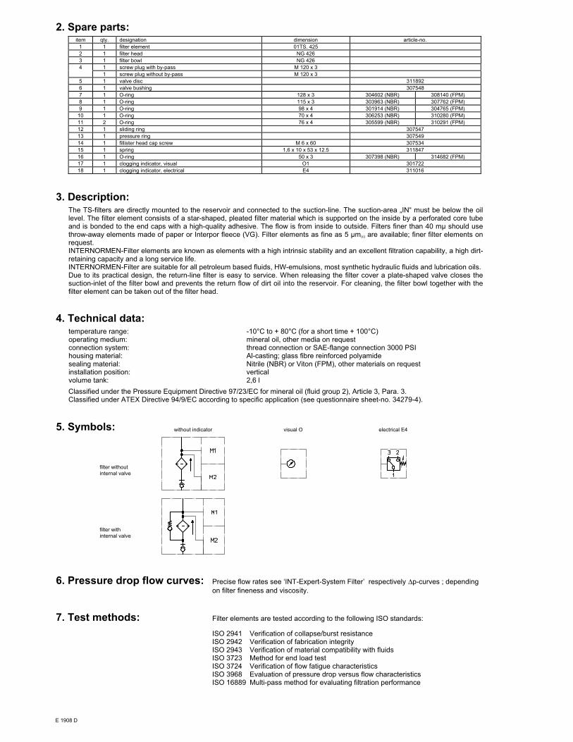
2. Spare parts:item qty. designation dimension article-no.
1 1 filter element 01TS. 425
2 1 filter head NG 426
3 1 filter bowl NG 426
4 1 screw plug with by-pass M 120 x 3
1 screw plug without by-pass M 120 x 3
5 1 valve disc 311892
6 1 valve bushing 307548
7 1 O-ring 128 x 3 304602 (NBR) 308140 (FPM)
8 1 O-ring 115 x 3 303963 (NBR) 307762 (FPM)
9 1 O-ring 98 x 4 301914 (NBR) 304765 (FPM)
10 1 O-ring 70 x 4 306253 (NBR) 310280 (FPM)
11 2 O-ring 76 x 4 305599 (NBR) 310291 (FPM)
12 1 sliding ring 307547
13 1 pressure ring 307549
14 1 fillister head cap screw M 6 x 60 307534
15 1 spring 1,6 x 10 x 53 x 12.5 311847
16 1 O-ring 50 x 3 307398 (NBR) 314682 (FPM)
17 1 clogging indicator, visual O1 301722
18 1 clogging indicator, electrical E4 311016
3. Description:The TS-filters are directly mounted to the reservoir and connected to the suction-line. The suction-area „IN“ must be below the oillevel. The filter element consists of a star-shaped, pleated filter material which is supported on the inside by a perforated core tubeand is bonded to the end caps with a high-quality adhesive. The flow is from inside to outside. Filters finer than 40 mµ should usethrow-away elements made of paper or Interpor fleece (VG). Filter elements as fine as 5 µm(c) are available; finer filter elements onrequest.INTERNORMEN-Filter elements are known as elements with a high intrinsic stability and an excellent filtration capability, a high dirt-retaining capacity and a long service life.INTERNORMEN-Filter are suitable for all petroleum based fluids, HW-emulsions, most synthetic hydraulic fluids and lubrication oils.Due to its practical design, the return-line filter is easy to service. When releasing the filter cover a plate-shaped valve closes thesuction-inlet of the filter bowl and prevents the return flow of dirt oil into the reservoir. For cleaning, the filter bowl together with thefilter element can be taken out of the filter head.
4. Technical data:temperature range: -10°C to + 80°C (for a short time + 100°C)operating medium: mineral oil, other media on requestconnection system: thread connection or SAE-flange connection 3000 PSIhousing material: Al-casting; glass fibre reinforced polyamidesealing material: Nitrile (NBR) or Viton (FPM), other materials on requestinstallation position: verticalvolume tank: 2,6 l
Classified under the Pressure Equipment Directive 97/23/EC for mineral oil (fluid group 2), Article 3, Para. 3.Classified under ATEX Directive 94/9/EC according to specific application (see questionnaire sheet-no. 34279-4).
5. Symbols: without indicator visual O electrical E4
filter without
internal valve
filter with
internal valve
6. Pressure drop flow curves: Precise flow rates see ‘INT-Expert-System Filter’ respectively ∆p-curves ; depending
on filter fineness and viscosity.
7. Test methods: Filter elements are tested according to the following ISO standards:
ISO 2941 Verification of collapse/burst resistanceISO 2942 Verification of fabrication integrityISO 2943 Verification of material compatibility with fluidsISO 3723 Method for end load testISO 3724 Verification of flow fatigue characteristicsISO 3968 Evaluation of pressure drop versus flow characteristicsISO 16889 Multi-pass method for evaluating filtration performance
E 1908 D

+49 - (0)6205 - 2094-0+49 - (0)6205 - 2094-40
phonefax
Friedensstrasse 41, 68804 Altlussheim, Germany
e-mailurl
SUCTION FILTER, for vertical tank-mounting
Series TS 625 DN 50
1. Type index:
1.1. Complete filter: (ordering example)
TS. 625. 10VG. -. B. P. -. FS. 8. -. -. O1. E41 2 3 4 5 6 7 8 9 10 11 12 13
1 series:
TS = suction filter for vertical tank-mounting
2 nominal size: 625
3 filter-material and filter-fineness:
80 G = 80 µm, 40 G = 40 µm,
25 G = 25 µm stainless steel wire mesh
25 VG = 20 µm(c), 16 VG = 15 µm(c), 10 VG = 10 µm(c),
6 VG = 7 µm(c), 3 VG = 5 µm(c) Interpor fleece (glass fibre)
25 P = 25 µm, 10 P = 10 µm paper
4 resistance of pressure difference for filter element:
- = not specified
5 filter element design:
B = both sides open
6 sealing material:
P = Nitrile (NBR)V = Viton (FPM)
7 filter element specification:
- = standardVA = stainless steel
8 connection:
FS = SAE-flange connection 3000 PSI
9 connection size:
8 = 2“
10 filter housing specification:
- = standardIS11 = see sheet-no. 40530
11 internal valve:
- = withoutS = with by-pass valve ∆p 0,28 bar
12 mesure connection at M1:
- = withoutO1 = visual, see sheet-no. 1616E4 = pressure switch, see sheet-no. 1616PA = potential equalisation
13 measure connection at M2:
possible indicators see position 12 of the type index
1.2. Filter element: (ordering example)
01TS. 625. 10VG. -. B. -. -1 2 3 4 5 6 7
1 series:
01TS. = suction filter element according to INTERNORMENfactory specification
2 nominal size: 625
3 - 5 , 7 see type index-complete filter
6 sealing material:
- = without
weight: approx. 5,5 kg
Changes of measures and design are subject to alteration!
Sheet No.
1910 C
1) The by-pass valve is integrated in the screw plug.
For the filter without a bypss-valve the opening
function is raised up to ∆p > 1 bar.
2) Connection for the potential equalisation, only for
application in the explosive area.
EDV 08/07
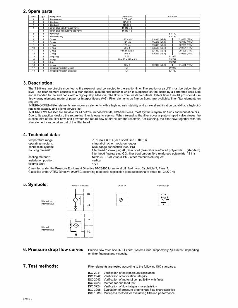
2. Spare parts:item qty. designation dimension article-no.
1 1 filter element 01TS. 625
2 1 filter head NG 625
3 1 filter bowl NG 625
4 1 screw plug with by-pass valve M 140 x 3
1 screw plug without by-pass valve M 140 x 3
5 1 valve disc 318740
6 1 valve bushing 318739
7 1 O-ring 135 x 3,5 318386 (NBR) 318387 (FPM)
8 1 O-ring 140 x 3 304604 (NBR) 307514 (FPM)
9 1 O-ring 120 x 4 305300 (NBR) 307991 (FPM)
10 1 O-ring 76 x 4 305599 (NBR) 310291 (FPM)
11 1 O-ring 104,37 x 3,53 304339 (NBR) 304390 (FPM)
12 1 O-ring 70 x 4 306253 (NBR) 310280 (FPM)
13 1 snap ring B 55 311976
14 1 spring 5,0 x 70 x 117 x 3,5 318742
15 1 disc 318741
16 1 O-ring 56 x 3 307398 (NBR) 314682 (FPM)
17 1 clogging indicator, visual E4 311016
18 1 clogging indicator, electrical O1 301722
3. Description:The TS-filters are directly mounted to the reservoir and connected to the suction-line. The suction-area „IN“ must be below the oillevel. The filter element consists of a star-shaped, pleated filter material which is supported on the inside by a perforated core tubeand is bonded to the end caps with a high-quality adhesive. The flow is from inside to outside. Filters finer than 40 µm should usethrow-away elements made of paper or Interpor fleece (VG). Filter elements as fine as 5µm(c) are available; finer filter elements onrequest.INTERNORMEN-Filter elements are known as elements with a high intrinsic stability and an excellent filtration capability, a high dirt-retaining capacity and a long service life.INTERNORMEN-Filter are suitable for all petroleum based fluids, HW-emulsions, most synthetic hydraulic fluids and lubrication oils.Due to its practical design, the return-line filter is easy to service. When releasing the filter cover a plate-shaped valve closes thesuction-inlet of the filter bowl and prevents the return flow of dirt oil into the reservoir. For cleaning, the filter bowl together with thefilter element can be taken out of the filter head.
4. Technical data:temperature range: -10°C to + 80°C (for a short time + 100°C)operating medium: mineral oil, other media on requestconnection system: SAE-flange connection 3000 PSIhousing material: filter head / screw plug AL, filter bowl glass fibre reinforced polyamide (standard)
filter head / screw plug GG, filter bowl carbon fibre reinforced polyamide (IS11)sealing material: Nitrile (NBR) or Viton (FPM), other materials on requestinstallation position: verticalvolume tank: 4,0 l
Classified under the Pressure Equipment Directive 97/23/EC for mineral oil (fluid group 2), Article 3, Para. 3.Classified under ATEX Directive 94/9/EC according to specific application (see questionnaire sheet-no. 34279-4).
5. Symbols: without indicator visual O electrical E4
filter without
internal valve
filter with
internal valve
6. Pressure drop flow curves: Precise flow rates see ‘INT-Expert-System Filter’ respectively ∆p-curves ; depending
on filter fineness and viscosity.
7. Test methods: Filter elements are tested according to the following ISO standards:
ISO 2941 Verification of collapse/burst resistanceISO 2942 Verification of fabrication integrityISO 2943 Verification of material compatibility with fluidsISO 3723 Method for end load testISO 3724 Verification of flow fatigue characteristicsISO 3968 Evaluation of pressure drop versus flow characteristicsISO 16889 Multi-pass method for evaluating filtration performance
E 1910 C
1.2. Filter element: (ordering example)
01TS. 210. 10VG. -. B. -. -1 2 3 4 5 6 7
1 series:
01TS. = suction filter element according toINTERNORMEN factory specification
2 nominal size: 210, 310
3 - 5 , 7 see type index-complete filter
6 sealing material:
- = without
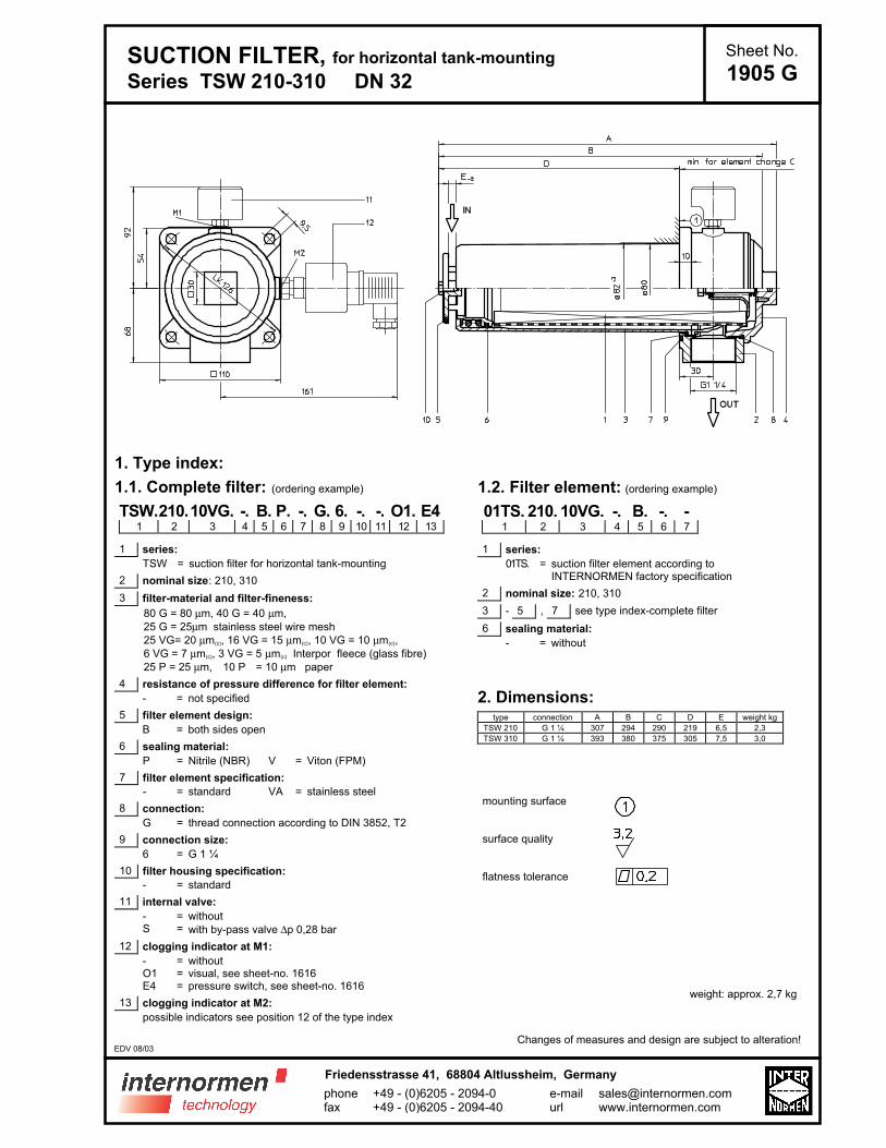
2. Dimensions:type connection A B C D E weight kg
TSW 210 G 1 ¼ 307 294 290 219 6,5 2,3
TSW 310 G 1 ¼ 393 380 375 305 7,5 3,0
mounting surface
surface quality
flatness tolerance
weight: approx. 2,7 kg
Changes of measures and design are subject to alteration!
SUCTION FILTER, for horizontal tank-mounting
Series TSW 210-310 DN 32
1. Type index:
1.1. Complete filter: (ordering example)
TSW.210.10VG. -. B. P. -. G. 6. -. -. O1. E41 2 3 4 5 6 7 8 9 10 11 12 13
1 series:
TSW = suction filter for horizontal tank-mounting
2 nominal size: 210, 310
3 filter-material and filter-fineness:
80 G = 80 µm, 40 G = 40 µm,
25 G = 25µm stainless steel wire mesh
25 VG= 20 µm(c), 16 VG = 15 µm(c), 10 VG = 10 µm(c),
6 VG = 7 µm(c), 3 VG = 5 µm(c) Interpor fleece (glass fibre)
25 P = 25 µm, 10 P = 10 µm paper
4 resistance of pressure difference for filter element:
- = not specified
5 filter element design:
B = both sides open
6 sealing material:
P = Nitrile (NBR) V = Viton (FPM)
7 filter element specification:
- = standard VA = stainless steel
8 connection:
G = thread connection according to DIN 3852, T2
9 connection size:
6 = G 1 ¼
10 filter housing specification:
- = standard
11 internal valve:
- = withoutS = with by-pass valve ∆p 0,28 bar
12 clogging indicator at M1:
- = withoutO1 = visual, see sheet-no. 1616E4 = pressure switch, see sheet-no. 1616
13 clogging indicator at M2:
possible indicators see position 12 of the type index
Sheet No.
1905 G
EDV 08/03
+49 - (0)6205 - 2094-0+49 - (0)6205 - 2094-40
phonefax
Friedensstrasse 41, 68804 Altlussheim, Germany
e-mailurl

3. Spare parts:item qty. designation dimension article-no.
TSW 210 TSW 310
1 1 filter element 01TS. 210 01TS. 310
2 1 filter head 304423
3 1 filter bowl 304518.1
4 1 filter cover M 90 x 2
5 1 O-ring 53 x 4 309143 (NBR) - (FPM)
6 1 O-ring 62 x 4 308045 (NBR) 311472 (FPM)
7 1 O-ring 75 x 3 302215 (NBR) 304729 (FPM)
8 1 O-ring 82 x 3 305191 (NBR) 305298 (FPM)
9 1 O-ring 88 x 3 304417 (NBR) 310266 (FPM)
10 1 sheet metal screw B 6,3 x 13 316641
11 1 clogging indicator, visual O1 301722
12 1 pressure switch, electrical E4 311016
4. Description:The TSW-filters are directly mounted to the reservoir and connected to the suction-line. The filter element consists of a star-shaped,pleated filter material which is supported on the inside by a perforated core tube and is bonded to the end caps with a high-qualityadhesive. The flow is from inside to outside. Filters finer than 40 mµ should use throw-away elements made of paper or Interporfleece (VG). Filter elements as fine as 5 µm (c) are available; finer filter elements on request.INTERNORMEN-Filter elements are known as elements with a high intrinsic stability and an excellent filtration capability, a high dirt-retaining capacity and a long service life.INTERNORMEN-Filter are suitable for all petroleum based fluids, HW-emulsions, most synthetic hydraulic fluids and lubrication oils.Due to its practical design, the return-line filter is easy to service. When releasing the filter cover a plate-shaped valve closes thesuction-inlet of the filter bowl and prevents leakage of fluid out of the tank. Filter element can removed from filter pot for cleaningpurposes.
5. Technical data:temperature range: -10°C to + 80°C (for a short time + 100°C)operating medium: mineral oil, other media on requestconnection system: thread connection acording to DIN 3852, T2housing material: Al-casting; glass fibre reinforced polyamidesealing material: Nitrile (NBR) or Viton (FPM), other materials on requestinstallation position: horizontalvolume tank TSW 210:
TSW 310:1,1 l1,5 l
Classified under the Pressure Equipment Directive 97/23/EC for mineral oil (fluid group 2), Article 3, Para. 3.Classified under ATEX Directive 94/9/EC according to specific application (see questionnaire sheet-no. 34279-4).
6. Symbols: without indicator visual O electrical E4
filter without
internal valve
filter with
internal valve
7. Pressure drop flow curves: Precise flow rates see ‘INT-Expert-System Filter’ respectively ∆p-curves ; depending
on filter fineness and viscosity.
8. Test methods: Filter elements are tested according to the following ISO standards:
ISO 2941 Verification of collapse/burst resistanceISO 2942 Verification of fabrication integrityISO 2943 Verification of material compatibility with fluidsISO 3723 Method for end load testISO 3724 Verification of flow fatigue characteristicsISO 3968 Evaluation of pressure drop versus flow characteristicsISO 16889 Multi-pass method for evaluating filtration performance
E 1905 G
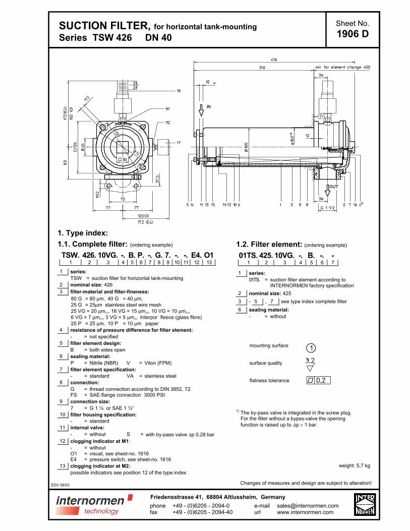
SUCTION FILTER, for horizontal tank-mounting
Series TSW 426 DN 40
Sheet No.
1906 D
1. Type index:
1.1. Complete filter: (ordering example)
TSW. 426. 10VG. -. B. P. -. G. 7. -. -. E4. O11 2 3 4 5 6 7 8 9 10 11 12 13
1 series:
TSW = suction filter for horizontal tank-mounting
2 nominal size: 426
3 filter-material and filter-fineness:
80 G = 80 µm, 40 G = 40 µm,
25 G = 25µm stainless steel wire mesh
25 VG = 20 µm(c), 16 VG = 15 µm(c), 10 VG = 10 µm(c),
6 VG = 7 µm(c), 3 VG = 5 µm(c) Interpor fleece (glass fibre)
25 P = 25 µm, 10 P = 10 µm paper
4 resistance of pressure difference for filter element:
- = not specified
5 filter element design:
B = both sides open
6 sealing material:
P = Nitrile (NBR) V = Viton (FPM)
7 filter element specification:
- = standard VA = stainless steel
8 connection:
G = thread connection according to DIN 3852, T2FS = SAE-flange connection 3000 PSI
9 connection size:
7 = G 1 ½ or SAE 1 ½“
10 filter housing specification:
- = standard
11 internal valve:
- = without S = with by-pass valve ∆p 0,28 bar
12 clogging indicator at M1:
- = withoutO1 = visual, see sheet-no. 1616E4 = pressure switch, see sheet-no. 1616
13 clogging indicator at M2:
possible indicators see position 12 of the type index
1.2. Filter element: (ordering example)
01TS. 425. 10VG. -. B. -. -1 2 3 4 5 6 7
1 series:
01TS. = suction filter element according toINTERNORMEN factory specification
2 nominal size: 425
3 - 5 , 7 see type index complete filter
6 sealing material:
- = without
mounting surface
surface quality
flatness tolerance
1) The by-pass valve is integrated in the screw plug.For the filter without a bypss-valve the opening
function is raised up to ∆p > 1 bar.
weight: 5,7 kg
Changes of measures and design are subject to alteration!EDV 08/03
+49 - (0)6205 - 2094-0+49 - (0)6205 - 2094-40
phonefax
Friedensstrasse 41, 68804 Altlussheim, Germany
e-mailurl
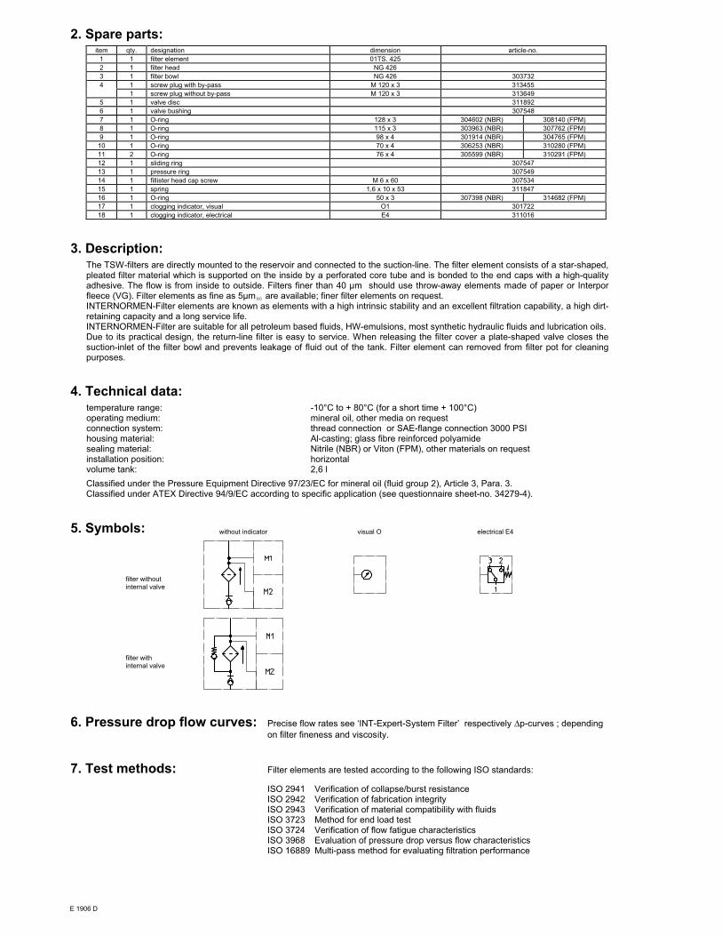
2. Spare parts:item qty. designation dimension article-no.
1 1 filter element 01TS. 425
2 1 filter head NG 426
3 1 filter bowl NG 426 303732
4 1 screw plug with by-pass M 120 x 3 313455
1 screw plug without by-pass M 120 x 3 313649
5 1 valve disc 311892
6 1 valve bushing 307548
7 1 O-ring 128 x 3 304602 (NBR) 308140 (FPM)
8 1 O-ring 115 x 3 303963 (NBR) 307762 (FPM)
9 1 O-ring 98 x 4 301914 (NBR) 304765 (FPM)
10 1 O-ring 70 x 4 306253 (NBR) 310280 (FPM)
11 2 O-ring 76 x 4 305599 (NBR) 310291 (FPM)
12 1 sliding ring 307547
13 1 pressure ring 307549
14 1 fillister head cap screw M 6 x 60 307534
15 1 spring 1,6 x 10 x 53 311847
16 1 O-ring 50 x 3 307398 (NBR) 314682 (FPM)
17 1 clogging indicator, visual O1 301722
18 1 clogging indicator, electrical E4 311016
3. Description:The TSW-filters are directly mounted to the reservoir and connected to the suction-line. The filter element consists of a star-shaped,pleated filter material which is supported on the inside by a perforated core tube and is bonded to the end caps with a high-qualityadhesive. The flow is from inside to outside. Filters finer than 40 µm should use throw-away elements made of paper or Interporfleece (VG). Filter elements as fine as 5µm (c) are available; finer filter elements on request.INTERNORMEN-Filter elements are known as elements with a high intrinsic stability and an excellent filtration capability, a high dirt-retaining capacity and a long service life.INTERNORMEN-Filter are suitable for all petroleum based fluids, HW-emulsions, most synthetic hydraulic fluids and lubrication oils.Due to its practical design, the return-line filter is easy to service. When releasing the filter cover a plate-shaped valve closes thesuction-inlet of the filter bowl and prevents leakage of fluid out of the tank. Filter element can removed from filter pot for cleaningpurposes.
4. Technical data:temperature range: -10°C to + 80°C (for a short time + 100°C)operating medium: mineral oil, other media on requestconnection system: thread connection or SAE-flange connection 3000 PSIhousing material: Al-casting; glass fibre reinforced polyamidesealing material: Nitrile (NBR) or Viton (FPM), other materials on requestinstallation position: horizontalvolume tank: 2,6 l
Classified under the Pressure Equipment Directive 97/23/EC for mineral oil (fluid group 2), Article 3, Para. 3.Classified under ATEX Directive 94/9/EC according to specific application (see questionnaire sheet-no. 34279-4).
5. Symbols: without indicator visual O electrical E4
filter without
internal valve
filter with
internal valve
6. Pressure drop flow curves: Precise flow rates see ‘INT-Expert-System Filter’ respectively ∆p-curves ; depending
on filter fineness and viscosity.
7. Test methods: Filter elements are tested according to the following ISO standards:
ISO 2941 Verification of collapse/burst resistanceISO 2942 Verification of fabrication integrityISO 2943 Verification of material compatibility with fluidsISO 3723 Method for end load testISO 3724 Verification of flow fatigue characteristicsISO 3968 Evaluation of pressure drop versus flow characteristicsISO 16889 Multi-pass method for evaluating filtration performance
E 1906 D

SUCTION FILTER, for horizontal tank-mounting
Series TSW 625 DN 50
Sheet No.
1911 C
1. Type index:
1.1. Complete filter: (ordering example)
TSW. 625. 10VG. -. B. P. -. FS. 8. -. -. O1. E41 2 3 4 5 6 7 8 9 10 11 12 13
1 series:
TSW = suction filter for horizontal tank-mounting
2 nominal size: 625
3 filter-material and filter-fineness:
80 G = 80 µm, 40 G = 40 µm,
25 G = 25µm stainless steel wire mesh
25 VG = 20 µm(c), 16 VG = 15 µm(c), 10 VG = 10 µm(c),
6 VG = 7 µm(c), 3 VG = 5 µm(c) Interpor fleece (glass fibre)
25 P = 25 µm, 10 P = 10 µm paper
4 resistance of pressure difference for filter element:
- = not specified
5 filter element design:
B = both sides open
6 sealing material:
P = Nitrile (NBR)V = Viton (FPM)
7 filter element specification:
- = standardVA = stainless steel
8 connection:
FS = SAE-flange connection 3000 PSI
9 connection size:
8 = 2“
10 filter housing specification:
- = standardIS11 = see sheet-no. 40530
11 internal valve:
- = withoutS = with by-pass valve ∆p 0,28 bar
12 measure connection at M1:
- = withoutO1 = visual, see sheet-no. 1616E4 = pressure switch, see sheet-no. 1616PA = potential equalisation
13 measure connection at M2:
possible indicators see position 12 of the type index
1.2. Filter element: (ordering example)
01TS. 625. 10VG. -. B. -. -1 2 3 4 5 6 7
1 series:
01TS. = suction filter element according toINTERNORMEN factory specification
2 nominal size: 625
3 - 5 , 7 see type index complete filter
6 sealing material:
- = without
mounting surface
surface quality
flatness tolerance
1) The by-pass valve is integrated in the screw plug.
For the filter without a bypss-valve the opening
function is raised up to ∆p > 1 bar.
2) Connection for the potential equalisation, only for
application in the explosive area.
weight: approx. 5,5 kg
Changes of measures and design are subject to alteration!
EDV 08/07
+49 - (0)6205 - 2094-0+49 - (0)6205 - 2094-40
phonefax
Friedensstrasse 41, 68804 Altlussheim, Germany
e-mailurl

2. Spare parts:item qty. designation dimension article-no.
1 1 filter element 01TS. 625
2 1 filter head NG 625
3 1 filter bowl NG 625
4 1 screw plug with by-pass valve M 140 x 3
1 screw plug without by-pass valve M 140 x 3
5 1 valve disc 318740
6 1 valve bushing 318739
7 1 O-ring 135 x 3,5 318386 (NBR) 318387 (FPM)
8 1 O-ring 140 x 3 304604 (NBR) 307514 (FPM)
9 1 O-ring 120 x 4 305300 (NBR) 307991 (FPM)
10 1 O-ring 76 x 4 305599 (NBR) 310291 (FPM)
11 1 O-ring 104,37 x 3,53 304339 (NBR) 304390 (FPM)
12 1 O-ring 70 x 4 306253 (NBR) 310280 (FPM)
13 1 snap ring B 55 311976
14 1 spring 5,0 x 70 x 117 x 3,5 318742
15 1 disc 318741
16 1 O-ring 56 x 3 307398 (NBR) 314682 (FPM)
17 1 clogging indicator, visual E4 311016
18 1 clogging indicator, electrical O1 301722
3. Description:The TSW-filters are directly mounted to the reservoir and connected to the suction-line. The filter element consists of a star-shaped,pleated filter material which is supported on the inside by a perforated core tube and is bonded to the end caps with a high-qualityadhesive. The flow is from inside to outside. Filters finer than 40 mµ should use throw-away elements made of paper or Interporfleece (VG). Filter elements as fine as 5 µm (c) are available; finer filter elements on request.INTERNORMEN-Filter elements are known as elements with a high intrinsic stability and an excellent filtration capability, a high dirt-retaining capacity and a long service life.INTERNORMEN-Filter are suitable for all petroleum based fluids, HW-emulsions, most synthetic hydraulic fluids and lubrication oils.Due to its practical design, the return-line filter is easy to service. When releasing the filter cover a plate-shaped valve closes thesuction-inlet of the filter bowl and prevents leakage of fluid out of the tank. Filter element can removed from filter pot for cleaningpurposes.
4. Technical data:temperature range: -10°C to + 80°C (for a short time + 100°C)operating medium: mineral oil, other media on requestconnection system: SAE-flange connection 3000 PSIhousing material: filter head / screw plug AL, filter bowl glass fibre reinforced polyamide (standard)
filter head / screw plug GG, filter bowl carbon fibre reinforced polyamide (IS11)sealing material: Nitrile (NBR) or Viton (FPM), other materials on requestinstallation position: horizontalvolume tank: 4,0 l
Classified under the Pressure Equipment Directive 97/23/EC for mineral oil (fluid group 2), Article 3, Para. 3.Classified under ATEX Directive 94/9/EC according to specific application (see questionnaire sheet-no. 34279-4).
5. Symbols: without indicator visual O electrical E4
filter without
internal valve
filter with
internal valve
6. Pressure drop flow curves: Precise flow rates see ‘INT-Expert-System Filter’ respectively ∆p-curves ; depending
on filter fineness and viscosity.
7. Test methods: Filter elements are tested according to the following ISO standards:
ISO 2941 Verification of collapse/burst resistanceISO 2942 Verification of fabrication integrityISO 2943 Verification of material compatibility with fluidsISO 3723 Method for end load testISO 3724 Verification of flow fatigue characteristicsISO 3968 Evaluation of pressure drop versus flow characteristicsISO 16889 Multi-pass method for evaluating filtration performance
E 1911 C