such as the vertical stabilizer and wing tips. The ... · Magnetic Variation and Compass Errors ......
4
3-3 Figure 3-2. Magnetic compass. N 33 30 27 N-S E-W Float Filler hole and plug Outer case Compensating magnet Instrument lamp Expansion unit Lubber line Compass card Lens Sensing magnet Compensating screws Pivot assembly Fluid chamber Figure 3-3. Effects of variation. Zero variation N 33 30 W 24 21 S 15 12 E 6 3 N 33 30 W 24 21 S 15 12 E 6 3 N 33 30 W 24 21 S 15 12 E 6 3 NP MP SP SP NP MP NP MP SP East variation West variation such as the vertical stabilizer and wing tips. The direction is then transmitted electrically to repeater indicators on the instrument panels. Direct-Indicating Magnetic Compass Basically, the magnetic compass is a magnetized rod pivoted at its middle, with several features incorporated to improve its performance. One type of direct-indicating magnetic compass, the B-16 compass (often called the whiskey compass), is illustrated in Figure 3-2. It is used as a standby compass in case of failure of the electrical system that operates the remote compasses. It is a reliable compass and gives good navigational results if used carefully. Magnetic Variation and Compass Errors The earth’s magnetic poles are joined by irregular curves called magnetic meridians. The angle between the magnetic meridian and the geographic meridian is called the magnetic variation. Variation is listed on charts as east or west. When variation is east, magnetic north (MN) is east of true north (TN). Similarly, when variation is west, MN is west of TN. [Figure 3-3] Lines connecting points having the same magnetic variation are called isogonic lines. [Figure 3-4] Compensate for magnetic variation to convert a compass direction to true direction. Compass error is caused by nearby magnetic influences, such as magnetic material in the structure of the aircraft and its electrical systems. These magnetic forces deflect a compass needle from its normal alignment. The amount of such deflection is called deviation which, like variation, is labeled “east” or “west” as the north-seeking end of the compass is deflected east or west of MN, respectively.
Transcript of such as the vertical stabilizer and wing tips. The ... · Magnetic Variation and Compass Errors ......

3-3
Figure 3-2. Magnetic compass.
N 33 30 27
N-S E-W
Float Filler hole and plug
Outer case
Compensating magnet
Instrument lamp
Expansion unit
Lubber line
Compass card
Lens
Sensing magnet
Compensating screws
Pivot assembly
Fluidchamber
Figure 3-3. Effects of variation.
Zerovariation
N 33
30
W
24
21 S 15
12
E
6
3 N
33
30
W
24
21 S 15
12
E
6
3 N
33
30
W
24
21 S 15
12
E
6
3
NP
MP
SP SP
NP
MP
NP
MP
SP
Eastvariation
Westvariation
such as the vertical stabilizer and wing tips. The direction is then transmitted electrically to repeater indicators on the instrument panels.
Direct-Indicating Magnetic CompassBasically, the magnetic compass is a magnetized rod pivoted at its middle, with several features incorporated to improve its performance. One type of direct-indicating magnetic compass, the B-16 compass (often called the whiskey compass), is illustrated in Figure 3-2. It is used as a standby compass in case of failure of the electrical system that operates the remote compasses. It is a reliable compass and gives good navigational results if used carefully.
Magnetic Variation and Compass Errors
The earth’s magnetic poles are joined by irregular curves called magnetic meridians. The angle between the magnetic
meridian and the geographic meridian is called the magnetic variation. Variation is listed on charts as east or west. When variation is east, magnetic north (MN) is east of true north (TN). Similarly, when variation is west, MN is west of TN. [Figure 3-3] Lines connecting points having the same magnetic variation are called isogonic lines. [Figure 3-4] Compensate for magnetic variation to convert a compass direction to true direction.
Compass error is caused by nearby magnetic influences, such as magnetic material in the structure of the aircraft and its electrical systems. These magnetic forces deflect a compass needle from its normal alignment. The amount of such deflection is called deviation which, like variation, is labeled “east” or “west” as the north-seeking end of the compass is deflected east or west of MN, respectively.

3-4
Figure 3-4. Isogonic lines show same magnetic variation.
0˚
15˚N
30˚N
45˚N
60˚N
75˚N
15˚S
30˚S
45˚S
0˚
15˚N
30˚N
45˚N
60˚N
75˚N
15˚S
30˚S
45˚S
0˚15˚W30˚W45˚W60˚W90˚W 75˚W105˚W120˚W135˚W150˚W165˚W 15˚E 30˚E 45˚E 60˚E 75˚E105˚E 120˚E 135˚E 150˚E 165˚E 180˚
0˚15˚W30˚W45˚W60˚W90˚W 75˚W105˚W120˚W135˚W150˚W165˚W 15˚E 30˚E 45˚E 60˚E 75˚E105˚E 120˚E 135˚E 150˚E 165˚E 180˚60˚ 80˚ 100˚ 120˚ 140˚ 160˚ 180˚ 160˚ 140˚ 120˚ 100˚ 80˚ 60˚ 40˚ 20˚ 0˚ 20˚ 40˚ 60˚ 80˚ 100˚
80˚ 100˚ 120˚ 140˚ 160˚ 180˚ 160˚ 140˚ 120˚ 100˚ 80˚ 60˚ 40˚ 20˚ 0˚ 20˚ 40˚ 60˚ 80˚ 100˚69
˚ 60
˚
40˚
2
0˚
0˚
20˚
40˚
60
˚
7
8˚
69˚
60
˚
40˚
2
0˚
0˚
20˚
40˚
60
˚
7
8˚
30˚E20
˚E10
˚E
NO VARIA
TION 10˚W
10˚W
30˚W40˚W50˚W
70˚W
20˚W
20˚E
30˚E
40˚E50˚E
60˚E
10˚E
10˚E
20˚E
30˚E
40˚E
50˚E
30˚E
20˚E10˚E
30˚W
40˚W
50˚W60
˚W70˚W
20˚W
10˚W
30˚E
20˚E
10˚E
10˚W
20˚W
30˚W
40˚W
50˚W
60˚W
70˚W
80˚W
20˚W
10˚W
NO VARIATION
NO
VARIATIO
N
NO VARIATIO
N
Figure 3-5. Find true heading by working backwards.
True north
Compass north
Magnetic north
Compass heading
Magnetic heading
True heading
Var
iatio
n 10
°ED
evia
tion
3°E
TH
TO FIND COMPASS HEADING
VAR MH DEV CH
138 −10 ? −3 ?
138 −10 128 −3 125
TH
TO FIND TRUE HEADING
VAR MH DEV CH
? −10 ? −3 125
138 −10 128 −3 125
The correction for variation and deviation is usually expressed as a plus or minus value and is computed as a correction to true heading (TH). If variation or deviation is east, the sign of the correction is minus; if west, the sign is plus. A rule of thumb for this correction is easily remembered as east is least and west is best.
Aircraft headings are expressed as TH or magnetic headings (MH). If the heading is measured in relation to geographical north, it is a TH. If the heading is in reference to MN, it is a MH; if it is in reference to the compass lubber line, it is a compass heading (CH). CH corrected for variation and deviation is TH. MH corrected for variation is TH.
This relationship is best expressed by reference to the navigator’s log, where the various headings and corrections are listed as TH, variation (var), MH, deviation (dev), and CH. [Figure 3-5] Thus, if an aircraft is flying in an area where the variation is 10° E and the compass has a deviation of 3° E, the relationship would be expressed as follows, assuming a CH of 125°:
TH var MH dev CH138 – 10 = 128 – 3 = 125
Variation
Variation has been measured throughout the world and the values found have been plotted on charts. Isogonic lines are
3-5
Figure 3-6. Deviation changes with heading.
0 10 20 30 40 50 60 70 80 90 100 110 120 130 140 150 160 170 180 190 200 210 220
230
240
250
260
27
0 2
80
290
300
31
0 32
0 330 340 350
Totaldeviationeffects
Magnetic North
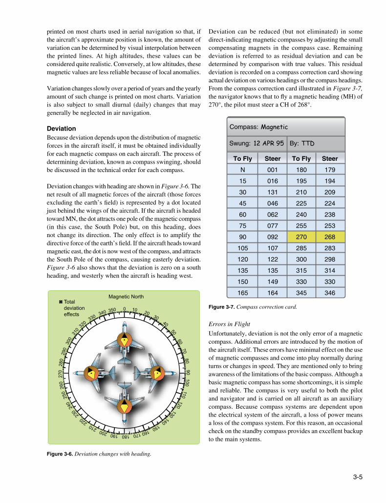
Figure 3-7. Compass correction card.
Swung:
Compass:
By:12 APR 95
Magnetic
TTD
To Fly
N
15
30
45
60
75
90
105
120
135
150
165
Steer
001
016
131
046
062
077
092
107
122
135
149
164
Steer
179
194
209
224
238
253
268
283
298
314
330
346
To Fly
180
195
210
225
240
255
270
285
300
315
330
345
printed on most charts used in aerial navigation so that, if the aircraft’s approximate position is known, the amount of variation can be determined by visual interpolation between the printed lines. At high altitudes, these values can be considered quite realistic. Conversely, at low altitudes, these magnetic values are less reliable because of local anomalies.
Variation changes slowly over a period of years and the yearly amount of such change is printed on most charts. Variation is also subject to small diurnal (daily) changes that may generally be neglected in air navigation.
DeviationBecause deviation depends upon the distribution of magnetic forces in the aircraft itself, it must be obtained individually for each magnetic compass on each aircraft. The process of determining deviation, known as compass swinging, should be discussed in the technical order for each compass.
Deviation changes with heading are shown in Figure 3-6. The net result of all magnetic forces of the aircraft (those forces excluding the earth’s field) is represented by a dot located just behind the wings of the aircraft. If the aircraft is headed toward MN, the dot attracts one pole of the magnetic compass (in this case, the South Pole) but, on this heading, does not change its direction. The only effect is to amplify the directive force of the earth’s field. If the aircraft heads toward magnetic east, the dot is now west of the compass, and attracts the South Pole of the compass, causing easterly deviation. Figure 3-6 also shows that the deviation is zero on a south heading, and westerly when the aircraft is heading west.
Deviation can be reduced (but not eliminated) in some direct-indicating magnetic compasses by adjusting the small compensating magnets in the compass case. Remaining deviation is referred to as residual deviation and can be determined by comparison with true values. This residual deviation is recorded on a compass correction card showing actual deviation on various headings or the compass headings. From the compass correction card illustrated in Figure 3-7, the navigator knows that to fly a magnetic heading (MH) of 270°, the pilot must steer a CH of 268°.
Errors in Flight
Unfortunately, deviation is not the only error of a magnetic compass. Additional errors are introduced by the motion of the aircraft itself. These errors have minimal effect on the use of magnetic compasses and come into play normally during turns or changes in speed. They are mentioned only to bring awareness of the limitations of the basic compass. Although a basic magnetic compass has some shortcomings, it is simple and reliable. The compass is very useful to both the pilot and navigator and is carried on all aircraft as an auxiliary compass. Because compass systems are dependent upon the electrical system of the aircraft, a loss of power means a loss of the compass system. For this reason, an occasional check on the standby compass provides an excellent backup to the main systems.

3-6
Figure 3-8. N-1 compass system components.
33
3024
2I I5
I26
3
33
3024
2I I5
I26
3
33
3024
2I I5I2
6
30
ALTITUDE30 30
60
OFF
6090 90
R L
1
2
AMPLIFIER
Directional gyro
Amplifier
Remote compasstransmitter
Gyro-magneticcompass indicator N-1 master
indicator
Annunciatorpointer
Headingpointer
Latitudecorrection control
knob
Latitudecorrection
scaleLatitude
correctionpointer
Correctionservo
indicator
Synchronizercontrol knob
Other equipmentAutomatic
pilotSlavingcontrol
Powerinput
Gyro magneticcompass indicator
3
45
4
4
Remote-Indicating Gyro-Stabilized Magnetic Compass SystemA chief disadvantage of the simple magnetic compass is its susceptibility to deviation. In remote-indicating gyro-stabilized compass systems, this difficulty is overcome by locating the compass direction-sensing device outside magnetic fields created by electrical circuits in the aircraft. This is done by installing the direction-sensing device in a remote part of the aircraft, such as the outer extremity of a wing or vertical stabilizer. Indicators of the compass system can then be located throughout the aircraft without regard to magnetic disturbances.
Several kinds of compass system are used in aircraft systems. All include the following five basic components: remote compass transmitter, directional gyro (DG), amplifier, heading indicators, and slaving control. Though the names of these components vary among systems, the principle of operation is identical for each. Thus, the N-1 compass system shown in Figure 3-8 can be considered typical of all such systems.
The N-1 compass system is designed for airborne use at all latitudes. It can be used either as a magnetic-slaved compass or as a DG. In addition, the N-1 generates an electric signal that is used as an azimuth reference by the autopilot, the radar system, the navigation and bombing computers, and various compass cards.
Remote Compass TransmitterThe remote compass transmitter is the magnetic-direction sensing component of the compass system when the system is in operation as a magnetic-slaved compass. The transmitter is located as far from magnetic disturbances of the aircraft as
possible, usually in a wing tip or the vertical stabilizer. The transmitter senses the horizontal component of the earth’s magnetic field and electrically transmits it to the master indicator. The compensator, an auxiliary unit of the remote compass transmitter, is used to eliminate most of the magnetic deviation caused by the aircraft electrical equipment and ferrous metal when a deviation-free location for the remote compass transmitter is not available.
Directional Gyro (DG)The DG is the stabilizing component of the compass system when the system is in magnetic-slaved operation. When the compass system is in DG operation, the gyro acts as the directional reference component of the system.
AmplifierThe amplifier is the receiving and distributing center of the compass system. Azimuth correction and leveling signals originating in the components of the system are each received, amplified, and transmitted by separate channels in the amplifier. Primary power to operate the compass is fed to the amplifier and distributed to the systems components.
Master IndicatorThe master indicator is the heading-indicating component of the compass system. The mechanism in the master indicator integrates all data received from the directional gyro and the remote compass transmitter, corrects the master indicator heading pointer for azimuth drift of the DG due to the earth’s rotation, and provides takeoff signals for operating remote indicators, radar, navigation computers, and directional control of the autopilot.