Subthreshold Logic Energy Minimization with Application-Driven Performance
25
Subthreshold Logic Energy Minimization with Application-Driven Performance EE241 Final Project Will Biederman Dan Yeager
-
Upload
lorenzo-romero -
Category
Documents
-
view
44 -
download
1
description
Subthreshold Logic Energy Minimization with Application-Driven Performance. EE241 Final Project Will Biederman Dan Yeager. Outline. Motivation and Introduction Problem Analysis Prior Work Proposed Solution Design Procedure Minimum Energy Tracking Loop Results. Motivation. - PowerPoint PPT Presentation
Transcript of Subthreshold Logic Energy Minimization with Application-Driven Performance
Subthreshold Logic Energy Minimization with Application-
Driven PerformanceEE241 Final Project
Will BiedermanDan Yeager
Outline
• Motivation and Introduction• Problem Analysis• Prior Work• Proposed Solution• Design Procedure• Minimum Energy Tracking Loop• Results

Motivation
• Emerging Markets: Wireless Sensors– Shipment tracking, biomedical electronics,
environmental monitoring
• Fixed Computation -> Minimize E/op
• 10-year life applications (100k hrs) AAA Battery– > ~ 10 uA * Vdd

Introduction: Conventional MEP
• Lowering E/op– Lower VDD! How Far?
– Minimum Energy Point may not provide sufficient performance

Problem Analysis: Fop Set by MEP
• Fop set by MEP (VDD)– Fop can change with environment conditions (T)
• MEP doesn’t track with throughput demands– Wasted power during sleep or low computation

Problem Analysis: σVth
• Variation in Vth– LER & RDF
• Economics motivate continued technology scaling– ( Moore’s Law!! )

Prior Work: Adaptive Fop
• Correlated Path Delay - Temp/Process- Critical path exceeds Tclk
• Replica circuits can be used to compensate– ABB– AVS
• These circuits cannot adapt to uncorrelated Vth variations from LER and RDF!

Prior Work: Dealing with σVth
• σVth due to LER/ RDF– Spatially Uncorrelated
• Upsizing- C increases• Pipeline Depth- α decrease)• Increase technology node
(C increase & Moore’s Law)

Proposed Solution
1. Compensate for correlated temperature and process variation with an analog VTH sensor
2. Compensate for uncorrelated delay variation with timing error detection
-> How do we optimize device sizing and pipeline depth in this regime?

Energy Optimization
• Delay is stochastic:

Energy Optimization
• Energy is also stochastic:

Energy Optimization• Its all pretty messy… how do we optimize?1. Yield– Pick a target yield -> sets conf, (# of sigma)– Allocate half of the yield to timing and half to energy– YTotal = √(YEnergy + Ytiming)
2. Design– MATLAB model to find optimal design parameters– Choose Vdd_opt, Vth_opt, n (pipeline logic depth), etc.
3. Power On– Our tracking loop ensures that all chips meet the timing
constraint, but at the expense of energy– We can quickly pass / fail chips based on the supply
voltage set by the tracking loop

Energy Tracking Loop
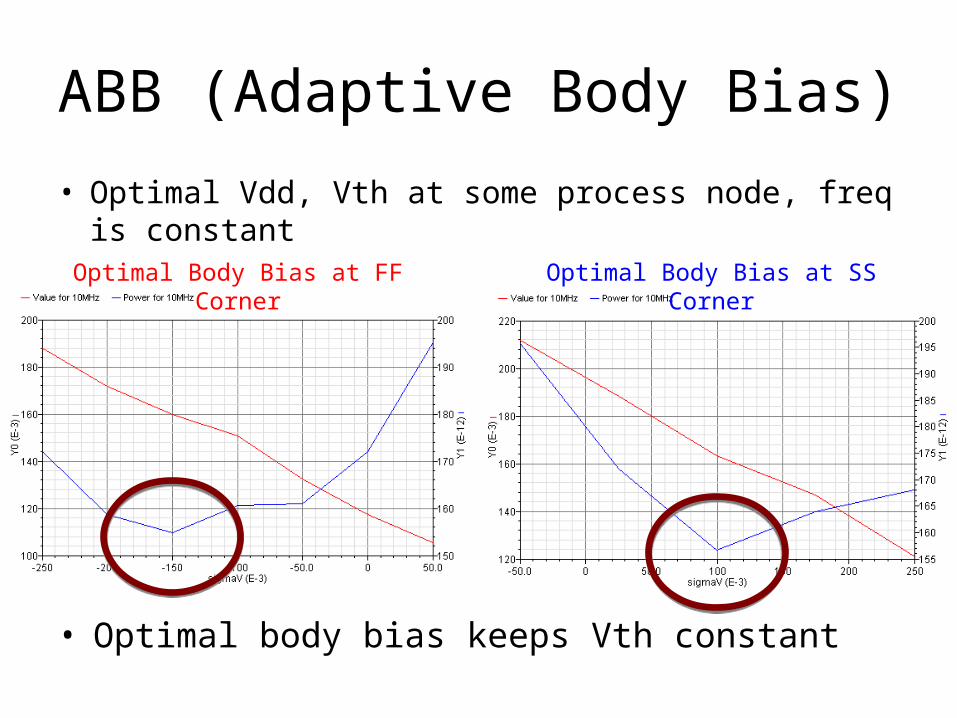
ABB (Adaptive Body Bias)
• Optimal Vdd, Vth at some process node, freq is constant
• Optimal body bias keeps Vth constant
Optimal Body Bias at FF Corner Optimal Body Bias at SS Corner
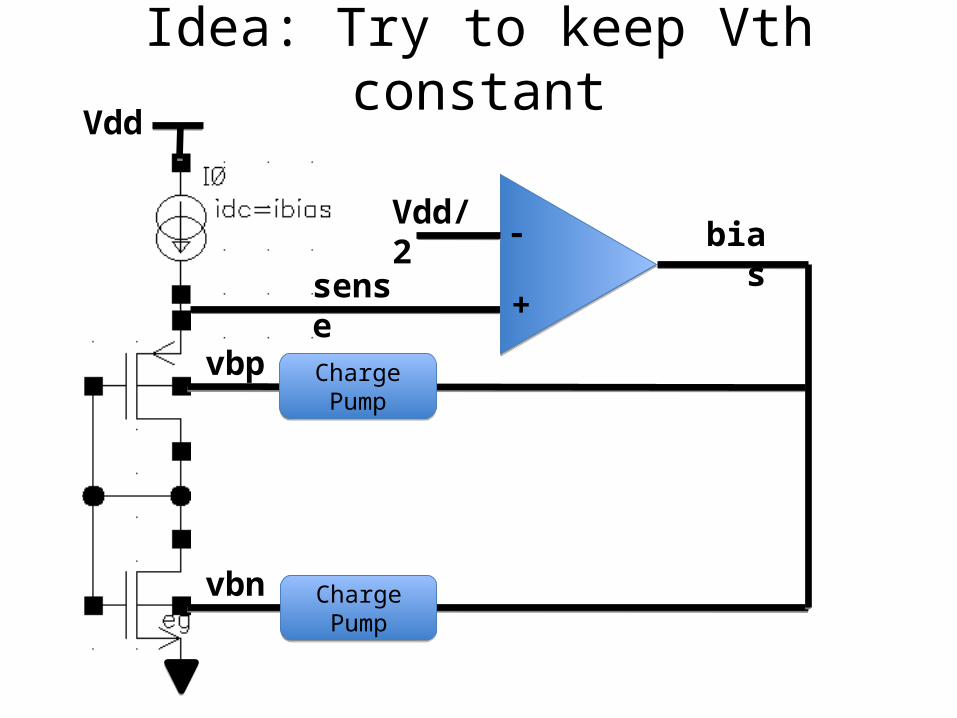
Idea: Try to keep Vth constant
vbn
vbp
sense
Vdd/2
Vdd
bias-
+
Charge PumpCharge Pump
Charge PumpCharge Pump

Body Bias Correction Works!
Process Corner
Body
Bia
s Vo
ltage
Temperature

DVS (Dynamic Voltage Scaling)

Tracking Loop Results – No ABB300mV
175mV
VDD =
VDD =
ERROR
ERROR
Pipeline In/Out Timing:
Pipeline In/Out Timing:
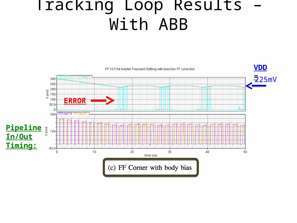
Tracking Loop Results – With ABB
225mV
VDD =
ERROR
Pipeline In/Out Timing:

Conclusion
• Maximum energy efficiency -> subthreshold operation -> serious variability problems
• Correlated (P,T) vs. uncorrelated (RDF) variations– ex situ (replica) vs. in situ (timing detection)
• ABB and DVS can effectively provide optimal region of operation

References

Backup
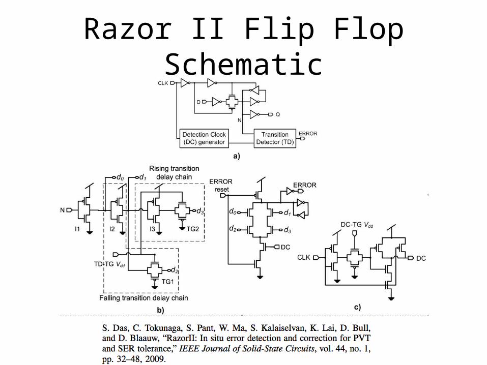
Razor II Flip Flop Schematic

Razor II Timing

Energy Optimization
• We are concerned with the longest of p critical paths: