Substructure Tutorial - AASHTOWare Bridge Design … Drilled Shaft.pdf · analysis in tutorial “3...
14
AASHTOWare BrD 6.8 Substructure Tutorial Pier Drilled Shaft Example
Transcript of Substructure Tutorial - AASHTOWare Bridge Design … Drilled Shaft.pdf · analysis in tutorial “3...

AASHTOWare BrD 6.8
Substructure Tutorial Pier Drilled Shaft Example

Pier Drilled Shaft Example
Last Modified: 9/26/2016 1
51'-0"
18'-9"
5'-3"
17'-7"
EL 76.00
EL 35.00
Physical bottom of shaft
Groundline EL 54.50
Pier 3 Elevation
Drilled Shaft Foundations
Looking Sta Ahead
3'-0"
1'-8"
6'-9"
CL Column1 CL Column2 CL Column3
18'-9" 6'-9"
5'-3"
3'-0" Dia. Column
(Typ)
25'-9"
Superstructure Definition
Reference Line
3'-3" 3'-3"9'-0" 9'-0" 9'-0" 9'-0"
51'-6"
BL SR 456
9'-0"
4'-0" Dia. Shaft
(Typ)
EL 53.75
EL 40.00
Pt of Fixity found
from outside source

Pier Drilled Shaft Example
Last Modified: 9/26/2016 2
17'-7"
EL 35.00
Physical bottom of shaft
Typical Column Reinforcement
EL 53.75
EL 40.00
Pt of Fixity
Bottom of drilled shaft in Opis
B B
A A
13'-9"
8 - #10 bars
12 - #10 bars
4'-0"
6-0" lap
#4 spiral @
3" pitch (typ.)
EL 35.00
Physical bottom of shaft
EL 53.75
#4 spiral @
3" pitch (typ.)
Typical Shear Reinforcement

Pier Drilled Shaft Example
Last Modified: 9/26/2016 3
BrD Substructure Training
Pier Drilled Shaft Example
This example modifies one of the spread footings in the BID20 example to be a drilled shaft foundation. BrD
substructure has the ability to perform a soil-structure interaction analysis. You can find an example describing the
analysis in tutorial “3 Drilled Shaft” in 2012 User Group – Training.
In the event that you do not wish to use the BrD soil-structure interaction analysis, this example describes how to
analyze a pier with drilled shafts considering a user-defined point of fixity. You can enter a point of fixity found
from an outside source, such as LPile or COM624, as the base of the drilled shaft in BrD. BrD can then perform a
finite element analysis and spec check of the pier considering that point of fixity.
Open the Bridge workspace for BID 20 as shown below:

Pier Drilled Shaft Example
Last Modified: 9/26/2016 4
The ‘3-column pier’ example is a multi-frame pier on spread footings as shown below.
We are going to model the foundation for Column 1 as a drilled shaft instead of a spread footing.

Pier Drilled Shaft Example
Last Modified: 9/26/2016 5
Open the window for Column 1 and un-check the checkboxes for the existing and current foundation as shown
below:

Pier Drilled Shaft Example
Last Modified: 9/26/2016 6
Open the Column 1 Components window and increase the number of segments to 2 as shown below:

Pier Drilled Shaft Example
Last Modified: 9/26/2016 7
Open the Geometry window for Column 1 and enter the drilled shaft point of fixity as the bottom of Segment 2
elevation. Then select the bottom schematic in the window and enter the width of the drilled shaft section as 4.0’.

Pier Drilled Shaft Example
Last Modified: 9/26/2016 8
Create a reinforcement definition for the drilled shaft segment using the Pattern Wizard as shown below. Be sure to
select the column segment 2 as shown so the reinforcement bar coordinates will be generated correctly for the 4’
wide drilled shaft segment.

Pier Drilled Shaft Example
Last Modified: 9/26/2016 9
Assign the column reinforcement as follows:
The first row describes the rebar in the drilled shaft segment. Mark these bars as “developed at start” since we can
assume that the actual length of the drilled shaft segment below the point of fixity at elevation 40.0ft provides
enough length for these bars to be fully developed.
The second row describes the lap bars extending from the column into the drilled shaft.
The third row describes the column reinforcement. Mark these bars as “developed at end” since we can assume the
bars extend far enough into the cap to be developed.

Pier Drilled Shaft Example
Last Modified: 9/26/2016 10
The shear reinforcement in the column is described as follows:
The overlap of spirals at the column-drilled shaft connection is a detailing requirement that can be ignored in our
BrD description.
Pier Drilled Shaft Example
Last Modified: 9/26/2016 11
The 3D schematic for the pier alternative appears as follows.
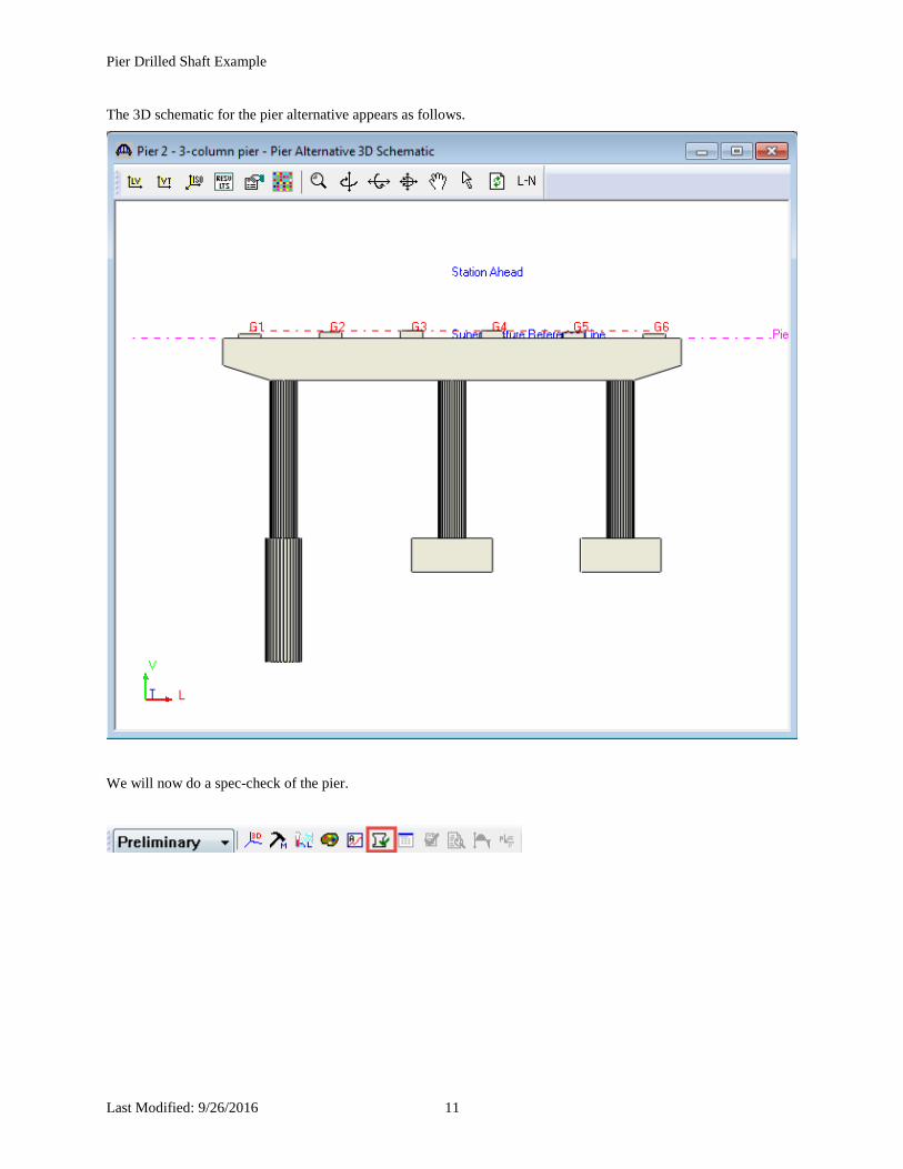
We will now do a spec-check of the pier.

Pier Drilled Shaft Example
Last Modified: 9/26/2016 12
Specification checks are performed at the following locations in Column 1:
We are primarily interested in the following 2 points:
1. The 0.00 ft location is the base of the column in BrD which is the point of fixity for the drilled shaft
segment.
2. The 13.75 ft location is the interface of the column and drilled shaft segment.
The remaining points are the locations where the reinforcement achieves full development.

Pier Drilled Shaft Example
Last Modified: 9/26/2016 13
The spec-check at the point of fixity is shown below: