
Substructure synthesis method for a nonlinear...
17
JOURNAL OF SOUND AND VIBRATION Journal of Sound and Vibration 321 (2009) 704–720 Substructure synthesis method for a nonlinear structure with a sliding mode condition Dae-Kwan Kim a , Min-Su Lee b , Jae-Hung Han c, a COMS Systems Department, Korea Aerospace Research Institute, 115 Gwahangno, Yuseong-gu, Daejeon 305-333, Republic of Korea b Mechatronics Center, Institute of Industrial Technology, Samsung Heavy Industry, 103-28 Munji-dong,Yuseong-gu, Daejoen 305-380, Republic of Korea c Department of Aerospace Engineering, KAIST, 335 Gwahangno, Yuseong-gu, Daejeon 305-701, Republic of Korea Received 20 January 2007; received in revised form 26 April 2008; accepted 27 September 2008 Handling Editor: L.G. Tham Available online 18 November 2008 Abstract The component mode synthesis (CMS) method is widely used to establish reduced dynamic models of complex structures so that iterative problems such as flutter analyses can be efficiently analyzed with reasonable cost and time. In the present study, a structural coupling method is developed for the dynamic analysis of a nonlinear structure consisting of substructures connected by nonlinear interfaces such as nonlinear hinge joints or sliding mode conditions. In order to verify the coupling method extended to consider the hinge joints, a numerical plate model consisting of two substructures and torsional springs is synthesized, and its modal parameters are compared with analysis data. The extended coupling method is further improved to consider the sliding mode condition. The improved coupling method is applied to a three- substructure-model with nonlinearity of sliding lines between the substructures. Finally, using the proposed coupling method, a dynamic model of a tilting structure consisting of two substructures with sliding line conditions is synthesized, and its dynamic characteristics are investigated. The analysis results show that the improved coupling method is effectively applicable to the dynamic analysis of a nonlinear structure with the sliding mode condition. r 2008 Elsevier Ltd. All rights reserved. 1. Introduction Most practical engineering structures are complicated with distributed or concentrated structural nonlinearities. For example, a deployable missile control fin has a nonlinear hinge joint that consists of a torsional spring, a compression spring, and several stoppers. Because of wear and manufacturing tolerance, the hinge has some structural nonlinearities such as preload, free-play, asymmetric bilinear stiffness, hysterisis, and coulomb damping [1]. Another example is a pantograph tilting system consisting of a pantograph and a tilting structure. The pantograph tilting system is currently being used in tilting trains, which are becoming the standard internationally, especially in Europe. The car body of a tilting train moving on a curved line is tilted inward to compensate the centrifugal force, as shown in Fig. 1. Therefore, the speed and run can be increased ARTICLE IN PRESS www.elsevier.com/locate/jsvi 0022-460X/$ - see front matter r 2008 Elsevier Ltd. All rights reserved. doi:10.1016/j.jsv.2008.09.052 Corresponding author. Tel.: +82 42 869 3723; fax: +82 42 869 3710. E-mail address: [email protected] (J.-H. Han).
Transcript of Substructure synthesis method for a nonlinear...

ARTICLE IN PRESS
JOURNAL OFSOUND ANDVIBRATION
0022-460X/$ - s
doi:10.1016/j.js
�CorrespondE-mail addr
Journal of Sound and Vibration 321 (2009) 704–720
www.elsevier.com/locate/jsvi
Substructure synthesis method for a nonlinear structure with asliding mode condition
Dae-Kwan Kima, Min-Su Leeb, Jae-Hung Hanc,�
aCOMS Systems Department, Korea Aerospace Research Institute, 115 Gwahangno, Yuseong-gu, Daejeon 305-333, Republic of KoreabMechatronics Center, Institute of Industrial Technology, Samsung Heavy Industry, 103-28 Munji-dong,Yuseong-gu,
Daejoen 305-380, Republic of KoreacDepartment of Aerospace Engineering, KAIST, 335 Gwahangno, Yuseong-gu, Daejeon 305-701, Republic of Korea
Received 20 January 2007; received in revised form 26 April 2008; accepted 27 September 2008
Handling Editor: L.G. Tham
Available online 18 November 2008
Abstract
The component mode synthesis (CMS) method is widely used to establish reduced dynamic models of complex
structures so that iterative problems such as flutter analyses can be efficiently analyzed with reasonable cost and time. In
the present study, a structural coupling method is developed for the dynamic analysis of a nonlinear structure consisting of
substructures connected by nonlinear interfaces such as nonlinear hinge joints or sliding mode conditions. In order to
verify the coupling method extended to consider the hinge joints, a numerical plate model consisting of two substructures
and torsional springs is synthesized, and its modal parameters are compared with analysis data. The extended coupling
method is further improved to consider the sliding mode condition. The improved coupling method is applied to a three-
substructure-model with nonlinearity of sliding lines between the substructures. Finally, using the proposed coupling
method, a dynamic model of a tilting structure consisting of two substructures with sliding line conditions is synthesized,
and its dynamic characteristics are investigated. The analysis results show that the improved coupling method is effectively
applicable to the dynamic analysis of a nonlinear structure with the sliding mode condition.
r 2008 Elsevier Ltd. All rights reserved.
1. Introduction
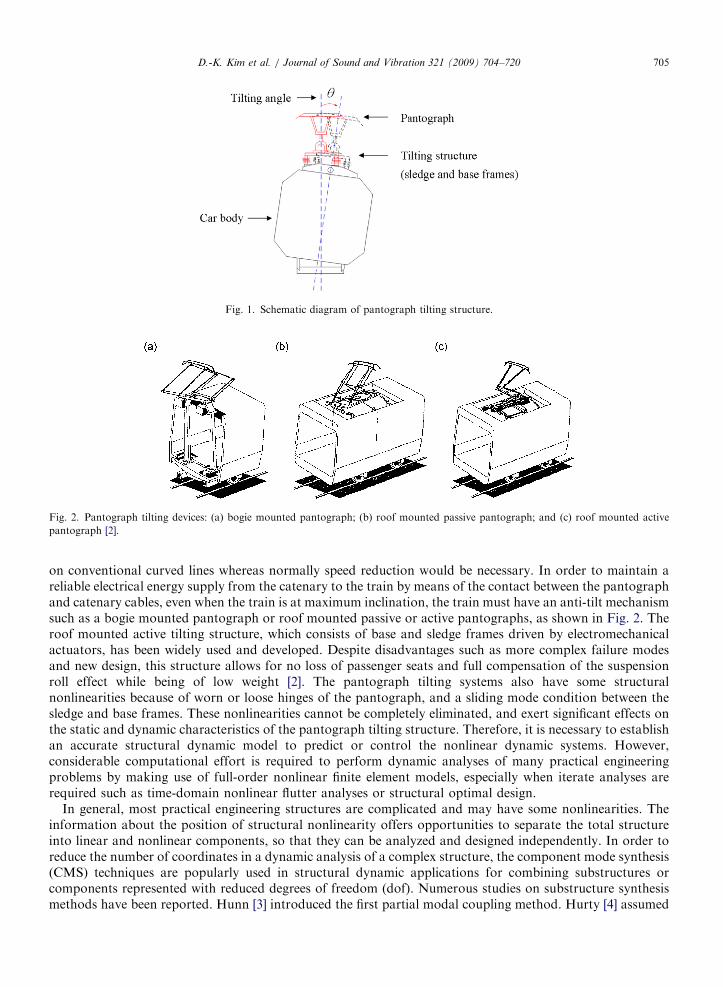
Most practical engineering structures are complicated with distributed or concentrated structuralnonlinearities. For example, a deployable missile control fin has a nonlinear hinge joint that consists of atorsional spring, a compression spring, and several stoppers. Because of wear and manufacturing tolerance,the hinge has some structural nonlinearities such as preload, free-play, asymmetric bilinear stiffness, hysterisis,and coulomb damping [1]. Another example is a pantograph tilting system consisting of a pantograph and atilting structure. The pantograph tilting system is currently being used in tilting trains, which are becoming thestandard internationally, especially in Europe. The car body of a tilting train moving on a curved line is tiltedinward to compensate the centrifugal force, as shown in Fig. 1. Therefore, the speed and run can be increased
ee front matter r 2008 Elsevier Ltd. All rights reserved.
v.2008.09.052
ing author. Tel.: +82 42 869 3723; fax: +82 42 869 3710.
ess: [email protected] (J.-H. Han).
ARTICLE IN PRESS
Fig. 1. Schematic diagram of pantograph tilting structure.
Fig. 2. Pantograph tilting devices: (a) bogie mounted pantograph; (b) roof mounted passive pantograph; and (c) roof mounted active
pantograph [2].
D.-K. Kim et al. / Journal of Sound and Vibration 321 (2009) 704–720 705
on conventional curved lines whereas normally speed reduction would be necessary. In order to maintain areliable electrical energy supply from the catenary to the train by means of the contact between the pantographand catenary cables, even when the train is at maximum inclination, the train must have an anti-tilt mechanismsuch as a bogie mounted pantograph or roof mounted passive or active pantographs, as shown in Fig. 2. Theroof mounted active tilting structure, which consists of base and sledge frames driven by electromechanicalactuators, has been widely used and developed. Despite disadvantages such as more complex failure modesand new design, this structure allows for no loss of passenger seats and full compensation of the suspensionroll effect while being of low weight [2]. The pantograph tilting systems also have some structuralnonlinearities because of worn or loose hinges of the pantograph, and a sliding mode condition between thesledge and base frames. These nonlinearities cannot be completely eliminated, and exert significant effects onthe static and dynamic characteristics of the pantograph tilting structure. Therefore, it is necessary to establishan accurate structural dynamic model to predict or control the nonlinear dynamic systems. However,considerable computational effort is required to perform dynamic analyses of many practical engineeringproblems by making use of full-order nonlinear finite element models, especially when iterate analyses arerequired such as time-domain nonlinear flutter analyses or structural optimal design.
In general, most practical engineering structures are complicated and may have some nonlinearities. Theinformation about the position of structural nonlinearity offers opportunities to separate the total structureinto linear and nonlinear components, so that they can be analyzed and designed independently. In order toreduce the number of coordinates in a dynamic analysis of a complex structure, the component mode synthesis(CMS) techniques are popularly used in structural dynamic applications for combining substructures orcomponents represented with reduced degrees of freedom (dof). Numerous studies on substructure synthesismethods have been reported. Hunn [3] introduced the first partial modal coupling method. Hurty [4] assumed

ARTICLE IN PRESSD.-K. Kim et al. / Journal of Sound and Vibration 321 (2009) 704–720706
that the motion of each substructure could be expressed by a linear combination of some component modesconsisting of rigid-body modes, constraint modes, and normal modes. Craig and Bampton [5] treated thedisplacements of substructures as being composed of constraint modes and normal modes. This model isknown popularly as the fixed interface CMS method. Craig and Chang [6,7] developed free and hybridinterface CMS methods employing free interface substructure normal modes supplemented by reducedflexibility to account for the effects of residual modes. Meirovitch and Hale [8,9] introduced admissiblefunctions and vectors to represent the motion of each substructure. Kapel et al. [10–12] suggested fictitiousmasses loaded at interface coordinates of a central substructure of which the connection to the additionalsubstructure is statically determinate. Bourquin and d’Hennezel [13] proposed a reduction procedure based onthe use of interface modes to reduce the number of interface coordinates in the fixed interface CMS method.Tran [14] extended this procedure to the free and hybrid interface methods. Bladh et al. [15] investigated thenumerical instability of the free interface CMS methods due to matrix ill-conditioning and proposed astabilized free interface CMS method. Apiwattanalunggarn et al. [16] extended the fixed interface linear CMSmethod to nonlinear structures by using fixed interface nonlinear normal modes. This approach is valid aslong as the coupling between substructures is relatively weak. Kim et al. [17] extended the Craig–Bamptonmethod to consider concentrated nonlinear hinge springs and then established a nonlinear dynamic model of adeployable missile control fin. Shanmugam and Padmanabhan [18] developed a hybrid CMS method bycombining the fixed interface method and the free interface method, and carried out a rotordynamic analysis.
Over the years studies on train pantograph systems have mostly focused on active control of thepantographs in order to exert constant contact forces between catenaries and pantographs [19–21] as well asmodeling and analyses of the dynamic interactions of the catenary–pantograph systems in conventional highspeed trains [22–25]. As far as the authors are aware, modeling and dynamic analysis of pantograph tiltingsystems have not been documented in the open literature.
In the present study, the extended Craig–Bampton method is improved to take into account not only theconcentrated structural nonlinearities but also the sliding mode condition. In order to verify the extendedcoupling method, a numerical plate model consisting of two substructures and seven torsional springs issynthesized. The extended method is then further improved to consider the sliding mode condition. Theimproved coupling method is applied to a three-substructure-model with structural nonlinearity of slidinglines between the substructures, and the coupled structural model is verified with dynamic results. Finally, anonlinear reduced model of a pantograph tilting structure is established by using the proposed couplingmethod, and the dynamic characteristics are investigated.
2. Substructure synthesis for hinge joints
The substructure synthesis method, extended to consider concentrated nonlinear hinge joints, is summarizedin this section. In order to verify the method, a numerical plate model with two substructures and seventorsional springs is synthesized by using the extended method, and its modal parameters are compared withanalysis data.
2.1. CMS method
To analyze the dynamic characteristics of a complex structure by using the substructure synthesis method, itis necessary to divide the whole structure into a limited number of substructures. Each substructure isconnected to at least one of the other substructures, as shown in Fig. 3.
For an arbitrary linear undamped substructure, the equations of motion of a substructure A are written as
MRR MRI
MTRI MII
" #€uR
€uI
( )þ
KRR KRI
KTRI KII
" #uR
uI
( )¼
0
FI
( )(1)
where {FI} is the vector of forces applied at the interface coordinates by the adjoining substructure. The massand stiffness matrices M and K and the displacement and force vectors u and F are partitioned according tothe interior (R) and interface (I) coordinates of the substructure.

ARTICLE IN PRESS
Structure (A)
Structure (B)
Structure (C)
InterfaceCoordinate
Fig. 3. A scheme of separate structure analysis.
D.-K. Kim et al. / Journal of Sound and Vibration 321 (2009) 704–720 707
The basic assumption in the CMS method is that the displacement of each substructure can be representedby a linear combination of some normal and constraint modes as follows:
uR
uI
( )¼
CN CC
0 I
� � xR
xI
( )(2)
where ½CN �; ½CC �; and xR xIf gT are the normal modes, the constraint modes, and the vector of independent
generalized displacements, respectively. These modes can be obtained by the eigenvalue problem and the staticequilibrium equation described in detail in Refs. [5,17].
The substitution of Eq. (2) into Eq. (1), and pre-multiplication by the transformation matrix of Eq. (2), gives
mðAÞRR m
ðAÞRI
mðAÞTRI m
ðAÞII
" #€xðAÞ
R
€xðAÞ
I
8<:
9=;þ
o2ðAÞR 0
0 kðAÞI
" #xðAÞR
xðAÞI
( )¼
0
FðAÞI
( )(3)
where m is the generalized mass matrix and o2R and kI are the generalized stiffness matrices corresponding to
the interior and interface coordinates, respectively. The size of the matrices in Eq. (3) is the sum of the numberof normal modes used and the number of interface dof.
2.2. Extended substructure synthesis method
For simplicity, it is assumed that the whole structure consists of two substructures (Sub-A and Sub-B), andthere are no external forces applied to the interior coordinates of the substructures. If the two substructuresare coupled by torsional springs located at some of the interface coordinates, the interface coordinates of eachsubstructure can be divided into the coordinates (Ip) with torsional springs and the other coordinates (In). Thegeneralized equations of motion of Sub-A and Sub-B can be expressed as
mðAÞRR m
ðAÞRIn
mðAÞRIp
mðAÞTRIn
mðAÞInIn
mðAÞInIp
mðAÞTRIp
mðAÞTInIp
mðAÞIpIp
26664
37775
€xðAÞ
R
€xðAÞ
In
€xðAÞ
Ip
8>>>><>>>>:
9>>>>=>>>>;þ
o2ðAÞR 0 0
0 kðAÞInIn
kðAÞInIp
0 kðAÞTInIp
kðAÞIpIp
26664
37775
xðAÞR
xðAÞIn
xðAÞIp
8>>><>>>:
9>>>=>>>;¼
0
FðAÞIn
FðAÞIp
8>><>>:
9>>=>>; (4)
mðBÞInIn
mðBÞTInIp
mðBÞTRIn
mðBÞInIp
mðBÞIpIp
mðBÞTRIp
mðBÞRIn
mðBÞRIp
mðBÞRR
26664
37775
€xðBÞ
In
€xðBÞ
Ip
€xðBÞ
R
8>>>><>>>>:
9>>>>=>>>>;þ
kðBÞInIn
kðBÞInIp
0
kðBÞTInIp
kðBÞIpIp
0
0 0 o2ðBÞR
26664
37775
xðBÞIn
xðBÞIp
xðBÞR
8>>><>>>:
9>>>=>>>;¼
FðBÞIn
FðBÞIp
0
8>><>>:
9>>=>>; (5)
The compatibility equations of the interface coordinates (Ip, In) of the two substructures can be written as follows:
fuðAÞIng ¼ fu
ðBÞIng ¼ fuIn
g; fxðAÞIng ¼ fxðBÞIn
g ¼ fxIng (6)
fFðAÞIpg ¼ ½Ky�ðfu
ðBÞIpg � fu
ðAÞIpgÞ ¼ ½Ky�ðfx
ðBÞIpg � fxðAÞIp
g (7)
fFðBÞIpg ¼ �½Ky�ðfu
ðBÞIpg � fu
ðAÞIpgÞ ¼ �½Ky�ðfx
ðBÞIpg � fxðAÞIp
gÞ (8)
ARTICLE IN PRESSD.-K. Kim et al. / Journal of Sound and Vibration 321 (2009) 704–720708
where [Ky] is a diagonal matrix of the torsional spring coefficients according to each Ip. Substitution of Eqs. (6) (7),and (8) into Eqs. (4) and (5), and coupling of these equations gives
mðAÞRR m
ðAÞRIn
mðAÞRIp
0 0
mðAÞTRIn
mðAÞInInþm
ðBÞInIn
mðAÞInIp
mðBÞTInIp
mðBÞTRIn
mðAÞTRIp
mðAÞTInIp
mðAÞIpIp
0 0
0 mðBÞInIp
0 mðBÞIpIp
mðBÞTRIp
0 mðBÞRIn
0 mðBÞRIp
mðBÞRR
26666666666664
37777777777775
€xðAÞ
R
€xIn
€xðAÞ
Ip
€xðBÞ
Ip
€xðBÞ
R
8>>>>>>>>>>>><>>>>>>>>>>>>:
9>>>>>>>>>>>>=>>>>>>>>>>>>;
þ
o2ðAÞR 0 0 0 0
0 kðAÞInInþ k
ðBÞInIn
kðAÞInIp
kðBÞInIp
0
0 kðAÞTInIp
kðAÞIpIpþ Ky �Ky 0
0 kðBÞTInIp
�Ky kðBÞIpIpþ Ky 0
0 0 0 0 o2ðBÞR
2666666666664
3777777777775
xðAÞR
xIn
xðAÞIp
xðBÞIp
xðBÞR
8>>>>>>>>>><>>>>>>>>>>:
9>>>>>>>>>>=>>>>>>>>>>;¼ 0f g (9)
The natural frequencies and eigenvectors of the combined structure with torsional springs can be easilyobtained from Eq. (9), which can be applied to complex structure problems with several substructures.
2.3. Numerical example 1
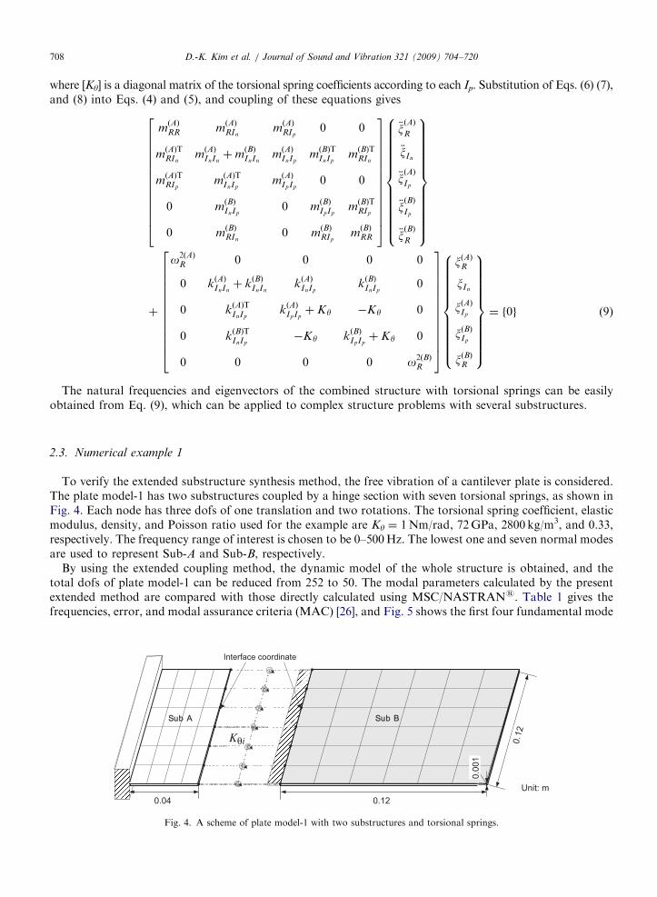
To verify the extended substructure synthesis method, the free vibration of a cantilever plate is considered.The plate model-1 has two substructures coupled by a hinge section with seven torsional springs, as shown inFig. 4. Each node has three dofs of one translation and two rotations. The torsional spring coefficient, elasticmodulus, density, and Poisson ratio used for the example are Ky ¼ 1Nm/rad, 72GPa, 2800 kg/m3, and 0.33,respectively. The frequency range of interest is chosen to be 0–500Hz. The lowest one and seven normal modesare used to represent Sub-A and Sub-B, respectively.
By using the extended coupling method, the dynamic model of the whole structure is obtained, and thetotal dofs of plate model-1 can be reduced from 252 to 50. The modal parameters calculated by the presentextended method are compared with those directly calculated using MSC/NASTRANs. Table 1 gives thefrequencies, error, and modal assurance criteria (MAC) [26], and Fig. 5 shows the first four fundamental mode
Sub A
Interface coordinate
Sub B
Kθi
0.04 0.12
0.12
0.00
1
Unit: m
Fig. 4. A scheme of plate model-1 with two substructures and torsional springs.

ARTICLE IN PRESS
Table 1
Comparison of natural frequency between NASTRAN and present method.
Frequency (Hz), error (%) and MAC
Mode NASTRAN Present Error MAC
1 22.26 22.26 0.000 1.000
2 99.42 99.43 0.004 1.000
3 207.38 207.41 0.016 1.000
4 343.55 344.90 0.392 0.998
5 418.12 418.37 0.059 1.000
6 508.51 509.46 0.188 1.000
7 665.90 679.08 1.979 0.981
8 703.20 708.77 0.792 0.994
Fig. 5. First four fundamental mode shapes of plate model-1.
D.-K. Kim et al. / Journal of Sound and Vibration 321 (2009) 704–720 709
shapes. It is clear that the normal modes of the entire structure are accurately obtained by using the extendedmethod.
3. Substructure synthesis for sliding mode condition
The extended substructure synthesis method described in the previous section is improved to consider thesliding mode condition. For validation of the improved method, it is applied to a three-substructure-modelwith structural nonlinearity of sliding lines between the substructures, and a dynamic analysis of the coupledstructural model is performed for a sinusoidal external force.
3.1. Improved substructure synthesis method
In order to consider the sliding mode condition, it is assumed that there is a sliding mode condition betweenthe substructures, as shown in Fig. 6. The interface coordinates of Sub-A and Sub-B are the guide line and theroller, respectively. The movement of the roller is free along the guide line, but restricted to the perpendiculardirection to the guide line.
If the roller coordinate Ir is located between two interface coordinates, Ii and Ii+1, of the guide line, whichare assumed to be adjacent dofs, then the generalized equations of motion of Sub-A and Sub-B can be

ARTICLE IN PRESS
Substructure A
Substructure BI (A) Interface coordinates (guide line)
I (B) Interface coordinates (roller)r
I (A)
l1
d1
l2
d2
i
I (A) i
I (B) r
I (B) r
I (A) i+1
I (A) i+1
Fig. 6. A scheme of substructure analysis with sliding mode condition.
D.-K. Kim et al. / Journal of Sound and Vibration 321 (2009) 704–720710
expressed in the same manner as Eqs. (4) and (5) as follows:
(10)
mðBÞIrIr
mðBÞRIr
mðBÞTRIr
mðBÞRR
24
35 €x
ðBÞ
Ir
€xðBÞ
R
8<:
9=;þ
kðBÞIrIr
kðBÞRIr
kðBÞTRIr
kðBÞRR
24
35 xðBÞIr
xðBÞR
8<:
9=; ¼
FðBÞIrþ fðBÞIr
fðBÞR
8<:
9=; (11)
where fFðAÞI ig; fF ðAÞI iþ1
g; and fFðBÞIrg are the internal force vectors applied at the guide line (Ii, Ii+1) and the roller
(Ir) by Sub-B and Sub-A, respectively. The external force vectors ffðBÞIrg and {fR
(B)}, which are generated by the
external forces fFðBÞR g applied at the interior coordinates of Sub-B, can be expressed as follows:
ffðBÞIrg ¼ ½CðBÞTC �fF
ðBÞR g (12a)
ffðBÞR g ¼ ½C
ðBÞTN �fF
ðBÞR g (12b)
For synthesis of the substructures, the compatibility equations of the interface coordinates (Ii, Ii+1 and Ir)can be written as follows:
fFðAÞI ig ¼ �
lA2
lA1 þ lA
2
fFðBÞIrg ¼ �cA
i fFðBÞIrg (13)
fFðAÞI iþ1g ¼ �
lA1
lA1 þ lA
2
fFðBÞIrg ¼ �cA
iþ1fFðBÞIrg (14)
fxðBÞIrg ¼ cA
i fxðAÞI ig þ cA
iþ1fxðAÞI iþ1g (15)
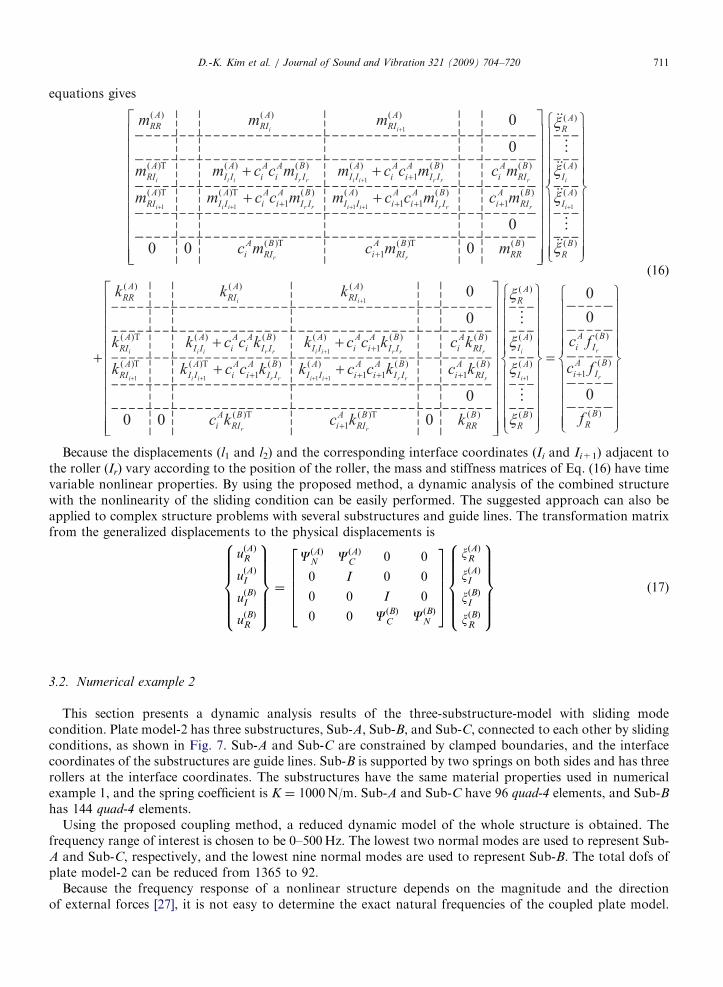
where l1 and l2 are the horizontal displacements between the interface coordinates and the roller, as shownin Fig. 6. Substitution of Eqs. (13),(14), and (15) into Eqs. (10) and (11), and coupling of these
ARTICLE IN PRESSD.-K. Kim et al. / Journal of Sound and Vibration 321 (2009) 704–720 711
equations gives
(16)
Because the displacements (l1 and l2) and the corresponding interface coordinates (Ii and Ii+1) adjacent tothe roller (Ir) vary according to the position of the roller, the mass and stiffness matrices of Eq. (16) have timevariable nonlinear properties. By using the proposed method, a dynamic analysis of the combined structurewith the nonlinearity of the sliding condition can be easily performed. The suggested approach can also beapplied to complex structure problems with several substructures and guide lines. The transformation matrixfrom the generalized displacements to the physical displacements is
uðAÞR
uðAÞI
uðBÞI
uðBÞR
8>>>>><>>>>>:
9>>>>>=>>>>>;¼
CðAÞN CðAÞC 0 0
0 I 0 0
0 0 I 0
0 0 CðBÞC CðBÞN
266664
377775
xðAÞR
xðAÞI
xðBÞI
xðBÞR
8>>>>><>>>>>:
9>>>>>=>>>>>;
(17)
3.2. Numerical example 2
This section presents a dynamic analysis results of the three-substructure-model with sliding modecondition. Plate model-2 has three substructures, Sub-A, Sub-B, and Sub-C, connected to each other by slidingconditions, as shown in Fig. 7. Sub-A and Sub-C are constrained by clamped boundaries, and the interfacecoordinates of the substructures are guide lines. Sub-B is supported by two springs on both sides and has threerollers at the interface coordinates. The substructures have the same material properties used in numericalexample 1, and the spring coefficient is K ¼ 1000N/m. Sub-A and Sub-C have 96 quad-4 elements, and Sub-Bhas 144 quad-4 elements.
Using the proposed coupling method, a reduced dynamic model of the whole structure is obtained. Thefrequency range of interest is chosen to be 0–500Hz. The lowest two normal modes are used to represent Sub-A and Sub-C, respectively, and the lowest nine normal modes are used to represent Sub-B. The total dofs ofplate model-2 can be reduced from 1365 to 92.
Because the frequency response of a nonlinear structure depends on the magnitude and the directionof external forces [27], it is not easy to determine the exact natural frequencies of the coupled plate model.

ARTICLE IN PRESS
Interface coordinates(X, Y, Z)
Roller
Sub-A
Sub-B
Sub-C
Spring, K
Guide line
Interface coordinates(X, Y, Z)
0.04
0.12
Node 66
Node 150
Fy
Fz
Unit [m]
Fig. 7. A scheme of plate model-2 with three substructures and sliding mode condition.
-6
-4
-2
0
2
4
6
Fz, N
Time, sec
0-6
-4
-2
0
2
4
6
Fy, N
1 32 54
0 1 32 54
Fig. 8. Random excitation forces applied at node-150 in y and x directions.
D.-K. Kim et al. / Journal of Sound and Vibration 321 (2009) 704–720712
In order to roughly investigate the natural frequencies of the coupled structure, the random excitation forcesshown in Fig. 8 are applied at the center of Sub-B (node-150) in the y and z-directions. Fig. 9 displays themagnitude of the frequency response functions measured at the collocated node-150 in both directions forexternal random forces, and the lowest five modes can be found.
In order to investigate the dynamic characteristics, dynamic analyses of the reduced plate mode areperformed for three kinds of external forces listed in Table 2. The excitation frequency of force-1 is the firstnatural frequency of 35.2Hz in the y-direction, the frequency of force-2 is 50Hz in both directions, and the

ARTICLE IN PRESS
Table 2
Excitation forces for plate model-2.
Cases Frequency (Hz) Excitation forces (N)
1 35.2 (first resonance) Fy ¼ 0.4 sin(2p� 35.2� t), Fz ¼ 0
2 50.0 (�first/second resonance) Fy ¼ 15 sin(2p� 50� t), Fz ¼ 150 sin(2p� 50� t)
3 104.8 (�second resonance) Fy ¼ 50 sin(2p� 104.8� t), Fz ¼ 5 sin(2p� 104.8� t)
0Frequency, Hz
5th(316.0Hz)
4th(264.4Hz)
3rd(193.8Hz)
2nd(104.8Hz)
FRF-z
FRF-y
1st(35.2Hz)
100 200 300 400 50010-6
10-5
10-4
10-3
10-2
10-1
100
FRF
Mag
nitu
de
Fig. 9. Magnitudes of frequency response functions measured at node-150 for random forces.
D.-K. Kim et al. / Journal of Sound and Vibration 321 (2009) 704–720 713
frequency of force-3 is 104.8Hz, which is close to the second mode in the z-direction. The Newmark betamethod is used to calculate the dynamic response with a time span of 1ms. Fig. 10 shows the dynamicresponses of the coupled model for the external forces. In Figs. 10a,c, the dynamic responses show resonancemotions in the y and z-directions, respectively. The first natural mode shown in Fig. 10a is the sliding motionof the linear mass-spring system consisting of only Sub-B and the supporting springs; the dynamic responsediverges in the y-direction as the time increases. The second natural mode shown in Fig. 10c is mainly theresonance motion in the z-direction, but the motion is coupled with the sliding motion in the y-direction.Therefore, the resonance motion is nonlinear and converges in the z-direction. The dynamic responses forexcitation force-2 are shown in Fig. 10b and Fig. 11, which clearly verify the dynamic connectivity between thesubstructures. From the results, it is noted that the excitation frequencies and the nonlinear dynamiccharacteristics are clearly shown in the responses of the coupled model.
4. Tilting structure with sliding mode condition
A reduced dynamic model of a tilting structure, consisting of sledge and base frames that are connected bythe sliding mode condition, is established using the proposed coupling method. The dynamic responses of thecoupled model for sinusoidal external forces are then analyzed to investigate the nonlinear dynamiccharacteristics of the tilting structure.
4.1. Tilting structure
The tilting structure of a tilting train is attached on the roof of the carriage and supports the pantographsuch that it can maintain the horizontal position of the pantograph while traveling on curved lines. Shown in

ARTICLE IN PRESS
-0.03-0.02-0.010.000.010.020.03
Dz,
m
-0.02
-0.01
Time, sec
0.00
0.01
0.02
Dy,
m
0.0 0.2 0.4 0.6 0.8 1.0
0.0 0.2 0.4 0.6 0.8 1.0
0.0-0.02
-0.01
0.00
0.01
0.02
Dz,
m
Time, sec
0.0-0.02
-0.01
0.00
0.01
0.02
Dy,
m
-0.02
-0.01
0.00
0.01
0.02
Dz,
m
Time, sec
0.0-0.02
-0.01
0.00
0.01
0.02
Dy,
m
0.2 0.4 0.6 0.8 1.0
0.2 0.4 0.6 0.8 1.0
0.2 0.4 0.6 0.8 1.0
0.0 0.2 0.4 0.6 0.8 1.0
Fig. 10. Dynamic responses of plate model-2 measured at node-150: (a) excitation force-1; (b) excitation force-2; and (c) excitation force-3.
D.-K. Kim et al. / Journal of Sound and Vibration 321 (2009) 704–720714
Fig. 12 is the tilting structure for a roof mounted active pantograph, which consists of base and sledgeframes connected with each other under the sliding mode condition. The weights of the base and sledgeframes are 184 and 127 kg, respectively. The sledge frame has three roller sets restricted to follow twoguide lines of the base frame fixed on the roof using 10 fixing points. The maximum displacement of therollers on the guide lines is limited to 7322.5mm along the guide lines. The frame is connected by twomain springs attached on both sides of the base frame to maintain its neutral position without externalforces, and is driven by the main belt, which transmits the driving force from the electric motor to theframe.
In order to establish a reduced dynamic model of the tilting structure, the structure is divided into twosubstructures, substructure A (base frame) and substructure B (sledge frame). The material of the frames isSS400 and its properties are listed in Table 3. MSC/PARTRANs is used to construct the finite elementmodels of the substructures, as shown in Fig. 13a. Sub-A has 512 tria-3 and quad-4 elements, and Sub-B has259 tria-3 and quad-4 elements. The total dofs of Sub-A and Sub-B are 2683 and 1422, respectively. Thefrequency range of interest of the tilting structure is 0–100Hz. Thus, the first seven and nine modes are used to

ARTICLE IN PRESS
Fig. 11. Dynamic response motions of plate model-2 for excitation force-2.
Fig. 12. 3D CAD model of the tilting structure.
Table 3
Material properties of Sub-A and Sub-B.
SS400
Density 7.85 g/cm3
Tensile ultimate strength 400–500Mpa
Tensile yield strength 250Mpa
Modulus of elasticity 200Gpa
Poisson ratio 0.26
Shear modulus 79.3Gpa
D.-K. Kim et al. / Journal of Sound and Vibration 321 (2009) 704–720 715

ARTICLE IN PRESS
Fig. 13. Substructure models and mode shapes: (a) finite element models, (b) constraint modes, (c) first normal modes (Sub-A: 55.89Hz,
Sub-B: 80.82Hz).
D.-K. Kim et al. / Journal of Sound and Vibration 321 (2009) 704–720716
represent the base and sledge frames, respectively, as shown in Fig. 13c. By using the proposed couplingmethod, a reduced dynamic model of the tilting structure is established as shown in Fig. 14. The total dofs ofthe tilting structure can be reduced from 4105 to 100. The substructures are connected by the sliding modeconditions in the interface coordinates. The main springs are represented by the springs and dampers, andtheir coefficients are 5000N/m and 30N s/m, respectively.
4.2. Dynamic characteristics
The dynamic characteristics of the coupled model are investigated through dynamic analyses of the tiltingstructure excited by three kinds of external forces listed in Table 4. The excitation frequency of force-1 is0.99Hz, which is near to the first natural frequency of the sledge frame in the y-direction, the frequency offorce-2 is 19.8Hz, which is near to the second natural frequency in the x-direction, and these two excitationfrequencies are applied simultaneously in both directions in force-3.

ARTICLE IN PRESS
Table 4
Excitation forces for tilting structure.
Cases Excitation forces (N)
1 Fx ¼ 0, Fy ¼ 100� sin(2p� 0.99� t), Fz ¼ 0
2 Fx ¼ 3000� sin(2p� 19.8� t), Fy ¼ 0, Fz ¼ 0
3 Fx ¼ 3000� sin(2p� 19.8� t), Fy ¼ 100� sin(2p� 0.99� t), Fz ¼ 0
Base Frame
Sledge Frame Node-140
Roller 1
Roller 3
Z
X
Y
Roller 2
Guide Line 1
Guide Line 2Fy (t)
Fx (t)
K
C
Fig. 14. Coupled model of the tilting structure and applied forces.
D.-K. Kim et al. / Journal of Sound and Vibration 321 (2009) 704–720 717
Fig. 15 shows the dynamic displacements of node-140, the center of the sledge frame. The resonance motionof the sledge frame in the y-direction is shown in Fig. 15a. The horizontal displacement of the sledge framediverges in the y-direction as the time increases, and the vertical displacement oscillates with the horizontalposition of the sledge frame due to the sliding mode condition. Fig. 15b shows the dynamic responses of thesledge frame for force-2. The displacements in the x and z-axes increase rapidly but converge in both directionsas the time increases. Resonant beating phenomena can also be found at less than 5 s. Fig. 15c shows thedynamic responses for force-3. The displacements in the x, y, and z-directions increase gradually, and thendecrease as the time increases, similar to the resonant beating phenomenon. Although the maximummagnitude of the displacement in the x-direction is restricted to 19mm for force-2, it increases up to 102mmfor force-3 because the motion is coupled with sliding motion of the sledge frame in the y-direction. Thedynamic response motions for excitation force-3 are shown in Fig. 16, which clearly verify the dynamicconnectivity between the substructures and the sliding mode condition.
From the results, it is noted that because of the nonlinearity of the sliding mode condition, the resonantfrequencies and responses of the tilting structure vary according to the position of the sledge and themagnitude of external forces. The displacement in the z-direction, which mostly affects the pantograph in itspower collection, can be resonated by external forces in the x and y-directions. Therefore, these nonlineareffects should be considered in the analyses of the dynamic responses of the pantograph tilting system in orderto assure not only efficiency of the power collection but also the safety of the tilting train.

ARTICLE IN PRESS
0-300
-200
-100
0
100
200
300x-axisy-axisz-axis
Dis
plac
emen
ts o
f nod
e-14
0, m
m
Time, sec
Excitation 1-30
-25
-20
-15
-10
-5
0
5
10
15
20
25
Excitation 2
x-axis y-axis z-axis
Dis
plac
emen
ts o
f nod
e-14
0, m
m
Time, sec
-300-250-200-150-100
-500
50100150200250300
Excitation 3
x-axis y-axis z-axis
Dis
plac
emen
ts o
f nod
e-14
0, m
m
Time, sec0
1 2 3 4 5 6 7 8 9 10 0 1 2 3 4 5 6 7 8 9 10
1 2 3 4 5 6 7 8 9 10
Fig. 15. Dynamic responses of the tilting structure measured at node-140: (a) excitation force-1; (b) excitation force-2; and (c) excitation
force-3.
D.-K. Kim et al. / Journal of Sound and Vibration 321 (2009) 704–720718
5. Conclusions
The CMS method is improved to construct a dynamic model of nonlinear structures with the sliding modecondition. For validation of the extended coupling method, numerical plate model-1 consisting of twosubstructures that are connected by seven torsional springs is synthesized, and its modal parameters arecompared with analysis results obtained by MSC/NASTRANs. An improved coupling method is thenproposed to consider the structural nonlinearity of the sliding mode condition. The improved method isapplied to numerical plate model-2 consisting of three substructures that are connected by the sliding modecondition, and the coupled structural model is verified by dynamic results. Finally, using the proposedcoupling method, a reduced nonlinear model of the tilting structure consisting of sledge and base frames isestablished. Dynamic analyses of the tilting structure are performed for resonant external forces, and thenonlinear dynamic characteristics are investigated. The analysis results show that the improved couplingmethod is effectively applicable to the structural analyses of nonlinear structures with not only hinge joints butalso the sliding mode condition. The additional numerical or experimental validations of the present couplingmethod are subjects of future work.

ARTICLE IN PRESS
Fig. 16. Dynamic response motions of the tilting structure for excitation force-3.
D.-K. Kim et al. / Journal of Sound and Vibration 321 (2009) 704–720 719
Acknowledgments
This research was supported by the Korea Railroad Research Institute (KRRI) and Yujin Machinery Ltd.This support is gratefully acknowledged. The first author would like to thank the Brain Korea 21 Projectin 2006.
References
[1] J.S. Bae, D.K. Kim, W.H. Shin, I. Lee, S.H. Kim, Nonlinear aeroelastic analysis of a deployable missile control fin, Journal of
Spacecraft and Rockets 41 (2) (2004) 264–271.
[2] R. Schneider, Pantograph for tilting trains, Current Collection for High Speed Trains Seminar, IEE, (1998) 2/1–2/6.
[3] B.A. Hunn, A method of calculating the normal modes of an aircraft, Quarterly Journal of Mechanics 8 (1955) 38–58.
[4] W.C. Hurty, Dynamic analysis of structural systems using component modes, AIAA Journal 3 (1965) 678–685.
[5] R.R. Craig, M. Bampton, Coupling of structures for dynamic analyses, AIAA Journal 6 (7) (1968) 1313–1319.
[6] R.R. Craig, C.-J. Chang, Free-interface methods of substructure coupling for dynamic analysis, AIAA Journal 14 (11) (1976)
1633–1635.
[7] R.R. Craig, C-J. Chang, On the use of attachment modes in substructure coupling for dynamic analysis, Proceedings of the AIAA/
ASME 18th Structures, Structure Dynamics & Materials Conference, AIAA Paper, Vol.77–405, 1977, pp. 89–99.
[8] A.L. Hale, L. Meirovitch, A general substructure synthesis method for the dynamic simulation of complex structure, Journal of Sound
and Vibration 69 (2) (1980) 309–326.
[9] L. Meirovitch, A.L. Hale, A general dynamic synthesis for structures with discrete substructures, Journal of Sound and Vibration 85
(4) (1982) 445–457.
[10] M. Karpel, M. Newman, Accelerated convergence for vibration modes using the substructure coupling method and fictitious coupling
masses, Israel Journal of Technology 13 (1975) 55–62.
[11] M. Karpel, Efficient vibration mode analysis of aircraft with multiple external store configuration, Journal of Aircraft 25 (8) (1999)
747–751.
[12] M. Karpel, D.M. Raveh, Fictitious mass element in structure dynamics, AIAA Journal 34 (3) (1996) 607–613.
[13] F. Bourquin, F. d’Hennezel, Numerical study of an intrinsic component mode synthesis method, Computer Methods in Applied
Mechanics and Engineering 97 (1) (1992) 49–76.

ARTICLE IN PRESSD.-K. Kim et al. / Journal of Sound and Vibration 321 (2009) 704–720720
[14] D.M. Tran, Component mode synthesis methods using interface modes. Application to structures with cyclic symmetry, Computers &
Structures 79 (2) (2001) 209–222.
[15] R. Bladh, C. Pierre, M.P. Castanier, Numerical instability of classical free-interface component mode synthesis techniques, AIAA
Journal 41 (8) (2003) 1621–1624.
[16] P. Apiwattanalunggarn, S.W. Shaw, C. Pierre, Component mode synthesis using nonlinear normal modes, Nonlinear Dynamics
41 (1/3) (2005) 17–46.
[17] D.K. Kim, J.S. Bae, I. Lee, J.H. Han, Dynamic characteristics and model establishment of deployable missile control fin with
nonlinear hinge, Journal of Spacecraft and Rockets 42 (1) (2005) 66–77.
[18] A. Shanmugam, C. Padmanabhan, A fixed-free interface component mode synthesis method for rotordynamic analysis, Journal of
Sound and Vibration 297 (3/5) (2006) 664–679.
[19] G. Poetsch, J. Evans, R. Meisinger, W. Kortum, W. Baldauf, A. Veitl, J. Wallaschek, Pantograph/catenary dynamics and control,
Vehicle System Dynamics 28 (2/3) (1997) 159–195.
[20] A. Balestrino, O. Bruno, A. Landi, L. Sani, Innovation solutions for overhead catenary–pantograph system: wire actuated control
and observed contact force, Vehicle System Dynamics 33 (2) (2000) 69–89.
[21] A. Levant, A. Pisano, E. Usai, Output-feedback control of the contract-force in high-speed-train pantographs, Proceedings of the 40th
IEEE Conference on Decision and Control, Vol. 2, 2001, pp. 1831–1836.
[22] T.X. Wu, M.J. Brennan, Dynamic stiffness of a railway overhead wire system and its effect on pantograph–catenary system
dynamics, Journal of Sound and Vibration 219 (3) (1999) 483–502.
[23] M. Arnold, B. Simeon, Pantograph and catenary dynamics: a benchmark problem and its numerical solution, Applied Numerical
Mathematics 34 (4) (2000) 345–362.
[24] B. Simeon, M. Arnold, Coupling DAEs and PEDs for simulating the interaction of pantograph and catenary, Mathematical and
Computer Modelling of Dynamic Systems 6 (2) (2000) 129–144.
[25] J.-H. Seo, S.-W. Kim, I.-H. Jung, T.-W. Park, J.-Y. Mok, Y.-G. Kim, J.-B. Chai, Dynamic analysis of a pantograph–catenary system
using absolute nodal coordinates, Vehicle System Dynamics 44 (8) (2006) 615–630.
[26] R.J. Allemang, D.L. Brown, A correlation coefficient for modal vector analysis, Proceedings of first International Modal Analysis
Conference, 1982, pp. 110–116.
[27] A.H. Nayfeh, D.T. Mook, Nonlinear Oscillations, Wiley, NJ, 1979.