Substation Design Volume III - PDHonline.com Design Volume III Conductors & Bus Design ... The...
39
An Approved Continuing Education Provider PDHonline Course E470 (3 PDH) Substation Design Volume III Conductors & Bus Design Instructor: Lee Layton, P.E 2015 PDH Online | PDH Center 5272 Meadow Estates Drive Fairfax, VA 22030-6658 Phone & Fax: 703-988-0088 www.PDHonline.org www.PDHcenter.com
Transcript of Substation Design Volume III - PDHonline.com Design Volume III Conductors & Bus Design ... The...

An Approved Continuing Education Provider
PDHonline Course E470 (3 PDH)
Substation Design
Volume III
Conductors & Bus Design
Instructor: Lee Layton, P.E
2015
PDH Online | PDH Center
5272 Meadow Estates Drive
Fairfax, VA 22030-6658
Phone & Fax: 703-988-0088
www.PDHonline.org
www.PDHcenter.com
www.PDHcenter.com PDHonline Course E470 www.PDHonline.org
© Lee Layton. Page 2 of 39
Substation Design
Volume III
Conductors & Bus Design
Table of Contents
Section Page
Preface ………………………………..….... 3
Chapter 1, Bare Conductors ……………..…. 4
Chapter 2, Rigid Bus Design ……………... 11
Chapter 3, Strain Bus Design …………….. 29
Summary …………………………………. 39
This series of courses are based on the “Design Guide for Rural Substations”,
published by the Rural Utilities Service of the United States Department of
Agriculture, RUS Bulletin 1724E-300, June 2001.

www.PDHcenter.com PDHonline Course E470 www.PDHonline.org
© Lee Layton. Page 3 of 39
Preface
This course is one of a series of thirteen courses on the design of electrical substations. The
courses do not necessarily have to be taken in order and, for the most part, are stand-alone
courses. The following is a brief description of each course.
Volume I, Design Parameters. Covers the general design considerations, documents and
drawings related to designing a substation.
Volume II, Physical Layout. Covers the layout considerations, bus configurations, and
electrical clearances.
Volume III, Conductors and Bus Design. Covers bare conductors, rigid and strain bus design.
Volume IV, Power Transformers. Covers the application and relevant specifications related to
power transformers and mobile transformers.
Volume V, Circuit Interrupting Devices. Covers the specifications and application of power
circuit breakers, metal-clad switchgear and electronic reclosers.
Volume VI, Voltage Regulators and Capacitors. Covers the general operation and
specification of voltage regulators and capacitors.
Volume VII, Other Major Equipment. Covers switch, arrestor, and instrument transformer
specification and application.
Volume VIII, Site and Foundation Design. Covers general issues related to site design,
foundation design and control house design.
Volume IX, Substation Structures. Covers the design of bus support structures and connectors.
Volume X, Grounding. Covers the design of the ground grid for safety and proper operation.
Volume XI, Protective Relaying. Covers relay types, schemes, and instrumentation.
Volume XII, Auxiliary Systems. Covers AC & DC systems, automation, and communications.
Volume XIII, Insulated Cable and Raceways. Covers the specifications and application of
electrical cable.

www.PDHcenter.com PDHonline Course E470 www.PDHonline.org
© Lee Layton. Page 4 of 39
Chapter 1
Bare Conductors
This chapter covers bare conductors and includes material types, ampacities, and connectors.
Conductor Materials
Copper and aluminum are the two major conductor materials used for substation buses and
equipment connections. Both materials can be fabricated into various types of flexible or rigid
conductors. The trend in substation construction is toward use of mostly aluminum conductors.
Copper conductors are used principally for expansion of similar systems in existing substations.
The conductivity of aluminum is from 50 to 60 percent that of copper, depending on the
aluminum alloy. Consequently, larger aluminum conductors are required to carry the same
currents as copper conductors. The larger aluminum conductor diameters result in greater wind
and ice loads but tend to minimize corona, which is more of a problem at higher voltages.
For the same ampacity, copper conductors weigh approximately twice as much as aluminum
conductors. The higher copper conductor weights can result in more sag as compared with
aluminum conductors for equal spans. To reduce the sag, it is usually necessary to increase the
number of supports for rigid conductors or, in the case of flexible conductors, increase the
tensions.
Rigid Conductors
Rigid electrical conductors are available in a variety of shapes and sizes to suit individual
requirements. Some of the more commonly used shapes include flat bars, structural shapes, and
tubes. Specific physical and electrical properties and application data can be obtained from the
conductor manufacturers.
Flat bars can be utilized for outdoor substation buses and are particularly suitable since they can
be easily bent and joined. For high-current applications, a number of flat bars can be grouped
together, leaving a small space between the bars to facilitate heat dissipation. The ampacity of a
group of flat bars depends on whether the bars are arranged vertically or horizontally. The
number of bars that can be grouped together is limited because of skin and proximity effects. Flat
bars are usually limited to use at lower voltages because of corona.
Because of their inherent lack of rigidity, supports for flat bar buses are usually closely spaced to
minimize the effects of meteorological loads and short-circuit forces.

www.PDHcenter.com PDHonline Course E470 www.PDHonline.org
© Lee Layton. Page 5 of 39
The structural shape conductors that have been used in outdoor substation construction consist
primarily of angle and channel types. The flat surfaces permit bolting directly to support
insulators and provide convenient connection points. To increase ampacity, two angles or
channels can be used. Special fittings are usually required for these configurations. The
positioning and grouping of structural shapes have limitations similar to those of flat bars. The
rigidity of both angle and channel shapes is somewhat higher than for flat bars of the same
ampacity. Consequently, support spacing can usually be increased.
Square and round tubular shapes are considerably more rigid than either flat bars or structural
shapes of the same ampacity and permit longer spans. The flat surfaces of square tubes provide
convenient connection and support points. To facilitate heat dissipation, ventilation holes are
sometimes provided in the square tubes. Round tubular conductors are the most popular shape
used in outdoor substation construction. The round shape is very efficient structurally and
electrically and minimizes corona at higher voltages. The special fittings required for connecting,
terminating, and supporting round tubular conductors are widely available.
Special shapes combining the advantages of several of the standard shapes are also available.
Integral web channel buses, uniform thickness angles, and other special configurations can be
furnished.
Aluminum conductors are available in a variety of alloys and tempers with different conductor
conductivities and strengths. Round tubular conductors are usually specified as either 6061-T6 or
6063-T6 alloy. The 6063-T6 alloy has a conductivity approximately 23 percent higher and a
minimum yield strength approximately 29 percent lower than the 6061-T6 alloy. Consequently,
the 6063-T6 alloy can carry higher currents but may require shorter support intervals. Both
Schedule 40 and 80 pipe are available in either alloy. The Schedule 80 sizes have wall
thicknesses approximately 40 percent thicker than the Schedule 40 sizes, resulting in lower
deflections for equal span lengths.
Alloy 6106-T61 is frequently utilized for flat bars, structural shapes, and square tubes. Other
alloys and tempers are available for special
applications.
Flexible Conductors
Flexible electrical conductors can be used as
substation buses and equipment taps. The
conductors are normally cables fabricated by
stranding a number of small conductors into one
larger conductor. Stranding provides the required

www.PDHcenter.com PDHonline Course E470 www.PDHonline.org
© Lee Layton. Page 6 of 39
conductor flexibility while maintaining strength. The flexibility can be increased by reducing the
diameter and increasing the quantity of individual conductors. Bare electrical cables for
substation construction are usually concentric lay stranded with Class A or AA stranding in
accordance with ASTM Std. B231.
Most flexible conductors used in substation construction consist of all copper, all aluminum, or
aluminum with steel reinforcing (ACSR). The conductor type selected for a particular
application is usually based on the span length, tension and tolerable sag, and cost. For long
spans, large supporting structures will be required. The size and cost of these structures may
depend on the conductor type and should be considered during the selection process.
Flexible conductors are available in many sizes. Size selection is based on ampacity, strength,
weight, and diameter. Conductor diameter becomes increasingly important at higher voltages
where corona can be a problem. Data concerning the physical and electrical properties of the
various wire types can be found in manufacturers’ literature.
Conductor Ampacity
The ampacity of bare conductors is based on a number of factors, including the conductor
material, proximity of the conductors, climatic conditions, conductor temperature rise,
emissivity, and altitude.
Copper conductors can carry about 1.3 or more times as much current as aluminum conductors
of the same size. However, based on weight, more than twice as much copper is required for the
same ampacity.
The current distribution of closely spaced conductors is affected by their mutual inductance in
accordance with the proximity effect. The additional losses attributed to this effect can usually be
neglected if conductor spacing is 18 inches or greater.
Climatic conditions have a great effect on conductor ampacity. Ampacities are usually
determined based on ambient temperatures of 40C. For prolonged ambient temperatures above
this value, ampacities are usually reduced. Wind tends to reduce the temperature of outdoor bare
conductors. An assumed steady wind may be reasonable in many areas. The sun’s radiation can
cause the temperature of bare conductors to increase, which results in lower ampacities and
should be considered in predominately sunny locations.
Conductor temperature rise is the temperature increase above ambient at which the conductor is
operating. To prevent excessive surface oxidation and possible damage from annealing, the
temperature rise is usually limited to 30C for a total maximum conductor temperature of 70C
www.PDHcenter.com PDHonline Course E470 www.PDHonline.org
© Lee Layton. Page 7 of 39
under normal operating conditions. The trend is toward higher operating temperatures.
Temperature rises of 50C and higher have been used successfully. However, temperatures that
could damage the conductors or connected equipment should be avoided.
The conductor surface emissivity has an effect on conductor ampacity. For aluminum
conductors, emissivity is usually taken as 0.5 and for copper conductors 0.8. Both of these values
are for heavily weathered conductor surfaces. The ampacity is usually higher for greater
emissivity.
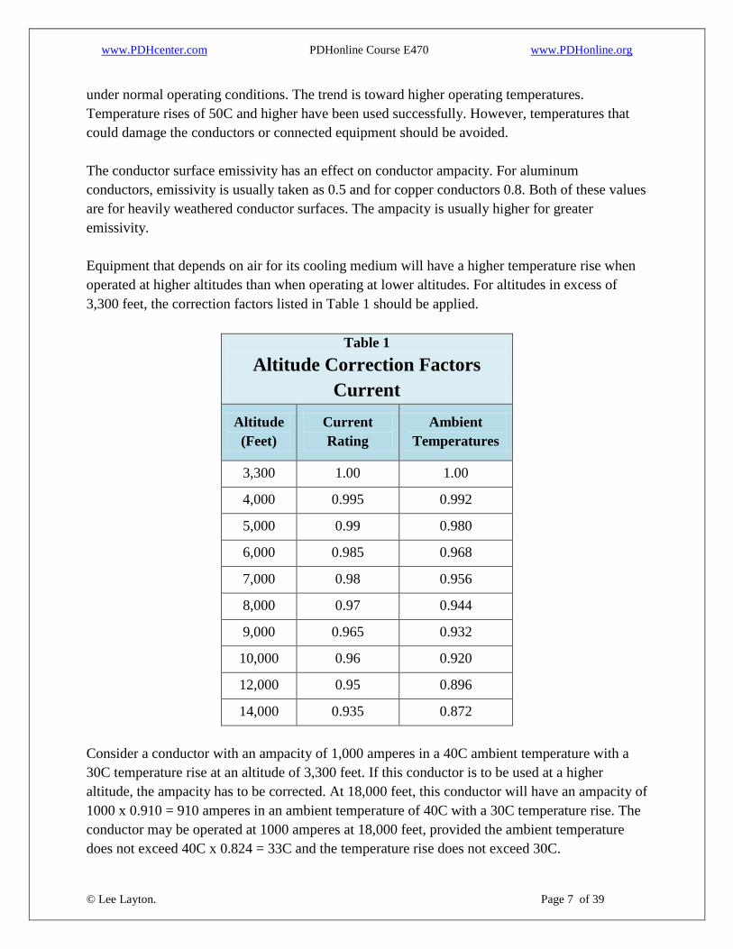
Equipment that depends on air for its cooling medium will have a higher temperature rise when
operated at higher altitudes than when operating at lower altitudes. For altitudes in excess of
3,300 feet, the correction factors listed in Table 1 should be applied.
Table 1
Altitude Correction Factors
Current
Altitude
(Feet)
Current
Rating
Ambient
Temperatures
3,300 1.00 1.00
4,000 0.995 0.992
5,000 0.99 0.980
6,000 0.985 0.968
7,000 0.98 0.956
8,000 0.97 0.944
9,000 0.965 0.932
10,000 0.96 0.920
12,000 0.95 0.896
14,000 0.935 0.872
Consider a conductor with an ampacity of 1,000 amperes in a 40C ambient temperature with a
30C temperature rise at an altitude of 3,300 feet. If this conductor is to be used at a higher
altitude, the ampacity has to be corrected. At 18,000 feet, this conductor will have an ampacity of
1000 x 0.910 = 910 amperes in an ambient temperature of 40C with a 30C temperature rise. The
conductor may be operated at 1000 amperes at 18,000 feet, provided the ambient temperature
does not exceed 40C x 0.824 = 33C and the temperature rise does not exceed 30C.
www.PDHcenter.com PDHonline Course E470 www.PDHonline.org
© Lee Layton. Page 8 of 39
Bus Connections
It is customary to purchase rigid bus conductors in lengths ranging from 10 feet to 40 feet.
Sections need to be joined together for longer lengths. Taps are required from buses to electrical
equipment. Bus conductors need to be attached to support insulators. For greatest reliability and
lowest cost, fewer connections are best.
The various substation bus connections can be made by using any of four main methods—
bolting, clamping, compressing, and welding—depending on the conductor type and material.
Bolted connections are utilized in connecting two or more flat surfaces together. Clamp-type
connections generally involve the use of special fittings fabricated to permit conductors to be
joined together or connected to other equipment. Compression connections are principally used
for splicing or terminating flexible conductors. Welded connections are used primarily with rigid
aluminum conductors. Weldment fittings are available that eliminate extensive conductor cutting
and shaping prior to welding. Compression fittings are now available for rigid tubular bus.
Whenever connectors are utilized for making electrical connections, they should be equivalent
electrically and mechanically to the conductors themselves. Bolted connections are the primary
means of making connections to equipment terminals. Bolted joints permit the disconnection of
equipment for maintenance or replacement. The most common bolted connection involves
joining a conductor to an equipment terminal. A terminal lug is attached to the conductor by
clamping, compressing, or welding, and the lug is bolted to the equipment terminal.
When a copper conductor is connected to a flat copper or electrical bronze equipment terminal, a
copper or electrical bronze terminal lug is utilized. The lug is usually bolted to the equipment
terminal with a minimum of two ½-inch, 13 threads per inch, high-strength silicon bronze bolts
normally torqued to 40 pound-feet. Silicon bronze flat washers are normally used under both the
bolt heads and the nuts.
When an aluminum conductor is connected to a flat copper or electrical bronze equipment
terminal, an aluminum terminal lug is utilized. The lug is usually bolted to the equipment
terminal with a minimum of two ½-inch, 13 threads per inch, anodized aluminum bolts normally
torqued to 25 pound-feet. The bolts are usually aluminum alloy 2024-T4 and the nuts alloy 6061-
T6. Flat washers of aluminum alloy 2024-T4 are normally used under both the bolt heads and the
nuts. An anti-oxidation compound should also be considered for aluminum connections.
When a copper conductor is connected to a flat aluminum equipment terminal, a copper or
electrical bronze terminal lug is utilized. The lug is usually bolted to the equipment terminal with
a minimum of two ½-inch, 13 threads per inch bolts, normally of stainless steel or tin-plated

www.PDHcenter.com PDHonline Course E470 www.PDHonline.org
© Lee Layton. Page 9 of 39
high-strength silicon bronze. Flat washers of the same material as the other hardware are used
under both the bolt heads and the nuts. Stainless steel spring washers are used between the flat
washers and the nuts. Bolts are torqued to the spring washer manufacturer’s recommendations.
When an aluminum conductor is connected to a flat copper or electrical bronze equipment
terminal, an aluminum terminal lug is utilized. The lug is usually bolted to the equipment
terminal with a minimum of two ½-inch, 13 threads per inch bolts, normally of stainless steel or
tin-plated high-strength silicon bronze. Flat washers of the same material as the other hardware
are used under both the bolt heads and nuts. Stainless steel spring washers are used between the
flat washers and the nuts. Bolts are torqued to the spring washer manufacturer’s
recommendations.
For aluminum–copper connections, the copper component should be installed below the
aluminum component to prevent the copper salts from washing onto the aluminum. Additionally,
the aluminum component should be massive, compared with the copper component. It is
recommended the copper connector be tinned when connecting to aluminum connectors.
A large variety of clamp-type electrical connectors are available for both flexible and rigid
conductors of copper and aluminum. Most clamp-type connectors achieve their holding ability as
a result of tightening a number of bolts. The quantities and sizes of bolts used should be as listed
in NEMA Std. CC1. Copper or electrical bronze connectors should be utilized with copper
conductors. All-aluminum connectors should be used with aluminum conductors.
Compression connections are used in splicing or installing terminal lugs on flexible conductors
and for round tubular aluminum conductors. All-aluminum compression connectors should be
used for aluminum conductors. Copper compression connectors should be used for copper
conductors.
For connection on flexible conductors, installation of compression connectors in a vertical
position with the lug down should be avoided to prevent the entrance of moisture and possible
damage from freezing. Compression connection on rigid or flexible conductors can be made
under any weather condition. The fitting is compressed using a portable hydraulic pump. It
compresses the fitting radially 360 degrees. An inspection gauge is then used to verify that the
connection is acceptable.
Compression connectors should always be installed in strict accordance with the manufacturer’s
instructions concerning the quantity and location of compressions. Connectors designed for a
minimum of two circumferential compressions are recommended.

www.PDHcenter.com PDHonline Course E470 www.PDHonline.org
© Lee Layton. Page 10 of 39
Welded connections are used primarily with round tubular aluminum conductors. Use of the
special fittings available simplifies the procedures to permit faster installation. Properly made
welded connections have resistances that are not appreciably higher than the conductors
themselves to eliminate conductor hot spots. Welded aluminum connections are extensively
used in the construction of large substations. Construction costs are usually slightly less with
welded than clamp-type connections. In smaller installations with fewer connections, it may not
be economically feasible to weld connections.

www.PDHcenter.com PDHonline Course E470 www.PDHonline.org
© Lee Layton. Page 11 of 39
Chapter 2
Rigid Bus Design
The design of a rigid bus system involves many factors. There must be ample clearance to
permit equipment maintenance and removal. The bus must allow entrance of construction and
maintenance equipment into the substation and it is important to plan for future expansion by
sizing and positioning buses to facilitate modifications.
The bus conductors are selected based on
ampacity, physical properties, and cost.
Conductors should be selected that they
have sufficient size and capacity to
withstand system faults and over-currents
without damage from overheating.
During short circuits, large forces can be
developed in the bus system. The rigid bus
design includes consideration of these
forces to prevent damage during short-
circuit conditions. The bus centerline-to-centerline spacing and the short circuit current both
have effects on these forces.
If not properly considered, wind and ice loads can cause extensive damage to bus conductors and
insulators. The usual practice is to consider National Electrical Safety Code loadings as a
minimum. Also consider local conditions since they may necessitate the use of more severe
loading criteria.
Since the number of different insulator ratings is limited, exercise care in the bus layout so that a
practical system is achieved. The strength of the insulators required is based on the total bus
loading and particularly the short-circuit forces.
The sag of the bus conductors must be limited in the design. A flat horizontal system looks much
neater than one with excessive sag. The conductor sag is influenced by the conductor weight and
section modulus, the span length, and the vertical loading.
Long conductor spans can be damaged by vibrations caused by winds. Excessive conductor sag
can add to this problem. Span lengths whose natural frequency is near that set up by a wind that
has a high recurrence should be avoided. Dampering conductors or other devices can be used in
the bus to minimize vibration.

www.PDHcenter.com PDHonline Course E470 www.PDHonline.org
© Lee Layton. Page 12 of 39
As the temperature of the conductors increases, longitudinal expansion occurs. If the bus system
is not provided with means to absorb this expansion, insulators or other connected equipment can
be damaged. A wide temperature range is required to accommodate the bus length when de-
energized at the lowest design temperature up to the maximum bus operating temperature.
Long buses usually require the use of more than one section of conductor. Consequently,
couplers have to be utilized to join the sections together. These couplers have to be properly
located to prevent damage from bus loading and short-circuit forces. Plan the bus system
carefully by considering these aspects and other factors as they may develop.
Procedure for Rigid Bus Design
The following procedure can be used in designing a rigid bus system. Select the material and
size of the bus conductors based on continuous current requirements. In higher voltage systems
with longer bus spans, the structural capabilities of the conductors may be the factor that
determines the conductor material and size. However, the conductors selected have to be capable
of carrying the required continuous current in any case.
Using Tables 2 and 3, determine the bus conductor centerline-to-centerline spacing.
Table 2
Substation Clearances
Nominal
Voltage
(Phase-
to-
Phase)
Max
Voltage
P-P
(kV)
BIL
(kV)
Rigid
Conductors
(in)
Phase
Spacing
Rigid Bus
P-P
(in)
Rigid
Conductors
to Ground
(in)
Overhead
conductors
to Ground
(personnel
safety)
(feet)
Overhead
Conductors
to
Roadway
inside fence
(feet)
7.5 8.3 95 7 18 6 8 20
14.4 15.5 110 15 24 7 9 21
23 25.8 150 15 30 10 10 22
34.5 38 200 18 36 13 10 22
46 48.3 250 21 48 17 10 22
69 72.5 350 31 60 25 11 23
115 121 550 53 84 42 12 25
230 242 1050 89 132 71 15 27
www.PDHcenter.com PDHonline Course E470 www.PDHonline.org
© Lee Layton. Page 13 of 39
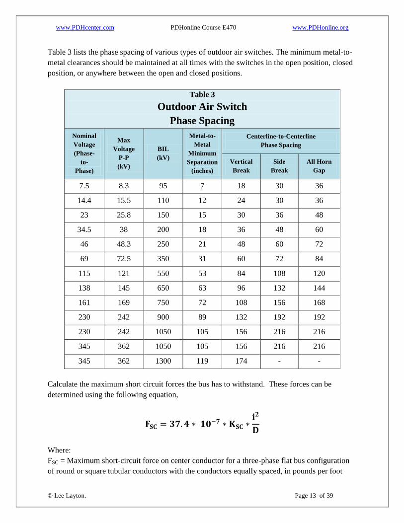
Table 3 lists the phase spacing of various types of outdoor air switches. The minimum metal-to-
metal clearances should be maintained at all times with the switches in the open position, closed
position, or anywhere between the open and closed positions.
Table 3
Outdoor Air Switch
Phase Spacing
Nominal
Voltage
(Phase-
to-
Phase)
Max
Voltage
P-P
(kV)
BIL
(kV)
Metal-to-
Metal
Minimum
Separation
(inches)
Centerline-to-Centerline
Phase Spacing
Vertical
Break
Side
Break
All Horn
Gap
7.5 8.3 95 7 18 30 36
14.4 15.5 110 12 24 30 36
23 25.8 150 15 30 36 48
34.5 38 200 18 36 48 60
46 48.3 250 21 48 60 72
69 72.5 350 31 60 72 84
115 121 550 53 84 108 120
138 145 650 63 96 132 144
161 169 750 72 108 156 168
230 242 900 89 132 192 192
230 242 1050 105 156 216 216
345 362 1050 105 156 216 216
345 362 1300 119 174 - -
Calculate the maximum short circuit forces the bus has to withstand. These forces can be
determined using the following equation,
Where:
FSC = Maximum short-circuit force on center conductor for a three-phase flat bus configuration
of round or square tubular conductors with the conductors equally spaced, in pounds per foot

www.PDHcenter.com PDHonline Course E470 www.PDHonline.org
© Lee Layton. Page 14 of 39
KSC = Short-circuit force reduction factor (0.5 to 1.0; 0.67 recommended)
i = RMS value of three-phase symmetrical short-circuit current, in amperes
D = Centerline-to-centerline spacing of bus conductors in inches
Determine the total bus conductor loading. Table 4 lists values for wind and ice loading for the
various loading districts defined in the National Electrical Safety Code. Consider these values as
minimum. Also consider extreme wind.
Table 4
NESC Conductor
Wind & Ice Loads
Load Loading District
Heavy Medium Light
Radial Thickness of Ice 0.50 0.25 0
Horizontal Wind Pressure (PSF) 4.0 4.0 9.0
Conductor loading is usually based on these criteria. However, in locations where more severe
conditions are frequent, the conductor loading should be based on actual local conditions.
The ice loading can be determined using,
Where:
WI = Ice loading, in pounds per foot
d1 = Outside diameter of conductor with ice, in inches (determine ice thickness from Table 4)
d2 = Outside diameter of conductor without ice, in inches
The wind loading can be determined using,
Where:
FW = Wind loading, in pounds per foot
CD = Drag coefficient (See Figure 1)
PW = Wind pressure, in pounds per foot2 (from Table 4)
d1 = Outside diameter of conductor with ice, in inches
The total bus conductor loading can be determined using,

www.PDHcenter.com PDHonline Course E470 www.PDHonline.org
© Lee Layton. Page 15 of 39
Where:
FT = Total bus conductor loading, in pounds per foot
FSC = Maximum short-circuit force, in pounds per foot
FW = Wind loading, in pounds per foot
WC = Conductor weight, in pounds per foot (if damping cables are used to control conductor
vibration, add the cable weight to the conductor weight)
WI = Ice loading, in pounds per foot
Figure 1 shows the drag coefficients for various structural shapes.

www.PDHcenter.com PDHonline Course E470 www.PDHonline.org
© Lee Layton. Page 16 of 39
Figure 1
The preceding equation applies maximum wind and maximum ice at the same time. NESC and
ANSI/IEEE Std. 605 apply these forces individually, which reduces FT. Engineering judgment
based on site conditions and design loads should determine the maximum loading conditions of
the bus.
Calculate the maximum bus span or support spacing. Maximum bus support spacing can be
determined using,

www.PDHcenter.com PDHonline Course E470 www.PDHonline.org
© Lee Layton. Page 17 of 39
Where:
LM = Maximum bus support spacing, in feet
KSE = Multiplying factor from Table 5
FB = Maximum desirable fiber stress of conductor, in pounds per inch2
For round tubular conductors of:
Copper, FB = 20,000 lb/in2*
6061-T6 aluminum alloy, FB = 28,000 lb/in2*
6063-T6 aluminum alloy, FB = 20,000 lb/in2*
*Includes a safety factor of 1.25.
S = Section modulus of conductor, in inches3
FT = Total bus conductor loading, in pounds per foot
www.PDHcenter.com PDHonline Course E470 www.PDHonline.org
© Lee Layton. Page 18 of 39
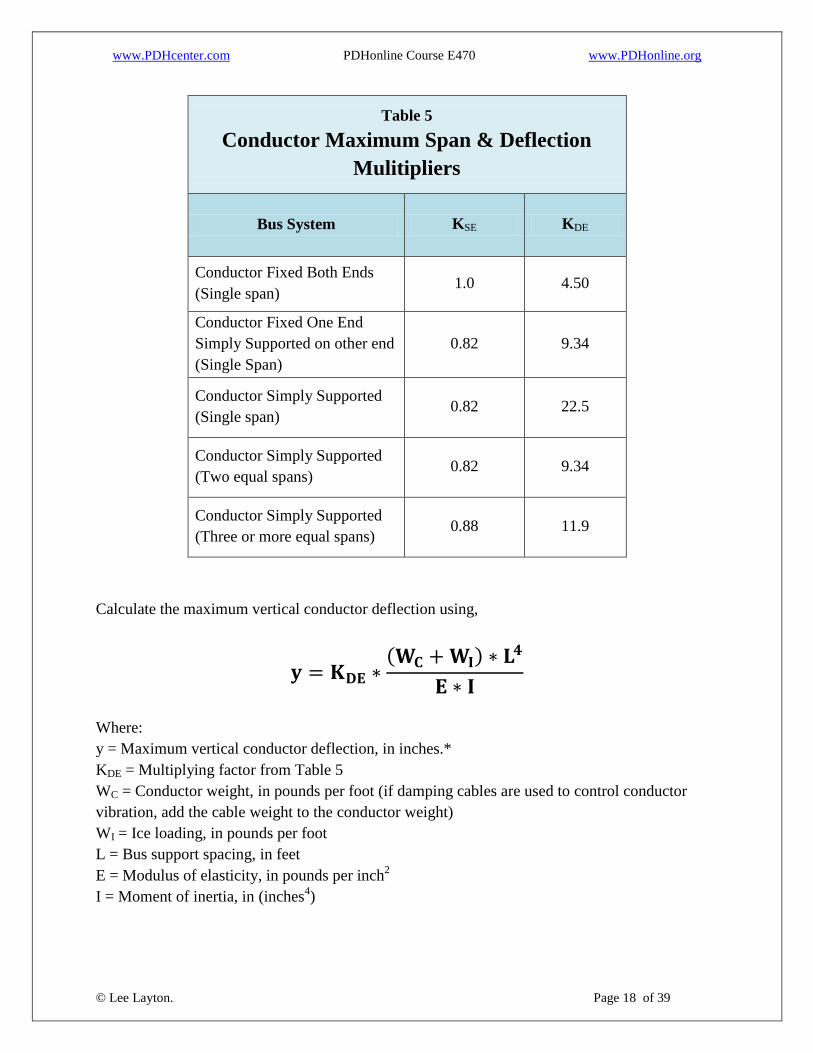
Table 5
Conductor Maximum Span & Deflection
Mulitipliers
Bus System KSE KDE
Conductor Fixed Both Ends
(Single span) 1.0 4.50
Conductor Fixed One End
Simply Supported on other end
(Single Span)
0.82 9.34
Conductor Simply Supported
(Single span) 0.82 22.5
Conductor Simply Supported
(Two equal spans) 0.82 9.34
Conductor Simply Supported
(Three or more equal spans) 0.88 11.9
Calculate the maximum vertical conductor deflection using,
Where:
y = Maximum vertical conductor deflection, in inches.*
KDE = Multiplying factor from Table 5
WC = Conductor weight, in pounds per foot (if damping cables are used to control conductor
vibration, add the cable weight to the conductor weight)
WI = Ice loading, in pounds per foot
L = Bus support spacing, in feet
E = Modulus of elasticity, in pounds per inch2
I = Moment of inertia, in (inches4)
www.PDHcenter.com PDHonline Course E470 www.PDHonline.org
© Lee Layton. Page 19 of 39
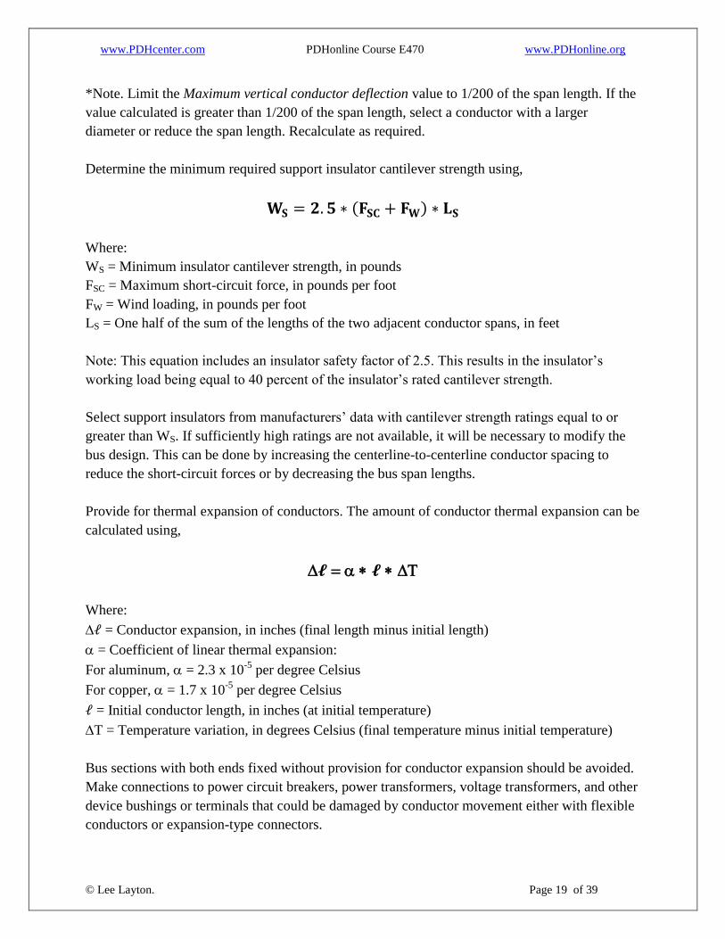
*Note. Limit the Maximum vertical conductor deflection value to 1/200 of the span length. If the
value calculated is greater than 1/200 of the span length, select a conductor with a larger
diameter or reduce the span length. Recalculate as required.
Determine the minimum required support insulator cantilever strength using,
Where:
WS = Minimum insulator cantilever strength, in pounds
FSC = Maximum short-circuit force, in pounds per foot
FW = Wind loading, in pounds per foot
LS = One half of the sum of the lengths of the two adjacent conductor spans, in feet
Note: This equation includes an insulator safety factor of 2.5. This results in the insulator’s
working load being equal to 40 percent of the insulator’s rated cantilever strength.
Select support insulators from manufacturers’ data with cantilever strength ratings equal to or
greater than WS. If sufficiently high ratings are not available, it will be necessary to modify the
bus design. This can be done by increasing the centerline-to-centerline conductor spacing to
reduce the short-circuit forces or by decreasing the bus span lengths.
Provide for thermal expansion of conductors. The amount of conductor thermal expansion can be
calculated using,
Where:
= Conductor expansion, in inches (final length minus initial length)
= Coefficient of linear thermal expansion:
For aluminum, = 2.3 x 10⁻⁵
per degree Celsius
For copper, = 1.7 x 10⁻⁵
per degree Celsius
= Initial conductor length, in inches (at initial temperature)
T = Temperature variation, in degrees Celsius (final temperature minus initial temperature)
Bus sections with both ends fixed without provision for conductor expansion should be avoided.
Make connections to power circuit breakers, power transformers, voltage transformers, and other
device bushings or terminals that could be damaged by conductor movement either with flexible
conductors or expansion-type connectors.

www.PDHcenter.com PDHonline Course E470 www.PDHonline.org
© Lee Layton. Page 20 of 39
Connections to switches utilizing apparatus insulators may require the use of expansion-type
terminal connectors to prevent damage from excessive conductor expansion. Use of expansion-
type terminals in this situation depends on the bus configuration and location of other expansion
points. It is recommended that expansion fittings used on long horizontal buses be limited to
those permitting longitudinal expansion only.
It is usually desirable to limit the length of sections of continuous buses to 100 feet or less to
limit the amount of conductor expansion in each section. This can be done by fixing certain
points in the bus and permitting other points to move freely. An example of a typical bus system
is diagrammed in Figure 2.
Figure 1
The system illustrated in Figure 2 can freely expand as necessary and is free of “captured spans”
that permit no expansion. The locations of slip-fit and fixed bus supports and expansion-type
couplers or bus supports divide the bus into four sections, each of which will expand
approximately the same total amount. If it is desirable to connect the end sections of the bus to
other equipment, provide flexible conductors or expansion-type connectors.
The couplers used on rigid buses should be as long as possible to provide maximum joint rigidity
and strength. Clamp-type bolted couplers should have the quantity and size of clamping bolts
listed in NEMA Std. CC1. Welded couplers for aluminum conductors should be of the internal
type. Compression connectors should be appropriately sized and located. To prevent conductor
damage from bending caused by its own weight and external loads, carefully position couplers.
Welding and bolting can cause appreciable loss of conductor strength in the immediate coupler
locations. Consequently, position couplers where the least amount of bending will occur. The
www.PDHcenter.com PDHonline Course E470 www.PDHonline.org
© Lee Layton. Page 21 of 39
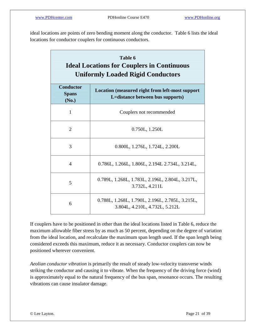
ideal locations are points of zero bending moment along the conductor. Table 6 lists the ideal
locations for conductor couplers for continuous conductors.
Table 6
Ideal Locations for Couplers in Continuous
Uniformly Loaded Rigid Conductors
Conductor
Spans
(No.)
Location (measured right from left-most support
L=distance between bus supports)
1 Couplers not recommended
2 0.750L, 1.250L
3 0.800L, 1.276L, 1.724L, 2.200L
4 0.786L, 1.266L, 1.806L, 2.194L 2.734L, 3.214L,
5 0.789L, 1.268L, 1.783L, 2.196L, 2.804L, 3.217L,
3.732L, 4.211L
6 0.788L, 1.268L, 1.790L, 2.196L, 2.785L, 3.215L,
3.804L, 4.210L, 4.732L, 5.212L
If couplers have to be positioned in other than the ideal locations listed in Table 6, reduce the
maximum allowable fiber stress by as much as 50 percent, depending on the degree of variation
from the ideal location, and recalculate the maximum span length used. If the span length being
considered exceeds this maximum, reduce it as necessary. Conductor couplers can now be
positioned wherever convenient.
Aeolian conductor vibration is primarily the result of steady low-velocity transverse winds
striking the conductor and causing it to vibrate. When the frequency of the driving force (wind)
is approximately equal to the natural frequency of the bus span, resonance occurs. The resulting
vibrations can cause insulator damage.

www.PDHcenter.com PDHonline Course E470 www.PDHonline.org
© Lee Layton. Page 22 of 39
Vibrations will occur in almost all bus spans independently of the conductor material, diameter,
or length. In short spans, the vibrations are usually of small enough magnitude to be neglected.
However, in spans longer than about 20 feet, methods for vibration damping should be
considered.
Two primary methods have been used to dampen aeolian vibrations. The first and most widely
used method consists of installing scrap cables in the horizontal buses. When this method is
used, it is necessary that the cables be loose in the bus tubing to permit vertical movement. If
new cables are used, they should be straightened prior to installation to prevent the cables from
jamming against the tubing sides. Additionally, end caps, preferably of the driven type, should be
installed on the ends of the buses containing the damping cables to prevent horizontal cable
movement out of the tubing. To be effective, damping cables should be installed for the entire
bus length for buses where excessive vibration is suspected.
The second method used to dampen aeolian vibrations consists of installing internal or external
prefabricated bus dampers on the bus conductors. Usually, one damper is installed in each bus
span to control the vibrations. Location and installation should be in accordance with the
manufacturer’s instructions.
Bus Design Example
Design a three-phase rigid bus with the following characteristics:
Total bus length: 150 feet, assuming four equal spans of 37.5 ft
Voltage: 161 kV
BIL: 750 kV
Insulator type: post
Continuous current rating: 1800 amperes
Short-circuit current: 24,000 RMS symmetrical amperes
Altitude: 1,000 ft
NESC loading: heavy
Disconnect switch connected to one end of bus
External prefabricated dampers to control conductor vibration
Step1. Select the material and size of the bus conductors.
Based on the continuous current requirements, 3 in. IPS, schedule 40 6063-T6 aluminum alloy
(1,890 amperes) is selected with the following properties:
WC (weight) = 2.62 lb/ft*; see Table 7

www.PDHcenter.com PDHonline Course E470 www.PDHonline.org
© Lee Layton. Page 23 of 39
d2 (outside diameter) = 3.50 inches; see Table 7
I (moment of inertia) = 3.017 in4; see Table 7
E (modulus of elasticity) = 10 x 106 lb/in
2)
S (section modulus) = 1.72 in3 see Table 7
FB (maximum allowable fiber stress) = 20,000 lb/in2
* If damping cables are to be used to control conductor vibration, the cable weight has to be
added to the conductor weight. In this example, external prefabricated dampers will be used for
vibration control.
Table 7
ASA Schedule 40 Aluminum Pipe Conductor
Physical Properties
Nominal
Pipe Size
(in)
Diameter Wall
Thickness
(in)
Area
(in2)
Weight
per foot
(lb)
Moment
of
Inertia
(in4)
Section
Modulus
(in3)
Radius
of
Gyration
(in) Outside
(in)
Inside
(in)
½ 0.840 0.622 0.109 0.250 0.294 0.017 0.041 0.261
¾ 1.050 0.824 0.113 0.333 0.391 0.037 0.071 0.334
1 1.315 1.049 0.133 0.494 0.581 0.087 0.133 0.421
1 ¼ 1.660 1.380 1.140 0.669 0.786 0.195 0.235 0.540
1 ½ 1.900 1.610 1.145 0.800 0.940 0.310 0.326 0.623
2 2.375 2.067 0.154 1.075 1.264 0.666 0.561 0.787
2 ½ 2.875 2.469 0.203 1.704 2.004 1.530 1.064 0.947
3 3.500 3.068 0.216 2.229 2.621 3.017 1.724 1.164
3 ½ 4.000 3.548 0.226 2.680 3.151 4.788 2.394 1.337
4 4.500 4.026 0.237 3.174 3.733 7.232 3.214 1.510
5 5.563 5.047 0.258 4.300 5.057 15.160 5.451 1.878
6 6.625 6.065 0.280 5.581 6.564 28.150 8.498 2.245
Step 2. Spacing
Determine the bus conductor centerline-to-centerline spacing from Table 2.

www.PDHcenter.com PDHonline Course E470 www.PDHonline.org
© Lee Layton. Page 24 of 39
D (bus centerline-to-centerline spacing) = 108 in.
Step 3. Short Circuit Forces
Short Circuit Forces:
FSC = 13.4 lb/ft2
Step 4. Loading: Determine the total bus conductor loading
From Table 4, Radial thickness of ice: 0.50 in. Horizontal wind pressure: 4.0 lb/ft2.
WI = 2.49 lb/ft
Fw = 1.49 lb/ft
FT = 15.6 lb/ft
Step 5. Calculate the maximum bus support spacing
www.PDHcenter.com PDHonline Course E470 www.PDHonline.org
© Lee Layton. Page 25 of 39
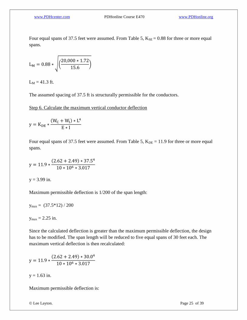
Four equal spans of 37.5 feet were assumed. From Table 5, KSE = 0.88 for three or more equal
spans.
LM = 41.3 ft.
The assumed spacing of 37.5 ft is structurally permissible for the conductors.
Step 6. Calculate the maximum vertical conductor deflection
Four equal spans of 37.5 feet were assumed. From Table 5, KDE = 11.9 for three or more equal
spans.
y = 3.99 in.
Maximum permissible deflection is 1/200 of the span length:
ymax = (37.5*12) / 200
ymax = 2.25 in.
Since the calculated deflection is greater than the maximum permissible deflection, the design
has to be modified. The span length will be reduced to five equal spans of 30 feet each. The
maximum vertical deflection is then recalculated:
y = 1.63 in.
Maximum permissible deflection is:
www.PDHcenter.com PDHonline Course E470 www.PDHonline.org
© Lee Layton. Page 26 of 39
ymax = (30*12) / 200
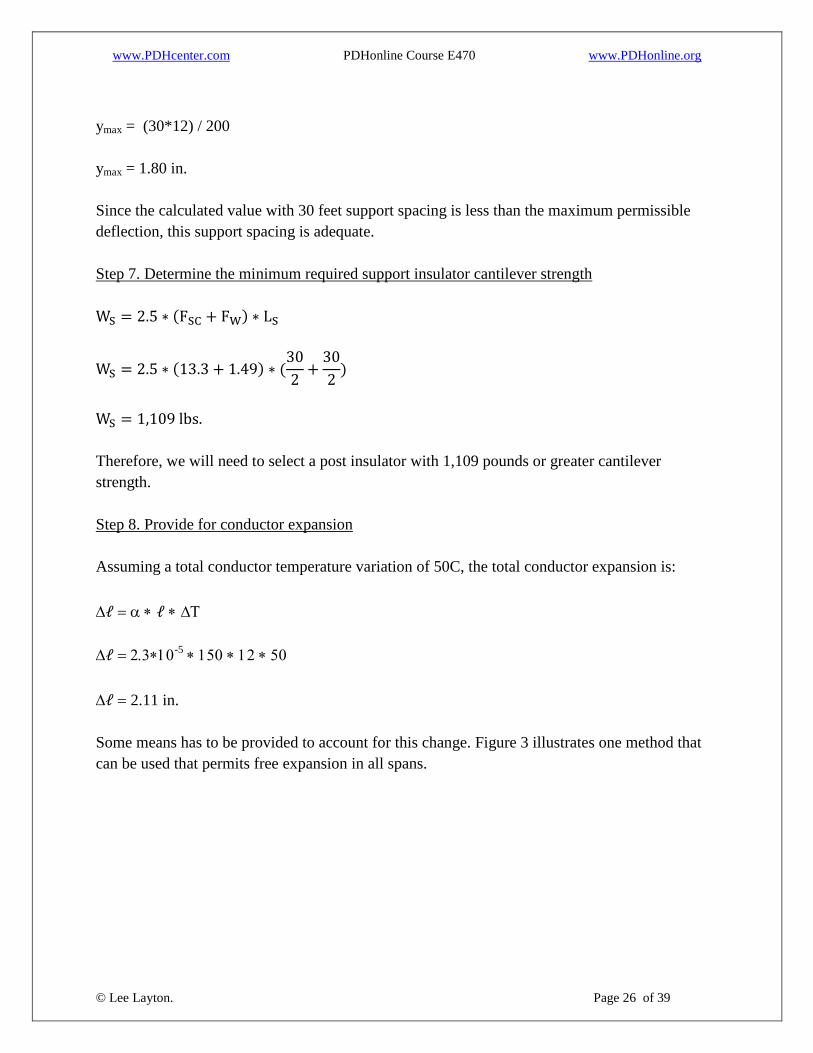
ymax = 1.80 in.
Since the calculated value with 30 feet support spacing is less than the maximum permissible
deflection, this support spacing is adequate.
Step 7. Determine the minimum required support insulator cantilever strength
Therefore, we will need to select a post insulator with 1,109 pounds or greater cantilever
strength.
Step 8. Provide for conductor expansion
Assuming a total conductor temperature variation of 50C, the total conductor expansion is:
-5
2.11 in.
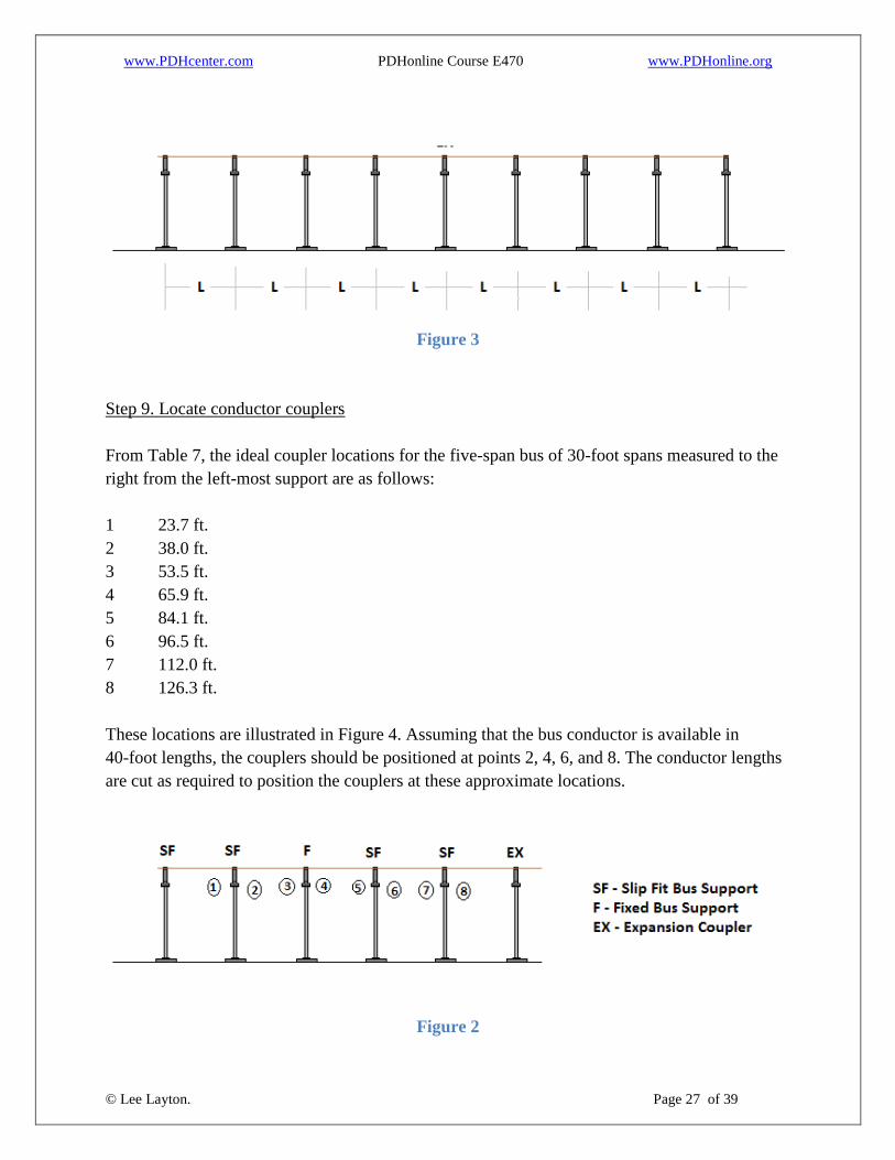
Some means has to be provided to account for this change. Figure 3 illustrates one method that
can be used that permits free expansion in all spans.
www.PDHcenter.com PDHonline Course E470 www.PDHonline.org
© Lee Layton. Page 27 of 39
Figure 3
Step 9. Locate conductor couplers
From Table 7, the ideal coupler locations for the five-span bus of 30-foot spans measured to the
right from the left-most support are as follows:
1 23.7 ft.
2 38.0 ft.
3 53.5 ft.
4 65.9 ft.
5 84.1 ft.
6 96.5 ft.
7 112.0 ft.
8 126.3 ft.
These locations are illustrated in Figure 4. Assuming that the bus conductor is available in
40-foot lengths, the couplers should be positioned at points 2, 4, 6, and 8. The conductor lengths
are cut as required to position the couplers at these approximate locations.
Figure 2

www.PDHcenter.com PDHonline Course E470 www.PDHonline.org
© Lee Layton. Page 28 of 39
Since the spans are fairly long, damaging vibrations may occur. Consequently, a means for
controlling the vibrations should be provided. Prefabricated dampers can be attached to the buses
or scrap cables can be installed in the buses. If cables are used, the cable weight has to be added
to the conductor weight for the bus calculations.

www.PDHcenter.com PDHonline Course E470 www.PDHonline.org
© Lee Layton. Page 29 of 39
Chapter 3
Strain Bus Design
Just like a rigid bus, a strain bus design involves many factors. The flexible conductors used for
strain bus construction permit significant conductor movement. Consequently, the conductors
have to be carefully positioned to prevent contact with other equipment and infringement upon
minimum electrical clearances under all loading and climatic conditions. Equipment
maintenance and removal should also be considered in locating buses and support structures. The
photo below shows a typical strain bus design.
Strain buses usually require large supporting structures. These structures can limit future
expansion if not properly positioned. The conductor is selected based on ampacity, physical
properties, and cost. Conductors have to be selected so that they have sufficient size and capacity
to withstand system faults and overcurrents without damage from overheating.
Wind and ice can increase conductor sags and tensions appreciably. The usual practice is to
consider National Electrical Safety Code loadings as a minimum. Local conditions should be
considered since they may necessitate the use of more severe loading criteria.
The suspension insulators are selected based on the anticipated maximum loading conditions.
The maximum loading for porcelain insulators should not exceed 40 percent of the mechanical–
electrical strength ratings. The maximum loading for fiberglass insulators may not exceed 40
percent of the manufacturer’s strength ratings.
The span length influences the conductor sag. As the span length increases, the sag increases if
the same tension is maintained. To limit the sag, the tensions can be increased. Springs can also
be used to limit the tension and sag.

www.PDHcenter.com PDHonline Course E470 www.PDHonline.org
© Lee Layton. Page 30 of 39
Strain buses are usually positioned above other substation equipment. Conductor breakage could
result in equipment damage or outage. To prevent breakage and to minimize support structure
size, the conductors are usually installed at tensions of approximately 3,000 pounds or less. Sag
may increase because of the deflection of support structures.
Temperature variations cause changes in conductor lengths. As conductor temperature increases,
the sag increases and the tension decreases. Taps from the conductors to other buses or
equipment should be limited in tension to prevent damage to equipment. The taps are usually
installed as slack connections.
Procedure for Strain Bus Design
The following procedure can be used to design a strain bus system:
Select the material and size of the bus conductors, based on continuous current requirements.
Using Tables 2 and 3 determine the bus conductor centerline-to-centerline spacing. The
minimum metal-to-metal, bus centerline-to-centerline, and minimum ground clearances listed in
Table 2 should be increased at least 50 percent for non-rigid conductors.
Select the quantity of suspension insulators from Table 8.
Table 8
Minimum Quantity of
Suspension Insulators
NominalVoltage
(Phase-to-Phase)
BIL
(kV) Qty
7.5 95 1
14.4 110 2
23 150 2
34.5 200 3
46 250 4
69 350 5
115 550 8
161 750 10

www.PDHcenter.com PDHonline Course E470 www.PDHonline.org
© Lee Layton. Page 31 of 39
230 1050 12
Determine the total bus conductor loading. Table 9 lists values for wind and ice loading for the
various loading districts defined in the National Electrical Safety Code. These values should be
considered as minimum.
Table 9
NESC Conductor Loading Criteria
Load Loading District
Heavy Medium Light
Radial Thickness of Ice 0.50 0.25 0
Horizontal Wind Pressure (PSF) 4.0 4.0 9.0
Temperature (C) -20C -10C -1C
Constant (k) added to resultant 4.4 2.5 0.73
Conductor loading is usually based on these criteria. However, in locations where more severe
conditions frequently occur, the conductor loading should be based on actual local conditions.
The ice loading can be determined from,
Where:
WI = Ice loading, in pounds per foot
d1 = Outside diameter of conductor with ice, in inches (determine ice thickness from Table 9)
d2 = Outside diameter of conductor without ice, in inches
The wind loading can be determined using,
Where:
FW = Wind loading, in pounds per foot
PW = Wind pressure, in pounds per foot2 (from Table 9)
d1 = Outside diameter of conductor with ice, in inches (determine ice thickness from Table 9)
Note: the coefficient of drag, Cd, is omitted since it is 1.0 for round conductors.

www.PDHcenter.com PDHonline Course E470 www.PDHonline.org
© Lee Layton. Page 32 of 39
The total bus conductor loading can be determined using,
Where:
FT = Total bus conductor loading, in pounds per foot
FW = Wind loading, in pounds per foot
WC = Conductor weight, in pounds per foot
WI = Ice loading, in pounds per foot
k= NESC constant (from Table 9)
Calculate or obtain the maximum conductor sag. Methods for this calculation can be found in
conductor manufacturers’ literature. In some cases the maximum sag may occur during the most
severe loading condition. For substation strain buses, the design tension is usually limited to
3,000 pounds per conductor under the most severe loading to minimize the size of support
structures. These conductor tensions have to be coordinated with the support structure designs to
ensure compatibility under all loading conditions. The tensions that will occur under unloaded
conditions will be considerably less than the maximum. For light loading conditions where ice
loads are not considered, the maximum conductor sag may occur at the highest conductor
temperature when the conductor length is at a maximum. For other loading conditions, sags
should be determined for both high conductor temperatures and maximum loading so that
adequate clearance from other equipment can be provided.
Calculate the suspension insulator effect on conductor sag.
For short dead-ended spans, such as substation strain buses, the suspension insulators can have
an appreciable effect on span sags. The following procedure can be used to calculate the
insulator effect, which is added to the conductor sag for the total bus sag. See Figure 5.

www.PDHcenter.com PDHonline Course E470 www.PDHonline.org
© Lee Layton. Page 33 of 39
Figure 3
XBD

www.PDHcenter.com PDHonline Course E470 www.PDHonline.org
© Lee Layton. Page 34 of 39
Y1 = YAC - YBC
Y = Y1 + YC
Where:
CI = Insulator catenary constant, feet
CC = Conductor catenary constant, feet
XAC = Horizontal distance from insulator support point to center of insulator catenary, in feet
XBC = Horizontal distance from connection point of insulator string and conductor to center of
insulator catenary, in feet
XBD = Horizontal distance from connection point of insulator string and conductor to center of
conductor catenary, in feet
AB = Length of insulator string, in feet
AC = Arc length from insulator support point to center of insulator catenary, in feet
Y = Total bus sag
YAC = Sag from insulator support point to center of insulator catenary, in feet
YBC = Sag from connection point of insulator string and conductor to center of insulator
catenary, in feet
YI = Insulator sag, in feet
YC = Conductor sag, in feet
y = Total bus sag, including insulators and conductor, in feet
TC = Horizontal conductor tension, in pounds
WIN = Insulator string weight, in pounds per foot
WC = Conductor weight, in pounds per foot
L = Span length, in feet
Calculate and chart stringing tensions and corresponding sags for a range of conductor
temperatures expected during installation. Base the calculations on the assumed maximum
tension that occurs under the most severe conductor loading. Include in the chart and list on the
installation drawings span length, tension, and total bus sag for various conductor temperatures.
Methods to determine the sags and tensions can be found in conductor manufacturers’ literature.
After the conductor sags are calculated, add the suspension insulator sag to the conductor sags to
determine the total bus sags as previously described.

www.PDHcenter.com PDHonline Course E470 www.PDHonline.org
© Lee Layton. Page 35 of 39
Sample Calculation of Bus Conductor Loading
Calculate the total bus conductor loading for the following strain bus:
Span length: 200 feet
Voltage: 161 kV
BIL: 750 kV
Conductor size: 795 kcmil 26/7 ACSR
Conductor diameter: 1.108 in.
Conductor weight: 1.094 lb/ft
NESC loading: heavy
Ice loading: Select ice thickness from Table 9:
Wind Loading: Select wind pressure from Table 7
Total bus conductor loading:
Sample Calculation of Suspension Insulator Effect on Bus Sag
www.PDHcenter.com PDHonline Course E470 www.PDHonline.org
© Lee Layton. Page 36 of 39
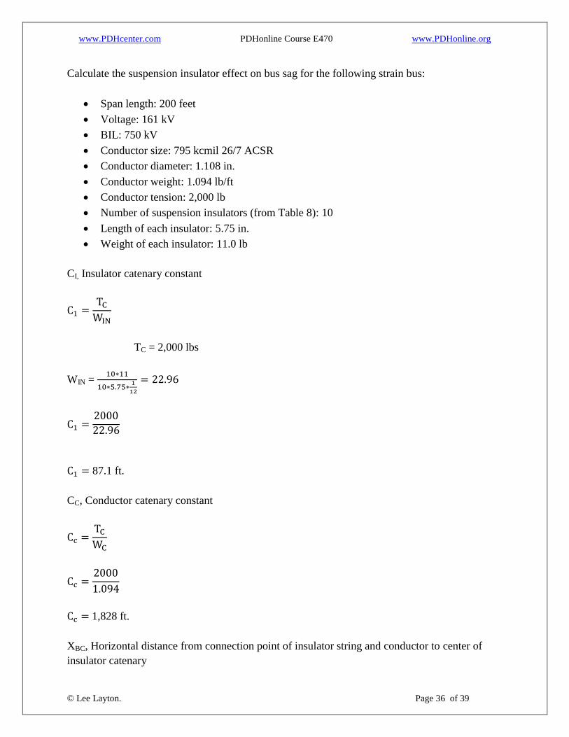
Calculate the suspension insulator effect on bus sag for the following strain bus:
Span length: 200 feet
Voltage: 161 kV
BIL: 750 kV
Conductor size: 795 kcmil 26/7 ACSR
Conductor diameter: 1.108 in.
Conductor weight: 1.094 lb/ft
Conductor tension: 2,000 lb
Number of suspension insulators (from Table 8): 10
Length of each insulator: 5.75 in.
Weight of each insulator: 11.0 lb
CI, Insulator catenary constant
TC = 2,000 lbs
WIN =
87.1 ft.
CC, Conductor catenary constant
1,828 ft.
XBC, Horizontal distance from connection point of insulator string and conductor to center of
insulator catenary

www.PDHcenter.com PDHonline Course E470 www.PDHonline.org
© Lee Layton. Page 37 of 39
4.54 ft.
YBC, Sag from connection point of insulator string and conductor to center of insulator catenary
0.118 ft.
AC, Arc length from insulator support point to center of insulator catenary
9.33 ft.
XAC, Horizontal distance from insulator support point to center of insulator catenary
9.31 ft.
YAC, Sag from insulator support point to center of insulator catenary

www.PDHcenter.com PDHonline Course E470 www.PDHonline.org
© Lee Layton. Page 38 of 39
0.498 ft.
YI , Insulator sag
Y1 = YAC - YBC
Y1 = 0.498 - 0.118
Y1 = 0.38 ft.
The value calculated for YI is then added to the conductor sag to determine the total bus sag. Use
2 * XBD as the span length to calculate the conductor sag.

www.PDHcenter.com PDHonline Course E470 www.PDHonline.org
© Lee Layton. Page 39 of 39
Summary
This volume of the substation design series has focused on conductors and bus design.
Conductors include both rigid and flexible materials and the ampacity and methods of making
connections was covered. In addition the design factors for both rigid and strain bus systems
were reviewed with design examples for each type of bus.
The next course in this series covers the application of power transformers in substations.
Copyright © 2015 Lee Layton. All Rights Reserved.
+++
DISCLAIMER: The material contained in this course is not intended as a representation or warranty on the part
of the Provider or Author or any other person/organization named herein. The material is for general
information only. It is not a substitute for competent professional advice. Application of this information to a
specific project should be reviewed by a relevant professional. Anyone making use of the information set forth
herein does so at his own risk and assumes any and all resulting liability arising therefrom.