Substation Civil Design and Construction Standard · other Standards as applicable. In particular...
49
Tasmanian Networks Pty Ltd (ABN 24 167 357 299) Standard Substation Civil Design and Construction Standard R590634 Version 1.0, June 2018
Transcript of Substation Civil Design and Construction Standard · other Standards as applicable. In particular...

Tasmanian Networks Pty Ltd (ABN 24 167 357 299)
Standard
Substation Civil Design and Construction Standard
R590634
Version 1.0, June 2018

Tasmanian Networks Pty Ltd (ABN 24 167 357 299)
AuthorisationsAction Name and title DatePrepared by Michael Verrier – Senior Asset Strategy Engineer June 2018
Reviewed bySantosh Dhakal –Asset Engineer June 2018
Authorised by Darryl Munro – Asset Strategy Team Leader June 2018Review cycle 30 months
ResponsibilitiesThis document is the responsibility of the Asset Strategy Team, Tasmanian Networks Pty Ltd, ABN 24 167 357 299 (hereafter referred to as "TasNetworks") .
Please contact the Asset Strategy Leader with any queries or suggestions.
• Implementation All TasNetworks staff and contractors.
• Compliance All group managers.
Minimum RequirementsThe requirements set out in TasNetworks ’ documents are minimum requirements that must be compliedwith by all TasNetworks team members, contractors, and other consultants.
The end user is expected to implement any practices which may not be stated but which can be reasonablyregarded as good practices relevant to the objective of this document.
© Tasmanian Networks Pty Ltd 2014
Page 3 of 47
Substation Civil Design and Construction Standard
Record of revisionsSection number Details
Entire doc Copied over verbatim from superseded Transend to TasNetworks template.Updated Transend to TasNetworks document reference numbers where knownincluding Australian Standards.
11.14.1.1 Auxiliary DC lighting details updated
Appendix 3 Added.

Page 4 of 47
Substation Civil Design and Construction Standard
Table of contentsAuthorisations...............................................................................................................................................2
Responsibilities............................................................................................................................................. 2
Minimum Requirements...............................................................................................................................2
List of tables................................................................................................................................................11
List of figures...............................................................................................................................................11
1.....................................................................................................................................................General12
1.1..................................................................................................................................Purpose12
1.2..........................................................................................................................................Scope12
1.3................................................................................................................................Objective12
1.4................................................................................... References, definitions and acronyms12
2...........................................................................................General requirements for civil infrastructure12
2.1......................................................................................................Standard code of practice13
2.2...................................................................................................................... Design loadings13
2.3..............................................................................................Earthing and electrical bonding13
2.4................................................................................Approvals, compliance and notifications13
2.4.1.................................................................................Permits and associated requirements13
2.4.2........................................................................................... Building and plumbing permits14
2.4.3...............................................................................................Infrastructure works permits14
2.4.4...........................................................................................................Fire Service approval14
2.4.5.............................................................................................................Land or landowners14
2.4.6.................................................................................................................. Other approvals14
2.5.........................................................................................Environmental impact assessment14

Page 5 of 47
Substation Civil Design and Construction Standard
2.6..............................................................................................................................Site survey15
2.6.1................................................................................................................................General15
2.6.2.................................................................................................................Survey standards15
2.6.3................................................................................................................................. Datum15
2.6.4....................................................................................................Engineering detail survey15
2.7....................................................................................................Utilities – installed services16
2.8...................................................................................................................................Signage16
3..................................................................................Geotechnical and soil contamination investigation16
4................................................................................................................................................Demolition16
4.1............................................................................................................General requirements16
4.2.................................................................................................................................Asbestos16
5.............................................................................................. Site clearance, excavation and earthworks17
5.1............................................................................................................General requirements17
5.2....................................................................................................................................Batters17
5.3.......................................................................................................................Retaining Walls18
5.4..............................................................................................................................Excavation18
5.5.................................................................................................................Excavated material18
5.6........................................................................................................Compaction of subgrade18
5.7.........................................................................................................Selected or imported fill19
6................................................................................................................................. Roads and surfacing19
6.1............................................................................................................General requirements19

Page 6 of 47
Substation Civil Design and Construction Standard
6.2.........................................................................................Substation roads and loading bays20
6.2.1.......................................................................................................................Access Roads21
6.2.2.................................................................................................................. Perimeter roads21
6.2.3.............................................................................................................. Transformer roads21
6.2.4........................................................................................................................Loading bays21
6.3...............................................................................................................................Pavement22
6.3.1...............................................Materials – base course, sub-base, subgrade, and select fill22
6.3.2...........................................................................................................................Placement22
6.3.3................................................................................Compaction for roads and pavements22
6.4...............................................................................................................Bituminous surfaces23
6.5......................................................................................................... Guard rails and bollards23
7.........................................................................................................................................Substation yard23
8.............................................................................................................................................Site drainage24
8.1.................................................................................General requirements for site drainage24
8.2..................................................................................................Stormwater pipe installation24
8.3..............................................................................................................................Access pits24
8.4...................................................................................................................Kerbs and gutters24
9............................................................................................................................................Water supply25
9.1.................................................................................... Site with access to water reticulation25
9.1.1..................................................................................................................... Isolation valve25
9.1.2..................................................................................Hydrostatic and commissioning tests25

Page 7 of 47
Substation Civil Design and Construction Standard
9.2....................................................................Sites with no access to reticulated water supply25
10..........................................................................................................Concrete and concrete structures26
10.1..........................................................................................................General requirements26
10.2.......................................................................................................... Specific requirements26
10.2.1.....................................................................................................................Surface finish26
10.2.2................................................................................................................Formed surfaces26
10.2.3............................................................................................................Unformed surfaces26
10.3...........................................................................................................Concrete foundations26
10.4..........................................................................................................................Compaction27
10.5....................................................................................................Crack control and jointing27
10.5.1..................................................................................................................Concrete joints27
10.5.2............................................................................................Measures to reduce cracking27
10.6..................................................................................................................... Reinforcement27
10.7...................................................................................................................Moisture barrier28
10.8................................................................................Quality control and testing of concrete28
10.9..............................................................................................................Capacitor bank slab28
11.................................................................................................................................................Buildings28
11.1..........................................................................................................General requirements28
11.2.......................................................................................................... Specific requirements30
11.3.....................................................................................................................Climate control30
11.4............................................................................................................Floor and floor levels31
Page 8 of 47
Substation Civil Design and Construction Standard
11.5.................................................................................................................................. Access31
11.6.....................................................................................................................External facade31
11.7....................................................................................................................Surface finishes31
11.8.................................................................................................................................Roofing31
11.9.................................................................................................................................. Ceiling32
11.10....................................................................................................Guttering and downpipe32
11.11........................................................................................................................... Insulation32
11.12.............................................................................................................. Internal partitions32
11.13................................................................................................. Doors and entrances/exits32
11.14.............................................................................................................................. Lighting33
11.14.1...............................................................................................................Internal lighting33
11.14.2.............................................................................................................. External lighting33
11.14.3..........................................................................................................Emergency lighting34
11.15............................................................................................................Sockets and outlets34
11.16........................................................................................................................Hand railing34
11.17............................................................................................................................... Glazing34
11.18........................................................................................................Indoor fire equipment34
11.19..............................................................................................Bolts and nuts for structures35
11.20........................................................................................... Repairs to galvanized surfaces35
12..........................................................................................................................................Transformers35
12.1..............................................................................................................Transformer plinths35
12.2...............................................................................................................................Firewalls36

Page 9 of 47
Substation Civil Design and Construction Standard
12.2.1...................................................................................General requirements for firewalls36
12.2.2.....................................................................................Design requirements for firewalls36
13........................................................................................................................Oil Containment systems37
13.1.1..........................................................General requirements for oil containment systems37
13.1.2............................................................Design requirements for oil containment systems37
13.1.3..................................................Construction requirements for oil containment systems37
13.1.4.........................................................Watertightness testing for oil containment systems38
13.2................................................................................................................Transformer bund38
13.2.1....................................................................General requirements for transformer bund38
13.2.2......................................................................Design requirements for transformer bund38
13.2.3..................................................................Requirements for transformer bund drainage39
13.3..........................................................................................................Oil containment tanks39
13.3.1..............................................................General requirements for oil containment tanks39
13.3.2................................................................Design requirements for oil containment tanks39
14...............................................................................................................Substation yard fire protection40
14.1..........................................................................................................General requirements40
14.2............................................................................................................Design requirements40
15...................................................................................................................................................Security40
16.................................................................................................................Inspection checks and testing40
16.1.................................................................................................................Inspection checks40
16.1.1.........................................................................................................................Civil works40
Page 10 of 47
Substation Civil Design and Construction Standard
16.1.2........................................................................................................................Earthworks41
16.1.3........................................................................................................... Roads and surfaces41
16.1.4....................................................................................................Concrete and steelwork41
16.1.5...........................................................................................Oil containment and drainage41
16.1.6................................................................................................................Building services42
16.2...........................................................................................................................Civil testing42
16.2.1........................................................................................................................ Roadworks42
16.2.2...........................................................................................................................Materials42
16.2.3.......................................................................................................Water-main/fire-main42
16.2.4...........................................................................................................................Sewerage42
17..........................................................................................Information to be provided with submission42
18............................................................................................................................................Deliverables42
19.............................................................................................................................................Hold Points42
Appendix 1 – References, definitions and acronyms.................................................................................43
A1.1............................................................................................................Australian Standards43
A1.2.................................................................................................................... National Codes44
A1.3............................................................................................................. International Codes44
A1.4.......................................................................................................TasNetworks Standards44
A1.5...............................................................................................DIER Standard Specifications45
A1.6..............................................................................................Abbreviations and definitions45
Appendix 2 – Project parameters...............................................................................................................47
Appendix 3 – Standard Emergency DC light.............................................................................................. 49

Page 11 of 47
Substation Civil Design and Construction Standard
List of tablesTable 1...............................................................................Minimum compaction requirements
23
Table 2................................................................................. Maximum acceptable crack widths27
Table 3.......................................................................................................Minimum clearances30
Table 4..........................................................................................................Project parameters47
List of figuresFigure 1............................................................................................................ Substation roads
20

Page 12 of 47
Substation Civil Design and Construction Standard
1 General
1.1 PurposeTo define the requirements for substation and switchyard civil infrastructure works under the responsibilityof Tasmanian Networks Pty Ltd (hereafter referred to as ‘TasNetworks ’).
1.2 ScopeThis Standard applies to all civil works for permanently located substation sites under the responsibility ofTasNetworks . For all electrical and electrical related work refer to the relevant TasNetworks Standards.
This Standard contains requirements for design, engineering, manufacture, construction, testing atmanufacturer’s works, secured packaging, supply, transportation, delivery to site, testing and commissioningwith complete documentation of civil works and is to be applied to new installations as well asredevelopment of part or all of existing installations.
1.3 ObjectiveThe objective of this standard is to specify the standard for design and construction of substation civilinfrastructure to ensure:
• that the relevant Australian and State legal requirements are met;
• that the requirements of the National Electricity Rules are met;
• personnel and public safety;
• ease in operation and maintenance;
• reliability and continuity of power supply to the power transmission network;
• the implementation of TasNetworks’ strategic performance objectives;
• that an optimised project is designed and delivered; and
• that the customer’s requirements are met.
1.1 References, definitions and acronymsAs a component of the complete specification for a system, this Standard is to be read in conjunction withother Standards as applicable. In particular this includes the project specifications and relevant Standards.References, definitions and acronyms specific to this project are included in Appendix 1.
For the purpose of this Standard substation yard and switchyard are synonymous. That is, any requirementin this Standard for a substation yard is also applicable to a switchyard unless specified otherwise.
2 General requirements for civil infrastructureAll substation civil infrastructures must be designed for a 50 year life unless specified otherwise. All civilengineering, building works and associated services must be suitable for the purposes described in thisStandard and where required associated documentation is to be completed.
The extent of work for the civil engineering, building works and services include the design, supply ofmaterials, construction, installation and testing as required by this Standard.

Page 13 of 47
Substation Civil Design and Construction Standard
The safety of personnel and equipment must at all times be paramount particularly if live overhead lines orunderground cables exist within the construction area.
2.1 Standard code of practiceThe Contractor must design all civil works in compliance with the relevant TasNetworks Standards, AustralianStandards, DIER Standard Specifications (as required), Building Code of Australia (BCA), and LocalGovernment Authority requirements.
Attention must be paid to internal and external access in order to facilitate inspection, cleaning, assetreplacement and maintenance.
All equipment must be designed to minimise the risk of fire and any damage due to vermin.
All items of equipment that may be required to be mechanically lifted for erection or maintenance must beprovided with lifting eyes, jacking pads or alternative handling facilities.
2.2 Design loadingsAll elements must be designed in accordance with the relevant Australian Standards considering the mostunfavourable combination of static, dynamic wind, snow, ice and earthquake loadings. Loadings must bebased on the relevant parts of AS/NZS 1170.
Ultimate limit state wind speeds must be based on a 50 year return period (i.e. 2% probability of beingexceeded in any one year) as per AS/NZS 1170.2.
2.3 Earthing and electrical bondingAll earthing and electrical bonding must be designed to the relevant Australian Standards and TasNetworksStandards with particular attention to TasNetworks Standards R522692 Substation Lightning Protection andEarthing Standard, R522687 General Substation Requirements, and R522697 Temporary Earthing ofSubstation Equipment.
All steel reinforcing must be welded in accordance with Clause 10.6.
All earth connections within the substation yard for apparatus must be connected to the substation yardearth grid. The connection to the associated grading grid will not be accepted.
2.4 Approvals, compliance and notifications
2.4.1 Permits and associated requirementsTasNetworks is responsible for obtaining the following permits:
(a) Planning;
(b) Aboriginal cultural heritage;
(c) Historic heritage; and
(d) Environmental.
TasNetworks is responsible for on-ground planning, heritage and environmental surveys required inobtaining the appropriate permits under relevant Local, State and Commonwealth legislation.
The permits issued to TasNetworks may include conditions that are relevant to the works.

Page 14 of 47
Substation Civil Design and Construction Standard
The Contractor must implement the permit conditions associated with the Planning, Heritage andEnvironmental permits specified in PDR, Substations.
2.1.1 Building and plumbing permitsThe Contractor is responsible for obtaining approvals in relation to buildings, water, sewers and drains fromthe relevant Authority(s) including the engagement of suitably qualified Building Surveyors if necessary.
2.1.2 Infrastructure works permitsThe Contractor is responsible for obtaining approvals under the Local Government (Highways) Act, 1982, andthe Roads and Jetties Act 1935 in relation to works carried out in a public road from the appropriateAuthority(s).
The Contractor is responsible for all costs associated with alterations and connections to existing publicinfrastructure and must obtain written approval from the relevant authority prior to commencing works thataffect the public infrastructure.
2.1.3 Fire Service approvalFull design drawings for the fire-main, fire hydrant and enclosure details and locations must be submitted tothe relevant authorities and their approval obtained in writing prior to any installation work proceeding.
2.1.4 Land or landownersThe Contractor is responsible for any requirements listed in Appendix 2 of the PDR, in relation to land orlandowners impacted by the works under the Contract.
2.1.5 Other approvalsThe Contractor must make all arrangements and obtain all other permits that are necessary to undertake theworks under the Contract, including but not limited to:
(a) workplace safety;
(b) hazardous materials or waste;
(c) dangerous goods;
(d) noise;
(e) soil and water management; and
(f) quarrying.
Approval requirements may be found in Council By-Laws, other Acts and associated Regulations, or Codesand Guidelines.
Prior to commencement of the works, the Contractor must provide to TasNetworks copies of documentaryevidence pertaining to all approvals, permits or certificates obtained and payment of all fees and levies.
2.1 Environmental impact assessmentThe requirements of the EIA, specified in the Contract, must be implemented in accordance with the actionplan of the EIA and TasNetworks Standard D11/52510 – Environmental Impact Assessment and Approvals.

Page 15 of 47
Substation Civil Design and Construction Standard
2.2 Site survey
2.2.1 GeneralTasNetworks will provide ground and cadastral survey information for the site if available. This informationwill be supplied for information purposes only.
The Contractor must acquire all ground and cadastral surveys required to complete the design andconstruction of the contract works.
Each survey type must be a separate model as either:
(a) GENIO data file; or
(b) 3D AutoCAD Drawing.
2.1.1.1 Qualification of SurveyorsAll surveys must be the responsibility of a qualified surveyor. All surveyors must be able to demonstratecompetence in carrying out the required survey tasks.
2.1.2 Survey standardsThe technical survey standards applying to the class of all horizontal and vertical controls required under thisStandard are contained in ICSM SP1.
2.1.3 DatumThe horizontal datum for all surveys should be the national datum to ensure seamless integration with allother National and State datasets. Currently this is GDA94, with survey data to be provided in MGAcoordinates. The vertical datum for all surveys should be Australian Height Datum 83 (AHD 1983).
A statement of the average Combined Scale Factor (CSF) to be applied to convert from GRID to GROUNDdistances must be clearly shown on all sheets of the detail survey and design plans, where the survey controlcoordinates are displayed.
2.1.4 Engineering detail survey
2.1.4.1 GeneralEngineering detail surveys must include all features, ground levels, overhead and underground serviceswhere determinable by lifting of pit covers. All points that represent a single feature must be a single string.
RTK GPS is not to be used to capture information for a building or any feature where the horizontal distanceor height difference tolerance is less than ±0.05 m.
2.1.4.2 UtilitiesThe Contractor is responsible for proving the actual locations and level of all utilities prior to undertaking anywork which may affect the utilities. Evidence of Compliance must include records of ‘Dial before you Dig’contact which must be supplied within two (2) days of being requested by TasNetworks .
The Contractor must liaise with the appropriate utility owner to determine the exact location of each utilityand any conditions that are required by the utility owner.
The Contractor must adhere to any requirements of the responsible utility owner in the execution of thework.

Page 16 of 47
Substation Civil Design and Construction Standard
2.2 Utilities – installed servicesThe Contractor must protect and maintain the serviceability of all installed services. The cost of any repairsor damage is to be borne by the Contractor.
Any fees required for locating or relocating these services are at the Contractor’s cost.
2.3 SignageThe Contractor must provide and install all requisite signage on substation infrastructure and equipment inaccordance with R517372 Substation Signage Standard.
3 Geotechnical and soil contamination investigationThe Contractor must refer to the project specification for results of geotechnical and soil contaminationtesting that may have been undertaken by TasNetworks . This information is provided for informationpurposes only. The Contractor is responsible for interpreting and assessing the information provided anddetermining whether additional geotechnical investigations are required to complete the work specified inthe project specifications. TasNetworks assumes than the Contractor has undertaken an independentevaluation of the geotechnical information and a site inspection by a qualified geotechnical engineer beforelodging a submission.
Further investigation by the Contractor for soil contamination may be required to satisfy permit conditionsand the EIA.
The Contractor must undertake all further geotechnical investigations required to fully design and constructthe work specified in the project specifications and ensure the installation is structurally sound over itsdesign life.
All geotechnical investigations must be carried out prior to commencement of demolition or construction.
4 Demolition
4.1 General requirementsAll demolition work is to be undertaken in accordance with AS 2601.
The Contractor must prepare a work plan complying with Clauses 1.3.25 and 2.3 (Work Plan) of AS 2601. Thework plan must be submitted to and approved by TasNetworks prior to commencement of demolition.
Unless specified otherwise the removal of structures must include the following works:
(a) Removal of all redundant underground pipes;
(b) Removal of all redundant concrete slabs and other paving; and
(c) Removal of all redundant foundations to a minimum of 100 mm below FSL.
All materials from the demolition must be removed from site within seven days of completion of thedemolition of each structure.
4.1 Asbestos

Page 17 of 47
Substation Civil Design and Construction Standard
Where TasNetworks has advised of the presence of asbestos, or where asbestos is identified prior to orduring the performance of work on site, the Contractor must comply with the requirements of R472616Asbestos Management and Control in the Workplace.
5 Site clearance, excavation and earthworks
5.1 General requirementsThe following general requirements are applicable to all site clearance, excavation and earthworks:
(a) All site clearance, excavation and earthworks necessary to provide a suitable surface for theconstruction, installation and future operation and maintenance of the installation and its equipment,must be performed;
(b) The finished substation yard level will have a maximum fall of 1 in 75 in any direction and therequirements of Clause 8.1;
(c) The site may be benched where required to achieve the requirement in (b). Where it is impractical toachieve these requirements for a given site or part of a site, practical alternatives must be presentedto TasNetworks for approval;
(d) The Contractor must dispose of all surplus excavated material. No excavated material is to be placedonto any properties without the written consent of the property owners;
(e) Where a site contains contaminated soil, the requirements for treatment of the contaminated soilmust be taken into account to ensure that the soil is treated in accordance with the requirementsoutlined in the EIA;
(f) Appropriate steps must be undertaken to ensure water flowing through the property will not conveysilt downstream, either through drains or overland, onto adjacent properties; and
(g) Appropriate steps must be undertaken to ensure any altered water flows do not lead to erosion.
All topsoil within the footprint of the earthworks is to be stripped prior to the commencement of bulkexcavation or the placement of embankments. The stripping depth is to be a minimum of 100 mm unlessspecified otherwise. The topsoil is to be used to rehabilitate excavation and embankment batters whereappropriate. All excess topsoil is to be disposed of by the Contractor.
The Contractor must make allowance for stripping in determining the quantity of embankment materialrequired.
5.1 BattersAll batters must be sloped and treated to ensure the long-term stability of the material and to prevent anycollapse of material or foundations.
Grassed and/or soft landscaped batters are only permitted outside the security fence.
Unless specified otherwise by TasNetworks , grassed embankment batters must be designed and constructedso that the grass will grow in and stabilise the batter in the long term using a combination of subsoilenhancement, topsoiling, hydromulch, jute mat application and hydroseeded. The seed mix must beappropriate to the site.
Excavation batters in any material other than rock are to have a maximum slope of two horizontal to onevertical unless shown otherwise to be stable and accepted by TasNetworks .
Excavation batters in rock must be sloped to take into account the characteristics of the rock.

Page 18 of 47
Substation Civil Design and Construction Standard
Where softer rock types exist which are subject to erosion due to an altered state, the Contractor mustdetail the proposed treatments and implement accordingly after receiving TasNetworks’ approval.
Where it is impractical to provide batters to the slopes specified above due to ground topography,equipment space restrictions or adjacent property restrictions suitable retaining walls must be constructedto form the required surface levels of the substation yard.
5.2 Retaining WallsRetaining walls must be installed in accordance with manufacturer’s recommendations suitable for thespecific application. All retaining walls must be a low maintenance type and drainage layers must beprovided along the full length of the installation.
All retaining walls must be designed in accordance with the requirements of AS 4678.
5.3 ExcavationThe following requirements apply to excavation work:
(a) All excavation works must comply with the minimum requirements of D05/44571 Excavation Standard;
(b) Excavate all material necessary to achieve the finished substation yard surface level and the levelrequired for foundations for buildings and equipment;
(c) All excavations must be performed to an even surface under foundations and vehicular roads so thatfuture differential settlement is avoided;
(d) All excavation must be undertaken within the site to the dimensions necessary to allow for works tobe properly and conveniently carried out;
(e) Excavation must be neat and square with batters suitable for the exposed material and level bottoms,consolidated where necessary to receive new work;
(f) All strutting and shoring necessary for safe execution of the works must be provided; and
(g) All subgrade areas must be trimmed so that the top surface of the subgrade is free drainage.
5.1 Excavated materialSound excavated material may be used for filling or backfilling where the material complies with thisStandard.
Bad ground, which is defined as unsuitable for the work, includes:
(a) fill or natural ground liable to subsidence;
(b) containing cavities, faults or fissures;
(c) ground contaminated by harmful substances; and
(d) ground which is or becomes soft or unstable and must be excavated and unless otherwise approvedby TasNetworks , removed from site and disposed of in accordance with D04/10174 WasteManagement Procedure. Where necessary, material must be imported to replace any unsuitablematerial and establish foundation levels.
5.1 Compaction of subgradeFollowing completion of subgrade compaction and trimming, the whole subgrade area must:

Page 19 of 47
Substation Civil Design and Construction Standard
(a) be proof rolled with a fully loaded single rear axle truck (Medium Rigid). Acceptance requires novisible signs of deformation or instability in the subgrade during proof rolling;
(b) where tested with a Blenkelman Beam, acceptance requires a characteristic deflection of less than 2 mm; and
(c) meet the requirements of Clause 6.3.
5.1 Selected or imported fillAll material used for embankment construction must be free of vegetation or other deleterious matter.
All selected or imported material used in embankments, filling of excavated areas and any other areas mustbe compacted to meet the design requirements, the intended purpose of the area and DIER StandardSpecification R22.
All fill material must be placed uniformly in layers with the thickness of uncompacted layers not exceeding400 mm, unless approved otherwise.
6 Roads and surfacing
6.1 General requirementsAll roads required for maintenance and operational access must be designed appropriately for the siteconditions and must be properly defined, excavated, trimmed, compacted and surfaced.
Subject to the requirements of AS 2067, the site is to be designed and constructed so that maintenancevehicles and pedestrians may gain access immediately adjacent to all electrical equipment and structures.
The road and road surfaces must be designed and constructed to facilitate vehicular traffic movement forthe installation of transformers where applicable, general substation yard equipment and generalmaintenance traffic over the design life of the substation yard.
Roads must be designed to adequately cater for the removal of all equipment from site and access andegress from the site to the adjacent public road using regular lifting and mobilising equipment such as acrane and prime mover.
All material to be used within road pavements must comply with DIER Standard Specification R40.
The total area of the roads must be stripped of all grass and topsoil. Refer to Clause 5 for further details.
The design of roads and surfacing is to be in accordance with:
(a) DIER Standard Specifications;
(b) TasNetworks Standards;
(c) Austroads Design Guides; and
(d) Federal, State and Local authority requirements.
Figure 1 below shows the relation of the different categories of roads.

Page 20 of 47
Substation Civil Design and Construction Standard
Figure 1 Substation roads
6.1 Substation roads and loading baysAll substation roads, loading bays and perimeter roads must:
(a) be designed such that clearance from live equipment is provided for intended vehicular traffic as perrelevant standards and PSSR;
(b) be at least 3,500 mm wide with a cross fall between 3–5 per cent;
(c) be at least 5,000 mm where transformer movements are likely;
(d) have a longitudinal grade not steeper than 1 in 25;
(e) be adequately drained, showing no signs of ponding or water backing up onto the surface under adesign rainfall average recurrence interval (ARI) of 1 in 50 years;
(f) be designed to cater for the following intended vehicular traffic over the substation yard’s design life:
(i) Vehicular traffic for the construction and installation of general site switchgear;
(ii) 10 transformer movements involving lifting crane and low loader [long Single Articulated (24m)] traffic with design axle loadings of all vehicles, where access between the transformerplinth and the substation access point requires movement over substation roads; and
(iii) Ongoing maintenance traffic including a 4.5 tonne maintenance vehicle (2.5 tonne axle load) -10 axles daily (average over design life);
(g) have sufficient turning radii and width on curves to facilitate the movement of maintenance trafficincluding a low loader from the public road to the transformer plinth(s);
(h) comply with the requirements of Clause 8.4 Kerbs and gutters;
(i) where specified, be sealed with an impervious layer (refer to Clause 6.4); and
(j) be constructed so that the final road surface does not deviate more than 10 mm from a 3.0 m straightedge.

Page 21 of 47
Substation Civil Design and Construction Standard
Where it is impractical to provide any of the requirements in Clause 6.2, the Contractor must submitalternatives to TasNetworks for approval. The Contractor must not start work without the written consent ofTasNetworks .
6.1.1 Access RoadsAccess roads must:
(a) provide connectivity between the public road and the main entrance of the substation yard;
(b) be designed to accommodate the turning movement paths of the vehicles and machinery required tomove the substation equipment to and from the Site;
(c) comply with geometry requirements of the relevant road authority; and
(d) allow for the general continuous flow of traffic to and from the yard.
6.1.1 Perimeter roadsWhere specified perimeter roads must:
(a) be located adjacent to the security fence to the extent specified; and
(b) be accessible from the main entrance to the substation yard.
6.1.1 Transformer roadsTransformer roads must:
(a) provide access for transformers to and from their operating positions;
(b) be straight and level, and must contain sufficient hard standing room at the transformer bay locationsfor loading and unloading operations;
(c) be designed to provide for the movement of a transformer along the transformer road with all otherplant in service;
(d) be designed to withstand a gross vehicle loading of 200 tonne and an axle-loading of 20 tonnes;
(e) be constructed so that the final surface does not deviate more than 10 mm from a 3 metre straightedge; and
(f) unless otherwise specified, be concrete.
Transformer roads do not necessarily form part of the perimeter road.
6.1.1 Loading baysWhere specified loading bays must:
(a) be located adjacent to the building;
(b) have a layout consistent with the requirements of AS 2890;
(c) be accessible from the access or perimeter road; and
(d) where specified, be sealed in accordance with Clause 6.4.

Page 22 of 47
Substation Civil Design and Construction Standard
6.1 Pavement
6.1.1 Materials – base course, sub-base, subgrade, and select fillThe following material requirements must be complied with:
(a) Sealed base course – Fine crushed rock (FCR) layer consisting of base course material as defined byDIER Standard Specification R40 – Pavement base and sub-base;
(b) Unsealed base course – natural gravel layer consisting of unsealed pavement material as defined byDIER Standard Specification R40 – Pavement base and sub-base;
(c) Sub-base course – FCR layer(s) below base course and overlaying subgrade or select fill consisting ofsub-base course 1 material as defined by DIER Standard Specification R40 Pavement base andsub-base;
(d) Sub-grade – Soil below the sub-base course and must be either suitable in-situ material or must bebuilt up using select fill; and
(e) Select fill – Material free of vegetable and other deleterious matter, free of clay lumps and complywith DIER Standard Specification R23 – Subgrade zone.
6.1.1 PlacementPrior to placement of any imported material, the sub-grade must be compacted, trimmed and proof rolled.
Pavement areas requiring fill must be brought to level using select fill. The fill must be placed and compactedin defined layers (refer Section 5.7) to ensure minimal settlement of the pavement over time due toconstruction loading and general operation and maintenance loading over the design life of the substation.
After the compaction of sub-grade and any select fill, sub-base and base course materials must be supplied,placed, spread, compacted, trimmed and tested to ensure compliance with the requirements of thepavements.
The road pavement must be designed for the expected loadings and meet the following minimumrequirements:
(a) The top course of the road pavement must have a minimum thickness of 125 mm of base coursematerial;
(b) The sub-base course must have a minimum thickness of 125 mm; and
(c) The total thickness of sub-base and base courses must be a minimum of 300 mm.
6.1.1 Compaction for roads and pavementsThe following requirements are applicable to compaction of roads and pavements:
(a) Pavement materials must be compacted in discrete layers to the relative characteristic dry densityratio as determined by the Contractor to meet compliance with this Standard for their intendedpurpose but must also comply with the minimum compaction requirements as specified in Table 1;
(b) Base course and sub-base course materials must not be compacted in layers exceeding 150 mm; and
(c) Testing of pavement materials is to be in accordance with AS 1289.5.

Page 23 of 47
Substation Civil Design and Construction Standard
Table 1 Minimum compaction requirements
Course/Material Characteristic Dry Density Ratio
1. Sealed Base Course Material 98 per cent of Modified Compaction Maximum Dry Density
2 Unsealed Base CourseMaterial
98 per cent of Modified Compaction Maximum Dry Density
3. Sub-Base Course material 96 per cent of Modified Compaction Maximum Dry Density
4. Select Fill 100 per cent of Standard Compaction Maximum Dry Density
6.1 Bituminous surfacesAfter placement, compaction and trimming of all base courses and other material, substation yard roadswhich are specified to be sealed, must be sealed with an impervious bituminous seal as follows:
(a) The seal must be of a bituminous surface consisting of a two coat 14/10 mm sprayed bituminous sealcomplying with relevant DIER Standard Specification R50 Guide Notes for Bituminous SurfacingSpecification; and
(b) The primer and binder must contain no fluxing oil.
Where the bituminous seal abuts a concrete surface, the Contractor must apply a crack seal between theconcrete and the bituminous seal to ensure water does not penetrate into the pavement materials.
6.1 Guard rails and bollardsWhere equipment or structures are vulnerable to damage by vehicles, protection in the form of guardrails orbollards must be provided.
Guard rails or bollards must be installed where the height of any fill batter exceeds 2 metres and the top ofthe batter is within 2 metres of the edge of a substation yard road.
All sections of guard rail must be designed in accordance with DIER Standard Specification R61 - Road SafetyBarrier Design Guide - Part A and Part B.
Guard rails must comply with DIER Standard Specification R61 - Road Safety Barrier Systems, and must beinstalled according to the manufacturer’s requirements.
7 Substation yardUnless specified otherwise the surface of the substation yard must be finished with a 100 mm thick layer ofclean single sized 20 mm crushed fresh dolerite or basalt aggregate. The sub-grade beneath the 20 mmcrushed dolerite or basalt must be compacted to a degree that will allow ‘all weather’ light vehicular trafficto traverse any part of the substation yard surface without causing settlement, rutting or any otherdeformation of the surface.
Page 24 of 47
Substation Civil Design and Construction Standard
8 Site drainage
8.1 General requirements for site drainageThe following general requirements are applicable to site drainage:
(a) The primary oil containment tank and all other site drainage must be connected directly to therelevant authority’s network. Where no piped network exists the site outfall must discharge to anappropriate receiving water or channel via a headwall and scour protection apron;
(b) Site drainage must be provided within the substation yard for a design rainfall ARI of 1 in 50 years tomaintain a well-drained site, free of ponding and allow for any runoff from adjacent land;
(c) The finished substation yard level must have a minimum fall of 1:100 in any direction;
(d) If necessary the Contractor must install new sub-soil drainage where the existing sub-soil drains areinadequate or disturbed due to excavation works;
(e) Surface drains or subsoil drains must be constructed over the full length of the site at adequatespacing to fully drain the site considering the specific soil conditions in which they are installed;
(f) Open spoon drains are not to be used; and
(g) All drains must be of adequate strength and have an arrangement to prevent damage from vehicularor pedestrian traffic.
8.1 Stormwater pipe installationInstallation of pipes must be in accordance with Stormwater drainage – AS 3500 Part 3.2: Stormwaterdrainage – acceptable solutions.
The pipes used must comply with:
(a) Concrete (SRC & FRC) – AS/NZS 3725 Design for installation of buried concrete pipes, AS 4058 Precastconcrete pipes (pressure and non-pressure), AS 4139 Fibre reinforced concrete pipes and fittings; or
(b) UPVC Stormwater – AS 1254 PVC-U pipes and fittings for stormwater and surface water applications.
8.1 Access pitsAll access pits must:
(a) be concrete type in accordance with AS 3996 Access Cover and Grates;
(b) be manufactured and installed to the relevant Australian Standard and according to themanufacturer’s specifications;
(c) be installed with concrete surrounds and concrete covers;
(d) have heavy-duty covers appropriate for the types of vehicular traffic or other loads that may besubjected to them; and
(e) include appropriate signage where the access pit facilitates access to a confined space.
8.1 Kerbs and guttersKerbs and gutters must be installed along the external edges of all perimeter roads to prevent run-off toadjacent properties. Kerbs and gutters must be designed and installed in accordance with AS 2876, Concretekerbs and channels (gutters).

Page 25 of 47
Substation Civil Design and Construction Standard
Semi-mountable or mountable kerbs, with or without channels or trays must be provided in accordance withFigures A2, A3 or A4 of AS 2876 where maintenance traffic is likely to require access.
All kerbs and gutters must be part of the drainage system and must be designed to cater for the stormwaterflow as defined by the site drainage requirements in Clause 8 of this Standard.
9 Water supply
9.1 Site with access to water reticulationWhere the site has access to water reticulation, the Contractor must design, supply and install:
(a) water supplies to all buildings where ablutions are specified; and
(b) water supply to two general purpose water taps, mounted externally 700 mm above the ground level,one at each end of new control buildings.
If this is not possible the Contractor must seek advice from TasNetworks on the appropriate course of action.
The section of water main for a minimum length of 3 m immediately outside the substation security fencemust be of a non-conductive material.
The supply and installation of the water-main must comply with the requirements of AS 3500, the BCA andWSA, and other applicable standards.
9.1.1 Isolation valveAn isolating valve must be installed from the tee off connection from the relevant authority’s main. A stopvalve water meter and dirt box must be installed on the incoming water main and must be to the approval ofthe relevant Authority.
9.1.2 Hydrostatic and commissioning testsHydrostatic and commissioning tests must be performed on all installations of the water supply including thewater mains and pipelines in accordance with the relevant Australian Standards.
9.2 Sites with no access to reticulated water supplyFor sites with no access to reticulated water supply, the Contractor must design, supply and install:
(a) water supplies to all buildings where ablutions are specified;
(b) water supply to two general purpose water taps, mounted externally 700 mm above the ground level,one at each end of new control buildings;
(c) one 5,000 litre above ground polyethylene water tank complying with AS 4766, with a constant flowwater pump with a capacity fit for purpose for the site’s water supply; and
(d) fire fighting water supply in accordance with the BCA.
Installation and fittings must comply with AS 3500 and the manufacturer’s recommendations withappropriate foundation.
The guttering/downpipe system must be fitted with a first flush system to prevent deleterious matterentering the tank.
Downpipes must discharge into the tank and overflow water must drain into the site drainage system.

Page 26 of 47
Substation Civil Design and Construction Standard
10Concrete and concrete structures
10.1 General requirementsAll concrete and formwork must be designed and constructed to comply with AS 3600 and AS 3610respectively. This includes strength, durability and fire resistance, as applicable.
All concrete structures for retaining liquids must comply with AS 3735.
Concrete must be ready mixed concrete, supplied from NATA Quality System Certified suppliers.
All concrete must be carried in purpose made agitators operating continuously.
Concrete must not be ‘wet up’ for workability beyond it’s designed slump tolerance.
All concrete structures must be designed for the bearing capacity of the underlying materials so as to avoiddifferential settlements in accordance with good engineering practice.
10.2 Specific requirements
10.2.1 Surface finishAll surfaces must be finished according to their intended purpose with particular regard to surface tolerancerequirements for the installation and maintenance of equipment and the movement of such equipment.
Exposed concrete surfaces must also be finished so they are aesthetically pleasing and such that they are nota hazard to pedestrian or vehicular traffic.
10.2.2 Formed surfacesFormed surfaces must have a ‘smooth off-form finish’ conforming to AS 3610 - Class 3. Departure fromdesign surfaces must not exceed 5 mm and 1 in 200.
Exposed ‘off-form’ surfaces showing honeycombing must be made good immediately after the stripping ofthe formwork by filling with 3:1 fine sand/cement render with ‘Bondcrete’ or similar and steel towelled to asmooth even finish to match.
10.2.3 Unformed surfacesDeparture from design surfaces must not exceed 5 mm and 1 in 200.
Unformed surfaces must be finished in accordance with the requirements of the BCA.
10.3 Concrete foundationsConcrete foundations must:
(a) provide adequate support to all electrical equipment, structures, buildings and fencing;
(b) prevent settlement, overturning and sliding; and
(c) withstand hydrostatic pressures and the effects of seasonal rains, drying out, cyclic loading andchanges in water table level.
The foundations must be constructed so that the top of the foundation for external equipment and towers isat least 50 mm above the adjacent finished substation yard level and is sloped to shed water away fromembedded steelwork.
Page 27 of 47
Substation Civil Design and Construction Standard
10.1 CompactionAll concrete must be fully compacted throughout the full extent of each pour/layer to produce a densehomogeneous mass and thoroughly worked against formwork and around reinforcement, without displacingthe reinforcement, in accordance with AS 3600.
Over compaction causing segregation, surface laitance or leakage through formwork must be avoided.
Excessive air voids must be avoided in homogenous concrete pours.
Mechanical vibration must not be directly applied to steel reinforcing to assist with vibration.
10.2 Crack control and jointingThe final concrete surfaces must be as free as possible of cracks with maximum acceptable crack widthsspecified in Table 2.
Table 2 Maximum acceptable crack widths
a. Feature b. Crack width
1. General Concrete 0.15 mm
2. Bund and Flametrap As per AS 3735 Supplement 1, Table C3.1
10.2.1 Concrete jointsConstruction and contraction joints or approved similar joints must be incorporated into concrete membersto reduce crack sizes to the limits outlined in Table 2 or to tighter tolerances as required by the designrequirements.
Within the concrete bund, contraction joints must be placed at locations to prevent cracking, ensuringwatertightness and the prevention of oil leakage. Joints must be sealed with a suitable oil and fire resistantflexible sealant.
Concreting must be carried out continuously up to the construction/contraction joints, the position andarrangement of which must be shown on the construction drawings.
Construction and contraction joints must be made in either a true horizontal or vertical plane so as not toimpair the appearance of the finished structure.
10.2.2 Measures to reduce crackingThe Contractor must take the following measures to reduce cracking:
(a) Reduce the spacing of reinforcement;
(b) Avoid re-entrant corners, and if not possible use corner bars at re-entrant corners; and
(c) Limit and control joint spacing by their careful location.
10.1 ReinforcementSteel reinforcement must be supplied, bent, placed and welded as a minimum at every third joint.
Steel reinforcement used in the work must comply with AS 4671 Steel Reinforcing Materials, and AS 3600Concrete Structures.

Page 28 of 47
Substation Civil Design and Construction Standard
Concrete cover to the reinforcement must be in accordance with the minimum cover requirements ofAS 3600.
All steel reinforcement must be kept clean and free of rust particles, pitting, grease, oils or any othermaterial which will impair the bond between concrete and the reinforcement or which may cause corrosionof the reinforcement.
Reinforcement must be stored above ground on sufficient supports to prevent distortion and, wherepossible not directly exposed to rain or water.
All earthing of steel reinforcement must comply with the requirements of drawing TSD-SD-809-0002-001.
Welding of steel reinforcement must comply with AS/NZS 1554.3 Structural Steel Welding – Welding ofReinforcing Steel.
10.2 Moisture barrierWhere floor slabs are installed, all measures must be taken to prevent the infiltration of water through theslab floor over the design life by the installation of waterproof membrane on a layer of sand or approvedequivalent system. Where penetrations in the membrane are required to allow the connection of pipes andconduits passing through the concrete floor, a waterproof sealant must be provided to seal the gap betweenthe membrane and pipe or conduit.
Where joints are required in the waterproof membrane joints must be sealed with duct tape.
10.3 Quality control and testing of concreteAll concrete used within the substation must comply with the relevant quality control and testingrequirements of AS 1379. Except that, unless otherwise specified, site testing is required for concrete poursof less than 20 m3 is limited to workability testing.
10.4 Capacitor bank slabWhere capacitor banks are specified in the project specifications, a minimum 100 mm thick reinforcedconcrete slab must be designed and constructed to cover the entire ground surface within the capacitorbank enclosure.
11Buildings
11.1 General requirementsAll Buildings must be located within the security fencing.
Buildings must not be located under energised lines or closer than 3 m to a security fence unless otherwiseapproved by TasNetworks .
Prior to the final design and the construction phase, the Contractor must establish the water drainageregime and determine the water table level of the building site. If necessary the level of the building is to beraised to prevent water ingress, moisture build up, or standing water accumulation in cable basements,trenches and pits. The use of pumps is not permitted in cable basements, trenches and pits. No work will bepermitted to commence prior to the approval by TasNetworks .
Buildings provided must adequately house all equipment necessary for the ultimate arrangement defined inthe project specifications.

Page 29 of 47
Substation Civil Design and Construction Standard
A certificate of structural adequacy for the entire structure must be submitted to the Local GovernmentAuthority and TasNetworks before site works commence. No work will be permitted to commence prior tothe approval by the Local Government Authority.
Protection, control and other equipment rooms must have a minimum ceiling height of 3 m.
The clear height for all other rooms within buildings must be as required in the BCA, including allowances forsupport beams and building services.
A minimum area of 12 m2 must be provided for field operator’s use and provide for the following equipmentwithin the room:
• One ergonomic desk suitable for an operator’s work log and A0 size drawings;
• One 900 mm x 600 mm wall mounted white board;
• Two adjustable high back chairs;
• One drawer under-desk cabinet with bottom filing system;
• One rechargeable wall mounted torch type ‘Speaker - Model 60, Part 0547141’; and
• Communication Services as per PDR.
HV switchgear rooms must be designed to allow adequate space for switchgear operations andmaintenance.
HV switchgear must be raised above ground level.
Cable trenches, fitted in protection and control rooms must be accessible after construction for future cableinstallation.
All underground cable entries must be sealed externally.
Cable entry and exit conduits are to run from the external cable pit to the internal cable trench at theallocated 805 mm gap. Provision of additional conduits from the internal cable trench to potential externalcable pits must be installed and capped for future developments.
Provision needs to be made for the installation of specified uPVC conduits.
Where redundant existing buildings are available, are of suitable size, have suitable access, comply with theprovisions of this Standard, and are located in appropriate positions, they may be re-used to houseequipment. If existing buildings must be utilised, it will be stated in the project specifications.
Buildings are to have capabilities for cable entry into the building for the indoor control panels,communication equipment and other cabled facilities. The arrangement is to also make allowance forinstallation and maintenance of cables. The building must be weatherproof and vermin proof.
Building services including wiring and plumbing must be installed within wall cavities where possible.
No design is to include cavities that may trigger the requirements associated with confined spaces.
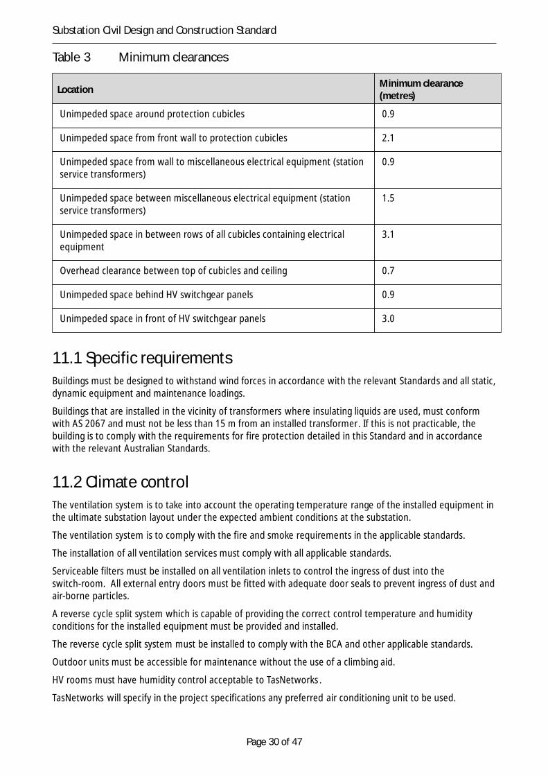
The building must maintain the minimum clearances outlined in Table 3, to ensure that accessibility andadequate space is provided around all electrical equipment. The minimum clearances must be maintained toensure that the electrical equipment can be safely and effectively operated and adjusted at all times.
Page 30 of 47
Substation Civil Design and Construction Standard
Table 3 Minimum clearances
Location Minimum clearance(metres)
Unimpeded space around protection cubicles 0.9
Unimpeded space from front wall to protection cubicles 2.1
Unimpeded space from wall to miscellaneous electrical equipment (stationservice transformers)
0.9
Unimpeded space between miscellaneous electrical equipment (stationservice transformers)
1.5
Unimpeded space in between rows of all cubicles containing electricalequipment
3.1
Overhead clearance between top of cubicles and ceiling 0.7
Unimpeded space behind HV switchgear panels 0.9
Unimpeded space in front of HV switchgear panels 3.0
11.1 Specific requirementsBuildings must be designed to withstand wind forces in accordance with the relevant Standards and all static,dynamic equipment and maintenance loadings.
Buildings that are installed in the vicinity of transformers where insulating liquids are used, must conformwith AS 2067 and must not be less than 15 m from an installed transformer. If this is not practicable, thebuilding is to comply with the requirements for fire protection detailed in this Standard and in accordancewith the relevant Australian Standards.
11.2 Climate controlThe ventilation system is to take into account the operating temperature range of the installed equipment inthe ultimate substation layout under the expected ambient conditions at the substation.
The ventilation system is to comply with the fire and smoke requirements in the applicable standards.
The installation of all ventilation services must comply with all applicable standards.
Serviceable filters must be installed on all ventilation inlets to control the ingress of dust into theswitch-room. All external entry doors must be fitted with adequate door seals to prevent ingress of dust andair-borne particles.
A reverse cycle split system which is capable of providing the correct control temperature and humidityconditions for the installed equipment must be provided and installed.
The reverse cycle split system must be installed to comply with the BCA and other applicable standards.
Outdoor units must be accessible for maintenance without the use of a climbing aid.
HV rooms must have humidity control acceptable to TasNetworks .
TasNetworks will specify in the project specifications any preferred air conditioning unit to be used.

Page 31 of 47
Substation Civil Design and Construction Standard
Penetrations in walls and ceiling must be sealed to be weatherproof.
11.3 Floor and floor levelsAll building floors must be steel reinforced concrete and must be of suitable tolerance and surface finish forthe movement, installation and maintenance of the installed equipment including control panels,communication equipment and battery banks where applicable.
Floors must have a uniform finished level throughout with a tolerance of ±0.1 mm unless otherwise specifiedby the switch board manufacturer.
Where applicable, floors for all multilevel buildings must be steel reinforced concrete with steel or concretesupport beams.
Where a false floor is installed in an existing building, approval is required by TasNetworks .
11.4 AccessBuildings must be located adjacent to a roadway or loading bay and access doors located to facilitate ease ofinstallation, operation and maintenance of equipment.
11.5 External facadeBuilding external walls must be constructed from steel reinforced concrete, masonry blocks, bricks, orpre-cast products to provide a durable, weatherproof and water resistant surface.
Brick walls must be double skin.
Masonry block walls must be double skin or single skin moisture sealed.
Masonry block or pre-cast concrete walls must have an approved textured finish on the outside.
The design and construction of the walls must comply with the appropriate standards.
11.6 Surface finishesAll surfaces must be of a suitable durable finish so as to minimise maintenance over the design life of thesubstation. Where required, surfaces must be coated or painted to meet compliance. Coatings or paintedfinishes must have a design life of 25 years.
All painted surfaces must be painted with a minimum of two coats of approved paint.
The entire exposed concrete floor must be painted with a non-slip coating to prevent concrete dustformation and to provide a uniform surface finish.
11.7 RoofingRoof structures must consist of Colorbond steel (or equivalent), installed over sisalation on a prefabricatedsteel trussed or skillion roof, in accordance with the relevant Authority’s requirements and the BCA. Skillionroofs are only to be used where height restrictions dictate.
The roofing system must be designed and installed so as to minimise maintenance over the design life of thesubstation.
No penetrations are allowed in the roofing material.
Where environmental, industrial or agricultural pollution conditions are severe, alternative materials may berequired to comply with the requirements of this clause.

Page 32 of 47
Substation Civil Design and Construction Standard
The system must be fixed and sealed to:
(a) remain intact and waterproof under the local climatic, industrial and agricultural conditions;
(b) provide adequate means of dealing with vapour pressure, condensation, corrosion and thermalmovement;
(c) support the superimposed dead, live and wind loads according to AS/NZS 1170; and
(d) ensure that all metallic parts are permanently connected to the substation earthing system.
11.1 CeilingA two-layer fire retardant plasterboard ceiling must be installed to comply with all relevant buildingstandards and comply with AS 1530.4 and the BCA for a 3 hours fire rating.
11.2 Guttering and downpipeGuttering, downpipes and fittings must be supplied, installed and extended to the stormwater drain inaccordance with the relevant standards, relevant authorities’ regulations and the BCA. Guttering anddownpipes must be external and must be UV protected uPVC.
Internal guttering on roofs is not permitted.
11.3 InsulationThe building must be insulated to AS 4859.1 as well as the provisions of the BCA to minimise fluctuatingtemperatures within.
11.4 Internal partitionsInternal partitions, if required, must be constructed with masonry blocks or precast concrete panels andmust comply with the BCA.
11.5 Doors and entrances/exitsBuildings must have at least two external entry/exit doors.
Buildings must comply with the BCA for fire exits relative to the classification of the building.
The external doors must be outward opening, self-closing doors, weather sealed and painted to match theexternal surface finish. Single metal-clad door construction is preferred.
Internal doors must comply with the BCA to retard the spread of fire within the building.
Main entry doors must be single doors 2400 mm high x 1000 mm wide. The use of alternative door sizesmust be approved by TasNetworks prior to the commencement of construction.
All external doors must be protected from the weather by either rain guards at the top of the door or aporch recess into the building.

Page 33 of 47
Substation Civil Design and Construction Standard
11.6 Lighting
11.6.1 Internal lightingAdequate lighting must be provided in all rooms, corridors, entrances, stairs and any other locations fornormal inspection, operation, testing and modification works.
The level of luminance must be adequate for testing and modification works to be carried out in any panelwithout the need for additional lighting.
The design must maximise the use of energy efficient lighting.
All switches must be illuminated with indicating light mechanisms to enable ease of identification.
Lighting must conform to BCA.
All switches must be indelibly labelled for identification.
11.6.1.1 Auxiliary DC lighting
Auxiliary DC lighting is to be installed within buildings containing High Voltage Metalclad Switchgear andprotection and control equipment.
The Auxiliary DC lighting is to provide lighting in the event of a power failure. In the event of a power failure,emergency exit lights will provide light for emergency egress as per Clause 11.14.3 of this document. TheAuxiliary DC lighting is designed to provide lighting for operational personnel to enter the building withsufficient lighting after a prolonged period (in excess of 90 minutes by which time emergency exit lightingwill be extinguished). These lights will be supplied from the 125 volt Substation Battery. Lighting must becontrolled by a spring return switch connected to a two hour timer. The timer is to have a local reset pushbutton which is to be mounted on the escutcheon of the Substation DC Distribution Board.
These lights are to be of the type LS9404LED-SR99 as per Specification sheet provided in Appendix 3.
The number and layout of these lights will be provided upon request from TasNetworks Asset Engineering orAsset Strategy team or as per Project Specification.
11.6.2 External lightingAll buildings and the substation yard must have lighting and power systems either installed or upgraded tomeet the following requirements:
(a) Exterior lighting must cover the entire substation yard area, including the property boundary fence.The minimum level of luminance for the substation yard electrical equipment is 4 lux;
(b) Outdoor lighting complying with AS 4282 Control of the obtrusive effects of outdoor lighting must beinstalled so that light spill does not disturb any neighbourhood residents;
(c) The lighting must not be mounted on lightning protection masts;
(d) All outdoor luminaries must be accessible for replacement, cleaning or repair without having to shutdown any of the substation equipment. Lighting poles 9 metres or greater must be of the type thatallows the luminaries to be lowered to the ground for maintenance purposes; and
(e) All switches must be indelibly labelled for identification.
Weatherproof lighting must be provided at all building entrances. The locations and level of luminance mustbe designed to ensure safety for personnel movement and must be not less than 4 lux.
Lighting provided for building entrances must be controlled outside the building.
External switches must be rated at IP56 as per AS 3000.
An external lighting management plan must be submitted to TasNetworks , and where applicable to the

Page 34 of 47
Substation Civil Design and Construction Standard
relevant Local Authority, for approval prior to the commencement of the external lighting infrastructure.Construction and installation of the outdoor lighting infrastructure must not commence until the design hasbeen approved in writing by TasNetworks .
All low voltage circuits must be installed in accordance with AS 3000.
11.1.1 Emergency lightingEmergency exit lighting must be installed to conform to the BCA.
11.2 Sockets and outletsSocket outlets must be suitable for the intended application and must comply with AS 3000.
All socket outlets must be indelibly labelled for identification.
The single phase general purpose socket-outlets must be provided for all the rooms in the control buildingsuitably spaces with minimum of two socket-outlets per room. The single phase must be rated for 240V,10 amp A.C. power supply.
A three phase general purpose socket-outlet 400V, 50 amp A.C. power supply must be provided in thesubstation yard at a position to be nominated by TasNetworks .
New buildings must have an approved electrical services plan.
11.3 Hand railingAll hand railing must comply with the BCA.
All hand railing needs to be earthed and must be made from galvanised steel hollow sections in accordancewith the applicable standards.
11.4 GlazingNo glazing, skylights or windows will be permitted as part of the external facade of buildings.
11.5 Indoor fire equipmentIndoor fire protection, detection and suppression equipment must be installed within the building inaccordance with the BCA, ENA DOC 018-2008 Interim guideline for the fire protection of electricitysubstations, AS 1670, AS 2941, and any other relevant Australian Standards.
The system must meet the approval of Fire Service Tasmania.
The building and equipment must be monitored with a smoke detection system. Fire detection system andsmoke control must be in accordance with AS 1670, AS 1668.1 and any other relevant Australian Standard.The fire detection system must include point type smoke detection and Very Early Smoke DetectionApparatus (VESDA) with ionisation, photo-optical or similar detector. The system must provide electricalsignals back to the Supervisory Control and Data Acquisition (SCADA) system.
Fire indicator panel must be provided in the proximity of the main entrance.
Fire panels must be of the type ‘Vigilant MX4428 or F3200’.
The ducting, ventilation and cabling systems must be designed to minimise transfer of fire throughout thesubstation.
Fire suppression equipment must incorporate, as a minimum:

Page 35 of 47
Substation Civil Design and Construction Standard
(a) Fire hydrants and/or hose reels to AS 2419.1 and AS 2441;
(b) Portable fire extinguishers in accordance with AS 2444; and
(c) Fire protection with regard to fire resistance of walls, ceilings, doors, etc and layout requirementsmust comply with the requirements of the applicable standards and the BCA.
11.1 Bolts and nuts for structuresThe following requirements are applicable for structures:
(a) Bolts, nuts and accessories must be corrosion free with minimum maintenance requirements for thedesign life of the substation;
(b) Bolts, nuts and accessories must have a tensile strength fit for the purpose;
(c) As a minimum requirement, hot dip galvanized steel bolts and nuts must be used;
(d) Mild steel bolts, nuts and washers must conform to AS 1111, AS 1252 and must be hot dip galvanizedto AS 1214;
(e) Bolts used on steel lattice constructions must be to AS 1559 and must be hot dip galvanized to AS 1214;
(f) In order to maintain contact of joint pressure, flat washers must be provided under the heads of boltsand under nuts. Suitable means, e.g. locking nuts or plates, belleville type washers or helical springlock washers, must be used to secure the fixing firmly; and
(g) Distortion of the metal part or enlargement of the bolt hole for correction of mismatched holes willnot be permitted.
11.1 Repairs to galvanized surfacesThe Contractor must repair galvanized surfaces in the following sequence:
1. Wire brush to ensure all loose and flaking materials are removed;
2. Apply two coats of cold galvanizing paint by brush;
3. Allowing drying between coats; and
4. Apply a silver paint by brush which when dry provides the appearance of a galvanised finish.
The Contractor must use Galmet Cold Galvanising paint and Galmet Duragal Silver paint unless otherwiseapproved by TasNetworks prior to use.
The Contractor must ensure that galvanizing repair paints are applied in accordance with the manufacturer’srecommendations.
5 Transformers
5.1 Transformer plinthsTransformers must be supported on a single monolithic homogeneous concrete plinth raised 50 mm fromthe top of the surrounding bund wall and must be at a level such that if the bund should fill with water or oilthen it will not lie against the transformer.
The plinths must be designed to resist all dead, live and wind forces on the supported equipment inaccordance with AS 3600.

Page 36 of 47
Substation Civil Design and Construction Standard
Where it is proposed to use existing transformer plinths, the design of the existing plinths must be checkedfor the loadings of the new equipment. The size of the existing plinths must be suitable for the equipment tobe installed thereon, including jacking points, and must comply with this Standard.
Departure from design surfaces must not exceed 5 mm or 1 in 200 whichever is the lesser.
5.2 Firewalls
5.2.1 General requirements for firewalls
All firewalls must be provided in accordance with AS 1940.
If the separation distance as detailed in AS 2067 cannot be achieved, ie. 10m if transformer oil volume isbetween 20,001 and 45,000 litres or 15m if between 45,001 and 60,000 litres, firewalls must be installed toprovide separation between the following components:
Power transformers .
(a) as required at the free end of the outside (extreme) transformer to provide separation to buildingsand/ or structures or to assist in the containment of oil;
(b) any power transformer and nearby buildings; and
(c) any power transformer and equipment or conductor in adjacent bays where minimum separationdistance cannot be maintained.
In certain situations where the minimum separation distance between the power transformer and thecontrol building cannot be achieved TasNetworks may waive the requirement for a firewall provided that theexterior of the building adjacent to the transformer has a minimum three hour fire rating ofFRL180/180/180.
5.1.1 Design requirements for firewallsAll firewalls must comply with the following requirements:
(a) A transformer firewall must be designed and installed to separate the transformer in case of fire;
(b) Reference to location of buildings to transformers must comply with AS 1940;
(c) Where firewalls meet at a junction, the firewalls must be appropriately connected to preventmovement between the two;
(d) Firewalls must not fully enclose a transformer unless adequate provisions are made for access,ventilation and drainage;
(e) Existing firewalls may be re-used only if specifically allowed in the project specifications. Before usingexisting firewalls an assessment must be done for adequacy of the firewalls with respect to theirlocation, size, structural capacity and fire rating;
(f) The firewall and its foundation must be designed for wind loadings in accordance with AS 1170.2,general installation and maintenance loadings. While determining the wind loads, shielding fromadjacent transformers or structures must not be taken into consideration;
(g) The firewall must be made from reinforced concrete panels, which are water, UV and hot transformeroil (100°C) resistant and resilient to the in service conditions over the design life of the installation;
(h) As a substantial visual element in the substation yard, the firewall material must be uniform in textureand colour and must be accurately shaped and aligned;
(i) The firewall must have a three hour fire rating, FRL180/180/180. Note the three figures representstructural adequacy, integrity and insulation in minutes in accordance with AS 3600;

Page 37 of 47
Substation Civil Design and Construction Standard
(j) The firewall must extend 300 mm minimum above the height of any installed transformer; and
(k) The firewall must extend 600 mm minimum past each outer side perimeter of the installedtransformers and must be spaced so as to allow maintenance access with a minimum distance of 1200mm from the transformer or associated oil cooler.
6 Oil Containment systems
6.1.1 General requirements for oil containment systems
The oil containment system must consist of:
(a) drained bunds around each transformer with a drainage flame trap outlet in each;
(b) oil containment tanks;
(c) drainage system; and
(d) flame traps immediately upstream of the primary oil containment tank.
A new oil containment system must be installed as a part of the project unless otherwise stated in theproject specifications.
Where project specifications allow the use of an existing oil containment system, the existing oilcontainment system must be upgraded to comply with this Standard and the relevant Australia Standards. Areport must be submitted to TasNetworks , confirming the suitability of the existing system for use. Theexisting oil containment system when upgraded must be repaired, replaced, or augmented to comply withthe requirements of this Standard.
The oil containment system must minimise the environmental contamination and spread of a fire in theevent of an oil spill within the substation.
In the event of an oil spill, oil must be contained while allowing the passage of storm water and/or firefighting water, to pass through the system continuously.
6.1.1 Design requirements for oil containment systemsOil containment system must be designed according to AS 1940.
Discharge requirements for the oil containment system must have no visible oil and must have totalpoly-aromatic hydrocarbon content of less than 10 ppm.
The oil containment system must be designed to catch and contain spilt oil under the following conditions:
(a) an oil spill from at least 110 per cent of the total amount of oil of the largest transformer (or oil tank)within the installation;
(b) contain and limit the spread of spilt transformer oil or any other oil, which is on fire; and
(c) manage significant volume of water within the drainage system due to fire fighting or heavy rainfall(ARI of 1 in 50 year rainfall) in conjunction with an oil spill.
6.1.1 Construction requirements for oil containment systemsAll works associated with the oil containment system must be according to D04/10171 OilContainment/Stormwater Drainage Standard.

Page 38 of 47
Substation Civil Design and Construction Standard
6.1.2 Watertightness testing for oil containment systemsThe oil containment system must be watertight. Testing to AS 3735 must be performed to confirmwatertightness and to ensure compliance with environmental legislation.
6.2 Transformer bund
6.2.1 General requirements for transformer bundBunds and associated transformer concrete plinths must be constructed for all new and existingtransformers as required in the project specifications.
A separate bund must be placed around each transformer to capture any oil in the event of a transformer oilspill, and prevent migration to adjacent transformers and equipment.
Flame traps must not be self-draining.
Each bund must be designed to effectively collect and transport any spilt oil within the bund to a drainageflame trap outlet and in turn directly into the primary oil containment tank.
When using bund walls or similar construction, the bund must prevent any oil spilt within the bund enteringonto unprotected areas and/or into adjacent bund.
6.2.2 Design requirements for transformer bundAll new bunds must be designed to comply with the minimum requirements listed below. All existing bundsmust be retained or upgraded to comply with these minimum requirements:
(a) All bunds must drain to the primary oil containment tank.
(b) Bund walls must be a minimum of 300 mm in height.
(c) The minimum distance between the transformer perimeter and the top of the bund boundary (wall ordrain) must be at least half of the height difference between the bund boundary and the highest oilcontaining element of the transformer.
(d) Bund floor must have a minimum 1 per cent slope to the lowest drainage point.
(e) Bund floor slope, outlet pipe and downstream drainage pipe system must be designed to remove alloil from the bund within 15 minutes in the event that the transformer spilled all its oil instantly.
(f) Bunds must be of the open drained type.
(g) Bunds must allow for ease of inspection and maintenance over its design life.
(h) Bunds must be watertight.
(i) Major bund construction material used must be steel reinforced concrete.
(j) Joints in the bund (if any) must be sealed with oil and fire resistant sealants.
(k) Bund floor and walls must be designed to resist water loads (and installation loads from traversing thetransformer into and out of its position.
(l) A flame trap or similar device must be installed within the bund to prevent any flame entering themajority of the drainage system and the oil containment tank. The flame trap pipe work and surroundmust be constructed from fire resistant materials, linings, gaskets, sealants etc.
(m) Penetrations through the bund floor and walls (for cables and the like) must be sealed with oil and fireresistant sealants.
(n) The installation and finish of the bund floor must not allow pooling of water or oil.

Page 39 of 47
Substation Civil Design and Construction Standard
(o) Spoon drains are not to be used.
6.1.1 Requirements for transformer bund drainageDrainage pipes and access pits between the bund and the oil containment tank must comply with thefollowing minimum requirements:
(a) The drainage system leading from the bund to the oil containment tank must be steel or fibrereinforced concrete, or similar construction, and be capable of handling liquids at 100ºC.
(b) The drainage pipe must be fire and corrosion resistant.
(c) The flame trap must be fire and corrosion resistant.
(d) Access points to be of adequate size complying with AS 3996 Access covers and grates formaintenance purposes and to allow personnel access.
(e) Access points must be provided at each change in direction, grade or maximum interval of 50 m. Allgrouts used must be watertight, hot transformer oil (100°C) and fire resistant.
(f) The drainage system must be watertight.
(g) The drainage system must be on a slight uniform grade, 1 per cent or less, to prevent excessive mixingof oil and water.
6.1 Oil containment tanks
6.1.1 General requirements for oil containment tanksOil containment tanks must be provided for the containment of spilt oil and must have the following featuresas a minimum:
(a) oil and water separation capabilities;
(b) watertightness over the entire life of the installation;
(c) use an underflow outlet or an equivalent approved method;
(d) contain spilt oil within the tank, while allowing uncontaminated water to be discharged;
(e) not require any ongoing manual operation and must be passively operated; and
(f) use primary tanks to contain oil-contaminated flow directly from transformer catchment pits.
6.1.1 Design requirements for oil containment tanksThe oil containment tank system must comply with the following:
(a) The oil containment tank must be Type “puraceptor class 1” or equivalent.
(b) Primary oil retaining capacity must be at least 110 per cent of the total amount of oil in the largesttransformer (or oil tank) within the installation.
(c) The tanks must have a minimum liquid retention time of 20 minutes under the worst loadingconditions.
(d) The containment tank inspection cover must be able to be opened and managed by one person.
(e) Underground tanks must be designed to support the passage of expected substation maintenancevehicles over the tank.
(f) The tanks must be designed to resist buoyancy pressures and earth pressures with the water/oil levelin the tank ranging from full to empty.
Page 40 of 47
Substation Civil Design and Construction Standard
7 Substation yard fire protection
7.1 General requirementsUnless otherwise specified a fire protection system comprising a fire main, fire hydrants, fire boxes andassociated ancillary equipment must be designed and installed.
Existing fire mains and hydrants in the substation must be considered as redundant and replaced unlessotherwise specified in the project specifications. Where existing fire mains and hydrants are allowed to bere-used, they must be upgraded to ensure compliance with this Standard.
7.2 Design requirementsThe fire protection system must be in compliance with:
(a) the relevant applicable standards;
(b) ENA Doc 18-2008 - Interim guideline for the fire protection of electricity substations; and
(c) the BCA requirements.
8 SecurityAll works associated with substation complex must comply with the requirements of Substation IntruderDetection and Deterrence Standard R579295. All works associated with security fence and gates mustcomply with requirements of Security Fences and Gates Standard R579297.
Substation Security must comply with ENA DOC 015-2006 National Guidelines for the prevention ofunauthorised access to electricity infrastructure. In addition, all new buildings must conform to AS 3555.1Building element – Testing and rating for intruder resistance. The following minimum requirements areapplicable:
(a) Level of attack:
• Level 2 – two men using common hand tools
(b) Rating of building elements:
• Testing – create an opening of 620 cm2
• Rating – after 10 minutes the opening is greater than 620 cm2.
9 Inspection checks and testing
9.1 Inspection checks
9.1.1 Civil worksThe Inspection and Test program (ITP) must include, but not be limited to, the following inspections:
(a) Quality check of materials, sizes and fitting arrangements of all items.
(b) Check of protective surfaces and surface finish of all item.
(c) Check of mountings and connections of all items.

Page 41 of 47
Substation Civil Design and Construction Standard
(d) Survey location of all items to establish proper clearances and compliance with design documentationand Australian Standards.
(e) Check of operation of all installed services.
(f) Check of levels and trueness.
(g) Check of cover and protection to all services.
(h) Check of pipe work and connections of all services in compliance with relevant Australian Standards.
(i) Check of provision allowances for future services.
(j) Environmental conditions have been met.
9.1.1 EarthworksInspections on earthworks must include the following checks:
(a) That site is cleared of all topsoil and deleterious material.
(b) That excavation is to correct levels and that potential safety issues are considered during excavation.
(c) Locations of stockpiled material and possibility of silt erosion.
(d) Batter slopes and height of excavation benches.
(e) Compaction.
9.1.1 Roads and surfacesInspections on roads and surfaces must include the following checks:
(a) Widths, grades and cross falls of roads.
(b) Evenness and quality of roads surface.
(c) Levels of drains, connections and drainage falls.
(d) Thickness of single size aggregate surfacing in yard.
(e) Compaction.
9.1.1 Concrete and steelworkInspections on concrete and steelwork must include the following checks:
(a) Placement of reinforcement, welding and connection to earth mat.
(b) Sizes and tolerance of steelwork in compliance with AS 4100.
(c) Cracking of steel reinforced concrete.
(d) Configuration of all installed steelwork in compliance with design documentation.
(e) Earthing of steelwork and steel reinforced structures.
9.1.1 Oil containment and drainageInspections on oil containment and drainage must include the following checks:
(a) Levels and slopes of all drainage works.
(b) Finished quality of drainage system and all grouting, connections, etc.
(c) Integrity of the oil/water separator.
(d) Integrity of the flame trap.
(e) Watertightness of drainage system.

Page 42 of 47
Substation Civil Design and Construction Standard
(f) Watertightness of oil containment tank.
9.1.1 Building servicesInspections on building services must include the following checks:
(a) The connections and functions of the security system.
(b) The connections and functions of the fire detection system are in accordance with the manufacturer’sinstructions and alarms are connected to the local HMI and NOCS.
(c) The functionality of emergency lighting.
(d) General testing requirements.
9.1 Civil testing
9.1.1 RoadworksAll testing must be performed in accordance with the relevant Australian Standard, BCA, and Relevantauthorities’ requirements or as stated within this Standard.
9.1.2 MaterialsTesting of materials must be carried out in accordance with the following requirements:
(a) Select fill, sub-base and base course materials must be tested as required by DIER StandardSpecifications.
(b) Asphalt/Bitumen seal must be tested for material quality to DIER Standard Specifications.
(c) Concrete must be strength and slump tested in accordance with the requirements of AS 1012.3.1.
9.1.1 Water-main/fire-mainCommissioning and hydrostatic testing on water-main/fire-main must be in accordance with AS 2419.1.
9.1.2 SewerageCommissioning of sewerage pipe work and sewerage treatment plant must be in accordance with therelevant standards.
10Information to be provided with submissionRequirements for information to be submitted as part of the lodged submission are outlined in documentR590638.
11DeliverablesRequirements for project deliverables are outlined in document R590634.
12Hold PointsAs identified in the PDR or as otherwise specified.
Page 43 of 47
Substation Civil Design and Construction Standard
Appendix 1 – References, definitions and acronyms
A1.1 Australian Standards
Methods of testing concrete - Determination of properties related to the consistency ofconcrete - Slump test
AS1012.3.1
ISO metric hexagon bolts and screws – Produce Grade C – bolts AS 1111
Structural design AS/NZS 1170
Hot-dip galvanised coatings on threaded fasteners (ISO metric coarse thread series) AS 1214
Methods of testing soils for engineering purposes AS 1289.5
Specification and supply of concrete AS 1379
Methods for fire tests on building materials, components and structures –combustibilitytest for materials
AS 1530.4
Fire and smoke control in multi-compartment buildings AS/NZS 1668.1
Ventilation design for indoor air containment control AS/NZS 1668.2
Automatic fire detection and alarm systems AS 1670
Maintenance of fire protection systems and equipment AS 1851
The storage and handling of flammable and combustible liquids AS 1940
Substations and high voltage installations exceeding 1 kV AC. AS 2067
Emergency escape lighting and exit signs for buildings – System design, installation andoperation
AS 2293
Fire hydrant installations – system design, installation and commissioning AS 2419.1
Installation of fire hose reels AS 2441
Portable fire extinguishers and fire blankets AS 2444
Demolition of structures AS 2601
Concrete kerbs and channels (gutters) – manually or machine placed AS 2876
Fixed fire protection installations AS 2941
Wiring Rules AS 3000
National plumbing and drainage code AS 3500
Building element –Testing and rating for intruder resistance AS 3555.1
Concrete structures AS 3600
Formwork for concrete AS 3610
Design for installation of buried concrete pipes AS 3725
Concrete structures retaining liquids AS/NZS 3735
Access covers and grates AS 3996
Precast concrete pipes (pressure and non-pressure) AS 4058
Steel Structures AS 4100
Fibre reinforced concrete pipes and fittings AS 4139

Page 44 of 47
Substation Civil Design and Construction Standard
Control of the Obtrusive Effects of Outdoor Lighting AS 4282
Earth Retaining Structures AS 4678
Structural design actions – Part 1: Permanent, imposed and other actions, 2002 AS/NZS 1170.1
Structural design actions – Part 2: Wind action, 2002 AS/NZS 1170.2
Structural design actions – Part 3: Snow and ice actions, 2003 AS/NZS 1170.3
Earthquake loads AS/NZS 1170.4
High strength steel bolts with associated nuts and washers for structural engineering AS/NZS 1252
PVC pipes and fittings for storm and surface water applications AS/NZS 1254
Structural steel welding – welding of reinforcing steel AS/NZS 1554.3
Hot-dip galvanised steel bolts with associated nuts and washers for tower construction AS/NZS 1559
Steel reinforcing materials AS/NZS 4671
A1.2 National CodesNational guidelines for prevention of unauthorised access to electricity infrastructure ENA-DOC 015-2006
Building Code of Australia BCA
Sewerage Code of Australia WSA 02
Interim guidelines for the fire protection of electricity substations ENA-DOC-18-2008
A1.3 International CodesIEC Standard Degrees of protection provided by enclosures (IP code) 60529
A1.4 TasNetworks StandardsD05/10277 Environmental Noise Standard TNM-GS-809-0085
D11/52510 Environmental Impact Assessment and Approvals
D04/10168 Land Contamination Assessment and Remediation Procedure TNM-GS-809-0087
D04/10171 Oil Containment / Stormwater Drainage Standard TNM-GS-809-0090
D04/10174 Waste Management Procedure TNM-GS-809-0092
D02/755 Contractor Risk Management Plan Standard TNM-DS-809-0113
R522697 Temporary Earthing of Substation Equipment Standard
R517372 Substation Signage Standard
D05/44571 Excavation Standard TNM-GS-809-0503
R565984 AC Distribution System Standard
R522687 General Substation Requirements Standard
R579297 Security Fences and Gates Standard
R522692 Substation Lightning Protection and Earthing Standard
R579295 Substation Intruder Detection and Deterrence Standard
R590638 Substation Civil Infrastructure - Schedule
R590634 Substation Civil Infrastructure - Deliverable

Page 45 of 47
Substation Civil Design and Construction Standard
R472616 Asbestos Management and Control in the Workplace
A1.5 DIER Standard SpecificationsR21 Clearing and Grubbing March 2009
R22 Earthworks March 2009
R23 Subgrade Zone June 2004
R24 Geotextiles March 1995
R31 Open Drains and Channels June 2004
R32 Drainage: Culverts, Pipelines and Structures June 2004
R33 Drainage and Kerb Maintenance November 2010
R36 Kerb and Gutter June 2004
R40 Pavement Base and Sub-base June 2008
R40e Explanatory Notes June 2008
R50 Guide Notes for Bituminous Surfacing Specifications June 2011
R51 Sprayed Bituminous Surfacing June 2011
R61 Road Safety Barriers October 2001
R70 Landscaping February 2005
R81 Minor Concrete Structures August 2003
A1.6 Abbreviations and definitions
AC Alternating current
AHD Australian Height Datum
ARI Average recurrence interval
BCA Building Code of Australia
CBR California Bearing Ratio
DC Direct current
DIER Department of Infrastructure, Energy and Resources
DPIPWE Department of Primary Industry, Parks, Water and Environment
EIA Environmental Impact Assessment
EPA Environmental Protection Authority
ESI Electricity Supply Industry
FCR Fine crushed rock
FRC Fibre reinforced concrete
FRL Fire resistance level
GDA Geometric Datum of Australia
HV High Voltage
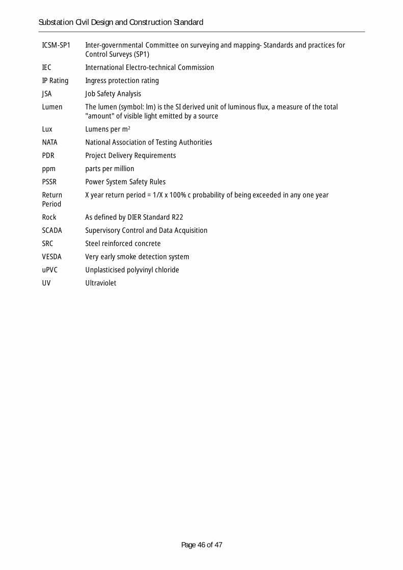
Page 46 of 47
Substation Civil Design and Construction Standard
ICSM-SP1 Inter-governmental Committee on surveying and mapping- Standards and practices forControl Surveys (SP1)
IEC International Electro-technical Commission
IP Rating Ingress protection rating
JSA Job Safety Analysis
Lumen The lumen (symbol: lm) is the SI derived unit of luminous flux, a measure of the total"amount" of visible light emitted by a source
Lux Lumens per m2
NATA National Association of Testing Authorities
PDR Project Delivery Requirements
ppm parts per million
PSSR Power System Safety Rules
ReturnPeriod
X year return period = 1/X x 100% c probability of being exceeded in any one year
Rock As defined by DIER Standard R22
SCADA Supervisory Control and Data Acquisition
SRC Steel reinforced concrete
VESDA Very early smoke detection system
uPVC Unplasticised polyvinyl chloride
UV Ultraviolet

Page 47 of 47
Substation Civil Design and Construction Standard
Appendix 2 – Project parametersThe following parameters are to be considered when preparing the relevant project outcomes and forspecific notification in any PDR or other specific project documentation.
Table 4 Project parameters
ItemNo.
ReferenceClauseNo.
Item to be Defined in Technical Specification
1 2 The design life is 50 years.Is this appropriate?
2 2.4.1 The permit(s) for the works are to be included in the PDR.Is the Contractor responsible for implementing all the conditions or are somealready delivered? Specify any special requirements.
3 2.5 All requirements of the EIA which are the responsibility of the Contactor toimplement must be listed in the PDR.
4 2.6.1 The Standard states that TasNetworks will provide ground and cadastral surveyinformation for the site if available.The data should be appended in pdf and original format.
5 2.6.3 The Standard states that the survey datum should be GDA94 and AHD. In manylocations this would be expensive to implement and a local datum to within a fewmetres of GDA94 and AHD should be sufficient. If the datum can be local datumthis must be specified.
6 2.7 If TasNetworks has any records of existing services this information must beincluded in the technical specification.
7 3.0 Existing geotechnical and soil contamination surveys must be included in the PPR.
8 4.1 The extent of existing structure removal must be defined.
9 4.2 Is there asbestos on the site?
10 5.1 The default stripping depth is 100mm. Is a different depth required?
11 5.2 The stripped top soil is to be placed on embankment batters. Is the top soil to beused for any other purpose?
12 5.2 The embankment batter treatment is up to the Contractor. Is a specific treatmentrequired? If so it must be specified.
13 6.1 The Standard does not define the extent of the various roads or if they are requiredat all.The extent must be defined.
14 6.2.16.2.26.2.4
The Standard does not seal any of the roads by default.Are any of the roads or the loading bay to be sealed?
15 6.2.3 The transformer road is specified as being constructed of concrete.Specify if this is not the case.
16 7 The default surfacing for the substation yard is a 100 mm thick dolerite or basalt.Is this to be used on this project?
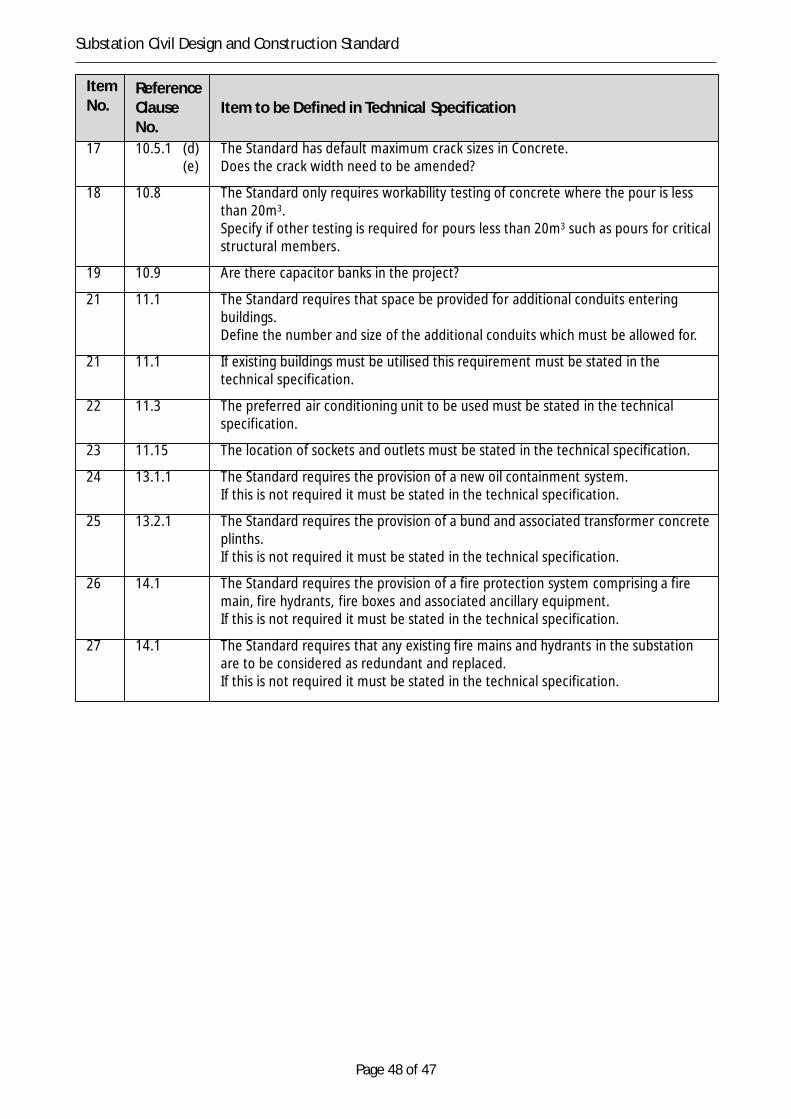
Page 48 of 47
Substation Civil Design and Construction Standard
ItemNo.
ReferenceClauseNo.
Item to be Defined in Technical Specification
17 10.5.1 (d) The Standard has default maximum crack sizes in Concrete.(e) Does the crack width need to be amended?
18 10.8 The Standard only requires workability testing of concrete where the pour is lessthan 20m3.Specify if other testing is required for pours less than 20m3 such as pours for criticalstructural members.
19 10.9 Are there capacitor banks in the project?
21 11.1 The Standard requires that space be provided for additional conduits enteringbuildings.Define the number and size of the additional conduits which must be allowed for.
21 11.1 If existing buildings must be utilised this requirement must be stated in thetechnical specification.
22 11.3 The preferred air conditioning unit to be used must be stated in the technicalspecification.
23 11.15 The location of sockets and outlets must be stated in the technical specification.
24 13.1.1 The Standard requires the provision of a new oil containment system.If this is not required it must be stated in the technical specification.
25 13.2.1 The Standard requires the provision of a bund and associated transformer concreteplinths.If this is not required it must be stated in the technical specification.
26 14.1 The Standard requires the provision of a fire protection system comprising a firemain, fire hydrants, fire boxes and associated ancillary equipment.If this is not required it must be stated in the technical specification.
27 14.1 The Standard requires that any existing fire mains and hydrants in the substationare to be considered as redundant and replaced.If this is not required it must be stated in the technical specification.

Page 49 of 47
Substation Civil Design and Construction Standard
Appendix 3 – Standard Emergency DC light