
Subsea Power Distribution.ppt - EVOLEN...Schneider Electric 11 Single-line Diagram 22kV power to 2...
18
Schneider Electric 1 Subsea Power Distribution Journées Annuelles des Hydrocarbures Octobre 2011 Jean-Luc Eschbach
Transcript of Subsea Power Distribution.ppt - EVOLEN...Schneider Electric 11 Single-line Diagram 22kV power to 2...

Schneider Electric 1
Subsea Power Distribution
Journées Annuelles des Hydrocarbures
Octobre 2011
Jean-Luc Eschbach
Schneider Electric 22
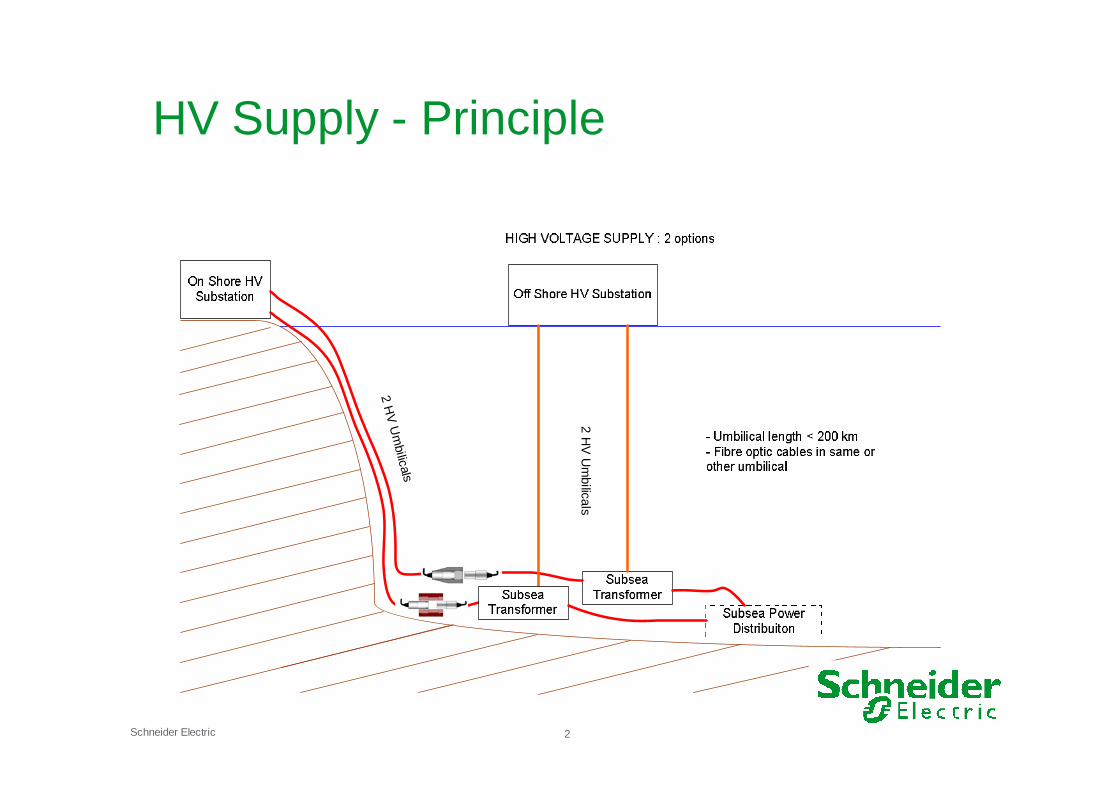
HV
Um
bilic
al s
2H
VU
mbilica
ls
HV Supply - Principle

Schneider Electric 3
Subsea Electrical Distribution & ControlArchitecture principle – Ring or Radial configuration

Schneider Electric 4
Automation architecture

Real case: Subsea projectOrmen Lange Norway

Schneider Electric 6
The entire Process on the Seabed
● As the search for oil moves into deeper waters and harsher environments production ismoving onto the seabed.
● Offshore oil and gas production has seen a significant trend in recent years: theelimination of offshore surface facilities, withthe entire production system for some of themore advanced fields located on the seabedand connected back to a terminal on theshore.
● The Ormen Lange is a good example of this approach, and is significant because it willsupply 20 per cent of the UK’s gasconsumption in coming years.
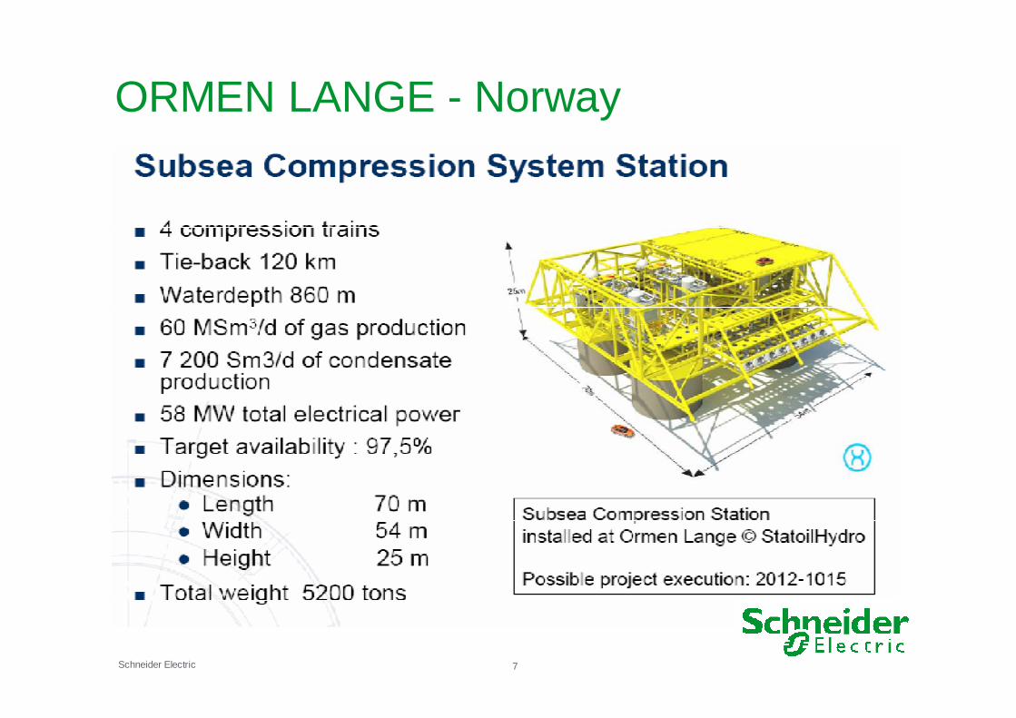
Schneider Electric 7
ORMEN LANGE - Norway

Schneider Electric 8
SE contribution to Subsea?
ORMEN LANGE - Compression Pilot
Actual SE Supply

Subsea Processing PowerDistributionSubsea Switchgear Module – Key EnablingComponent in Subsea Installations

Schneider Electric 10
Inside the Subsea Switchgear Module
Main functions•One 22 kV / 3 ~ / 1000 A Incoming frommain step-down transformer•Two 22 kV / 3 ~ / 450 A Feederssupplying VSD transformer module•Two 620 V / 3 ~ / 140 A Feederssupplying UPS module•Protection & monitoring of thesefeeders
Auxiliary functions•Insulation resistance monitoring 22KVinterconnexions•Premagnetization of VSD transformers
Overall Dimensions:Length external 17.550 mm Volume external 100 m3
Diameter external 2.750 mm Weight total 140 T
Thickness 75 mm

Schneider Electric 11
Single-line Diagram
● 22kV power to 2 process trains
● Energization via premagnetizingtransformer
● LV power to 2 UPS
● Dual feed auxiliary power back from UPS
● Identical equipment for train 1 and train 2
● Full redundant LV auxiliary power
2 identical sections

Schneider Electric 12
The Switchgear Rack
3 – Transformers for train 1
2 – LV Power, protection, control Train 1
1
2
3
4
1 – Penetrator for incoming supply
2 – Penetrator for 22kV cable to train 1
Schneider Electric 13
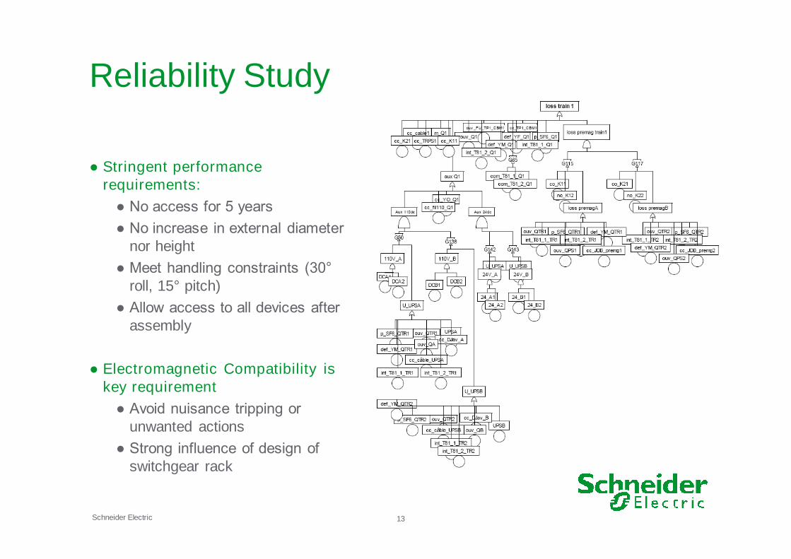
Reliability Study
● Stringent performancerequirements:
● No access for 5 years
● No increase in external diameter nor height
● Meet handling constraints (30°roll, 15° pitch)
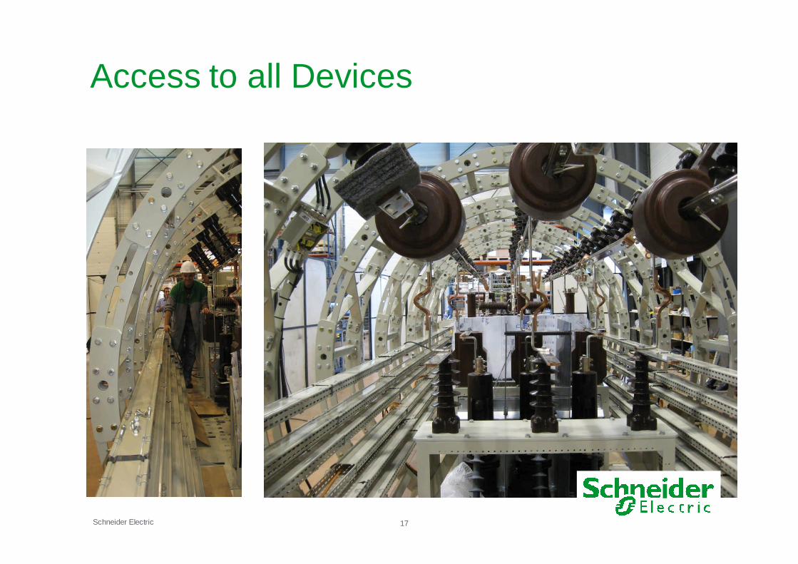
● Allow access to all devices after assembly
● Electromagnetic Compatibility iskey requirement
● Avoid nuisance tripping or unwanted actions
● Strong influence of design of switchgear rack

Schneider Electric 14
Calculations
Mechanical calculations
- Displacement, stress
Thermal calculations
- Test conditions
- Final installation conditions
- No forced ventilation required
Schneider Electric 15
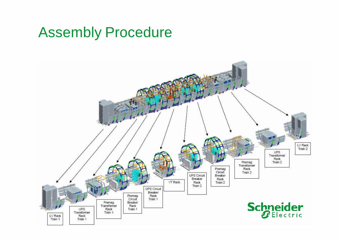
Assembly Procedure
Schneider Electric 16
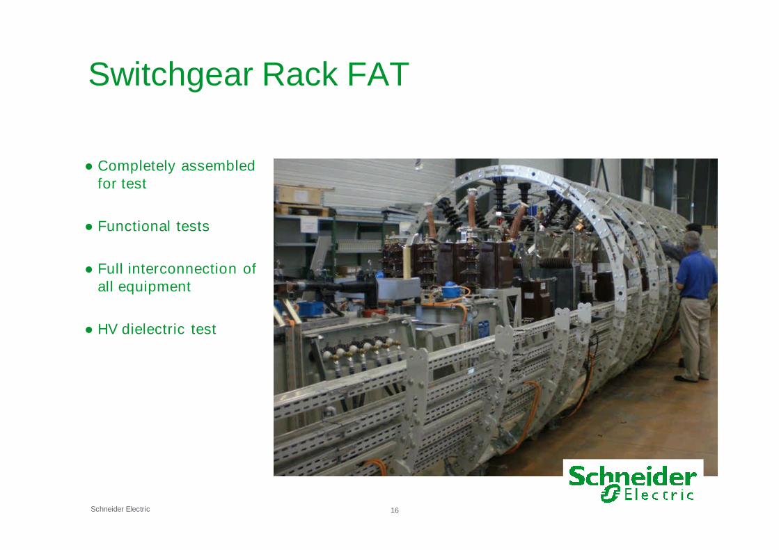
Switchgear Rack FAT
● Completely assembledfor test
● Functional tests
● Full interconnection ofall equipment
● HV dielectric test
Schneider Electric 17
Access to all Devices

Schneider Electric 18
ConclusionSystem Design
● Complete system from supply to loads must be looked for:
● protection system design (fault location and isolation)
● control of voltage at loads under steady state & transient conditions
● harmonic resonance
● installation and connection constraints
● Results of system design are inputs for equipment design
● maximum steady state & transient voltage operating conditions
● worst case scenarios for thermal & mechanical calculations
● location and types of connectors, penetrators, ROV access points
Qualification of components
● Basic philosophy - leave nothing to chance
● Every type of component selected down to the last nut and bolt
● Shop drawings with all details provided for all mechanical parts
● Assembly drawings:
● include all components to be used
● provide testing procedures used during fabrication
● Components selection based on similar applications such as military
● Type testing of any components designed specifically