Privacy preserving data mining – Introduction and randomization
SUBSEA MINING – MAJOR CHALLENGES
Dr. Ir. Sritama Sarkar
Saipem UK

CONTENTS
Seafloor Minerals Major Challenges Potential Subsea Miners Subsea Cutting Production and Power Subsea Cutting Forces, Weight and Stability Gathering Challenges Environmental Impact Transport Challenges Locomotion Challenges Launch and Recovery Challenges
2

SEAFLOOR MINERALS 3

4
Offshore Diamonds
Polymetallic Nodules
•Established industry •Maximum water depth 400m •Placer pockets in overburden (sand) overlaying clay/ bedrock
•Extensive R&D since 1970s •Ni, Cu and Co •Water depth 5000m to 6000m •Abyssal plains

5
Methane Hydrates
Cobalt Crusts
•Exploration •Water depth 500m to 2000m •Soft sediments in Arctic environment •Slope and rise sediments in continental margin
•Research •Water depth 400m to 4000m •Volcanic island arcs/ Volcanic sea-mounds – as very thin crusts

6
Seafloor Massive Sulphide (SMS) Deposits
•Exploration and planned commercial exploitation •Cu-Zn-Ag-Au` •Water Depth 1500m to 5000m • Very hot hydrothermal fluids, slightly acidic • Edges of tectonic plates

MAJOR CHALLENGES 7

8
SUBSEA MINING PROCESSES
Gathering (Hydraulic)
Transport (Hydraulic)
Cutting
Mechanical Cutting
Hydraulic Cutting
Locomotion
9
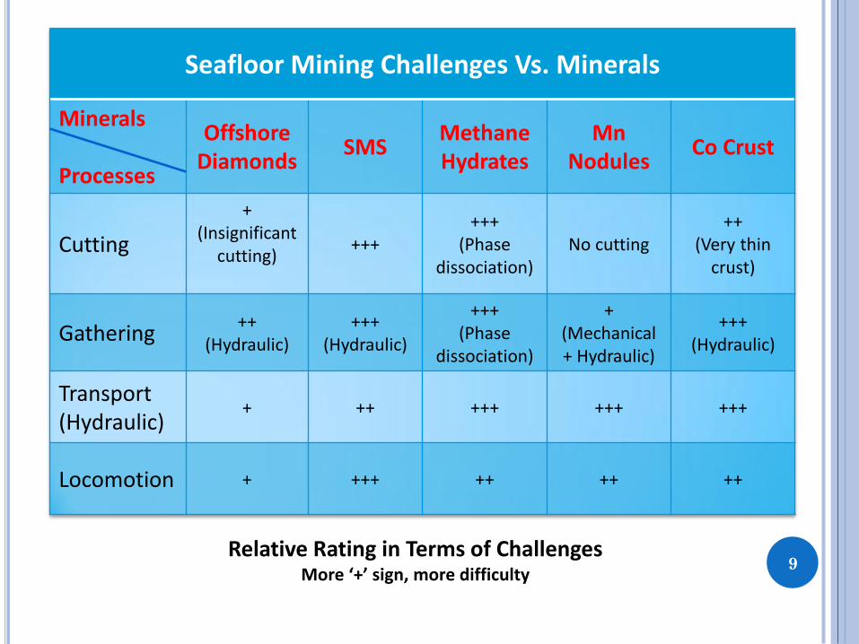
Seafloor Mining Challenges Vs. Minerals
Minerals Processes
Offshore Diamonds
SMS Methane Hydrates
Mn Nodules
Co Crust
Cutting
+ (Insignificant
cutting)
+++ +++
(Phase dissociation)
No cutting ++
(Very thin crust)
Gathering ++
(Hydraulic) +++
(Hydraulic)
+++ (Phase
dissociation)
+ (Mechanical + Hydraulic)
+++ (Hydraulic)
Transport (Hydraulic)
+ ++ +++ +++ +++
Locomotion + +++ ++ ++ ++
Relative Rating in Terms of Challenges More ‘+’ sign, more difficulty

POTENTIAL MINERS 10

11
POTENTIAL CUTTERS: DREDGING INDUSTRY
Dredge cutter And Dredge pick
Cutter Suction Dredger
Trailing Suction Hopper Dredger
Drag Head
Courtesy: Van Oord, Vosta LMG

12
POTENTIAL CUTTERS: DREDGING INDUSTRY
Courtesy: EEM (P) Ltd., India
• Surgical cutting, resulting in less environmental impact, Ref. Sarkar, M.K. 2012 • Possibly suitable for Cobalt Crust (Thin)
Transverse Cutter: Rotavator

13
POTENTIAL CUTTERS: LAND MINING
Road header Radial pick
Point attack pick
Continuous Miner
Courtesy: Sandvik

14
POTENTIAL CUTTERS: LAND MINING
Road Miner
Surface Miner
Courtesy: Trencor and Wirtgen
Position of drum cutter important for cutting force and stability of miner.

15
SUBSEA MINER CONCEPTS
Gathering Machine
Courtesy: IHC
Courtesy: Aker
Mining the Seafloor with Robots Ref.: www.iaarc.org/news/a_news_2012_09_11.pdf
Bulk Miner
Preparatory Machine

CUTTING PRODUCTION AND POWER
16

17
Average production = f(External factors, Manageable factors) Instantaneous production = f(Average production, Uncontrollable factors)
CUTTING PRODUCTION

CUTTING PRODUCTION (SOLIDS)
18
Based on Nautilus Minerals estimated Annual Production = 1.8Million Tonnes (dry) from
Solwara 1
Ref: http://www.nautilusminerals.com/s/Home.asp
NAT005_Solwara_1_Offshore_Production_System_Definition_and_Cost_Study_Rev_3_21_June20
10
CUTTING PRODUCTION(SOLIDS) – CASE STUDY
Production Envelope - Example

CUTTER DRIVE POWER
Dynamic factor(DF): Ratio between peak and average cutting force For hydraulic drives: Hydraulic efficiency and gear box efficiency Hydrodynamic efficiency: Hydrodynamic drag of rotating cutter Recirculation efficiency: Regrinding of excavated material
19
CUTTER DRIVE POWER
Instantaneous Production = Specific Energy =

20
SPECIFIC ENERGY (LAND): EVAN’S MODEL

Specific Energy (Subsea) = f(In-situ UCS, Hyperbaric Factor)
Disturbed sample: Decompression effect on UCS
Hyperbaric factor = f(Rock properties, Cutting parameters, Cutting tool geometry and lacing)
21
ROCK FAILURE: SUBSEA CONDITIONS

22
CUTTER DRIVE POWER: GENERIC EXAMPLE
Calculation Approach
Required Ins. Solids Production
(m^3/hr)
Cutter Drive Power for Sp. En. =
10kJ/m^3
Cutter Drive Power for Sp. En. =
20kJ/m^3
Optimistic Approach
Min Max
130 200
900 1500
1900 3000
Conservative Approach
Min Max
135 220
1000 1600
2000 3300
Cutter drive power determines weight of the subsea miner
If specific energy increases challenges in subsea power technologies (voltage levels etc.)need to be addressed
Design of Launch and Recovery System is dependent on weight of the subsea miner
Option for multiple subsea miner

CUTTING FORCES, WEIGHT AND STABILITY
23

24 F_h: Horizontal Force, F_v: Vertical Force, F_a: Axial Force
CUTTING FORCE: DREDGE CUTTER
25
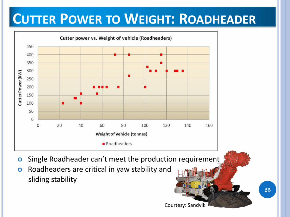
Single Roadheader can’t meet the production requirement
Roadheaders are critical in yaw stability and
sliding stability
CUTTER POWER TO WEIGHT: ROADHEADER
Courtesy: Sandvik

26
Approximate Cutter Drive Power: Miner Weight Ratios (Air) Continuous Miner = 4:1 Surface Miner = 6:1
CUTTER POWER TO WEIGHT: DRUM CUTTERS

27
RESULTS – DRUM CUTTERS
Courtesy: Sandvik
Largest subsea vehicles: Rock Trencher RT1 (Deep Ocean)
Weight = 200Te (Air) Total power = 2.3MW Total cutter power in 3 chain cutters = 250kW, 2*400kW Operating depth = 500m
Pipeline Plough PL3 (Saipem) Weight = 240Te (Air)
Machine WeightPeak Force (Hor.
And Vert.)
(Te) (Te)
240 to 400 20 to 35
480 to 820 40 to 70
Machine WeightPeak Force (Hor.
And Vert.)
(Te) (Te)
160 to 270 20 to 35
300 to 550 40 to 70
10MJ/m^3
Cutter Drive Power
(kW)
900 to 1600
Continuous Miner (Cutter Power : Weight = 4:1)
20MJ/m^3 1900 to 3300
Sp. Energy
Sp. Energy
Surface Miner (Cutter Power : Weight = 6:1)
Cutter Drive Power
(kW)
10MJ/m^3 900 to 1600
20MJ/m^3 1900 to 3300

Compressive strength and specific energy of cutting very important
Laboratory tests
In-situ tests
Uncertainty in cutter drive power estimation reduced by accurate determination of ore properties
Cutter drive power and cutter mounting position determines weight of the subsea miner
Stability of subsea miner controlled by cutting forces generated and machine design parameters
28
SUMMARY – CUTTING

GATHERING CHALLENGES
29

The rock mass properties and cutting methodology determines particle size distribution of excavated ore
The suction velocity should be sufficient to gather as much as possible of the excavated ore
Environmental impact should be minimum
Suction velocity should match the riser transport velocity – hence impacts the design of riser pump(s) and diameter of riser
30
GATHERING CHALLENGES

ENVIRONMENTAL IMPACT
31

Habitat assessment
Plume generation due to cutting and gathering devices – impact on species existing in mine area
Noise generation
32
ENVIRONMENTAL SENSITIVITY
33
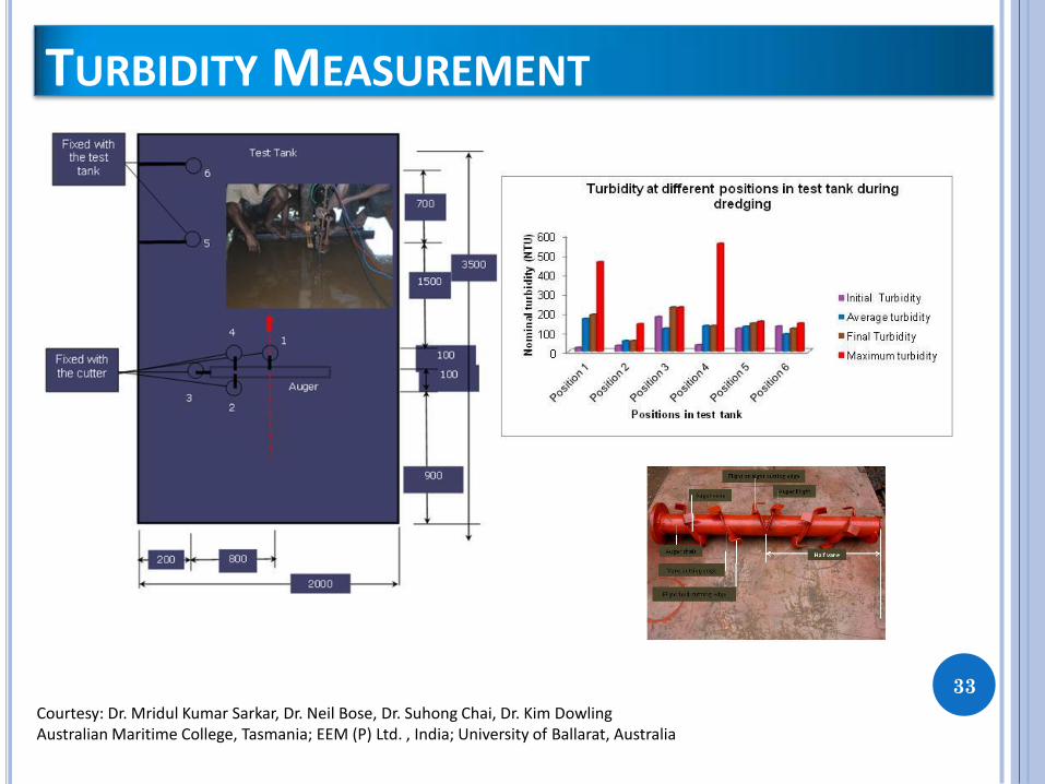
TURBIDITY MEASUREMENT
Courtesy: Dr. Mridul Kumar Sarkar, Dr. Neil Bose, Dr. Suhong Chai, Dr. Kim Dowling Australian Maritime College, Tasmania; EEM (P) Ltd. , India; University of Ballarat, Australia

TRANSPORTATION CHALLENGES
34

Involves transportation of the excavated ore as a slurry from the seabed to the surface support vessel
Research work – ongoing on vertical transport of slurry by various universities and research institutes
Variation in the slurry density will change the catenary shape of the riser (if flexible riser used)
With the variation in the slurry density additional forces will be transferred to the connection point with the subsea miner
Riser wear needs to be investigated
35
TRANSPORTATION CHALLENGES

LOCOMOTION CHALLENGES
36

Topography of the terrain
Slope of the terrain
Rock – Reduced friction of wet rock, e.g. SMS and Cobalt crusts
Soft sediments – Bearing Capacity, e.g. Methane hydrates, Polymetallic nodules
Proper assessment of cutting forces necessary for sliding stability assessment
Additional devices to balance cutting forces when friction is low
37
LOCOMOTION CHALLENGES

38
OTHER LOCOMOTION DEVICES
Cutter module
Suction mouth
Dipper Ladder boom
Eductor pump
Rotating yoke
Leg
Foot
Ref: Dr. S Sarkar, Dr. N. Bose, Memorial University of Newfoundland, Canada and
Dr. M.K.Sarkar, EEM (P) Ltd. India 2002-2007
Ref: Dr. M.K. Sarkar, EEM (P) Ltd. , India Dr. N. Bose, Australian Maritime College, Tasmania, 2008- 2012
Courtsey: IHC Deep Sea Mining

39
LAUNCH AND RECOVERY SYSTEM
Support Vessel
Umbilical
Riser System
Subsea Miner Lifting Wire
Courtesy: Saipem, Wellstream (GE), Seatools, Certex

40
Dynamic subsea component – since the subsea miner is continuously moving
The subsea miner needs to be recovered frequently for scheduled/ unscheduled maintenance
Static subsea system
Once installed the subsea structure is not recovered
Flowlines
Risers
Jumpers
Transfer
Lines
LARS Requirement: Oil and Gas
LARS Requirement: Subsea
Mining
Courtesy: Wellstream and Nautilus Minerals

Support vessel – DP operated or moored
Weight of subsea miner and DAF will control design of LARS
Management of the riser during operation and movement of the support vessel in the mine
Shape of riser determined by environmental load, slurry density and movement of subsea miner – pipeline integrity
Accurate estimation of weather downtime
41
LAUNCH AND RECOVERY SYSTEM:CRITICALITIES
Wave, Current

Design of suitable devices for in-situ determination or ore properties
Wear estimation of cutter tooth and riser system
Robotic change of cutter tooth subsea
Riser integrity monitoring during subsea mining operation
42
FOOD FOR THOUGHT
Wave, Current

QUESTIONS ???
43