Subsea Capping Stack Technology Requirements
188
Subsea Capping Stack Technology Requirements Prepared for: BSEE Doc Ref: 100124.01-DG-RPT-0004 Rev: 0 Date: February 2016 Final Report
Transcript of Subsea Capping Stack Technology Requirements

Subsea Capping Stack Technology
Requirements
Prepared for: BSEE
Doc Ref: 100124.01-DG-RPT-0004
Rev: 0
Date: February 2016
Final Report


Subsea Capping Stack Technology Requirements
Final Report
100124.01-DG-RPT-0004 | Rev 0 | February 2016
Page 3 of 188
Limitations of the Report
The scope of this report is limited to the matters explicitly covered and is prepared for the
sole benefit of the Bureau of Safety and Environmental Enforcement (BSEE). In
preparing the report, Wood Group Kenny (WGK) relied on information provided by BSEE
and third parties. WGK made no independent investigation as to the accuracy or
completeness of such information and assumed that such information was accurate
and complete.
All recommendations, findings, and conclusions stated in this report are based on facts
and circumstances as they existed at the time this report was prepared. A change in any
fact or circumstance on which this report is based may adversely affect the
recommendations, findings, and conclusions expressed in this report.

Subsea Capping Stack Technology Requirements
Final Report
100124.01-DG-RPT-0004 | Rev 0 | February 2016
Page 4 of 188
Executive Summary
Since 2010, the industry has made great strides in increasing the capabilities for subsea well
control response based on learnings from the Macondo incident. This study provides a detailed
analysis of the subsea capping stack availability, storage locations, and technical capabilities.
This study also reviews the regulations and standards and a draft Code of Federal Regulations
(CFRs) and a Potential Incident of Noncompliance (PINC) list for subsea capping stacks has
been developed.
The subsea capping stack is part of the Source Control and Containment Equipment (SCCE),
along with the cap and flow system, the containment dome, and other subsea and surface
devices, equipment, and vessels. The collective purpose of SCCE is to control a spill source
and stop the flow of fluids into the environment. This study, which is specific to subsea capping
stacks, does not consider other SCCE.
Literature Review and Industry Surveys
Wood Group Kenny (WGK) has conducted a detailed literature review to evaluate available U.S.
regulations for source control and containment. It was determined that current U.S. regulations
include no information related to SCCE. The Bureau of Safety and Environmental Enforcement
(BSEE) issued Notice to Lessees and Operators (NTL) 2010-N10, which required Operators to
demonstrate that they have access to capping and containment equipment to receive approval
for the Application for Permit to Drill (APD). In April 2015, the BSEE published a Proposed Rule
for well control that would consolidate the current regulations and NTLs. As part of the Proposed
Rule, the BSEE provided a separate section for source control and containment.
In February 2015, the Department of the Interior (DOI), acting through the BSEE and the
Bureau of Ocean Energy Management (BOEM), proposed regulations on requirements for
exploratory drilling in the Arctic Outer Continental Shelf (OCS). This proposed Arctic regulation
requires access to SCCE with a subsea capping stack positioned to arrive at a well within 24
hours after a loss of well control, and a cap and flow system and a containment dome
positioned to arrive at the well within 7 days after a loss of well control. Currently, there are no
active U.S. regulations or inspection criteria guidelines for subsea capping stacks.
American Petroleum Institute Recommended Practice (API RP) 17W provides guidelines for the
design, manufacture, use, preservation, transportation, and maintenance procedures of subsea
capping stacks. The development and delivery of subsea capping stacks began immediately
following the Macondo incident in 2010, prior to the issuance of API RP 17W. The design of
these systems was based on the existing subsea equipment (for example, Blowout Preventer
[BOP] rams, valves, and chokes), for which industry standards were already established. The
strategy for the design of subsea capping stacks was employed to allow for rapid delivery to
industry, based on conventional components, field-proven track records, accepted reliability,

Subsea Capping Stack Technology Requirements
Final Report
100124.01-DG-RPT-0004 | Rev 0 | February 2016
Page 5 of 188
established technical knowledge base, and availability of spare parts. In addition, an objective of
this strategy was to avoid the high costs and long lead times generally associated with the
development of new safety equipment technology by shortening the process typically
associated with its conception, design, fabrication, testing, and certification.
Subsea Capping Stack Availability
The consortiums and organizations that own subsea capping stacks are listed in the
following table.
Name Type No. of Subsea
Capping Stacks Staging Location Region Served
MWCC Consortium 3 Ingleside, TX U.S. Gulf of Mexico
HWCG Consortium 2 One in Houston, TX and
another in Ingleside, TX U.S. Gulf of Mexico
OSPRAG Consortium 1 Aberdeen, Scotland U.K. Continental Shelf
OSRL Consortium 4
One at each location:
Brazil, Norway, Singapore,
and South Africa
Global (except U.S. waters)
WellCONTAINED Organization 2 One in Aberdeen, Scotland
and another in Singapore
Global (inclusive of U.S.
waters)
Shell Operator 3
One in Alaska; others in
Aberdeen, Scotland, and
Singapore
Global (Shell operations
only)
BP Operator 2 One in Houston and
another in Angola
Houston stack (Global BP
operations)
Angola stack (BP
operations only in Angolan
waters)
For the U.S. Gulf of Mexico (GOM), it is mandatory for Operators conducting subsea drilling
operations to demonstrate access to a subsea capping stack and the necessary expertise and
assets to mobilize and install the stack offshore. Five subsea capping stacks to facilitate
compliance with this requirement are staged within the Gulf Coast region. Two consortiums and
one organization support the U.S. GOM. The Marine Well Containment Company (MWCC) is a
consortium that provides access to three subsea capping stacks, and HWCG LLC is a
consortium that provides access to two subsea capping stacks. In addition, WellCONTAINED
Subsea Capping Stack Technology Requirements
Final Report
100124.01-DG-RPT-0004 | Rev 0 | February 2016
Page 6 of 188
organization maintains two subsea capping stacks outside of the U.S. These stacks can be
mobilized to U.S. GOM if needed. Currently, WellCONTAINED does not support Operators in
obtaining permits to drill in the U.S. GOM region.
For the U.K. Continental Shelf (UKCS), three subsea capping stacks are staged within the
region. The Oil Spill Prevention and Response Advisory Group (OSPRAG) is a consortium that
has one subsea capping stack staged in Aberdeen, U.K. The WellCONTAINED organization
has one subsea capping stack staged in the U.K., which is available for global use. The Oil Spill
Response Limited (OSRL) consortium has one subsea capping stack staged in Norway that is
available for global use.
Outside of the U.S. and U.K. regions, excluding Operator-owned stacks, the industry has
access to six subsea capping stack systems that are made available through the OSRL
consortium and the WellCONTAINED organization. The OSRL consortium has a total of four
subsea capping stacks that are available for use outside of U.S. waters; they are staged in
Norway, Brazil, Singapore and South Africa. The WellCONTAINED organization has two
subsea capping stacks available for use globally; they are staged in the U.K. and Singapore.
In summary, the U.S. and U.K. are the only regions with dedicated consortiums (e.g., MWCC,
HWCG, and OSRPAG) to support subsea capping stack response. However, there is subsea
capping stack access for all regions of the world through the OSRL consortium and the
WellCONTAINED organization. The caveat to this statement is that most of the countries do not
have regional access to a subsea capping stack, and they are dependent on the consortium or
the organization-owned capping solutions staged at varying strategic locations around the
world. It can be surmised that these regions and countries will likely have longer response times
because of the length of time associated with marine transport of the subsea capping stack from
their storage locations to the incident sites.
Recommended CFR and PINC List
WGK has worked with the Well Containment Consortiums (MWCC, HWCG LLC, and OSRL)
and a manufacturing company (Trendsetter Engineering) to draft regulations for subsea capping
stacks based on global learnings and experience with subsea capping stacks. WGK
recommends that the drafted Code of Federal Regulations (CFR) be incorporated as part of 30
CFR 250 Subpart D.
WGK also drafted the PINC List for subsea capping stacks in accordance with the format
included in the National PINC Guideline List. WGK participated in a workshop with the Well
Containment Consortiums to review the draft PINC List and to get their feedback. WGK
recommends that the PINC List be appended to the current Drilling PINCs. BSEE personnel can
use this PINC List for inspection in the field and at onshore support bases.

Subsea Capping Stack Technology Requirements
Final Report
100124.01-DG-RPT-0004 | Rev 0 | February 2016
Page 7 of 188
The subsea capping stack CFR and the PINC List are only recommendations to BSEE: BSEE
may modify and use them in the future.
Recommendations:
Evaluate subsea capping stack components that can accommodate weight savings. This
could involve using gate valves instead of BOP rams for smaller bore sizes. The gate
valves can provide the same pressure rating as BOP rams. The benefits associated with
the use of gate valves include improved sealing reliability (metal-metal sealing surface),
reduction in weight, and simplified operation, thereby avoiding the need for Subsea
Accumulator Module (SAM) units.
Because of the geographic distances between subsea capping stack storage locations and
potential incident sites, it is recommended that a specific subsea capping stack should be
identified prior to the commencement of operations within each deep water drilling region
and the associated mobilization planning that is conducted to determine the estimated
response time. This process would allow for the assessment of an estimated response
time to ensure that it is acceptable as well as to identify areas for efficiency improvement
related to deployment and installation
Develop subsea capping stacks for High Pressure High Temperature (HPHT) conditions.
The consortium owners should consider procuring new HPHT subsea capping stacks or
improving the capabilities of the existing ones, depending on the members’ planned wells
to which the consortium may need to respond. Shell has contracted Trendsetter to deliver
a 400°F subsea capping stack in 2016, and MWCC has contracted Trendsetter to deliver a
20,000 psi subsea capping stack by 2017.
Review other parts of SCCE (such as the containment system1, debris removal, and
dispersant equipment). Currently, there are no minimum requirements for the containment
system and no consistency on what defines a containment system. There are different
technologies and levels of containment system (interim versus long-term), depending on
the capabilities. It must be noted that the absence of ‘minimum requirements’ or a
definition of a containment system has allowed development (in the U.S. GOM at least) of
two different, robust solutions. In addition, the interfaces between subsea capping stacks
and containment systems have not been standardized; this could lead to delays in
deployment and recovery operations should an incident occur.
Although BSEE currently uses terminology such as ‘Cap,’ ‘Cap and Flow,’ and ‘Source
Control and Containment Equipment,’ it is highly recommended that this terminology be
assessed and reviewed against terminology which is being standardized internationally.
1 A containment system includes any system or component downstream of the subsea capping stack that
directs flow.

Subsea Capping Stack Technology Requirements
Final Report
100124.01-DG-RPT-0004 | Rev 0 | February 2016
Page 8 of 188
Some examples of major discrepancies include the U.S. term ‘Cap and Contain’ (which
means installation and shut-in with a subsea capping stack), while the term ‘Capping’
means the same thing internationally. In the U.S., the term ‘Cap and Flow’ implies that a
capping stack has been installed, but the well is being flowed to a surface vessel;
internationally, the term ‘Containment’ has the same meaning.

Subsea Capping Stack Technology Requirements
Final Report
100124.01-DG-RPT-0004 | Rev 0 | February 2016
Page 9 of 188
Revision History (Optional)
Revision Date Comments
A
B
C
0
11 Nov 2015
30 Nov 2015
30 Dec 2015
09 Feb 2016
Issued for Internal Review
Issued for Client Review
Issued for Client Review with Comments Incorporated
Issued for Use
HOLDS
No. Section Comment
Signatory Legend
Revision Role Comments
0 Prepared
Checked
Approved
Bhaskar Tulimilli (BT)
Jorge Alba (JA)
Eddie Mouret (EM)

Subsea Capping Stack Technology Requirements
Final Report
100124.01-DG-RPT-0004 | Rev 0 | February 2016
Page 10 of 188
Table of Contents
1.0 Introduction...................................................................................................................... 20
1.1 General ................................................................................................................................... 20
1.2 Background ............................................................................................................................ 20
1.3 Report Objectives ................................................................................................................... 21
1.4 Abbreviations .......................................................................................................................... 22
2.0 Source Control and Containment (or Well Containment) ............................................. 26
2.1 Introduction ............................................................................................................................. 26
2.2 Post-Blowout Remediation ..................................................................................................... 26
2.3 Subsea Capping Stacks ......................................................................................................... 27
2.3.1 Subsea Capping Stack Categories .................................................................................... 28
2.3.2 Major Components of a Subsea Capping Stack ................................................................. 30
2.4 Well Containment Response Work Flow ................................................................................ 37
2.4.1 General .............................................................................................................................. 37
2.4.2 Site Survey and Initial Assessment .................................................................................... 39
2.4.3 Debris Removal ................................................................................................................. 39
2.4.4 Subsea Dispersant Application .......................................................................................... 40
2.4.5 Capping ............................................................................................................................. 41
2.4.6 Capture and Collection ...................................................................................................... 42
2.4.7 Relief Well ......................................................................................................................... 43
3.0 Available Subsea Capping Stacks and their Technical Capabilities ............................ 44
3.1 Introduction ............................................................................................................................. 44
3.2 Subsea Capping Stacks Consortiums and Organizations ...................................................... 44
3.2.1 Marine Well Containment Company .................................................................................. 46
3.2.2 HWCG LLC ....................................................................................................................... 51
3.2.3 Oil Spill Prevention and Response Advisory Group ........................................................... 55
3.2.4 Subsea Well Response Project/Oil Spill Response Limited ............................................... 57
3.2.5 WellCONTAINED .............................................................................................................. 64
3.2.6 Shell .................................................................................................................................. 69
3.2.7 BP ..................................................................................................................................... 73
4.0 Subsea Capping Stacks Gap Analysis ........................................................................... 78

Subsea Capping Stack Technology Requirements
Final Report
100124.01-DG-RPT-0004 | Rev 0 | February 2016
Page 11 of 188
5.0 Specifications, Standards, and Recommended Practices Applicable to Subsea Capping Stacks ................................................................................................................ 82
5.1 Introduction ............................................................................................................................. 82
5.2 API Specifications Relevant to Subsea Capping Stacks ........................................................ 82
5.2.1 API 16D – Specification for Control Systems for Drilling Well Control Equipment and Control Systems for Diverter Equipment ............................................................................ 82
5.2.2 API 6A – Specification for Wellhead and Christmas Tree Equipment/ISO 10423 ............... 83
5.2.3 API 16A – Specification for Drill-through Equipment/ISO 13533 ........................................ 83
5.2.4 API 17D – Design and Operation of Subsea Production Systems – Subsea Wellhead and Tree Equipment .......................................................................................................... 84
5.2.5 API 6AV1 – Specification for Validation of Wellhead Surface Safety Valves and Underwater Safety Valves for Offshore Service ................................................................. 84
5.3 API Standard 53 – Blowout Prevention Equipment Systems for Drilling Wells ...................... 84
5.4 API Recommended Practices Relevant to Subsea Capping Stacks ...................................... 85
5.4.1 API 17W – Recommended Practice for Subsea Capping Stacks ....................................... 85
5.4.2 API 17H – Recommended Practice for Remotely Operated Vehicle (ROV) Interfaces on Subsea Production Systems .............................................................................................. 86
5.4.3 API 17G – Recommended Practice for Completion/Workover Risers ................................ 86
6.0 U.S and Global Regulations Available for Subsea Capping Stacks ............................. 88
6.1 Introduction ............................................................................................................................. 88
6.2 International Regulators Capping Solutions ........................................................................... 88
6.2.1 Australian Capping Solution ............................................................................................... 88
6.2.2 Canadian Capping Technology .......................................................................................... 89
6.2.3 Norway Capping Solution .................................................................................................. 90
6.2.4 U.K. Capping Solution ....................................................................................................... 91
6.2.5 Brazil Capping Solution ..................................................................................................... 91
6.2.6 New Zealand Capping Solution ......................................................................................... 91
6.2.7 Denmark, Mexico, and the Netherlands Capping Solution ................................................. 91
6.3 Current U.S. Regulations – 30 CFR 250 ................................................................................ 92
6.4 Current Notice to Lessees and Operators Related to Well Control ........................................ 95
6.4.1 NTL 2010-N06 ................................................................................................................... 95
6.4.2 NTL 2010-N10 ................................................................................................................... 96
6.5 Regulation in Development..................................................................................................... 97
6.5.1 Proposed Arctic Drilling Rule ............................................................................................. 97
6.5.2 Proposed Well Control Rule ............................................................................................... 98

Subsea Capping Stack Technology Requirements
Final Report
100124.01-DG-RPT-0004 | Rev 0 | February 2016
Page 12 of 188
7.0 Subsea Capping Stack Design Considerations ........................................................... 101
7.1 Introduction ........................................................................................................................... 101
7.2 Service Conditions ................................................................................................................ 101
7.2.1 Pressure Rating ............................................................................................................... 101
7.2.2 Temperature Rating ......................................................................................................... 101
7.2.3 Water Depth Rating ......................................................................................................... 102
7.2.4 Flow Capacity .................................................................................................................. 102
7.3 Interface Descriptions ........................................................................................................... 102
7.3.1 Attachment to Incident Well ............................................................................................. 102
7.3.2 Attachment of External Flow Paths .................................................................................. 104
7.3.3 Attachment Interface at the Top of the Subsea Capping Stack ........................................ 104
7.3.4 External Controls and Monitoring ..................................................................................... 104
7.4 Connectors ........................................................................................................................... 104
7.4.1 Wellhead Connector ........................................................................................................ 105
7.4.2 Flowline Connector .......................................................................................................... 105
7.4.3 Diversion Outlet Connection ............................................................................................ 105
7.4.4 Fluid Injection Inlet Connections ...................................................................................... 105
7.4.5 Dispersants, Chemicals, and Hydrate Injections .............................................................. 105
7.5 Control System ..................................................................................................................... 105
7.6 Flow Isolation Barriers .......................................................................................................... 107
7.6.1 Ram ................................................................................................................................. 108
7.6.2 Valve ............................................................................................................................... 108
7.6.3 Secondary Cap ................................................................................................................ 109
7.7 Material Selection ................................................................................................................. 109
7.7.1 Arctic Considerations ....................................................................................................... 109
7.7.2 High Temperature Considerations ................................................................................... 109
7.8 Design Load Analysis and Modeling..................................................................................... 110
7.8.1 Failure Mode Effects and Criticality Analysis (FMECA) .................................................... 110
7.8.2 Thermal Analysis ............................................................................................................. 110
7.8.3 Structural Analysis ........................................................................................................... 110
7.8.4 Fatigue Analysis .............................................................................................................. 111
7.8.5 Vertical Bore Flow Analysis ............................................................................................. 111
7.8.6 Outlet Flow Analysis ........................................................................................................ 111
7.8.7 Centering and Uplift Force Modeling ................................................................................ 112

Subsea Capping Stack Technology Requirements
Final Report
100124.01-DG-RPT-0004 | Rev 0 | February 2016
Page 13 of 188
7.9 Design Modularity ................................................................................................................. 112
8.0 Subsea Capping Stack Operational Procedures ......................................................... 113
8.1 Introduction ........................................................................................................................... 113
8.2 Incident Well Condition Assessment .................................................................................... 113
8.2.1 Debris Removal ............................................................................................................... 113
8.2.2 Dispersant Application ..................................................................................................... 114
8.3 Notification and Callout ......................................................................................................... 114
8.4 Pre-deployment Inspections and Testing ............................................................................. 115
8.5 Mobilization Methods ............................................................................................................ 116
8.5.1 Transportation by Sea ..................................................................................................... 116
8.5.2 Transportation by Air ....................................................................................................... 117
8.6 Deployment Procedure ......................................................................................................... 120
8.7 Roles and Responsibilities .................................................................................................... 120
8.7.1 MWCC and the Responsible Party .................................................................................. 120
8.7.2 HWCG and the Responsible Party ................................................................................... 122
8.7.3 OSRL and the Responsible Party .................................................................................... 122
8.7.4 WellCONTAINED and the Responsible Party .................................................................. 124
9.0 Industry Survey Response ............................................................................................ 126
9.1 Introduction ........................................................................................................................... 126
9.2 Subsea Capping Stack Manufacturer – Survey Response .................................................. 126
9.2.1 Standards and Guidelines................................................................................................ 126
9.2.2 Regional Requirements ................................................................................................... 128
9.2.3 Standardization Needs .................................................................................................... 128
9.2.4 Fabrication Time .............................................................................................................. 129
9.2.5 Maintenance and Testing................................................................................................. 129
9.2.6 Improving Logistics .......................................................................................................... 129
9.3 Subsea Capping Stack Owner – Survey Response ............................................................. 129
9.4 Operator – Survey Response ............................................................................................... 130
10.0 Subsea Capping Stack Maintenance and Testing Procedures ................................... 132
10.1 Introduction ........................................................................................................................... 132
10.2 Maintenance and Testing ..................................................................................................... 132
10.2.1 Testing Types and Test Criteria ....................................................................................... 132

Subsea Capping Stack Technology Requirements
Final Report
100124.01-DG-RPT-0004 | Rev 0 | February 2016
Page 14 of 188
10.2.2 Maintenance .................................................................................................................... 134
10.3 Subsea Capping Stack Inspection ........................................................................................ 135
10.3.1 At the Preservation Facility .............................................................................................. 135
10.3.2 At Quayside ..................................................................................................................... 135
10.4 Subsea Capping Stack Preservation .................................................................................... 136
10.4.1 Location ........................................................................................................................... 136
10.4.2 Storage ............................................................................................................................ 136
10.4.3 Preservation Fluids .......................................................................................................... 137
10.4.4 Spare Parts ..................................................................................................................... 137
10.4.5 OSRL 15K Subsea Capping Stack Preservation, Maintenance, and Testing Procedures 137
11.0 Subsea Capping Stack Deployment Demonstrations ................................................. 142
11.1 Introduction ........................................................................................................................... 142
11.2 MWCC Subsea Capping Stack Deployment Demonstration ................................................ 142
11.2.1 Test Description ............................................................................................................... 142
11.2.2 Test Results..................................................................................................................... 144
11.3 HWCG Subsea Capping Stack Deployment Demonstration ................................................ 144
12.0 Recommended Regulations for Subsea Capping Stacks ........................................... 145
12.1 Introduction ........................................................................................................................... 145
12.2 Recommended Location for Subsea Capping Stack Regulations in 30 CFR 250 ................ 145
12.3 Recommended Subsea Capping Stack Regulations ............................................................ 148
12.4 Discussion – Recommended Subsea Capping Stack CFR .................................................. 154
13.0 Recommended Potential Incident of Noncompliance and Guideline List for Subsea Capping Stacks .............................................................................................................. 158
13.1 Introduction ........................................................................................................................... 158
13.2 Recommended Location for Subsea Capping Stack PINC Guidelines ................................ 158
13.3 PINC Format and Description ............................................................................................... 160
13.4 Recommended Subsea Capping Stack PINC List ............................................................... 162
13.5 Discussion – Subsea Capping Stack Inspection Criteria and PINC List ............................... 174
14.0 New Technologies and Future Developments for Subsea Capping Stacks .............. 179
14.1 Introduction ........................................................................................................................... 179
14.2 Development of High Temperature and High Pressure Subsea Capping Stacks ................ 179
14.3 NWC-H Overshot Connector ................................................................................................ 179

Subsea Capping Stack Technology Requirements
Final Report
100124.01-DG-RPT-0004 | Rev 0 | February 2016
Page 15 of 188
14.4 Improvements to Existing Subsea Capping Stacks .............................................................. 181
14.5 Potential Technological Advancements for Subsea Capping Stacks ................................... 181
15.0 Findings and Recommendations .................................................................................. 182
15.1 Findings ................................................................................................................................ 182
15.2 Recommendations ................................................................................................................ 184
16.0 References ..................................................................................................................... 186

Subsea Capping Stack Technology Requirements
Final Report
100124.01-DG-RPT-0004 | Rev 0 | February 2016
Page 16 of 188
List of Figures
Figure 2.1: 15,000-psi Subsea Capping Stack [2] ......................................................................... 28
Figure 2.2: Cap Only [3] ................................................................................................................ 29
Figure 2.3: Cap and Flow [3] ......................................................................................................... 30
Figure 2.4: Typical Subsea Capping Stack with Component Description [4] .................................. 31
Figure 2.5: BOP Ram [5] ............................................................................................................... 32
Figure 2.6: Subsea Capping Stack with Gate Valves [4] ............................................................... 32
Figure 2.7: Wellhead Connector .................................................................................................... 33
Figure 2.8: Diverter Spool Assembly with Four Inner Spools [4] .................................................... 33
Figure 2.9: Dual Valves [4] ............................................................................................................ 34
Figure 2.10: Flowline Connector [4] ............................................................................................... 34
Figure 2.11: Vector Connector with a Choke Valve [4] .................................................................. 35
Figure 2.12: Secondary Containment Cap [2] ............................................................................... 36
Figure 2.13: Wellhead Panel Schematic [4] ................................................................................... 36
Figure 2.14: Chemical Injection Panel [4] ...................................................................................... 37
Figure 2.15: Well Containment Response Work Flow [7] .............................................................. 38
Figure 2.16: Schematic of Relief Well Drilled During the 2010 Macondo Incident [8] ..................... 43
Figure 3.1: MWCC Subsea Accumulator Module [2] ..................................................................... 47
Figure 3.2: MWCC Subsea Capping Stack Storage Location ........................................................ 51
Figure 3.3: HWCG LLC Subsea Capping Stack Storage Location................................................. 55
Figure 3.4: OSPRAG Subsea Capping Stack Storage Location .................................................... 57
Figure 3.5: Schematic of OSRL Debris Clearance System [15] ..................................................... 58
Figure 3.6: Schematic of OSRL Subsea Dispersant System [15] .................................................. 59
Figure 3.7: Schematic of OSRL BOP Intervention System [15] ..................................................... 59
Figure 3.8: OSRL Global Containment Equipment Locations [16] ................................................. 60
Figure 3.9: OSRL Capping and Containment System Storage Locations ...................................... 64
Figure 3.10: Shears Positioned to Cut the Riser [18] ..................................................................... 66
Figure 3.11: WellCONTAINED Subsea Capping Stack Storage Locations .................................... 69
Figure 3.12: Shell Subsea Capping Stack Storage Locations ........................................................ 73
Figure 3.13: BP Subsea Capping Stack Storage Locations ........................................................... 77
Figure 4.1: Global Offshore Drilling Locations ............................................................................... 78
Figure 4.2: Subsea Capping Stacks that Serve the U.S. OCS ....................................................... 80

Subsea Capping Stack Technology Requirements
Final Report
100124.01-DG-RPT-0004 | Rev 0 | February 2016
Page 17 of 188
Figure 4.3: Subsea Capping Stacks that Serve the World (except U.S. OCS) .............................. 81
Figure 7.1: Typical Subsea Capping Stack Attachment Points [3] ............................................... 103
Figure 7.2: API RP 17H Type C Receptacle ................................................................................ 107
Figure 7.3: API RP 17H Type C, Hot Stab (High Flow) ................................................................ 107
Figure 8.1: Transportation by Sea – Deployment Lifecycle ......................................................... 116
Figure 8.2: Transportation by Air – Deployment Lifecycle ........................................................... 117
Figure 8.3: OSRL Subsea Capping Stack Stored on Towable Trolley [17] .................................. 118
Figure 8.4: OSRL and Incident Owner (RP) Roles and Responsibilities During an Incident [16] . 124
Figure 11.1: Map Showing Simulated Wellhead Region .............................................................. 143
Figure 14.1: Seaboard™ NWC-H Overshot Connector ............................................................... 180
Figure 14.2: Schematic of Subsea Capping Stack with NWC-H Overshot Connector Being Installed on a Flowing Well ......................................................................................................... 180

Subsea Capping Stack Technology Requirements
Final Report
100124.01-DG-RPT-0004 | Rev 0 | February 2016
Page 18 of 188
List of Tables
Table 3.1: MWCC SCA Technical Specifications [10].................................................................... 48
Table 3.2: MWCC 15k psi Subsea Capping Stack Technical Specifications [10] ........................... 49
Table 3.3: MWCC 10k psi Subsea Capping Stack Technical Specifications [10] ........................... 50
Table 3.4: Member Companies of HWCG LLC .............................................................................. 51
Table 3.5: HWCG LLC 10k psi Subsea Capping Stack Technical Specifications .......................... 53
Table 3.6: HWCG LLC 15k psi Subsea Capping Stack Technical Specifications .......................... 54
Table 3.7: OSPRAG Subsea Capping Stack Technical Specifications [13] ................................... 56
Table 3.8: OSRL 15k psi Subsea Capping Stack Technical Specifications [17] ............................ 62
Table 3.9: SWRP 10k psi Subsea Capping Stack Technical Specifications [17]............................ 63
Table 3.10: Companies in the WellCONTAINED Consortium ........................................................ 65
Table 3.11: WellCONTAINED Aberdeen Subsea Capping Stack Technical Specifications ........... 67
Table 3.12: WellCONTAINED Singapore Subsea Capping Stack Technical Specifications .......... 68
Table 3.13: Shell Aberdeen Subsea Capping Stack Technical Specifications ............................... 70
Table 3.14: Shell Singapore Subsea Capping Stack Technical Specifications .............................. 71
Table 3.15: Shell Arctic Subsea Capping Stack Technical Specifications ...................................... 72
Table 3.16: BP Angola Subsea Capping Stack Technical Specifications....................................... 74
Table 3.17: BP Houston Subsea Capping Stack Technical Specifications .................................... 76
Table 4.1: Available Subsea Capping Stacks with Storage Locations and Serving Regions ......... 79
Table 6.1: The BSEE 30 CFR 250 Subparts List ........................................................................... 93
Table 6.2: SCCE Proposed Testing Requirements [36] ............................................................... 100
Table 8.1: OSRL Subsea Capping Stack Mobilization Methods .................................................. 119
Table 8.2: Roles and Responsibilities of MWCC and RP [37] ...................................................... 121
Table 8.3: Roles and Responsibilities of OSRL and RP [16] ....................................................... 123
Table 8.4: Roles and Responsibilities of Wild Well Control and RP ............................................. 125
Table 9.1: Specifications, Standards, and Guidelines Used in the Design, Manufacture, and Use of Subsea Capping Stacks .......................................................................................................... 127
Table 10.1: OSRL 15K Subsea Capping Stack Maintenance Schedule ...................................... 137
Table 12.1: Recommended Sections to Be Incorporated in 30 CFR 250 ..................................... 145
Table 12.2: Recommended Location for Subsea Capping Stack APD Information ...................... 146
Table 12.3: Recommended Location – Subsea Capping Stack System Requirements ............... 147
Table 12.4: Subsea Capping Stack CFR – Definition and References ........................................ 148
Table 12.5: Subsea Capping Stack CFR – Documentation Required as Part of APD ................. 149

Subsea Capping Stack Technology Requirements
Final Report
100124.01-DG-RPT-0004 | Rev 0 | February 2016
Page 19 of 188
Table 12.6: Draft CFR – Subsea Capping Stack System Requirements ..................................... 150
Table 13.1: Available PINC Guidelines and Recommended Location for Subsea Capping Stack PINC [40] .................................................................................................................................... 159
Table 13.2: Recommended Location Under Drilling PINCs [40] .................................................. 160
Table 13.3: National PINC Guideline List Format [40] ................................................................. 161
Table 13.4: PINC Guideline List – Subsea Capping Stack Systems and Components ................ 162
Table 13.5: PINC Guideline List – Subsea Capping Stack Testing, Inspection, and Maintenance169
Table 13.6: PINC Discussion – Subsea Capping Stack Systems and Components .................... 175
Table 13.7: PINC Discussion – Subsea Capping Stack Testing, Inspection, and Maintenance ... 177

Subsea Capping Stack Technology Requirements
Final Report
100124.01-DG-RPT-0004 | Rev 0 | February 2016
Page 20 of 188
1.0 Introduction
1.1 General
Wood Group Kenny (WGK) has written this report in compliance with the Bureau of
Safety and Environmental Enforcement (BSEE) Contract number E14PC00030 to
assess the state-of-the-art subsea capping stack technologies with the potential to
increase safety during Outer Continental Shelf (OCS) drilling, well completion, well
workover, and production operations.
The work associated with this contract is a result of the proposal submitted in response
to Broad Agency Announcement E14PS00052 for proposed research on the Safety of
Oil and Gas Operations in the U.S. OCS.
1.2 Background
During a subsea drilling operation, the downhole pressures are controlled by the drilling
mud balancing the hydrostatic pressure. If the balance of the drilling mud pressure is
incorrect and a permeable formation is exposed, then formation fluids begin to flow into
the wellbore and up the annulus. This is commonly called a ‘kick.’
The primary method for detecting a kick is the relative change in the circulation rate back
up to the surface and into the mud pits. The drilling crew keeps track of the mud pit
levels and closely monitors the rate of mud returns versus the rate that is pumped down
the drill pipe. Early warning signs of a kick include:
Sudden change in drilling rate.
Change in surface fluid rate.
Change in pump pressure.
Reduction in drill pipe weight.
Mud returns mixed with gas, oil, or water.
Connection gases, high background gas units, and high bottoms up gas units in the
mud logging unit.
An undetected and unmanaged kick can quickly transform into a blowout if the pressure
control device fails and the formation fluids reach the surface. The subsea Blowout
Preventer (BOP) is a pressure control device that is placed on the wellhead prevents a
blowout from occurring. The subsea BOP consists of large, specialized valves and rams
called the annular preventers, pipe rams, casing shear rams, and blind shear rams that
are used to shear the drill pipe and seal the well. The BOP monitors the formation fluid
flow and pressures and is capable of pumping and receiving fluids through the choke
and kill lines.

Subsea Capping Stack Technology Requirements
Final Report
100124.01-DG-RPT-0004 | Rev 0 | February 2016
Page 21 of 188
During a well control scenario, the annular preventer is typically activated first to seal the
annulus and prevent fluids from reaching the surface. If the well is not under control after
activating the annular preventers, the pipe rams are activated. The pipe rams are located
between the annular preventer and the shear rams. If the annular preventer and pipe
rams fail to control the well, blind shear rams are used to shear the drill pipe and seal the
well. Casing shear rams are used to shear the casing, but they cannot seal the well.
The activation of the subsea BOP is controlled from the topsides using the primary BOP
control system. If the primary control system fails for any reason, an alternate BOP
control system such as the Acoustic Control System or Remotely Operated Vehicle
(ROV) intervention is used. Emergency Disconnect Sequence (EDS) systems and
Emergency Shut Down systems (for example, Deadman system, Automatic Mode
Function [AMF], Autoshear system) provide automatic disconnection of the riser if there
is loss of power or if failure of the hydraulic or communication systems occurs.
If the BOP fails to prevent the blowout and the well is in flowing condition, a subsea
capping stack closest to the incident well location is mobilized to the incident site and is
deployed on the flowing well. The hydrocarbons flow through the subsea capping stack
main bore and the diverter outlets. The main bore is closed, followed by the closure of
each diverter outlet, to stop the flow. During the diverter outlet closing stage, the
wellbore pressure is monitored, and if it goes higher than the allowable pressure, the
well cannot be completely sealed and a containment system is required to capture the
fluids and transfer them to the surface.
The subsea capping stack and containment system can serve as a temporarily solution
to stop the flow until a permanent means such as drilling a relief well has been found.
1.3 Report Objectives
The objectives of this report are to:
List the geographical locations where subsea drilling is ongoing or planned
List existing subsea capping stacks that are available for global deployment
Develop a drilling activity map versus the storage locations of existing subsea
capping stacks
Perform a detailed review of literature related to subsea capping stacks
Conduct an industry survey and obtain feedback from the industry
Assess the technical capabilities of each subsea capping stack
Develop functional specifications for each subsea capping stack
Compile actual deployments and learnings from subsea capping stacks
Provide guidelines for integrating capping capabilities with 30 CFR 250

Subsea Capping Stack Technology Requirements
Final Report
100124.01-DG-RPT-0004 | Rev 0 | February 2016
Page 22 of 188
Develop inspection criteria guidelines for subsea capping stacks
Generate a Potential Incident of Noncompliance (PINC) List
Provide general industry practices for using subsea capping stacks
1.4 Abbreviations
Below is a list of abbreviations that are used throughout this report.
ACI American Concrete Institute
AISC American Institute of Steel Construction, Inc.
AMF Automatic Mode Function
AMOSC Australian Marine Oil Spill Centre
ANSI American National Standards Institute
APD Application for Permit to Drill
API American Petroleum Institute
API RP American Petroleum Institute Recommended Practice
APM Application for Permit to Modify
BOD Basis of Design
BOEM Bureau of Ocean Energy Management
BOP Blowout Preventer
bpd Barrels per day
BSEE Bureau of Safety and Environmental Enforcement
CFD Computational Fluid Dynamics
CFR (U.S.) Code of Federal Regulations
CNSOPB Canada-Nova Scotia Offshore Petroleum Board
CTTH Coil Tubing Termination Head
DNV Det Norske Veritas (now known as DNV GL)
DOCD Development Operations Coordination Document
DOE Department of Energy
DOI Department of the Interior
EDS Emergency Disconnect Sequence
EH Electro-Hydraulic

Subsea Capping Stack Technology Requirements
Final Report
100124.01-DG-RPT-0004 | Rev 0 | February 2016
Page 23 of 188
EMOB Emergency Mobilization Authorization Form
EP Exploration Plan
EPA Environmental Protection Agency
FLOT Flying Lead Orientation Tool
FMECA Failure Mode Effects and Criticality Analysis
FSC Fail-Safe Close (valves)
GIRG Global Industry Response Group
GOM Gulf of Mexico
HCLS Heave Compensated Landing System
HESG Helix Energy Solutions Group
HFL Hydraulic Flying Lead
HFRS Helix Fast Response System
HPHT High Pressure High Temperature
HPU Hydraulic Power Unit
INC Incident of Noncompliance
IOGP International Association of Oil & Gas Producers
IOM Installation, Operation, and Maintenance
IOP Integrated Operations Plan
IRF International Regulators Forum
ISO International Organization for Standardization
JIP Joint Industry Partnership
LMRP Lower Marine Riser Package
LVOT Linear Valve Override Tool
MAWHP Maximum Anticipated Wellhead Pressure
MCA Maritime & Coastguard Agency
MCV Modular Capture Vessel
MNZ Maritime New Zealand
MODU Mobile Offshore Drilling Unit
MUX Multiplex

Subsea Capping Stack Technology Requirements
Final Report
100124.01-DG-RPT-0004 | Rev 0 | February 2016
Page 24 of 188
MWCC Marine Well Containment Company
NACE National Association of Corrosion Engineers
NOPSEMA National Offshore Petroleum Safety and Environmental Management Authority
NORECO Norwegian Energy Company ASA
NORSOK Norsk Sokkels Konkuranseposisjon
NTL Notices to Lessees and Operators
OCS Outer Continental Shelf
OEM Original Equipment Manufacturer
OSPRAG Oil Spill Prevention and Response Advisory Group
OSRL Oil Spill Response Limited
OSRP Oil Spill Response Plan
PDVSA Petróleos de Venezuela S.A.
PETRONAS Petroliam Nasional Berhad
PINC Potential Incident of Noncompliance
PLET Pipeline End Termination
PSA Petroleum Safety Authority
psi Pounds per square inch
PTTEP PTT Exploration and Production Plc.
PVT Pressure Volume Temperature
RCD Regional Containment Demonstration
ROV Remotely Operated Vehicle
RP Responsible Party
RPSEA Research Partnership to Secure Energy for America
RWP Rated Working Pressure
SAE AS SAE International Aerospace Standard
SAM Subsea Accumulator Module
SCA Subsea Containment Assembly
SCCE Source Control and Containment Equipment
SEMS Safety and Environmental Management System

Subsea Capping Stack Technology Requirements
Final Report
100124.01-DG-RPT-0004 | Rev 0 | February 2016
Page 25 of 188
SFRT Subsea First Response Toolkit
SIMOPS Simultaneous Operations
SIRT Subsea Incident Response Toolkit
SOSREP Secretary of State’s Representative for Maritime Salvage and Intervention
SSV Surface Safety Valve
SURF Subsea Umbilicals, Risers, and Flowlines
SWIS Subsea Well Intervention Service
SWRP Subsea Well Response Project
TAC Technical Advisory Committee
TLP Tension-Leg Platform
TRL Technology Readiness Level
U.S. United States
UC Unified Command
UKCS United Kingdom Continental Shelf
USV Underwater Safety Valve
UV Ultraviolet (radiation)
VOCs Volatile Organic Compounds
WCCP Well Control Contingency Plan
WCST+ Well Containment Screening Tool Plus
WESI Waterford Energy Services Inc.
WGK Wood Group Kenny
WOM Worldwide Oilfield Machine, Inc.
WSD Work Stress Design
WWC Wild Well Control

Subsea Capping Stack Technology Requirements
Final Report
100124.01-DG-RPT-0004 | Rev 0 | February 2016
Page 26 of 188
2.0 Source Control and Containment (or Well Containment)
2.1 Introduction
This section provides an overview of the source control and containment along with the
containment procedure and the equipment required at each stage of the containment
process. Source Control and Containment Equipment (SCCE), as defined by BSEE in
the proposed regulation, includes a subsea capping stack, cap and flow system2,
containment dome3, and/or other subsea and surface devices, equipment, and vessels
whose collective purpose is to control a spill source and stop the flow of fluids into the
environment or to contain fluids escaping into the environment.
The equipment mounted on the barge, vessel, or facility to separate, treat, store, and/or
dispose of fluids conveyed to the surface by the cap and flow system are referred to as
‘surface devices.’ ROVs, anchors, buoyancy equipment, connectors, cameras, controls,
and other subsea equipment necessary for deployment, operation, and retrieval of
SCCE are referred to as ‘subsea devices.’ The BOP is not part of SCCE.
2.2 Post-Blowout Remediation
If the subsea BOP fails to prevent the flow of hydrocarbons from the well, additional
equipment for installation and activation to contain the oil flow must be transported to the
incident site.
When the Macondo well leaked in 2010, oil containment methods included the
containment dome (May 7), top kill and junk shot (May 26), and a cap (referred to as ‘top
hat’) for funnelling oil and gas to a surface ship (June 3). While the containment dome
and top kill are not successful, the ‘top hat’ was successfully used to collect
approximately 17,000 bpd, which was processed and off-loaded from the Discoverer
Enterprise drill ship. The estimated total collected through the ‘top hat’ is 550,000 barrels
of oil.
Meanwhile, the subsea capping stack was designed and assembled specifically for the
leaking Macondo well. The subsea capping stack’s design consisted of three rams, a
2 Cap and flow system means an integrated suite of equipment and vessels, including the subsea capping
stack and associated flowlines, that, when installed or positioned, is used to control the flow of fluids escaping from the well by conveying the fluids to the surface to a vessel or facility equipped to process the flow of oil, gas, and water. 3 Containment dome means a non-pressurized container that can be used to collect fluids escaping from
the well or equipment below the sea surface or from seeps by suspending the device over the discharge or seep location. The containment dome includes all of the equipment necessary to capture and convey fluids to the surface.

Subsea Capping Stack Technology Requirements
Final Report
100124.01-DG-RPT-0004 | Rev 0 | February 2016
Page 27 of 188
wellhead connector, a mandrel on top, two double-block drilling valves on the choke and
kill outlets of the middle ram, and associated ROV panels. The subsea capping stack
was installed onto and adapter fitted to the Lower Marine Riser Package (LMRP) flex
joint on July 12.
Shortly thereafter, the subsea capping stack was shut in successfully, ‘capping’ the well,
and providing the opportunity for engineers to perform a static kill (August 3), completing
the relief well during August, and completing the abandonment. The U.S. federal
government declared the well dead on September 21, 2010 [1].
Since the Macondo incident, regulations for drilling in the U.S. OCS have become more
stringent for critical well control equipment.
Some of the requirements that are currently active or proposed following the Macondo
incident are:
American Petroleum Institute Recommended Practice (API RP) 53 Recommended
Practice for Well Control Operations has been updated to a Standard.
All wells that are to be drilled must have access to a subsea capping stack that can
respond to a blowout or other loss of well control in a timely manner.
Operators must provide details of the accessible subsea capping stack in the
Application for Permit to Drill (APD).
Regulations to ensure safe and responsible exploratory drilling on the Arctic OCS
have been proposed.
New BOP and well control regulations are proposed to include source control and
containment requirements.
A registered Professional Engineer must be involved in the casing and cementing
design process.
Specifications for independent third party certification have been increased.
2.3 Subsea Capping Stacks
A ‘subsea capping stack’ is a device that is placed over the flowing well to stop or
redirect the flow of hydrocarbons. A subsea capping stack is designed to restore well
control and mitigate environmental impacts, but it is considered a temporary fix until the
well can be killed by hydraulic means. Because of the large size and weight of the
subsea capping stack, transportation from the storage location to the incident well can
be challenging.
Although it is not required onsite during a drilling operation, a subsea capping stack is
required to be readily available at an onshore location. Specific to drilling in the U.S.
Arctic region, the subsea capping stack is placed on a vessel close to the drill site

Subsea Capping Stack Technology Requirements
Final Report
100124.01-DG-RPT-0004 | Rev 0 | February 2016
Page 28 of 188
because it may take more time to get it from an onshore location during a well control
scenario. The subsea capping stack is deployed only after the BOP fails and a blowout
occurs. Figure 2.1 shows a 15,000-psi subsea capping stack.
Figure 2.1: 15,000-psi Subsea Capping Stack [2]
A subsea capping stack differs from a subsea BOP. The subsea BOP is intended to
prevent a blowout from occurring, whereas a subsea capping stack is intended to stop or
redirect the flow after the blowout has occurred.
The major functions of a subsea capping stack are:
Shut in or isolate a well
Act as a diverter for flow back (containment operations)
Facilitate the injection of kill fluids into the wellbore
Facilitate chemical injection
Facilitate the monitoring of critical wellbore parameters
2.3.1 Subsea Capping Stack Categories
The basic types of subsea capping stacks, as defined by API RP 17W [3], are:

Subsea Capping Stack Technology Requirements
Final Report
100124.01-DG-RPT-0004 | Rev 0 | February 2016
Page 29 of 188
Cap only
Cap and flow
As the name indicates, the ‘cap only’ subsea capping stack shuts off the flow of fluids.
Cap only subsea capping stacks connect to a flowing well and temporarily divert the
wellbore fluids to facilitate closure of the main bore, followed by closure of the diverter
outlets. These subsea capping stacks also provide the interface to pumping equipment
for injecting kill fluid into the wellbore. Cap only subsea capping stacks are commonly
used when the wellbore maintains pressure integrity during shut-in of the subsea well.
Figure 2.2 depicts a general configuration of a cap only subsea capping stack.
Figure 2.2: Cap Only [3]
The ‘cap and flow’ subsea capping stack shuts off the well and redirects the flow of fluids
through flexible pipes and risers to one of the containment system’s MCVs for
processing and offloading. Figure 2.3 shows a general configuration of a cap and flow
subsea capping stack.

Subsea Capping Stack Technology Requirements
Final Report
100124.01-DG-RPT-0004 | Rev 0 | February 2016
Page 30 of 188
Figure 2.3: Cap and Flow [3]
The cap and flow subsea capping stack has the following functions:
Connects to a wellbore
Shuts in the well
Diverts wellbore fluids to facilitate closure of the main bore
Interfaces to pumping equipment for injecting kill fluid into a wellbore
Controls the rate of flow through diversion outlets with a choking device
2.3.2 Major Components of a Subsea Capping Stack
A subsea capping stack is composed of a variety of tools and components that perform
different functions. (Refer to Figure 2.4.)
The major components of a typical subsea capping stack include:
BOP rams.
Gate valves.
Wellhead connector (or lower connector).
Diverter spool assembly.
Flowline connectors.
Dual valves.
Vector connectors.
Subsea Capping Stack Technology Requirements
Final Report
100124.01-DG-RPT-0004 | Rev 0 | February 2016
Page 31 of 188
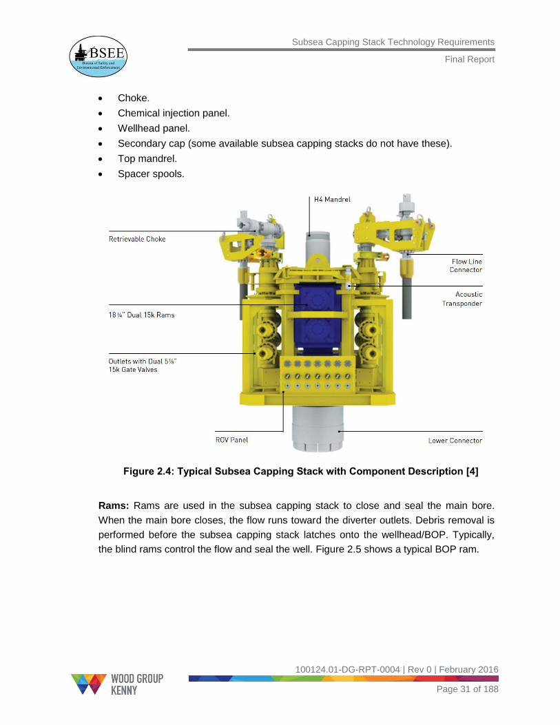
Choke.
Chemical injection panel.
Wellhead panel.
Secondary cap (some available subsea capping stacks do not have these).
Top mandrel.
Spacer spools.
Figure 2.4: Typical Subsea Capping Stack with Component Description [4]
Rams: Rams are used in the subsea capping stack to close and seal the main bore.
When the main bore closes, the flow runs toward the diverter outlets. Debris removal is
performed before the subsea capping stack latches onto the wellhead/BOP. Typically,
the blind rams control the flow and seal the well. Figure 2.5 shows a typical BOP ram.

Subsea Capping Stack Technology Requirements
Final Report
100124.01-DG-RPT-0004 | Rev 0 | February 2016
Page 32 of 188
Figure 2.5: BOP Ram [5]
Gate Valves: In some subsea capping stacks, gate valves act as main bore closure
devices instead of rams. These valves must have ROV override capabilities and conform
to API RP 17H [6]. In addition, the valves used must be qualified for flow with solids and
tested to conform to API Specification 6AV1 Class II for sandy service. Figure 2.6 shows
a typical subsea capping stack with gate valves.
Figure 2.6: Subsea Capping Stack with Gate Valves [4]
Wellhead Connector: The wellhead connector, which is shown in Figure 2.7, provides a
profile to latch the subsea capping stack to the wellhead and access to the wellbore in a
secure, pressure-controlled environment. The connector is hydraulically actuated to
interface with the incident well and is operable by ROV intervention.
Gate Valves

Subsea Capping Stack Technology Requirements
Final Report
100124.01-DG-RPT-0004 | Rev 0 | February 2016
Page 33 of 188
Figure 2.7: Wellhead Connector
Diverter Spool Assembly: The diverter spool assembly is located below the BOP and
above the wellhead connector. It diverts the fluid from the vertical main bore to the side
outlets. Figure 2.8 shows the diverter spool assembly that is placed in a container with
two spools on each side.
Figure 2.8: Diverter Spool Assembly with Four Inner Spools [4]
Diverter Isolation Valves: The diverter isolation valves, which are located on the
diverter spool assembly, control the flow through the diverter valves. Figure 2.9 shows
the dual valves used on the Oil Spill Response Limited (OSRL) subsea capping stacks.

Subsea Capping Stack Technology Requirements
Final Report
100124.01-DG-RPT-0004 | Rev 0 | February 2016
Page 34 of 188
Figure 2.9: Dual Valves [4]
Flowline Connectors: The flowline connectors are required for ‘cap and flow’ type
subsea capping stacks to connect to the flexible riser and for fluid transfer to the MCV.
Typically, the connectors have an API Standard flange interface on the flow spool outlets
and are downstream of any chokes. Figure 2.10 shows the flowline connector on the
OSRL subsea capping stacks, respectively.
Figure 2.10: Flowline Connector [4]

Subsea Capping Stack Technology Requirements
Final Report
100124.01-DG-RPT-0004 | Rev 0 | February 2016
Page 35 of 188
Vector Connector with a Choke Valve: The ROV-operated vector connectors are
affixed to the diverter assembly. In the ‘cap only’ containment scenario, the choke valves
on the side outlets are closed, causing complete shut-off of the incident well. Figure 2.11
shows the vector connector with a choke valve.
Figure 2.11: Vector Connector with a Choke Valve [4]
Secondary Cap: The secondary cap is provided to the top mandrel of the subsea
capping stack as an additional safety barrier. This is done after the main bore and
diverter outlets are successfully sealed. Figure 2.12 shows the secondary
containment cap.

Subsea Capping Stack Technology Requirements
Final Report
100124.01-DG-RPT-0004 | Rev 0 | February 2016
Page 36 of 188
Figure 2.12: Secondary Containment Cap [2]
Wellhead Panel: The wellhead panel provides access to the ROV for operating the
latching, unlatching, locking, and unlocking mechanisms of the wellhead connector. A
schematic of the wellhead panel is shown in Figure 2.13.
Figure 2.13: Wellhead Panel Schematic [4]

Subsea Capping Stack Technology Requirements
Final Report
100124.01-DG-RPT-0004 | Rev 0 | February 2016
Page 37 of 188
Chemical Injection Panel: The chemical injection panel shown in Figure 2.14 provides
access to the ROV for the injection of hydrate inhibitors and dispersants.
Figure 2.14: Chemical Injection Panel [4]
2.4 Well Containment Response Work Flow
2.4.1 General
This section outlines the sequence of actions and a description of the equipment used to
stop or redirect the flow of hydrocarbons from an uncontrolled well. The well containment
process can vary from one well to another, depending on the shut-in pressures and
temperatures and the incident well conditions. The response times4 depend on several
factors such as the:
Method of mobilization
Equipment testing
Availability of vessels
Disassembly and containerizing of equipment (for air transport)
Availability of skilled personnel
Figure 2.15 provides the well containment work flow in response to a subsea blowout.
The first step is to perform a site survey and conduct an initial assessment, followed by
4 Response time is the time needed to mobilize and deploy the system from the notification of the
uncontrolled hydrocarbon release to the moment a cap or full containment system is connected to the well and is functioning.

Subsea Capping Stack Technology Requirements
Final Report
100124.01-DG-RPT-0004 | Rev 0 | February 2016
Page 38 of 188
debris removal and dispersant application operations. After the incident wellsite has
been cleaned, capping equipment is deployed to shut in the flow of the well. If the
wellbore pressure rises above the allowable pressure during the shut-in process, the well
cannot be shut in completely, and the hydrocarbons need to be captured and collected
at the surface.
Figure 2.15: Well Containment Response Work Flow [7]
Simultaneous Operations (SIMOPS) is the management of simultaneous operations to
ensure the safe execution of response activities to avoid potential clashes between
activities that could bring about an undesired event. A proper SIMOPS management
program involves an exchange of information to enable the efficient use of resources to
accomplish multifaceted missions safely. During a response, the comprehensive
SIMOPS plan includes deployment and operation of the well containment equipment.
Site Survey &
Initial Assessment
Debris Removal
Subsea Dispersant
Application
Capping
Capture & Collection
Decontamination
& Demobilization
SIMOPS
Relief Well
Time

Subsea Capping Stack Technology Requirements
Final Report
100124.01-DG-RPT-0004 | Rev 0 | February 2016
Page 39 of 188
2.4.2 Site Survey and Initial Assessment
In a well control scenario, the Operator5 must first assess the health and safety of all
personnel onboard the rig or production platform. After the wellbeing of personnel has
been secured, the Operator (also called the Responsible Party [RP]) begins an in-depth
assessment of the incident site.
A surface (aerial or vessel) and subsea (ROV) site survey is performed to identify
the following:
Existence of debris
Potential discharge source(s)
Status of surface and subsea infrastructure
General magnitude of the release of hydrocarbons
The information obtained by the ROV site assessment is used to determine the suitable
equipment for the conditions of the specific wellsite. After the site assessment is
completed, the RP works with the subsea capping stack company6 and regulators to
determine the containment approach, specific equipment, and configuration needed to
contain the well.
In general, one of the two containment approaches is used: cap only or cap and flow. In
a cap only scenario, a subsea capping stack is attached to the incident well, and flow
from the incident well is shut off through the closure of valves on the subsea capping
stack’s main bore and diverter outlets. In a cap and flow scenario, the subsea capping
stack also redirects the flow of hydrocarbons through flexible pipes and risers to the
capture vessels for processing. The selection of the subsea capping stack and subsea
equipment is based on the containment approach, temperature, and pressure and the
proximity to other wells and risers.
Following equipment selection, mobilization of the containment equipment and the
response vessels begins.
2.4.3 Debris Removal
If debris is detected during the initial site survey, debris removal becomes critical to
ensure a safe working environment and to provide access to the wellsite for intervention.
5 In the oil and gas industry, the Operator is the company responsible for exploration, development, and
production of an oil or gas well. 6 The subsea capping stack company can be a consortium or an independent company that provides
equipment, resources, and expertise for subsea well containment.

Subsea Capping Stack Technology Requirements
Final Report
100124.01-DG-RPT-0004 | Rev 0 | February 2016
Page 40 of 188
The area around the wellhead is cleared to prepare for installation of the subsea capping
stack and equipment.
The debris removal tools include subsea shears, pipe grapplers, rock grapplers, chop
saws, super grinders, diamond wire cutters, ROV knives, and torque tools. Shears are
used for activities such as cutting a bent or broken riser and shearing a pipe. ROV utility
cutting tools (for example, super grinders) are used to remove light debris and prepare
the site.
The most widely used debris clearance tools are:
Remote control unit – for remote control of pressure and flow on two independent
lines that are controlled from the surface
Impact wrench – to produce impact torque
Hydraulic stud removal tool
Flying Lead Orientation Tool (FLOT)
Torque tool Class 4 – to operate rotary valves from Classes 1-4
Dredge pump – for the disposal of sediments and gravel
Manipulator inspection camera – for inspection in confined spaces
2D multibeam imaging sensor – to search and navigate in zero visibility water
3D multibeam imaging sensor – to produce 3D point clouds from a
stationary location
Linear Valve Override Tool (LVOT) – to use ROV hydraulics for moving a piston to
actuate a gate valve stem on subsea manifolds
Multi-purpose cleaning tools
Pipe grappler tool, rock grappler, 22-in. chop saw, 60-in. chop saw, super grinder,
diamond wire cutter, hydraulic cutter, and ROV knife
2.4.4 Subsea Dispersant Application
The ROV and other subsea systems may be used to inject the dispersant7 directly into
the hydrocarbon flow stream. A dispersant is used on the surface and subsea to break
up oil and gas into smaller particles, which makes it easier for microorganisms to
consume the oil and less hazardous for responding personnel on the surface. This
process can minimize the amount of oil that reaches the shore and reduce
environmental impact to marshes, wetlands, and beaches.
Subsea dispersants can:
7 Additional information about dispersants can be found on Environmental Protection Agency (EPA)
website (http://archive.epa.gov/bpspill/web/html/dispersants.html).

Subsea Capping Stack Technology Requirements
Final Report
100124.01-DG-RPT-0004 | Rev 0 | February 2016
Page 41 of 188
Provide safer working conditions by reducing the exposure of surface vessels and
personnel to volatile organic compounds (VOCs).
Reduce the environmental impact of oil exposure and enhance dispersion and bio-
degradation of oil in water.
Reduce the need for surface recovery, in situ burning, and surface dispersant
operations, thereby reducing the exposure of response personnel to accidents
during these operations.
Dispersant is applied through coil tubing or umbilical that is connected to tanks and
pumps on the vessel. Subsea dispersant equipment includes:
Dispersant wands – to direct dispersant in a set direction.
Dispersant wand spears (spear-type wands) – to direct dispersant in a set direction.
A 1-in. chemical jumper – to transfer dispersant from the Coil Tubing Termination
Head (CTTH) to the subsea manifold.
Deployment rack – for transportation and storage of chemical jumpers.
CTTH – for interfacing with two flexible lines through high flow hot stabs.
Manifold.
2.4.5 Capping
Capping operations involve the installation of a subsea capping stack onto the
wellhead/BOP and closure of the ram and choke valves to shut in the well and stop the
discharge of hydrocarbons.
Based on the information gained from ROV site assessment, the subsea capping stack
and the support equipment (such as the subsea hydraulic accumulator and additional
connector interface adapters) are mobilized from the storage base. Pre-deployment
testing is conducted at the quayside to verify the functioning and pressure integrity of the
equipment. The subsea capping stack and the support equipment (such as ROV skids,
accumulator module) are flown to the incident site and are deployed from the vessel to
the wellhead or the BOP, depending on the incident well conditions.
The subsea capping stack vertical bore is closed, followed by the closure of valves on
the diverter outlets. During the valve closure process, the shut-in pressure in the well is
monitored. If the pressures are higher than the maximum allowable pressure, the valve
closure process must be stopped because the well equipment may not be able to
withstand the pressures. This may cause a rupture below the seafloor, which can be
difficult to contain.
Currently available subsea capping stacks can both seal the well and redirect the flow of
fluids through flexible pipes and risers to the capture vessels.

Subsea Capping Stack Technology Requirements
Final Report
100124.01-DG-RPT-0004 | Rev 0 | February 2016
Page 42 of 188
2.4.6 Capture and Collection
If for any reason the capping of an uncontrolled well does not succeed in stopping the
flow of hydrocarbons, a capture and collection system must be used. Capture and
collection systems (also called containment systems) are used to capture, collect, and
transport escaping hydrocarbons from the subsea well to the surface for storage and
disposal. The capture and collection system includes the following equipment:
Surface containment vessels – store and process captured hydrocarbons
Umbilical Termination Assembly – controls the subsea capping stack and provides
real time data about the well
Subsea Umbilicals, Risers, and Flowlines (SURF) equipment – connects the subsea
equipment to the topside equipment
Subsea systems and infrastructures (for example, manifolds, flexible flowlines,
Pipeline End Termination [PLET]) – route hydrocarbons from the subsea capping
stack to the riser
Subsea Dispersant System – injects dispersants to mitigate hydrocarbons in water
Hydrate Inhibition System – prevents hydrate formation within the subsea equipment
Top Hat or Containment Dome – captures leaking fluid that is vented from the
incident well
If a subsea capping stack cannot make a successful connection with the wellhead
(because of damage to the wellhead), a containment dome can be used to capture the
hydrocarbons flowing to the environment. A containment dome is an unpressurized
structure that is placed over damaged or faulty subsea equipment to collect leaking
hydrocarbons. Containment domes are also referred to as ‘cofferdams’ or ‘hats.’
Hydrate inhibition systems are typically used in conjunction with the well containment
systems to prevent subsea oil from freezing up and forming hydrates that can clog tubes
that collect and route oil and gas to the surface. Methanol or glycol solutions are used to
prevent potential hydrate formation and blockage.

Subsea Capping Stack Technology Requirements
Final Report
100124.01-DG-RPT-0004 | Rev 0 | February 2016
Page 43 of 188
2.4.7 Relief Well
As the well containment operations are taking place, SIMOPS are performed to drill a
relief well. A relief well is a secondary well that is drilled with the intent of intersecting the
target well at some pre-determined distance below the seabed. The location of the relief
well must be at a minimum safe distance from the incident wellsite so as to ensure safe
relief drilling operations and avoid interference with the well containment operations. The
purpose of the relief well is to permanently kill the incident well by pumping salt water,
mud, and concrete into the incident well.
Aside from the directional (angled) drilling required to drill a relief well, there is no
difference between drilling a relief well and a regular well. Figure 2.16 provides the
schematic of the two relief wells that were drilled to kill the Macondo well in 2010.
Figure 2.16: Schematic of Relief Well Drilled During the 2010 Macondo Incident [8]
This report focuses on the technical capabilities and availability of subsea capping
stacks and does not provide details of the capture and collection systems or relief well
operations.

Subsea Capping Stack Technology Requirements
Final Report
100124.01-DG-RPT-0004 | Rev 0 | February 2016
Page 44 of 188
3.0 Available Subsea Capping Stacks and their Technical Capabilities
3.1 Introduction
This section provides a brief history of subsea capping stacks and reviews
industry-owned consortiums and their capabilities for responding to well control events.
In addition, the subsea capping stacks that are available globally are enumerated and
their technical capabilities, storage locations, and serving regions are provided.
3.2 Subsea Capping Stacks Consortiums and Organizations
Following the Macondo incident in 2010, the U.S. federal government enacted a drilling
moratorium that halted drilling activity in the Gulf of Mexico (GOM)8. During this time, the
industry recognized the need to improve containment capabilities and emergency
response protocols. As a result, U.S. oil companies formed two cooperative containment
groups—Marine Well Containment Company (MWCC) and HWCG LLC (formerly called
the Helix Well Containment Group)—to develop and maintain the equipment and
procedures needed during uncontrolled well flowing conditions. The drilling moratorium
was lifted in October 2010.
U.S. regulations became more stringent and required oil companies to have access to
capping and containment equipment and relief rigs and the expertise to stop or redirect
the flow of hydrocarbons during a well control incident. U.S. regulators made this
requirement mandatory for issuing permits to drill in the GOM.
MWCC and HWCG LLC maintain the subsea capping stacks and containment
equipment in a response-ready state, and they develop generic installation and
operational procedures. They also support well permitting by providing system
documentation to member companies to develop their permit applications to BSEE. A
detailed description of these companies is provided in Sections 3.2.1 and 3.2.2.
Regulators and oil companies around the world have also started evaluating their drilling
and incident response procedures. Oil & Gas UK9 established the Oil Spill Prevention
and Response Advisory Group (OSPRAG) to review industry practices for the United
Kingdom Continental Shelf (UKCS).
8 GOM in this report refers to U.S. Gulf of Mexico Outer Continental Shelf
9 Oil & Gas UK is the leading trade association for the United Kingdom offshore oil and gas industry. It
has been established on the foundation of the UK Offshore Operators Association. The association is the leading representative body for the U.K. offshore oil and gas industry.

Subsea Capping Stack Technology Requirements
Final Report
100124.01-DG-RPT-0004 | Rev 0 | February 2016
Page 45 of 188
In November 2010, Oil & Gas UK procured a subsea capping stack for the UKCS,
including the west of Shetland. The OSPRAG Technical Review Group, working with BP,
oversaw the design and development of this subsea capping stack.
In response to the April 2010 Macondo incident in the GOM and other similar incidents
that preceded it, the International Association of Oil & Gas Producers (IOGP)10 formed
the Global Industry Response Group (GIRG). GIRG was tasked with examining the
industry’s capability to respond to a major well control incident and identifying areas for
improvement. GIRG did this by identifying and gathering work performed by IOGP’s
member companies and national regulators in response to the Macondo and Montara11
oil spills and other well control incidents.
The three groups that IOGP formed to respond to GIRG’s recommendations were:
The Wells Expert Committee – with a focus on incident prevention
The Oil Spill Response Joint Industry Project – to work with the API to evaluate
recommendations and enhance coordination on oil spill response
The Subsea Well Response Project (SWRP) – consortium to deliver improved
capping response in support of containment solutions [9]
SWRP was launched in May 2011 and is a joint non-profit initiative of eight major oil and
gas companies (BG Group, BP, Chevron, ConocoPhillips, ExxonMobil, Shell, Statoil,
Total) that are working together to enhance the industry’s capacity to respond to subsea
well control incidents. SWRP collaborates with Oil Spill Response Limited (OSRL) to
maintain and store well containment equipment at multiple global locations. Members
can mobilize and deploy this equipment in the event of an incident. OSRL is owned by
45 member companies and supports 100 associate members.
Wild Well Control (WWC), an independent firefighting and well control services
company, formed the WellCONTAINED consortium with 41 member companies and
owns two subsea capping stacks that can be deployed internationally.
Some of the major oil companies, such as Shell and BP, also own subsea capping
stacks in various regions around the world. These subsea capping stacks are built for
their specific needs and may not be available for use by other Operators.
10
IOGP is a global forum in which members identify and share best practices to achieve improvements in health, safety, environment, security, social responsibility, engineering, and operations. 11
The Montara oil spill was an oil and gas leak that took place in the Montara oil field in the Timor Sea, off the northern coast of Western Australia. The well continued leaking for 74 days before it was stopped by pumping mud into the well and the wellbore cemented.

Subsea Capping Stack Technology Requirements
Final Report
100124.01-DG-RPT-0004 | Rev 0 | February 2016
Page 46 of 188
3.2.1 Marine Well Containment Company
In July 2010, four major oil and gas Operators (Shell, Chevron, ConocoPhillips, and
ExxonMobil) formed the MWCC to provide containment response capability for
the GOM.
Other major oil companies (Anadarko, Apache, BHP Billiton, BP, Hess, and Statoil) have
also joined MWCC, and it currently has ten member companies.
MWCC also provides coverage for non-member Operators on a per-well basis [2].
MWCC is responsible for the following functions:
Support well permitting by providing system documentation. Member companies use
the documentation to develop their permit submissions, including generic
procedures for containment preparation, to BSEE.
Maintain equipment in a response-ready state
Provide regular training and drills to member companies to ensure that they are
ready to respond
Develop and maintain generic installation and operational procedures
Maintain dispersant stock piles and contracts to be ready to respond
Capture lessons learned and oversee the refurbishment and return of MWCC
equipment to storage locations as a follow-up to any incident
MWCC has a full-time staff of about 70 people who have Operator and service company
experience, many of whom worked on the containment of the Macondo well. MWCC also
has 100 reservists (Reservist Response Team) who are employed by Wood Group PSN,
a division of Wood Group. These personnel, who operate platforms throughout the
GOM, are fully trained in containment equipment operations. In the event of an incident,
they will be mobilized to respond. MWCC works with regulators from BSEE and the U.S.
Coast Guard to ensure that all expectations are met.
3.2.1.1 MWCC Equipment and Capabilities
MWCC equipment is available for use in the deep water12 GOM in depths from 500 ft. to
10,000 ft., temperatures up to 350°F, and pressures up to 15,000 pounds per square
inch (psi). The system can cap only or cap and flow an incident well, and it has the
capability to process up to 100,000 barrels of liquid per day and up to 200 million cubic
feet of gas per day. Additionally, MWCC can store up to 700,000 barrels of liquid in each
of its two modular capture vessels (MCVs). The liquid is then brought onshore by shuttle
12
Water depth greater than 500 ft. is considered ‘deep water.’
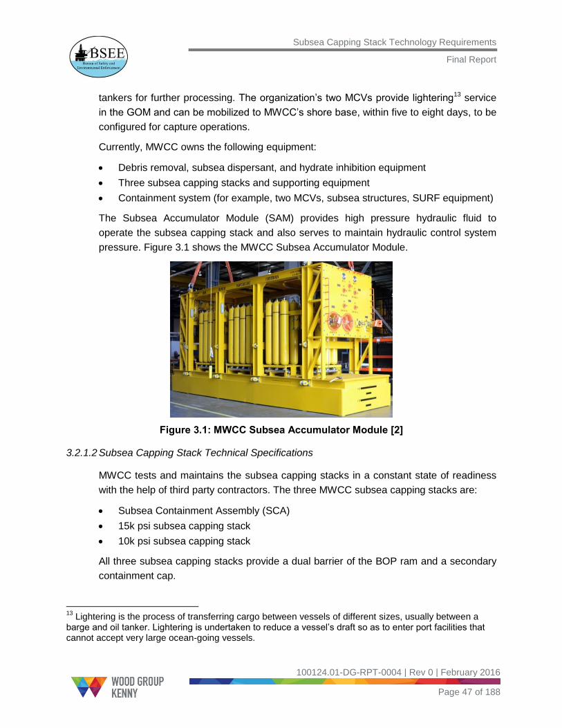
Subsea Capping Stack Technology Requirements
Final Report
100124.01-DG-RPT-0004 | Rev 0 | February 2016
Page 47 of 188
tankers for further processing. The organization’s two MCVs provide lightering13 service
in the GOM and can be mobilized to MWCC’s shore base, within five to eight days, to be
configured for capture operations.
Currently, MWCC owns the following equipment:
Debris removal, subsea dispersant, and hydrate inhibition equipment
Three subsea capping stacks and supporting equipment
Containment system (for example, two MCVs, subsea structures, SURF equipment)
The Subsea Accumulator Module (SAM) provides high pressure hydraulic fluid to
operate the subsea capping stack and also serves to maintain hydraulic control system
pressure. Figure 3.1 shows the MWCC Subsea Accumulator Module.
Figure 3.1: MWCC Subsea Accumulator Module [2]
3.2.1.2 Subsea Capping Stack Technical Specifications
MWCC tests and maintains the subsea capping stacks in a constant state of readiness
with the help of third party contractors. The three MWCC subsea capping stacks are:
Subsea Containment Assembly (SCA)
15k psi subsea capping stack
10k psi subsea capping stack
All three subsea capping stacks provide a dual barrier of the BOP ram and a secondary
containment cap.
13
Lightering is the process of transferring cargo between vessels of different sizes, usually between a barge and oil tanker. Lightering is undertaken to reduce a vessel’s draft so as to enter port facilities that cannot accept very large ocean-going vessels.

Subsea Capping Stack Technology Requirements
Final Report
100124.01-DG-RPT-0004 | Rev 0 | February 2016
Page 48 of 188
The SCA is primarily used in cap and flow scenarios. The SCA’s design allows the
subsea capping stack to be disassembled into two sub-assemblies, which facilitates
handling and transportation. It has full electro-hydraulic (EH) control capability, which
allows operation from the top sides. Table 3.1 provides the technical specifications of
the SCA.
Table 3.1: MWCC SCA Technical Specifications [10]
MWCC Subsea Containment Assembly (SCA)
Parameter Value
Manufacturer Aker Solutions
Primary Bore 18-3/4 in. with dual rams
Diverter Outlets (4) 5-1/8 in. with dual
gate valves
Pressure Rating 15,000 psi
Temp. Rating 250F
Water Depth 10,000 ft.
Soft Shut-in Capability Yes – with 4 chokes
Flow Back Capability Yes – 100,000 bpd
Chemical Injection Yes – Hydrate
remediation/dispersant
Controls EH-MUX and ROV
Installation Method Drill Pipe or Wire
Weight/Air Freight 170 tons/No
Dimensions (LxWxH) —
Storage Location Ingleside, Texas
Serving Region GOM
The 15k psi subsea capping stack is the only capping stack that is capable of handling
temperatures up to 350°F, and it can be used to cap only or cap and flow wells. This
subsea capping stack was used in the deployment demonstration to BSEE in 2012.
Table 3.2 provides the technical specifications of the 15k psi subsea capping stack.

Subsea Capping Stack Technology Requirements
Final Report
100124.01-DG-RPT-0004 | Rev 0 | February 2016
Page 49 of 188
Table 3.2: MWCC 15k psi Subsea Capping Stack Technical Specifications [10]
MWCC 15k psi Subsea Capping Stack
Parameter Value
Manufacturer Trendsetter Engineering
Primary Bore 18-3/4 in. with single ram
Diverter Outlets (4) 5-1/8 in. with dual
gate valves
Pressure Rating 15,000 psi
Temp. Rating 350F
Water Depth 10,000 ft.
Soft Shut-in Capability Yes – with 2 chokes
Flow Back Capability Yes – 100,000 bpd
Chemical Injection Yes – Hydrate
remediation/dispersant
Controls ROV with Subsea
Accumulator Module
Installation Method Drill Pipe or Wire
Weight/Air Freight 93 tons/No
Dimensions (LxWxH) 11.5 x 11.5 x 18.5 ft.
Storage Location Ingleside, Texas
Serving Region GOM
The 10k psi subsea capping stack will be used mainly in cap only scenarios in which well
casings and riser systems are closely spaced, such as Tension-Leg Platform (TLP) and
spar applications where wells are located beneath a floating production facility. Table 3.3
provides the technical specifications of the 10k psi subsea capping stack.

Subsea Capping Stack Technology Requirements
Final Report
100124.01-DG-RPT-0004 | Rev 0 | February 2016
Page 50 of 188
Table 3.3: MWCC 10k psi Subsea Capping Stack Technical Specifications [10]
MWCC 10k psi Subsea Capping Stack
Parameter Value
Manufacturer Trendsetter Engineering
Primary Bore 7-1/16 in. with dual rams
Diverter Outlets (2) 4-in. with single gate
valves
Pressure Rating 10,000 psi
Temp. Rating 300F
Water Depth 10,000 ft.
Soft Shut-in Capability Yes – with 2 chokes
Flow Back Capability Yes
Chemical Injection Yes – Hydrate
remediation/dispersant
Controls ROV with Subsea
Accumulator Module
Installation Method Wire
Weight/Air Freight 50 tons/No
Dimensions (LxWxH) 9 x 9 x 18.25 ft.
Storage Location Ingleside, Texas
Serving Region GOM
3.2.1.3 Storage Locations
The three MWCC subsea capping stacks are stored at a shore base in Ingleside, Texas.
Figure 3.2 shows the location of the capping stacks on a world map.
Throughout this report, the subsea capping stacks that serve the region around its
storage area only are called ‘local’ subsea capping stacks. The local subsea capping
stacks are transported by sea and typically reach the incident site in 24–48 hours. The
subsea capping stacks that serve globally and can be transported by air called the
‘global’ subsea capping stacks. Transport of the global subsea capping stacks may
require up to 14 days, depending on the location of the incident site.

Subsea Capping Stack Technology Requirements
Final Report
100124.01-DG-RPT-0004 | Rev 0 | February 2016
Page 51 of 188
Figure 3.2: MWCC Subsea Capping Stack Storage Location
3.2.2 HWCG LLC
HWCG LLC is the second consortium that has been formed to support operations in the
GOM. The member companies of the consortium are shown in Table 3.4.
Table 3.4: Member Companies of HWCG LLC
Bennu Oil & Gas, LLC
Cobalt International Energy, Inc.
Deep Gulf Energy LP
ENI U.S. Operating Company Inc.
EnVen Energy Ventures, LLC
Energy Resource Technology GOM, Inc.
Freeport-McMoRan Oil & Gas LLC
LLOG Exploration Company, LLC
Marathon Oil Company
Marubeni Oil & Gas (USA) Inc.
Murphy Exploration & Production
Company (USA)
Noble Energy Services, Inc.
Repsol Services Company
Stone Energy Corporation
Walter Oil & Gas Corporation
W&T Offshore, Inc.

Subsea Capping Stack Technology Requirements
Final Report
100124.01-DG-RPT-0004 | Rev 0 | February 2016
Page 52 of 188
HWCG LLC is responsible for the following functions:
Supports well permitting by providing documentation for the member companies to
develop their APDs that are submitted to BSEE
Works with subcontractors to maintain equipment in a response-ready state
Conducts periodic subsea incident response drills with member companies
Captures lessons learned as a follow-up to any incident
As part of the Mutual Aid program, HWCG LLC is provided with 12 personnel from each
member company to respond to a well control incident. The periodic response drills
include coordinating detailed plans for well containment operations to train personnel to
be ready to respond. HWCG LLC works with regulators from BSEE and the U.S. Coast
Guard to ensure that all expectations are met.
3.2.2.1 HWCG LLC Equipment and Capabilities
Along with owned assets, HWCG LLC maintains agreements with eleven service
companies. HWCG LLC also maintains 30 other service providers to provide equipment
and personnel that would be useful during a subsea blowout response. HWCG LLC
manages the logistics, planning, and facilitation of deep water incident response.
The HWCG LLC response system builds on the equipment used in the containment of
the Macondo well, including the Helix Fast Response System (HFRS) with the Q4000
intervention vessel and the Helix Producer 1 from Helix Energy Solutions Group (HESG).
Current HWCG LLC well containment systems include [11]:
The ability to fully operate in water depths of up to 10,000 ft.
Two dual ram subsea capping stacks: 15,000 psi and 10,000 psi
The ability to capture and process 130,000 barrels of oil per day and 220 million
cubic feet of gas per day
3.2.2.2 Subsea capping stack Technical Specifications
HWCG LLC has access to two subsea capping stacks:
1. A 13-5/8-in. 10,000 psi subsea capping stack, which is owned and maintained
by HESG
2. An 18-3/4-in. 15,000 psi subsea capping stack, which is owned and maintained by
Trendsetter Engineering
Table 3.5 provides the technical specifications and a picture of the 10k psi subsea
capping stack. Table 3.6 provides the technical specifications and a picture of the
15k psi subsea capping stack.

Subsea Capping Stack Technology Requirements
Final Report
100124.01-DG-RPT-0004 | Rev 0 | February 2016
Page 53 of 188
Table 3.5: HWCG LLC 10k psi Subsea Capping Stack Technical Specifications
HWCG LLC 10k psi Subsea Capping Stack
Parameter Value
Manufacturer Worldwide Oilfield
Machine (WOM)
Primary Bore 13-5/8 in. with dual rams
Diverter Outlets (2) 5-1/8 in. with dual
gate valves
Pressure Rating 10,000 psi
Temp. Rating 250F
Water Depth 10,000 ft.
Soft Shut-in Capability Yes
Flow Back Capability Yes
Chemical Injection Yes – Hydrate
remediation/dispersant
Controls ROV with Subsea
Accumulator Module
Installation Method Drill pipe or Wire
Weight/Air Freight 72 tons/No
Dimensions (LxWxH) —
Storage Location Ingleside, Texas
Serving Region GOM

Subsea Capping Stack Technology Requirements
Final Report
100124.01-DG-RPT-0004 | Rev 0 | February 2016
Page 54 of 188
Table 3.6: HWCG LLC 15k psi Subsea Capping Stack Technical Specifications
HWCG LLC 15k psi Subsea Capping Stack
Parameter Value
Manufacturer Trendsetter Engineering
Primary Bore 18-3/4 in. with dual rams
Diverter Outlets (2) 5-1/8 in. with single
gate valves
Pressure Rating 10,000 psi
Temp. Rating 350F
Water Depth 15,000 ft.
Soft Shut-in Capability Yes – with 2 chokes
Flow Back Capability Yes
Chemical Injection Yes – Hydrate
remediation/dispersant
Controls ROV with Subsea
Accumulator Module
Installation Method Drill Pipe or Wire
Weight/Air Freight 76 tons/No
Dimensions (LxWxH) 11.5 x 11.5 x 19 ft.
Storage Location Houston, Texas
Serving Region GOM

Subsea Capping Stack Technology Requirements
Final Report
100124.01-DG-RPT-0004 | Rev 0 | February 2016
Page 55 of 188
3.2.2.3 Storage Location
The HWCG LLC 10k psi subsea capping stack is stored in Ingleside, Texas. The 15k psi
subsea capping stack is stored in Houston, Texas. Figure 3.3 shows the HWCG LLC
subsea capping stack storage locations on the world map.
Figure 3.3: HWCG LLC Subsea Capping Stack Storage Location
3.2.3 Oil Spill Prevention and Response Advisory Group
After the 2010 Macondo oil spill, the U.K. oil and gas industry and its regulators and
trade unions collaborated to establish the Oil Spill Prevention and Response Advisory
Group (OSPRAG). OSPRAG includes senior representatives from the U.K.’s regulators,
trade unions, the Maritime & Coastguard Agency (MCA), and the Secretary of State’s
Representative for Maritime Salvage and Intervention (SOSREP).
OSPRAG performed a thorough review of drilling practices in the UKCS to ensure safety
during drilling operations and to enhance existing spill prevention and response
mechanisms. OSPRAG identified and recommended improvements to further strengthen
the U.K.’s ability to respond to a well control incident. As a result, the OSPRAG subsea
capping stack is designed to seal off an uncontrolled well.
OSRL owns and maintains the OSPRAG subsea capping stack and provides access to
the member companies who operate within the UKCS through a supplemental
agreement [12].
3.2.3.1 OSPRAG Subsea Capping Stack Technical Capabilities
The OSPRAG subsea capping stack can be quickly deployed [13]:
At the widest possible range of wells and oil spill scenarios that could occur in the
UKCS, including West of Shetland.

Subsea Capping Stack Technology Requirements
Final Report
100124.01-DG-RPT-0004 | Rev 0 | February 2016
Page 56 of 188
At water depths of between 328 ft. and 10,000 ft.
In wave heights of up to 16 ft.
From a wide variety of multi-service vessels or drilling rigs.
To wells up to 15,000 psi and 250°F.
Onto a flowing well up to 75,000 barrels a day.
Table 3.7 provides the technical specifications of the OSPRAG subsea capping stack.
Table 3.7: OSPRAG Subsea Capping Stack Technical Specifications [13]
OSPRAG Subsea Capping Stack
Parameter Value
Manufacturer Cameron Ltd.
Primary Bore 5-1/8 in. with gate valves
Diverter Outlets 5-1/8 in. with dual gate
valves
Pressure Rating 15,000 psi
Temp. Rating 250F
Water Depth 10,000 ft.
Soft Shut-in Capability Yes
Flow Back Capability Yes – 75,000 bpd
Chemical Injection Yes – Hydrate
remediation/dispersant
Controls ROV
Installation Method Wire
Weight/Air Freight 43.8 tons/No
Dimensions (LxWxH) 13 x 15 x 15 ft.
Storage Location Aberdeen, Scotland
Serving Region UKCS, including West of
Shetland

Subsea Capping Stack Technology Requirements
Final Report
100124.01-DG-RPT-0004 | Rev 0 | February 2016
Page 57 of 188
3.2.3.2 Storage Locations
The OSPRAG subsea capping stack is stored in Aberdeen, Scotland. Figure 3.4 shows
the location of this subsea capping stack on a world map.
Figure 3.4: OSPRAG Subsea Capping Stack Storage Location
3.2.4 Subsea Well Response Project/Oil Spill Response Limited
SWRP collaborates with OSRL to develop capping and containment systems. OSRL has
developed international base locations and has made containment equipment available
for the international industry [4].
Subsea Well Intervention Services (SWIS) is OSRL’s dedicated subsea division, and it
provides OSRL members with the opportunity to access a full subsea intervention
capability (dispersant, capping, and containment). OSRL SWIS owns, maintains, and
stores the equipment in a response-ready state at different strategic locations around
the world [4].
3.2.4.1 OSRL Capabilities
The OSRL SWIS equipment includes:
Two Subsea Incident Response Toolkits (SIRTs).
Four subsea capping stacks.
A Containment Toolkit [14].
The equipment is transportable by land, air, and sea and can be used by OSRL
members through supplementary agreements. The equipment is strategically stored
around the globe for efficient deployment.

Subsea Capping Stack Technology Requirements
Final Report
100124.01-DG-RPT-0004 | Rev 0 | February 2016
Page 58 of 188
The SIRTs are stored at the Oceaneering facilities in Stavanger, Norway, and Macae,
Brazil. The SIRTs are split into three main systems:
1. Debris Clearance System: This system consists of various tools to allow access for
dispersant applications and work on BOPs. The system also includes tools for site
surveys before the work begins, including torque tools, cutting tools, and grappling
tools. Figure 3.5 provides a schematic of the OSRL debris clearance system.
Figure 3.5: Schematic of OSRL Debris Clearance System [15]
2. Subsea Dispersant System: This system allows for the subsea application of oil
dispersant14 at the wellhead. This will create safer surface working conditions for
response personnel and will enhance oil degradation. This system includes
dispersant wands, a CTTH, jumpers to transfer dispersant from the CTTH to the
subsea manifold, deployment racks for flying leads, and a manifold. Figure 3.6
provides the schematic of the OSRL subsea dispersant system.
14
OSRL is implementing a global stockpile of 5000 m3 of dispersant on behalf of the members. The
dispersant stockpile is stored at various locations to enable quick access and ensure availability of sufficient stock. If necessary, 100% of the stockpile can be mobilized to an individual incident.

Subsea Capping Stack Technology Requirements
Final Report
100124.01-DG-RPT-0004 | Rev 0 | February 2016
Page 59 of 188
Figure 3.6: Schematic of OSRL Subsea Dispersant System [15]
3. BOP Intervention Equipment: In the unlikely event that the rig fails to close the BOP,
emergency BOP intervention is required. The components of the intervention
equipment include ROV-mounted intervention charging skids, high pressure
accumulators, and a BOP intervention manifold. Figure 3.7 provides a schematic of
the OSRL BOP intervention system.
Figure 3.7: Schematic of OSRL BOP Intervention System [15]
These three systems are packed separately and can be used independently of each
other. During a subsea well incident, Oceaneering will work with OSRL to mobilize the
SIRT and will act as a point of contact for technical inquiries.

Subsea Capping Stack Technology Requirements
Final Report
100124.01-DG-RPT-0004 | Rev 0 | February 2016
Page 60 of 188
During a subsea well response incident, Trendsetter Engineering prepares the subsea
capping stack system for deployment by performing the following tasks:
Mobilize engineers to the location of the chosen subsea capping stack system.
For sea mobilization – run pre-deployment tests
For air mobilization – dismantle and pack the subsea capping stack into containers
Send engineers to the in-country port to reassemble and run pre-deployment tests,
subject to a separate contract with the Incident Owner
Act as an in-country point of contact for technical enquiries
The Containment Toolkit [14] is stored in containers at warehouses and is ready to be
transported to the nominated delivery point. Parts of the Containment Toolkit are
strategically stored in Brazil, Norway, the U.K., and the U.S. All equipment is
transportable by sea and air except for the flexible flowlines and jumpers, which are
stored on reels and are transportable only by sea. Figure 3.8 shows the storage
locations of various items of equipment that are part of the Containment Toolkit.
Because the flexible flowlines and jumpers are not air transportable, they are stored at
various locations around the world to enable faster response during a flowing well
scenario.
Figure 3.8: OSRL Global Containment Equipment Locations [16]

Subsea Capping Stack Technology Requirements
Final Report
100124.01-DG-RPT-0004 | Rev 0 | February 2016
Page 61 of 188
3.2.4.2 Subsea Capping Stack Technical Specifications
The subsea capping stacks are designed and optimized to operate in a variety of
conditions around the world. As a result of the different scenarios, OSRL’s equipment is
designed to be adaptable and easily reconfigurable to address the majority of scenarios
in which incidents might arise.
The equipment includes four subsea capping stacks:
Two 18-3/4 in. bore subsea capping stacks, which were developed to handle
pressures up to 15,000 psi
Two 7-1/16 in. bore subsea capping stacks, which were designed for pressures up
to 10,000 psi.
All four subsea capping stacks are designed from one common structure, which provides
greater component compatibility and flexibility to handle a variety of scenarios. They
have common pipe work, valves, chokes, and spools, all of which are rated to
15,000 psi. The key difference is the use of 7-1/16 in. 10,000 psi gate valves for the
10,000 psi stacks and 18-3/4 in. 15,000 psi rams for the 15,000 psi stacks. Table 3.8 and
Table 3.9 provide the technical specifications of the 15k psi and 10k psi subsea capping
stacks, respectively.

Subsea Capping Stack Technology Requirements
Final Report
100124.01-DG-RPT-0004 | Rev 0 | February 2016
Page 62 of 188
Table 3.8: OSRL 15k psi Subsea Capping Stack Technical Specifications [17]
Two OSRL 15k psi Subsea Capping Stacks
Parameter Value
Manufacturer Trendsetter Engineering
Primary Bore 18-3/4 in. with dual rams
Diverter Outlets (4) 5-1/8 in. with dual
gate valves
Pressure Rating 15,000 psi
Temp. Rating 302F
Water Depth 10,000 ft.
Soft Shut-in Capability Yes – with 4 chokes
Flow Back Capability Yes – 100,000 bpd
Chemical Injection Yes – Hydrate
remediation/dispersant
Controls ROV with Subsea
Accumulator Module
Installation Method Drill Pipe or Wire
Weight/Air Freight 120 metric tons/Yes
Dimensions (LxWxH) 15.4 x 13.6 x 19 ft.
Storage Location Norway, Brazil
Serving Region Worldwide
(except GOM)

Subsea Capping Stack Technology Requirements
Final Report
100124.01-DG-RPT-0004 | Rev 0 | February 2016
Page 63 of 188
Table 3.9: SWRP 10k psi Subsea Capping Stack Technical Specifications [17]
Two OSRL 10k psi Subsea Capping Stacks
Parameter Value
Manufacturer Trendsetter Engineering
Primary Bore 7-1/16 in. with dual gate
valves
Diverter Outlets (4) 5-1/8 in. with dual
gate valves
Pressure Rating 10,000 psi
Temp. Rating 302F
Water Depth 10,000 ft.
Soft Shut-in Capability Yes – with 4 chokes
Flow Back Capability Yes – 100,000 bpd
Chemical Injection Yes – Hydrate
remediation/dispersant
Controls ROV
Installation Method Drill Pipe or Wire
Weight/Air Freight 90 metric tons/Yes
Dimensions (LxWxH) 15.4 x 13.6 x 17.3 ft.
Storage Location Singapore, South Africa
Serving Region Worldwide
(except GOM)
3.2.4.3 Storage Locations
The four SWRP subsea capping stacks are stored at different OSRL locations around
the world:
1. Norway – 15k psi subsea capping stack
2. Brazil – 15k psi subsea capping stack
3. South Africa – 10k psi subsea capping stack
4. Singapore – 10k psi subsea capping stack
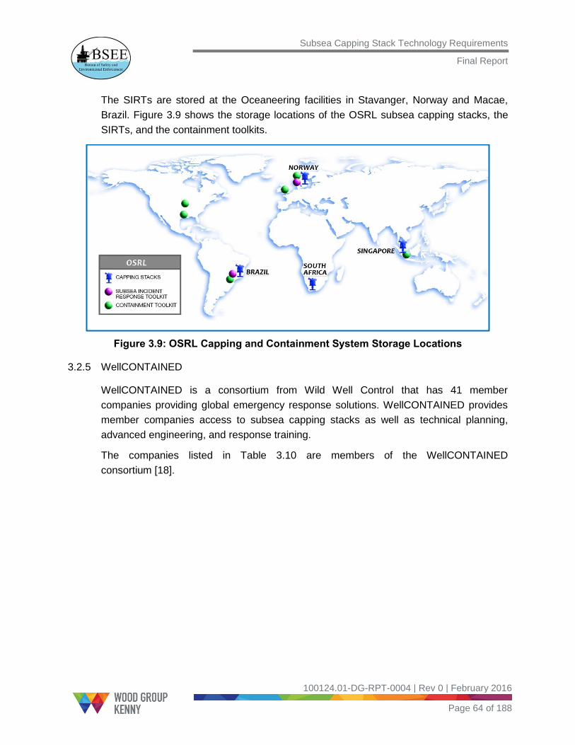
Subsea Capping Stack Technology Requirements
Final Report
100124.01-DG-RPT-0004 | Rev 0 | February 2016
Page 64 of 188
The SIRTs are stored at the Oceaneering facilities in Stavanger, Norway and Macae,
Brazil. Figure 3.9 shows the storage locations of the OSRL subsea capping stacks, the
SIRTs, and the containment toolkits.
Figure 3.9: OSRL Capping and Containment System Storage Locations
3.2.5 WellCONTAINED
WellCONTAINED is a consortium from Wild Well Control that has 41 member
companies providing global emergency response solutions. WellCONTAINED provides
member companies access to subsea capping stacks as well as technical planning,
advanced engineering, and response training.
The companies listed in Table 3.10 are members of the WellCONTAINED
consortium [18].

Subsea Capping Stack Technology Requirements
Final Report
100124.01-DG-RPT-0004 | Rev 0 | February 2016
Page 65 of 188
Table 3.10: Companies in the WellCONTAINED Consortium
AWE Limited
Apache Corporation
Anadarko Petroleum
Corporation
BG Group
BR Petrobras
China National Offshore
Oil Corporation
Cobalt International
Energy
ConocoPhillips
Detnorske
ENI S.p.A.
E.ON UK plc
Exxon Mobil
Corporation
Faroe Petroleum
Freeport-McMoran, Inc.
GDF Suez (now ENGIE
Group)
Hess Corporation
Inpex Corporation
JSC Zarubezhneft
JX Nippon Oil & Energy
Karoon Gas Peru
Kosmos Energy
LUKOIL Oil Company
Lundin Petroleum
Maersk Oil
Niko Resources Ltd
Murphy Exploration &
Production Co.
Norwegian Energy
Company ASA
(NORECO)
OMV Aktiengesellschaft
PDVSA
Pemex
PETRONAS
Premier Oil plc
Queiroz Galvão Group
Repsol
Statoil ASA
Talisman Energy
Total
Tullow Oil plc
VNG Norge AS
Wintershall Holding
GmbH
Woodside
3.2.5.1 WellCONTAINED Capabilities
The response equipment comprises four basic modules [19]:
Debris removal
Subsea dispersant application
Subsea Hydraulic Power Unit (HPU)
Subsea capping stack

Subsea Capping Stack Technology Requirements
Final Report
100124.01-DG-RPT-0004 | Rev 0 | February 2016
Page 66 of 188
The debris removal package contains two sizes of subsea shears that provide cutting
capability of tubular and structural members up to 46 in. The shears can be used to cut
bent or broken risers or shear pipe and can clear areas in preparation for subsea
capping stack installation. In addition to the shears, ROV utility cutting tools, such as the
Super Grinder, are part of the kit and can be used for light debris removal and site
preparation for the subsea capping stack installation. Figure 3.10 shows the shears
positioned to cut a pipe.
Figure 3.10: Shears Positioned to Cut the Riser [18]
The subsea dispersant application package includes all required hardware to facilitate
the application of dispersants subsea from the RP-provided coiled tubing unit through
application wands or ROV hot stabs. Key components include a coiled tubing routing
manifold, a subsea distribution manifold, and a subsea hose deployment reel with more
than 3,000 ft. of hose. The system is rated to 4,500 psi and may also be used to convey
hydrate inhibition and remediation chemicals as well as to control line fluids.
The subsea HPU provides localized hydraulic power to equipment that may be used
during the response operation. The different subsea HPU options include having a
dedicated subsea hydraulic power unit system as well as ROV-deployable hydraulic
skids. The HPU can also be used to perform secondary operation of the BOP.
3.2.5.2 Subsea Capping Stack Technical Specifications
The two subsea capping stacks facilitate the installation chokes for soft shut‐in
operations or gooseneck assemblies for extended flowback/well kill operations. The
subsea capping stack also features chemical injection (dispersant or hydrate
mitigation/remediation) as well as internal pressure and temperature monitoring
capabilities with acoustic transmission of readings to the surface. The stack can be
connected to a BOP or a flex joint, or it can be on top of a wellhead. The subsea capping

Subsea Capping Stack Technology Requirements
Final Report
100124.01-DG-RPT-0004 | Rev 0 | February 2016
Page 67 of 188
stack is deployable on either drill pipe or wire, and deployment is aided by a rig or
crane/winch wire with quick changeout of the running tool interface.
The technical specifications of the two subsea capping stacks are provided in Table 3.11
and Table 3.12.
Table 3.11: WellCONTAINED Aberdeen Subsea Capping Stack Technical Specifications
WellCONTAINED Aberdeen Subsea Capping Stack
Parameter Value
Manufacturer Wild Well Control
Primary Bore 18-3/4 in. with 3 rams
Diverter Outlets (4) 3-1/16 in. with dual
gate valves
Pressure Rating 15,000 psi
Temp. Rating 250F
Water Depth 10,000 ft.
Soft Shut-in Capability Yes – with 2 chokes
Flow Back Capability Yes – 100,000 bpd
Chemical Injection Yes – Hydrate
remediation/dispersant
Controls ROV with subsea HPU
Installation Method Drill pipe or Wire
Weight/Air Freight 96 tons/Yes
Dimensions (LxWxH) 18.4 x 12.9 x 24 ft.
Storage Location Aberdeen, Scotland
Serving Region Worldwide

Subsea Capping Stack Technology Requirements
Final Report
100124.01-DG-RPT-0004 | Rev 0 | February 2016
Page 68 of 188
Table 3.12: WellCONTAINED Singapore Subsea Capping Stack Technical Specifications
WellCONTAINED Singapore Subsea Capping Stack
Parameter Value
Manufacturer Trendsetter Engineering
Primary Bore 18-3/4 in. with dual rams
Diverter Outlets (4) 5-1/8 in. with dual
gate valves
Pressure Rating 15,000 psi
Temp. Rating 250F
Water Depth 10,000 ft.
Soft Shut-in Capability Yes – with 4 chokes
Flow Back Capability Yes – 200,000 bpd
Chemical Injection Yes – Hydrate
remediation/dispersant
Controls ROV with subsea
accumulator module
Installation Method Drill pipe or Wire
Weight/Air Freight 96 tons/Yes
Dimensions (LxWxH) 16 x 14 x 20.5 ft.
Storage Location Singapore
Serving Region Worldwide
3.2.5.3 Storage Locations
The subsea capping stacks and other ancillary equipment are located in Aberdeen and
Singapore. Figure 3.11 shows the WellCONTAINED subsea capping stack global
storage locations.

Subsea Capping Stack Technology Requirements
Final Report
100124.01-DG-RPT-0004 | Rev 0 | February 2016
Page 69 of 188
Figure 3.11: WellCONTAINED Subsea Capping Stack Storage Locations
3.2.6 Shell
Royal Dutch Shell plc, commonly known as Shell, is an Anglo-Dutch multinational oil and
gas company headquartered in the Netherlands and incorporated in the United Kingdom.
Shell owns subsea capping stack systems to cover their global portfolio of subsea wells.
They are used primarily to back up Shell operations in addition to the consortium
systems [20].
Shell owns three subsea capping stacks. One is stored and maintained in Aberdeen,
Scotland, and it is readily available for emergency deployment via air freight to Shell
operations worldwide. After it is on location, it can be deployed via wire or drill pipe from
a rig or a service vessel. The capping system is designed with a 10,000 psi working
pressure for use in water depths up to 10,000 ft.
A second Shell-owned capping system, which is stored and maintained in Singapore,
has a similar design and a 15,000 psi working pressure for use on wells that require this
higher pressure rating. It also provides flexibility for global deployment.
Shell has a well capping system in Alaska that is stored for deployment in the Arctic and
is ready to respond to potential subsea well control events. This system is designed to
deal with Arctic conditions15, including the logistics of a remote location.
15
The Arctic subsea capping stacks are designed such that they can be placed in mudline cellars or glory holes. A mudline cellar allows for the subsea equipment to be installed below the seafloor at depths greater than the anticipated ice gouge depth. The Arctic subsea capping stacks are designed to withstand the low temperatures experienced in the Arctic environment, and materials are selected accordingly.

Subsea Capping Stack Technology Requirements
Final Report
100124.01-DG-RPT-0004 | Rev 0 | February 2016
Page 70 of 188
These Shell-owned capping systems complement the MWCC and OSRL systems that
are available to Shell, and they add to global capability in the event that primary and
secondary well control measures fail to control a well.
Currently, Shell is developing a 20,000 psi-rated cap and a 400F-rated cap to meet
future well needs.
Table 3.13, Table 3.14, and Table 3.15 provide the technical specifications of the
Aberdeen, Singapore, and Arctic subsea capping stacks, respectively.
Table 3.13: Shell Aberdeen Subsea Capping Stack Technical Specifications
Shell Aberdeen Subsea Capping Stack
Parameter Value
Manufacturer Cameron Ltd.
Primary Bore 13-5/8 in. with dual rams
Diverter Outlets —
Pressure Rating 10,000 psi
Temp. Rating —
Water Depth 10,000 ft.
Soft Shut-in Capability —
Flow Back Capability —
Chemical Injection —
Controls ROV with Subsea
Accumulator Module
Installation Method Drill Pipe or Wire
Weight/Air Freight 30 metric tons/Yes
Dimensions (LxWxH) —
Storage Location Aberdeen, Scotland
Serving Region Worldwide

Subsea Capping Stack Technology Requirements
Final Report
100124.01-DG-RPT-0004 | Rev 0 | February 2016
Page 71 of 188
Table 3.14: Shell Singapore Subsea Capping Stack Technical Specifications
Shell Singapore Subsea Capping Stack
Parameter Value
Manufacturer Cameron Ltd.
Primary Bore 13-5/8 in. with dual rams
Diverter Outlets (4) 3-1/16 in. with dual
gate valves
Pressure Rating 15,000 psi
Temp. Rating 250F
Water Depth 10,000 ft.
Soft Shut-in Capability Yes – with 2 chokes
Flow Back Capability Yes
Chemical Injection Yes – Hydrate
remediation/dispersant
Controls ROV with Subsea
Accumulator Module
Installation Method Drill Pipe or Wire
Weight/Air Freight 30 metric tons/Yes
Dimensions (LxWxH) —
Storage Location Singapore
Serving Region Worldwide

Subsea Capping Stack Technology Requirements
Final Report
100124.01-DG-RPT-0004 | Rev 0 | February 2016
Page 72 of 188
Table 3.15: Shell Arctic Subsea Capping Stack Technical Specifications
Shell Arctic Subsea Capping Stack
Parameter Value
Manufacturer Trendsetter Engineering
Primary Bore 18-3/4 in. with dual rams
Diverter Outlets (2) 5-1/8 in. with dual
gate valves
Pressure Rating 10,000 psi
Temp. Rating 250F
Water Depth 10,000 ft.
Soft Shut-in Capability No
Flow Back Capability Yes – 50,000 bpd
Chemical Injection Yes – Hydrate
remediation/dispersant
Controls ROV
Installation Method Wire
Weight/Air Freight 96 tons/No
Dimensions (LxWxH) 16 x 16.5 x 29.5 ft.
Storage Location
Stored in Denmark,
during drilling operation
placed on a boat close to
the well
Serving Region Arctic

Subsea Capping Stack Technology Requirements
Final Report
100124.01-DG-RPT-0004 | Rev 0 | February 2016
Page 73 of 188
Figure 3.12 shows the global storage locations of the Shell-owned subsea
capping stacks.
Figure 3.12: Shell Subsea Capping Stack Storage Locations
3.2.7 BP
According to the information available from the industry survey and literature review, BP
owns two subsea capping stacks, with one placed in Angola and the other in Houston.
The Angola subsea capping stack is cap only and serves only the West Africa region.
The Houston subsea capping stack is a global subsea capping stack and can be
transported by air. Table 3.16 provides the technical specifications of the BP Angola
subsea capping stack.

Subsea Capping Stack Technology Requirements
Final Report
100124.01-DG-RPT-0004 | Rev 0 | February 2016
Page 74 of 188
Table 3.16: BP Angola Subsea Capping Stack Technical Specifications
BP Angola Subsea Capping Stack
Parameter Value
Manufacturer Cameron Ltd.
Primary Bore No rams, hydraulic fail-
safe close (FSC) valves
Diverter Outlets zero
Pressure Rating 10,000 psi
Temp. Rating —
Water Depth 10,000 ft.
Soft Shut-in Capability No – zero chokes
Flow Back Capability No
Chemical Injection Yes – Hydrate
inhibition/dispersant
Controls ROV
Installation Method Drill Pipe or Wire
Weight/Air Freight 56 metric tons/No
Dimensions (LxWxH) —
Storage Location Angola
Serving Region West Africa
The Houston subsea capping stack consists of two sections:
The lower module is a horizontal subsea production tree with integrated pressure
and temperature sensors.
The upper stack consists of a hydraulic connector and two gate valves.
Because of logistical constraints, the stack was designed as two separate sections, as it
has to be air-transportable for rapid deployment to be used. BP has selected the
Antonov AN-124, a huge Russian transport aircraft, to transport the subsea capping
stack system.

Subsea Capping Stack Technology Requirements
Final Report
100124.01-DG-RPT-0004 | Rev 0 | February 2016
Page 75 of 188
Although the AN-124 is the only aircraft that can handle the massive BP subsea capping
stack load, multiple Boeing 747s can be used to assist with the transportation process in
the case of an accident. The system includes tooling for the subsea capping stack and
other support equipment that may be needed to contain a well blowout [21].
The equipment is continuously being developed; therefore, new parts are sometimes
added, while others are changed or upgraded. The toolkit includes more than 250 pieces
of equipment, including:
A subsea dispersant package.
A range of ROV tools with saws, torque tools, and other debris removal tools, pipe
grapples, and pipe shears.
A subsea HPU with a launch and recovery system that provides hydraulic power for
the subsea capping stack operations.
A subsea hydraulic accumulator system is also included to provide emergency hydraulic
power to the BOP stack. A range of cap adapters has been built to fit the different risers
on BOP rigs around the world.
The subsea capping stack was designed to fit on top of the BOP stack after the LMRP is
removed. However, if for some reason the LMRP cannot be removed, the subsea
capping stack is capable of mating with the flex joint riser adapter, which is where the
bottom riser joint hooks up to the LMRP. Table 3.17 provides the technical specifications
of the BP Houston subsea capping stack, and Figure 3.13 shows BP subsea capping
stack locations.

Subsea Capping Stack Technology Requirements
Final Report
100124.01-DG-RPT-0004 | Rev 0 | February 2016
Page 76 of 188
Table 3.17: BP Houston Subsea Capping Stack Technical Specifications
BP Houston Subsea Capping Stack
Parameter Value
Manufacturer Cameron
Primary Bore —
Diverter Outlets 5-1/8 in. with dual gate
valves
Pressure Rating 15,000 psi
Temp. Rating —
Water Depth 10,000 ft.
Soft Shut-in Capability —
Flow Back Capability Yes – 100,000 bpd
Chemical Injection Yes – Hydrate inhibition
Controls ROV
Installation Method Drill pipe or Wire
Weight/Air Freight 99 tons/Yes
Dimensions (LxWxH) —
Storage Location Houston, U.S.
Serving Region Worldwide

Subsea Capping Stack Technology Requirements
Final Report
100124.01-DG-RPT-0004 | Rev 0 | February 2016
Page 77 of 188
Figure 3.13: BP Subsea Capping Stack Storage Locations
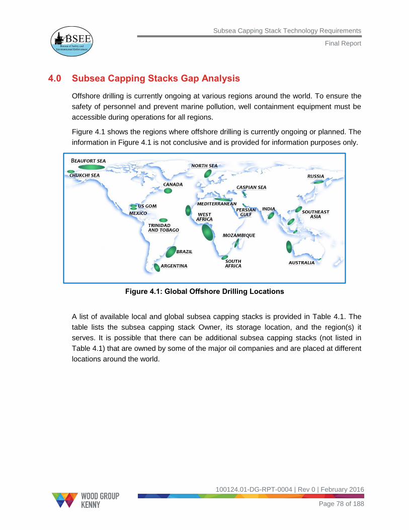
Subsea Capping Stack Technology Requirements
Final Report
100124.01-DG-RPT-0004 | Rev 0 | February 2016
Page 78 of 188
4.0 Subsea Capping Stacks Gap Analysis
Offshore drilling is currently ongoing at various regions around the world. To ensure the
safety of personnel and prevent marine pollution, well containment equipment must be
accessible during operations for all regions.
Figure 4.1 shows the regions where offshore drilling is currently ongoing or planned. The
information in Figure 4.1 is not conclusive and is provided for information purposes only.
Figure 4.1: Global Offshore Drilling Locations
A list of available local and global subsea capping stacks is provided in Table 4.1. The
table lists the subsea capping stack Owner, its storage location, and the region(s) it
serves. It is possible that there can be additional subsea capping stacks (not listed in
Table 4.1) that are owned by some of the major oil companies and are placed at different
locations around the world.

Subsea Capping Stack Technology Requirements
Final Report
100124.01-DG-RPT-0004 | Rev 0 | February 2016
Page 79 of 188
Table 4.1: Available Subsea Capping Stacks with Storage Locations and Serving Regions
Owner Subsea capping stack Storage Location Serving Region
MWCC
Subsea Containment Assembly
(SCA)
Ingleside, Texas GOM 15k psi subsea capping stack
10 k psi subsea capping stack
HWCG
15k psi subsea capping stack Houston, Texas
GOM
10k psi subsea capping stack Ingleside, Texas
OSPRAG OSPRAG subsea capping stack Aberdeen, Scotland UKCS
OSRL
15k psi subsea capping stack Norway
Worldwide (except U.S. waters)
15k psi subsea capping stack Brazil
10k psi subsea capping stack South Africa
10k psi subsea capping stack Singapore
WellCONTAINED
Aberdeen subsea capping stack Aberdeen, Scotland
Worldwide
Singapore subsea capping stack Singapore
Shell
Aberdeen subsea capping stack Aberdeen, Scotland Worldwide (Shell Operations
Only) Singapore subsea capping stack Singapore
Arctic subsea capping stack Alaska Arctic locations
(Shell Operations Only)
BP
Angola subsea capping stack Angola West Africa (BP Operations Only)
Houston subsea capping stack Houston, Texas For GOM but with global mission
(BP Operations Only)
For the GOM, there are five subsea capping stacks that are locally available and ready
to respond to a well control incident. In addition, two WellCONTAINED subsea capping
stacks, which are located outside of the U.S., can be used if needed. It is mandatory for
Operators drilling in the GOM to demonstrate access to a subsea capping stack and the

Subsea Capping Stack Technology Requirements
Final Report
100124.01-DG-RPT-0004 | Rev 0 | February 2016
Page 80 of 188
necessary expertise to control a blowout well. Currently, Operators rely on either of the
MWCC or HWCG subsea capping stacks to perform drilling activity in the GOM. Figure
4.2 shows the subsea capping stacks that can serve the GOM region only.
Figure 4.2: Subsea Capping Stacks that Serve the U.S. OCS
For the UKCS, there is one OSPRAG subsea capping stack that is stored in Aberdeen
and is local to the region. WellCONTAINED has a subsea capping stack in Aberdeen
that can serve globally. SWRP’s four subsea capping stacks can also be accessed, if
needed, to serve the UKCS. Overall, this region has access to seven subsea capping
stacks (one OSPRAG, two WellCONTAINED, and four SWRP).
No countries or regions outside of the U.S. and the U.K. have industry-led consortiums.
OSRL and WellCONTAINED subsea capping stacks are currently used by oil companies
outside the U.S. and the U.K. to respond to well control incidents. SWRP subsea
capping stacks serve all regions except U.S. waters, while WellCONTAINED subsea
capping stacks do not have that limitation. Figure 4.3 shows the storage locations of the
OSRL and WellCONTAINED subsea capping stacks.
Because of global availability, it can be said that there is a subsea capping stack for all
regions of the world. The caveat to this statement is that most of the companies do not
have access to a local subsea capping stack, and they depend on the consortiums that
own global capping solutions.
Global capping solutions have longer response times associated with transport from their
storage locations to the incident sites. In addition to air transport, subsea capping stacks
must be disassembled and reassembled, which adds to the response time. Long
response times have a significant impact on the recovery efforts because the longer

Subsea Capping Stack Technology Requirements
Final Report
100124.01-DG-RPT-0004 | Rev 0 | February 2016
Page 81 of 188
response times allow more hydrocarbons to release to the environment. Having subsea
capping stacks available in each country to quickly respond to a well control incident will
be beneficial.
Figure 4.3: Subsea Capping Stacks that Serve the World (except U.S. OCS)
Subsea Capping Stack Technology Requirements
Final Report
100124.01-DG-RPT-0004 | Rev 0 | February 2016
Page 82 of 188
5.0 Specifications, Standards, and Recommended Practices Applicable to Subsea Capping Stacks
5.1 Introduction
This section presents a review of proposed regulations, recommended practices (RPs),
specifications, and standards to evaluate the existing procedures for the design,
manufacture, and use of subsea capping stacks.
A subsea capping stack, which is a relatively new technology, is rapidly evolving in the
oil and gas industry. Currently, API RP 17W [3] is the only guidance available in the
industry. Because subsea capping stacks are built using components that are already
available and being used for subsea equipment (for example, BOPs and christmas
trees), the standards and guidelines that already exist for such equipment are used to
design subsea capping stacks.
5.2 API Specifications Relevant to Subsea Capping Stacks
5.2.1 API 16D – Specification for Control Systems for Drilling Well Control Equipment and Control Systems for Diverter Equipment
API Specification 16D [22] provides the design, manufacture, and installation
requirements for BOP stacks. It contains specifications for equipment that is common to
discrete hydraulic and EH/Multiplex (MUX) control systems for subsea BOP stacks. This
specification includes the accumulator and pump system requirements necessary to
meet the response times and redundancy needs of different equipment. The
specification also includes requirements for EDS systems and backup control systems.
According to API 16D, subsea BOP control systems must meet the following
requirements:
Closing response times are not to exceed 45 seconds for each ram BOP.
Closing response times for each annular BOP are not to exceed 60 seconds.
Operating responses for each choke and kill valve (either open or closed) are not to
exceed the minimum observed ram close response time.
The response time to unlatch the riser (LMRP) connector is not to exceed 45
seconds.
API 16D also provides a list of allowable functions for the optional EDS and the backup
control systems. ROV intervention is one of the backup control systems that is used to
shut in the well during an emergency scenario.

Subsea Capping Stack Technology Requirements
Final Report
100124.01-DG-RPT-0004 | Rev 0 | February 2016
Page 83 of 188
The ROV must be capable of unlocking the riser and wellhead connectors, along with
the following optional functions:
Close blind/shear rams
Close pipe rams
Open choke or kill valves
Close choke or kill valves
Accumulator discharge
Ram locking mechanisms
For a multi-function system, the subsea capping stack Owner may mount an operating
panel on a BOP stack in an accessible location with a clear label for identification using
ROV cameras. API Specification 16D also provides the maintenance procedure, periodic
inspection requirements, and relevant documentation for BOP stacks.
5.2.2 API 6A – Specification for Wellhead and Christmas Tree Equipment/ISO 10423
API Specification 6A [23] provides requirements and recommendations for the functional
interchangeability, design, materials, testing, inspection, welding, handling, storage, and
shipment of wellhead and christmas tree equipment. This specification applies to
connectors, fittings, casing and tubing hangers, valves and chokes, and wellhead
equipment.
All connectors, valves, chokes, and fittings in the subsea capping stack must conform to
this specification.
5.2.3 API 16A – Specification for Drill-through Equipment/ISO 13533
API Specification 16A [24] specifies requirements for performance, design, materials,
testing, inspection, and welding of drill-through equipment used for drilling. The
specification also defines the service conditions in terms of the pressure, temperature,
and wellbore fluids for which the equipment is designed.
API Specification16A establishes requirements for the following specific equipment:
Ram and annular BOPs
Ram blocks, packers, and top seals
Annular packing units
Drilling spools
Adapters
Loose connections
Clamps

Subsea Capping Stack Technology Requirements
Final Report
100124.01-DG-RPT-0004 | Rev 0 | February 2016
Page 84 of 188
5.2.4 API 17D – Design and Operation of Subsea Production Systems – Subsea Wellhead and Tree Equipment
API Specification 17D [25] provides specifications for subsea wellheads and
vertical/horizontal subsea trees. The specification also provides the associated tooling
necessary to handle, test, and install the equipment.
API Specification 17D includes specifications for the following equipment:
Subsea trees
Subsea wellheads
Mud line suspension systems
Drill-through mud line suspension systems
Tubing hanger systems
Miscellaneous equipment (for example, flanged end and outlet connections, clamp
hub-type connections, other end connections, studs, nuts, ring joint gaskets)
5.2.5 API 6AV1 – Specification for Validation of Wellhead Surface Safety Valves and Underwater Safety Valves for Offshore Service
API Specification 6AV1 [26] establishes requirements to verify:
Verify standard service Surface Safety Valve (SSV) and Underwater Safety Valve
(USV) design.
Verify the basic SSV/USV actuator design.
Demonstrate the verification testing covered by this specification, which is required
to qualify specific valve bore sealing mechanisms manufactured under API
Specification 6A for sandy service safety valves.
5.3 API Standard 53 – Blowout Prevention Equipment Systems for Drilling Wells
API Standard 53 [27] provides the requirements for installing and testing BOP equipment
systems on land and marine drilling rigs. This standard also includes the minimum
requirements for surface and subsea BOP stack classifications, pressure designations,
stack arrangements, and hydraulic control systems.
The main bore vertical closure device in the subsea capping stack must meet the closing
times specified in API Standard 53.

Subsea Capping Stack Technology Requirements
Final Report
100124.01-DG-RPT-0004 | Rev 0 | February 2016
Page 85 of 188
5.4 API Recommended Practices Relevant to Subsea Capping Stacks
5.4.1 API 17W – Recommended Practice for Subsea Capping Stacks
API RP 17W [3] provides recommended practices for the design, manufacture, and use
of subsea capping stacks and provides guidelines for the preservation, testing,
inspection, maintenance, and storage of subsea capping stacks.
5.4.1.1 Section 4
Section 4 of API RP 17W states that, at a minimum, the subsea capping stack:
Can monitor pressure below each vertical bore mechanical closure device.
Allows injection of the hydrate inhibitors and chemicals into the main vertical bore
below the vertical outlets.
Contains one or more outlets for diverting flow and/or pumping kill fluid into the main
vertical bore.
In addition, the subsea capping stack must:
Inject kill fluids into the wellbore.
Facilitate monitoring of critical wellbore parameters (for example, pressure and
temperature).
Contain standardized interfaces on all inlets and outlets.
Section 4 also details the interface descriptions, design, and functional requirements (for
example, service conditions, component design, flow isolation barriers).
For subsea capping stacks built with a global perspective, all materials that come in
contact with the well fluids must meet the requirements of NACE MR0175 for sour
service. NACE MR0175 was developed for the prevention of sulfide stress cracking
caused by hydrogen sulfide (H2S) in the oil and gas production systems (refer to Section
4.4.7.4 Sour Service of API RP 17W).
5.4.1.2 Section 5
Section 5 of API RP 17W provides a list of steps for using a subsea capping stack.
The list includes:
Initial actions.
Equipment notification and callout.
Well condition assessment.
Subsea capping stack deployment.

Subsea Capping Stack Technology Requirements
Final Report
100124.01-DG-RPT-0004 | Rev 0 | February 2016
Page 86 of 188
5.4.1.3 Section 6
Section 6 of API RP 17W provides details of the various tests (such as function tests,
pressure tests), maintenance schedules, inspection plans, and preservation and the
protection of elastomeric materials, fluids, and spare parts from environmental effects.
API RP 17W refers to other standards and specifications (such as API Standard 53 [27],
API Specification 6A [23], API Specification17D [25], API Specification16A [24], and
API RP 17H [6]) for the design and use of various components of a subsea
capping stack).
5.4.2 API 17H – Recommended Practice for Remotely Operated Vehicle (ROV) Interfaces on Subsea Production Systems
API RP 17H [6] provides design recommendations for subsea intervention systems and
ROV interfaces. The different interfaces provided are rotary (for example, low-torque)
interface, rotary docking, linear (such as push) interfaces, different types of hot stab
hydraulic connections, and component change-out interfaces. In addition, API RP 17H
provides recommendations for typical dimensions that can be assumed for access
validation, minimum elevation of ROV interface above seabed, and ROV stabilization
methods during the intervention tasks. This recommended practice also provides the
features and dimensions of different types of hot stabs and receptacles that can be used
to override existing systems and complement systems, including lower riser packages
with locking and unlocking functions, hydraulically activating valves and tools, and more.
The subsea capping stack hydraulic functions are fitted with API RP 17H ROV hot stab
receptacles. The rams used as vertical main bore closure devices must close in less
than 45 seconds to meet the API Standard 53 closing time requirements and must be
fitted with API RP 17H Type C (such as high flow) hot stab devices with external
locking devices.
5.4.3 API 17G – Recommended Practice for Completion/Workover Risers
API RP 17G [28] provides requirements and recommendations for the design, analysis,
materials, fabrication, testing, and operation of subsea completion/workover riser
systems run from a floating vessel.
API RP 17G includes specifications for the following equipment:
Riser joints
Connectors
Workover control systems
Surface flow trees

Subsea Capping Stack Technology Requirements
Final Report
100124.01-DG-RPT-0004 | Rev 0 | February 2016
Page 87 of 188
Surface tree tension frames
Lower workover riser packages
Lubricator valves
Retainer valves
Subsea test trees
Shear subs
Tubing hanger orientation systems
Swivels, annulus circulation hoses, riser spiders, umbilical clamps, handling and test
tools, and tree cap running tools

Subsea Capping Stack Technology Requirements
Final Report
100124.01-DG-RPT-0004 | Rev 0 | February 2016
Page 88 of 188
6.0 U.S and Global Regulations Available for Subsea Capping Stacks
6.1 Introduction
This section assesses the capping solutions and regulations that are in place for
countries which are members of the International Regulators Forum (IRF). A review of
the active and proposed U.S. regulations related to well control and containment
equipment is included.
Currently, there are no specific Code of Federal Regulations (CFRs) in place in the U.S.
for subsea capping stacks. Notice to Lessees and Operators (NTL) number 2010-N10
[29] states that Operators must provide adequate information demonstrating that they
can access and deploy a containment system during a blowout or other loss of well
control.
6.2 International Regulators Capping Solutions
6.2.1 Australian Capping Solution
Currently, Australia does not have regulations that are specific to subsea capping stacks.
Australia has no local subsea capping stack and depends on the four OSRL subsea
capping stacks. The closest and most preferred subsea capping stack is the one in
Singapore. Some of the Australian companies are members of WellCONTAINED and
use the WellCONTAINED subsea capping stacks.
To perform a drilling activity, the National Offshore Petroleum Safety and Environmental
Management Authority (NOPSEMA) must approve the Well Operations Management
Plan. The Plan must satisfy the regulator requirements that the plan is appropriate for
the nature and scale of the well activity and that it shows the risks identified as they
relate to well activities. These identified risks are to be managed by sound engineering
principles, standards, specifications, and good oilfield practice.
A consortium of 12 oil and gas companies operating in Australian waters (Apache, BP,
BHP Billiton Petroleum, Chevron, ConocoPhillips, ENI, ExxonMobil, INPEX, PTT
Exploration and Production [PTTEP], Santos, Shell, and Woodside) have committed to
the development of an Australian component of the Well Capping and Containment
Solution, called the Subsea First Response Toolkit (SFRT).
The Australian Marine Oil Spill Centre (AMOSC) owns the SFRT on behalf of the
industry, with Oceaneering providing the equipment and expertise for mobilization and
deployment. The SFRT is designed to fit on any work class ROV and can also enable

Subsea Capping Stack Technology Requirements
Final Report
100124.01-DG-RPT-0004 | Rev 0 | February 2016
Page 89 of 188
the application of subsea dispersant where there is a need to make the surface safe
for work.
The SFRT, which is located in Australia, contains all specialized equipment necessary to
enable the wellhead and the surrounding area, including the seabed, to be cleaned up
and made safe for the installation of a capping device. All Australian offshore petroleum
Operators will have access to the toolkit on an affordable basis.
Tasks performed by the SFRT include:
Speciality ROV tasks
Intervention on existing BOPs and operate them hydraulically
Surveys, mapping, and video recordings
Setting of sonar arrays for equipment guidance during deployment
Application of subsea dispersant at the well
Clearing of debris from the wellhead area
The time to mobilize a global subsea capping stack is anticipated to be approximately 9
to 11 days. However, a subsea capping stack cannot be deployed on the wellhead/BOP
of the incident site until the site has been cleared and made safer. The time to prepare
the well for a subsea capping stack is estimated to be 14 to 21 days. Therefore, by the
time the incident site is cleared, the global subsea capping stack will reach the incident
well location and be ready for deployment.
NOPSEMA Environmental Guidance Note, N-04700-GN0940, Rev. 2, July 2012 [30]
provides the roles and responsibilities of the petroleum Operator and NOPSEMA during
a well control incident.
6.2.2 Canadian Capping Technology
The Canadian Environmental Assessment Agency is considering the following potential
conditions for recommendation to the Minister of Environment for inclusion in a Decision
Statement under the Canadian Environmental Assessment Act, 2012. [31]:
The Operator must present all reasonable measures to prevent accidents and
malfunctions that can result in adverse environmental effects and must implement
appropriate emergency response procedures and contingency plans to the
satisfaction of the Canada-Nova Scotia Offshore Petroleum Board (CNSOPB).
The Operator must prepare an Oil Spill Response Plan and a Well Containment
Plan in accordance with CNSOPB requirements and submit the plan for approval at
least 90 days before drilling.

Subsea Capping Stack Technology Requirements
Final Report
100124.01-DG-RPT-0004 | Rev 0 | February 2016
Page 90 of 188
The Oil Spill Response Plan must include:
Procedures to respond to an oil spill (for example, oil spill containment, oil
recovery).
Measures for wildlife response, protection, and rehabilitation (for example,
collect and clean marine mammals, birds, and sea turtles) and for shoreline
protection and clean-up, which are to be developed in consultation
with CNSOPB.
Procedures to notify CNSOPB and other relevant regulatory agencies of the
occurrence of any oil spill as soon as possible.
The Operator must conduct an exercise of the oil spill response before beginning
project activities.
The Well Containment Plan must include:
A Relief Well Contingency Plan.
A Well Capping Plan describing the plan to mobilize and deploy a subsea
capping stack, if required.
In the event of an incident, the Operator must implement the Oil Spill Response Plan
and the Well Containment Plan.
In an effort to develop a capping solution for Canada, Waterford Energy Services Inc.
(WESI) formed a joint venture company with Trendsetter Engineering to serve the
Canadian offshore market in the areas of subsea solutions, drilling, completions, and
well control.
The joint venture company provides the Canadian offshore market with a subsea
capping stack and containment solution, subsea trees, manifolds, and related
equipment. They have developed the First Response Well Containment System for
Canada, which uses equipment and technology located in Newfoundland and Labrador
to provide immediate and local response to an offshore incident.
Currently, no local subsea capping stack is available in Canada.
6.2.3 Norway Capping Solution
In Norway, the Petroleum Safety Authority (PSA) has the regulatory responsibility for
safety, emergency preparedness, and the working environment for all offshore and
onshore petroleum-related activities.
Norway does not have a local consortium that owns subsea capping stacks to serve the
Norwegian region. They depend on the global capping solutions from OSRL and
WellCONTAINED. One of the OSRL subsea capping stacks is stored in Norway. In June
2013, Norway updated the NORSOK Standard D010 – Well Integrity in Drilling and Well

Subsea Capping Stack Technology Requirements
Final Report
100124.01-DG-RPT-0004 | Rev 0 | February 2016
Page 91 of 188
Operations document [32]. NORSOK Standard D-010 includes the plans for the capping
and containment of a blowing subsea well and the plans for drilling a relief well.
6.2.4 U.K. Capping Solution
The U.K. has no specific regulations concerning subsea capping stacks. The U.K. has
access to the local OSPRAG subsea capping stack, which is stored in Aberdeen,
Scotland. In addition, it also has access to the OSRL and WellCONTAINED global
subsea capping stacks.
6.2.5 Brazil Capping Solution
No information is available on subsea capping stack regulatory requirements for Brazil.
Similar to Norway, Brazil does not have a local consortium that owns subsea capping
stacks. Brazil depends on the global capping solutions from OSRL and
WellCONTAINED. One of the OSRL subsea capping stacks is stored in
Angra dos Reis, Brazil.
6.2.6 New Zealand Capping Solution
New Zealand operates within a goal setting regime where there is rarely any specific
legislation on particular technologies such as subsea capping stacks.
Operators must submit a Discharge Management Plan to Maritime New Zealand (MNZ)
before starting drilling operations. The Well Control Contingency Plan (WCCP) section of
the Discharge Management Plan has a contingency plan that the Operator must follow in
a worst-case scenario. MNZ approves the Discharge Management Plan only if the
Operator has procedures in place that will prevent or mitigate the environmental impacts
from an accidental loss.
If a significant oil spill occurs, MNZ’s Marine Pollution Response Service is New
Zealand’s lead national oil spill response agency. It is responsible for maintaining a
nationwide capability to respond to marine oil spills through comprehensive national and
international agreements.
6.2.7 Denmark, Mexico, and the Netherlands Capping Solution
There is no information available on regulatory requirements for capping solutions in
Denmark, Mexico, or the Netherlands.

Subsea Capping Stack Technology Requirements
Final Report
100124.01-DG-RPT-0004 | Rev 0 | February 2016
Page 92 of 188
Denmark, Mexico, and the Netherlands depend on the global OSRL and
WellCONTAINED subsea capping stacks. There are no local subsea capping stacks
dedicated to this region. Pemex is working with BP to provide a subsea capping stack
solution for Mexico.
Currently, most of the oil and gas companies are justifying their contingency plans with
the regulators by using global subsea capping stack systems on a case-by-case basis.
This has advantages in terms of cost and standardization of tools and equipment, but the
details of mobilization, staging, assembly, testing, and installation vary from one location
to another.
6.3 Current U.S. Regulations – 30 CFR 250
The BSEE website (www.bsee.gov) directs users to the Electronic Code of Federal
Regulations (E-CFR) webpage (www.ecfr.gov), where the current regulations are placed
and updated periodically [33].
On the E-CFR webpage, the regulations for Blowout Preventer (BOP) systems and well
control are provided under Title 30 Chapter II Subchapter B Part 250 (referred to
as 30 CFR 250). Part 250, which is named Oil and Gas and Sulphur Operations in the
Outer Continental Shelf, provides information on the plans and includes requirements for
oil and gas drilling, well control, well completion, workover, production, and
decommissioning operations. A complete list of subparts with CFR numbering and titles
is provided in Table 6.1.

Subsea Capping Stack Technology Requirements
Final Report
100124.01-DG-RPT-0004 | Rev 0 | February 2016
Page 93 of 188
Table 6.1: The BSEE 30 CFR 250 Subparts List
Subpart CFR Numbering Title of Subpart
A §250.101 General
B §250.200 Plans and Information
C §250.300 Pollution Prevention and Control
D §250.400 Oil and Gas Drilling Operations
E §250.500 Oil and Gas Well-Completion Operations
F §250.600 Oil and Gas Well-Workover Operations
H §250.800 Oil and Gas Production Safety Systems
I §250.900 Platforms and Structures
J §250.1000 Pipelines and Pipeline Rights-of-Way
K §250.1150 Oil and Gas Production Requirements
L §250.1200 Oil and Gas Production Measurement, Surface Commingling, and
Security
M §250.1300 Unitization
N §250.1400 Outer Continental Shelf Civil Penalties
O §250.1500 Well Control and Production Safety Training
P §250.1600 Sulphur Operations
Q §250.1700 Decommissioning Activities
S §250.1900 Safety and Environmental Management Systems (SEMS)
Subpart D provides the requirements for oil and gas drilling operations. Sections 250.440
to §250.451 (Blowout Preventer [BOP] System Requirements) provide the minimum
requirements for a surface BOP system, subsea BOP system, and associated
equipment. The BOP maintenance, inspection, testing, and recordkeeping requirements
are provided in this section of the regulations.
According to §250.442, anyone who drills with a subsea BOP system must:
Have at least four remote-controlled, hydraulically operated BOPs (at least one
annular preventer, two pipe rams, and one blind shear ram).
Have an operable dual-pod control system to ensure proper and independent
operation of the BOP system.
Have an accumulator system to provide fast closure of all BOP components and to
operate all critical functions in case of a loss of the power fluid connection to the
surface. The closing time must meet the API RP 53 response times.

Subsea Capping Stack Technology Requirements
Final Report
100124.01-DG-RPT-0004 | Rev 0 | February 2016
Page 94 of 188
Have a subsea BOP stack that is equipped with ROV intervention capability. At a
minimum, the ROV must be capable of closing one set of pipe rams, closing one set
of blind shear rams, and unlatching the LMRP.
Provide Autoshear and Deadman systems for dynamically positioned rigs.
Clearly label all control panels for the subsea BOP system.
Establish the minimum requirements for personnel authorized to operate critical
BOP equipment.
§250.443 states that all BOP systems must include the following associated systems
and related equipment:
An automatic backup to the primary accumulator charging system. The power
source must be independent from the primary accumulator power source. The
independent power source must have sufficient capability to close and hold closed
all BOP components.
At least two BOP control stations. One station must be on the drilling floor. The other
station must be located in a location that is readily accessible from the drilling floor.
Side outlets on the BOP stack for separate choke and kill lines. If the stack does not
have side outlets, a drill spool with side outlets must be installed.
Both choke and kill lines must have two full-opening valves and must be
remote-controlled. The choke line must be installed above the bottom ram. The kill
line may be installed below the bottom ram.
Section 250.446 provides the following BOP maintenance and inspection requirements:
The BOP maintenance and inspection must ensure that the equipment functions
properly. The BOP maintenance and inspection must exceed the provisions
described in API RP 53.
The subsea BOP and marine riser must be visually inspected at least once every
three days if weather and sea conditions permit.
Sections 250.447, 250.448, and 250.449 provide the following BOP testing
requirements:
Pressure testing must be performed on the BOP system (this includes the choke
manifold, kelly valves, inside BOP, and drill string safety valve).
A low pressure and high pressure test must be conducted for each BOP component.
The low pressure test must be conducted before the high pressure test. Each
individual pressure test must hold the required pressure for 5 minutes.

Subsea Capping Stack Technology Requirements
Final Report
100124.01-DG-RPT-0004 | Rev 0 | February 2016
Page 95 of 188
A stump test of the subsea BOP system must be performed before installation.
Annular and ram BOPs must be function tested every seven days between
pressure tests.
Section 250.450 provides the recordkeeping requirements for BOP tests.
Similar to Subpart D, Subparts E, F, and Q also provide the requirements for BOP
systems and associated equipment. The current regulations repeat similar BOP
requirements in multiple locations (drilling, completion, workover, and decommissioning)
throughout 30 CFR 250. The Proposed Rule for well control (refer to Section 6.5.2)
consolidates the common BOP requirements into one location.
6.4 Current Notice to Lessees and Operators Related to Well Control
The BSEE issued Notices to Lessees and Operators (NTLs) to clarify, supplement, or
provide more details about regulatory requirements under 30 CFR 250 – Oil and Gas
and Sulphur Operations in the Outer Continental Shelf. Following the Macondo incident,
BSEE issued two NTLs to request additional information from Operators to approve the
APD. The two NTLs were NTL 2010-N06 and NTL 2010-N10.
6.4.1 NTL 2010-N06
This NTL provides the information requirements for Exploration Plans (EP)16 and
Development Operations Coordination Documents (DOCD)17 on the OCS. In accordance
with this NTL, the Operator must submit information with the EP, the DOCD, or as a
supplement to a previously submitted plan. The information required to be submitted to
BSEE as part of the APD includes [34]:
A scenario of a potential blowout that is expected to have the highest volume of
liquid hydrocarbons for the proposed well to be included in the EP or
DOCD document.
Estimated flow rate, total volume, and maximum duration of the potential blowout.
The potential for a well to bridge over, the likelihood for surface intervention to stop
the blowout, the availability of a rig to drill a relief well, and rig package constraints.
16
Exploration Plan (EP) describes all exploration activities planned by an Operator for a specific lease(s), the timing of these activities, information concerning drilling vessels, the location of each well, and an analysis of both offshore and onshore impacts that may occur as a result of the plan’s implementation.
17 A Development Operations Coordination Document (DOCD) is a plan that describes development and
production activities proposed by an Operator for a lease or a group of leases. The description includes the timing of these activities, information concerning drilling vessels, the location of each proposed well or production platform or other structure, and an analysis of both offshore and onshore impacts that may occur as a result of the plan’s implementation.

Subsea Capping Stack Technology Requirements
Final Report
100124.01-DG-RPT-0004 | Rev 0 | February 2016
Page 96 of 188
The time it would take to contract for a rig, move it onsite, and drill a relief well,
including the possibility of drilling a relief well from a neighboring platform or an
onshore location.
Assumptions and calculations that are used to determine the volume of a worst case
discharge scenario.
All assumptions made concerning:
The well design, reservoir characteristics, fluid characteristics, and Pressure
Volume Temperature (PVT) characteristics.
Any analog reservoirs considered in making those assumptions.
An explanation of reasons for using those analog reservoirs.
The supporting calculations and models used to determine the daily discharge
rate possible from the uncontrolled blowout portion of the worst case discharge
scenario for both proposed or approved EP or DOCD and the proposed or
approved Oil Spill Response Plan (OSRP)18.
Proposed measures that would enhance the ability to prevent a blowout, to reduce
the likelihood of a blowout, and to conduct effective and early intervention in the
event of a blowout, including arrangements for drilling relief wells.
6.4.2 NTL 2010-N10
According to this NTL, Operators using subsea BOPs or surface BOPs on floating
facilities must submit sufficient information to BSEE demonstrating that they have access
to and can deploy surface and subsea containment resources that are adequate to
promptly respond to a blowout or loss of well control [29].
The Bureau of Ocean Energy Management (BOEM) will evaluate whether Operators
have provided adequate information in their current OSRPs describing the types and
quantities of surface and subsea containment equipment that the Operator can access in
the event of a spill or threat of spill, and the deployment time for each. The types of
information the BOEM will evaluate include, but are not limited to:
Subsea containment and capture equipment, including containment domes and
subsea capping stacks.
Subsea utility equipment, including hydraulic power, hydrate control, and dispersant
injection equipment.
Riser systems.
ROVs.
18
OSRPs for the offshore oil and gas exploration, production, and transportation (pipeline) industry are regulated in the U.S. by BSEE regulations according to 30 CFR Part 254.

Subsea Capping Stack Technology Requirements
Final Report
100124.01-DG-RPT-0004 | Rev 0 | February 2016
Page 97 of 188
Capture vessels.
Support vessels.
Storage facilities.
6.5 Regulation in Development
6.5.1 Proposed Arctic Drilling Rule
In February 2015, the Department of the Interior (DOI), acting through the BSEE and the
BOEM, proposed to revise and add new requirements to regulations for exploratory
drilling and related operations on the OCS seaward of the State of Alaska (Alaska OCS).
The proposed rule is designed to ensure safe, effective, and responsible exploration of
the Arctic OCS (Beaufort Sea and Chukchi Sea Planning Areas) oil and gas resources
while protecting the marine, coastal, and human environments; Alaska Natives cultural
traditions; and access to subsistence resources [35].
This proposed rule will add to and revise existing regulations in 30 CFR Parts 250, 254,
and 550 for Arctic oil and gas activities. The proposed rule focuses on Arctic OCS
exploratory drilling activities that use Mobile Offshore Drilling Units (MODUs) and related
operations during the Arctic OCS open-water drilling season19. This proposed rule
addresses a number of important issues and objectives, ensuring that each Operator:
Designs and conducts exploration programs in a manner suitable for Arctic OCS
conditions.
Develops an Integrated Operations Plan (IOP)20 that addresses all phases of its
proposed Arctic OCS exploration program and submits the IOP to BOEM at least 90
days in advance of filing the Exploration Plan.
Has access to, and the ability to promptly deploy, Source Control and Containment
Equipment (SCCE) while drilling below, or working below, the surface casing.
Has access to a separate relief rig so that it can timely drill a relief well in the event
of a loss of well control under the conditions expected at the site.
Has the capability to predict, track, report, and respond to ice conditions and
adverse weather events.
19
The Arctic open-water drilling season is typically only 3 – 4 months long and can be much shorter in a given year or be shortened by mid-season ice intrusions. It starts around late June and ends early November. 20
The purpose of the IOP is to describe, at a strategic or conceptual level, how exploratory drilling activities will be designed, executed, and managed as an integrated endeavor from start to finish.

Subsea Capping Stack Technology Requirements
Final Report
100124.01-DG-RPT-0004 | Rev 0 | February 2016
Page 98 of 188
Effectively manages and oversees contractors.
Develops and implements an OSRP that is designed and executed in a suitable
manner for the unique Arctic OCS operating environment and has the necessary
equipment, training, and personnel for oil spill response on the Arctic OCS.
This proposed rule requires that when the Operator uses a Mobile Offshore Drilling Unit
(MODU) to drill below or work below the surface casing, the Operator must have:
Access to a subsea capping stack that is positioned to arrive at the well within 24
hours after a loss of well control.
A cap and flow system and a containment dome that are positioned to arrive at the
well within 7 days after a loss of well control.
6.5.2 Proposed Well Control Rule
In April 2015, the BSEE proposed new regulations to consolidate equipment and
operational requirements that are common to other subparts pertaining to offshore oil
and gas drilling, completions, workovers, and decommissioning.
The proposed rule [36]:
Focuses on the BOP requirements, including incorporation of industry standards
and revising existing regulations.
Includes reforms in areas of well design, well control, casing, cementing, real time
well monitoring, and subsea containment.
Addresses and implements multiple recommendations resulting from various
investigations of the Macondo incident
Incorporates guidance from several NTLs and revised provisions related to drilling,
workover, completion, and decommissioning operations to enhance safety and
environmental protection.
After the Macondo incident, BSEE issued NTLs for source control and containment
requirements during drilling operations. The information in the NTLs was included as part
of the new proposed regulations.
In accordance with the proposed Well Control Rule, the Source Control and Containment
Requirements will be placed in §250.462 of 30 CFR 250. The proposed rule will include
five paragraphs:
1. The first paragraph requires Operators to determine their source control and
containment capabilities by evaluating the performance of the well design to
determine whether full shut-in can be achieved without reservoir fluids broaching the
seafloor. Based on this evaluation, if the well can only be partially shut in, Operators

Subsea Capping Stack Technology Requirements
Final Report
100124.01-DG-RPT-0004 | Rev 0 | February 2016
Page 99 of 188
are required to establish their ability to flow and capture any residual fluids to a
surface production and storage system.
2. The second paragraph requires Operators to have access to, and the ability to
deploy, the SCCE necessary to regain control of the well.
3. The third paragraph requires the Operator to submit a description of the source
control and containment capabilities before BSEE will approve the APD. The
submittal to the Regional Supervisor must include:
a. The source control and containment capabilities for controlling and containing a
blowout event at the seafloor
b. A discussion of the determination required in the first paragraph
c. Information showing that the Operator has access to, and the ability to deploy,
all equipment necessary to regain control of the well
4. The fourth paragraph requires that Operators contact the District Manager and
Regional Supervisor for re-evaluation of the source control and containment
capabilities if there are any well design changes or if any of the approved SCCE is
out of service.
5. The fifth paragraph outlines the maintenance, inspection, and testing requirements
of certain identified containment equipment as provided in Table 6.2.

Subsea Capping Stack Technology Requirements
Final Report
100124.01-DG-RPT-0004 | Rev 0 | February 2016
Page 100 of 188
Table 6.2: SCCE Proposed Testing Requirements [36]
Equipment Requirements Additional information
(1) Subsea capping stacks (i) Function test all pressure holding
critical components on a
quarterly frequency (not to
exceed 104 days)
Pressure holding critical components
are those components that will
experience wellbore pressure during
a shut-in after being functioned.
(ii) Pressure test pressure holding
critical components on a bi-
annual basis, but no later than
210 days from the last pressure
test. All pressure testing must be
witnessed by BSEE and a BSEE-
approved verification
organization,
Pressure holding critical components
are those components that will
experience wellbore pressure during
a shut-in. These components
include, but are not limited to, all
blind rams, wellhead connectors,
and outlet valves.
(iii) Notify BSEE at least 21 days
prior to commencing any
pressure testing.
(2) Production safety
systems used for flow
and capture operations
(iv) Meet or exceed the requirements
set forth in 30 CFR Subpart H,
§250.800 through §250.808.
(v) Have all equipment unique to
containment operations available
for inspection at all times.
(3) Subsea utility equipment Have all equipment unique to
containment operations available for
inspection at all times,
Subsea utility equipment includes,
but is not limited to, hydraulic power
sources, debris removal, hydrate
control equipment, and dispersant
injection equipment.

Subsea Capping Stack Technology Requirements
Final Report
100124.01-DG-RPT-0004 | Rev 0 | February 2016
Page 101 of 188
7.0 Subsea Capping Stack Design Considerations
7.1 Introduction
The design of a subsea capping stack is affected by factors such as the service
environment, preservation environment, component design, transportation, and post-
installation functionality requirements.
Design load analysis, fatigue modeling, and flow analysis must be performed to verify:
The structural integrity of the wellbore to sustain the subsea capping stack loads.
The ability of the wellbore to sustain shut-in or contained flow pressures.
7.2 Service Conditions
Service conditions refer to the pressure, temperature, material classification, and other
operating conditions for which the equipment is designed. High concentrations of solids
in well fluids can increase the erosion and are considered in the design of the subsea
capping stack.
7.2.1 Pressure Rating
Working pressure ratings of all subsea capping stacks must conform to industry
standards set by API RP 17G, Section 8.
The available subsea capping stacks are rated to 10,000 psi or 15,000 psi.
7.2.2 Temperature Rating
API RP 17G specifies the temperature classification in which subsea capping stacks are
designed to operate. Typically, the minimum temperature is the lowest ambient
temperature the equipment is subjected to during operation, transportation, and
preservation. The maximum temperature is encountered during flowing conditions.
According to API RP 17W, the minimum classification for pressure-containing and
pressure-controlling materials should be a temperature classification of U (0°F [-18C] to
250°F [121C]). API RP 17G also provides information for the design and rating of
equipment for use at elevated temperatures.
The MWCC 15,000-psi subsea capping stack is the only one that is rated to a
temperature of 350F.

Subsea Capping Stack Technology Requirements
Final Report
100124.01-DG-RPT-0004 | Rev 0 | February 2016
Page 102 of 188
7.2.3 Water Depth Rating
In accordance with API RP 17W, the subsea capping stack Basis of Design (BOD) must
include the range and maximum operating depth for its application. The subsea capping
stacks manufactured with a global perspective are rated to at least 10,000 ft.
The subsea capping stacks designed for the Arctic have different design requirements
because they are designed for shallow waters (< 500 ft.) and low temperatures (-40F).
Currently, only one Arctic subsea capping stack (owned by Shell) is available.
7.2.4 Flow Capacity
The maximum flow capacity of a subsea capping stack is limited by the lesser of the
following two parameters:
Acceptable limit of erosion within the subsea capping stack
Acceptable pressure drop within the subsea capping stack components
The flow from an incident well can have high concentrations of solids and can cause
erosion of the subsea capping stack components. The subsea capping stack design
should be analyzed using Computational Fluid Dynamics (CFD) to determine the areas
of erosion. Critical erosion areas should be designed and tested in accordance with API
Specification 6AV1 Class II for sandy service.
7.3 Interface Descriptions
Mechanical interface connections on any subsea capping stack are typically
multifunctional and must interface with a variety of rig and vessel running tools and
containment connection systems. The interface information must be documented and
planned prior to any incident requiring the use of a subsea capping stack.
7.3.1 Attachment to Incident Well
The attachment point is mostly a user-defined, industry-recognized connection that
conforms to the standards of API Specification 6A for Flange Connections and API RP
17G for Other Connections. The attachment is performed using an actuated hydraulic
wellhead-style connector provided at the bottom of the subsea capping stack.
The subsea capping stack attachment point depends on the condition of the well. The
three most likely subsea capping stack attachment points, which are listed in the
recommended order of preference, are:
1. Top of the lower BOP mandrel – accessible if the LMRP is removed
2. Subsea wellhead – accessible if the BOP is removed

Subsea Capping Stack Technology Requirements
Final Report
100124.01-DG-RPT-0004 | Rev 0 | February 2016
Page 103 of 188
3. Riser adapter above the LMRP – accessible if the marine riser is removed
Figure 7.1 provides the typical connection points of the subsea capping stack to the
incident well. The connection interface between the BOP and the LMRP may not match
the wellhead and tree profile. Therefore, the subsea capping stack Owner provides
additional interfacing tools (for example, adapter spools, spacer spools) with the subsea
capping stack to maintain a connection with the incident well, depending on the situation.
Figure 7.1: Typical Subsea Capping Stack Attachment Points [3]

Subsea Capping Stack Technology Requirements
Final Report
100124.01-DG-RPT-0004 | Rev 0 | February 2016
Page 104 of 188
7.3.2 Attachment of External Flow Paths
External flow equipment such as jumpers, manifolds, and risers, may interfere with the
subsea capping stack for bullheading and killing the well or for flowing the incident well
to a containment system. The attachment can be based on the flowline connection or hot
stab technologies using an ROV. In either case, industry standard connections must be
used to allow for maximum flexibility during the subsea capping incident.
It is possible that the flowline connection points and high flow hot stabs provided by
subsea equipment vendors are proprietary in nature and are not convertible to a
universal standard type. Therefore, subsea capping stack Owners must have the
necessary connection equipment (for example, goosenecks, rigid jumpers, pressure
caps, hot stabs, running tools) to connect the subsea capping stack to the intended
containment system.
7.3.3 Attachment Interface at the Top of the Subsea Capping Stack
Depending on the requirements at the incident well, the top of the subsea capping stack
may be connected to an additional subsea capping stack (or secondary cap) or to a
containment system. For this reason, the top mandrel interface of the subsea capping
stack must:
Be pressure-containing.
Be rated to the full working pressure of the subsea capping stack.
Allow for attachment to the subsea hydraulic connector.
For single ram subsea capping stacks, the cap on the top interface acts as the
secondary barrier. For dual ram subsea capping stacks, it is the tertiary barrier. The
attachment interface at the top of the subsea capping stack must be an
industry-recognized connection and must conform to API Specification 6A for Flange
Connections and API RP 17G for Other Connections.
7.3.4 External Controls and Monitoring
An ROV primarily controls the subsea capping stacks. Data monitoring is also performed
with ROV intervention using ROV-readable gauges.
7.4 Connectors
According to API RP 17W, the material and testing of all subsea capping stack
connectors must conform to the relevant sections of API Specification 6A and
API Specification 17D.

Subsea Capping Stack Technology Requirements
Final Report
100124.01-DG-RPT-0004 | Rev 0 | February 2016
Page 105 of 188
7.4.1 Wellhead Connector
The subsea capping stack has a hydraulically actuated wellhead connector that
interfaces with the incident well. The connectors must conform to the maximum standard
pressure rating according to API RP 17G.
7.4.2 Flowline Connector
‘Cap and flow’ subsea capping stacks require flowline connector systems. The flowline
connector must have API standard flange interface on the flow spool outlets and
downstream of any chokes.
7.4.3 Diversion Outlet Connection
The diversion outlet connection components must be industry standard size with rated
working pressures in accordance with API RP 17G. The diversion outlets must be placed
in a symmetrical configuration to minimize asymmetric thrust forces.
7.4.4 Fluid Injection Inlet Connections
The fluid injection inlet connection must be designed to the same specifications as the
diversion outlet connection.
7.4.5 Dispersants, Chemicals, and Hydrate Injections
The design of subsea capping stacks includes chemical injection inlets. In accordance
with API RP 17W, the subsea capping stack Manufacturer must design the inlets (such
as number and size) in accordance with the chemical dispersant, and the hydrate
inhibitor capacity. The optimum placement of inlets must be identified to enable efficient
mixing.
7.5 Control System
For subsea capping stack control systems, API 16D, API RP 17G, and API Standard 53
ensure industry best practices, commonality of interfaces, fast closure of barrier devices,
and the control of cap and flow scenario functions.
The subsea capping stack must provide fast closure of all barrier devices for the
applicable water depths of the main bore and diversion outlets in accordance with API
Standard 53. Surface control of the subsea capping stack with direct hydraulic power
may be appropriate for subsea wells in shallow water. As the water depth increases,
hydraulic flow rates, umbilical size and handling, and overall hydraulic response time
may impair the performance of the subsea capping stack.

Subsea Capping Stack Technology Requirements
Final Report
100124.01-DG-RPT-0004 | Rev 0 | February 2016
Page 106 of 188
The major items that must be considered when designing a subsea capping stack
control system are:
Water depth of the intended operation
Hydraulic fluid volumes to repeat component functions
Function speed of closure devices
ROV accessibility and visibility
Flexibility to work within a variety of operating conditions
Proximity to wellbore flow outlets
The control system must have the hydraulic capacity to perform functions such as
operating the well connector, the main bore, and the diversion outlet closure devices.
The hydraulic control system must have the ability to recharge while operating subsea.
To reduce the size and weight of the subsea capping stack equipment, alternative
sources or types of hydraulic fluid accumulation may be designed for the subsea
capping stack.
The main bore vertical closure device (such as BOP rams or gate valves) used in a
subsea capping stack must function quickly within the component’s recommended
maximum closing speed and no slower than that specified in API Standard 53.
The subsea capping stack hydraulic functions must be fitted with standard API RP 17H
hot stab receptacles and must meet the API Standard 53 timing requirements. Figure 7.2
and Figure 7.3 show a Type C receptacle and a hot stab with an external
locking mechanism.
The rams used as the vertical main bore closure device must be fitted with API RP 17H
Type C (such as high flow) hot stab devices with external locking devices and must be
clearly marked and labeled:
On the equipment.
On the subsea capping stack drawings and documentation.

Subsea Capping Stack Technology Requirements
Final Report
100124.01-DG-RPT-0004 | Rev 0 | February 2016
Page 107 of 188
Figure 7.2: API RP 17H Type C Receptacle
Figure 7.3: API RP 17H Type C, Hot Stab (High Flow)
Subsea capping stack interface components and gauges must be located within the
normal view of the ROV camera. In accordance with API RP 17H, adequate ‘grab
handles’ should be available to enable the ROV to remain stationary for engaging the
interface item (such as hot stab) in adverse current conditions. For ROV-operated
functions, the required operating torque should conform to API RP 17H.
7.6 Flow Isolation Barriers
A variety of closure devices are used to provide isolation under flowing conditions. The
subsea capping stack Manufacturer must ensure that the closure device is qualified to
shut in a flowing gas and a flowing oil incident well, as applicable [3].

Subsea Capping Stack Technology Requirements
Final Report
100124.01-DG-RPT-0004 | Rev 0 | February 2016
Page 108 of 188
Closure device qualification involves design and development verification and CFD
analysis of the component design to determine the reliability under the expected
operational conditions.
The design and development verification includes the following parameters:
Pressure
Temperature
Fluid velocity
Abrasive content
7.6.1 Ram
A ram used as the vertical bore closure device should be qualified to close on the
maximum flow as defined by the subsea capping stack BOD. In the absence of a
qualified ram, a second vertical bore closure device must be included. Any ram device
incorporated in the subsea capping stack design should conform to API 16A and API
Standard 53. For the most appropriate design, API RP 17W recommends using high
temperature ram blocks and packers for the closure of flowing conditions in a gas or oil
subsea capping scenario.
The second vertical bore device may be a valve to protect against gas migration past
and permeation through the ram packing elements. The valve position is above the ram.
Alternatively, a secondary cap installed on the top interface of the subsea capping stack
can be used with designs that incorporate two non-qualified ram closure devices.
Ram designs should include position indicators and ram locks.
7.6.2 Valve
A valve used as the vertical bore closure device should be qualified to close on the
maximum flow defined by the subsea capping stack BOD. In the absence of a qualified
valve, a second vertical bore closure device must be included.
Subsea capping stacks with valves should incorporate the capability for ROV overrides
that are designed in conformance with API RP 17H and should include a visual position
indicator. In addition, valves should be qualified for flow with solids and designed and
tested to conform to API Specification 6AV1 Class II for sandy service.
For subsea capping stacks with side outlet valves, the side outlet valves should be
configured to ‘fail as-is’ or ‘fail open.’

Subsea Capping Stack Technology Requirements
Final Report
100124.01-DG-RPT-0004 | Rev 0 | February 2016
Page 109 of 188
7.6.3 Secondary Cap
After a successful subsea well capping operation, a secondary sealing cap (for example,
blind hydraulic connector, blind flange) should be locked on top of the subsea capping
stack.
The secondary cap serves three main purposes:
1. Provides an additional sealing mechanism to the subsea capping stack
2. Protects the subsea capping stack’s main vertical re-entry mandrel
3. Provides long-term protection and sealing while the relief wells are drilled
A secondary cap is also a means to check the pressure between the subsea capping
stack’s main vertical bore sealing element and the secondary cap. Pumping chemicals
below the secondary sealing cap may be necessary to prevent the formation of hydrates
or to vent trapped pressure.
7.7 Material Selection
Equipment must be constructed with metallic and non-metallic materials suitable for the
respective material classification in conformance with API Specification 17D and API RP
17G. Choke assemblies must conform to API 16C.
Non-metallic materials (such as elastomers and thermoplastics), coatings, and greases
must be suitable for the chemical environment, temperature, and pressure in which they
are used. API Specification 17D, Annex M provides the material class with consideration
to various environmental factors and production variables.
7.7.1 Arctic Considerations
All mechanical and structural components should be designed to the lowest expected
preservation and testing temperature conditions. According to API Specification 6A,
Charpy impact tests should be performed at or less than the lowest expected
temperature on structural and mechanical components.
7.7.2 High Temperature Considerations
According to API Specification 17D and API RP 17G, all metallic and non-metallic
subsea capping stack components should be constructed from materials designated for
high temperature wells. Typically, subsea wellheads and production trees have operating
temperatures ranging from 35°F (2C) to 250°F (120C). This temperature range may
not be applicable for equipment used in Arctic environments.

Subsea Capping Stack Technology Requirements
Final Report
100124.01-DG-RPT-0004 | Rev 0 | February 2016
Page 110 of 188
The MWCC 15,000 psi subsea capping stack is the only one that is rated to a
temperature of 350F.
7.8 Design Load Analysis and Modeling
According to API RP 17W, the subsea capping stack Manufacturer must perform the
design load analysis and fatigue modeling to verify that the subsea capping stack can be
deployed and operated as designed [3].
A CFD analysis must be performed to confirm sufficient flow rate capacity of the subsea
capping stack through the vertical bore and diversion outlets.
The different analyses to be performed are:
Failure Mode Effects and Criticality Analysis (FMECA)
Thermal Analysis
Structural Analysis
Fatigue Analysis
Vertical Bore Flow Analysis
Outlet Flow Analysis
Centering and Uplift Force Modeling
7.8.1 Failure Mode Effects and Criticality Analysis (FMECA)
FMECA is performed to identify and document potential failure modes and associated
mitigation measures related to subsea capping design. According to API RP 17W,
FMECA should be reviewed and revised to reflect any repair, alteration, modification, or
component replacement (not to exceed every 5 years).
7.8.2 Thermal Analysis
The heat transfer characteristics of the subsea capping stack should be modeled to
support the design of a hydrate inhibition chemical injection system (such as number of
inlets, flow rates required, location of inlets, and size of inlets).
7.8.3 Structural Analysis
Structural analysis is performed using modeling or calculations to verify that the subsea
capping stack’s design and capacity are within material capability or grade, operational
loads, and design factors. The analysis should consider the loads applied to the subsea
capping stack throughout the life of the system.

Subsea Capping Stack Technology Requirements
Final Report
100124.01-DG-RPT-0004 | Rev 0 | February 2016
Page 111 of 188
At a minimum, the load cases that should be considered include:
Fabrication and testing.
Preservation.
Maintenance and handling.
Offshore installation and retrieval.
In-place or operation.
Transportation.
Bending loads.
Well pressure and applied pumping pressure.
Structural loads associated with equipment interfacing to the subsea capping stack.
7.8.4 Fatigue Analysis
Fatigue modeling and calculations should be performed to verify that the subsea capping
stack’s design is within the capacity of the operational loads, design factors, and material
grade. The analysis should consider loads applied to the subsea capping stack through
the cumulative use of the system.
The stack-up configurations that should be considered and performed in conformance
with API RP 17G include, but are not limited to:
A flow containment riser attached to the top of the subsea capping stack.
Fatigue loads associated with installed equipment.
Flow containment equipment attached to the diversion outlets.
7.8.5 Vertical Bore Flow Analysis
A dynamic fluid flow analysis through the vertical bore should be conducted to confirm
that the subsea capping stack can land and shut in an incident well.
7.8.6 Outlet Flow Analysis
The diversion of flow may create lateral forces on the subsea capping stack and the
existing well equipment. These forces should be analyzed to verify that the subsea
capping stack’s design can handle these forces. If there is an option to connect the
subsea flowlines to the diversion outlet, the load capacity on the outlet should also
be verified.

Subsea Capping Stack Technology Requirements
Final Report
100124.01-DG-RPT-0004 | Rev 0 | February 2016
Page 112 of 188
Dynamic fluid flow modeling that considers limiting factors (for example, erosion) should
be performed to determine maximum flow through each diversion outlet with the vertical
bore isolated. The design of the outlet(s) should account for erosion and hydrate
plugging during the diversion outlet closure sequence up to and including closure of the
final diversion outlet.
7.8.7 Centering and Uplift Force Modeling
API RP 17W states that “. . . as the subsea capping stack enters the well plume,
centering and uplift forces of the escaping hydrocarbons on the subsea capping stack
should be modeled to optimize or modify stack designs and installation procedures.
Features that may enable centering of subsea capping stack include funnels, guide
wires, or other alignment devices.” [3]
7.9 Design Modularity
The subsea capping stack designer should consider modularity or the ability to quickly
segment the subsea capping stack into smaller and lighter modules to address service
and repairs, transportation, and rig or vessel installation limitations. Modular designs
may require significant additional time for reassembly and dock or deck testing. Planning
for different modes of transportation should consider size and weight limitations during
the design phase.
The weight and dimensions of the subsea capping stack are critical with respect to its
operability, transportation, handling, and deployment.

Subsea Capping Stack Technology Requirements
Final Report
100124.01-DG-RPT-0004 | Rev 0 | February 2016
Page 113 of 188
8.0 Subsea Capping Stack Operational Procedures
8.1 Introduction
This section provides a brief description of the steps to be followed for the notification,
mobilization, deployment, and use of the subsea capping stack during a well control
scenario. A review of the roles and responsibilities of the well containment consortiums
and the RPs are also provided.
8.2 Incident Well Condition Assessment
The Incident Owner’s assessment of the well condition identifies any specific limitations
on the ability of the wellbore to contain full wellbore pressure, including any limitations of
the casing design; wear or damage to the casing, wellhead, or BOP stack; or any other
factors that could cause failure of the wellbore during subsea capping operations.
A site assessment survey using an ROV determines the status of the wellhead, the BOP,
and other components.
A survey of the immediate surrounding area is used to assess:
The extent and nature of seabed debris.
Riser status and any obstruction to the wellhead.
General damage to the wellhead, BOP, or LMRP.
BOP configuration and functionality.
Status of the BOP control system and whether BOP manipulation is practical or
advisable.
Wellhead and BOP inclination.
Seabed features that may interfere with well capping.
Status of seabed currents and visibility.
Locations of hydrocarbon release.
Possible interface connection points available for subsea capping stacks.
8.2.1 Debris Removal
The removal of any debris and failed equipment surrounding the wellhead and failed
BOP allows well capping activities to be safely and efficiently executed by reconnecting
back to an adequate pressure-containing component.
A debris removal operation requires a recommended list of equipment for immediate
callout, as discussed in Section 2.4.3 of this document.

Subsea Capping Stack Technology Requirements
Final Report
100124.01-DG-RPT-0004 | Rev 0 | February 2016
Page 114 of 188
During a deep water incident, several scenarios may be possible, and the Incident
Owner (Operator) must have contingency procedures in place to handle the situation.
Possible scenarios include [3]:
A significant amount of the riser falls onto the seafloor. The riser is still connected to
the LMRP but is bent over, and several pieces lie against the BOP stack. The BOP
and wellhead are vertical.
The riser has parted just above the BOP stack, at the flex joint, because of the high
bending loads imparted to it as the disabled drill rig drifts off location at surface. The
BOP and wellhead may be deflected from vertical.
The riser is cut or disconnected just above the LMRP, but the LMRP remains
connected to the BOP stack. The BOP and wellhead are vertical.
The LMRP successfully and hydraulically disconnects, leaving the upper connector
mandrel accessible for latching. The BOP and wellhead are in the vertical position.
Additional contingency measures (for example, the removal of the drill rig at the surface,
wellhead straightening, BOP removal) are prudent.
8.2.2 Dispersant Application
Subsea application of dispersant at or near the wellhead is an integral part of the
capping operation. It creates safer surface working conditions for response personnel
and enhances the degradation of the oil. The subsea dispersant kits include dispersant
wands; associated manifolds and hoses; and debris clearing equipment with cutting,
grappling, and dragging tools for BOP accessibility, when necessary. If the well cannot
be shut in, the subsea capping stack should capture and redirect the flow through risers
and flexible jumpers to MCVs on the surface.
8.3 Notification and Callout
If a subsea capping stack is necessary to control the well, the Incident Owner must
inform the subsea capping stack Owner and complete the required paperwork and the
well condition assessment.
The steps followed during a well control event are:
1. The Incident Owner (Member) calls the subsea capping stack Owner.
2. The Incident Owner confirms the spill scenario and the required equipment:
Assets required
Location assets to be mobilized from
Transportation mode (air, sea, or land)

Subsea Capping Stack Technology Requirements
Final Report
100124.01-DG-RPT-0004 | Rev 0 | February 2016
Page 115 of 188
Special logistics/permits required for the country of disembarkation
Additional oil spill response equipment required
3. The Member completes the following paperwork:
Notification form
Mobilization or authorization form
Subsea Services Equipment selection form
4. The subsea capping stack Owner begins mobilization activities, including:
Subsea capping stack system testing.
Reconfiguration.
Disassembly.
5. The Incident Owner clarifies whether there are any special permits or import
procedures required for the country of disembarkation and provides necessary
documentation.
6. The subsea capping stack Owner takes responsibility for pre-deployment testing,
loading, and handover of equipment to the Incident Owner.
7. The subsea capping stack Owner and the Incident Owner ensure adequate
communication flow between themselves.
8.4 Pre-deployment Inspections and Testing
Pre-deployment inspection must be performed in accordance with the subsea capping
stack Manufacturer and the Incident Owner recommended practices.
At a minimum, the subsea capping stack must be visually inspected for:
Damage
Leaks
Valves, rams, and choke are in the correct positon for deployment
Hot stab dummies are in place according to the deployment plan
Accumulators are charged for water depth or according to the deployment plan
The subsea capping stack control system is filled with the appropriate fluid volumes
The correct adapter to interface with the planned attachment point is installed on the
subsea capping stack
Components used for shipping purposes are removed
Pre-deployment interface testing should include verification of the following:
ROV tools
Interfaces
Power and communication interfaces

Subsea Capping Stack Technology Requirements
Final Report
100124.01-DG-RPT-0004 | Rev 0 | February 2016
Page 116 of 188
Hydraulic supply interfaces
Side outlet connections.
The subsea capping stack’s main bore pressure testing should be considered before
deployment.
8.5 Mobilization Methods
Mobilization of a subsea capping stack depends on the location of the incident well, the
mode of transportation, and the departure and arrival country trading restrictions
(cabotage laws). The amount of equipment to be mobilized depends on the conditions of
the incident well. The two basic modes of transportation are by sea and by air.
8.5.1 Transportation by Sea
The subsea capping stacks that are dedicated to a region such as the MWCC, HWCG
subsea capping stacks for the GOM, and the OSPRAG subsea capping stack for the
UKCS are stored at a shore base and can be quickly transported to the incident site by
sea. Pre-deployment testing is performed at the shore base, and the equipment is
loaded onto a vessel for transporting it to the incident site. The subsea capping stack is
deployed from the vessel to the incident wellhead/BOP and is operated to shut in or
divert the flow of hydrocarbons. When a permanent means to kill the well is found (such
as a relief well), the subsea capping stack is unlatched and transported to the storage
area. Figure 8.1 provides the deployment lifecycles for transportation by sea.
Figure 8.1: Transportation by Sea – Deployment Lifecycle
Equipment Base
Transport to quayside
Pre-Deployment Testing
Vessel Loading Sea fastening
Capping Stack Deployment
Capping Stack Latch, Function & Shut-in
Capping Stack Unlatch & Recovery
Offload Capping Stack to Quayside
Equipment Cleaning
Pre-acceptance

Subsea Capping Stack Technology Requirements
Final Report
100124.01-DG-RPT-0004 | Rev 0 | February 2016
Page 117 of 188
8.5.2 Transportation by Air
The subsea capping stacks that are used globally have modular designs which facilitate
quick assembly and dis-assembly. For mobilization by air, the subsea capping stack
must be dismantled and the equipment boxed in containers. The containers are
transported to the airport by land. The aircraft is selected, depending on the airport of
embarkation, the airport of disembarkation, and loading restrictions. When the
equipment arrives at the airport in the incident region, it is transported by land to the
local storage area for assembly. After the equipment is assembled, pre-deployment
testing is performed. The subsea capping stack is mobilized to the quayside for loading
onto a vessel of opportunity. The equipment will be deployed, and shut-in procedures will
be followed.
The RP determines the mobilization method and the amount of equipment required,
depending on the conditions of the incident well. Figure 8.2 provides the deployment
lifecycle for transportation by air.
Figure 8.2: Transportation by Air – Deployment Lifecycle
The OSRL subsea capping stacks are stored in a built-in, deployable state on
self-propelled towable trolleys as shown in Figure 8.3. The base dimensions of the
Equipment Base
Dismantle equipment for shipment
Transport to airport
Load to charter flight
Unload equipment at destination airport
Transport to assembling area
Transport to quayside
Assembly and Pre-deployment Testing
Vessel loading and sea fastening
Subsea capping stack deployment, function, and
shut-in
Unlatch, recovery, and offload to quayside
Equipment cleaning, disassembly
Transport back to shore base

Subsea Capping Stack Technology Requirements
Final Report
100124.01-DG-RPT-0004 | Rev 0 | February 2016
Page 118 of 188
OSRL subsea capping stacks are 19.4 ft. x 20 ft. (5.9 m x 6.1 m), and the total weight
(including the test stand) is approximately 324,079 pounds (147 metric tons) for the
15k psi and 233,690 pounds (106 metric tons) for the 10k psi. This configuration includes
the H4 connector, the frame, and no spacer spool.
Figure 8.3: OSRL Subsea Capping Stack Stored on Towable Trolley [17]
Table 8.1 shows the different modes of transportation for OSRL SIRT and subsea
capping stack equipment.

Subsea Capping Stack Technology Requirements
Final Report
100124.01-DG-RPT-0004 | Rev 0 | February 2016
Page 119 of 188
Table 8.1: OSRL Subsea Capping Stack Mobilization Methods
Subsea Capping Stack SIRT Requirements
By land Thirteen 20-ft. containers and up
to 15 skids
Five 20-ft. containers
Two 10-ft. containers
Four HFL racks
Four subsea
accumulators
One spreader bar
The full SWIS suite can be
containerized for land transportation.
This is conducted using standard
prime movers and ISO-compatible
40-ft. trailers.
By sea Requires deck space for the
base dimensions of 19.36 x
20.01 ft. (5.9 x 6.1 m)
Total weight is approximately
326,284 pounds (148 metric
tons) for the 15k psi subsea
capping stack
This configuration includes H4
connector and frame but no
spacer spool
Requires deck space for:
Five 20-ft. containers
Two 10-ft. containers
Four HFL racks
Four subsea
accumulators
One spreader bar
During vessel selection, the following
factors should be considered:
Dynamic positioning class
Draft
Crane capacity
Cargo deck capacity
Trading restrictions
By air Thirteen 20-ft. containers and up
to 15 skids
Five 20-ft. containers
Two 10-ft. containers
Four HFL racks
Four subsea
accumulators
One spreader bar
Aircraft is determined by several
factors:
Airport of embarkation
Airport of disembarkation
Aircraft availability
Aircraft loading restrictions
The Incident Owner’s aircraft charter
company should be consulted
regarding number and type of
aircraft.
The two WellCONTAINED subsea capping stacks are also air-transportable and can
serve all regions of the world. The mobilization information of WellCONTAINED subsea
capping stacks is not available at this time.

Subsea Capping Stack Technology Requirements
Final Report
100124.01-DG-RPT-0004 | Rev 0 | February 2016
Page 120 of 188
8.6 Deployment Procedure
If a blowout incident occurs and at the request of the Responsible Party the subsea
capping stack Owner will initiate mobilization of its containment system, a vessel will
transport the containment system to the incident site. After arriving onsite, the subsea
capping stack is deployed from the installation vessel in one of three ways, depending
on Operator preferences and available vessels:
1. Through the floor of the drill rig using a drill pipe.
2. On a wire of the installation vessel using a heave-compensated crane.
3. On a wire from the stern of an anchor-handling vessel using the A-frame.
After the subsea capping stack is latched onto the wellhead or BOP, the vertical main
bore is closed using the blind rams or gate valves, and the flow of hydrocarbons is
directed through the diverter outlets. The choke valve on each diverter outlet is
sequentially closed to shut off the flow of hydrocarbons to the environment. During the
choke valve closing procedure, the pressure in the well is monitored. If the pressure is
higher than the maximum allowable, the choke valve closing operation is stopped. In this
scenario, a containment system is attached to the subsea capping stack to capture and
collect the hydrocarbons and transport them to the surface.
The deployment procedure is similar for most deep water capping operations. The
procedures for Arctic conditions may be different because of the weather conditions, ice,
and shallow water depths. No information is available on subsea capping stack
deployment in Arctic environments.
8.7 Roles and Responsibilities
During a well control incident, the roles and responsibilities of the subsea capping stack
Owner and the RP vary, depending on the consortium. The sharing of responsibilities in
mobilization and deployment of the subsea capping stack for each consortium is
provided in this section.
8.7.1 MWCC and the Responsible Party
In the event of a well control incident in the GOM, the RP (Member Company) works with
the MWCC to access the capping and containment equipment required to stop the flow
from the uncontrolled well. The MWCC will plan and supervise the mobilization,
installation, and operation of its equipment on behalf of the RP.
The following services are provided by the MWCC in the event of an incident [37]:
The MWCC works with and supports the RP. The RP may be part of the Unified

Subsea Capping Stack Technology Requirements
Final Report
100124.01-DG-RPT-0004 | Rev 0 | February 2016
Page 121 of 188
Command21 (UC), which is composed of representative government agencies
involved in the response. Mobilization of the system begins upon activation of the
MWCC team under the direction of the RP and the UC.
Before equipment from the MWCC’s containment system can be deployed, the RP
conducts an initial site assessment to determine a safe working environment for
response operations and personnel. Part of the site assessment includes the
removal (if possible) of debris that may hinder the safe installation of
response equipment.
When the RP and the MWCC determine the specific equipment and configuration
needed at the well incident site, the MWCC’s system will be mobilized from its two
shore bases.
The MWCC plans for and supervises the mobilization, installation, and operation of
its equipment on behalf of the RP.
The RP is responsible for debris removal and relief well drilling. The RP is also
responsible for securing marine capture vessels, shuttle tankers, and surface
clean-up, as well as for the interim collection.
In the event of an incident, the roles and responsibilities in Table 8.2 will apply.
Table 8.2: Roles and Responsibilities of MWCC and RP [37]
Marine Well Containment Company (MWCC) Covered Entity (Responsible Party)
Conduct pre-deployment testing of equipment Deliver key wellhead operating parameters
Deploy the Reservist Response Team Remove incident site debris
Mobilize the equipment to quayside Secure and manage drillship interim collection installation, operation, and recovery
Integrate Modular Capture Vessels (MCV) equipment, including MCV outfitting, commissioning, hook-up, and operation
Secure vessels necessary for deployment, installation, and operation of containment system equipment
Transport equipment to the incident site and install it subsea
Implement soft shut-in process design
Operate the incident site operation containment system Conduct MCV lightering: secure offloading resources and disposal execution
Recover and refurbish equipment Plan and manage simultaneous operations (SIMOPS)
21
Unified Command is a team formed with members of the Responsible Party (RP), the capping stack owner, and regulators. Unified Command makes decisions during the event of an incident.

Subsea Capping Stack Technology Requirements
Final Report
100124.01-DG-RPT-0004 | Rev 0 | February 2016
Page 122 of 188
8.7.2 HWCG and the Responsible Party
HWCG’s Mutual Aid program creates a shared pool of information, assets, and experts
that is available to the member companies. The containment of a subsea well requires
multiple problem-solving disciplines and an enormous commitment of resources, all of
which are available through Mutual Aid. HWCG has contracts with more than 30 service
companies to provide additional equipment and personnel during a subsea blowout
response.
The RP is responsible for coordinating with HWCG member companies to gather the
resources required for mobilizing and deploying an HWCG subsea capping stack.
HWCG does not maintain the response teams for mobilizing a subsea capping stack;
this is the responsibility of the RP. HWCG only supervises the mobilization and provides
guidance as needed.
8.7.3 OSRL and the Responsible Party
OSRL works in tandem with the RP to ensure that an efficient and effective response is
delivered in proportion to the incident. The OSRL Incident Manager coordinates the
response through the Emergency Operations Center.
OSRL is responsible for mobilizing all SWIS equipment to a pre-determined handover
point, either the quayside at the designated departure port or the cargo terminal at the
designated departure airport. At this point, custody of all equipment transfers from OSRL
to the Incident Owner or RP. After handover, the RP is responsible for the transportation,
reassembly, testing, deployment, and operation of the subsea capping stack.
Upon completion of the operation, the RP is responsible for recovering the equipment
and the reverse logistics involved in returning the equipment to OSRL at the
handover point.
In the event of an incident, the roles and responsibilities in Table 8.3 will apply.

Subsea Capping Stack Technology Requirements
Final Report
100124.01-DG-RPT-0004 | Rev 0 | February 2016
Page 123 of 188
Table 8.3: Roles and Responsibilities of OSRL and RP [16]
Oil Spill Response Limited Covered Entity (Responsible Party)
Provide access to capping and subsea dispersant, debris clearance, and BOP intervention equipment
Determine whether the system is appropriate for the intended use
Own, store, and maintain the equipment Take full responsibility for the deployment of the system from the dockside or airport storage location and any subsequent deployment
Mobilize the equipment to the departure port or airport Take responsibility for any repair or replacement arising from deployment
Have base personnel available to mobilize the equipment from the storage location to the departure port or airport
According to the requirements of the call-out process, the well Operator signs a Call Out Indemnity
Provide extra documentation for all equipment Secure access to personnel to advise and assist with equipment operation and installation
Establish an internal response structure for the mobilization of resources
Secure access to suitable deployment and support vessels and ROVs
Provide generic operating guidelines, procedures, information
Secure access to suitable land, air, and sea transportation and logistics
— Establish an Incident Command System and an Emergency Response Plan
Figure 8.4 illustrates OSRL and Incident Owner roles and responsibilities during an
incident.

Subsea Capping Stack Technology Requirements
Final Report
100124.01-DG-RPT-0004 | Rev 0 | February 2016
Page 124 of 188
Figure 8.4: OSRL and Incident Owner (RP) Roles and Responsibilities During an Incident [16]
8.7.4 WellCONTAINED and the Responsible Party
Wild Well’s WellCONTAINED is an integrated system with personnel who plan and
prepare specialized equipment to respond to a global subsea source control event. Wild
Well is involved in various stages of the well containment process, including
configuration of the subsea capping stack equipment, mobilization, pre-deployment
testing of the installation, and operation of the subsea capping stack system.
The RP is responsible for completing the required paperwork, securing quayside
facilities and vessels, preparing the incident wellsite for subsea capping stack
installation, and implementing the shut-in process.
In the event of an incident, the roles and responsibilities in Table 8.4 will apply.
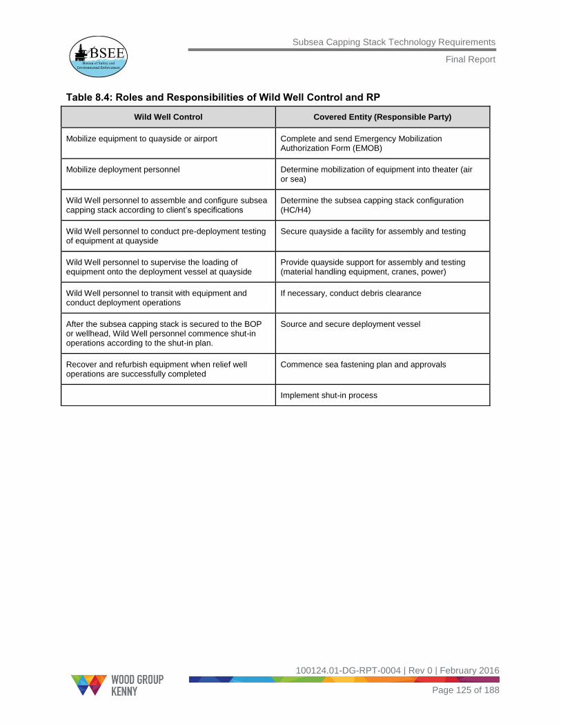
Subsea Capping Stack Technology Requirements
Final Report
100124.01-DG-RPT-0004 | Rev 0 | February 2016
Page 125 of 188
Table 8.4: Roles and Responsibilities of Wild Well Control and RP
Wild Well Control Covered Entity (Responsible Party)
Mobilize equipment to quayside or airport Complete and send Emergency Mobilization Authorization Form (EMOB)
Mobilize deployment personnel Determine mobilization of equipment into theater (air or sea)
Wild Well personnel to assemble and configure subsea capping stack according to client’s specifications
Determine the subsea capping stack configuration (HC/H4)
Wild Well personnel to conduct pre-deployment testing of equipment at quayside
Secure quayside a facility for assembly and testing
Wild Well personnel to supervise the loading of equipment onto the deployment vessel at quayside
Provide quayside support for assembly and testing (material handling equipment, cranes, power)
Wild Well personnel to transit with equipment and conduct deployment operations
If necessary, conduct debris clearance
After the subsea capping stack is secured to the BOP or wellhead, Wild Well personnel commence shut-in operations according to the shut-in plan.
Source and secure deployment vessel
Recover and refurbish equipment when relief well operations are successfully completed
Commence sea fastening plan and approvals
Implement shut-in process

Subsea Capping Stack Technology Requirements
Final Report
100124.01-DG-RPT-0004 | Rev 0 | February 2016
Page 126 of 188
9.0 Industry Survey Response
9.1 Introduction
WGK conducted industry surveys to assess the government and industry regulations,
standards, and guidelines specific to the design, use, and deployment of subsea capping
stacks. Three sets of survey questionnaires were developed with questions that were
specifically related to subsea capping stack Manufacturers, Owners, and Operators. This
section summarizes the responses received as part of the industry survey.
9.2 Subsea Capping Stack Manufacturer – Survey Response
9.2.1 Standards and Guidelines
The specifications, standards, and recommended practices that are applicable for the
design, manufacture, and use of subsea capping stacks are listed in Table 9.1.

Subsea Capping Stack Technology Requirements
Final Report
100124.01-DG-RPT-0004 | Rev 0 | February 2016
Page 127 of 188
Table 9.1: Specifications, Standards, and Guidelines Used in the Design, Manufacture, and Use of Subsea Capping Stacks
Standard Title
API 6A/ISO 10423 Specification for Wellhead and Christmas Tree Equipment
API 6D Specification for Pipeline Valves
API 16A/ISO 13533 Specification for Drill-through Equipment
API 16D Specification for Control Systems for Drilling Well Control Equipment and Control
Systems for Diverter Equipment
API 17A/ISO 13628-1 Recommended Practice for Design and Operation of Subsea Production Systems
API 17D/ISO 13628-4 Specification for Subsea Wellhead and Christmas Tree Equipment
API 17TR8 High-pressure and High-temperature Design Guidelines
API 17W Recommended Practice for Subsea Capping Stacks
API 14D/ISO 10423 Specification for Wellhead Surface Safety Valves and Underwater Safety Valves for
Offshore Service
API RP 2A - WSD Recommended Practice for Planning, Designing, and Constructing Fixed Offshore
Platforms – Working Stress Design
API 53 Blowout Prevention Equipment Systems for Drilling Wells
DNV RP B401 (2005) Cathodic Protection Design
NACE MR0175/
ISO 15156
Petroleum and Natural Gas Industries Materials for Use in H2S Containing Environments
in Oil and Gas Production
API RP 17H Design and Operation of Subsea Production Systems – ROV Interfaces on Subsea
Production Systems
ISO 13628-5 Design and Operation of Subsea Production Systems – Part 5: Subsea Umbilicals
DNV Cert No. 2.7-1 Offshore Containers (DNV certification note on lifting)
DNV Cert No. 2.7-3 Portable Offshore Units (DNV certification note on lifting)
SAE AS 4059 Contamination Classification for Hydraulic Fluids

Subsea Capping Stack Technology Requirements
Final Report
100124.01-DG-RPT-0004 | Rev 0 | February 2016
Page 128 of 188
9.2.2 Regional Requirements
The design requirements for a subsea capping stack depend on the region or regions in
which the subsea capping stack will operate. For example, the GOM has the broadest
range of requirements, such as:
Flow ranges from 50,000 bpd to 300,000 bpd.
Pressure ranges from 10,000 psi to 20,000 psi.
Temperature ranges from -40°F to 350°F.
Addition of electrohydraulic (EH)/Multiplex (MUX) system for topside control.
Subsea capping stack footprints that are smaller on TLP and spar wells.
The requirements for the North Sea are mid-range, compared to the GOM. The Arctic
region requires pre-installed drill-through provisions and a locally available subsea
capping stack. Low temperatures (-40°F) are unique to the Arctic, so fabrication
materials for the subsea capping stack need to be selected accordingly.
9.2.3 Standardization Needs
The companies that participated in the surveys did not recommend standardization of
subsea capping stacks. Similar to BOPs, subsea capping stacks vary significantly in
design, size, and capabilities. Like other oilfield tools, allowing for flexibility in designs
contributes to the best in design features, design practices, and fabrication methods. The
ability to have more than one ‘tool’ to perform the same function creates redundancy and
provides secondary options when needed.
One of the subsea capping stack Manufacturers made the following suggestions:
API flanges and bolted structural connections should be used for the assembly of
components within the subsea capping stack.
The connections used to assemble subsea capping stacks within a containment
system should be standardized. This will allow different subsea capping stacks to be
substituted into the same surrounding containment equipment.
Existing design, readily available drilling, and production components should be
used when possible.
Overall, there could be a degree of standardization, but considerations must be
application-specific. The primary considerations are quick mobilization, straightforward
installation, and simple operation.

Subsea Capping Stack Technology Requirements
Final Report
100124.01-DG-RPT-0004 | Rev 0 | February 2016
Page 129 of 188
9.2.4 Fabrication Time
The average time from receipt of the order to the delivery of a new subsea capping stack
is approximately 9 to 12 months, but it can take up to two years. The delivery time
varies, depending on the complexity of the subsea capping stack design and the
availability of parts.
9.2.5 Maintenance and Testing
While delivering the newly assembled subsea capping stack to the Owner, the
Manufacturer provides the operation and maintenance manuals with procedures for the
subsea capping stack. The subsea capping stack Owner is responsible for storage,
maintenance, testing, and inspection of the equipment. For most of the currently
available subsea capping stacks, maintenance is performed by either the stack
Manufacturer or a third party under the supervision of the subsea capping stack Owner.
For example, OSRL subsea capping stacks are constructed by Trendsetter Engineering,
and Trendsetter is contracted to test and inspect these subsea capping stacks.
9.2.6 Improving Logistics
Suggestions for improving logistics and new technology development include:
Use gate valves instead of rams, which reduces the weight and size of the subsea
capping stack and eliminates the need for Subsea Accumulator Module (SAM) units.
The gate valves can be used only for smaller main bore sizes, as large bore gate
valves are currently not available in the industry.
Expand the use of acoustic controls.
9.3 Subsea Capping Stack Owner – Survey Response
The role of a well containment consortium is to support its member companies by
providing expertise, resources, and equipment during a well control incident. Each
consortium has different methods and procedures in place for the mobilization and
installation of the subsea capping stack equipment:
MWCC owns the equipment and resources required to mobilize and use the subsea
capping stack. MWCC provides the response team and expertise needed to
prepare, mobilize, install, and operate a subsea capping stack in a well
control scenario.
HWCG LLC facilitates mobilization of its contractually dedicated equipment. HWCG
LLC also initiates Mutual Aid protocols as an integral part of its response to a deep
water blowout. HWCG LLC personnel offer response advice to the member

Subsea Capping Stack Technology Requirements
Final Report
100124.01-DG-RPT-0004 | Rev 0 | February 2016
Page 130 of 188
company according to the HWCG Well Containment Plan and the Incident
Management Handbook. The Well Containment Plan contains information related to
a blowout situation, the subsea capping stack, and supporting equipment (debris
removal and dispersant) appropriate for the particular well. The HWCG Incident
Management Handbook provides guidance on managing the team within the
accepted incident command system.
OSRL owns the equipment and has personnel to mobilize the equipment to the
departure port or airport. It is then the responsibility of the member company to
mobilize the equipment to the incident site, use it, and return it to OSRL.
WellCONTAINED owns the equipment and has the personnel required to mobilize
and operate a subsea capping stack in a blowout scenario.
All consortiums are responsible for storing, maintaining, and testing their subsea capping
stack equipment. They contract third parties to perform the periodic maintenance and
testing under the consortiums’ supervision.
Although the currently available subsea capping stacks were designed before
API RP 17W [3], the consortiums that serve the GOM participated in the development of
API RP 17W, and they follow those recommendations. Construction of new subsea
capping stacks will take API RP 17W into consideration.
9.4 Operator – Survey Response
Operators must submit an APD to BSEE before starting drilling operations. The APD
includes documentation that the Operator has access to the equipment required to
respond to a well containment incident on a particular well. BSEE must approve the APD
before the Operator starts drilling.
There are challenges associated with mobilization and deployment of subsea capping
stacks. Finding the right vessel and having a proper sea fastening is critical. Weather
conditions may also present a challenge for deployment of the subsea capping stack
because of its size and weight.
The lessons learned from previous deployments include:
The crane on the transport vessel should be suitable for deploying the subsea
capping stack.
Sea fastening of the subsea capping stack on the vessel must be done carefully.
A vessel with a moon pool is recommended for deployment in higher sea states.
Substantial planning and resources are required in addition to the document control
systems and logistics.

Subsea Capping Stack Technology Requirements
Final Report
100124.01-DG-RPT-0004 | Rev 0 | February 2016
Page 131 of 188
The crew involved in the subsea capping stack mobilization and deployment must
be well trained to respond to a well control incident.
Because the equipment can have limitations, possible upgrades must
be considered.
The Operator must obtain approval for the use of dispersants.

Subsea Capping Stack Technology Requirements
Final Report
100124.01-DG-RPT-0004 | Rev 0 | February 2016
Page 132 of 188
10.0 Subsea Capping Stack Maintenance and Testing Procedures
10.1 Introduction
Regular, comprehensive maintenance and testing of the subsea capping stack
equipment, including response personnel training, is important to ensure that the well
containment equipment remains operable. The subsea capping stack Owner maintains
the subsea capping stack in a readily deployable state by performing periodic
inspections and following the preservation plans provided by the subsea capping stack
Manufacturer. This section provides a detailed review of the different tests, maintenance
procedures, and inspection and preservation plans.
10.2 Maintenance and Testing
Periodic maintenance and testing are critical for the long-term preservation of subsea
capping stacks. All tests and maintenance functions are performed at the storage facility.
A series of testing programs are in place to verify:
That all functions are operationally ready for deployment, including all possible
control systems.
The pressure integrity of the subsea capping stack equipment.
The subsea capping stack Owner must complete the test programs, including visual
inspections, lifting gear recertification, function tests, pressure tests, maintenance
practices, fluid testing for cleanliness and degradation, and operational mobilization
drills.
The subsea capping stack Owner must maintain a testing document that includes the
testing requirements, testing frequency, and testing acceptance criteria.
10.2.1 Testing Types and Test Criteria
The different types of tests performed include function testing, pressure testing, drift
testing, ram testing, valve testing, and choke tests.
Function Testing: A function test on a piece of equipment or a system verifies that the
intended operation is within the design parameters. Function tests must comply with the
requirements of API Standard 53.
Function tests verify:
The fit, form, and function of subsea capping stacks.
Correct installation, handling, and operating procedures.

Subsea Capping Stack Technology Requirements
Final Report
100124.01-DG-RPT-0004 | Rev 0 | February 2016
Page 133 of 188
Function tests are performed on all the major components of the subsea capping stack
(for example, vector connectors, flowline connector, accumulator, wellhead connector,
secondary containment cap, blind rams, and valves).
Pressure Testing: A pressure test on a piece of equipment or system verifies the
functionality of the pressure-retaining connectors and checks for any leaks. The
acceptance criteria of pressure tests must conform to API Specification 17D and
API Standard 53.
Pressure tests conducted on a subsea capping stack during a subsea capping event
must be conducted at the Rated Working Pressure (RWP) of the stack or to the incident
well’s calculated shut-in mudline pressure, whichever is lower.
Pressure test frequency depends on two scenarios:
1. During preservation, as necessary, to ensure that the subsea capping stack is fit for
service and available for callout for a minimum of every 12 months. Typically,
pressure testing is performed every six months. The criteria may differ for each
component of the subsea capping stack.
2. After the disconnection or repair of any pressure-containing or pressure-controlling
element in the subsea capping stack, limited to the affected component
Hydraulic chamber pressure tests are also performed according to the subsea capping
stack Manufacturer’s RWP and in conformance with API Standard 53.
A hydraulic chamber pressure test is the monitored and recorded application of pressure
to any hydraulic operating chamber and associated control system elements, such as:
Subsea capping stack ram cylinders and bonnet assemblies.
Hydraulic valve actuators.
Hydraulic connectors.
Drift Testing: Drift testing of subsea capping stacks, which verifies that the bore is clear
of obstructions, is performed by passing a drift mandrel through the bore of the
assembly. A drift test is required on rams, valves, hydraulic connectors, drilling spools,
and adapters. Drift testing, which is documented as part of the subsea capping stack
acceptance criteria, follows remanufacturing operations that affect the vertical bores.
Drift tests must be performed in accordance with API Specification 6A or API 16A.

Subsea Capping Stack Technology Requirements
Final Report
100124.01-DG-RPT-0004 | Rev 0 | February 2016
Page 134 of 188
Ram Testing: If rams are used in a subsea capping stack, the rams must undergo
pressure and function testing in conformance with API 16A.
Pressures vary, depending on the type of test. For low pressure tests, the pressure is in
the range of 200 to 300 psi; for high pressure tests, it can be up to 15,000 psi.
Typically, ram tests are performed, visually verified, and documented:
Every six months, at a minimum.
When equipment is repaired or remanufactured.
In accordance with the subsea capping stack Owner’s maintenance program.
Valve Testing: If valves are used in a subsea capping stack, the valves must undergo
pressure and function testing in conformance with API Specification 6A. This testing also
includes the verification of any position indicator, and it determines the sealing
capabilities of the assembly.
Typically, valve tests are performed, visually verified, and documented:
Every six months, at a minimum.
When equipment is repaired or remanufactured.
In accordance with the subsea capping stack Owner’s maintenance program.
Choke Tests: The choke body pressure test and the choke function test occur in
one-year increments at a minimum and after any repair or maintenance of the choke.
Choke tests involve function testing and pressure testing of the choke body,
connections, and seals.
10.2.2 Maintenance
Maintenance tasks include inspection and testing of various subsea capping stack
components. The planned maintenance schedules followed for each component of the
subsea capping stack include:
Prevention of elastomer degradation and overall corrosion.
Assurance that the subsea capping stack is ready for mobilization when required
and without additional maintenance or repair.
Performance trending that is critical to uncovering any changes in the operability of
the equipment.
In conformance with API RP 17W, the following items must be inspected periodically to
maintain the subsea capping stack:
Non-metallic goods
API end connections

Subsea Capping Stack Technology Requirements
Final Report
100124.01-DG-RPT-0004 | Rev 0 | February 2016
Page 135 of 188
Critical sealing areas
Ring gaskets
Closure bolting
Cleaning and coating
Repair and remanufacture of the subsea capping stack
Table 10.1 provides the OSRL subsea capping stack maintenance schedule.
10.3 Subsea Capping Stack Inspection
An inspection plan ensures the long-term preservation and readiness of the subsea
capping stack. The frequency of inspection depends on the equipment preservation
conditions and may change, based on the trends and experiences of the service and
maintenance programs. The subsea capping stack Owner is responsible for the periodic
testing and inspection of subsea capping stacks. In most cases, the subsea capping
stack Manufacturer performs the inspection under the supervision of the subsea capping
stack Owner.
The subsea capping stack undergoes a pre-shipping inspection program at the
manufacturing facility. The inspection ensures that the subsea capping stack is ready for
shipping and handling, and that the fluids are drained, if necessary.
10.3.1 At the Preservation Facility
Upon receipt of the subsea capping stack at the long-term preservation location, the
subsea capping stack Owner examines the subsea capping stack and documents a
receiving inspection program.
At a minimum, the receiving inspection includes the following activities:
Inspection for transportation and handling damages
Inspection for completeness and condition of delivery
Inspection and confirmation that the delivery adheres to the scope of supply
Verification that each individual subsea capping stack component is marked with a
serial number, or unique identifier, according to the quality plan
10.3.2 At Quayside
Following shipment from the preservation location, the subsea capping stack should
undergo a predetermined receiving inspection program at quayside to verify its
readiness for deployment.

Subsea Capping Stack Technology Requirements
Final Report
100124.01-DG-RPT-0004 | Rev 0 | February 2016
Page 136 of 188
The inspection will be conducted in accordance with pre-developed, receiving inspection
procedures and will include:
Inspection for transportation and handling damages.
Inspection for completeness of delivery (for example, hydraulic power unit, operating
fluids, running tools, tools and spare parts, handling slings, shackles).
10.4 Subsea Capping Stack Preservation
Long-term preservation of the subsea capping stack ensures that the equipment is
always ready for deployment. The subsea capping stack Manufacturer must generate a
long-term preservation plan with input from the subsea capping stack Owner.
10.4.1 Location
At a minimum, the preservation location must include the following criteria:
Security and protection of all subsea capping stack components
Adequate facility height to allow the use of a crane for equipment handling
Maintenance requirements
Function and pressure testing requirements
Long-term preservation requirements
Transportation requirements to base/quayside/airport
10.4.2 Storage
Storage for the subsea capping stacks must be indoors. If outside preservation is the
only option, the facility and location should avoid flooding, ultraviolet (UV) radiation, dust,
rain, and ice. Only inside preservation provides a measure of protection against extreme
heat, cold, and unexpected weather events. Tarps can be used indoors as an effective
measure against dust, but tarps used outdoors may trap moisture and lead to corrosion.
During storage, the physical properties of most rubber and elastomeric materials change
with age and ultimately become unserviceable. Examples include excessive hardening,
softening, cracking, or other surface degradation. The amount of degradation varies with
time, environmental conditions, and mechanical stress. Expired rubber goods or
elastomeric components (such as the Manufacturer’s recommended expiration date)
must be discarded and prohibited from use in subsea capping stacks. According to
Original Equipment Manufacturer (OEM) recommendations, elastomeric materials
should be stored in ambient temperature conditions.

Subsea Capping Stack Technology Requirements
Final Report
100124.01-DG-RPT-0004 | Rev 0 | February 2016
Page 137 of 188
10.4.3 Preservation Fluids
Water-based hydraulic preservation fluids specifically designed for long-term
preservation must be used. The preservation fluids must be inspected periodically. If the
fluids are found to be ineffective, they must be replaced.
10.4.4 Spare Parts
Spare parts are sensitive to temperature or humidity and must be preserved to avoid a
limited shelf life.
10.4.5 OSRL 15K Subsea Capping Stack Preservation, Maintenance, and Testing Procedures
Table 10.1 provides the maintenance schedule of an OSRL 15K subsea capping stack.
Table 10.1: OSRL 15K Subsea Capping Stack Maintenance Schedule
Step Monthly Quarterly Semi-
Annually Annually
1 – Visual Inspection for Corrosion and Damage
Conduct visual inspection for corrosion and
damage
Y Y Y Y
2 – Bottom H4 Connector Function and Pressure Test, Drift Test, and OEM
Recommended
Conduct drift test Y Y
Lubricate bottom H4 connector Y
Function test bottom H4 connector Y Y Y
Pressure test bottom H4 connector Y Y
3 – Vector Connectors #1-4 Function Test
Conduct vector connectors function test Y Y Y
4 – Vector Connectors #1-4 Back Seal Test
Conduct vector connectors back seal test Y Y Y

Subsea Capping Stack Technology Requirements
Final Report
100124.01-DG-RPT-0004 | Rev 0 | February 2016
Page 138 of 188
Step Monthly Quarterly Semi-
Annually Annually
5 – Bottom H4 Connector Test for Seal Retain/Release
Conduct bottom H4 connector test for seal
retain/release
Y Y Y
6 – Secondary Containment Cap Function Test
Conduct secondary containment cap function
test
Y Y Y
7 – Secondary Containment Cap Test for Seal Retain/Release
Conduct secondary containment cap test for
seal retain/release
Y Y Y
8 – Fill Bore with Fluid
Fill the bore with fluid Y Y
9 – Secondary Barrier Test Procedure
Conduct secondary barrier test procedure Y Y
10 – Intermediate Barrier Pressure and Function Test
Conduct intermediate barrier pressure and
function test
Y Y
11 – Primary Barrier Function and Pressure Test
Verify/remove hot stabs for secondary
connector ROV
Y Y
Conduct primary barrier function test Y Y
Close 5-inch gate valves Y Y
Vent via hose connected to hot stabs from
secondary
Y Y
Close ram Y Y Y

Subsea Capping Stack Technology Requirements
Final Report
100124.01-DG-RPT-0004 | Rev 0 | February 2016
Page 139 of 188
Step Monthly Quarterly Semi-
Annually Annually
Close 5-inch gate valves, and open bleed
valves
Y Y
Conduct primary barrier pressure test Y Y
Open ram Y Y Y
Close vent valves Y Y
12- 5-inch Gate Valves Function Test
Conduct 5-inch gate valves function test Y Y Y
13 – 5-inch Choke Valve Function Test
Conduct 5-inch choke valve function test Y Y Y
14 – Running Tool
Pick up and inspect running tool Y Y Y
15 – Annual Rigging Certification
Conduct annual rigging certification Y
16 – Inspect Ram Cavities and Seals
Inspect ram cavities and seals Y
Detailed Procedures of Each Test
Bottom H4 Connector Function, Pressure, and Drift Test
1. Drain the bore of fluid.
2. Rig up the connector for the drift test; lower the drift into the bore, and pick up the
drift from the bore.
3. Open and remove vector connectors #1 and #4.
4. Pull a fluid sample for testing.
5. Unlatch the bottom H4 connector.
6. Move the subsea capping stack into the inspection stand.
7. Check the tubing and fittings for leaks.

Subsea Capping Stack Technology Requirements
Final Report
100124.01-DG-RPT-0004 | Rev 0 | February 2016
Page 140 of 188
8. Lubricate the bottom of the H4 connector.
9. Move the subsea capping stack onto the test stand.
10. Latch the Bottom H4 Connector (4x).
Vector Connectors Function Test
1. Open the vector connector (#1).
2. Close the vector connector (#1).
3. Repeat for vector connectors (#2-4).
Vector Connectors Back Seal Test
1. Increase the pressure to 1,500 psi on the vector connector (#1).
2. Monitor and chart pressure for 10 minutes.
3. Repeat for vector connectors (#2-4).
Bottom H4 Connector Test for Seal Retain/Release
1. Seal and retain the bottom H4 connector.
2. Check the tubing and fittings for leaks.
3. Seal and release the bottom H4 connector.
Secondary Containment Cap Function Test
1. Unlatch the secondary containment cap,
2. Check the tubing and fittings for leaks.
3. Latch the secondary containment cap.
Secondary Containment Cap Test for Seal Retain/Release
1. Seal and retain the secondary containment cap.
2. Check the tubing and fittings for leaks.
3. Seal and release the secondary containment cap.
Secondary Barrier Test
1. Blank off the elbows and chokes.
2. Open the 5-in. gate valves.
3. Verify that the dummy hot stabs are installed.
4. Open the ½-in. isolation valves.
5. Increase the pressure to 15,000 psi and record the pressure readings.

Subsea Capping Stack Technology Requirements
Final Report
100124.01-DG-RPT-0004 | Rev 0 | February 2016
Page 141 of 188
Intermediate Barrier Pressure and Function Test
1. Close the ½-in. isolation valves.
2. Remove the dummy hot stabs.
3. Apply pressure to 200 – 300 psi and record the pressure readings.
4. Apply pressure to 15,000 psi and record the pressure readings.
Primary Barrier Pressure and Function Test
1. Remove the dummy hot stabs.
2. Open the ½-in. isolation valves and install the hot stabs on the secondary
containment cap.
3. Apply 1,500 psi pressure to the system.
4. Close the blind ram.
5. Check the tubings and fittings for leaks.
6. Close the 5-in. gate valves.
7. Open the bleed valves.
8. Apply pressure to 200 – 300 psi and record the pressure readings.
9. Apply pressure to 15,000 psi and record the pressure readings.
10. Open the blind ram.
11. Check the tubing and fittings for leaks.
12. Close the ½-in.isolation valves.
13. Close the vent valves on the block elbows.
5-in. Gate Valves Function Test
Open gate valves (#1 – 4)
5-in. Choke Valves Function Test
1. Close the choke valve (#1).
2. Open the choke valve (#1).
3. Repeat for choke valves (#2 and 3).
Running Tool Function Test
1. Latch the running tool.
2. Check the tubing and fittings for leaks.
3. Unlatch the running tool.

Subsea Capping Stack Technology Requirements
Final Report
100124.01-DG-RPT-0004 | Rev 0 | February 2016
Page 142 of 188
11.0 Subsea Capping Stack Deployment Demonstrations
11.1 Introduction
Subsea capping stack consortiums that serve the GOM have demonstrated their well
containment capabilities in simulated well control scenarios. The information related to
the demonstration exercises is provided in this section.
11.2 MWCC Subsea Capping Stack Deployment Demonstration
In July 2012, at the request of BSEE, the MWCC partnered with member company Shell
Oil to perform a demonstration of MWCC well containment capabilities. The goal of the
demonstration was to prove to federal regulators that MWCC:
Is ready to respond to well control incidents.
Has the appropriate procedures in place.
Provides equipment that can safely and efficiently respond deep water well
control incidents.
11.2.1 Test Description
MWCC assembled its response team in the Emergency Response Center, where details
of the demonstration were provided. The subsea capping stack, which stands roughly 30
ft. tall and weighs approximately 100 tons, was transported from the ASCO facility in
Houston to the Greensport dock. While at Greensport, the secondary containment cap
was installed and pre-deployment tests were performed. Additional ancillary equipment,
including the hydraulic accumulator and four vector connectors, was shipped to Port
Fourchon, where it was loaded onto the vessel for deployment [42]. (Refer to Figure 11.1
for a map of the simulated wellhead region.)
At the Greenport dock, a crane with a 500-ton lift capacity was used to lift and move the
subsea capping stack to the Houston ship channel, where it was lowered onto the Laney
Chouest22. The subsea capping stack then underwent a simulated deployment using the
vessel’s A-frame to lower the subsea capping stack just above the water line. The
subsea capping stack was then sea-fastened onto a shipping stand and transported 304
miles offshore to simulated deep water well in the GOM.
When the capping stack arrived offshore, it was lowered approximately 6,900 ft. on a
wire, using a heave compensated landing system (HCLS), from the back of the vessel
22
Laney Chouest is an offshore supply vessel owned by Edison Chouest Offshore.

Subsea Capping Stack Technology Requirements
Final Report
100124.01-DG-RPT-0004 | Rev 0 | February 2016
Page 143 of 188
onto the simulated wellhead. The subsea capping stack landed and latched onto the
simulated wellhead, where all necessary functions were completed. Pressure tests were
performed to confirm the equipment’s ability to safely and effectively cap a well. The
mobilization, function, and pressure testing performed as expected and within the
anticipated timeline. The subsea capping stack and ancillary equipment were then
transported back to shore, where they are stored and maintained in a ready state.
Figure 11.1: Map Showing Simulated Wellhead Region
During the course of this exercise, BSEE inspectors and engineers monitored the
demonstration from MWCC headquarters. Additionally, the BSEE director met with
MWCC and Shell throughout the demonstration to witness the various phases of system
deployment and participated in daily Unified Command (UC) briefings with the U.S. DOI.
BSEE inspectors were staged at each work location to monitor and endorse the planned
activities.
MWCC successfully demonstrated the ability to cap a well in the following ways:
Deployment was executed with no recordable incidents and within the
anticipated timeline.
The arrival of the response equipment was completed on the first day of operations.
The subsea capping stack was mobilized and pre-deployment testing
was completed.
The subsea capping stack was deployed using HCLS.
Subsea capping stack function and pressure testing were demonstrated.

Subsea Capping Stack Technology Requirements
Final Report
100124.01-DG-RPT-0004 | Rev 0 | February 2016
Page 144 of 188
The well containment screening tool and flow modeling established pressure
response ranges for a simulated well.
Video and pressure data were available for monitoring and decision making.
The source control branch managed the overall response operations.
11.2.2 Test Results
Through this demonstration, the MWCC confirmed its ability to safely and effectively
respond to a well control incident in the deep water GOM by successfully fulfilling the
BSEE’s requirements for the specified scenario. The success of the demonstration
resulted from a strong collaboration between government and industry, particularly
MWCC members.
11.3 HWCG Subsea Capping Stack Deployment Demonstration
The BSEE; Noble Energy, Inc.; and HWCG LLC have successfully completed the
full-scale deployment of critical well control equipment to assess Noble Energy’s ability
to respond to a potential subsea incident in the deep water GOM [38].
The unannounced deployment drill, which was undertaken at the direction of BSEE on
April 30, 2013, tested the HWCG subsea capping stack system—a 20-ft. tall,
146,000-pound piece of equipment similar to the one that stopped the flow of oil from the
Macondo well following the Macondo oil spill in 2010. During this exercise, the subsea
capping stack was deployed in more than 5,000 ft. of water in the GOM. When it reached
the site, the system was lowered to a simulated wellhead (a pre-set parking pile) on the
ocean floor, connected to the wellhead, and pressurized to 8,400 psi.
The BSEE, the U.S. Coast Guard, the Louisiana Offshore Coordinator’s Office, and
Noble Energy combined unique perspectives in a Unified Command structure to achieve
a shared goal. Through coordination within the Incident Command System structure, all
objectives were met [39].
BSEE engineers, inspectors, and oil spill response specialists have evaluated the
deployment operations and identified lessons learned as the bureau continues its efforts
to improve safety and environmental protection across the offshore oil and natural
gas industry.
HWCG LLC’s ability to quickly and effectively respond to a call from Noble Energy or any
other Operator in the consortium has been made possible by a combination of the
Mutual Aid agreement and the contracts in place for equipment that is staffed and
working in the GOM each day.

Subsea Capping Stack Technology Requirements
Final Report
100124.01-DG-RPT-0004 | Rev 0 | February 2016
Page 145 of 188
12.0 Recommended Regulations for Subsea Capping Stacks
12.1 Introduction
WGK has developed the subsea capping stack recommended regulations with support
and feedback from the well containment consortiums and the subsea capping stack
manufacturing companies. This section provides the draft subsea capping stack
regulations and recommends to BSEE how and where these regulations should be
incorporated into 30 CFR 250 [33].
12.2 Recommended Location for Subsea Capping Stack Regulations in 30 CFR 250
WGK based the subsea capping stack recommended regulations on the current
regulations and used the same numbering and format. WGK recommends that the
sections in Table 12.1 be incorporated into 30 CFR 250 [33]. Table 12.1 also provides
the subsea capping stack section titles to be included and the justification for each.
WGK considered BSEE’s Proposed Rule(s) when developing the subsea capping stack
recommended regulations but did not follow the numbering in the Proposed Rule(s).
Table 12.1: Recommended Sections to Be Incorporated in 30 CFR 250
30 CFR 250 Location Recommended Section Justification
Subpart A – General
Authority and Definition of
Terms
§250.105 Definitions
Subsea capping stack
definition
Subsea capping stack system definition
is recommended to be included as part
of definitions
Subpart A – General
References
§250.198 Documents
incorporated by reference,
Paragraph (h)
API 17H incorporated as
reference
API 17H is referenced in the subsea
capping stack regulations and should be
included in this section.
Subpart D – Oil and Gas
Drilling Operations
Applying for a Permit to Drill
Subsea capping stack
information to be included in
the APD
Provides subsea capping stack system
documentation as required by BSEE to
issue a Permit to Drill.
Subpart D – Oil and Gas
Drilling Operations
Subsea Capping Stack System
Requirements
This section will have new regulations
for subsea capping stacks.

Subsea Capping Stack Technology Requirements
Final Report
100124.01-DG-RPT-0004 | Rev 0 | February 2016
Page 146 of 188
Subpart A, §250.105 provides definitions for the terms used in 30 CFR 250 and will be
useful to incorporate its subsea capping stack definition.
Subpart A, §250.198 lists the documents incorporated by reference in 30 CFR 250. The
documents, which are organized based on the publishing organization, are:
Paragraph (e) – provides reference documents published by the American Concrete
Institute (ACI)
Paragraph (f) – provides reference documents published by the American Institute
of Steel Construction, Inc. (AISC)
Paragraph (g) – provides reference documents published by the American National
Standards Institute (ANSI)
Paragraph (h) – provides reference documents published by the American
Petroleum Institute (API).
WGK recommends that API 17H be included under paragraph (h).
Subpart D, §250.410 thru §250.419 provides the detailed procedures, requirements, and
documentation for BSEE to approve an APD. Because this section currently does not
have information related to subsea capping stacks, WGK recommends that this
information be included, as shown in Table 12.2. Currently, Operators are submitting
subsea capping stack documentation to BSEE in accordance with NTL 2010-N10.
Table 12.2: Recommended Location for Subsea Capping Stack APD Information
Subpart D - Oil and Gas Drilling Operations
Applying for a Permit to Drill
Current
Regulation
§250.410 How do I obtain approval to drill a well?
§250.411 What information must I submit with my application?
§250.412 What requirements must the location plat meet?
§250.413 What must my description of well drilling design criteria address?
§250.414 What must my drilling prognosis include?
§250.415 What must my casing and cementing programs include?
§250.416 What must I include in the diverter and BOP descriptions?
§250.417 What must I provide if I plan to use a mobile offshore drilling unit
(MODU)?
§250.418 What additional information must I submit with my APD?
Recommended
Regulation §250.419
What must I include in the subsea capping stack system
descriptions?

Subsea Capping Stack Technology Requirements
Final Report
100124.01-DG-RPT-0004 | Rev 0 | February 2016
Page 147 of 188
Subpart D has different sections, such as Diverter System Requirements and BOP
System Requirements, and WGK therefore recommends that there be a separate
section for subsea capping stack System Requirements. Table 12.3 provides the
recommended location and the CFR numbering for this proposed section.
Table 12.3: Recommended Location – Subsea Capping Stack System Requirements
Subpart D – Oil and Gas Drilling Operations
Section Title CFR Number
Current
Regulations
General Requirements §250.400 thru §250.409
Applying for a Permit to Drill §250.410 thru §250.418
Casing and Cementing Requirements §250.420 thru §250.428
Diverter System Requirements §250.430 thru §250.434
Blowout Preventer (BOP) System Requirements §250.440 thru §250.451
Drilling Fluid Requirements §250.455 thru §250.459
Other Drilling Requirements §250.460 thru §250.463
Applying for a Permit to Modify and Well Records §250.465 thru §250.469
Recommended
Regulation Subsea Capping Stack System Requirements §250.480 thru §250.485
Current
Regulation Hydrogen Sulfide §250.490

Subsea Capping Stack Technology Requirements
Final Report
100124.01-DG-RPT-0004 | Rev 0 | February 2016
Page 148 of 188
12.3 Recommended Subsea Capping Stack Regulations
WGK has drafted the recommended subsea capping stack regulatory guidelines in a
format which is similar to the BOP regulations that are currently available. Because the
subsea capping stack design and usage differ from the BOPs, their regulations have
been developed separately. These regulations provide the minimum requirements for
subsea capping stacks in terms of their design, maintenance, and testing procedures to
verify that the subsea capping stack is ready for use during an emergency scenario.
The recommended regulations provide the minimum requirements for subsea capping
stacks. These regulations have been developed with the goal to be as generic as
possible and allow for future development and innovation.
The recommended subsea capping stack CFR is divided into three sections:
1. Definition and References
2. Documentation to be submitted as part of the APD
3. Subsea Capping Stack System Requirements
Table 12.4, Table 12.5, and Table 12.6 provide the three sections of the recommended
CFRs for subsea capping stacks.
Table 12.4: Subsea Capping Stack CFR – Definition and References
Subpart A – General
§250.105 Definitions
Subsea capping stack system means any mechanical device that may be installed onto a subsea well with
the primary purpose of shutting in a flowing well through mechanical isolation after a blowout has occurred.
The device may be deployed from the surface and attached to a well subsequent to a blowout event and
may serve as a mechanical connection point to facilitate:
(1) The controlled flow of fluids originating within the well to a surface containment system for
collection and disposal; and
(2) The pumping of kill fluid into the well.
§250.198 Documents incorporated by reference.
API RP 17H, Remotely Operated Tools and Interfaces on Subsea Production Systems, Second Edition,
June 2013; Errata January 2014; incorporated by reference at §250.480(l).

Subsea Capping Stack Technology Requirements
Final Report
100124.01-DG-RPT-0004 | Rev 0 | February 2016
Page 149 of 188
Table 12.5: Subsea Capping Stack CFR – Documentation Required as Part of APD
Subpart D – Oil and Gas Drilling Operations
Applying for a Permit to Drill
30 CFR 250.419 What must I include in the subsea capping stack system descriptions?
Plan as used in §250.419 is defined as an approved plan or approved permit which contains information
related to subsea capping stack systems, capabilities, and/or well data that is specific to well subsea
capping stack interface.
You must include the following:
(a) Proof of access to a suitable subsea capping stack system;
(b) A Plan for mobilization of the subsea capping stack system to the incident location within a reasonable
time predetermined by the Regional Director;
(c) A description of the subsea capping stack system and system components, including pressure ratings
of subsea capping stack equipment;
(d) A schematic drawing of the subsea capping stack equipment that shows:
(1) The inside diameter(s) of the subsea capping stack;
(2) The number and size of all outlets and inlets;
(3) The number, types, locations, and working pressure ratings of all closure devices;
(4) The outlet bore(s) connection types, sizes, and working pressure ratings;
(5) The lower interface connection type, size, and working pressure rating; and
(6) The pressure monitoring and chemical injection port location(s).
(e) Proof that:
(1) The subsea capping stack is suitable for use based on the Plan;
(2) The subsea capping stack is capable of interfacing with specified wellhead and rig BOP
systems; and
(3) The subsea capping stack will operate in the conditions in which it will be used;
Amend §250.410(a) and §250.411(h) as follows:
§250.410 How do I obtain approval to drill a well?
(a) Submit the information required by §§250.411 through 250.419;
Add an additional row to the table in 30 CFR 250.411 as follows:
§250.411 What information must I submit with my application?
(h) Subsea capping stack system requirements . . . §250.419

Subsea Capping Stack Technology Requirements
Final Report
100124.01-DG-RPT-0004 | Rev 0 | February 2016
Page 150 of 188
Table 12.6: Draft CFR – Subsea Capping Stack System Requirements
Subpart D – Oil and Gas Drilling Operations
Subsea Capping Stack System Requirements
30 CFR 250.480 What are the subsea capping stack system requirements?
Plan as used in §250.480 is defined as an approved plan or approved permit which contains information
related to subsea capping stack systems, capabilities, and/or well data that is specific to well subsea
capping stack interface.
(a) The working pressure rating of each subsea capping stack component exposed to wellbore pressure
must exceed the maximum anticipated wellhead pressure (MAWHP).
(b) The subsea capping stack system must have primary bore closure device(s). The closure device(s)
must be located above the diverter.
(c) The subsea capping stack system must contain one or more outlets for diverting flow from and/or
pumping kill fluid into the primary bore. Diverter outlet(s) must be located below the primary bore
closure device(s).
(d) Each diverter path must have a closure device(s) between the outlet and primary bore.
(e) The diverter outlet(s) may be equipped with:
(1) A subsea connector that is capable of installation or removal by an ROV;
(2) An interface compatible with a designated containment system; and
(3) An interface that is compatible for well kill operations.
(f) The subsea capping stack system must have a means of injecting chemicals below the diverter
outlet(s). The location of the chemical injection may alternately be located below the outermost
mechanical isolation device in the primary bore and each diverter outlet(s). The chemical injection
path(s) must have a closure device located between the chemical injection inlet and the path(s)
intersection with the primary bore.
(g) The subsea capping stack system must be capable of monitoring the primary bore pressure below each
closure device.
(h) The subsea capping stack system must have a connector assembly that is compatible with the
interfaces identified in the Plan. The connector must:
(1) Interface with the incident well;
(2) Accommodate various space-out requirements;
(3) Remain latched if there is a loss of control line pressure; and
(4) Be capable of providing for hydrate mitigation or remediation within the latch assembly.
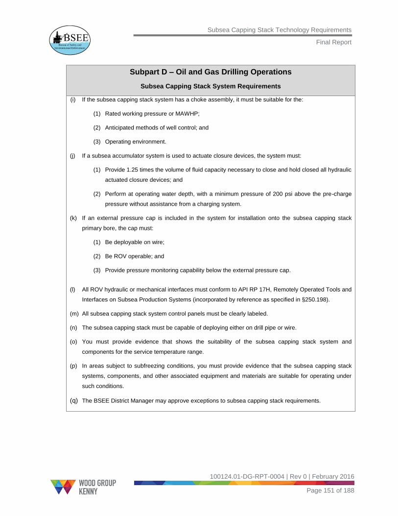
Subsea Capping Stack Technology Requirements
Final Report
100124.01-DG-RPT-0004 | Rev 0 | February 2016
Page 151 of 188
Subpart D – Oil and Gas Drilling Operations
Subsea Capping Stack System Requirements
(i) If the subsea capping stack system has a choke assembly, it must be suitable for the:
(1) Rated working pressure or MAWHP;
(2) Anticipated methods of well control; and
(3) Operating environment.
(j) If a subsea accumulator system is used to actuate closure devices, the system must:
(1) Provide 1.25 times the volume of fluid capacity necessary to close and hold closed all hydraulic
actuated closure devices; and
(2) Perform at operating water depth, with a minimum pressure of 200 psi above the pre-charge
pressure without assistance from a charging system.
(k) If an external pressure cap is included in the system for installation onto the subsea capping stack
primary bore, the cap must:
(1) Be deployable on wire;
(2) Be ROV operable; and
(3) Provide pressure monitoring capability below the external pressure cap.
(l) All ROV hydraulic or mechanical interfaces must conform to API RP 17H, Remotely Operated Tools and
Interfaces on Subsea Production Systems (incorporated by reference as specified in §250.198).
(m) All subsea capping stack system control panels must be clearly labeled.
(n) The subsea capping stack must be capable of deploying either on drill pipe or wire.
(o) You must provide evidence that shows the suitability of the subsea capping stack system and
components for the service temperature range.
(p) In areas subject to subfreezing conditions, you must provide evidence that the subsea capping stack
systems, components, and other associated equipment and materials are suitable for operating under
such conditions.
(q) The BSEE District Manager may approve exceptions to subsea capping stack requirements.

Subsea Capping Stack Technology Requirements
Final Report
100124.01-DG-RPT-0004 | Rev 0 | February 2016
Page 152 of 188
Subpart D – Oil and Gas Drilling Operations
Subsea Capping Stack System Requirements
30 CFR 250.481 What are the subsea capping stack system maintenance, inspection, and preservation requirements?
(a) You must maintain, inspect, and preserve your subsea capping stack system to ensure that the
equipment functions properly and that the system is ready for mobilization at any time with no need for
additional maintenance or repair.
(b) The BSEE District Manager must approve the subsea capping stack maintenance, inspections, and
preservation procedures.
(c) You must ensure that an official representative of BSEE will have access to the location to witness any
maintenance, inspection, or preservation, and verify that this information is submitted to BSEE. Prior to
any subsea capping stack maintenance, inspections, or preservation activities, you must notify the
BSEE District Manager at least 72 hours in advance.
(d) You must document and record the results of your subsea capping stack inspections and maintenance
actions and make the records available to BSEE upon request.
(e) You must maintain your records as specified in §250.484.
30 CFR 250.482 What are the subsea capping stack pressure test requirements?
(a) You must pressure test your subsea capping stack system to ensure that the equipment functions
properly and that the system is ready for mobilization at any time with no need for additional
maintenance or repair. Required pressure test frequencies are as follows:
(1) The subsea capping stack assembly must be pressure tested on a bi-annual basis, but no greater
than 210 days between testing activities;
(2) Subsea capping stack closure device(s) must be individually pressure tested a minimum of once
per year, but no greater than 379 days between testing activities; and
(3) Subsea capping stack component(s) that are affected following the disconnection or repair of any
well-pressure containment seal must be pressure tested after repair is completed.
(b) You must conduct each individual pressure test as a hydrostatic test and hold pressure long enough to
demonstrate that the tested assembly or component(s) can hold the required pressure. Required test
pressures and durations are as follows:
(1) Low pressure test. All low pressure tests must be between 250 and 350 psi. Any initial pressure
above 350 psi must be bled back to a pressure between 250 and 350 psi before starting the test.

Subsea Capping Stack Technology Requirements
Final Report
100124.01-DG-RPT-0004 | Rev 0 | February 2016
Page 153 of 188
Subpart D – Oil and Gas Drilling Operations
Subsea Capping Stack System Requirements
If the initial pressure exceeds 500 psi, you must bleed back to zero and re-initiate the test;
(2) High pressure test. The high pressure test must equal the rated working pressure of the equipment
or be 500 psi greater than your calculated maximum anticipated wellhead pressure (MAWHP); and
(3) Duration of pressure test. Each test must hold the required pressure for 5 minutes. If the equipment
does not hold the required pressure during a test, you must correct the problem and retest the
affected component(s).
(c) You must record test pressures on pressure charts or a digital recorder.
(d) The BSEE District Manager must approve the subsea capping stack system pressure test procedures in
advance of the testing.
(e) You must ensure that an official representative of BSEE will have access to the location to witness any
pressure testing and verify information that is submitted to BSEE. You must notify the BSEE District
Manager at least 72 hours in advance of any subsea capping stack pressure testing.
(f) You must document and record the successful results of your subsea capping stack pressure testing
and make the records available to BSEE upon request.
(g) You must maintain your records as specified in §250.484.
30 CFR 250.483 What additional subsea capping stack system test must I perform?
(a) You must function test all subsea capping stack closure devices on a quarterly basis (not to exceed 104
days) from the last function test;
(b) You must test all subsea capping stack ROV controlled functions (§250.480[l]) on your subsea capping
stack system on an annual basis, to verify interface compatibility between the ROV tool(s) and subsea
capping stack control interface(s);
(c) You must document and record the successful results of your subsea capping stack testing and make
the records available to BSEE upon request; and
(d) You must maintain your records as specified in §250.484.

Subsea Capping Stack Technology Requirements
Final Report
100124.01-DG-RPT-0004 | Rev 0 | February 2016
Page 154 of 188
Subpart D – Oil and Gas Drilling Operations
Subsea Capping Stack System Requirements
30 CFR 250.484 What are the recordkeeping requirements for subsea capping stack
system tests?
You must record the time, date, and results of all maintenance, inspection, preservation, and testing
activities conducted on the subsea capping stack system. In addition, you must:
(a) Identify any problems or irregularities observed during system maintenance, inspection, preservation,
and testing and record the actions taken to remedy the problems or irregularities;
(b) Document the sequential order of subsea capping stack closure device actuation and pressure testing
durations and record the actuation times for closure device(s);
(c) Require your onsite representative to sign and date all reports and successful test charts and reports as
correct; and
(d) Retain all records, including pressure charts or digital records, maintenance reports, inspection reports,
test reports, and referenced documents pertaining to tests, actuations, and inspections at the subsea
capping stack system for a period of 5 years.
30 CFR 250.485 What are the subsea capping stack personnel requirements?
You must:
(a) Ensure that personnel who are authorized to operate subsea capping stack equipment at the surface
are trained on the specific subsea capping stack systems and controls.
(b) Ensure that personnel who are authorized to operate subsea capping stack equipment subsea are
trained on the specific ROV system to be used and have been familiarized with subsea capping stack
applications and controls.
12.4 Discussion – Recommended Subsea Capping Stack CFR
During a well control scenario, a variety of source control and containment equipment
may be required, depending on the condition of the incident well. The equipment may
include debris removal tools, dispersant systems, a subsea capping stack, and a
containment system (flowlines, risers, manifolds, capture vessels, support vessels). This
study is limited to subsea capping stacks and focuses on the design, testing, inspection,
and maintenance requirements of subsea capping stacks.

Subsea Capping Stack Technology Requirements
Final Report
100124.01-DG-RPT-0004 | Rev 0 | February 2016
Page 155 of 188
A definition of the subsea capping stack system is provided in §250.105. Depending on
the conditions of the well (cap only or cap and flow), the subsea capping stack may need
to be connected to a surface containment system and be capable of pumping kill fluid
into the well. The subsea capping stack system includes the auxiliary equipment such as
the subsea accumulators and hot stabs. WGK has added API 17H as a reference
in §250.198.
‘Plan,’ as it is defined in §250.419 and §250.480, can be any document that is approved
by BSEE and includes information related to subsea capping stack systems, their
capabilities, and data that is specific to the well capping interface. Currently, the subsea
capping stack information being submitted to BSEE is a part of documents such as the
Regional Containment Demonstration (RCD)23, Well Containment Screening Tool Plus
(WCST+), and the Well Containment Plan, depending on the Operator.
The RCD, which is updated every two years, serves as a pre-planned strategy for
containment and a protocol for managing an emergency response. The WCST+ is
submitted with the individual APD or Application for Permit to Modify (APM) and includes
the following:
1. Copy of Operator’s RCD approval letter
2. Compliance statement signed by an authorized company official
3. The WCST+, including fluid gradient and broaching analysis (if required)
4. Relief Well Plan
5. Cap and flow information (if required)
6. Rig-specific data, including the subsea capping stack connection information and
subsea capping stack deployment procedures for the manual disconnect of the
LMRP from the BOP or the BOP from the wellhead.
7. Acknowledgement that the Operator’s well containment capabilities have not been
reduced since approval of the RCD and no major changes have been made.
To avoid any confusion, the generic term ‘Plan’ is used in the CFR.
Section 250.419 provides details of the subsea capping stack information that must be
submitted to BSEE along with the APD for obtaining a permit to drill. If the incident well
cannot be completely shut in because of the pressure integrity of the wellbore, additional
documentation showing access to a suitable containment system that is ready to
respond in an emergency scenario will be submitted.
23
The purpose of the RCD is to provide the BSEE with the detailed guidelines, processes, and procedures needed to contain a hydrocarbon release from a GOM deep water well that has been drilled using subsea BOPs or surface BOPs on floating facilities.

Subsea Capping Stack Technology Requirements
Final Report
100124.01-DG-RPT-0004 | Rev 0 | February 2016
Page 156 of 188
Maximum anticipated wellhead pressure (MAWHP) is the highest pressure predicted to
be encountered at the wellhead in a subsea well. Section 250.480 provides the minimum
subsea capping stack system requirements (refer to Table 12.6).
The subsea capping stack system components that are exposed to wellbore pressure
must be rated to a working pressure greater than the MAWHP (§250.480[a]) and the
temperature rating suitable for the service temperature range (§250.480[o]).
The subsea capping stack must have a primary bore, one or more diverter outlets, and a
means to inject chemicals. The primary bore must have a closure device above the
diverter. The diverter paths must have closure devices between the outlet and the
primary bore. Depending on the well conditions, the diverter path may be equipped with
choke valves or an interface that is compatible with the designated containment system.
The subsea connectors must be ROV operable for the installation or removal of
equipment at the diverter outlets.
The lower connector must be compatible with the identified interfaces (wellhead or
BOP). The connector must accommodate space-out requirements and remain latched
under loss of control line pressure. The connector must also have hydrate mitigation
capability within the latch assembly. All ROV and hydraulic interfaces must conform to
API 17H, and the control panels must be clearly labeled.
If a subsea accumulator is used, it must provide at least 1.25 times the volume of fluid
necessary to close all hydraulically actuated closure devices. If an external pressure cap
is used, it must be ROV operable and have pressure monitoring capability below the
external pressure cap.
The subsea capping stack must be deployable by drill pipe or wire. For subfreezing
conditions such as the Arctic, the Operator must show evidence that the subsea capping
stack system is designed to operate under such conditions.
Section 250.481 states that the District Manager must approve subsea capping stack
maintenance, inspection, and preservation procedures. The District Manager must be
notified at least 72 hours in advance and must have access for the official BSEE
representative to witness any maintenance, inspection, or preservation activities. The
results of the inspections and maintenance must be recorded and made available to
BSEE upon request.
Section 250.482 provides the pressure test requirements. The pressure tests must be
conducted bi-annually with no more than 210 days between testing activities. In
accordance with API 17W, the subsea capping stack is tested to a low pressure of 250
psi to 350 psi. The high pressure tests are conducted to the rated working pressure of
the equipment or 500 psi greater than calculated MAWHP. To ensure that the subsea

Subsea Capping Stack Technology Requirements
Final Report
100124.01-DG-RPT-0004 | Rev 0 | February 2016
Page 157 of 188
capping stack can hold pressure, the duration of the pressure test must be a minimum of
5 minutes.
Section 250.483 states that the function testing must be conducted on a quarterly basis,
not to exceed 104 days from the last function test. All ROV-controlled functions must be
tested on an annual basis. The results of the tests must be recorded and made available
to BSEE upon request.
Section 250.484 provides the recordkeeping requirements for all the maintenance,
inspection, preservation, and testing activities conducted on the subsea capping system.
Section 250.485 provides the subsea capping stack personnel requirements at both the
yard and subsea.

Subsea Capping Stack Technology Requirements
Final Report
100124.01-DG-RPT-0004 | Rev 0 | February 2016
Page 158 of 188
13.0 Recommended Potential Incident of Noncompliance and Guideline List for Subsea Capping Stacks
13.1 Introduction
The OCS Lands Act authorizes and requires BSEE to provide an annual scheduled
inspection and a periodic unscheduled (unannounced) inspection of all oil and gas
operations on the OCS. The annual inspection examines all safety equipment that is
designed to prevent blowouts, fires, spills, or other major accidents.
The Potential Incident of Noncompliance (PINC) and Guideline List is the checklist of
items that BSEE inspects to pursue safe operations on the OCS. WGK has developed
the subsea capping stack PINC List based on the recommended subsea capping stack
CFRs in Section 12.0. The well containment consortiums and subsea capping stack
Manufacturers have provided feedback on the PINC List to ensure that it complies with
the current regulations in place (CFRs, NTLs) and covers all the aspects of testing,
maintenance, inspection, and preservation requirements.
This section provides a set of usable PINC and Guidelines that have been prepared in
accordance with the format included in the National PINC Guideline List. Agency
inspectors both in the field and at onshore support bases and manufacturing
establishments can use these PINC. In addition, WGK has made a recommendation
regarding the location of the subsea capping stack PINC List in the National PINC
Guideline List.
13.2 Recommended Location for Subsea Capping Stack PINC Guidelines
The PINC Guideline Lists are available on the BSEE webpage
(http://www.bsee.gov/Inspection-and-Enforcement/Enforcement-Programs/Potential-
Incident-of-Noncompliance---PINC/). These Guideline Lists are mainly categorized into
Office PINC List and Field PINC List. The goal of the Office PINC List is to verify that the
Operator has submitted all the required documentation with detailed procedures. The
Field PINC List provides guidelines that BSEE personnel can use to inspect the
equipment both in the field and at onshore support bases. The field PINCs are grouped
into various sections, based on the operation (such as drilling, well completion, well
workover) [40].
Similar to the subsea capping stack CFR recommendations, WGK also recommends
that the subsea capping stack PINC List be added to the drilling PINCs. Table 13.1
shows the available PINCs on the BSEE website and the recommended location for the
subsea capping stack PINC.

Subsea Capping Stack Technology Requirements
Final Report
100124.01-DG-RPT-0004 | Rev 0 | February 2016
Page 159 of 188
The Drilling PINCs have several sub-sections, and WGK proposes that two sub-sections
be included for subsea capping stacks, as shown in Table 13.2.
The two recommended subsea capping stack sections are:
Subsea Capping Stack Systems and Components
Subsea Capping Stack Tests, Inspections, and Maintenance
Table 13.1: Available PINC Guidelines and Recommended Location for Subsea Capping Stack PINC [40]
Office PINC List
Field PINC List
Introduction
PINC List Revision Records
General PINCs
Pollution PINCs
Drilling PINCs (Recommended Location for Subsea Capping Stack PINC List)
Well-Completion PINCs
Well-Workover PINCs
Decommissioning PINCs
Production PINCs
Pipelines PINCs
Measurements and Site Security PINCs
Hydrogen Sulfide PINCs
Crane PINCs
Electrical PINCs
Personal Safety (USCG) PINCs
Appendices

Subsea Capping Stack Technology Requirements
Final Report
100124.01-DG-RPT-0004 | Rev 0 | February 2016
Page 160 of 188
Table 13.2: Recommended Location Under Drilling PINCs [40]
Drilling Operation Guidelines A
vaila
ble
PIN
Cs
Traveling Block D-100 thru D-101
Directional Survey D-110 thru D-113
Moving Drilling Rigs D-120 thru D-121
ESD System D-130
Casing Program D-150 thru D-179
BOP Systems and Components D-200 thru D-227
Surface BOP System D-231 thru D-232
Subsea BOP Systems D-240 thru D-249
BOP Tests, Actuators, Inspections, and Maintenance D-250 thru D-269
Surface BOP Tests D-270 thru D-274
Subsea BOP Tests D-281 thru D-285
Well-Control Drills D-290 thru D-292
Diverter Systems D-300 thru D-314
Surface Diverter Systems D-315 thru D-334
Drilling Fluid Program D-400 thru D-416
Classified Drilling Fluid-Handling Areas D-421 thru D-429
Securing of Wells D-440
Supervision, Surveillance, and Training D-450 thru D-453
Applications for Permit to Drill D-460 thru D-463
BOP Systems Maintenance/Inspection/Certification D-500 thru D-504
Subsea BOP System D-600 thru D-604
Stump Test D-610 thru D-611
Initial Installation Test D-612 thru D-613
Rec
om
men
ded
PIN
Cs
Subsea Capping Stack System and Components D-700 thru D-715
Subsea Capping Stack Tests, Inspections and Maintenance D-720 thru D-733
13.3 PINC Format and Description
This section provides the National PINC Guideline List format and the description of
each term. Table 13.3 provides the format of the National PINC List.

Subsea Capping Stack Technology Requirements
Final Report
100124.01-DG-RPT-0004 | Rev 0 | February 2016
Page 161 of 188
Table 13.3: National PINC Guideline List Format [40]
[PINC
NUMBER]
[PINC STATEMENT]
Authority: 30 CFR 250.XXX Enforcement Action: [W/C/S]
DEFINITIONS:
[Definitions of terms used in the PINC to be provided here.]
INSPECTION PROCEDURE:
[Detailed guidelines to be used by BSEE personnel to ensure that the stated
requirement is met must be provided here.]
IF NONCOMPLIANCE EXISTS:
[Describe the specific enforcement actions to be taken for each identified violation.]
INSPECTION COUNT/INC COUNT:
[Describe number of items checked to be entered on the inspection form.]
A description of each of the items in the PINC format follows:
PINC NUMBER: A unique identifier for the specific requirement
PINC STATEMENT: The clear and concise description of the requirement
AUTHORITY: The regulatory authority as found in the Code of Federal Regulations
ENFORCEMENT ACTION: This is the enforcement action(s) that BSEE must take
for an identified violation(s) of the regulations. Enforcement action(s) may result in a
complete facility shut-in (S), a component shut-in (C), or a warning (W).
DEFINITION: Definition(s) of the term(s) used in the PINC
INSPECTION PROCEDURE: Preferred, detailed guidelines to be used by BSEE
personnel to ensure that the stated requirement is met. However, the guidelines in
this document are to be considered the preferable method of implementing the
enforcement of each PINC and are not intended as a directive or to supersede the
regulatory language in the CFR.
IF NONCOMPLIANCE EXISTS: Describes the specific enforcement action to be
taken for each identified violation and the severity level of each violation of the
regulations. Examples:
Issue a warning (W) incident of noncompliance when the situation poses no
immediate danger to personnel or equipment.
Issue a component (C) incident of noncompliance for a specific piece of
equipment or location when it is determined to be part of an unsafe situation or
it poses an immediate danger to personnel or other equipment, and it can be
shut in without affecting the overall safety of the facility.

Subsea Capping Stack Technology Requirements
Final Report
100124.01-DG-RPT-0004 | Rev 0 | February 2016
Page 162 of 188
Issue a structure (S) incident of noncompliance when the unsafe situation poses
an immediate danger to the entire facility or personnel, and the specific piece of
equipment or location cannot be shut in without affecting the overall safety of
the facility.
INSPECTION COUNT: Describes the number of items checked to be entered on the
inspection form. An Incident of Noncompliance (INC) must be issued to document
any negative (no) answer to a PINC statement.
INC COUNT: Dictates the specific number of incident(s) of noncompliance to be
issued for identified violation(s) of the regulations.
13.4 Recommended Subsea Capping Stack PINC List
The subsea capping stack PINC Lists have been drafted in a format that is similar to the
currently available inspection criteria in the National PINC Guideline List. WGK
recommends that the subsea capping stack PINCs be divided into two sections, as listed
in Table 13.2.
The PINC Lists have been drafted so that they are as generic as possible and allow for
future development and innovation. The two sections of subsea capping stack PINCs are
listed in Table 13.4 and Table 13.5.
Table 13.4: PINC Guideline List – Subsea Capping Stack Systems and Components
SUBSEA CAPPING STACK SYSTEMS AND COMPONENTS
DEFINITION:
Plan as used in PINC D-700 thru D-715 is defined as an approved plan or approved permit which
contains information related to subsea capping stack systems, capabilities, and or well data
specific to well subsea capping stack interface.
D-700 DOES THE WORKING PRESSURE RATING OF ALL SUBSEA CAPPING STACK
SYSTEMS AND COMPONENTS EXCEED THE RATED WORKING PRESSURE
OR MAXIMUM ANTICIPATED WELLHEAD PRESSURE (MAWHP) IDENTIFIED IN
THE PLAN?
Authority: 30 CFR 250.480(a) Enforcement Action: C
INSPECTION PROCEDURE:
1. Check the Plan for verification of MAWHP of subsea capping stack system.
2. Verify that working pressure of subsea capping stack components exposed to
MAWHP exceed the MAWHP.
IF NONCOMPLIANCE EXISTS:

Subsea Capping Stack Technology Requirements
Final Report
100124.01-DG-RPT-0004 | Rev 0 | February 2016
Page 163 of 188
Issue a component shut-in (C) INC if the working pressure rating of subsea capping
stack component(s) does not exceed the MAWHP.
INSPECTION COUNT/INC COUNT:
Enter one item checked/issue one INC for each subsea capping stack
component inspected.
D-701 IS THE SERVICE TEMPERATURE RANGE OF ALL SUBSEA CAPPING STACK
SYSTEMS AND COMPONENTS SUITABLE FOR APPLICATION AS IDENTIFIED
IN THE PLAN?
Authority: 30 CFR 250.480(o) Enforcement Action: C
INSPECTION PROCEDURE:
Check records and verify evidence that the subsea capping stack system and
components are suitable for the range of temperatures in which they must operate.
IF NONCOMPLIANCE EXISTS:
Issue a component shut-in (C) INC if the service temperature range does not meet
the requirements of the Plan.
INSPECTION COUNT/INC COUNT:
Enter one item checked/issue one INC for each subsea capping stack
component inspected.
D-702 IS THE PRIMARY BORE EQUIPPED WITH CLOSURE DEVICE(S)?
Authority: 30 CFR 250.480(b) Enforcement Action: C
INSPECTION PROCEDURE:
1. Visually inspect primary bore to determine whether it is equipped with
closure device(s).
2. Verify that the closure device is located above the diverter(s).
IF NONCOMPLIANCE EXISTS:
Issue a component shut-in (C) INC if the primary bore does not contain closure
device(s) or the closure device is below the diverter.
INSPECTION COUNT/INC COUNT:
Enter one item checked/issue one INC for each subsea capping stack
system inspected.
D-703 IS DIVERTER CAPABILITY PROVIDED?
Authority: 30 CFR 250.480(c) Enforcement Action: C
INSPECTION PROCEDURE:
1. Visually confirm diverter capability.
2. Verify that diverter(s) are located below the primary bore closure device.

Subsea Capping Stack Technology Requirements
Final Report
100124.01-DG-RPT-0004 | Rev 0 | February 2016
Page 164 of 188
IF NONCOMPLIANCE EXISTS:
Issue a component shut-in (C) INC if the subsea capping stack system does not
have diverter capability.
INSPECTION COUNT/INC COUNT:
Enter one item checked/issue one INC for each subsea capping stack system
inspected.
D-704 IS EACH DIVERTER PATH EQUIPPED WITH A CLOSURE DEVICE(S) BETWEEN
THE OUTLET AND THE PRIMARY BORE?
Authority: 30 CFR 250.480(d) Enforcement Action: C
INSPECTION PROCEDURE:
Visually inspect each diverter path to determine whether they are equipped with at
least one closure device.
IF NONCOMPLIANCE EXISTS:
Issue a component shut-in (C) INC if the diverter path(s) are not equipped with at
least one closure device.
INSPECTION COUNT/INC COUNT:
Enter one item checked/issue one INC for each diverter path inspected.
D-705 IS CHEMICAL INJECTION CAPABILITY PROVIDED?
Authority: 30 CFR 250.480(f) Enforcement Action: W
INSPECTION PROCEDURE:
1. Visually inspect the subsea capping stack to determine whether a minimum of
one chemical injection path is present below the diverter outlet(s).
2. Alternatively, chemical injection may be provided below the outermost closure
device in the primary bore and each diverter outlet(s).
IF NONCOMPLIANCE EXISTS:
Issue a warning (W) INC if no chemical injection capability exists.
INSPECTION COUNT/INC COUNT:
Enter one item checked/issue one INC for each subsea capping stack
system inspected.
D-706 IS EACH CHEMICAL INJECTION PATH EQUIPPED WITH ISOLATION
DEVICE(S)?
Authority: 30 CFR 250.480(f) Enforcement Action: C
INSPECTION PROCEDURE:
Visually inspect each chemical injection path to determine whether they are equipped
with at least one isolation device between chemical injection port and the

Subsea Capping Stack Technology Requirements
Final Report
100124.01-DG-RPT-0004 | Rev 0 | February 2016
Page 165 of 188
primary bore.
IF NONCOMPLIANCE EXISTS:
Issue a component shut-in (C) INC if the chemical injection path(s) are not equipped
with at least one isolation device.
INSPECTION COUNT/INC COUNT:
Enter one item checked/issue one INC for each chemical injection path inspected.
D-707 IS THE SUBSEA CAPPING STACK EQUIPPED WITH THE CAPABILITY TO
MONITOR PRIMARY BORE PRESSURE BELOW EACH CLOSURE DEVICE?
Authority: 30 CFR 250.480(g) Enforcement Action: W
INSPECTION PROCEDURE:
Visually inspect the subsea capping stack for capability to monitor pressure in the
primary bore below each primary bore closure device.
IF NONCOMPLIANCE EXISTS:
Issue a warning (W) INC if no pressure monitor capability exists.
INSPECTION COUNT/INC COUNT:
Enter one item checked/issue one INC for each subsea capping stack
system inspected.
D-708 IS THE LOWER CONNECTOR ASSEMBLY INSTALLED ON THE SUBSEA
CAPPING STACK SYSTEM?
Authority: 30 CFR 250.480(h) Enforcement Action: C
INSPECTION PROCEDURE:
1. Verify that the subsea capping stack lower connector is compatible with the
interfaces identified in the Plan.
2. Alternatively, if the lower connector does not match the interface identified in the
Plan, confirm access to a suitable connector.
3. Verify that the lower connector remains latched when it is disconnected
from hydraulics.
IF NONCOMPLIANCE EXISTS:
Issue a component shut-in (C) INC if the lower connector does not meet one or more
of the requirements listed.
INSPECTION COUNT/INC COUNT:
Enter one item checked/issue one INC for each subsea capping stack
system inspected.
D-709 IS THE LOWER CONNECTOR ASSEMBLY CAPABLE OF HYDRATE
MITIGATION?

Subsea Capping Stack Technology Requirements
Final Report
100124.01-DG-RPT-0004 | Rev 0 | February 2016
Page 166 of 188
Authority: 30 CFR 250.480(h)(5) Enforcement Action: W
INSPECTION PROCEDURE:
Verify hydrate mitigation capability within the latch assembly.
IF NONCOMPLIANCE EXISTS:
Issue a warning (W) INC if there is no hydrate mitigation capability for the lower
connector.
INSPECTION COUNT/INC COUNT:
Enter one item checked/issue one INC for each subsea capping stack
system inspected.
D-710 IF THE SUBSEA CAPPING STACK IS EQUIPPED WITH CHOKE(S), ARE ALL
COMPONENTS IN THE CHOKE ASSEMBLY SUITABLE FOR THE APPLICATION
IN WHICH THOSE COMPONENTS WILL BE USED?
Authority: 30 CFR 250.480(i) Enforcement Action: W
INSPECTION PROCEDURE:
1. Check the Plan for verification of the rated working pressure of choke(s)
assembly.
2. Verify that the working pressure of the choke components exposed to the
wellbore meet the rated working pressure or MAWHP.
3. Verify that the choke components are suitable for the application.
IF NONCOMPLIANCE EXISTS:
Issue a warning (W) INC for each choke component that does not have a working
pressure exceeding the rated working pressure or for each choke component that is
not suitable for the anticipated application.
INSPECTION COUNT/INC COUNT:
Enter one item checked/issue one INC for each subsea capping stack system
inspected.
D-711 IF THE IDENTIFIED ACCUMULATOR SYSTEM IS EQUIPPED WITH HYDRAULIC
ACTUATED CLOSURE DEVICES, DOES IT PROVIDE SUFFICIENT CAPACITY?
Authority: 30 CFR 250.480(j) Enforcement Action: C
INSPECTION PROCEDURE:
1. Verify that the accumulator system provides 1.25 times the volume of fluid
capacity necessary to close and hold closed all hydraulic closure devices.
2. Verify that the accumulator activation system can operate at operating depth with
a minimum of 200 psi above the pre-charge pressure without assistance from a
charging system.
3. Check the accumulator system for leaks.
IF NONCOMPLIANCE EXISTS:

Subsea Capping Stack Technology Requirements
Final Report
100124.01-DG-RPT-0004 | Rev 0 | February 2016
Page 167 of 188
Issue a component shut-in (C) INC if the accumulator system does not meet one or
more of the requirements listed above.
INSPECTION COUNT/INC COUNT:
Enter one item checked/issue one INC for each accumulator system inspected.
D-712 IF THE SUBSEA CAPPING STACK PRIMARY BORE IS EQUIPPED WITH AN
EXTERNAL PRESSURE CAP, IS IT SUITABLE FOR APPLICATION?
Authority: 30 CFR 250.480(k) Enforcement Action: C
INSPECTION PROCEDURE:
1. Check records to verify that the external pressure cap installs on the subsea
capping stack primary bore.
2. Verify that the external pressure cap can be deployed by wire.
3. Verify that the external pressure cap can be operated by ROV.
4. Verify that the external pressure cap has the ability to monitor the primary bore
pressure.
IF NONCOMPLIANCE EXISTS:
Issue a component shut-in (C) INC if the external pressure cap does not meet one or
more of the requirements listed.
INSPECTION COUNT/INC COUNT:
Enter one item checked/issue one INC for each subsea capping stack
system inspected.
D-713 IS THE SUBSEA CAPPING STACK EQUIPPED FOR ROV OPERATION?
Authority: 30 CFR 250.480(l) Enforcement Action: C
INSPECTION PROCEDURE:
1. Check records to verify that the ROV is capable of cycling all ROV interfaces.
2. If conditions permit, witness:
A. The ROV functions on the subsea capping stack during the test.
B. The testing of at least one primary bore closure device, one diverter closure
device, and actuation of the lower connector.
C. The function testing of ROV hot stabs to determine whether they are capable
of actuating a minimum of one primary bore closure device and one diverter
closure device.
IF NONCOMPLIANCE EXISTS:
Issue a component shut-in (C) INC if the ROV function testing does not meet one or
more of the requirements listed.
INSPECTION COUNT/INC COUNT:
Enter one item checked/issue one INC for each ROV inspected.

Subsea Capping Stack Technology Requirements
Final Report
100124.01-DG-RPT-0004 | Rev 0 | February 2016
Page 168 of 188
D-714 IS THE SUBSEA CAPPING STACK EQUIPPED WITH A DEPLOYMENT SYSTEM
THAT IS CONFIGURABLE FOR DEPLOYMENT ON DRILL PIPE OR WIRE?
Authority: 30 CFR 250.480(n) Enforcement Action: W
INSPECTION PROCEDURE:
Verify that the subsea capping stack is equipped for deployment on a drill pipe
or wire.
IF NONCOMPLIANCE EXISTS:
Issue a warning (W) INC if both deployment methods are unavailable.
INSPECTION COUNT/INC COUNT:
Enter one item checked/issue one INC for each subsea capping stack
system inspected.
D-715 IF THEY ARE SUBJECTED TO SUBFREEZING CONDITIONS, ARE THE SUBSEA
CAPPING STACK SYSTEM, COMPONENTS, OTHER ASSOCIATED
EQUIPMENT, AND MATERIALS SUITABLE FOR OPERATION?
Authority: 30 CFR 250.480(p) Enforcement Action: C
INSPECTION PROCEDURE:
Check records and verify evidence that the subsea capping stack system, all
components, other associated equipment, and materials are suitable for operating
under subfreezing conditions.
IF NONCOMPLIANCE EXISTS:
Issue a component shut-in (C) INC if the requirements are not met.
INSPECTION COUNT/INC COUNT:
Enter one item checked/issue one INC for each subsea capping stack
system inspected.

Subsea Capping Stack Technology Requirements
Final Report
100124.01-DG-RPT-0004 | Rev 0 | February 2016
Page 169 of 188
Table 13.5: PINC Guideline List – Subsea Capping Stack Testing, Inspection, and Maintenance
SUBSEA CAPPING STACK TESTING, INSPECTION, AND MAINTENANCE
DEFINITION:
Plan as used in PINC D-720 thru D-735 is defined as an approved plan or approved permit that
contains information related to subsea capping stack systems, capabilities, and/or well data
specific to well subsea capping stack interface.
D-720 DID THE OPERATOR PROVIDE THE BSEE REPRESENTATIVE ACCESS TO
THE SUBSEA CAPPING STACK LOCATION TO WITNESS ANY TESTING OR
INSPECTION?
Authority: 30 CFR 250.481(c) Enforcement Action: W
INSPECTION PROCEDURE:
Check records to verify whether the Operator notified the District Manager 72 hours
in advance and provided access to the testing and inspection location.
IF NONCOMPLIANCE EXISTS:
Issue a warning (W) INC if the Operator did not notify the BSEE District Manager and
provide access to the location to witness testing and inspection.
INSPECTION COUNT/INC COUNT:
Enter one item checked/issue one INC for each testing or inspection.
D-721 HAVE ALL SUBSEA CAPPING STACK SYSTEM COMPONENTS BEEN
SUCCESSFULLY TESTED TO A LOW PRESSURE OF 250 PSI TO 350 PSI
PRIOR TO CONDUCTING HIGH PRESSURE TESTS?
Authority: 30 CFR 250.482(b)(1) Enforcement Action: W
Note: If the initial pressure exceeds 500 psi, you must bleed back to zero and
re-initiate the test. Any initial pressure greater than 350 psi must be bled back to a
pressure between 250 and 350 psi before starting the test.
INSPECTION PROCEDURE:
1. Verify that a low pressure test on subsea capping stack equipment was
conducted prior to a high pressure test and that the test was conducted in
accordance with specified requirements.
2. If inspection is being performed during commencement of testing of the subsea
capping stack system, confirm compliance with low pressure testing
requirements.
IF NONCOMPLIANCE EXISTS:
Issue a warning (W) INC if a low pressure test was not adequately conducted.
Issue a warning (W) INC if records indicate that a low pressure test was not

Subsea Capping Stack Technology Requirements
Final Report
100124.01-DG-RPT-0004 | Rev 0 | February 2016
Page 170 of 188
performed prior to a high pressure test and/or the test was not performed as
required.
INSPECTION COUNT/INC COUNT:
Enter one item checked/issue one INC for each subsea capping stack
component inspected.
D-722 HAVE ALL SUBSEA CAPPING STACK SYSTEM COMPONENTS BEEN
SUCCESSFULLY TESTED FOR HIGH PRESSURES?
Authority: 30 CFR 250.482(b)(2) Enforcement Action: C
INSPECTION PROCEDURE:
1. Verify that all subsea capping stack components were tested to the rated working
pressure of the equipment or were approved in the Plan.
2. If an inspection is performed during testing, confirm compliance by witnessing
the pressure tests.
IF NONCOMPLIANCE EXISTS:
Issue a component shut-in (C) INC if the records indicate that the high pressure test
was not adequately conducted to the rated working pressure of the equipment.
Issue a component shut-in (C) INC if the required tests have not been conducted.
INSPECTION COUNT/INC COUNT:
Enter one item checked/issue one INC for each subsea capping stack
system inspected.
D-723 ARE AFFECTED SUBSEA CAPPING STACK COMPONENTS PRESSURE
TESTED FOLLOWING DISCONNECTION OR REPAIR OF ANY PRESSURE
CONTAINMENT BARRIER COMPONENT IN THE SUBSEA CAPPING STACK
ASSEMBLY?
Authority: 30 CFR 250.482(a)(3) Enforcement Action: C
INSPECTION PROCEDURE:
If repairs require disconnection of the pressure seals, verify that the tests on affected
equipment were conducted successfully.
IF NONCOMPLIANCE EXISTS:
Issue a component shut-in (C) INC if pressure seal tests were not conducted
successfully following repairs.
INSPECTION COUNT/INC COUNT:
Enter one item checked/issue one INC for each subsea capping stack
component inspected.
D-724 ARE SUBSEA CAPPING STACK TEST PRESSURES RECORDED ON A

Subsea Capping Stack Technology Requirements
Final Report
100124.01-DG-RPT-0004 | Rev 0 | February 2016
Page 171 of 188
PRESSURE CHART OR DIGITAL RECORDER?
Authority: 30 CFR 250.482(c) Enforcement Action: C
INSPECTION PROCEDURE:
Verify that the subsea capping stack test pressures have been recorded on a
pressure chart or digital recorder.
IF NONCOMPLIANCE EXISTS:
Issue a component shut-in (C) INC if the test pressures have not been recorded on a
pressure chart or digital recorder.
INSPECTION COUNT/INC COUNT:
Enter one item checked/issue one INC for each inspection.
D-725 IS EACH SUBSEA CAPPING STACK COMPONENT TESTED FOR A MINIMUM
OF 5 MINUTES TO DEMONSTRATE THAT THE COMPONENT IS HOLDING
PRESSURE?
Authority: 30 CFR 250.482(b)(3) Enforcement Action: C
INSPECTION PROCEDURE:
Verify that each component held pressure for at least five minutes.
IF NONCOMPLIANCE EXISTS:
Issue a component shut-in (C) INC if the test duration requirement was not met.
INSPECTION COUNT/INC COUNT:
Enter one item checked/issue one INC for each inspection.
D-726 DO THE RECORDED TEST RESULTS MATCH ACCORDING TO THE PLAN?
Authority: 30 CFR 250.484(b) Enforcement Action: W
INSPECTION PROCEDURE:
1. Check the subsea capping stack test reports to verify that the sequential order of
the subsea capping stack system testing and auxiliary system testing have been
recorded.
2. Verify that the pressure and duration of each test have been recorded.
3. Verify that the closing times for the barrier system components have been
recorded.
IF NONCOMPLIANCE EXISTS:
Issue a warning (W) INC if the documentation does not indicate the sequential order
of the subsea capping stack system testing and auxiliary equipment testing and if the
pressure, duration of each test, and closing times are not recorded.
INSPECTION COUNT/INC COUNT:
Enter one item checked/issue one INC for each inspection.

Subsea Capping Stack Technology Requirements
Final Report
100124.01-DG-RPT-0004 | Rev 0 | February 2016
Page 172 of 188
D-727 ARE ALL RECORDS AVAILABLE, INCLUDING PRESSURE CHARTS, THIRD
PARTY INSPECTOR’S REPORT, AND REFERENCED DOCUMENTS OF SUBSEA
CAPPING STACK TESTS, ACTUATIONS, AND INSPECTIONS?
Authority: 30 CFR 250.484(d) Enforcement Action: W
INSPECTION PROCEDURE:
Verify that all records, including pressure charts, third party inspector’s report, and
referenced documents of subsea capping stack tests, actuations, and inspections are
available.
IF NONCOMPLIANCE EXISTS:
Issue a warning (W) INC if any records of subsea capping stack tests, actuations,
and inspections, including pressure charts, third party inspector’s report, and
referenced documents are not available.
INSPECTION COUNT/INC COUNT:
Enter one item checked/issue one INC for each inspection.
D-728 ARE ALL SUBSEA CAPPING STACK SYSTEM PRESSURE TESTS AND
ACTUATION TEST RECORDS RETAINED FOR A PERIOD OF FIVE YEARS?
Authority: 30 CFR 250.484(d) Enforcement Action: W
INSPECTION PROCEDURE:
Verify that all such records are available as required.
IF NONCOMPLIANCE EXISTS:
Issue a warning (W) INC if records are not available as required.
INSPECTION COUNT/INC COUNT:
Enter one item checked/issue one INC for each inspection.
D-729 ARE SUBSEA CAPPING STACK CLOSURE DEVICES PRESSURE TESTED
BI-ANNUALLY (NOT TO EXCEED 210 DAYS)?
Authority: 30 CFR 250.482(a)(1) Enforcement Action: W
INSPECTION PROCEDURE:
Verify that test records and charts indicate that pressure tests were performed
as required.
IF NONCOMPLIANCE EXISTS:
Issue a warning (W) INC if the pressure test was not performed when required, but a
subsequent pressure test was performed successfully.
Issue a warning (W) INC if the pressure test was not performed when required, nor
was a subsequent successful pressure test performed.
INSPECTION COUNT/INC COUNT:

Subsea Capping Stack Technology Requirements
Final Report
100124.01-DG-RPT-0004 | Rev 0 | February 2016
Page 173 of 188
Enter one item checked/issue one INC for each inspection.
D-730 ARE SUBSEA CAPPING STACK CLOSURE DEVICES FUNCTION TESTED ON A
QUARTERLY BASIS (NOT TO EXCEED 104 DAYS)?
Authority: 30 CFR 250.483(a) Enforcement Action: W
INSPECTION PROCEDURE:
Verify test records indicate that function tests were performed as required.
IF NONCOMPLIANCE EXISTS:
Issue a warning (W) INC if the test was not performed when required, but a
subsequent test was performed successfully.
Issue a warning (W) INC if the test was not performed when required, nor was a
subsequent successful test performed.
INSPECTION COUNT/INC COUNT:
Enter one item checked/issue one INC for each inspection.
D-731 ARE MANUFACTURERS’ INSTALLATION, OPERATION, AND MAINTENANCE
(IOM) MANUALS AVAILABLE FOR ALL SUBSEA CAPPING STACK
EQUIPMENT?
Authority: 30 CFR 250.484(d) Enforcement Action: W
INSPECTION PROCEDURE:
Verify that Manufacturers’ IOM manuals are available for all subsea capping stack
equipment.
IF NONCOMPLIANCE EXISTS:
Issue a warning (W) INC if the Manufacturer’s IOM manuals are not available for all
subsea capping stack equipment.
INSPECTION COUNT/INC COUNT:
Enter one item checked/issue one INC for each inspection.
D-732 DOES THE SUBSEA CAPPING STACK OWNER MAINTAIN COPIES OF
EQUIPMENT MANUFACTURERS’ PRODUCT ALERTS OR EQUIPMENT
BULLETINS?
Authority: 30 CFR 250.484 Enforcement Action: W
INSPECTION PROCEDURE:
Verify that the Owner has copies of equipment Manufacturers’ product alerts or
equipment bulletins and that they are made readily available to BSEE upon request.
IF NONCOMPLIANCE EXISTS:
Issue a warning (W) INC if the Owner does not have copies of equipment
Manufacturers’ product alerts or equipment bulletins and they are not made available

Subsea Capping Stack Technology Requirements
Final Report
100124.01-DG-RPT-0004 | Rev 0 | February 2016
Page 174 of 188
to BSEE upon request.
INSPECTION COUNT/INC COUNT:
Enter one item checked/issue one INC for each inspection.
D-733 ARE ALL CONTROL PANELS OF THE SUBSEA CAPPING SYSTEM CLEARLY
LABELED?
Authority: 30 CFR 250.480(m) Enforcement Action: W
INSPECTION PROCEDURE:
Verify that the Operator has clearly labeled all control panels for the subsea capping
stack system.
Note: Verify that the control panel is an accurate representation to properly indicate
subsea capping stack system status.
IF NONCOMPLIANCE EXISTS:
Issue a warning (W) INC if the labels on the control panels of the subsea capping
stack are not clear.
INSPECTION COUNT/INC COUNT:
Enter one item checked/issue one INC for each subsea capping stack
system inspected.
13.5 Discussion – Subsea Capping Stack Inspection Criteria and PINC List
The PINC Guideline List that has been developed for subsea capping stacks is based on
the recommended CFRs. The PINC number, its corresponding statement, and
comments/justifications are provided for each item in Table 13.6 and Table 13.7.

Subsea Capping Stack Technology Requirements
Final Report
100124.01-DG-RPT-0004 | Rev 0 | February 2016
Page 175 of 188
Table 13.6: PINC Discussion – Subsea Capping Stack Systems and Components
PINC
No. PINC Statement Justification/Comments
D-700 DOES THE WORKING PRESSURE
RATING OF ALL SUBSEA CAPPING
STACK SYSTEMS AND COMPONENTS
EXCEED THE RATED WORKING
PRESSURE OR MAXIMUM
ANTICIPATED WELLHEAD PRESSURE
(MAWHP) IDENTIFIED IN THE PLAN?
If the subsea capping stack does not meet the
rated working pressure or MAWHP, it may not
withstand the wellbore pressure and can fail.
It is critical to ensure the rating of the subsea
capping stack and components.
D-701 IS THE SERVICE TEMPERATURE
RANGE OF ALL SUBSEA CAPPING
STACK SYSTEMS AND COMPONENTS
SUITABLE FOR APPLICATION AS
IDENTIFIED IN THE PLAN?
If the service temperature of the subsea capping
stack does not meet the temperature criteria
identified in the Plan, it may not withstand the high
temperatures and can fail.
It is therefore critical to ensure that the identified
subsea capping stack meets the temperature
provided in the Plan.
D-702 IS THE PRIMARY BORE EQUIPPED
WITH CLOSURE DEVICE(S)?
The primary bore must be equipped with a ram or
gate valve to stop the flow through the primary
bore.
D-703 IS DIVERTER CAPABILITY PROVIDED? Diverters are required to divert the flow through
them when the primary bore is closed. The flow
through the diverters is controlled using the gate
valve and choke.
D-704 IS EACH DIVERTER PATH EQUIPPED
WITH A CLOSURE DEVICE(S)
BETWEEN THE OUTLET AND THE
PRIMARY BORE?
Each diverter path must have a closure device
(usually a gate valve) to stop the flow through the
diverter line.
D-705 IS CHEMICAL INJECTION CAPABILITY
PROVIDED?
Chemical injection capability is required for
dispersant injection and hydrate mitigation.
D-706 IS EACH CHEMICAL INJECTION PATH
EQUIPPED WITH ISOLATION
DEVICE(S)?
The chemical injection path must have closure
devices (usually a gate valve) to control the flow.
D-707 IS THE SUBSEA CAPPING STACK
EQUIPPED WITH THE CAPABILITY TO
MONITOR PRIMARY BORE PRESSURE
BELOW EACH CLOSURE DEVICE?
The pressure below each closure device must be
monitored.
D-708 IS THE LOWER CONNECTOR
ASSEMBLY INSTALLED ON THE
SUBSEA CAPPING STACK SYSTEM?
Depending on the well, a suitable lower connector
must be installed on the subsea capping stack
system.

Subsea Capping Stack Technology Requirements
Final Report
100124.01-DG-RPT-0004 | Rev 0 | February 2016
Page 176 of 188
PINC
No. PINC Statement Justification/Comments
D-709 IS THE LOWER CONNECTOR
ASSEMBLY CAPABLE OF HYDRATE
MITIGATION?
The lower connector must have capability to inject
chemicals for hydrate remediation.
D-710 IF SUBSEA CAPPING STACK IS
EQUIPPED WITH CHOKE(S), ARE ALL
COMPONENTS IN THE CHOKE
ASSEMBLY SUITABLE FOR THE
APPLICATION IN WHICH THOSE
COMPONENTS WILL BE USED?
If the diverter outlets are equipped with chokes, it
must be verified that they are suitable for the
application.
D-711 IF THE IDENTIFIED ACCUMULATOR
SYSTEM IS EQUIPPED WITH
HYDRAULIC ACTUATED CLOSURE
DEVICES, DOES IT PROVIDE
SUFFICIENT CAPACITY?
The subsea accumulator system must have
sufficient hydraulic fluid to activate all hydraulic-
actuated closure devices.
D-712 IF THE SUBSEA CAPPING STACK
PRIMARY BORE IS EQUIPPED WITH
AN EXTERNAL PRESSURE CAP, IS IT
SUITABLE FOR APPLICATION?
It must be verified that the external pressure cap
fits the subsea capping stack primary bore (top
mandrel). The external pressure cap must be
operable by ROV and have the ability to monitor
pressure in the primary bore.
D-713 IS THE SUBSEA CAPPING STACK
EQUIPED FOR ROV OPERATION?
The subsea capping stacks must be ROV operated
and have control panels.
D-714 IS THE SUBSEA CAPPING STACK
EQUIPED WITH A DEPLOYMENT
SYSTEM THAT IS CONFIGURABLE
FOR DEPLOYMENT ON DRILL PIPE OR
WIRE?
The subsea capping stack must be capable of
deploying by wire or drill pipe.
D-715 IF THEY ARE SUBJECTED TO
SUBFREEZING CONDITIONS, ARE THE
SUBSEA CAPPING STACK SYSTEM,
COMPONENTS, OTHER ASSOCIATED
EQUIPMENT, AND MATERIALS
SUITABLE FOR OPERATION?
For subfreezing conditions (Arctic conditions), the
subsea capping stack system, components, and
materials must be suitable for operation.

Subsea Capping Stack Technology Requirements
Final Report
100124.01-DG-RPT-0004 | Rev 0 | February 2016
Page 177 of 188
Table 13.7: PINC Discussion – Subsea Capping Stack Testing, Inspection, and Maintenance
PINC
No. PINC Statement Justification/Comments
D-720 DID THE OPERATOR PROVIDE THE
BSEE REPRESENTATIVE ACCESS TO
THE SUBSEA CAPPING STACK
LOCATION TO WITNESS ANY TESTING
OR INSPECTION?
The Operator must provide the BSEE
representatives access to the subsea capping
stack location to witness any tests or inspections.
D-721 HAVE ALL SUBSEA CAPPING STACK
SYSTEM COMPONENTS BEEN
SUCCESSFULLY TESTED TO A LOW
PRESSURE OF 250 PSI TO 350 PSI
PRIOR TO CONDUCTING HIGH
PRESSURE TESTS?
Low pressure tests must be conducted periodically.
D-722 HAVE ALL SUBSEA CAPPING STACK
SYSTEM COMPONENTS BEEN
SUCCESSFULLY TESTED FOR HIGH
PRESSURES?
High pressure tests must be conducted
periodically.
D-723 ARE AFFECTED SUBSEA CAPPING
STACK COMPONENTS PRESSURE
TESTED FOLLOWING
DISCONNECTION OR REPAIR OF ANY
PRESSURE CONTAINMENT BARRIER
COMPONENT IN THE SUBSEA
CAPPING STACK ASSEMBLY?
Following disconnection or repair, all pressure
bearing components must be tested to ensure that
there are no leaks and the system can withhold
pressure.
D-724 ARE SUBSEA CAPPING STACK TEST
PRESSURES RECORDED ON A
PRESSURE CHART OR DIGITAL
RECORDER?
Pressure tests must be recorded.
D-725 IS EACH SUBSEA CAPPING STACK
COMPONENT TESTED FOR A
MINIMUM OF 5 MINUTES TO
DEMONSTRATE THAT THE
COMPONENT IS HOLDING
PRESSURE?
Critical components must be pressure tested for a
minimum of 5 minutes to confirm that they can
withhold pressure.
D-726 DO THE RECORDED TEST RESULTS
MATCH ACCORDING TO THE PLAN?
The results of tests must be recorded in a
particular order as mentioned in the Plan.

Subsea Capping Stack Technology Requirements
Final Report
100124.01-DG-RPT-0004 | Rev 0 | February 2016
Page 178 of 188
PINC
No. PINC Statement Justification/Comments
D-727 ARE ALL RECORDS AVAILABLE,
INCLUDING PRESSURE CHARTS,
THIRD PARTY INSPECTOR’S REPORT,
AND REFERENCED DOCUMENTS OF
SUBSEA CAPPING STACK TESTS,
ACTUATIONS, AND INSPECTIONS?
All records must be stored and available when
needed.
D-728 ARE ALL SUBSEA CAPPING STACK
SYSTEM PRESSURE TESTS AND
ACTUATION TEST RECORDS
RETAINED FOR A PERIOD OF FIVE
YEARS?
Test results and other documentation must be
stored for a minimum of five years.
D-729 ARE SUBSEA CAPPING STACK
CLOSURE DEVICES PRESSURE
TESTED BI-ANNUALLY (NOT TO
EXCEED 210 DAYS)?
Pressure testing is conducted bi-annually.
D-730 ARE SUBSEA CAPPING STACK
CLOSURE DEVICES FUNCTION
TESTED ON A QUARTERLY BASIS
(NOT TO EXCEED 104 DAYS)?
Function testing is conducted quarterly.
D-731 ARE MANUFACTURERS’
INSTALLATION, OPERATION, AND
MAINTENANCE (IOM) MANUALS
AVAILABLE FOR ALL SUBSEA
CAPPING STACK EQUIPMENT?
IOM manuals must be available for all subsea
capping stack equipment.
D-732 DOES THE SUBSEA CAPPING STACK
OWNER MAINTAIN COPIES OF
EQUIPMENT MANUFACTURERS’
PRODUCT ALERTS OR EQUIPMENT
BULLETINS?
The subsea capping stack Owner must maintain
Manufacturers’ product alerts and equipment
bulletins.
D-733 ARE ALL CONTROL PANELS OF THE
SUBSEA CAPPING SYSTEM CLEARLY
LABELED?
Proper labeling of control panel equipment is
critical, as the lack of proper labeling can create
confusion for ROV pilots during emergency
operations.

Subsea Capping Stack Technology Requirements
Final Report
100124.01-DG-RPT-0004 | Rev 0 | February 2016
Page 179 of 188
14.0 New Technologies and Future Developments for Subsea Capping Stacks
14.1 Introduction
This section provides details of the new technologies and planned future developments
in the subsea capping stack industry.
14.2 Development of High Temperature and High Pressure Subsea Capping Stacks
The subsea capping stacks currently available in the industry are rated up to 15,000 psi
and 350°F only. Some of the wells being drilled have pressures and temperatures
greater than 15,000 psi and 350°F. Therefore, the subsea capping stack industry is
working on developing new High Pressure and High Temperature (HPHT) subsea
capping stacks.
Currently, Shell and MWCC are building two subsea capping stacks for the U.S. Gulf of
Mexico (GOM):
A subsea capping stack rated for 15,000 psi and 400°F
A subsea capping stack rated for 20,000 psi and 350°F
The 15,000-psi 400°F subsea capping stack will be available in 2016, and the 20,000-psi
350°F subsea capping stack will be available in 2017. At the time this report was being
prepared, no other part of the world had developed HPHT subsea capping stacks.
14.3 NWC-H Overshot Connector
The Seaboard™ NWC-H Overshot Connector, which Weir Oil & Gas has developed for
offshore use, provides a quick response solution when the post-incident existing well
infrastructure no longer offers a conventional point of connection. The NWC-H connector
is attached to the bottom of the subsea capping stack. The location of the connection
enables the connector to be installed directly over a producing well, and it attaches to the
well casing. The connector features proprietary patent pending technology to ensure the
protection of sealing mechanisms during installation. This connector is specifically
designed to remediate critical failures using a safe and reliable method [41].
This connector is available in a variety of sizes to accommodate a wide range of casing
sizes and pressures. The system, which can be placed on a barge, can be ready to go at
moment’s notice. As of 2015, the casing size design range is 6-5/8 in. through 14 in. API
5CT casing for wellbore pressures up to 15,000 psi.

Subsea Capping Stack Technology Requirements
Final Report
100124.01-DG-RPT-0004 | Rev 0 | February 2016
Page 180 of 188
Figure 14.1 shows the NWC-H overshot connector, and Figure 14.2 shows the
connector attached to a subsea capping stack to control a flowing well.
Figure 14.1: Seaboard™ NWC-H Overshot Connector
Figure 14.2: Schematic of Subsea Capping Stack with NWC-H Overshot Connector Being
Installed on a Flowing Well
(a) (b)

Subsea Capping Stack Technology Requirements
Final Report
100124.01-DG-RPT-0004 | Rev 0 | February 2016
Page 181 of 188
14.4 Improvements to Existing Subsea Capping Stacks
The subsea capping stacks that are currently available are being reviewed for any
possible improvements in their capabilities, such as updating the temperature rating and
providing chemical injection paths. MWCC is working on upgrading their 15,000-psi
subsea capping stack from 250°F to 350°F.
14.5 Potential Technological Advancements for Subsea Capping Stacks
The industry continues its technological advancement toward satisfying the purpose(s) of
subsea capping stacks in whole or in part. Advancement may be in the form of new,
specific components or comprehensive systems. New technology developers may be
supported by public-private partnerships, consortium collaborations, Joint Industry
Partnerships (JIPs), or investor funding. A specific new potential technology
advancement may only be in the conceptual or lab testing stage, and its Technology
Readiness Level (TRL) may be low—in the range of TRL 1-4. New technologies also
strive to reduce weight and size; deployment and operational complexity; and modularity
for replacing, repairing, inspecting, testing, and maintaining components and systems.
A JIP composed of privately owned Bastion Technologies and the Research Partnership
to Secure Energy for America (RPSEA)24 is currently offering for development an
example of a new potential technology set that relates to subsea capping stacks. These
two entities are forming a JIP to build and test two very important ideas that RPSEA’s
Technical Advisory Committee (TAC) has chosen from its requests for projects, neither
of which the Department of Energy (DOE) has funded.
The first technology, the ‘IntrSeptr,’ was conceptualized as an intelligent complementary
riser post-BOP. Based on sensor data, the riser can be closed and then opened back up
after any well control concerns have been addressed. The second technology, ‘PYRO-
Accumulator,’ is a significant compact safety tool that can also create power from casing
gas right off the wellhead. Bastion has stated that these new technologies are in TRL 1-3
with concept designs on paper, but they still require funding to advance to the
prototype stage.
24
RPSEA was primarily formed and supported by U.S. DOI Section 999 allotments, which are managed by the U.S. DOE, and private industry, public university, and organization membership funds. The DOE contracted RPSEA so that industry technology gaps, which further research may cover, but which industry alone was not expected to fund, would be identified and distilled into scopes of work. It was expected that potential qualified research organizations would be sought, bids would be reviewed, and the projects would be ranked for potential funding by the DOE. All of this would be accomplished with volunteer subject matter experts (SMEs) in their respective fields. The DOE chose the projects and funding levels for each program. RPSEA’s primary contract with DOE will end September 30, 2015. Refer to www.rpsea.org.

Subsea Capping Stack Technology Requirements
Final Report
100124.01-DG-RPT-0004 | Rev 0 | February 2016
Page 182 of 188
15.0 Findings and Recommendations
15.1 Findings
1. The Macondo incident has led to a re-evaluation of deep water drilling procedures.
Currently, most country regulators require oil companies to have access to and be
able to deploy well containment equipment in response to a loss of well control
incident. Regulators are issuing drilling permits only after ensuring that the oil
companies have the equipment to respond to a well event.
2. Industry-owned cooperative consortiums (such as MWCC, HWCG, OSRL) have
been formed to store and maintain the well containment equipment and be ready to
respond to a loss of well control incident. With these consortiums, oil companies
share the cost of equipment and resources.
3. The consortiums and organizations that provide containment equipment include:
MWCC, which owns three subsea capping stacks and one containment system.
The subsea capping stacks, which are stored in Ingleside, Texas, serve
the GOM.
HWCG, which contracts two subsea capping stacks and one containment
system. One subsea capping stack is stored in Houston, Texas, and the other
is in Ingleside, Texas. Both serve the GOM.
SWRP, which collaborates with OSRL and has four subsea capping stacks and
a containment system. OSRL subsea capping stacks are stored at different
locations around the world and serve worldwide, with the exception of
the GOM.
WellCONTAINED, which owns two subsea capping stacks. One subsea
capping stack is stored in Aberdeen, and the other is in Singapore. Both are
available globally and can be transported by sea or air.
4. The subsea capping stacks from each company can be used by their member
companies only. Non-members have no access to the subsea capping stacks. Only
MWCC provides non-members access to its equipment on a per well basis.
5. Some major oil companies (for example, Shell and BP) are members of consortiums,
but they also own subsea capping stacks. This provides redundancy and adds to the
oil companies’ global capabilities.

Subsea Capping Stack Technology Requirements
Final Report
100124.01-DG-RPT-0004 | Rev 0 | February 2016
Page 183 of 188
6. The available capping options for the International Regulators’ Forum (IRF)
countries are:
U.S. and U.K. have local consortiums and have containment equipment
dedicated to their deep water drilling regions.
Australia does not have a local capping solution and depends on global subsea
capping stacks (SWRP and WellCONTAINED). They have the Subsea First
Response Toolkit (SFRT) that can clear the debris and prepare the incident
wellsite for capping operation before the global subsea capping stack reaches
the incident site.
Similar to Australia, Canada does not have a local capping system, but it does
have the First Response Well Containment System, which can immediately
respond to the well incident to clear the wellsite for capping installation. Canada
depends on global subsea capping stacks.
Norway and Brazil do not have subsea capping stacks dedicated to their
regions. However, these two countries house two of the four storage locations
of SWRP subsea capping stacks. Therefore, these two countries have access
to the subsea capping stacks.
Denmark, New Zealand, Mexico, and the Netherlands depend on the global
capping solutions only.
7. Currently, no country has regulations in place related to subsea capping stacks.
Regulators require oil companies to have access to containment equipment before
they can obtain a permit to drill.
8. Except for the U.S. and the U.K., oil companies drilling in other regions are justifying
their contingency plans with regulators by arranging access to global subsea capping
stack systems (OSRL and WellCONTAINED) on a case-by-case basis.
9. The following are the major responses to the industry surveys:
Standardization of capping equipment is not recommended. Having multiple
tools to perform the same operation can create redundancy and provide
secondary options.
Mobilization and deployment of a subsea capping stack is challenging because
of its large size and weight. The use of gate valves instead of BOP rams can be
considered for smaller casing sizes. This can reduce the weight of the subsea
capping stacks and avoid the need for having large Subsea Accumulator
Module (SAM) units. For larger casing sizes, BOP rams may be needed, as
gate valves are not available in larger sizes.

Subsea Capping Stack Technology Requirements
Final Report
100124.01-DG-RPT-0004 | Rev 0 | February 2016
Page 184 of 188
For wellheads that are severely damaged, installing a subsea capping stack
can be difficult or impossible. The industry suggests that adapter tools be
developed to make a successful connection with a flowing well.
API RP 17W [1] was not followed for the design of existing subsea capping
stacks because they were built before API RP 17W came into existence. The
newly designed subsea capping stacks follow API RP 17W guidelines.
API RP 17W needs improvement in the area of High Pressure High
Temperature (HPHT).
10. Most of the available subsea capping stacks are rated for a pressure of 15,000 psi
and for temperatures up to 350°F. The industry is currently working on developing
subsea capping stacks for HPHT conditions (20,000 psi and 400°F).
15.2 Recommendations
Based on the key findings in Section 15.1, the following are recommended for
consideration:
1. Evaluate subsea capping stack components that can accommodate weight savings.
This could be using gate valves instead of BOP rams for smaller bore sizes. The
gate valves can provide the same pressure rating as BOP rams. The benefits
associated with the use of gate valves include improved sealing reliability (metal-
metal sealing surface), reduction in weight, and simplified operation avoiding the
need for Subsea Accumulator Module (SAM) units.
2. Due to the geographic distances between subsea capping stack storage locations
and potential incident sites, it is recommended that a specific subsea capping stack
should be identified prior to the commencement of operations within each deep
water drilling region and associated mobilization planning conducted to determine
the estimated response time. This process would allow for the assessment of
estimated response time to ensure that it is acceptable as well as identify areas for
efficiency improvement related to deployment and installation
3. Develop subsea capping stacks for High Pressure High Temperature (HPHT)
conditions. The consortium owners should consider procuring new HPHT subsea
capping stacks or improving the capabilities of the existing ones, depending on the
members’ planned wells to which the consortium may need to respond. Trendsetter
has been contracted by Shell to deliver a 400°F subsea capping stack in 2016 and
by MWCC to deliver a 20,000 psi subsea capping stack by 2017.

Subsea Capping Stack Technology Requirements
Final Report
100124.01-DG-RPT-0004 | Rev 0 | February 2016
Page 185 of 188
4. Review other parts of SCCE (such as the containment system25, debris removal,
and dispersant equipment). Currently, there are no minimum requirements for the
containment system and no consistency on what defines a containment system.
There are different technologies and levels of containment system (interim versus
long-term), depending on the capabilities. It must be noted that the absence of
‘minimum requirements’ or a definition of a containment system has allowed
development (in the U.S. GOM at least) of two different, robust solutions. In addition,
the interfaces between subsea capping stack and containment systems has not
been standardized which could lead to delays in deployment and recovery
operations should an incident occur.
5. Although BSEE currently using terminology such as ‘Cap’, ‘Cap and Flow’ and
‘Source Control and Containment Equipment’, it is highly recommended that this
terminology be assessed and reviewed against terminology which is being
standardized internationally. Some examples of major discrepancies include the
U.S. term ‘Cap and Contain’ meaning installation and shut-in with a capping stack,
while on the international front ‘Capping’ means installation and shut-in with a
capping stack. In U.S. the term ‘Cap and Flow’ implies that a capping stack has
been installed, but the well is being flowed to a surface vessel, whereas the term
‘Containment’ has the same meaning international.
25
A containment system includes any system or component downstream of the subsea capping stack that directs flow.

Subsea Capping Stack Technology Requirements
Final Report
100124.01-DG-RPT-0004 | Rev 0 | February 2016
Page 186 of 188
16.0 References
1. Madrid, M. and Matson, A. “How Offshore Subsea Capping Stacks Work.”
Trendsetter Engineering.
http://www.spe.org/twa/print/archives/2014/2014v10n1/13_Tech101_v10n1.pdf
(accessed March 12, 2015).
2. Marine Well Containment Company, http://www.marinewellcontainment.com/
(accessed March 4, 2015).
3. American Petroleum Institute, API Recommended Practice 17W, Recommended
Practice for Subsea Capping Stacks, First Edition, July 2014.
4. Oil Spill Response Limited (OSRL), Subsea Well Intervention Service (SWIS),
http://www.oilspillresponse.com/services-landing/subsea-well-intervention-service
(accessed March 4, 2015).
5. National Oilwell Varco, www.nov.com (accessed March 4, 2015).
6. American Petroleum Institute, API Recommended Practice 17H, Remotely Operated
Tools and Interfaces on Subsea Production Systems, Second Edition, 2013.
7. MWCC Overview, Well Containment Operations & SIMOPS, http://www.scaa-
spill.org/presentations/2014-annual-meeting/Dulisse.pptx (accessed June 17, 2015).
8. The New York Times, Methods That Have Been Tried to Stop the Leaking Oil,
http://www.nytimes.com/interactive/2010/05/25/us/20100525-topkill-
diagram.html?_r=0 (accessed June 10, 2015).
9. Subsea Well Response Project, http://subseawellresponse.com/ (accessed May 22,
2015).
10. MWCC Subsea Capping Stacks FactSheet,
http://www.marinewellcontainment.com/capping-stacks/ (accessed June 7, 2015).
11. HWCG LLC, http://www.hwcg.org/ (accessed May 15, 2015).
12. OSPRAG Subsea Capping Stack, http://www.oilspillresponse.com/services-
landing/subsea-well-intervention-service/osprag (accessed June 7, 2015).
13. OSPRAG Capping Device Technical Information Sheet,
http://osrl.cotoco.com/customer/library/collateral/services/sis_ukcs_osprag.pdf
(accessed June 7, 2015).
14. SWRP/OSRL Subsea Well Containment Toolkit,
http://subseawellresponse.wp1.mhpc.com/files/2013/10/131007-FINAL-
FACTSHEET.pdf (accessed June 7, 2015).
15. OSRL SWIS Subsea Incident Response Toolkit, http://www.swis-
oilspillresponse.com/resources/sirt_tis.pdf (accessed June 7, 2015).
16. OSRL SWIS Appreciation Training, http://swis-
appreciation.cotoco.com/index.php/user/login (accessed June 7, 2015).

Subsea Capping Stack Technology Requirements
Final Report
100124.01-DG-RPT-0004 | Rev 0 | February 2016
Page 187 of 188
17. OSRL SWIS Subsea Capping Stack System, http://www.swis-
oilspillresponse.com/resources/css_tis.pdf (accessed June 3, 2015).
18. Wild Well Control, WellCONTAINED Subsea Containment Solutions,
http://www.wildwell.com/wellcontained/ (accessed May 31, 2015).
19. WellCONTAINED, Subsea Containment Solutions Response Equipment,
http://www.wildwell.com/wellContained/emergency-response-equipment/ (accessed
June 7, 2015).
20. Shell Capping Solution, http://s07.static-shell.com/content/dam/shell-
new/local/corporate/corporate/downloads/pdf/ready-to-respond-shell-subsea-well-
capping-capabilities.pdf (accessed June 7, 2015).
21. BP Global Deepwater Well Cap and Tooling Package,
http://www.bp.com/content/dam/bp/pdf/investors/SRI_field_trip_capping_stack.pdf
(accessed May 31, 2015).
22. American Petroleum Institute, API Specification 16D, Specification for Control
Systems for Drilling Well Control Equipment and Control Systems for Diverter
Equipment, Second Edition, July 2004.
23. American Petroleum Institute, API Specification 6A, Specification for Wellhead and
Christmas Tree Equipment, Nineteenth Edition, July 2004.
24. American Petroleum Institute, API Specification 16A, Specification for Drill-through
Equipment, Third Edition, June 2004.
25. American Petroleum Institute, API Specification 17D, Specification for Subsea
Wellhead and Christmas Tree Equipment, First Edition, Reaffirmed, November
2003.
26. American Petroleum Institute, API Specification 6AV1, Specification for Verification
Test of Wellhead Surface Safety Valves and Underwater Safety Valves for Offshore
Service, First Edition, Reaffirmed, April 2008.
27. American Petroleum Institute, API Standard 53, Blowout Prevention Equipment
Systems for Drilling Wells, Fourth Edition, 2012.
28. American Petroleum Institute, API Recommended Practice 17G, Recommended
Practice for Completion/Workover Risers, Second Edition, Reaffirmed, April 2011.
29. Bureau of Safety and Environmental Enforcement, NTL No. 2010-N10,
http://www.bsee.gov/Regulations-and-Guidance/Notices-to-Lessees/2010/10-n10/
(accessed March 4, 2015).
30. NOPSEMA, Environmental guidance note, N-04700-GN0940, Rev. 2, July 2012.
31. Canadian Environmental Assessment Agency, Draft Potential Conditions,
https://ceaa-acee.gc.ca/050/document-eng.cfm?document=101107 (accessed June
5, 2015)

Subsea Capping Stack Technology Requirements
Final Report
100124.01-DG-RPT-0004 | Rev 0 | February 2016
Page 188 of 188
32. NORSOK Standard, “Well integrity in drilling and well operations”, D-010, Rev. 4,
June 2013.
33. The BSEE Electronic Code of Federal Regulations, http://www.ecfr.gov/cgi-bin/text-
idx?SID=adbe9acdac7ce92a7fd932e5b48578ea&mc=true&node=pt30.2.250&rgn=d
iv5 (accessed September 4, 2015).
34. The BSEE Notice to Lessees and Operators NTL No 2010-N06,
http://www.bsee.gov/Regulations-and-Guidance/Notices-to-Lessees/2010/10-n06/
(accessed September 4, 2015).
35. The BSEE, BOEM Proposed Rule – Requirements for Exploratory Drilling on the
Arctic Outer Continental Shelf,
http://www.bsee.gov/uploadedFiles/Proposed%20Arctic%20Drilling%20Rule.pdf
(accessed September 4, 2015).
36. The BSEE Proposed Rule – Blowout Preventer Systems and Well Control,
http://www.bsee.gov/uploadedFiles/BSEE/Regulations_and_Guidance/Recently_Fin
alized_Rules/Well_Control_Rule/BSEE%202015-08587%20Final%20FR%2004-13-
15.pdf (accessed September 4, 2015).
37. MWCC Deployment Process and Responsibilities,
http://www.marinewellcontainment.com/deployment-process-and-responsibilities/
(accessed June 7, 2015).
38. BSEE, Noble Energy, HWCG Well Containment Exercise,
http://www.bsee.gov/BSEE-Newsroom/Press-Releases/2013/BSEE,-Noble-Energy-
and-Helix-Well-Containment-Group-Successfully-Complete-Deepwater-Well-
Containment-Exercise/ (accessed June 7, 2015).
39. HWCG Subsea Capping Stack Deployment Exercise,
http://www.mtshouston.org/pdfs/2014/NobleEnergyHWCGJanuary2014.pdf,
(accessed June 7, 2015).
40. The BSEE Potential Incident of Noncompliance – PINC,
http://www.bsee.gov/Inspection-and-Enforcement/Enforcement-Programs/Potential-
Incident-of-Noncompliance---PINC/ (accessed September 4, 2015).
41. NWC-H Overshot Connector, http://weirinaction.com/fracturing-and-well-
completion/seaboard-nwc-h-overshot-connector/ (accessed September 4, 2015).
42. Massey, M., “Subsea Capping Stack Demonstration Validates Containment
Capabilities in the U.S. Gulf of Mexico,” OTC 24076, May 2013.
-o0o-