Submittal / Substitution Request - CopperState · Submittal / Substitution Request 1 Submitted tO:...
47
Submittal / Substitution Request 1 SUBMITTED TO: To: ______________________________________________________________________________ Firm: ____________________________________________________________________________ Project: __________________________________________________________________________ Submitted Product: SIMPSON STRONG-TIE ® GAS ACTUATED FASTENERS Specified Product: __________________________________________________________________ Section: ________________ Page: _______________ Detail/Sheet No.: ______________________ Description of Application: ____________________________________________________________ ________________________________________________________________________________ ________________________________________________________________________________ ________________________________________________________________________________ ________________________________________________________________________________ Attached information includes product description, installation instructions and pertinent technical data needed for evaluation of the submittal request. SUBMITTED BY: Name: ____________________________________ Signature: _____________________________ Firm: ____________________________________________________________________________ Address: _________________________________________________________________________ _________________________________________________________________________ Phone: ____________________________________ Fax: __________________________________ E-Mail: ___________________________________________________________________________ Date of Submittal: ___________________________ FOR ARCHITECT/ENGINEER USE: Approved: ______ Approved As Noted: ______ Not Approved: ______ (Please briefly explain why not approved) _________________________________________________________________________________ _________________________________________________________________________________ _________________________________________________________________________________ By: _______________________________________ Date: _________________________________ Remarks: _________________________________________________________________________ _________________________________________________________________________________ _________________________________________________________________________________ _________________________________________________________________________________ _________________________________________________________________________________ _________________________________________________________________________________ © SIMPSON STRONG-TIE COMPANY INC.
Transcript of Submittal / Substitution Request - CopperState · Submittal / Substitution Request 1 Submitted tO:...

Submittal / Substitution Request
1
Submitted tO:To: ______________________________________________________________________________Firm: ____________________________________________________________________________Project: __________________________________________________________________________Submitted Product: SimpSOn StrOng-tie® gAS ACtuAted FAStenerSSpecified Product: __________________________________________________________________Section: ________________ Page: _______________ Detail/Sheet No.: ______________________Description of Application: ____________________________________________________________________________________________________________________________________________________________________________________________________________________________________________________________________________________________________________________________________________________________________________________________
Attached information includes product description, installation instructions and pertinent technical data needed for evaluation of the submittal request.
Submitted by:Name: ____________________________________ Signature: _____________________________Firm: ____________________________________________________________________________Address: _________________________________________________________________________ _________________________________________________________________________Phone: ____________________________________ Fax: __________________________________E-Mail: ___________________________________________________________________________Date of Submittal: ___________________________
FOr ArChiteCt/engineer uSe:Approved: ______ Approved As Noted: ______ Not Approved: ______(Please briefly explain why not approved)___________________________________________________________________________________________________________________________________________________________________________________________________________________________________________________
By: _______________________________________ Date: _________________________________Remarks: ______________________________________________________________________________________________________________________________________________________________________________________________________________________________________________________________________________________________________________________________________________________________________________________________________________________________________________________________________________________________
© SIMPSON STRONG-TIE COMPANY INC.
Table of Contents
2
This product submittal was compiled by the Simpson StrongTie Submittal Generator web app and is current as of 8/5/2015. Information included in this submittal is subject to change; see www.strongtie.com for the latest information.
Simpson StrongTie® Gas Actuated Fasteners Catalog Information Product Information: Fasteners used with the GCNMEP GasActuated Concrete Nailer Technical Information: Fasteners used with the GCNMEP GasActuated Concrete Nailer
ICCES ESR2811
City of Los Angeles Research Reports RR 25837
GasActuated Concrete Nailer Fuel Cell Safety Data SheetPowerDriven Fasteners Safety DataTool Cleaner Safety Data SheetTool Oil Lubricant Safety Data Sheet
Simpson Strong-Tie ® Anchoring and Fastening Systems for Concrete and Masonry
C-SA
S-20
12 ©
2012
Sim
pson
Stro
ng-T
ie C
ompa
ny In
c.
180
Gas
and
Pow
der-A
ctua
ted
Fast
enin
g Sy
stem
s
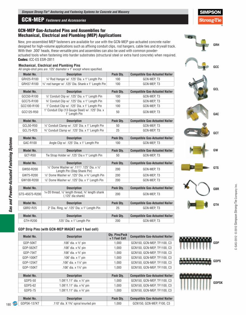
GCN-MEP Gas-Actuated Pins and Assemblies for Mechanical, Electrical and Plumbing (MEP) Applications New, pre-assembled MEP fasteners are available for use with the GCN-MEP gas-actuated concrete nailer designed for high-volume applications such as affixing conduit clips, rod hangers, cable ties and drywall track. With their .300" heads, these versatile pins and assemblies can also be used with common powder- actuated tools when fastening into harder substrates (structural steel or extra hard concrete) when required. Codes: ICC-ES ESR-2811
Mechanical, Electrical and Plumbing Pins All single-shot pins are .125" diameter x 1" except where specified.
Model No. Description Pack Qty. Compatible Gas-Actuated NailerGRH25-R100 1⁄4" Rod Hanger w/ .125" Dia. x 1" Length Pin 100 GCN-MEP, T3GRH37-R100 3⁄8" rod hanger w/ .125" Dia. Shank x 1" Length Pin 100 GCN-MEP, T3
Model No. Description Pack Qty. Compatible Gas-Actuated NailerGCC50-R100 1⁄2" Conduit Clip w/ .125" Dia. x 1" Length Pin 100 GCN-MEP, T3GCC75-R100 3⁄4" Conduit Clip w/ .125" Dia. x 1" Length Pin 100 GCN-MEP, T3
GCC100-R100 1" Conduit Clip w/ .125" Dia. x 1" Length Pin 100 GCN-MEP, T3
GCC125-R50 1" Conduit Clip (13 Gauge Steel) w/ .125" Dia. x 1" Length Pin 50 GCN-MEP, T3
Model No. Description Pack Qty. Compatible Gas-Actuated NailerGCL50-R50 1⁄2" Conduit Clamp w/ .125" Dia. x 1" Length Pin 50 GCN-MEP, T3GCL75-R25 3⁄4" Conduit Clamp w/ .125" Dia. x 1" Length Pin 25 GCN-MEP, T3
Model No. Description Pack Qty. Compatible Gas-Actuated NailerGAC-R100 Angle Clip w/ .125" Dia. x 1" Length Pin 100 GCN-MEP, T3
Model No. Description Pack Qty. Compatible Gas-Actuated NailerGCT-R50 Tie Strap Holder w/ .125" Dia x 1" Length Pin 50 GCN-MEP, T3
Model No. Description Pack Qty. Compatible Gas-Actuated Nailer
GW50-R2001⁄2" Dome Washer w/ .111"/ .125" Dia. x 1⁄2"
Length Pin (Step Shank Pin) 200 GCN-MEP, T3
GW75-R200 1⁄2" Dome Washer w/ .125" Dia. x 3⁄4" Length Pin 200 GCN-MEP, T3GW100-R200 1⁄2" Dome Washer w/ .125" Dia. x 1" Length Pin 200 GCN-MEP, T3
Model No. Description Pack Qty. Compatible Gas-Actuated Nailer
GTS-45075-R2001⁄4-20 thread, 1⁄2" length thread, 3⁄4" length shank
(.125" dia shank) 200 GCN-MEP, T3
Model No. Description Pack Qty. Compatible Gas-Actuated NailerGBR2-R25 2" Dia. Ring, w/ .125" Dia. x 1" Length Pin 25 GCN-MEP, T3
Model No. Description Pack Qty. Compatible Gas-Actuated Nailer GTH-R200 .125" Dia. x 1" Length Pin 200 GCN-MEP, T3
GRH
GCC
GCL
GAC
GCT
GW
GTS
GDP
GBR
GTH
GDP Strip Pins (with GCN-MEP MAGKT and 1 fuel cell)
Model No. Description Qty. Pins/Pack + 1 Fuel Cell Compatible Gas-Actuated Nailer
GDP-50KT .106" dia. x ½" pin 1,000 GCN150, GCN-MEP, TF1100, C3GDP-562KT .106" dia. x 5⁄8" pin 1,000 GCN150, GCN-MEP, TF1100, C3GDP-75KT .106" dia. x ¾" pin 1,000 GCN150, GCN-MEP, TF1100, C3GDP-100KT .106" dia. x 1" pin 1,000 GCN150, GCN-MEP, TF1100, C3GDP-125KT .106" dia. x 1¼" pin 1,000 GCN150, GCN-MEP, TF1100, C3GDP-150KT .106" dia. x 1½" pin 1,000 GCN150, GCN-MEP, TF1100, C3
Model No. Description Pack Qty. Compatible Gas-Actuated NailerGDPS-50 1.09"/1.11" dia. x ½" pin 1,000 GCN150, GCN-MEP, TF1100, C3GDPS-62 1.09"/1.11" dia. x 5⁄8" pin 1,000 GCN150, GCN-MEP, TF1100, C3GDPS-75 1.09"/1.11" dia. x ¾" pin 1,000 GCN150, GCN-MEP, TF1100, C3
Model No. Description Pack Qty. Compatible Gas-Actuated NailerGDPSK-137KT .110" dia. X 13⁄8" spiral knurled pin 1,000 GCN150, GCN-MEP, F100, C3
GDPS
GDPSK
NEW
GCN-MEP Fasteners and Accessories
Simpson Strong-Tie ® Anchoring and Fastening Systems for Concrete and MasonryC-
SAS-
2012
©20
12 S
imps
on S
trong
-Tie
Com
pany
Inc.
181
Gas and Powder-Actuated Fastening System
s
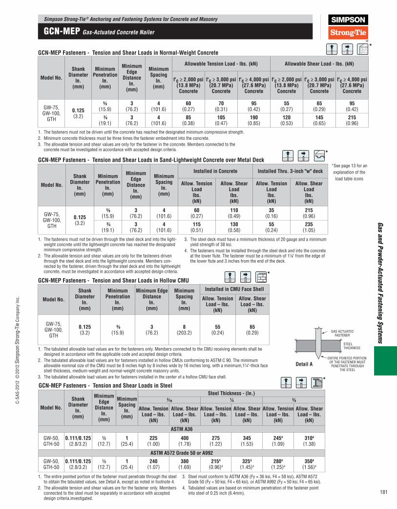
1. The entire pointed portion of the fastener must penetrate through the steel to obtain the tabulated values, see Detail A, except as noted in footnote 4.
2. The allowable tension and shear values are for the fastener only. Members connected to the steel must be separately in accordance with accepted design criteria.investigated.
3. Steel must conform to ASTM A36 (Fy = 36 ksi, F4 = 58 ksi), ASTM A572 Grade 50 (Fy = 50 ksi, F4 = 65 ksi), or ASTM A992 (Fy = 50 ksi, F4 = 65 ksi).
4. Tabulated values are based on minimum penetration of the fastener point into steel of 0.25 inch (6.4mm).
GCN-MEP Fasteners - Tension and Shear Loads in Steel
Model No.
Shank Diameter
In. (mm)
Minimum Edge
Distance In.
(mm)
Minimum Spacing
In. (mm)
Steel Thickness - (In.) 3⁄16 1⁄4 3⁄8
Allow. Tension Load – lbs.
(kN)
Allow. Shear Load – lbs.
(kN)
Allow. Tension Load – lbs.
(kN)
Allow. Shear Load – lbs.
(kN)
Allow. Tension Load – lbs.
(kN)
Allow. Shear Load – lbs.
(kN)
ASTM A36
GW-50, GTH-50
0.111/0.125 (2.8/3.2)
1⁄2 (12.7)
1 (25.4)
225 (1.00)
400 (1.78)
275 (1.22)
345 (1.53)
2454 (1.09)
3104 (1.38)
ASTM A572 Grade 50 or A992
GW-50, GTH-50
0.111/0.125 (2.8/3.2)
1⁄2 (12.7)
1 (25.4)
240 (1.07)
380 (1.69)
2154 (0.96)4
3254 (1.45)4
2804 (1.25)4
3504 (1.56)4
*
GAS ACTUATEDFASTENER
STEELTHICKNESS
ENTIRE POINTED PORTION OF THE FASTENER MUSTPENETRATE THROUGH
THE STEEL
1. The tabulated allowable load values are for the fasteners only. Members connected to the CMU receiving elements shall be designed in accordance with the applicable code and accepted design criteria.
2. The tabulated allowable load values are for fasteners installed in hollow CMUs conforming to ASTM C 90. The minimum allowable nominal size of the CMU must be 8 inches high by 8 inches wide by 16 inches long, with a minimum,1¼"-thick face shell thickness, medium-weight and normal-weight concrete masonry units.
3. The tabulated allowable load values are for fasteners installed in the center of a hollow CMU face shell.
GCN-MEP Fasteners - Tension and Shear Loads in Hollow CMU
Model No.
Shank Diameter
In. (mm)
Minimum Penetration
In. (mm)
Minimum Edge Distance
In. (mm)
Minimum Spacing
In. (mm)
Installed in CMU Face Shell
Allow. Tension Load – lbs.
(kN)
Allow. Shear Load – lbs.
(kN)
GW-75, GW-100,
GTH
0.125 (3.2)
5⁄8 (15.9)
3 (76.2)
8 (203.2)
55 (0.24)
65 (0.29)
*
GCN-MEP Fasteners - Tension and Shear Loads in Normal-Weight Concrete
Model No.
Shank Diameter
In. (mm)
Minimum Penetration
In. (mm)
Minimum Edge
Distance In.
(mm)
Minimum Spacing
In. (mm)
Allowable Tension Load - lbs. (kN) Allowable Shear Load - lbs. (kN)
f'c ≥ 2,000 psi (13.8 MPa) Concrete
f'c ≥ 3,000 psi (20.7 MPa) Concrete
f'c ≥ 4,000 psi (27.6 MPa) Concrete
f'c ≥ 2,000 psi (13.8 MPa) Concrete
f'c ≥ 3,000 psi (20.7 MPa) Concrete
f'c ≥ 4,000 psi (27.6 MPa) Concrete
GW-75,
GW-100, GTH
0.125 (3.2)
5⁄8
(15.9)3
(76.2)4
(101.6)60
(0.27)70
(0.31)95
(0.42)55
(0.27)65
(0.29)95
(0.42) 3⁄4
(19.1)3
(76.2)4
(101.6)85
(0.38)105
(0.47)190
(0.85)120
(0.53)145
(0.65)215
(0.96)
1. The fasteners must not be driven until the concrete has reached the designated minimum compressive strength. 2. Minimum concrete thickness must be three times the fastener embedment into the concrete. 3. The allowable tension and shear values are only for the fastener in the concrete. Members connected to the
concrete must be investigated in accordance with accepted design criteria.
*
1. The fasteners must not be driven through the steel deck and into the light-weight concrete until the lightweight concrete has reached the designated minimum compressive strength.
2. The allowable tension and shear values are only for the fasteners driven through the steel deck and into the lightweight concrete. Members con-nected by the fastener, driven through the steel deck and into the lightweight concrete, must be investigated in accordance with accepted design criteria.
3. The steel deck must have a minimum thickness of 20 gauge and a minimum yield strength of 38 ksi.
4. The fasteners must be installed through the steel deck and into the concrete at the lower flute. The fastener must be a minimum of 11⁄8" from the edge of the lower flute and 3 inches from the end of the deck.
GCN-MEP Fasteners - Tension and Shear Loads in Sand-Lightweight Concrete over Metal Deck
Model No.
Shank Diameter
In. (mm)
Minimum Penetration
In. (mm)
Minimum Edge
Distance In.
(mm)
Minimum Spacing
In. (mm)
Installed in Concrete Installed Thru. 3-inch "w" deck
Allow. Tension Load lbs. (kN)
Allow. Shear Load lbs. (kN)
Allow. Tension Load lbs. (kN)
Allow. Shear Load lbs. (kN)
GW-75,
GW-100, GTH
0.125 (3.2)
5⁄8
(15.9)3
(76.2)4
(101.6)60
(0.27)110
(0.49)35
(0.16)215
(0.96)
3⁄4
(19.1)3
(76.2)4
(101.6)115
(0.51)130
(0.58)55
(0.24)235
(1.05)
*
Detail A
*See page 13 for an explanation of the load table icons
GCN-MEP Gas-Actuated Concrete Nailer
ICC-ES Evaluation Reports are not to be construed as representing aesthetics or any other attributes not specifically addressed, nor are they to be construed as an endorsement of the subject of the report or a recommendation for its use. There is no warranty by ICC Evaluation Service, LLC, express or implied, as to any finding or other matter in this report, or as to any product covered by the report.
Copyright © 2014 Page 1 of 8 1000
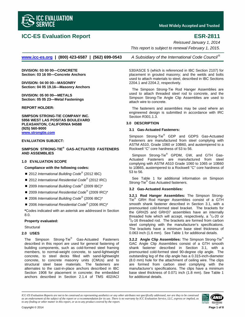
ICC-ES Evaluation Report ESR-2811 Reissued January 1, 2014
This report is subject to renewal February 1, 2015.
www.icc-es.org | (800) 423-6587 | (562) 699-0543 A Subsidiary of the International Code Council ®
DIVISION: 03 00 00—CONCRETE Section: 03 16 00—Concrete Anchors DIVISION: 04 00 00—MASONRY Section: 04 05 19.16—Masonry Anchors DIVISION: 05 00 00—METALS Section: 05 05 23—Metal Fastenings REPORT HOLDER: SIMPSON STRONG-TIE COMPANY INC. 5956 WEST LAS POSITAS BOULEVARD PLEASANTON, CALIFORNIA 94588 (925) 560-9000 www.strongtie.com EVALUATION SUBJECT: SIMPSON STRONG-TIE® GAS-ACTUATED FASTENERS AND ASSEMBLIES 1.0 EVALUATION SCOPE
Compliance with the following codes:
2012 International Building Code® (2012 IBC) 2012 International Residential Code® (2012 IRC) 2009 International Building Code® (2009 IBC)*
2009 International Residential Code® (2009 IRC)*
2006 International Building Code® (2006 IBC)*
2006 International Residential Code® (2006 IRC)*
*Codes indicated with an asterisk are addressed in Section 8.0.
Property evaluated:
Structural
2.0 USES
The Simpson Strong-Tie® Gas-Actuated Fasteners described in this report are used for general fastening of building components, such as cold-formed steel framing members, to normal-weight concrete, to sand-lightweight concrete, to steel decks filled with sand-lightweight concrete, to concrete masonry units (CMUs) and to structural steel base materials. The fasteners are alternates to the cast-in-place anchors described in IBC Section 1908 for placement in concrete; the embedded anchors described in Section 2.1.4 of TMS 402/ACI
530/ASCE 5 (which is referenced in IBC Section 2107) for placement in grouted masonry; and the welds and bolts used to attach materials to steel, described in IBC Sections 2204.1 and 2204.2, respectively.
The Simpson Strong-Tie Rod Hanger Assemblies are used to attach threaded steel rod to concrete, and the Simpson Strong-Tie Angle Clip Assemblies are used to attach wire to concrete.
The fasteners and assemblies may be used where an engineered design is submitted in accordance with IRC Section R301.1.3.
3.0 DESCRIPTION
3.1 Gas-Actuated Fasteners:
Simpson Strong-Tie® GDP and GDPS Gas-Actuated Fasteners are manufactured from steel complying with ASTM A510, Grade 1060 or 10B60, and austempered to a Rockwell “C” core hardness of 53 to 56.
Simpson Strong-Tie® GPDM, GW, and GTH Gas-Actuated Fasteners are manufactured from steel complying with ASTM A510 Grade 1060 to 1065 or 10B60 to 10B65, austempered to a Rockwell "C" core hardness of 53 to 56.
See Table 1 for additional information on Simpson Strong-Tie® Gas Actuated fasteners.
3.2 Gas-Actuated Assemblies:
3.2.1 Rod Hanger Assemblies: The Simpson Strong-Tie® GRH Rod Hanger Assemblies consist of a GTH smooth shank fastener described in Section 3.1, with a premounted cold-formed steel bracket. The brackets for the GRH25 and GRH37 assemblies have an internally threaded hole which will accept, respectively, a 1/4-20 or 3/8-16 threaded rod. The brackets are formed from carbon steel complying with the manufacturer’s specifications. The brackets have a minimum base steel thickness of 0.063 inch (1.6 mm). See Table 1 for additional details.
3.2.2 Angle Clip Assemblies: The Simpson Strong-Tie® GAC Angle Clip Assemblies consist of a GTH smooth shank fastener described in Section 3.1, with a premounted cold-formed steel 90-degree clip angle. The outstanding leg of the clip angle has a 0.315-inch-diameter (8.0 mm) hole for the attachment of ceiling wire. The clips are formed from carbon steel complying with the manufacturer’s specifications. The clips have a minimum base steel thickness of 0.071 inch (1.8 mm). See Table 1 for additional details.
ESR-2811 | Most Widely Accepted and Trusted Page 2 of 8
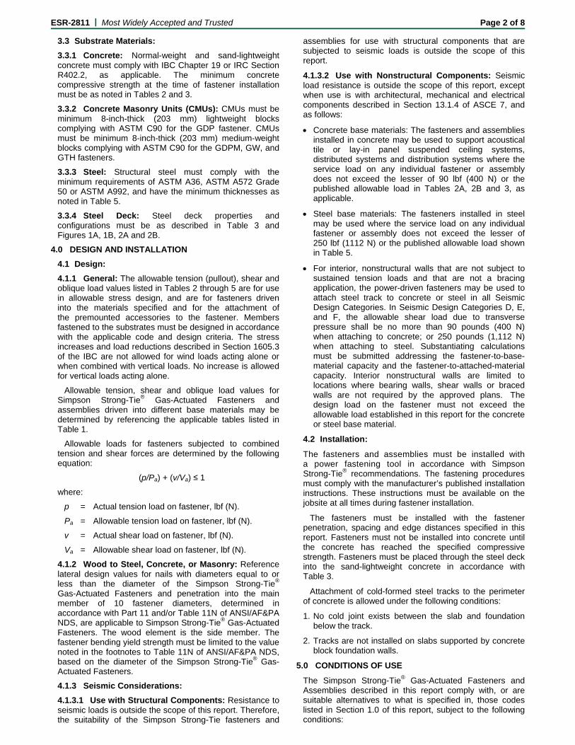
3.3 Substrate Materials:
3.3.1 Concrete: Normal-weight and sand-lightweight concrete must comply with IBC Chapter 19 or IRC Section R402.2, as applicable. The minimum concrete compressive strength at the time of fastener installation must be as noted in Tables 2 and 3.
3.3.2 Concrete Masonry Units (CMUs): CMUs must be minimum 8-inch-thick (203 mm) lightweight blocks complying with ASTM C90 for the GDP fastener. CMUs must be minimum 8-inch-thick (203 mm) medium-weight blocks complying with ASTM C90 for the GDPM, GW, and GTH fasteners.
3.3.3 Steel: Structural steel must comply with the minimum requirements of ASTM A36, ASTM A572 Grade 50 or ASTM A992, and have the minimum thicknesses as noted in Table 5.
3.3.4 Steel Deck: Steel deck properties and configurations must be as described in Table 3 and Figures 1A, 1B, 2A and 2B.
4.0 DESIGN AND INSTALLATION
4.1 Design:
4.1.1 General: The allowable tension (pullout), shear and oblique load values listed in Tables 2 through 5 are for use in allowable stress design, and are for fasteners driven into the materials specified and for the attachment of the premounted accessories to the fastener. Members fastened to the substrates must be designed in accordance with the applicable code and design criteria. The stress increases and load reductions described in Section 1605.3 of the IBC are not allowed for wind loads acting alone or when combined with vertical loads. No increase is allowed for vertical loads acting alone.
Allowable tension, shear and oblique load values for Simpson Strong-Tie® Gas-Actuated Fasteners and assemblies driven into different base materials may be determined by referencing the applicable tables listed in Table 1.
Allowable loads for fasteners subjected to combined tension and shear forces are determined by the following equation:
(p/Pa) + (v/Va) ≤ 1
where:
p = Actual tension load on fastener, lbf (N).
Pa = Allowable tension load on fastener, lbf (N).
v = Actual shear load on fastener, lbf (N).
Va = Allowable shear load on fastener, lbf (N).
4.1.2 Wood to Steel, Concrete, or Masonry: Reference lateral design values for nails with diameters equal to or less than the diameter of the Simpson Strong-Tie®
Gas-Actuated Fasteners and penetration into the main member of 10 fastener diameters, determined in accordance with Part 11 and/or Table 11N of ANSI/AF&PA NDS, are applicable to Simpson Strong-Tie® Gas-Actuated Fasteners. The wood element is the side member. The fastener bending yield strength must be limited to the value noted in the footnotes to Table 11N of ANSI/AF&PA NDS, based on the diameter of the Simpson Strong-Tie® Gas-Actuated Fasteners.
4.1.3 Seismic Considerations:
4.1.3.1 Use with Structural Components: Resistance to seismic loads is outside the scope of this report. Therefore, the suitability of the Simpson Strong-Tie fasteners and
assemblies for use with structural components that are subjected to seismic loads is outside the scope of this report.
4.1.3.2 Use with Nonstructural Components: Seismic load resistance is outside the scope of this report, except when use is with architectural, mechanical and electrical components described in Section 13.1.4 of ASCE 7, and as follows:
Concrete base materials: The fasteners and assemblies installed in concrete may be used to support acoustical tile or lay-in panel suspended ceiling systems, distributed systems and distribution systems where the service load on any individual fastener or assembly does not exceed the lesser of 90 lbf (400 N) or the published allowable load in Tables 2A, 2B and 3, as applicable.
Steel base materials: The fasteners installed in steel may be used where the service load on any individual fastener or assembly does not exceed the lesser of 250 lbf (1112 N) or the published allowable load shown in Table 5.
For interior, nonstructural walls that are not subject to sustained tension loads and that are not a bracing application, the power-driven fasteners may be used to attach steel track to concrete or steel in all Seismic Design Categories. In Seismic Design Categories D, E, and F, the allowable shear load due to transverse pressure shall be no more than 90 pounds (400 N) when attaching to concrete; or 250 pounds (1,112 N) when attaching to steel. Substantiating calculations must be submitted addressing the fastener-to-base- material capacity and the fastener-to-attached-material capacity. Interior nonstructural walls are limited to locations where bearing walls, shear walls or braced walls are not required by the approved plans. The design load on the fastener must not exceed the allowable load established in this report for the concrete or steel base material.
4.2 Installation:
The fasteners and assemblies must be installed with a power fastening tool in accordance with Simpson Strong-Tie® recommendations. The fastening procedures must comply with the manufacturer’s published installation instructions. These instructions must be available on the jobsite at all times during fastener installation.
The fasteners must be installed with the fastener penetration, spacing and edge distances specified in this report. Fasteners must not be installed into concrete until the concrete has reached the specified compressive strength. Fasteners must be placed through the steel deck into the sand-lightweight concrete in accordance with Table 3.
Attachment of cold-formed steel tracks to the perimeter of concrete is allowed under the following conditions:
1. No cold joint exists between the slab and foundation below the track.
2. Tracks are not installed on slabs supported by concrete block foundation walls.
5.0 CONDITIONS OF USE
The Simpson Strong-Tie® Gas-Actuated Fasteners and Assemblies described in this report comply with, or are suitable alternatives to what is specified in, those codes listed in Section 1.0 of this report, subject to the following conditions:

ESR-2811 | Most Widely Accepted and Trusted Page 3 of 8
5.1 The fasteners are manufactured and identified in accordance with this report.
5.2 Fastener installation complies with this report and the Simpson Strong-Tie® published installation instructions. In the event of conflict between this report and the Simpson Strong-Tie® published installation instructions, this report governs.
5.3 Allowable tension, shear and oblique load values are as noted in Tables 2 through 5. The stress increases and load reductions described in Section 1605.3 of the IBC are not allowed for wind loads acting alone or when combined with vertical loads. No increase is allowed for vertical loads acting alone.
5.4 Calculations demonstrating that the applied loads are less than the allowable loads described in this report must be submitted to the code official for approval. The calculations are to be prepared by a registered design professional where required by the statutes of the jurisdiction in which the project is to be constructed.
5.5 The minimum concrete thickness must be three times the fastener penetration depth. Face shell thickness of CMUs must be a minimum of 11/4 inches (32 mm).
5.6 Refer to Section 4.1.3 for seismic considerations.
5.7 The use of fasteners is limited to installation in uncracked concrete or masonry. Cracking occurs when ft > fr due to service loads or deformations.
5.8 Use of fasteners is limited to dry, interior locations.
5.9 Use of fasteners in contact with preservative-treated or fire-retardant-treated wood is not permitted.
6.0 EVIDENCE SUBMITTED
Data in accordance with the ICC-ES Acceptance Criteria for Fasteners Power-driven into Concrete, Steel and Masonry Elements (AC70), dated February 2013.
7.0 IDENTIFICATION
Containers of fasteners and assemblies are identified with the manufacturer’s name (Simpson Strong-Tie®), the product name, the fastener catalog number, the length, the quantity, the manufacturing date and the evaluation report number (ESR-2811). In addition, each fastener is identified by ≠ (the “no equal” sign) stamped on the fastener head.
8.0 OTHER CODES
8.1 Scope:
In addition to the 2012 IBC and IRC, the products described in this report were evaluated for compliance with the requirements of the following codes:
2009 International Building Code® (2009 IBC) 2009 International Residential Code® (2009 IRC) 2006 International Building Code® (2006 IBC)
2006 International Residential Code® (2006 IRC)
8.2 Uses:
Simpson Strong-Tie® Gas-Actuated Fasteners and Assemblies are used for general fastening of building components as described in Section 2.0. The fasteners are alternates to the cast-in-place anchors described in 2009 and 2006 IBC Sections 1911 and 1912 for placement in concrete; the embedded anchors described in Section 2.1.4 of TMS 402/ACI 530/ASCE 5 (which is referenced in IBC Section 2107) for placement in grouted masonry; and the welds and bolts used to attach materials to steel, described in IBC Sections 2204.1 and 2204.2, respectively. The fasteners may be used where an engineered design is submitted in accordance with 2009 and 2006 IRC Section R301.1.3.
8.3 Description:
8.3.1 Fasteners: See Section 3.1.
8.3.2 Assemblies: See Section 3.2.
8.3.3 Materials:
8.3.3.1 Concrete: See Section 3.3.1.
8.3.3.2 Steel: See Section 3.3.3.
8.3.3.3 Steel Deck: See Section 3.3.4.
8.4 Design and Installation:
8.4.1 Design:
8.4.1.1 General: See Section 4.1.
8.4.1.2 Wood to Steel, Concrete, or Masonry: For the 2009 IBC, 2009 IRC, 2006 IBC and 2006 IRC, see Section 4.1.2.
8.4.1.3 Seismic Considerations: See Section 4.1.3.
8.4.2 Installation: See Section 4.2.
8.5 Conditions of Use:
See Section 5.0, and the following:
Allowable tension and shear values are as noted in Tables 2 through 5. The stress increases and load reductions described in Section 1605.3 of the 2009 and 2006, are not allowed for wind loads acting alone or when combined with vertical loads. No increase is allowed for vertical loads acting alone.
8.6 Evidence Submitted:
See Section 6.0.
8.7 Identification:
See Section 7.0.
ESR-2811 | Most Widely Accepted and Trusted Page 4 of 8
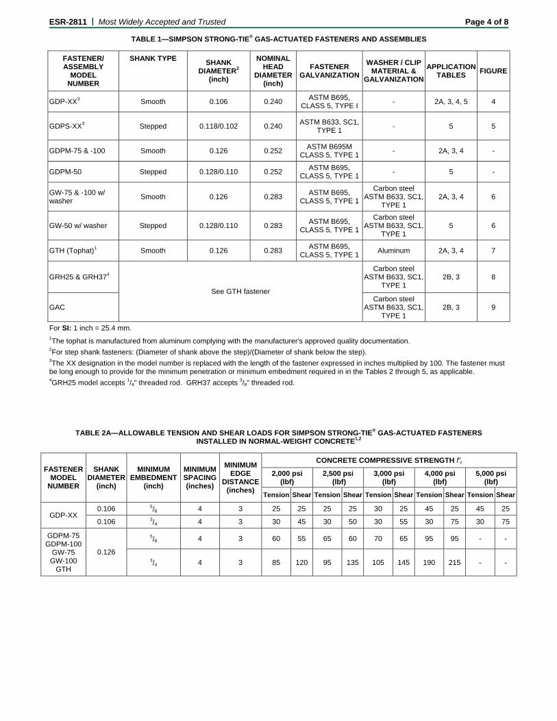
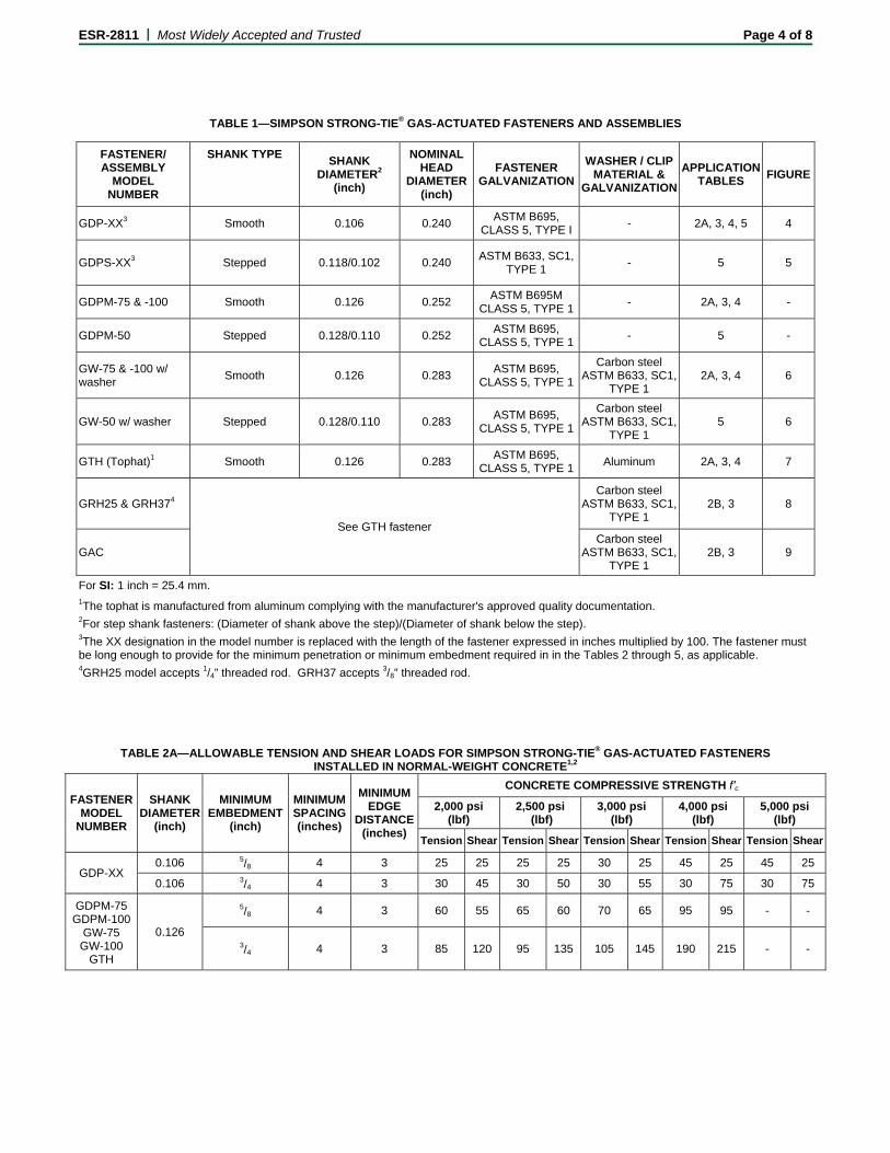
TABLE 1—SIMPSON STRONG-TIE® GAS-ACTUATED FASTENERS AND ASSEMBLIES
FASTENER/ ASSEMBLY
MODEL NUMBER
SHANK TYPE SHANK
DIAMETER2 (inch)
NOMINAL HEAD
DIAMETER (inch)
FASTENER GALVANIZATION
WASHER / CLIP MATERIAL &
GALVANIZATION
APPLICATION TABLES
FIGURE
GDP-XX3 Smooth 0.106 0.240 ASTM B695,
CLASS 5, TYPE I - 2A, 3, 4, 5 4
GDPS-XX3 Stepped 0.118/0.102 0.240 ASTM B633, SC1,
TYPE 1 - 5 5
GDPM-75 & -100 Smooth 0.126 0.252 ASTM B695M
CLASS 5, TYPE 1- 2A, 3, 4 -
GDPM-50 Stepped 0.128/0.110 0.252 ASTM B695,
CLASS 5, TYPE 1- 5 -
GW-75 & -100 w/ washer
Smooth 0.126 0.283 ASTM B695,
CLASS 5, TYPE 1
Carbon steel ASTM B633, SC1,
TYPE 1 2A, 3, 4 6
GW-50 w/ washer Stepped 0.128/0.110 0.283 ASTM B695,
CLASS 5, TYPE 1
Carbon steel ASTM B633, SC1,
TYPE 1 5 6
GTH (Tophat)1 Smooth 0.126 0.283 ASTM B695,
CLASS 5, TYPE 1Aluminum 2A, 3, 4 7
GRH25 & GRH374
See GTH fastener
Carbon steel ASTM B633, SC1,
TYPE 1 2B, 3 8
GAC Carbon steel
ASTM B633, SC1, TYPE 1
2B, 3 9
For SI: 1 inch = 25.4 mm. 1The tophat is manufactured from aluminum complying with the manufacturer's approved quality documentation. 2For step shank fasteners: (Diameter of shank above the step)/(Diameter of shank below the step). 3The XX designation in the model number is replaced with the length of the fastener expressed in inches multiplied by 100. The fastener must be long enough to provide for the minimum penetration or minimum embedment required in in the Tables 2 through 5, as applicable. 4GRH25 model accepts 1/4" threaded rod. GRH37 accepts 3/8" threaded rod.
TABLE 2A—ALLOWABLE TENSION AND SHEAR LOADS FOR SIMPSON STRONG-TIE® GAS-ACTUATED FASTENERS
INSTALLED IN NORMAL-WEIGHT CONCRETE1,2
FASTENER MODEL
NUMBER
SHANK DIAMETER
(inch)
MINIMUM EMBEDMENT
(inch)
MINIMUM SPACING (inches)
MINIMUM EDGE
DISTANCE (inches)
CONCRETE COMPRESSIVE STRENGTH f′c
2,000 psi (lbf)
2,500 psi (lbf)
3,000 psi (lbf)
4,000 psi (lbf)
5,000 psi (lbf)
Tension Shear Tension Shear Tension Shear Tension Shear Tension Shear
GDP-XX 0.106 5/8 4 3 25 25 25 25 30 25 45 25 45 25
0.106 3/4 4 3 30 45 30 50 30 55 30 75 30 75
GDPM-75 GDPM-100
GW-75 GW-100
GTH
0.126
5/8 4 3 60 55 65 60 70 65 95 95 - -
3/4 4 3 85 120 95 135 105 145 190 215 - -
ESR-2811 | Most Widely Accepted and Trusted Page 5 of 8
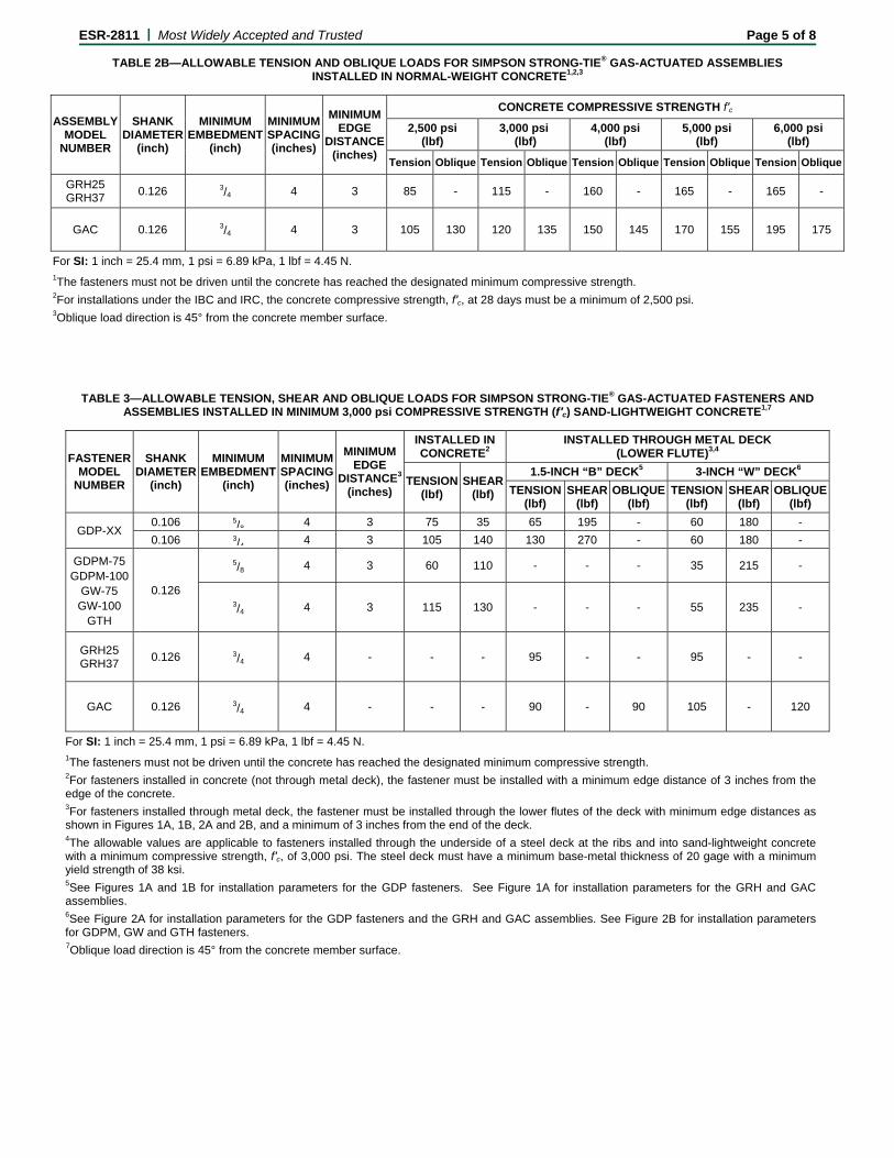
TABLE 2B—ALLOWABLE TENSION AND OBLIQUE LOADS FOR SIMPSON STRONG-TIE® GAS-ACTUATED ASSEMBLIES INSTALLED IN NORMAL-WEIGHT CONCRETE1,2,3
ASSEMBLY MODEL
NUMBER
SHANK DIAMETER
(inch)
MINIMUM EMBEDMENT
(inch)
MINIMUM SPACING (inches)
MINIMUM EDGE
DISTANCE (inches)
CONCRETE COMPRESSIVE STRENGTH f′c
2,500 psi (lbf)
3,000 psi (lbf)
4,000 psi (lbf)
5,000 psi (lbf)
6,000 psi (lbf)
Tension Oblique Tension Oblique Tension Oblique Tension Oblique Tension Oblique
GRH25 GRH37
0.126 3/4 4 3 85 - 115 - 160 - 165 - 165 -
GAC 0.126 3/4 4 3 105 130 120 135 150 145 170 155 195 175
For SI: 1 inch = 25.4 mm, 1 psi = 6.89 kPa, 1 lbf = 4.45 N. 1The fasteners must not be driven until the concrete has reached the designated minimum compressive strength. 2For installations under the IBC and IRC, the concrete compressive strength, f′c, at 28 days must be a minimum of 2,500 psi. 3Oblique load direction is 45° from the concrete member surface.
TABLE 3—ALLOWABLE TENSION, SHEAR AND OBLIQUE LOADS FOR SIMPSON STRONG-TIE® GAS-ACTUATED FASTENERS AND
ASSEMBLIES INSTALLED IN MINIMUM 3,000 psi COMPRESSIVE STRENGTH (f′c) SAND-LIGHTWEIGHT CONCRETE1,7
FASTENER MODEL
NUMBER
SHANK DIAMETER
(inch)
MINIMUM EMBEDMENT
(inch)
MINIMUM SPACING (inches)
MINIMUM EDGE
DISTANCE3
(inches)
INSTALLED IN CONCRETE2
INSTALLED THROUGH METAL DECK (LOWER FLUTE)3,4
TENSION(lbf)
SHEAR(lbf)
1.5-INCH “B” DECK5 3-INCH “W” DECK6
TENSION(lbf)
SHEAR(lbf)
OBLIQUE (lbf)
TENSION(lbf)
SHEAR(lbf)
OBLIQUE(lbf)
GDP-XX 0.106 5/8 4 3 75 35 65 195 - 60 180 -
0.106 3/4 4 3 105 140 130 270 - 60 180 -
GDPM-75 GDPM-100
GW-75 GW-100
GTH
0.126
5/8 4 3 60 110 - - - 35 215 -
3/4 4 3 115 130 - - - 55 235 -
GRH25 GRH37
0.126 3/4 4 - - - 95 - - 95 - -
GAC 0.126 3/4 4 - - - 90 - 90 105 - 120
For SI: 1 inch = 25.4 mm, 1 psi = 6.89 kPa, 1 lbf = 4.45 N. 1The fasteners must not be driven until the concrete has reached the designated minimum compressive strength. 2For fasteners installed in concrete (not through metal deck), the fastener must be installed with a minimum edge distance of 3 inches from the edge of the concrete. 3For fasteners installed through metal deck, the fastener must be installed through the lower flutes of the deck with minimum edge distances as shown in Figures 1A, 1B, 2A and 2B, and a minimum of 3 inches from the end of the deck. 4The allowable values are applicable to fasteners installed through the underside of a steel deck at the ribs and into sand-lightweight concrete with a minimum compressive strength, f′c, of 3,000 psi. The steel deck must have a minimum base-metal thickness of 20 gage with a minimum yield strength of 38 ksi. 5See Figures 1A and 1B for installation parameters for the GDP fasteners. See Figure 1A for installation parameters for the GRH and GAC assemblies. 6See Figure 2A for installation parameters for the GDP fasteners and the GRH and GAC assemblies. See Figure 2B for installation parameters for GDPM, GW and GTH fasteners. 7Oblique load direction is 45° from the concrete member surface.
ESR-2811 | Most Widely Accepted and Trusted Page 6 of 8
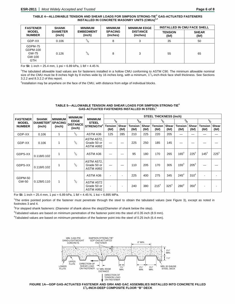
TABLE 4—ALLOWABLE TENSION AND SHEAR LOADS FOR SIMPSON STRONG-TIE® GAS-ACTUATED FASTENERS INSTALLED IN CONCRETE MASONRY UNITS (CMUs)1,2
FASTENER MODEL
NUMBER
SHANK DIAMETER
(inch)
MINIMUM EMBEDMENT
(inch)
MINIMUM SPACING (inches)
MINIMUM EDGE DISTANCE
(inches)
INSTALLED IN CMU FACE SHELL
TENSION (lbf)
SHEAR (lbf)
GDP-XX 0.106 5/8 8 3 35 50
GDPM-75 GDPM-100
GW-75 GW-100
GTH
0.126 5/8 8 3 55 65
For SI: 1 inch = 25.4 mm, 1 psi = 6.89 kPa, 1 lbf = 4.45 N. 1The tabulated allowable load values are for fasteners installed in a hollow CMU conforming to ASTM C90. The minimum allowable nominal size of the CMU must be 8 inches high by 8 inches wide by 16 inches long, with a minimum, 11/4-inch-thick face shell thickness. See Sections 3.2.2 and 8.3.2.2 of this report. 2Installation may be anywhere on the face of the CMU, with distance from edge of individual blocks.
TABLE 5—ALLOWABLE TENSION AND SHEAR LOADS FOR SIMPSON STRONG-TIE® GAS-ACTUATED FASTENERS INSTALLED IN STEEL1
FASTENER MODEL
NUMBER
SHANK DIAMETER2
(inch)
MINIMUM SPACING
(inch)
MINIMUM EDGE
DISTANCE (inch)
MINIMUM STEEL
STRENGTH4
STEEL THICKNESS (inch) 1/8
3/16 1/4
3/8 1/2
Tension(lbf)
Shear(lbf)
Tension(lbf)
Shear(lbf)
Tension(lbf)
Shear (lbf)
Tension (lbf)
Shear(lbf)
Tension(lbf)
Shear(lbf)
GDP-XX 0.106 1 1/2 ASTM A36 125 285 210 225 220 205 — — — —
GDP-XX 0.106 1 1/2 ASTM A572, Grade 50 or ASTM A992
— — 225 250 185 145 — — — —
GDPS-XX
0.118/0.102 1 1/2 ASTM A36 — — 95 180 170 265 1653 2253 1453 2253
GDPS-XX
0.118/0.102 1 1/2
ASTM A572, Grade 50 or ASTM A992
— — 110 205 170 305 1553 2053 — —
GDPM-50 GW-50
0.128/0.110 1 1/2
ASTM A36 - - 225 400 275 345 2454 3104 - -
ASTM A572 Grade 50 or ASTM A992
- - 240 380 2154 3254 2804 3504 - -
For SI: 1 inch = 25.4 mm, 1 psi = 6.89 kPa, 1 lbf = 4.45 N, 1 ksi = 6.895 MPa. 1The entire pointed portion of the fastener must penetrate through the steel to obtain the tabulated values (see Figure 3), except as noted in footnotes 3 and 4. 2For stepped shank fasteners: (Diameter of shank above the step)/(Diameter of shank below the step). 3Tabulated values are based on minimum penetration of the fastener point into the steel of 0.35 inch (8.9 mm). 4Tabulated values are based on minimum penetration of the fastener point into the steel of 0.25 inch (6.4 mm).
FIGURE 1A—GDP GAS-ACTUATED FASTENER AND GRH AND GAC ASSEMBLIES INSTALLED INTO CONCRETE FILLED
11/2-INCH-DEEP COMPOSITE FLOOR “B” DECK

ESR-2811 | Most Widely Accepted and Trusted Page 7 of 8
FIGURE 1B—GDP GAS-ACTUATED FASTENER INSTALLED INTO CONCRETE FILLED INVERTED 11/2-INCH-DEEP COMPOSITE FLOOR “B” DECK
FIGURE 2A—GDP GAS-ACTUATED FASTENER AND GRH AND GAC ASSEMBLIES INSTALLED IN CONCRETE FILLED 3-INCH-DEEP
COMPOSITE FLOOR “W” DECK
FIGURE 2B—GDPM, GW & GTH GAS-ACTUATED FASTENER INSTALLED IN CONCRETE FILLED 3-INCH-DEEP COMPOSITE FLOOR “W” DECK
FIGURE 3—FASTENER PENETRATION THROUGH STEEL WHERE REQUIRED
ESR-2811 | Most Widely Accepted and Trusted Page 8 of 8
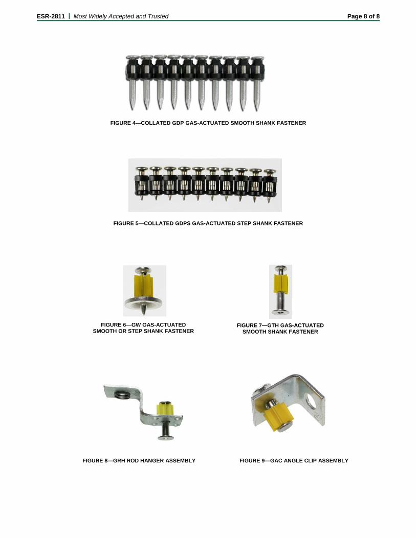
FIGURE 4—COLLATED GDP GAS-ACTUATED SMOOTH SHANK FASTENER
FIGURE 5—COLLATED GDPS GAS-ACTUATED STEP SHANK FASTENER
FIGURE 7—GTH GAS-ACTUATED SMOOTH SHANK FASTENER
FIGURE 6—GW GAS-ACTUATED SMOOTH OR STEP SHANK FASTENER
FIGURE 8—GRH ROD HANGER ASSEMBLY FIGURE 9—GAC ANGLE CLIP ASSEMBLY
BOARD OF
BUILDING AND SAFETY COMMISSIONERS
___
HELENA JUBANY PRESIDENT
VAN AMBATIELOS VICE-PRESIDENT
E. FELICIA BRANNON VICTOR H. CUEVAS
GEORGE HOVAGUIMIAN
___
CITY OF LOS ANGELESCALIFORNIA
ERIC GARCETTI MAYOR
DEPARTMENT OF
BUILDING AND SAFETY 201 NORTH FIGUEROA STREET
LOS ANGELES, CA 90012
____
RAYMOND S. CHAN, C.E., S.E.
SUPERINTENDENT OF BUILDING INTERIM GENERAL MANAGER
____
RR 25837 Page 1 of 3
LADBS G-5 (Rev.02/20/2014) AN EQUAL EMPLOYMENT OPPORTUNITY - AFFIRMATIVE ACTION EMPLOYER
Simpson Strong-Tie Co., Inc. RESEARCH REPORT: RR 25837 12246 Holly Street (CSI # 03 16 00) Riverside, CA 92509
BASED UPON ICC ES EVALUATION Attn: Jason M. Oakley REPORT NO. ESR-2811
(714) 448-9143 REEVALUATION DUE DATE: November 1, 2016 Issued Date: April 1, 2014
Code: 2014 LABC GENERAL APPROVAL – Reevaluation-Simpson Strong-Tie® GDP and GDPS Gas Actuated Fasteners.
DETAILS
The above assemblies and/or products are approved when in compliance with the description, use, identification and findings of Report No. ESR-2811, reissued January 1, 2014, of the ICC Evaluation Service, Incorporated. The report, in its entirety, is attached and made part of this general approval.
The parts of Report No. ESR-2811 which are excluded on the attached copy have been removed by the Los Angeles City Building Department as not being included in this approval.
The approval is subject to the following conditions:
1. Powder-Driven Fasteners are not allowed to resist earthquake forces except as described in Section 4.1.3.2 of ESR-2811.
2. Powder-Driven Fasteners must be installed in accordance with this report and Simpson Strong-Tie published installation instructions. A copy of the manufacturer’s installation instructions shall be available at the job site.
3. Powder-Driven Fasteners must not be used in preservative-treated wood or fire-retardant treated wood.
Simpson Strong-Tie Company, Inc. RE: Simpson Strong-Tie® GDP and GDPS Gas Actuated Fasteners.
RR 25837 Page 2 of 3
4. Installation is limited to dry, interior environments. 5. Calculations demonstrating that the applied loads are less than the maximum allowable
loads must be submitted with plans and details to Structural Plan Check. The calculations must be prepared by a California registered Civil or Structural Engineer.
6. For fasteners installed into concrete, the minimum concrete thickness must be three times
the fastener embedment in concrete. 7. Use of fasteners is limited to uncracked concrete and masonry. 8. For working values in steel, the fasteners shall have sufficient length so that the entire
pointed portion of the shank pierces the steel plate. 9. The allowable values listed in the attached report and tables are for the fasteners only.
Connected members shall be checked for their capacity (which may govern). 10. Fasteners used in structural light weight concrete filled steel deck applications are limited
to installation in the lower flute or top surface as shown on Figures 1A, 1B, and 2 of ESR 2811
11. No increase is permitted in the tabulated allowable load values for short duration loading. 12. The containers of the fasteners shall be labeled with the Simpson Strong-Tie name; the
fastener product name, length, catalog number, and quantity; the evaluation report number (ESR-2811); and the manufacturing date and lot number
DISCUSSION
The report is in compliance with the 2014 Los Angeles City Building Code.
The Approval is based on and in accordance with the ICC-Acceptance Criteria AC 70.
This general approval will remain effective provided the Evaluation Report is maintained valid and unrevised with the issuing organization. Any revisions to the report must be submitted to this Department for review with appropriate fee to continue the approval of the revised report.
Addressee to whom this Research Report is issued is responsible for providing copies of it, complete with any attachments indicated, to architects, engineers and builders using items approved herein in design or construction which must be approved by Department of Building and Safety Engineers and Inspectors.

Simpson Strong-Tie Company, Inc. RE: Simpson Strong-Tie® GDP and GDPS Gas Actuated Fasteners.
RR 25837 Page 3 of 3
This general approval of an equivalent alternate to the Code is only valid where an engineer and/or inspector of this Department has determined that all conditions of this Approval have been met in the project in which it is to be used.
____________________________________ ALLEN PEERY, Chief Engineering Research Section 201 N. Figueroa St., Room 880 Los Angeles, CA 90012 Phone- 213-202-9812 Fax- 213-202-9943 KH RR25837/MSWord2010 R03/13/14 5A1/5C2/1911/2107/104.11
Attachment: ICC-ES Evaluation Report No. ESR-2811 (8 pages)

ICC-ES Evaluation Reports are not to be construed as representing aesthetics or any other attributes not specifically addressed, nor are they to be construed as an endorsement of the subject of the report or a recommendation for its use. There is no warranty by ICC Evaluation Service, LLC, express or implied, as to any finding or other matter in this report, or as to any product covered by the report.
Copyright © 2014 Page 1 of 8 1000
ICC-ES Evaluation Report ESR-2811 Reissued January 1, 2014 This report is subject to renewal February 1, 2015.
www.icc-es.org | (800) 423-6587 | (562) 699-0543 A Subsidiary of the International Code Council ®
DIVISION: 03 00 00—CONCRETE Section: 03 16 00—Concrete Anchors DIVISION: 04 00 00—MASONRY Section: 04 05 19.16—Masonry Anchors DIVISION: 05 00 00—METALS Section: 05 05 23—Metal Fastenings REPORT HOLDER: SIMPSON STRONG-TIE COMPANY INC. 5956 WEST LAS POSITAS BOULEVARD PLEASANTON, CALIFORNIA 94588 (925) 560-9000 www.strongtie.com EVALUATION SUBJECT: SIMPSON STRONG-TIE® GAS-ACTUATED FASTENERS AND ASSEMBLIES 1.0 EVALUATION SCOPE
Compliance with the following codes:
2012 International Building Code® (2012 IBC) 2012 International Residential Code® (2012 IRC) 2009 International Building Code® (2009 IBC)*
2009 International Residential Code® (2009 IRC)*
2006 International Building Code® (2006 IBC)*
2006 International Residential Code® (2006 IRC)*
2003 International Building Code® (2003 IBC)*
2003 International Residential Code® (2003 IRC)*
1997 Uniform Building Code™ (UBC)*
*Codes indicated with an asterisk are addressed in Section 8.0.
Property evaluated:
Structural
2.0 USES
The Simpson Strong-Tie® Gas-Actuated Fasteners described in this report are used for general fastening of building components, such as cold-formed steel framing members, to normal-weight concrete, to sand-lightweight concrete, to steel decks filled with sand-lightweight concrete, to concrete masonry units (CMUs) and to
structural steel base materials. The fasteners are alternates to the cast-in-place anchors described in IBC Section 1908 for placement in concrete; the embedded anchors described in Section 2.1.4 of TMS 402/ACI 530/ASCE 5 (which is referenced in IBC Section 2107) for placement in grouted masonry; and the welds and bolts used to attach materials to steel, described in IBC Sections 2204.1 and 2204.2, respectively.
The Simpson Strong-Tie Rod Hanger Assemblies are used to attach threaded steel rod to concrete, and the Simpson Strong-Tie Angle Clip Assemblies are used to attach wire to concrete.
The fasteners and assemblies may be used where an engineered design is submitted in accordance with IRC Section R301.1.3.
3.0 DESCRIPTION
3.1 Gas-Actuated Fasteners:
Simpson Strong-Tie® GDP and GDPS Gas-Actuated Fasteners are manufactured from steel complying with ASTM A510, Grade 1060 or 10B60, and austempered to a Rockwell “C” core hardness of 53 to 56.
Simpson Strong-Tie® GPDM, GW, and GTH Gas-Actuated Fasteners are manufactured from steel complying with ASTM A510 Grade 1060 to 1065 or 10B60 to 10B65, austempered to a Rockwell "C" core hardness of 53 to 56.
See Table 1 for additional information on Simpson Strong-Tie® Gas Actuated fasteners.
3.2 Gas-Actuated Assemblies:
3.2.1 Rod Hanger Assemblies: The Simpson Strong-Tie® GRH Rod Hanger Assemblies consist of a GTH smooth shank fastener described in Section 3.1, with a premounted cold-formed steel bracket. The brackets for the GRH25 and GRH37 assemblies have an internally threaded hole which will accept, respectively, a 1/4-20 or 3/8-16 threaded rod. The brackets are formed from carbon steel complying with the manufacturer’s specifications. The brackets have a minimum base steel thickness of 0.063 inch (1.6 mm). See Table 1 for additional details.
3.2.2 Angle Clip Assemblies: The Simpson Strong-Tie® GAC Angle Clip Assemblies consist of a GTH smooth shank fastener described in Section 3.1, with a premounted cold-formed steel 90-degree clip angle. The outstanding leg of the clip angle has a 0.315-inch-diameter (8.0 mm) hole for the attachment of ceiling wire. The clips are formed from carbon steel complying with the manufacturer’s specifications. The clips have a minimum
299183
Rectangle
299183
Line
299183
Line
299183
Typewritten Text
*
299183
Rectangle
299183
Cross-Out
Actuated Fasteners are manufactured from steel complying with ASTM A510 Grade 1060 to 1065 or 10B60 to 10B65, austempered to a Rockwell "C" core hardness of 53 to 56.
299183
Cross-Out
Simpson Strong-Tie® GPDM, GW, and GTH G
299183
Line
299183
Line
299183
Typewritten Text
*
299183
Typewritten Text
*
299183
Cross-Out
AND ASSEMBLIES
299183
Typewritten Text
*
299183
Rectangle
299183
Line
299183
Line
299183
Typewritten Text
*
299183
Typewritten Text
Deleted by the City of Los Angeles
299183
Typewritten Text
299183
Typewritten Text
299183
Typewritten Text
*

ESR-2811 | Most Widely Accepted and Trusted Page 2 of 8
base steel thickness of 0.071 inch (1.8 mm). See Table 1 for additional details.
3.3 Substrate Materials:
3.3.1 Concrete: Normal-weight and sand-lightweight concrete must comply with IBC Chapter 19 or IRC Section R402.2, as applicable. The minimum concrete compressive strength at the time of fastener installation must be as noted in Tables 2 and 3.
3.3.2 Concrete Masonry Units (CMUs): CMUs must be minimum 8-inch-thick (203 mm) lightweight blocks complying with ASTM C90 for the GDP fastener. CMUs must be minimum 8-inch-thick (203 mm) medium-weight blocks complying with ASTM C90 for the GDPM, GW, and GTH fasteners.
3.3.3 Steel: Structural steel must comply with the minimum requirements of ASTM A36, ASTM A572 Grade 50 or ASTM A992, and have the minimum thicknesses as noted in Table 5.
3.3.4 Steel Deck: Steel deck properties and configurations must be as described in Table 3 and Figures 1A, 1B, 2A and 2B.
4.0 DESIGN AND INSTALLATION
4.1 Design:
4.1.1 General: The allowable tension (pullout), shear and oblique load values listed in Tables 2 through 5 are for use in allowable stress design, and are for fasteners driven into the materials specified and for the attachment of the premounted accessories to the fastener. Members fastened to the substrates must be designed in accordance with the applicable code and design criteria. The stress increases and load reductions described in Section 1605.3 of the IBC are not allowed for wind loads acting alone or when combined with vertical loads. No increase is allowed for vertical loads acting alone.
Allowable tension, shear and oblique load values for Simpson Strong-Tie® Gas-Actuated Fasteners and assemblies driven into different base materials may be determined by referencing the applicable tables listed in Table 1.
Allowable loads for fasteners subjected to combined tension and shear forces are determined by the following equation:
(p/Pa) + (v/Va) ≤ 1
where:
p = Actual tension load on fastener, lbf (N).
Pa = Allowable tension load on fastener, lbf (N).
v = Actual shear load on fastener, lbf (N).
Va = Allowable shear load on fastener, lbf (N).
4.1.2 Wood to Steel, Concrete, or Masonry: Reference lateral design values for nails with diameters equal to or less than the diameter of the Simpson Strong-Tie® Gas-Actuated Fasteners and penetration into the main member of 10 fastener diameters, determined in accordance with Part 11 and/or Table 11N of ANSI/AF&PA NDS, are applicable to Simpson Strong-Tie® Gas-Actuated Fasteners. The wood element is the side member. The fastener bending yield strength must be limited to the value noted in the footnotes to Table 11N of ANSI/AF&PA NDS, based on the diameter of the Simpson Strong-Tie® Gas-Actuated Fasteners.
4.1.3 Seismic Considerations:
4.1.3.1 Use with Structural Components: Resistance to seismic loads is outside the scope of this report. Therefore,
the suitability of the Simpson Strong-Tie fasteners and assemblies for use with structural components that are subjected to seismic loads is outside the scope of this report.
4.1.3.2 Use with Nonstructural Components: Seismic load resistance is outside the scope of this report, except when use is with architectural, mechanical and electrical components described in Section 13.1.4 of ASCE 7, and as follows:
Concrete base materials: The fasteners and assemblies installed in concrete may be used to support acoustical tile or lay-in panel suspended ceiling systems, distributed systems and distribution systems where the service load on any individual fastener or assembly does not exceed the lesser of 90 lbf (400 N) or the published allowable load in Tables 2A, 2B and 3, as applicable.
Steel base materials: The fasteners installed in steel may be used where the service load on any individual fastener or assembly does not exceed the lesser of 250 lbf (1112 N) or the published allowable load shown in Table 5.
For interior, nonstructural walls that are not subject to sustained tension loads and that are not a bracing application, the power-driven fasteners may be used to attach steel track to concrete or steel in all Seismic Design Categories. In Seismic Design Categories D, E, and F, the allowable shear load due to transverse pressure shall be no more than 90 pounds (400 N) when attaching to concrete; or 250 pounds (1,112 N) when attaching to steel. Substantiating calculations must be submitted addressing the fastener-to-base- material capacity and the fastener-to-attached-material capacity. Interior nonstructural walls are limited to locations where bearing walls, shear walls or braced walls are not required by the approved plans. The design load on the fastener must not exceed the allowable load established in this report for the concrete or steel base material.
4.2 Installation:
The fasteners and assemblies must be installed with a power fastening tool in accordance with Simpson Strong-Tie® recommendations. The fastening procedures must comply with the manufacturer’s published installation instructions. These instructions must be available on the jobsite at all times during fastener installation.
The fasteners must be installed with the fastener penetration, spacing and edge distances specified in this report. Fasteners must not be installed into concrete until the concrete has reached the specified compressive strength. Fasteners must be placed through the steel deck into the sand-lightweight concrete in accordance with Table 3.
Attachment of cold-formed steel tracks to the perimeter of concrete is allowed under the following conditions:
1. No cold joint exists between the slab and foundation below the track.
2. Tracks are not installed on slabs supported by concrete block foundation walls.
5.0 CONDITIONS OF USE
The Simpson Strong-Tie® Gas-Actuated Fasteners and Assemblies described in this report comply with, or are suitable alternatives to what is specified in, those codes listed in Section 1.0 of this report, subject to the following conditions:
299183
Cross-Out
GDPM,
299183
Cross-Out
CMUs must be minimum 8-inch-thick (203 mm) medium-weight blocks complying with ASTM C90 for the GDPM, GW, and GTH fasteners.
299183
Cross-Out
base steel thickness of 0.071 inch (1.8 mm). See Table 1 for additional details
299183
Typewritten Text
*
299183
Typewritten Text
*
299183
Cross-Out
assemblies
299183
Cross-Out
and Assemblies
299183
Cross-Out
and assemblies
299183
Cross-Out
and assemblies
299183
Cross-Out
assemblies
299183
Cross-Out
and
299183
Cross-Out
and
299183
Typewritten Text
*
299183
Typewritten Text
*
299183
Typewritten Text
*
299183
Typewritten Text
*
299183
Typewritten Text
*
299183
Typewritten Text
Deleted by the City of Los Angeles
299183
Typewritten Text
299183
Typewritten Text
299183
Typewritten Text
299183
Typewritten Text
*

ESR-2811 | Most Widely Accepted and Trusted Page 3 of 8
5.1 The fasteners are manufactured and identified in accordance with this report.
5.2 Fastener installation complies with this report and the Simpson Strong-Tie® published installation instructions. In the event of conflict between this report and the Simpson Strong-Tie® published installation instructions, this report governs.
5.3 Allowable tension, shear and oblique load values are as noted in Tables 2 through 5. The stress increases and load reductions described in Section 1605.3 of the IBC are not allowed for wind loads acting alone or when combined with vertical loads. No increase is allowed for vertical loads acting alone.
5.4 Calculations demonstrating that the applied loads are less than the allowable loads described in this report must be submitted to the code official for approval. The calculations are to be prepared by a registered design professional where required by the statutes of the jurisdiction in which the project is to be constructed.
5.5 The minimum concrete thickness must be three times the fastener penetration depth. Face shell thickness of CMUs must be a minimum of 11/4 inches (32 mm).
5.6 Refer to Section 4.1.3 for seismic considerations.
5.7 The use of fasteners is limited to installation in uncracked concrete or masonry. Cracking occurs when ft > fr due to service loads or deformations.
5.8 Use of fasteners is limited to dry, interior locations.
5.9 Use of fasteners in contact with preservative-treated or fire-retardant-treated wood is not permitted.
6.0 EVIDENCE SUBMITTED
Data in accordance with the ICC-ES Acceptance Criteria for Fasteners Power-driven into Concrete, Steel and Masonry Elements (AC70), dated February 2013.
7.0 IDENTIFICATION
Containers of fasteners and assemblies are identified with the manufacturer’s name (Simpson Strong-Tie®), the product name, the fastener catalog number, the length, the quantity, the manufacturing date and the evaluation report number (ESR-2811). In addition, each fastener is identified by ≠ (the “no equal” sign) stamped on the fastener head.
8.0 OTHER CODES
8.1 Scope:
In addition to the 2012 IBC and IRC, the products described in this report were evaluated for compliance with the requirements of the following codes:
2009 International Building Code® (2009 IBC) 2009 International Residential Code® (2009 IRC) 2006 International Building Code® (2006 IBC)
2006 International Residential Code® (2006 IRC)
2003 International Building Code® (2003 IBC)
2003 International Residential Code® (2003 IRC)
1997 Uniform Building Code™ (UBC)
8.2 Uses:
Simpson Strong-Tie® Gas-Actuated Fasteners and Assemblies are used for general fastening of building components as described in Section 2.0. The fasteners are alternates to the cast-in-place anchors described in 2009 and 2006 IBC Sections 1911 and 1912, 2003 IBC Sections
1912 and 1913 and UBC Section 1923.1 for placement in concrete; the embedded anchors described in Section 2.1.4 of TMS 402/ACI 530/ASCE 5 (which is referenced in IBC Section 2107), Section 2.1.4 of ACI 530 (which is referenced in 2006 and 2003 IBC Section 2107) and UBC Section 2107.1.5 for placement in grouted masonry; and the welds and bolts used to attach materials to steel, described in 2009, 2006 and 2003 IBC Sections 2204.1 and 2204.2, respectively, and in UBC Section 2205.11. The fasteners may be used where an engineered design is submitted in accordance with 2009, 2006 and 2003 IRC Section R301.1.3.
8.3 Description:
8.3.1 Fasteners: See Section 3.1.
8.3.2 Assemblies: See Section 3.2.
8.3.3 Materials:
8.3.3.1 Concrete: See Section 3.3.1. Under the UBC, concrete must conform to UBC Chapter 19, as applicable.
8.3.3.2 CMUs: See Section 3.3.2. Under the UBC, CMUs must be minimum 8-inch-thick (203 mm), Grade N, Type II, lightweight blocks complying with UBC Standard 21-4, for the GDP fastener; and medium-weight blocks complying with UBC Standard 21-4, for the GDPM, GW and GTH fasteners.
8.3.3.3 Steel: See Section 3.3.3.
8.3.3.4 Steel Deck: See Section 3.3.4.
8.4 Design and Installation:
8.4.1 Design:
8.4.1.1 General: See Section 4.1. Under the UBC, the stress increases described in Section 1612.3.2 of the UBC are not allowed for wind loads acting alone or when combined with vertical loads.
8.4.1.2 Wood to Steel, Concrete, or Masonry: For the 2009 IBC, 2009 IRC, 2006 IBC, 2006 IRC, 2003 IBC and 2003 IRC, see Section 4.1.2. For the UBC, design values for nails with diameters equal to or less than the diameter of the Simpson Strong-Tie® Gas-Actuated Fasteners, determined in accordance with Section 2318.3 of the UBC, are applicable to Simpson Strong-Tie® Gas-Actuated Fasteners. The wood element is the side member. The fastener bending yield strength must be limited to the value noted in the footnotes to UBC Tables 23-III-C-1 and 23-III-C-2, based on the diameter of the Simpson Strong-Tie® Gas-Actuated Fasteners.
8.4.1.3 Seismic Considerations: See Section 4.1.3.
8.4.2 Installation: See Section 4.2.
8.5 Conditions of Use:
See Section 5.0, and the following:
Allowable tension and shear values are as noted in Tables 2 through 5. The stress increases and load reductions described in Section 1605.3 of the 2009, 2006 and 2003 IBC, and the stress increases described in Section 1612.3.2 of the UBC, are not allowed for wind loads acting alone or when combined with vertical loads. No increase is allowed for vertical loads acting alone.
8.6 Evidence Submitted:
See Section 6.0.
8.7 Identification:
See Section 7.0.
299183
Rectangle
299183
Line
299183
Line
299183
Cross-Out
1912 and 1913 and UBC Section 1923.1
299183
Cross-Out
2003 IBC Sections
299183
Cross-Out
and UBC Section 2107.1.5
299183
Cross-Out
and 2003
299183
Cross-Out
and in UBC Section 2205.11
299183
Cross-Out
and 2003
299183
Cross-Out
2006 and 2003
299183
Cross-Out
Under the UBC, concrete must conform to UBC Chapter 19, as applicable
299183
Cross-Out
Under the UBC, CMUs must be minimum 8-inch-thick (203 mm), Grade N, Type II, lightweight blocks complying with UBC Standard 21-4, for the GDP fastener; and medium-weight blocks complying with UBC Standard 21-4, for the GDPM, GW and GTH fasteners.
299183
Cross-Out
Under the UBC, the stress increases described in Section 1612.3.2 of the UBC are not allowed for wind loads acting alone or when combined with vertical loads.
299183
Cross-Out
2006 IRC, 2003 IBC and 2003 IRC
299183
Cross-Out
For the UBC, design values for nails with diameters equal to or less than the diameter of the Simpson Strong-Tie® Gas-Actuated Fasteners, determined in accordance with Section 2318.3 of the UBC, are applicable to Simpson Strong-Tie® Gas-Actuated Fasteners. The wood element is the side member. The fastener bending yield strength must be limited to the value noted in the footnotes to UBC Tables 23-III-C-1 and 23-IIIC- 2, based on the diameter of the Simpson Strong-Tie® Gas-Actuated Fasteners.
299183
Cross-Out
and 2003
299183
Cross-Out
and the stress increases described in Section 1612.3.2 of the UBC
299183
Typewritten Text
*
299183
Typewritten Text
*
299183
Typewritten Text
299183
Typewritten Text
299183
Typewritten Text
299183
Typewritten Text
*
299183
Typewritten Text
*
299183
Typewritten Text
*
299183
Typewritten Text
*
299183
Typewritten Text
*
299183
Typewritten Text
299183
Typewritten Text
299183
Typewritten Text
*
299183
Typewritten Text
299183
Cross-Out
and assemblies
299183
Cross-Out
and Assemblies
299183
Cross-Out
Assemblies:
299183
Cross-Out
8.3.2 Assemblies: See Section 3.2.
299183
Typewritten Text
*
299183
Typewritten Text
*
299183
Typewritten Text
Deleted by the City of Los Angeles
299183
Typewritten Text
299183
Typewritten Text
*
ESR-2811 | Most Widely Accepted and Trusted Page 4 of 8
TABLE 1—SIMPSON STRONG-TIE® GAS-ACTUATED FASTENERS AND ASSEMBLIES
FASTENER/ ASSEMBLY
MODEL NUMBER
SHANK TYPE SHANK
DIAMETER2 (inch)
NOMINAL HEAD
DIAMETER (inch)
FASTENER GALVANIZATION
WASHER / CLIP MATERIAL &
GALVANIZATION
APPLICATION TABLES
FIGURE
GDP-XX3 Smooth 0.106 0.240 ASTM B695,
CLASS 5, TYPE I - 2A, 3, 4, 5 4
GDPS-XX3 Stepped 0.118/0.102 0.240 ASTM B633, SC1,
TYPE 1 - 5 5
GDPM-75 & -100 Smooth 0.126 0.252 ASTM B695M
CLASS 5, TYPE 1- 2A, 3, 4 -
GDPM-50 Stepped 0.128/0.110 0.252 ASTM B695,
CLASS 5, TYPE 1- 5 -
GW-75 & -100 w/ washer
Smooth 0.126 0.283 ASTM B695,
CLASS 5, TYPE 1
Carbon steel ASTM B633, SC1,
TYPE 1 2A, 3, 4 6
GW-50 w/ washer Stepped 0.128/0.110 0.283 ASTM B695,
CLASS 5, TYPE 1
Carbon steel ASTM B633, SC1,
TYPE 1 5 6
GTH (Tophat)1 Smooth 0.126 0.283 ASTM B695,
CLASS 5, TYPE 1Aluminum 2A, 3, 4 7
GRH25 & GRH374
See GTH fastener
Carbon steel ASTM B633, SC1,
TYPE 1 2B, 3 8
GAC Carbon steel
ASTM B633, SC1, TYPE 1
2B, 3 9
For SI: 1 inch = 25.4 mm. 1The tophat is manufactured from aluminum complying with the manufacturer's approved quality documentation. 2For step shank fasteners: (Diameter of shank above the step)/(Diameter of shank below the step). 3The XX designation in the model number is replaced with the length of the fastener expressed in inches multiplied by 100. The fastener must be long enough to provide for the minimum penetration or minimum embedment required in in the Tables 2 through 5, as applicable. 4GRH25 model accepts 1/4” threaded rod. GRH37 accepts 3/8” threaded rod.
TABLE 2A—ALLOWABLE TENSION AND SHEAR LOADS FOR SIMPSON STRONG-TIE® GAS-ACTUATED FASTENERS INSTALLED IN NORMAL-WEIGHT CONCRETE1,2
FASTENER MODEL
NUMBER
SHANK DIAMETER
(inch)
MINIMUM EMBEDMENT
(inch)
MINIMUM SPACING (inches)
MINIMUM EDGE
DISTANCE (inches)
CONCRETE COMPRESSIVE STRENGTH f′c
2,000 psi (lbf)
2,500 psi (lbf)
3,000 psi (lbf)
4,000 psi (lbf)
5,000 psi (lbf)
Tension Shear Tension Shear Tension Shear Tension Shear Tension Shear
GDP-XX 0.106 5/8 4 3 25 25 25 25 30 25 45 25 45 25
0.106 3/4 4 3 30 45 30 50 30 55 30 75 30 75
GDPM-75 GDPM-100
GW-75 GW-100
GTH
0.126
5/8 4 3 60 55 65 60 70 65 95 95 - -
3/4 4 3 85 120 95 135 105 145 190 215 - -
299183
Rectangle
299183
Rectangle
299183
Line
299183
Line
299183
Rectangle
299183
Line
299183
Line
299183
Typewritten Text
*
299183
Typewritten Text
*
299183
Typewritten Text
*
299183
Typewritten Text
*
299183
Cross-Out
AND ASSEMBLIES
299183
Typewritten Text
*
299183
Typewritten Text
Deleted by the City of Los Angeles
299183
Typewritten Text
299183
Typewritten Text
*
299183
Line
299183
Line

ESR-2811 | Most Widely Accepted and Trusted Page 5 of 8
TABLE 2B—ALLOWABLE TENSION AND OBLIQUE LOADS FOR SIMPSON STRONG-TIE® GAS-ACTUATED ASSEMBLIES INSTALLED IN NORMAL-WEIGHT CONCRETE1,2,3
ASSEMBLY MODEL
NUMBER
SHANK DIAMETER
(inch)
MINIMUM EMBEDMENT
(inch)
MINIMUM SPACING (inches)
MINIMUM EDGE
DISTANCE (inches)
CONCRETE COMPRESSIVE STRENGTH f′c
2,500 psi (lbf)
3,000 psi (lbf)
4,000 psi (lbf)
5,000 psi (lbf)
6,000 psi (lbf)
Tension Oblique Tension Oblique Tension Oblique Tension Oblique Tension Oblique
GRH25 GRH37
0.126 3/4 4 3 85 - 115 - 160 - 165 - 165 -
GAC 0.126 3/4 4 3 105 130 120 135 150 145 170 155 195 175
For SI: 1 inch = 25.4 mm, 1 psi = 6.89 kPa, 1 lbf = 4.45 N. 1The fasteners must not be driven until the concrete has reached the designated minimum compressive strength. 2For installations under the IBC and IRC, the concrete compressive strength, f′c, at 28 days must be a minimum of 2,500 psi. 3Oblique load direction is 45° from the concrete member surface.
TABLE 3—ALLOWABLE TENSION, SHEAR AND OBLIQUE LOADS FOR SIMPSON STRONG-TIE® GAS-ACTUATED FASTENERS AND
ASSEMBLIES INSTALLED IN MINIMUM 3,000 psi COMPRESSIVE STRENGTH (f′c) SAND-LIGHTWEIGHT CONCRETE1,7
FASTENER MODEL
NUMBER
SHANK DIAMETER
(inch)
MINIMUM EMBEDMENT
(inch)
MINIMUM SPACING (inches)
MINIMUM EDGE
DISTANCE3
(inches)
INSTALLED IN CONCRETE2
INSTALLED THROUGH METAL DECK (LOWER FLUTE)3,4
TENSION(lbf)
SHEAR(lbf)
1.5-INCH “B” DECK5 3-INCH “W” DECK6
TENSION(lbf)
SHEAR(lbf)
OBLIQUE (lbf)
TENSION(lbf)
SHEAR(lbf)
OBLIQUE(lbf)
GDP-XX 0.106 5/8 4 3 75 35 65 195 - 60 180 -
0.106 3/4 4 3 105 140 130 270 - 60 180 -
GDPM-75 GDPM-100
GW-75 GW-100
GTH
0.126
5/8 4 3 60 110 - - - 35 215 -
3/4 4 3 115 130 - - - 55 235 -
GRH25 GRH37
0.126 3/4 4 - - - 95 - - 95 - -
GAC 0.126 3/4 4 - - - 90 - 90 105 - 120
For SI: 1 inch = 25.4 mm, 1 psi = 6.89 kPa, 1 lbf = 4.45 N. 1The fasteners must not be driven until the concrete has reached the designated minimum compressive strength. 2For fasteners installed in concrete (not through metal deck), the fastener must be installed with a minimum edge distance of 3 inches from the edge of the concrete. 3For fasteners installed through metal deck, the fastener must be installed through the lower flutes of the deck with minimum edge distances as shown in Figures 1A, 1B, 2A and 2B, and a minimum of 3 inches from the end of the deck. 4The allowable values are applicable to fasteners installed through the underside of a steel deck at the ribs and into sand-lightweight concrete with a minimum compressive strength, f′c, of 3,000 psi. The steel deck must have a minimum base-metal thickness of 20 gage with a minimum yield strength of 38 ksi.5See Figures 1A and 1B for installation parameters for the GDP fasteners. See Figure 1A for installation parameters for the GRH and GAC assemblies. 6See Figure 2A for installation parameters for the GDP fasteners and the GRH and GAC assemblies. See Figure 2B for installation parameters for GDPM, GW and GTH fasteners. 7Oblique load direction is 45° from the concrete member surface.
299183
Rectangle
299183
Line
299183
Line
299183
Rectangle
299183
Typewritten Text
*
299183
Typewritten Text
*
299183
Typewritten Text
*
299183
Typewritten Text
*
299183
Cross-Out
6See Figure 2A for installation parameters for the GDP fasteners and the GRH and GAC assemblies. See Figure 2B for installation parameters for GDPM, GW and GTH fasteners
299183
Cross-Out
Figure 1A for installation parameters for the GRH and GAC assemblies.
299183
Typewritten Text
*
299183
Cross-Out
assemblies.
299183
Cross-Out
AND ASSEMBLIES
299183
Typewritten Text
*
299183
Typewritten Text
Deleted by the City of Los Angeles
299183
Typewritten Text
299183
Typewritten Text
*
299183
Typewritten Text
299183
Line
299183
Line

E
F1Tms2
FASTMO
NUM
GD
GD
GDP
GDP
GDPGW
For SI1The efootno2For spenetr4Tabu
FIG
ESR-2811 | M
TABLE
FASTENER MODEL
NUMBER
GDP-XX
GDPM-75 GDPM-100
GW-75 GW-100
GTH
For SI: 1 inch = 2
The tabulated alminimum allowabshell thickness. S
Installation may
TENER ODEL MBER
SHANDIAMET
(inch
P-XX 0.10
P-XX 0.10
PS-XX
0.118/0
PS-XX
0.118/0
PM-50 W-50
0.128/0
I: 1 inch = 25.4 m
entire pointed pootes 3 and 4.
stepped shank faration of the faste
lated values are
GURE 1A—GDP
Most Widely Acc
4—ALLOWABL
SHANK DIAMETER
(inch)
0.106
0.126
25.4 mm, 1 psi =
llowable load vable nominal size See Sections 3.2
be anywhere on
TABLE
NK TER2 h)
MINIMUMSPACING
(inch)
06 1
06 1
0.102 1
0.102 1
0.110 1
mm, 1 psi = 6.89
ortion of the fas
asteners: (Diameener point into th
based on minim
GAS-ACTUATE
cepted and Tru
LE TENSION ANINSTAL
R MINIM
EMBED(inc
5/8
5/8
6.89 kPa, 1 lbf =
lues are for fastof the CMU mus.2 and 8.3.2.2 of
the face of the C
5—ALLOWABLGAS-A
MINIMUM EDGE
DISTANCE (inch)
M
ST
1/2 A
1/2 ASGAS
1/2 A
1/2 ASGAS
1/2
A
ASGAS
kPa, 1 lbf = 4.45
stener must pene
eter of shank abohe steel of 0.35 in
mum penetration o
ED FASTENER A
usted
ND SHEAR LOADLLED IN CONCR
MUM DMENT ch)
MINSP(in
8
8
= 4.45 N.
eners installed inst be 8 inches hif this report.
CMU, with distan
LE TENSION ANACTUATED FAS
MINIMUM STEEL
TRENGTH4 Ten(lb
ASTM A36 12
STM A572, rade 50 or STM A992
—
ASTM A36 —
STM A572, rade 50 or STM A992
—
ASTM A36
STM A572 rade 50 or STM A992
5 N, 1 ksi = 6.895
etrate through th
ove the step)/(Dnch (8.9 mm).
of the fastener po
AND GRH AND COMPOSIT
DS FOR SIMPSORETE MASONRY
NIMUM PACING nches)
MIN
8
8
n a hollow CMUigh by 8 inches w
nce from edge of
ND SHEAR LOASTENERS INSTA
1/8
sionbf)
Shear(lbf)
Te(
25 285 2
— — 2
— —
— — 1
- - 2
- - 2
5 MPa.
he steel to obta
iameter of shank
oint into the stee
GAC ASSEMBLTE FLOOR “B”
ON STRONG-TIY UNITS (CMUs
NIMUM EDGE DISTANCE
(inches)
3
3
U conforming to Awide by 16 inche
individual blocks
ADS FOR SIMPSALLED IN STEE
STEEL 3/16
nsion(lbf)
Shear(lbf)
T
210 225
225 250
95 180
110 205
225 400
240 380
ain the tabulated
k below the step
el of 0.25 inch (6.
LIES INSTALLEDECK
E® GAS-ACTUAs)1,2
INSTALLED
TENSION(lbf)
35
55
ASTM C90 or Ues long, with a m
s.
SON STRONG-TIL1
THICKNESS (in1/4
Tension(lbf)
Shear (lbf)
T
220 205
185 145
170 265
170 305
275 345
2154 3254
d values (see Fi
p).3Tabulated va
.4 mm).
D INTO CONCR
P
ATED FASTENE
D IN CMU FACE
N SH(
BC 21-4, as appminimum, 11/4-inc
IE®
nch) 3/8
Tension (lbf)
Shear(lbf)
— —
— —
1653 2253
1553 2053
2454 3104
2804 3504
gure 3), except
lues are based o
RETE FILLED 11/
Page 6 of 8
ERS
E SHELL
HEAR lbf)
50
65
plicable. The ch-thick face
1/2
Tension(lbf)
Shear(lbf)
— —
— —
1453 2253
— —
- -
- -
as noted in
on minimum
/2-INCH-DEEP
r
299183
Rectangle
299183
Line
299183
Line
299183
Rectangle
299183
Cross-Out
GAC
299183
Cross-Out
ES
299183
Cross-Out
SSEMB
299183
Cross-Out
AND GRH AND
299183
Typewritten Text
299183
Typewritten Text
*
299183
Typewritten Text
*
299183
Typewritten Text
*
299183
Typewritten Text
*
299183
Typewritten Text
*
299183
Typewritten Text
Deleted by the City of Los Angeles
299183
Typewritten Text
299183
Typewritten Text
*
299183
Line
299183
Line

E
F
ESR-2811 | M
FIGUR
FIGURE 2A—GD
FIGU
Most Widely Acc
RE 1B—GDP GA
DP GAS-ACTUA
URE 2B—GDPM,
FIG
cepted and Tru
AS-ACTUATED F
ATED FASTENE
, GW & GTH GA
URE 3—FASTE
usted
FASTENER INSCOMPOSIT
R AND GRH ANCOMPOSIT
AS-ACTUATED FCOMPOSIT
ENER PENETRA
TALLED INTO CTE FLOOR “B”
ND GAC ASSEMTE FLOOR “W”
FASTENER INSTE FLOOR “W”
ATION THROUG
CONCRETE FILDECK
MBLIES INSTALLDECK
TALLED IN CONDECK
H STEEL WHER
LLED INVERTED
LED IN CONCR
NCRETE FILLE
RE REQUIRED
P
D 11/2-INCH-DEE
RETE FILLED 3-I
D 3-INCH-DEEP
Page 7 of 8
EP
NCH-DEEP
P
299183
Rectangle
299183
Line
299183
Line
299183
Cross-Out
AND GRH AN
299183
Cross-Out
A
299183
Cross-Out
BLIE
299183
Cross-Out
GAC ASSEM
299183
Typewritten Text
*
299183
Typewritten Text
*
299183
Cross-Out
GDPM,
299183
Typewritten Text
Deleted by the City of Los Angeles
299183
Typewritten Text
299183
Typewritten Text
*
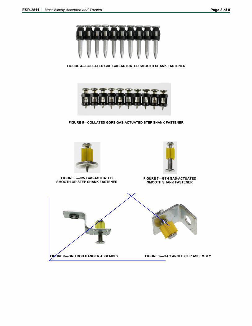
ESR-2811 | Most Widely Accepted and Trusted Page 8 of 8
FIGURE 4—COLLATED GDP GAS-ACTUATED SMOOTH SHANK FASTENER
FIGURE 5—COLLATED GDPS GAS-ACTUATED STEP SHANK FASTENER
FIGURE 3—FASTENER PENETRATION THROUGH STEEL WHERE REQUIRED
FIGURE 7—GTH GAS-ACTUATED SMOOTH SHANK FASTENER
FIGURE 6—GW GAS-ACTUATED SMOOTH OR STEP SHANK FASTENER
FIGURE 8—GRH ROD HANGER ASSEMBLY FIGURE 9—GAC ANGLE CLIP ASSEMBLY
299183
Rectangle
299183
Line
299183
Line
299183
Typewritten Text
*
299183
Typewritten Text
*
299183
Typewritten Text
Deleted by the City of Los Angeles
299183
Typewritten Text
299183
Typewritten Text
*
Gas Concrete Nailer Fuel Cell
SAFETY DATA SHEET
Gas Fuel Cell Page 1 of 7 SDS North America
1. IDENTIFICATION
Product Identifier: GFC34 and GCF34-RC2 Recommended Use: Gas Concrete Nailer Fuel Cell
Use Restrictions: None Known.
Company: Simpson Strong-Tie Company Inc.
Address: 5956 W. Las Positas Blvd.
Pleasanton, CA 94588, USA
Phone: 1-800-999-5099
Website: www.strongtie.com
Emergency: 1-800-535-5053 (US/Canada)
1-352-323-3500 (International)
For most current SDS, please visit our website at www.strongtie.com/sds
2. HAZARD IDENTIFICATION
Physical Hazards: Flammables Gases Category 1
Gases Under Pressure Liquefied Gas
Health Hazards: Not Classified.
Environmental Hazards: Not Classified.
Signal Word: DANGER!
Hazard Statements: Extremely flammable gas. Contains gas under pressure; may explode if heated.
Precautionary Statements:
Prevention: Keep away from heat/sparks/open flame/hot surfaces. No smoking. Do not breathe
fumes/vapors.
Response: Leaking gas fire: Do not extinguish, unless leak can be stopped safely. Eliminate all
ignition sources if safe to do so.
Storage: Store locked up. Store in a well-ventilated place. Protect from sunlight.
Disposal: Dispose of contents/container in accordance with local/regional/national regulations.
Hazards not otherwise Simple Asphyxiant: Product may displace oxygen content in the air causing
Classified (HNOC): asphyxiation if released in a confined area. High concentrations may have an anesthetic
effect.
Direct contact may cause frostbite (“cold” burn).
3. COMPOSITION INFORMATION
Chemical Name CAS Number Weight %
Propane 74-98-6 0-99
Isobutane 75-28-5 1-60
Propylene 115-07-1 0-60
n-Butane 106-97-8 1-43
Composition Note: This product is a mixture. Hazardous ingredients are listed above. May include other nonhazardous
ingredients. May include other trace ingredients, see Section 15.
4. FIRST-AID MEASURES
Eye Contact: Immediately flush eyes with plenty of lukewarm water for at least 15 minutes while
holding the eyes open. Remove contact lenses if present and easy to do. If redness,
burning, blurred vision, or swelling persists, consult a physician.
Skin Contact: Treat burned or frostbitten skin by washing or immersing the affected area in lukewarm
water. If rash or irritation persists consult a physician.
Ingestion: This material is a gas under normal atmospheric conditions. Ingestion is unlikely.
Gas Concrete Nailer Fuel Cell
SAFETY DATA SHEET
Gas Fuel Cell Page 2 of 7 SDS North America
Inhalation: Remove patient to fresh air. Give oxygen or artificial respiration if needed. If patient
continues to experience difficulty breathing, consult a physician.
Most Important Symptoms: Irritant effects.
General Information: Provide general supportive measures and treat symptomatically. Symptoms may be
delayed. Ensure that medical personnel are aware of the material(s) involved, and take
precautions to protect themselves. If exposed or concerned: Get medical advice/attention.
Wash contaminated clothing before reuse.
5. FIRE-FIGHTING MEASURES
Suitable Extinguishing Media: Dry chemical or carbon dioxide is recommended. Carbon dioxide can displace oxygen.
Additional Information: Use caution when applying carbon dioxide in a confined space.
Hazards during Fire-Fighting: This material is extremely flammable and can be ignited by heat, spark, flames, or other
sources of ignition (e.g., static electricity, pilot lights, or mechanical/electrical equipment,
and electronic devices such as cell phones, computers, calculators, and pagers which have
not been certified as intrinsically safe). Vapors may travel considerable distances to a
source of ignition where they can ignite, flash back, or explode. May create vapor/air
explosion hazard indoors, in confined spaces, outdoors, or in sewers. If container is not
properly cooled, it can rupture in the heat of a fire. Closed containers exposed to extreme
heat can rupture due to pressure buildup.
Fire-Fighting Procedures: Use standard fire-fighting procedures and consider the hazards of other involved
materials. In case of fire and/or explosion do not breathe fumes. Self-contained breathing
apparatus and full protective clothing must be worn. Isolate fuel supply from fire. Move
undamaged containers from immediate hazard area if it can be done with minimal risk.
Stay away from ends of container. Stop spill/release if it can be done with minimal risk.
If this cannot be done, allow fire to burn. Cool equipment exposed to fire with water, if it
can be done with minimal risk. Water spray may be useful in minimizing or dispersing
vapors and to protect personnel. Prevent runoff from fire control or dilution from entering
streams, sewers, or drinking water supply.
6. ACCIDENTAL RELEASE MEASURES
Personal Precautions: Keep unnecessary personnel away. Eliminate all ignition sources (no smoking, flares,
sparks, or flames in immediate area). Wear appropriate personal protective equipment.
Do not touch damaged containers or spilled material unless wearing appropriate
protective clothing. Avoid inhalation of vapors or mists. Ensure adequate ventilation.
Local authorities should be advised if significant spillages cannot be contained.
Clean-up Methods: Keep all sources of ignition and hot metal surfaces away from spill/release. The use of
explosion-proof electrical equipment is recommended. Stay upwind and away from
spill/release. Notify person downwind of the spill/release. Isolate danger area and keep
unauthorized personnel out. Stop spill/release if it can be done with minimal risk. Water
spray may be useful in minimizing or dispersing vapors.
Environmental Precautions: Avoid release to the environment. Contact local authorities in case of spillage to
drain/aquatic environment. Prevent further leakage or spillage if safe to do so.
7. HANDLING AND STORAGE
Handling: In addition to limitations on storage temperature, fuel cells should be handled and stored
so as to avoid puncture. Even when the fuel cell is empty, the can still contains
flammable gas. Do not puncture fuel cell or expose fuel cell to high temperature. Do not
attempt to refill the fuel cell. The use of explosion-proof electrical equipment is
recommended and may be required. Keep away from open flames, hot surfaces and
sources of ignition. When using, do not eat, drink or smoke. Avoid contact with eyes,
skin, and clothing. Wash thoroughly after handling. Observe good industrial hygiene
practices.
Storage: Store locked up. Pressurized container: must not be exposed to temperatures above 50°C
(120°F). Ground all equipment containing material. Store in a cool, dry place out of
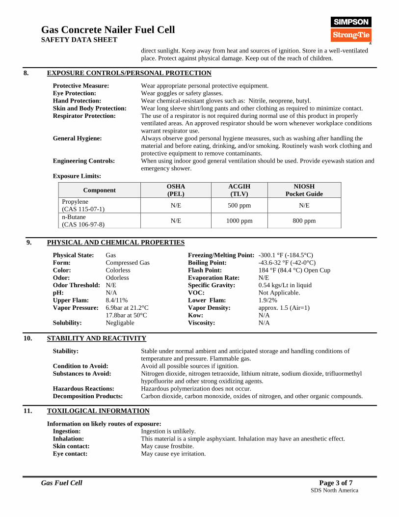
Gas Concrete Nailer Fuel Cell
SAFETY DATA SHEET
Gas Fuel Cell Page 3 of 7 SDS North America
direct sunlight. Keep away from heat and sources of ignition. Store in a well-ventilated
place. Protect against physical damage. Keep out of the reach of children.
8. EXPOSURE CONTROLS/PERSONAL PROTECTION
Protective Measure: Wear appropriate personal protective equipment.
Eye Protection: Wear goggles or safety glasses.
Hand Protection: Wear chemical-resistant gloves such as: Nitrile, neoprene, butyl.
Skin and Body Protection: Wear long sleeve shirt/long pants and other clothing as required to minimize contact.
Respirator Protection: The use of a respirator is not required during normal use of this product in properly
ventilated areas. An approved respirator should be worn whenever workplace conditions
warrant respirator use.
General Hygiene: Always observe good personal hygiene measures, such as washing after handling the
material and before eating, drinking, and/or smoking. Routinely wash work clothing and
protective equipment to remove contaminants.
Engineering Controls: When using indoor good general ventilation should be used. Provide eyewash station and
emergency shower.
After Cur Exposure Limits:
9. PHYSICAL AND CHEMICAL PROPERTIES
Physical State: Gas Freezing/Melting Point: -300.1 °F (-184.5°C)
Form: Compressed Gas Boiling Point: -43.6-32 °F (-42-0°C)
Color: Colorless Flash Point: 184 °F (84.4 °C) Open Cup
Odor: Odorless Evaporation Rate: N/E
Odor Threshold: N/E Specific Gravity: 0.54 kgs/Lt in liquid
pH: N/A VOC: Not Applicable.
Upper Flam: 8.4/11% Lower Flam: 1.9/2%
Vapor Pressure: 6.9bar at 21.2°C Vapor Density: approx. 1.5 (Air=1)
17.8bar at 50°C Kow: N/A
Solubility: Negligable Viscosity: N/A
10. STABILITY AND REACTIVITY
Stability: Stable under normal ambient and anticipated storage and handling conditions of
temperature and pressure. Flammable gas.
Condition to Avoid: Avoid all possible sources if ignition.
Substances to Avoid: Nitrogen dioxide, nitrogen tetraoxide, lithium nitrate, sodium dioxide, trifluormethyl
hypofluorite and other strong oxidizing agents.
Hazardous Reactions: Hazardous polymerization does not occur.
Decomposition Products: Carbon dioxide, carbon monoxide, oxides of nitrogen, and other organic compounds.
11. TOXILOGICAL INFORMATION
Information on likely routes of exposure:
Ingestion: Ingestion is unlikely.
Inhalation: This material is a simple asphyxiant. Inhalation may have an anesthetic effect.
Skin contact: May cause frostbite.
Eye contact: May cause eye irritation.
Component OSHA
(PEL)
ACGIH
(TLV)
NIOSH
Pocket Guide
Propylene
(CAS 115-07-1) N/E 500 ppm N/E
n-Butane
(CAS 106-97-8) N/E 1000 ppm 800 ppm

Gas Concrete Nailer Fuel Cell
SAFETY DATA SHEET
Gas Fuel Cell Page 4 of 7 SDS North America
Information on toxicological effect:
Acute toxicity: Not expected to be acutely toxic.
Component Species Test Result
Propane (CAS 74-98-6)
Acute, Inhalation, LC50 Rat >1442 mg/l, 15 minutes
Propylene (CAS 74-98-6)
Acute, Inhalation, LC50 Rat 658 mg/l, 4 Hours
n-Butane (CAS 106-97-8)
Acute, Inhalation, LC50 Rat 658 mg/l, 4 Hours
Skin corrosion/irritation: May cause frostbite with potential for tissue damage.
Eye damage/eye irritation: May cause eye irritation.
Respiratory sensitization: Not classified.
Skin sensitization: Not classified.
Germ cell mutagenicity: Not classified.
Carcinogenicity: Not classified.
IARC Monographs. Overall Evaluation of Carcinogenicity
Propylene (CAS 115-07-1) 3 Not Classifiable as to carcinogenicity in humans.
Reproductive toxicity: Not classified.
Aspiration hazard: Not Applicable.
Specific target organ toxicity:
Single exposure Not classified.
Repeated exposure Not classified.
Further information: Toxicological, ecotoxicological, physical, and chemical properties may not have been
fully investigated. Hazard data above is estimated based on best available information.
Some workers with certain pre-existing medical conditions such as: asthma, allergies,
or impaired pulmonary and/or liver functions, or who may be particularly susceptible
to this material, may be affected by exposure to this material.
12. ECOLOGICAL INFORMATION
Ecotoxicity: There is no information available on the ecotoxicological effects of petroleum gases.
Because of their high volatility, they are unlikely to cause ground or water pollution.
Petroleum gases released into the environment will rapidly disperse into the
atmosphere and undergo photochemical degradation.
Persistence and degradability: The product is readily biodegradable.
Bioaccumulative potential: Not expected to bioaccumulate.
Mobility in soil: May evaporate quickly.
Other adverse effects: No other adverse environmental effects (e.g. ozone depletion, photochemical ozone
creation potential, endocrine disruption, global warming potential) are expected from
this product.
13. DISPOSAL CONSIDERATIONS
Waste Disposal of Substance: Do not crush, puncture, or incinerate spent containers. Large numbers of aerosol
containers may require handling as a hazardous waste. Dispose of container and unused
contents in accordance with federal, state, and local requirements.
* Even when used up the fuel cell still contains flammable gas. Do not puncture the can or incinerate.
14. TRANSPORTATION INFORMATION
United States Department of Transportation (USDOT): Consumer Commodity, ORM-D / Limited Quantity
International Air Transportation Association (IATA):
UN number: UN1950
UN proper shipping name: Aerosols, Flammable
Transport hazard class(es): 2.1

Gas Concrete Nailer Fuel Cell
SAFETY DATA SHEET
Gas Fuel Cell Page 5 of 7 SDS North America
Special precautions for user: Read safety instructions, SDS and emergency procedures before handling.
Transport in bulk according to Annex II of MARPOL 73/78 and the IBC Code: This substance/mixture is not intended to be transported in bulk.
This information does not cover all specific regulatory or operational requirements of this product. The classifications for
transportation may vary by container volume or different regional or national regulations.
15. REGULATORY INFORMATION
US Federal Regulations This product is a "Hazardous Chemical" as defined by the OSHA Hazard
Communication Standard, 29 CFR 1910.1200.
TSCA Section 12(b) Export Notification (40 CFR 707, Subpt. D) Not regulated.
US. OSHA Specifically Regulated Substances (29 CFR 1910.1001-1050) Not listed.
CERCLA Hazardous Substance List (40 CFR 302.4) Propane (CAS 74-97-8) LISTED
Propylene (CAS 115-07-1) LISTED
n-Butane (CAS 106-97-8) LISTED
Superfund Amendments and Reauthorization Act of 1986 (SARA)
Hazard categories Immediate Hazard Yes
Delayed Hazard Yes
Fire Hazard Yes
Pressure Hazard Yes
Reactivity Hazard Yes
SARA 302 Extremely hazardous substance No
SARA 311/312 Hazardous chemical Yes
SARA 313 (TRI reporting)
Component CAS % In Blend (approx.)
Propylene 115-07-1 0-60
Other Federal Regulations
Clean Air Act (CAA) Section 112(r) Accidental Release Prevention (40 CFR 68.130)
Propane (CAS 74-97-8) LISTED
Propylene (CAS 115-07-1) LISTED
n-Butane (CAS 106-97-8) LISTED
US State Right-To-Know Lists
Chemical Massachusetts
RTK
New Jersey Work
and Community
RTK Act
Pennsylvania Worker
and Community
RTK Law
Rhode
Island RTK
Butane
(CAS 106-97-8) Listed Listed Listed Listed
Propane
(CAS 74-98-6) Listed Listed Listed Listed
Propylene
(CAS 115-07-1) Listed Listed Listed Listed
This product does not contain known levels of any chemicals known to the State of California to cause cancer or reproductive
harm as per California Proposition 65 (Safe Drinking Water and Toxic Enforcement Act of 1986).
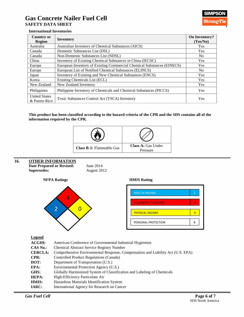
Gas Concrete Nailer Fuel Cell
SAFETY DATA SHEET
Gas Fuel Cell Page 6 of 7 SDS North America
International Inventories
This product has been classified according to the hazard criteria of the CPR and the SDS contains all of the
information required by the CPR.
Class B-1: Flammable Gas Class A: Gas Under
Pressure
16. OTHER INFORMATION Date Prepared or Revised: June 2014 Supersedes: August 2012
NFPA Ratings HMIS Rating
Legend
ACGIH: American Conference of Governmental Industrial Hygienists
CAS No.: Chemical Abstract Service Registry Number
CERCLA: Comprehensive Environmental Response, Compensation and Liability Act (U.S. EPA)
CPR: Controlled Product Regulations (Canada)
DOT: Department of Transportation (U.S.)
EPA: Environmental Protection Agency (U.S.)
GHS: Globally Harmonized System of Classification and Labeling of Chemicals
HEPA: High-Efficiency Particulate Air
HMIS: Hazardous Materials Identification System
IARC: International Agency for Research on Cancer
Country or
Region Inventory
On Inventory?
(Yes/No)
Australia Australian Inventory of Chemical Substances (AICS) Yes
Canada Domestic Substances List (DSL) Yes
Canada Non-Domestic Substances List (NDSL) No
China Inventory of Existing Chemical Substances in China (IECSC) Yes
Europe European Inventory of Existing Commercial Chemical Substances (EINECS) Yes
Europe European List of Notified Chemical Substances (ELINCS) No
Japan Inventory of Existing and New Chemical Substances (ENCS) Yes
Korea Existing Chemicals List (ECL) Yes
New Zealand New Zealand Inventory Yes
Philippines Philippine Inventory of Chemicals and Chemical Substances (PICCS) Yes
United States
& Puerto Rico Toxic Substances Control Act (TSCA) Inventory Yes
HEALTH HAZARD
FLAMMABILTY HAZARD
PHYSICAL HAZARD
2
4
0
PERSONAL PROTECTION B
4
2 0
Gas Concrete Nailer Fuel Cell
SAFETY DATA SHEET
Gas Fuel Cell Page 7 of 7 SDS North America
IATA: International Air Transport Association
IMDG: International Maritime Dangerous Goods code
LPP: Limité Permisible Ponderado (Chile)
NIOSH: National Institute of Occupational Safety and Health (U.S.)
NFPA: National Fire Protection Association (US)
NTP: National Toxicology Program (US)
OSHA: Occupational Safety and Health Administration (U.S.)
PEL: Permissible Exposure Limit
SARA: Superfund Amendments and Reauthorization Act (U.S. EPA)
SDS: Safety Data Sheet
STEL: Short Term Exposure Limit (15 minute Time Weighted Average)
STOT: Specific Target Organ Toxicity (GHS Classification)
TLV: Threshold Limit Value
TSCA: Toxic Substances Control Act (U.S.)
TWA: Time Weighted Average (exposure for 8-hour workday)
U.S.: United States
VOC: Volatile Organic Compounds
WHMIS: Canadian Workplace Hazardous Materials Information System
Safety Data Sheet (SDS) is prepared by Simpson Strong-Tie Co. in compliance with the requirements of OSHA 29
CFR Part 1910.1200. The information it contains is offered in good faith as accurate as of the date of this SDS. This
SDS is provided solely for the purpose of conveying health, safety, and environmental information. No warranty,
expressed or implied, is given. Health and Safety precautions may not be adequate for all individuals and/or
situations. It is the user's obligation to evaluate and use this product safely and to comply with all applicable laws
and regulations.
© 2014 Simpson Strong-Tie Company Inc.
FOR INTERNAL USE ONLY
A Component 764:
XCGAS
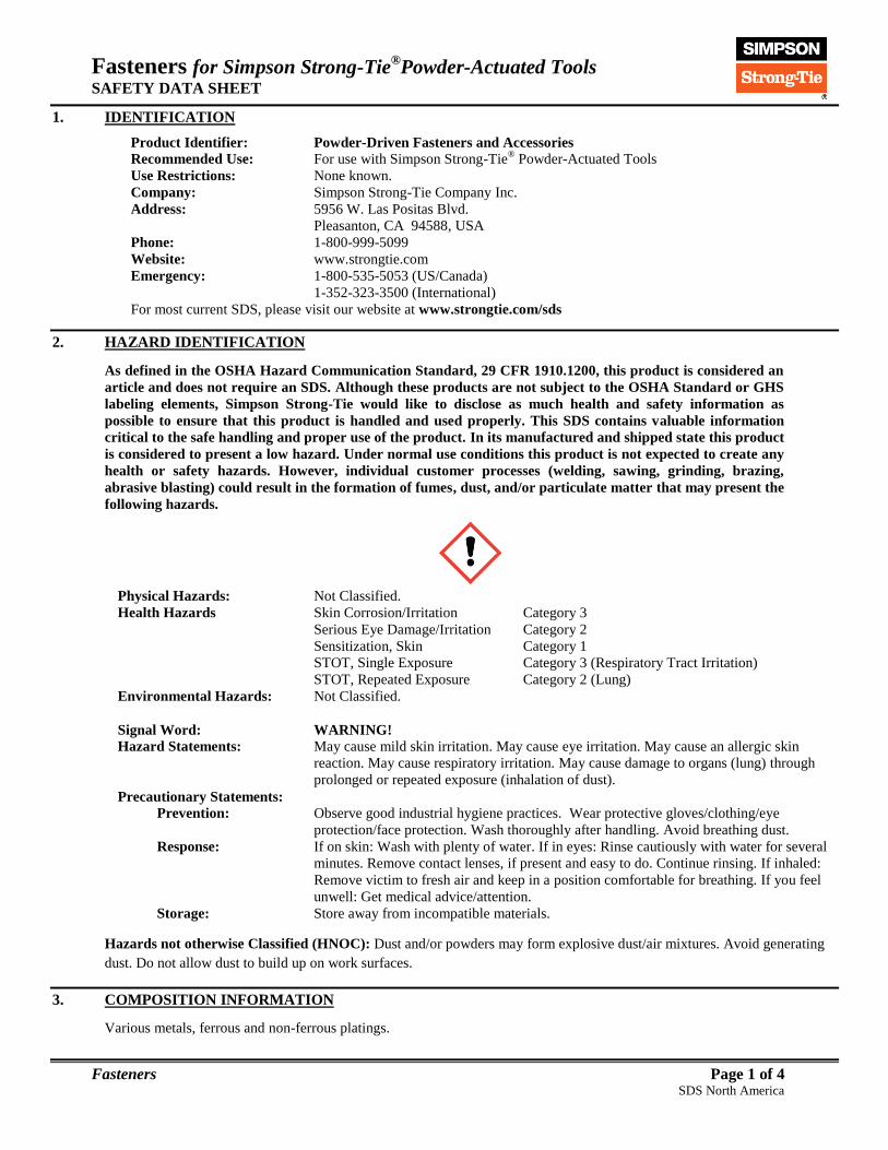
Fasteners for Simpson Strong-Tie®Powder-Actuated Tools
SAFETY DATA SHEET
Fasteners Page 1 of 4 SDS North America
1. IDENTIFICATION
Product Identifier: Powder-Driven Fasteners and Accessories Recommended Use: For use with Simpson Strong-Tie
® Powder-Actuated Tools
Use Restrictions: None known.
Company: Simpson Strong-Tie Company Inc.
Address: 5956 W. Las Positas Blvd.
Pleasanton, CA 94588, USA
Phone: 1-800-999-5099
Website: www.strongtie.com
Emergency: 1-800-535-5053 (US/Canada)
1-352-323-3500 (International)
For most current SDS, please visit our website at www.strongtie.com/sds
2. HAZARD IDENTIFICATION
As defined in the OSHA Hazard Communication Standard, 29 CFR 1910.1200, this product is considered an
article and does not require an SDS. Although these products are not subject to the OSHA Standard or GHS
labeling elements, Simpson Strong-Tie would like to disclose as much health and safety information as
possible to ensure that this product is handled and used properly. This SDS contains valuable information
critical to the safe handling and proper use of the product. In its manufactured and shipped state this product
is considered to present a low hazard. Under normal use conditions this product is not expected to create any
health or safety hazards. However, individual customer processes (welding, sawing, grinding, brazing,
abrasive blasting) could result in the formation of fumes, dust, and/or particulate matter that may present the
following hazards.
Physical Hazards: Not Classified.
Health Hazards Skin Corrosion/Irritation Category 3
Serious Eye Damage/Irritation Category 2
Sensitization, Skin Category 1
STOT, Single Exposure Category 3 (Respiratory Tract Irritation)
STOT, Repeated Exposure Category 2 (Lung)
Environmental Hazards: Not Classified.
Signal Word: WARNING!
Hazard Statements: May cause mild skin irritation. May cause eye irritation. May cause an allergic skin
reaction. May cause respiratory irritation. May cause damage to organs (lung) through
prolonged or repeated exposure (inhalation of dust).
Precautionary Statements:
Prevention: Observe good industrial hygiene practices. Wear protective gloves/clothing/eye
protection/face protection. Wash thoroughly after handling. Avoid breathing dust.
Response: If on skin: Wash with plenty of water. If in eyes: Rinse cautiously with water for several
minutes. Remove contact lenses, if present and easy to do. Continue rinsing. If inhaled:
Remove victim to fresh air and keep in a position comfortable for breathing. If you feel
unwell: Get medical advice/attention.
Storage: Store away from incompatible materials.
Hazards not otherwise Classified (HNOC): Dust and/or powders may form explosive dust/air mixtures. Avoid generating
dust. Do not allow dust to build up on work surfaces.
3. COMPOSITION INFORMATION
Various metals, ferrous and non-ferrous platings.

Fasteners for Simpson Strong-Tie®Powder-Actuated Tools
SAFETY DATA SHEET
Fasteners Page 2 of 4 SDS North America
4. FIRST-AID MEASURES
Eye Contact: Flush with large amounts of water to remove particles. If redness, burning, blurred vision,
or swelling persists, consult a physician.
Skin Contact: Wash affected area with soap and water. If a thermal burn has occurred, flush area with
cold water and consult a physician.
Ingestion: Not a probable route of industrial exposure, however, if ingested immediately consult a
physician. Inhalation: For over-exposure to airborne dust or fumes, move patient to fresh air. Give oxygen or
artificial respiration if needed. If patient continues to experience difficulty breathing,
consult a physician. Most Important Symptoms: Irritant effects.
General Information: Provide general supportive measures and treat symptomatically. Ensure that medical
personnel are aware of the material(s) involved, and take precautions to protect
themselves. If exposed or concerned: Get medical advice/attention.
5. FIRE-FIGHTING MEASURES
Suitable Extinguishing Media: This material is not combustible and will not burn. Choose extinguishing media suitable
for surrounding materials.
Additional Information: None known. Hazards during Fire-Fighting: Dusts may present a fire or explosion hazard under rare favoring conditions of particle
size, dispersion and strong ignition source. However, this is not expected to be a problem
under normal handling conditions.
Fire-Fighting Procedures: Use standard fire-fighting procedures and consider the hazards of other involved
materials. In case of fire and/or explosion do not breathe fumes. Self-contained breathing
apparatus and full protective clothing must be worn. Prevent runoff from fire control or
dilution from entering streams, sewers, or drinking water supply.
6. ACCIDENTAL RELEASE MEASURES
Personal Precautions: Wear appropriate personal protective equipment. Avoid inhalation of dusts.
Clean-up Methods: Solid articles do not represent a spill hazard. Avoid actions that cause dust to be
generated. Collect dust generated during processing using a vacuum cleaner equipped
with a HEPA filter. If not possible, gently moisten dust before collection with shovel,
broom, or the like.
Environmental Precautions: Avoid release of dust to the environment. Avoid discharge into drains, water courses or
onto the ground.
7. HANDLING AND STORAGE
Handling: Wear appropriate personal protective equipment. If grinding or cutting use work methods
which minimize dust production. Avoid inhalation of dust. Ensure adequate ventilation.
Wash thoroughly after handling. Observe good industrial hygiene practices.
Storage: Store away from incompatible materials.
8. EXPOSURE CONTROLS/PERSONAL PROTECTION
Protective Measure: Protective coatings are used on most metal fasteners. Typically this will be commercial
zinc, zinc plating with chromate conversion coating, hot dipped galvanizing, ceramic
plating, or mechanically galvanized plating. This information should be considered when
evaluating employee personal protective equipment.
Eye Protection: Wear goggles or safety glasses to protect eyes from dust and other particles.
Hand Protection: Gloves recommended.
Skin and Body Protection: Wear long sleeve shirts/long pants and other clothing as required to minimize contact.
Respirator Protection: Not required in properly ventilated areas. General Hygiene: Always observe good personal hygiene measures, such as washing after handling the
material and before eating, drinking, and/or smoking. Routinely wash work clothing and
protective equipment to remove contaminants.
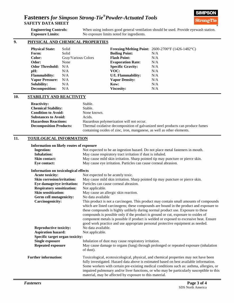
Fasteners for Simpson Strong-Tie®Powder-Actuated Tools
SAFETY DATA SHEET
Fasteners Page 3 of 4 SDS North America
Engineering Controls: When using indoors good general ventilation should be used. Provide eyewash station.
Exposure Limits: No exposure limits noted for ingredients.
9. PHYSICAL AND CHEMICAL PROPERTIES
Physical State: Solid Freezing/Melting Point: 2600-2700°F (1426-1482°C)
Form: Solid Boiling Point: N/A
Color: Gray/Various Colors Flash Point: N/A
Odor: None Evaporation Rate: N/A
Odor Threshold: N/A Specific Gravity: N/A
pH: N/A VOC: N/A
Flammability: N/A U/L Flammability: N/A
Vapor Pressure: N/A Vapor Density: N/A
Solubility: N/A Kow: N/A
Decomposition: N/A Viscosity: N/A
10. STABILITY AND REACTIVITY
Reactivity: Stable.
Chemical Stability: Stable.
Condition to Avoid: None known. Substances to Avoid: Acids.
Hazardous Reactions: Hazardous polymerization will not occur.
Decomposition Products: Thermal oxidative decomposition of galvanized steel products can produce fumes
containing oxides of zinc, iron, manganese, as well as other elements.
11. TOXILOGICAL INFORMATION
Information on likely routes of exposure
Ingestion: Not expected to be an ingestion hazard. Do not place metal fasteners in mouth.
Inhalation: May cause respiratory tract irritation if dust is inhaled.
Skin contact: May cause mild skin irritation. Sharp pointed tip may puncture or pierce skin.
Eye contact: May cause eye irritation. Particles can cause corneal abrasion.
Information on toxicological effects
Acute toxicity: Not expected to be acutely toxic.
Skin corrosion/irritation: May cause mild skin irritation. Sharp pointed tip may puncture or pierce skin.
Eye damage/eye irritation: Particles can cause corneal abrasion.
Respiratory sensitization: Not applicable.
Skin sensitization: May cause an allergic skin reaction.
Germ cell mutagenicity: No data available
Carcinogenicity: This product is not a carcinogen. This product may contain small amounts of compounds
which are listed carcinogens; these compounds are bound in the product and exposure to
these compounds is highly unlikely during normal product use. Exposure to these
compounds is possible only if the product is ground or cut, exposure to oxides of
component metals is possible if product is welded or exposed to excessive heat. Ensure
good work practice and use appropriate personal protective equipment as needed.
Reproductive toxicity: No data available.
Aspiration hazard: Not applicable.
Specific target organ toxicity:
Single exposure Inhalation of dust may cause respiratory irritation.
Repeated exposure May cause damage to organs (lung) through prolonged or repeated exposure (inhalation
of dust).
Further information: Toxicological, ecotoxicological, physical, and chemical properties may not have been
fully investigated. Hazard data above is estimated based on best available information.
Some workers with certain pre-existing medical conditions such as: asthma, allergies, or
impaired pulmonary and/or liver functions, or who may be particularly susceptible to this
material, may be affected by exposure to this material.
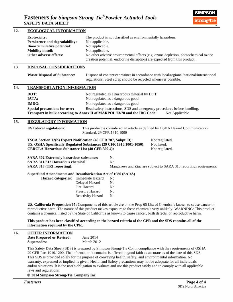
Fasteners for Simpson Strong-Tie®Powder-Actuated Tools
SAFETY DATA SHEET
Fasteners Page 4 of 4 SDS North America
12. ECOLOGICAL INFORMATION
Ecotoxicity: The product is not classified as environmentally hazardous.
Persistence and degradability: Not applicable.
Bioaccumulative potential: Not applicable.
Mobility in soil: Not applicable.
Other adverse effects: No other adverse environmental effects (e.g. ozone depletion, photochemical ozone
creation potential, endocrine disruption) are expected from this product.
13. DISPOSAL CONSIDERATIONS
Waste Disposal of Substance: Dispose of contents/container in accordance with local/regional/national/international
regulations. Steel scrap should be recycled whenever possible.
14. TRANSPORTATION INFORMATION
DOT: Not regulated as a hazardous material by DOT.
IATA: Not regulated as a dangerous good.
IMDG: Not regulated as a dangerous good.
Special precautions for user: Read safety instructions, SDS and emergency procedures before handling.
Transport in bulk according to Annex II of MARPOL 73/78 and the IBC Code: Not Applicable
15. REGULATORY INFORMATION
US federal regulations: This product is considered an article as defined by OSHA Hazard Communication
Standard, 29 CFR 1910.1000
TSCA Section 12(b) Export Notification (40 CFR 707, Subpt. D): Not regulated.
US. OSHA Specifically Regulated Substances (29 CFR 1910.1001-1050): Not listed.
CERCLA Hazardous Substance List (40 CFR 302.4): Not regulated.
SARA 302 Extremely hazardous substance: No
SARA 311/312 Hazardous chemical: No
SARA 313 (TRI reporting): Manganese and Zinc are subject to SARA 313 reporting requirements.
Superfund Amendments and Reauthorization Act of 1986 (SARA)
Hazard categories: Immediate Hazard No
Delayed Hazard No
Fire Hazard No
Pressure Hazard No
Reactivity Hazard No
US. California Proposition 65: Components of this article are on the Prop 65 List of Chemicals known to cause cancer or
reproductive harm. The nature of this product makes exposure to these chemicals very unlikely. WARNING: This product
contains a chemical listed by the State of California as known to cause cancer, birth defects, or reproductive harm.
This product has been classified according to the hazard criteria of the CPR and the SDS contains all of the
information required by the CPR.
16. OTHER INFORMATION Date Prepared or Revised: June 2014
Supersedes: March 2012
This Safety Data Sheet (SDS) is prepared by Simpson Strong-Tie Co. in compliance with the requirements of OSHA
29 CFR Part 1910.1200. The information it contains is offered in good faith as accurate as of the date of this SDS.
This SDS is provided solely for the purpose of conveying health, safety, and environmental information. No
warranty, expressed or implied, is given. Health and Safety precautions may not be adequate for all individuals
and/or situations. It is the user's obligation to evaluate and use this product safely and to comply with all applicable
laws and regulations.
2014 Simpson Strong-Tie Company Inc.

Tool Cleaner
SAFETY DATA SHEET
Tool Cleaner Page 1 of 7 SDS North America
1. IDENTIFICATION
Product Identifier: Cleaner (GCN-CL04) Recommended Use: Tool Cleaner for use with Simpson Strong-Tie® Gas Concrete Nailer
Use Restrictions: None Known.
Company: Simpson Strong-Tie Company Inc.
Address: 5956 W. Las Positas Blvd.
Pleasanton, CA 94588 USA
Phone: 1-800-999-5099
Website: www.strongtie.com
Emergency: 1-800-535-5053 (US/Canada)
1-352-323-3500 (International)
For most current SDS, please visit our website at www.strongtie.com/sds
2. HAZARD IDENTIFICATION
Physical Hazards: Flammable Liquids Category 4
Health Hazard: Serious Eye Irritation/Damage Category 2B
Sensitization, Skin Category 1
Aspiration Hazard Category 2
STOT, Single Exposure Category 3 (Narcotic Effects)
Environmental Hazards: Not Classified.
Signal Word: WARNING!
Hazard Statements: Combustible liquid. Causes eye irritation. May cause an allergic skin reaction. May be
harmful if swallowed and enters the lungs. May cause drowsiness or dizziness.
Precautionary Statements:
Prevention: Obtain special instructions before use. Do not handle until all safety precautions have
been read and understood. Keep away from heat/sparks/open flames/hot surfaces. - No
smoking. Wear protective gloves/protective clothing/eye protection/face protection.
Avoid breathing mist or vapor. Wash thoroughly after handling.
Response: In case of fire: Use foam, carbon dioxide, dry powder or water fog for extinction. If
inhaled: Remove victim to fresh air and keep in a rest position comfortable for breathing.
If experiencing respiratory symptoms: Call poison center/doctor. If swallowed: Do NOT
induce vomiting. If on skin: Wash with plenty of water. If skin irritation or rash occurs:
Get medical advice/attention. Take off contaminated clothing and wash before re-use. If
in eyes: Rinse cautiously with water for several minutes. Remove contact lenses, if
present and easy to do. Continue rinsing. If eye irritation persists: Get medical
advice/attention.
Storage: Store in a well-ventilated place. Keep container tightly closed. Keep cool.
Disposal: Dispose of contents/container in accordance with local/regional/national regulations.
Hazards not otherwise Classified (HNOC): None known.
3. COMPOSITION INFORMATION
Chemical Name CAS Number Weight %
Distillates (petroleum), heavy aliphatic 64742-96-7 > 80
2-Butoxyethanol 111-76-2 < 5
Composition Note: This product is a mixture. Hazardous ingredients are listed above. May include other nonhazardous
ingredients. May include other trace ingredients, see Section 15.
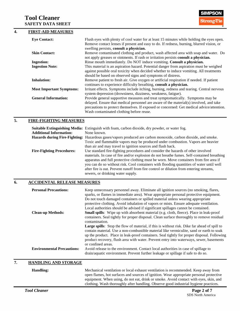
Tool Cleaner
SAFETY DATA SHEET
Tool Cleaner Page 2 of 7 SDS North America
4. FIRST-AID MEASURES
Eye Contact: Flush eyes with plenty of cool water for at least 15 minutes while holding the eyes open.
Remove contact lenses if present and easy to do. If redness, burning, blurred vision, or
swelling persists, consult a physician.
Skin Contact: Remove contaminated clothing and product, wash affected area with soap and water. Do
not apply greases or ointments. If rash or irritation persists consult a physician.
Ingestion: Rinse mouth immediately. Do NOT induce vomiting. Consult a physician.
Ingestion Note: This material is an aspiration hazard. Potential danger from aspiration must be weighed
against possible oral toxicity when decided whether to induce vomiting. All treatments
should be based on observed signs and symptoms of distress.
Inhalation: Remove patient to fresh air. Give oxygen or artificial respiration if needed. If patient
continues to experience difficulty breathing, consult a physician.
Most Important Symptoms: Irritant effects. Symptoms include itching, burning, redness and tearing. Central nervous
system depression (drowsiness, dizziness, weakness, fatigue).
General Information: Provide general supportive measures and treat symptomatically. Symptoms may be
delayed. Ensure that medical personnel are aware of the material(s) involved, and take
precautions to protect themselves. If exposed or concerned: Get medical advice/attention.
Wash contaminated clothing before reuse.
5. FIRE-FIGHTING MEASURES
Suitable Extinguishing Media: Extinguish with foam, carbon dioxide, dry powder, or water fog.
Additional Information: None known.
Hazards during Fire-Fighting: Hazardous gases/vapors produced are carbon monoxide, carbon dioxide, and smoke.
Toxic and flammable vapors may be produced under combustion. Vapors are heavier
than air and may travel to ignition sources and flash back.
Fire-Fighting Procedures: Use standard fire-fighting procedures and consider the hazards of other involved
materials. In case of fire and/or explosion do not breathe fumes. Self-contained breathing
apparatus and full protective clothing must be worn. Move containers from fire area if
you can do so without risk. Cool containers with flooding quantities of water until well
after fire is out. Prevent runoff from fire control or dilution from entering streams,
sewers, or drinking water supply.
6. ACCIDENTAL RELEASE MEASURES
Personal Precautions: Keep unnecessary personnel away. Eliminate all ignition sources (no smoking, flares,
sparks, or flames in immediate area). Wear appropriate personal protective equipment.
Do not touch damaged containers or spilled material unless wearing appropriate
protective clothing. Avoid inhalation of vapors or mists. Ensure adequate ventilation.
Local authorities should be advised if significant spillages cannot be contained.
Clean-up Methods: Small spills: Wipe up with absorbent material (e.g. cloth, fleece). Place in leak-proof
containers. Seal tightly for proper disposal. Clean surface thoroughly to remove residual
contamination.
Large spills: Stop the flow of material, if this is without risk. Dike far ahead of spill to
contain material. Use a non-combustible material like vermiculite, sand or earth to soak
up the product. Place in leak-proof containers. Seal tightly for proper disposal. Following
product recovery, flush area with water. Prevent entry into waterways, sewer, basements
or confined areas.
Environmental Precautions: Avoid release to the environment. Contact local authorities in case of spillage to
drain/aquatic environment. Prevent further leakage or spillage if safe to do so.
7. HANDLING AND STORAGE
Handling: Mechanical ventilation or local exhaust ventilation is recommended. Keep away from
open flames, hot surfaces and sources of ignition. Wear appropriate personal protective
equipment. When using, do not eat, drink or smoke. Avoid contact with eyes, skin, and
clothing. Wash thoroughly after handling. Observe good industrial hygiene practices.

Tool Cleaner
SAFETY DATA SHEET
Tool Cleaner Page 3 of 7 SDS North America
Storage: Store away from incompatible materials(see section 10 of the SDS). Keep in original
container, keep container tightly closed. Store in a cool, dry place out of direct sunlight.
Keep away from heat and sources of ignition.
8. EXPOSURE CONTROLS/PERSONAL PROTECTION
Protective Measure: Wear appropriate personal protective equipment.
Eye Protection: Wear chemical splash goggles or safety glasses with side shield.
Hand Protection: Wear chemical-resistant gloves such as: Nitrile, neoprene, butyl.
Skin and Body Protection: Wear long sleeve shirt/long pants and other clothing as required to minimize contact.
Respirator Protection: Not required for properly ventilated areas. NIOSH or MSHA approved air-purifying
respirators should be used to control exposures when ventilation or other controls are
inadequate or discomfort or irritation is experienced.
General Hygiene: Always observe good personal hygiene measures, such as washing after handling the
material and before eating, drinking, and/or smoking. Routinely wash work clothing and
protective equipment to remove contaminants.
Engineering Controls: When using indoor good general ventilation should be used, use local exhaust or general
dilution ventilation to control exposure. Provide eyewash station.
After Cur Exposure Limits:
*Skin Designation: Material can be absorbed through the skin.
9. PHYSICAL AND CHEMICAL PROPERTIES
Physical State: Liquid Freezing/Melting Point: -105°F (-76°C)
Form: Thin Fluid Boiling Point: Approx. 188-288°F (370-550°C)
Color: Milky Flash Point: 178°F (81°C)
Odor: Low Odor Evaporation Rate: Slow
Odor Threshold: N/E Specific Gravity: 0.834 at 60°F (15.4°C)
pH: 7.2 VOC: N/E
Upper Flam: 7% Lower Flam: 0.6%
Vapor Pressure: < 1 mmHg at 77°F (25°C) Vapor Density: > 6 (Air=1)
Solubility: Soluble (100%) Kow: N/E
Decomposition: N/E Viscosity: N/E
10. STABILITY AND REACTIVITY
Reactivity: This product is stable and non-reactive under normal conditions.
Chemical Stability: Stable under normal storage conditions.
Condition to Avoid: High heat and open flame.
Substances to Avoid: Oxidizing agents, hypochlorites, chlorine.
Hazardous Reactions: Hazardous polymerization will not occur.
Decomposition Products: Carbon dioxide, carbon monoxide, oxides of nitrogen, and other organic compounds.
11. TOXILOGICAL INFORMATION
Information on likely routes of exposure:
Ingestion: Ingestion may cause irritation to the gastrointestinal tract. Aspiration hazard, do not
induce vomiting if product is swallowed. Consult a physician.
Inhalation: Vapors have a narcotic effect and may cause headache, fatigue, dizziness and nausea.
Skin contact: May cause skin irritation. May cause an allergic skin reaction.
Eye contact: Causes eye irritation.
Component OSHA
(PEL)
ACGIH
(TLV)
NIOSH
Pocket Guide
2-Butoxyethanol*
(CAS 111-76-2) 25 ppm (TWA) 20 ppm (TWA) 5 ppm

Tool Cleaner
SAFETY DATA SHEET
Tool Cleaner Page 4 of 7 SDS North America
Information on toxicological effect:
Acute toxicity: Occupational exposure may have a damaging effect.
Skin corrosion/irritation: May cause skin irritation.
Eye damage/eye irritation: Causes eye irritation.
Respiratory sensitization: No data available.
Skin sensitization: Repeated or prolonged exposure may cause sensitization by skin contact.
Germ cell mutagenicity: The available data does not indicate that any component present at greater than 0.1%
are mutagenic or genotoxic.
Carcinogenicity: This product is not considered to be a carcinogen by IARC, NTP, ACGIH, or OSHA.
Reproductive toxicity: This product is not expected to cause reproductive or developmental effects.
Aspiration hazard: May be harmful if swallowed and enters the lungs.
Specific target organ toxicity:
Single exposure May cause drowsiness or dizziness. May cause respiratory irritation.
Repeated exposure No data available.
Further information: Toxicological, ecotoxicological, physical, and chemical properties may not have been
fully investigated. Hazard data above is estimated based on best available information.
Some workers with certain pre-existing medical conditions such as: asthma, allergies,
or impaired pulmonary and/or liver functions, or who may be particularly susceptible
to this material, may be affected by exposure to this material.
12. ECOLOGICAL INFORMATION
Ecotoxicity: Information given is based on data on the components and the ecotoxicology of similar
products. The product is not classified environmentally hazardous. However, this does
not exclude the possibility that large or repeated spills can have a harmful or damaging
effect on the environment.
Persistence and degradability: Biodegradable.
Bioaccumulative potential: No data available.
Mobility in soil: No data available.
Other adverse effects: No other adverse environmental effects (e.g. ozone depletion, photochemical ozone
creation potential, endocrine disruption) are expected from this product.
13. DISPOSAL CONSIDERATIONS
Waste Disposal of Substance: Do not allow this material to drain into sewers/water supplies. Do not contaminate
ponds, waterways or ditches with chemical or used container. Dispose of
contents/container in accordance with local/regional/national/international regulations.
Container Disposal: Empty containers or liners may retain some product residues; follow label warnings
even after container is emptied. Empty containers should be taken to an approved waste
handling site for recycling or disposal.
14. TRANSPORTATION INFORMATION
United States Department of Transportation (USDOT): Not regulated for transport by DOT.
International Air Transportation Association (IATA): Not regulated as a hazardous material.
International Maritime Dangerous Goods Code (IMDG): Not regulated as a hazardous material.
Special precautions for user: Read safety instructions, SDS and emergency procedures before handling.
Transport in bulk according to Annex II of MARPOL 73/78 and the IBC Code: Not applicable.
This information does not cover all specific regulatory or operational requirements of this product. The classifications for
transportation may vary by container volume or different regional or national regulations.
15. REGULATORY INFORMATION
US Federal Regulations This product is a "Hazardous Chemical" as defined by the OSHA Hazard
Communication Standard, 29 CFR 1910.1200.

Tool Cleaner
SAFETY DATA SHEET
Tool Cleaner Page 5 of 7 SDS North America
TSCA Section 12(b) Export Notification (40 CFR 707, Subpt. D) Not regulated.
US. OSHA Specifically Regulated Substances (29 CFR 1910.1001-1050) Not listed.
CERCLA Hazardous Substance List (40 CFR 302.4) Not Regulated.
Superfund Amendments and Reauthorization Act of 1986 (SARA)
Hazard categories Immediate Hazard Yes
Delayed Hazard No
Fire Hazard No
Pressure Hazard No
Reactivity Hazard No
SARA 302 Extremely hazardous substance No
SARA 311/312 Hazardous chemical Yes
SARA 313 (TRI reporting)
Component CAS % In Blend (approx.)
2-Butoxyethanol 111-76-2 < 5
This product does not contain known levels of any chemicals listed by the State of California as known to cause cancer or
reproductive harm as per California Proposition 65 (Safe Drinking Water and Toxic Enforcement Act of 1986).
US State Right-To-Know Lists
Chemical Massachusetts
RTK
New Jersey Work
and Community
RTK Act
Pennsylvania Worker
and Community
RTK Law
Rhode
Island RTK
2-Butoxyethanol
(CAS 111-76-52) Listed Listed Listed
This product has been classified according to the hazard criteria of the CPR and the SDS contains all of the
information required by the CPR.
Class B-3: Combustible
Liquid
Class D-2B: Material
Causing other toxic effects
European Regulations
Classification under Directive 67/548/EEE or Directive 1999/45/EC
Danger Symbol: Xn
Harmful
Risk Phrase9s): R36/38 Irritating to eyes and skin.
R65 Harmful: May cause lung damage if swallowed.
R67 Vapors may cause drowsiness and dizziness.
Safety Phrase(s) S2 Keep out of reach of children.
S23 Do not breathe fumes.
S24/25 Avoid contact with skin and eyes.
S36/39 Wear suitable protective clothing and eye/face protection.
S62 If swallowed, do not induce vomiting: Seek medical advice immediately and
show this label.
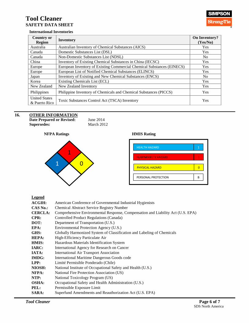
Tool Cleaner
SAFETY DATA SHEET
Tool Cleaner Page 6 of 7 SDS North America
International Inventories
16. OTHER INFORMATION Date Prepared or Revised: June 2014
Supersedes: March 2012
NFPA Ratings HMIS Rating
Legend
ACGIH: American Conference of Governmental Industrial Hygienists
CAS No.: Chemical Abstract Service Registry Number
CERCLA: Comprehensive Environmental Response, Compensation and Liability Act (U.S. EPA)
CPR: Controlled Product Regulations (Canada)
DOT: Department of Transportation (U.S.)
EPA: Environmental Protection Agency (U.S.)
GHS: Globally Harmonized System of Classification and Labeling of Chemicals
HEPA: High-Efficiency Particulate Air
HMIS: Hazardous Materials Identification System
IARC: International Agency for Research on Cancer
IATA: International Air Transport Association
IMDG: International Maritime Dangerous Goods code
LPP: Limité Permisible Ponderado (Chile)
NIOSH: National Institute of Occupational Safety and Health (U.S.)
NFPA: National Fire Protection Association (US)
NTP: National Toxicology Program (US)
OSHA: Occupational Safety and Health Administration (U.S.)
PEL: Permissible Exposure Limit
SARA: Superfund Amendments and Reauthorization Act (U.S. EPA)
Country or
Region Inventory
On Inventory?
(Yes/No)
Australia Australian Inventory of Chemical Substances (AICS) Yes
Canada Domestic Substances List (DSL) Yes
Canada Non-Domestic Substances List (NDSL) No
China Inventory of Existing Chemical Substances in China (IECSC) Yes
Europe European Inventory of Existing Commercial Chemical Substances (EINECS) Yes
Europe European List of Notified Chemical Substances (ELINCS) Yes
Japan Inventory of Existing and New Chemical Substances (ENCS) No
Korea Existing Chemicals List (ECL) Yes
New Zealand New Zealand Inventory Yes
Philippines Philippine Inventory of Chemicals and Chemical Substances (PICCS) Yes
United States
& Puerto Rico Toxic Substances Control Act (TSCA) Inventory Yes
HEALTH HAZARD
FLAMMABILTY HAZARD
PHYSICAL HAZARD
1
1
0
PERSONAL PROTECTION B
12 1 0

Tool Cleaner
SAFETY DATA SHEET
Tool Cleaner Page 7 of 7 SDS North America
SDS: Safety Data Sheet
STEL: Short Term Exposure Limit (15 minute Time Weighted Average)
STOT: Specific Target Organ Toxicity (GHS Classification)
TLV: Threshold Limit Value
TSCA: Toxic Substances Control Act (U.S.)
TWA: Time Weighted Average (exposure for 8-hour workday)
U.S.: United States
VOC: Volatile Organic Compounds
WHMIS: Canadian Workplace Hazardous Materials Information System
Safety Data Sheet (SDS) is prepared by Simpson Strong-Tie Co. in compliance with the requirements of OSHA 29
CFR Part 1910.1200. The information it contains is offered in good faith as accurate as of the date of this SDS. This
SDS is provided solely for the purpose of conveying health, safety, and environmental information. No warranty,
expressed or implied, is given. Health and Safety precautions may not be adequate for all individuals and/or
situations. It is the user's obligation to evaluate and use this product safely and to comply with all applicable laws
and regulations.
© 2014 Simpson Strong-Tie Company Inc.
FOR INTERNAL USE ONLY
GCNCL04:
XCOM3A

Tool Oil Lubricant
SAFETY DATA SHEET
Tool Oil Lubricant Page 1 of 6 SDS North America
1. IDENTIFICATION
Product Identifier: GCN-LU04 Recommended Use: Tool Oil Lubricant for use with Simpson Strong-Tie® Gas Concrete Nailer
Use Restrictions: None Known.
Company: Simpson Strong-Tie Company Inc.
Address: 5956 W. Las Positas Blvd.
Pleasanton, CA 94588 USA
Phone: 1-800-999-5099
Website: www.strongtie.com
Emergency: 1-800-535-5053 (US/Canada)
1-352-323-3500 (International)
For most current SDS, please visit our website at www.strongtie.com/sds
2. HAZARD IDENTIFICATION
Physical Hazards: Not Classified.
Health Hazard: Skin Corrosion/Irritation Category 3
Serious Eye Damage/Irritation Category 2B
Sensitization, Skin Category 1
Environmental Hazards: Not Classified.
Signal Word: WARNING!
Hazard Statements: May cause skin irritation. Causes eye irritation. May cause an allergic skin reaction.
Precautionary Statements:
Prevention: Wear protective gloves/protective clothing/eye protection/face protection. Avoid
breathing mist or vapor. Wash thoroughly after handling.
Response: If on skin: Wash with plenty of water. If skin irritation or rash occurs: Get medical
advice/attention. Take off contaminated clothing and wash before re-use. If in eyes: Rinse
cautiously with water for several minutes. Remove contact lenses, if present and easy to
do. Continue rinsing. If eye irritation persists: Get medical advice/attention.
Storage: Store in a well-ventilated place. Keep container tightly closed.
Disposal: Dispose of contents/container in accordance with local/regional/national regulations.
Hazards not otherwise Classified (HNOC): None known.
3. COMPOSITION INFORMATION
Chemical Name CAS Number Weight %
Highly refined mineral oils Mixture >97
DMSO-extract N/A < 3
Composition Note: This product is a mixture. Hazardous ingredients are listed above. May include other nonhazardous
ingredients. May include other trace ingredients, see Section 15.
4. FIRST-AID MEASURES
Eye Contact: Flush eyes with plenty of cool water for at least 15 minutes while holding the eyes open.
Remove contact lenses if present and easy to do. If redness, burning, blurred vision, or
swelling persists, consult a physician.
Skin Contact: Remove contaminated clothing and product, wash affected area with soap and water. Do
not apply greases or ointments. If rash or irritation persists consult a physician.
Ingestion: Rinse mouth. Do NOT induce vomiting. Consult a physician.
Inhalation: Remove patient to fresh air. Give oxygen or artificial respiration if needed. If patient
continues to experience difficulty breathing, consult a physician.

Tool Oil Lubricant
SAFETY DATA SHEET
Tool Oil Lubricant Page 2 of 6 SDS North America
Most Important Symptoms: Irritant effects. Symptoms include itching, burning, redness and tearing.
General Information: Provide general supportive measures and treat symptomatically. Symptoms may be
delayed. Ensure that medical personnel are aware of the material(s) involved, and take
precautions to protect themselves. If exposed or concerned: Get medical advice/attention.
Wash contaminated clothing before reuse.
5. FIRE-FIGHTING MEASURES
Suitable Extinguishing Media: Extinguish with foam, carbon dioxide, dry powder, or water fog.
Additional Information: None known.
Hazards during Fire-Fighting: Hazardous gases/vapors produced are carbon monoxide, carbon dioxide, and smoke.
Toxic and flammable vapors may be produced under combustion. Vapors are heavier
than air and may travel to ignition sources and flash back.
Fire-Fighting Procedures: Use standard fire-fighting procedures and consider the hazards of other involved
materials. In case of fire and/or explosion do not breathe fumes. Self-contained breathing
apparatus and full protective clothing must be worn. Move containers from fire area if
you can do so without risk. Cool containers with flooding quantities of water until well
after fire is out. Prevent runoff from fire control or dilution from entering streams,
sewers, or drinking water supply.
6. ACCIDENTAL RELEASE MEASURES
Personal Precautions: Keep unnecessary personnel away. Eliminate all ignition sources (no smoking, flares,
sparks, or flames in immediate area). Wear appropriate personal protective equipment.
Do not touch damaged containers or spilled material unless wearing appropriate
protective clothing. Avoid inhalation of vapors or mists. Ensure adequate ventilation.
Local authorities should be advised if significant spillages cannot be contained.
Clean-up Methods: Small spills: Wipe up with absorbent material (e.g. cloth, fleece). Place in leak-proof
containers. Seal tightly for proper disposal. Clean surface thoroughly to remove residual
contamination.
Large spills: Stop the flow of material, if this is without risk. Dike far ahead of spill to
contain material. Use a non-combustible material like vermiculite, sand or earth to soak
up the product. Place in leak-proof containers. Seal tightly for proper disposal. Following
product recovery, flush area with water. Prevent entry into waterways, sewer, basements
or confined areas.
Environmental Precautions: Avoid release to the environment. Contact local authorities in case of spillage to
drain/aquatic environment. Prevent further leakage or spillage if safe to do so.
7. HANDLING AND STORAGE
Handling: Mechanical ventilation or local exhaust ventilation is recommended. Keep away from
open flames, hot surfaces and sources of ignition. Wear appropriate personal protective
equipment. When using, do not eat, drink or smoke. Avoid contact with eyes, skin, and
clothing. Wash thoroughly after handling. Observe good industrial hygiene practices.
Storage: Store away from incompatible materials(see section 10 of the SDS). Keep in original
container, keep container tightly closed. Store in a cool, dry place out of direct sunlight.
Keep away from heat and sources of ignition.
8. EXPOSURE CONTROLS/PERSONAL PROTECTION
Protective Measure: Wear appropriate personal protective equipment.
Eye Protection: Wear chemical splash goggles or safety glasses with side shield.
Hand Protection: Wear chemical-resistant gloves such as: Nitrile, neoprene, butyl.
Skin and Body Protection: Wear long sleeve shirt/long pants and other clothing as required to minimize contact.
Respirator Protection: Not required for properly ventilated areas. NIOSH or MSHA approved air-purifying
respirators should to control exposures when ventilation or other controls are inadequate
or discomfort or irritation is experienced.
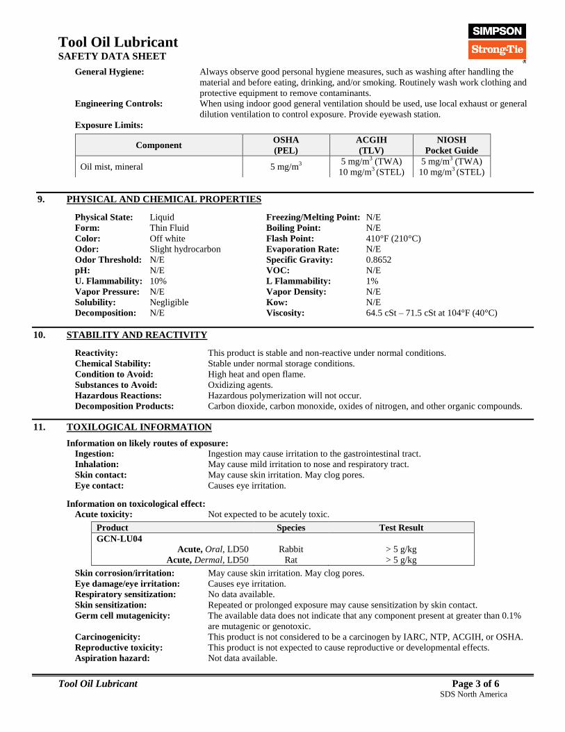
Tool Oil Lubricant
SAFETY DATA SHEET
Tool Oil Lubricant Page 3 of 6 SDS North America
General Hygiene: Always observe good personal hygiene measures, such as washing after handling the
material and before eating, drinking, and/or smoking. Routinely wash work clothing and
protective equipment to remove contaminants.
Engineering Controls: When using indoor good general ventilation should be used, use local exhaust or general
dilution ventilation to control exposure. Provide eyewash station.
After Cur Exposure Limits:
9. PHYSICAL AND CHEMICAL PROPERTIES
Physical State: Liquid Freezing/Melting Point: N/E
Form: Thin Fluid Boiling Point: N/E
Color: Off white Flash Point: 410°F (210°C)
Odor: Slight hydrocarbon Evaporation Rate: N/E
Odor Threshold: N/E Specific Gravity: 0.8652
pH: N/E VOC: N/E
U. Flammability: 10% L Flammability: 1%
Vapor Pressure: N/E Vapor Density: N/E
Solubility: Negligible Kow: N/E
Decomposition: N/E Viscosity: 64.5 cSt – 71.5 cSt at 104°F (40°C)
10. STABILITY AND REACTIVITY
Reactivity: This product is stable and non-reactive under normal conditions.
Chemical Stability: Stable under normal storage conditions.
Condition to Avoid: High heat and open flame.
Substances to Avoid: Oxidizing agents.
Hazardous Reactions: Hazardous polymerization will not occur.
Decomposition Products: Carbon dioxide, carbon monoxide, oxides of nitrogen, and other organic compounds.
11. TOXILOGICAL INFORMATION
Information on likely routes of exposure:
Ingestion: Ingestion may cause irritation to the gastrointestinal tract.
Inhalation: May cause mild irritation to nose and respiratory tract.
Skin contact: May cause skin irritation. May clog pores.
Eye contact: Causes eye irritation.
Information on toxicological effect:
Acute toxicity: Not expected to be acutely toxic.
Product Species Test Result
GCN-LU04
Acute, Oral, LD50 Rabbit > 5 g/kg
Acute, Dermal, LD50 Rat > 5 g/kg
Skin corrosion/irritation: May cause skin irritation. May clog pores.
Eye damage/eye irritation: Causes eye irritation.
Respiratory sensitization: No data available.
Skin sensitization: Repeated or prolonged exposure may cause sensitization by skin contact.
Germ cell mutagenicity: The available data does not indicate that any component present at greater than 0.1%
are mutagenic or genotoxic.
Carcinogenicity: This product is not considered to be a carcinogen by IARC, NTP, ACGIH, or OSHA.
Reproductive toxicity: This product is not expected to cause reproductive or developmental effects.
Aspiration hazard: Not data available.
Component OSHA
(PEL)
ACGIH
(TLV)
NIOSH
Pocket Guide
Oil mist, mineral 5 mg/m3
5 mg/m3 (TWA)
10 mg/m3 (STEL)
5 mg/m3 (TWA)
10 mg/m3 (STEL)

Tool Oil Lubricant
SAFETY DATA SHEET
Tool Oil Lubricant Page 4 of 6 SDS North America
Specific target organ toxicity:
Single exposure May cause drowsiness or dizziness.
Repeated exposure No data available.
Further information: Toxicological, ecotoxicological, physical, and chemical properties may not have been
fully investigated. Hazard data above is estimated based on best available information.
Some workers with certain pre-existing medical conditions such as: asthma, allergies,
or impaired pulmonary and/or liver functions, or who may be particularly susceptible
to this material, may be affected by exposure to this material.
12. ECOLOGICAL INFORMATION
Ecotoxicity: Information given is based on data on the components and the ecotoxicology of similar
products. The product is not classified as environmentally hazardous. . However, this
does not exclude the possibility that large or repeated spills can have a harmful or
damaging effect on the environment.
Persistence and degradability: Not soluble in water. Not expected to be readily biodegradable.
Bioaccumulative potential: Not expected to bioaccumulate.
Mobility in soil: No data available.
Other adverse effects: No other adverse environmental effects (e.g. ozone depletion, photochemical ozone
creation potential, endocrine disruption) are expected from this product.
13. DISPOSAL CONSIDERATIONS
Waste Disposal of Substance: Do not allow this material to drain into sewers/water supplies. Do not contaminate
ponds, waterways or ditches with chemical or used container. Dispose of
contents/container in accordance with local/regional/national/international regulations.
Container Disposal: Empty containers or liners may retain some product residues; follow label warnings
even after container is emptied. Empty containers should be taken to an approved waste
handling site for recycling or disposal.
14. TRANSPORTATION INFORMATION
United States Department of Transportation (USDOT): Not regulated for transport by DOT.
International Air Transportation Association (IATA): Not regulated as a hazardous material.
International Maritime Dangerous Goods Code (IMDG): Not regulated as a hazardous material.
Special precautions for user: Read safety instructions, SDS and emergency procedures before handling.
Transport in bulk according to Annex II of MARPOL 73/78 and the IBC Code: Not applicable.
This information does not cover all specific regulatory or operational requirements of this product. The classifications for
transportation may vary by container volume or different regional or national regulations.
15. REGULATORY INFORMATION
US Federal Regulations This product is a "Hazardous Chemical" as defined by the OSHA Hazard
Communication Standard, 29 CFR 1910.1200.
TSCA Section 12(b) Export Notification (40 CFR 707, Subpt. D) Not regulated.
US. OSHA Specifically Regulated Substances (29 CFR 1910.1001-1050) Not listed.
CERCLA Hazardous Substance List (40 CFR 302.4) Not Regulated.
Superfund Amendments and Reauthorization Act of 1986 (SARA)
Hazard categories Immediate Hazard No
Delayed Hazard No
Fire Hazard No
Pressure Hazard No
Reactivity Hazard No
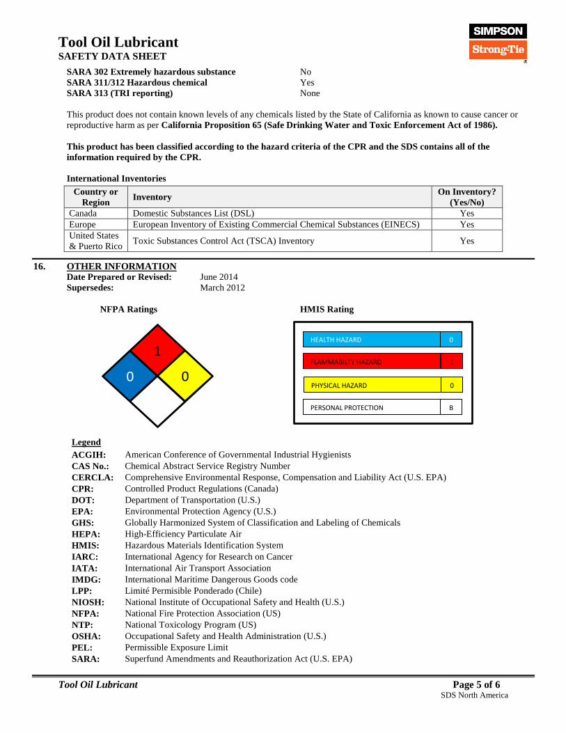
Tool Oil Lubricant
SAFETY DATA SHEET
Tool Oil Lubricant Page 5 of 6 SDS North America
SARA 302 Extremely hazardous substance No
SARA 311/312 Hazardous chemical Yes
SARA 313 (TRI reporting) None
This product does not contain known levels of any chemicals listed by the State of California as known to cause cancer or
reproductive harm as per California Proposition 65 (Safe Drinking Water and Toxic Enforcement Act of 1986).
This product has been classified according to the hazard criteria of the CPR and the SDS contains all of the
information required by the CPR.
International Inventories
16. OTHER INFORMATION Date Prepared or Revised: June 2014
Supersedes: March 2012
NFPA Ratings HMIS Rating
Legend
ACGIH: American Conference of Governmental Industrial Hygienists
CAS No.: Chemical Abstract Service Registry Number
CERCLA: Comprehensive Environmental Response, Compensation and Liability Act (U.S. EPA)
CPR: Controlled Product Regulations (Canada)
DOT: Department of Transportation (U.S.)
EPA: Environmental Protection Agency (U.S.)
GHS: Globally Harmonized System of Classification and Labeling of Chemicals
HEPA: High-Efficiency Particulate Air
HMIS: Hazardous Materials Identification System
IARC: International Agency for Research on Cancer
IATA: International Air Transport Association
IMDG: International Maritime Dangerous Goods code
LPP: Limité Permisible Ponderado (Chile)
NIOSH: National Institute of Occupational Safety and Health (U.S.)
NFPA: National Fire Protection Association (US)
NTP: National Toxicology Program (US)
OSHA: Occupational Safety and Health Administration (U.S.)
PEL: Permissible Exposure Limit
SARA: Superfund Amendments and Reauthorization Act (U.S. EPA)
Country or
Region Inventory
On Inventory?
(Yes/No)
Canada Domestic Substances List (DSL) Yes
Europe European Inventory of Existing Commercial Chemical Substances (EINECS) Yes
United States
& Puerto Rico Toxic Substances Control Act (TSCA) Inventory Yes
HEALTH HAZARD
FLAMMABILTY HAZARD
PHYSICAL HAZARD
0
1
0
PERSONAL PROTECTION B
12
0 0

Tool Oil Lubricant
SAFETY DATA SHEET
Tool Oil Lubricant Page 6 of 6 SDS North America
SDS: Safety Data Sheet
STEL: Short Term Exposure Limit (15 minute Time Weighted Average)
STOT: Specific Target Organ Toxicity (GHS Classification)
TLV: Threshold Limit Value
TSCA: Toxic Substances Control Act (U.S.)
TWA: Time Weighted Average (exposure for 8-hour workday)
U.S.: United States
VOC: Volatile Organic Compounds
WHMIS: Canadian Workplace Hazardous Materials Information System
Safety Data Sheet (SDS) is prepared by Simpson Strong-Tie Co. in compliance with the requirements of OSHA 29
CFR Part 1910.1200. The information it contains is offered in good faith as accurate as of the date of this SDS. This
SDS is provided solely for the purpose of conveying health, safety, and environmental information. No warranty,
expressed or implied, is given. Health and Safety precautions may not be adequate for all individuals and/or
situations. It is the user's obligation to evaluate and use this product safely and to comply with all applicable laws
and regulations.
© 2014 Simpson Strong-Tie Company Inc.
FOR INTERNAL USE ONLY
GCNLU04:
XCOM3B