CROUZET TEMPERATURE CONTROLLERS. CT 48 CTD 43, CTD 46, & CTH 46 CTD 24 MIC 48.
SCHEDULE TYPE:
PROJECT:
ENGINEER:CONTRACTOR:
DATE B SERIES SUPERSEDES DRAWING NO.
10 - 13 - 09 5000 31 - 8 - 00RR 5000-CTD
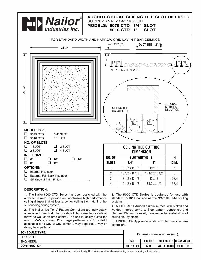
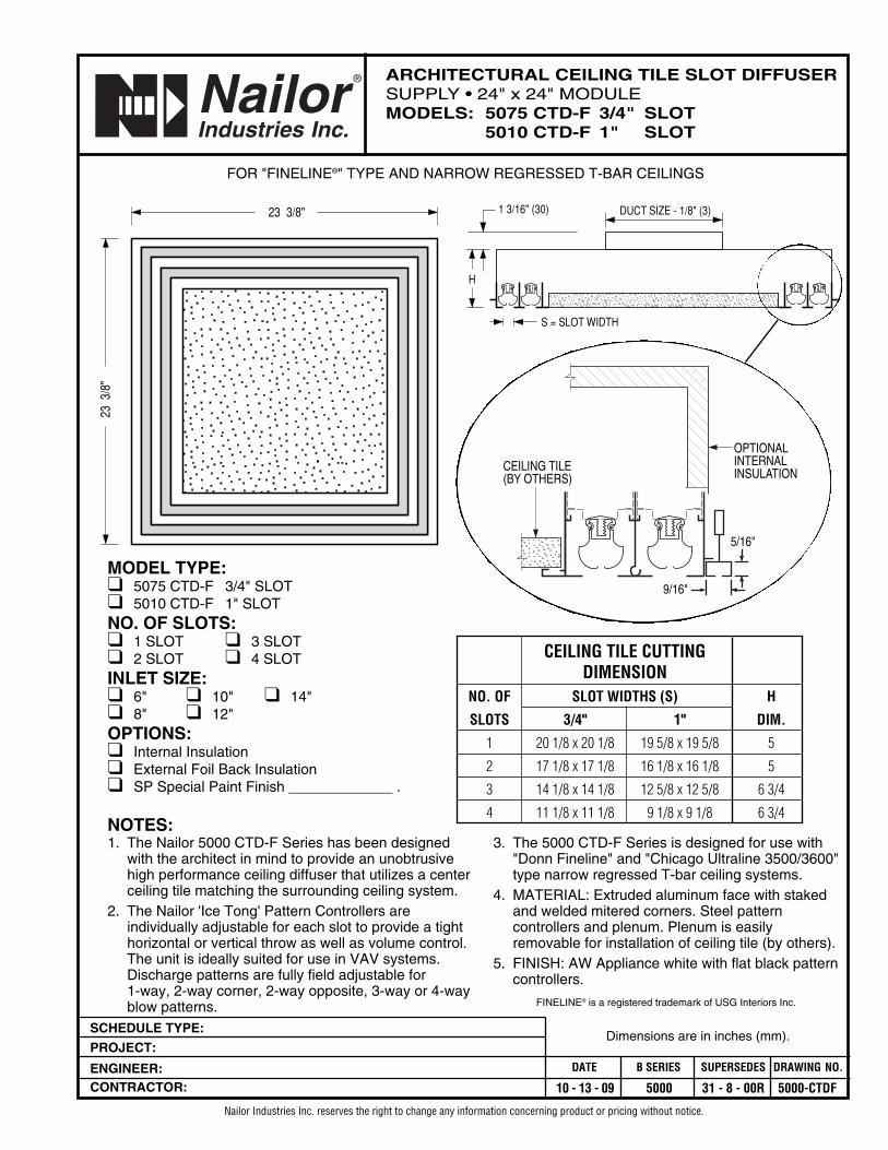
ARCHITECTURAL CEILING TILE SLOT DIFFUSERSUPPLY • 24" x 24" MODULEMODELS: 5075 CTD 3/4" SLOT
5010 CTD 1" SLOT
Nailor Industries Inc. reserves the right to change any information concerning product or pricing without notice.
Dimensions are in inches (mm).
DESCRIPTION:
1. The Nailor 5000 CTD Series has been designed with thearchitect in mind to provide an unobtrusive high performanceceiling diffuser that utilizes a center ceiling tile matching thesurrounding ceiling system.
2. The Nailor 'Ice Tong' Pattern Controllers are individuallyadjustable for each slot to provide a tight horizontal or verticalthrow as well as volume control. The unit is ideally suited foruse in VAV systems. Discharge patterns are fully fieldadjustable for 1-way, 2-way corner, 2-way opposite, 3-way or4-way blow patterns.
FOR STANDARD WIDTH AND NARROW GRID LAY-IN T-BAR CEILINGS
MODEL TYPE:❑ 5075 CTD 3/4" SLOT❑ 5010 CTD 1" SLOT
NO. OF SLOTS:❑ 1 SLOT ❑ 3 SLOT❑ 2 SLOT ❑ 4 SLOT
INLET SIZE:❑ 6" ❑ 10" ❑ 14"❑ 8" ❑ 12"
OPTIONS:❑ Internal Insulation❑ External Foil Back Insulation❑ SP Special Paint Finish _________________ .
23 3/4"
23 3
/4"
S = SLOT WIDTH
1 3/16" (30) DUCT SIZE - 1/8" (3)
H
3. The 5000 CTD Series is designed for use withstandard 15/16" T-bar and narrow 9/16" flat T-bar ceilingsystems.
4. MATERIAL: Extruded aluminum face with staked andwelded mitered corners. Steel pattern controllers andplenum. Plenum is easily removable for installation ofceiling tile (by others).
5. FINISH: AW Appliance white with flat black patterncontrollers.
CEILING TILE(BY OTHERS)
OPTIONALINTERNALINSULATION
CEILING TILE CUTTINGDIMENSION
NO. OF SLOT WIDTHS (S) H
SLOTS 3/4" 1" DIM.
1 19 1/2 x 19 1/2 19 x 19 5
2 16 1/2 x 16 1/2 15 1/2 x 15 1/2 5
3 13 1/2 x 13 1/2 12 x 12 6 3/4
4 10 1/2 x 10 1/2 8 1/2 x 8 1/2 6 3/4
SCHEDULE TYPE:
PROJECT:
ENGINEER:CONTRACTOR:
DATE B SERIES SUPERSEDES DRAWING NO.
10 - 13 - 09 5000 31 - 8 - 00R 5000-CTDF
ARCHITECTURAL CEILING TILE SLOT DIFFUSERSUPPLY • 24" x 24" MODULEMODELS: 5075 CTD-F 3/4" SLOT
5010 CTD-F 1" SLOT
Nailor Industries Inc. reserves the right to change any information concerning product or pricing without notice.
Dimensions are in inches (mm).
NOTES:1. The Nailor 5000 CTD-F Series has been designed
with the architect in mind to provide an unobtrusive high performance ceiling diffuser that utilizes a center ceiling tile matching the surrounding ceiling system.
2. The Nailor 'Ice Tong' Pattern Controllers are individually adjustable for each slot to provide a tight horizontal or vertical throw as well as volume control. The unit is ideally suited for use in VAV systems. Discharge patterns are fully field adjustable for 1-way, 2-way corner, 2-way opposite, 3-way or 4-way blow patterns.
FOR "FINELINE®" TYPE AND NARROW REGRESSED T-BAR CEILINGS
MODEL TYPE:❑ 5075 CTD-F 3/4" SLOT❑ 5010 CTD-F 1" SLOTNO. OF SLOTS:❑ 1 SLOT ❑ 3 SLOT❑ 2 SLOT ❑ 4 SLOTINLET SIZE:❑ 6" ❑ 10" ❑ 14"❑ 8" ❑ 12"OPTIONS:❑ Internal Insulation❑ External Foil Back Insulation❑ SP Special Paint Finish _____________ .
23 3/8"
23 3
/8"
S = SLOT WIDTH
1 3/16" (30) DUCT SIZE - 1/8" (3)
H
3. The 5000 CTD-F Series is designed for use with "Donn Fineline" and "Chicago Ultraline 3500/3600" type narrow regressed T-bar ceiling systems.
4. MATERIAL: Extruded aluminum face with staked and welded mitered corners. Steel pattern controllers and plenum. Plenum is easily removable for installation of ceiling tile (by others).
5. FINISH: AW Appliance white with flat black pattern controllers.
FINELINE® is a registered trademark of USG Interiors Inc.
CEILING TILE(BY OTHERS)
OPTIONALINTERNALINSULATION
5/16"
9/16"
CEILING TILE CUTTINGDIMENSION
NO. OF SLOT WIDTHS (S) H
SLOTS 3/4" 1" DIM.
1 20 1/8 x 20 1/8 19 5/8 x 19 5/8 5
2 17 1/8 x 17 1/8 16 1/8 x 16 1/8 5
3 14 1/8 x 14 1/8 12 5/8 x 12 5/8 6 3/4
4 11 1/8 x 11 1/8 9 1/8 x 9 1/8 6 3/4
SCHEDULE TYPE:
PROJECT:
ENGINEER:CONTRACTOR:
DATE B SERIES SUPERSEDES DRAWING NO.
10 - 13 - 09 5000 31 - 8 - 00R 5000R-CTD
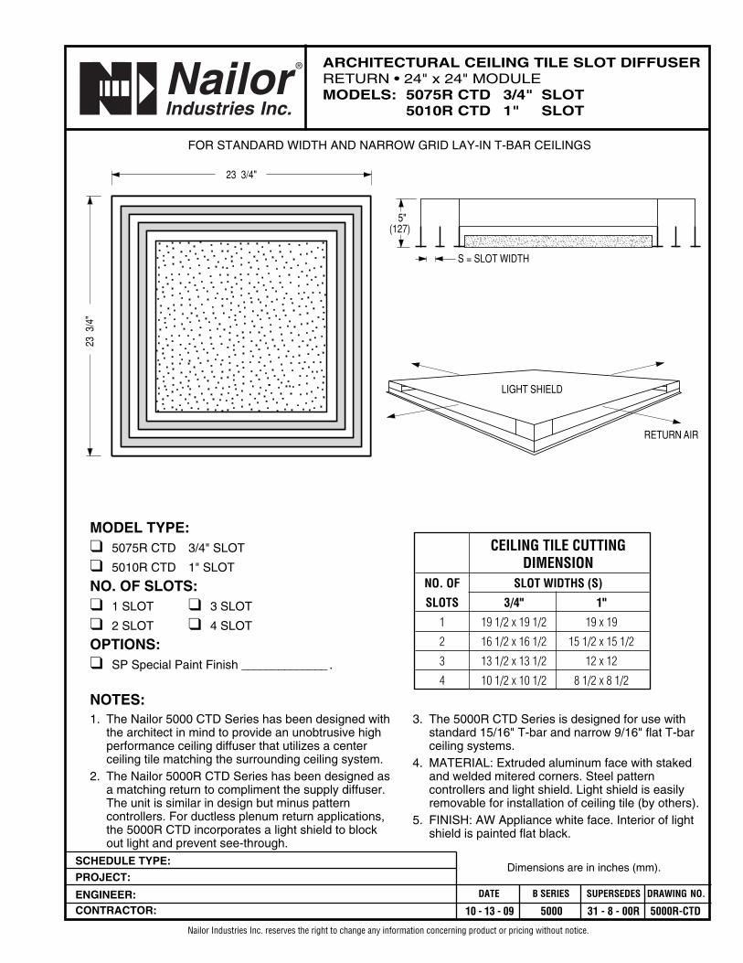
ARCHITECTURAL CEILING TILE SLOT DIFFUSERRETURN • 24" x 24" MODULEMODELS: 5075R CTD 3/4" SLOT
5010R CTD 1" SLOT
Nailor Industries Inc. reserves the right to change any information concerning product or pricing without notice.
Dimensions are in inches (mm).
NOTES:1. The Nailor 5000 CTD Series has been designed with
the architect in mind to provide an unobtrusive high performance ceiling diffuser that utilizes a center ceiling tile matching the surrounding ceiling system.
2. The Nailor 5000R CTD Series has been designed as a matching return to compliment the supply diffuser. The unit is similar in design but minus pattern controllers. For ductless plenum return applications, the 5000R CTD incorporates a light shield to block out light and prevent see-through.
FOR STANDARD WIDTH AND NARROW GRID LAY-IN T-BAR CEILINGS
MODEL TYPE:❑ 5075R CTD 3/4" SLOT
❑ 5010R CTD 1" SLOT
NO. OF SLOTS:❑ 1 SLOT ❑ 3 SLOT
❑ 2 SLOT ❑ 4 SLOT
OPTIONS:❑ SP Special Paint Finish ______________ .
23 3/4"
23 3
/4"
S = SLOT WIDTH
5"(127)
3. The 5000R CTD Series is designed for use with standard 15/16" T-bar and narrow 9/16" flat T-bar ceiling systems.
4. MATERIAL: Extruded aluminum face with staked and welded mitered corners. Steel pattern controllers and light shield. Light shield is easily removable for installation of ceiling tile (by others).
5. FINISH: AW Appliance white face. Interior of light shield is painted flat black.
CEILING TILE CUTTINGDIMENSION
NO. OF SLOT WIDTHS (S)
SLOTS 3/4" 1"
1 19 1/2 x 19 1/2 19 x 19
2 16 1/2 x 16 1/2 15 1/2 x 15 1/2
3 13 1/2 x 13 1/2 12 x 12
4 10 1/2 x 10 1/2 8 1/2 x 8 1/2
LIGHT SHIELD
RETURN AIR
SCHEDULE TYPE:
PROJECT:
ENGINEER:CONTRACTOR:
DATE B SERIES SUPERSEDES DRAWING NO.
10 - 13 - 09 5000 31 - 8 - 00R 5000R-CTDF
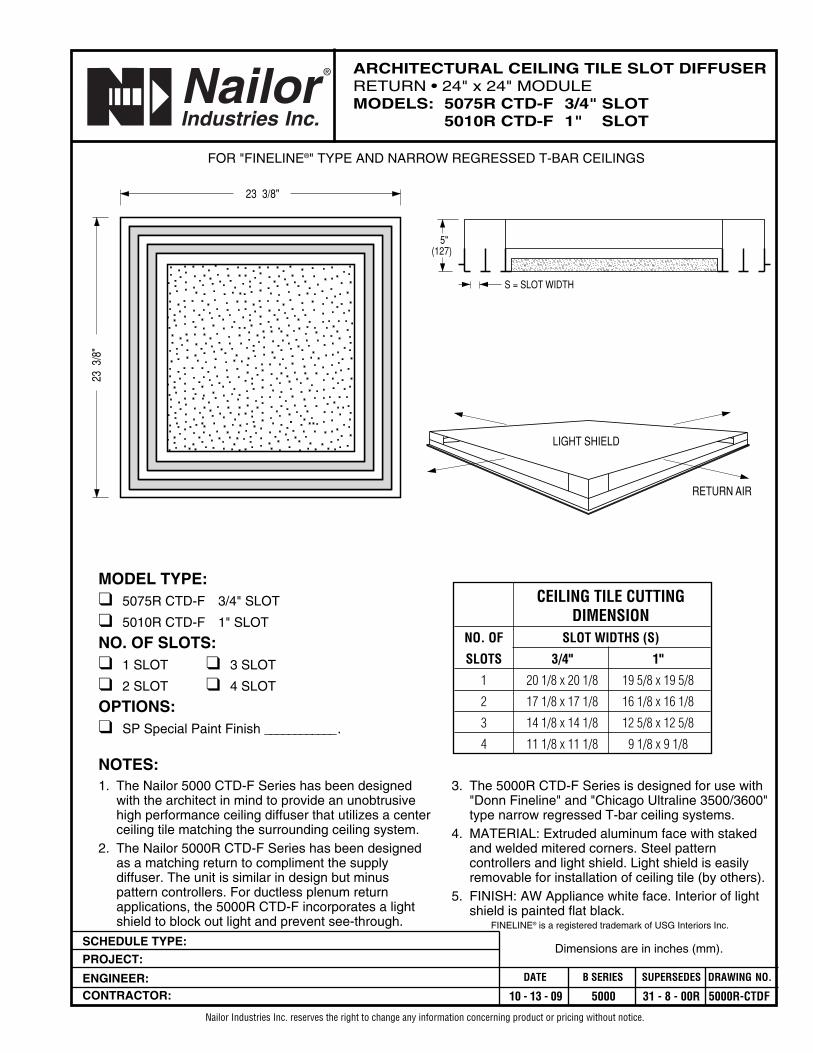
ARCHITECTURAL CEILING TILE SLOT DIFFUSERRETURN • 24" x 24" MODULEMODELS: 5075R CTD-F 3/4" SLOT
5010R CTD-F 1" SLOT
Nailor Industries Inc. reserves the right to change any information concerning product or pricing without notice.
Dimensions are in inches (mm).
NOTES:1. The Nailor 5000 CTD-F Series has been designed
with the architect in mind to provide an unobtrusive high performance ceiling diffuser that utilizes a center ceiling tile matching the surrounding ceiling system.
2. The Nailor 5000R CTD-F Series has been designed as a matching return to compliment the supply diffuser. The unit is similar in design but minus pattern controllers. For ductless plenum return applications, the 5000R CTD-F incorporates a light shield to block out light and prevent see-through.
FOR "FINELINE®" TYPE AND NARROW REGRESSED T-BAR CEILINGS
MODEL TYPE:❑ 5075R CTD-F 3/4" SLOT
❑ 5010R CTD-F 1" SLOT
NO. OF SLOTS:❑ 1 SLOT ❑ 3 SLOT
❑ 2 SLOT ❑ 4 SLOT
OPTIONS:❑ SP Special Paint Finish ____________ .
23 3/8"
23 3
/8"
S = SLOT WIDTH
5"(127)
3. The 5000R CTD-F Series is designed for use with "Donn Fineline" and "Chicago Ultraline 3500/3600" type narrow regressed T-bar ceiling systems.
4. MATERIAL: Extruded aluminum face with staked and welded mitered corners. Steel pattern controllers and light shield. Light shield is easily removable for installation of ceiling tile (by others).
5. FINISH: AW Appliance white face. Interior of light shield is painted flat black.
FINELINE® is a registered trademark of USG Interiors Inc.
LIGHT SHIELD
RETURN AIR
CEILING TILE CUTTINGDIMENSION
NO. OF SLOT WIDTHS (S)
SLOTS 3/4" 1"
1 20 1/8 x 20 1/8 19 5/8 x 19 5/8
2 17 1/8 x 17 1/8 16 1/8 x 16 1/8
3 14 1/8 x 14 1/8 12 5/8 x 12 5/8
4 11 1/8 x 11 1/8 9 1/8 x 9 1/8
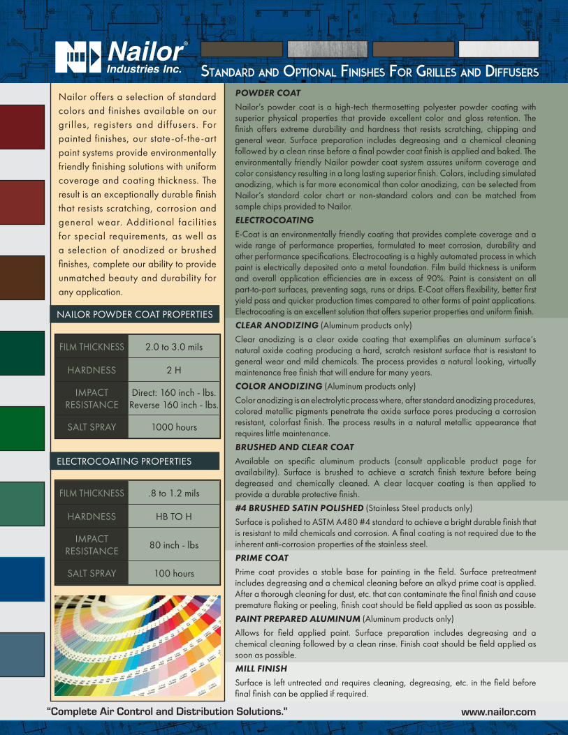
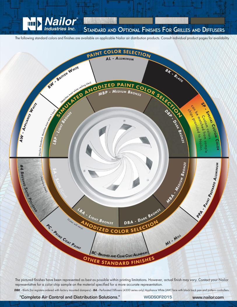
Standard and OptiOnal FiniSheS FOr GrilleS and diFFuSerS
Nailor offers a selection of standard colors and finishes available on our gril les, registers and dif fusers. For painted finishes, our state-of-the-art paint systems provide environmentally friendly finishing solutions with uniform coverage and coating thickness. The result is an exceptionally durable finish that resists scratching, corrosion and general wear. Additional facili t ies for special requirements, as well as a selection of anodized or brushed finishes, complete our ability to provide unmatched beauty and durability for any application.
POWDER COATNailor’s powder coat is a high-tech thermosetting polyester powder coating with superior physical properties that provide excellent color and gloss retention. The finish offers extreme durability and hardness that resists scratching, chipping and general wear. Surface preparation includes degreasing and a chemical cleaning followed by a clean rinse before a final powder coat finish is applied and baked. The environmentally friendly Nailor powder coat system assures uniform coverage and color consistency resulting in a long lasting superior finish. Colors, including simulated anodizing, which is far more economical than color anodizing, can be selected from Nailor’s standard color chart or non-standard colors and can be matched from sample chips provided to Nailor.
ELECTROCOATINGE-Coat is an environmentally friendly coating that provides complete coverage and a wide range of performance properties, formulated to meet corrosion, durability and other performance specifications. Electrocoating is a highly automated process in which paint is electrically deposited onto a metal foundation. Film build thickness is uniform and overall application efficiencies are in excess of 90%. Paint is consistent on all part-to-part surfaces, preventing sags, runs or drips. E-Coat offers flexibility, better first yield pass and quicker production times compared to other forms of paint applications. Electrocoating is an excellent solution that offers superior properties and uniform finish.
CLEAR ANODIZING (Aluminum products only)
Clear anodizing is a clear oxide coating that exemplifies an aluminum surface’s natural oxide coating producing a hard, scratch resistant surface that is resistant to general wear and mild chemicals. The process provides a natural looking, virtually maintenance free finish that will endure for many years.
COLOR ANODIZING (Aluminum products only)
Color anodizing is an electrolytic process where, after standard anodizing procedures, colored metallic pigments penetrate the oxide surface pores producing a corrosion resistant, colorfast finish. The process results in a natural metallic appearance that requires little maintenance.
BRUSHED AND CLEAR COATAvailable on specific aluminum products (consult applicable product page for availability). Surface is brushed to achieve a scratch finish texture before being degreased and chemically cleaned. A clear lacquer coating is then applied to provide a durable protective finish.
#4 BRUSHED SATIN POLISHED (Stainless Steel products only)
Surface is polished to ASTM A480 #4 standard to achieve a bright durable finish that is resistant to mild chemicals and corrosion. A final coating is not required due to the inherent anti-corrosion properties of the stainless steel.
PRIME COATPrime coat provides a stable base for painting in the field. Surface pretreatment includes degreasing and a chemical cleaning before an alkyd prime coat is applied. After a thorough cleaning for dust, etc. that can contaminate the final finish and cause premature flaking or peeling, finish coat should be field applied as soon as possible.
PAINT PREPARED ALUMINUM (Aluminum products only)
Allows for field applied paint. Surface preparation includes degreasing and a chemical cleaning followed by a clean rinse. Finish coat should be field applied as soon as possible.
MILL FINISHSurface is left untreated and requires cleaning, degreasing, etc. in the field before final finish can be applied if required.
NAILOR POWDER COAT PROPERTIES
ELECTROCOATING PROPERTIES
FILM THICKNESS 2.0 to 3.0 mils
HARDNESS 2 H
IMPACT RESISTANCE
Direct: 160 inch - lbs.Reverse 160 inch - lbs.
SALT SPRAY 1000 hours
FILM THICKNESS .8 to 1.2 mils
HARDNESS HB TO H
IMPACT RESISTANCE
80 inch - lbs
SALT SPRAY 100 hours
“Complete Air Control and Distribution Solutions.” www.nailor.com
Standard and OptiOnal FiniSheS FOr GrilleS and diFFuSerS
The following standard colors and finishes are available on applicable Nailor air distribution products. Consult individual product pages for availability
The pictured finishes have been represented as best as possible within printing limitations. However, actual finish may vary. Contact your Nailor representative for a color chip sample on the material specified for a more accurate representation.
DBK - Black (for registers ordered with factory mounted dampers) - BA - Perforated Diffusers (4300 series only) Appliance White (AW) face with black back pan and pattern controllers.
WGDSOF2015“Complete Air Control and Distribution Solutions.” www.nailor.com
D132
CEI
LIN
G D
IFFU
SERS
D
ARCHITECTURAL SQUARE CEILING DIFFUSERS
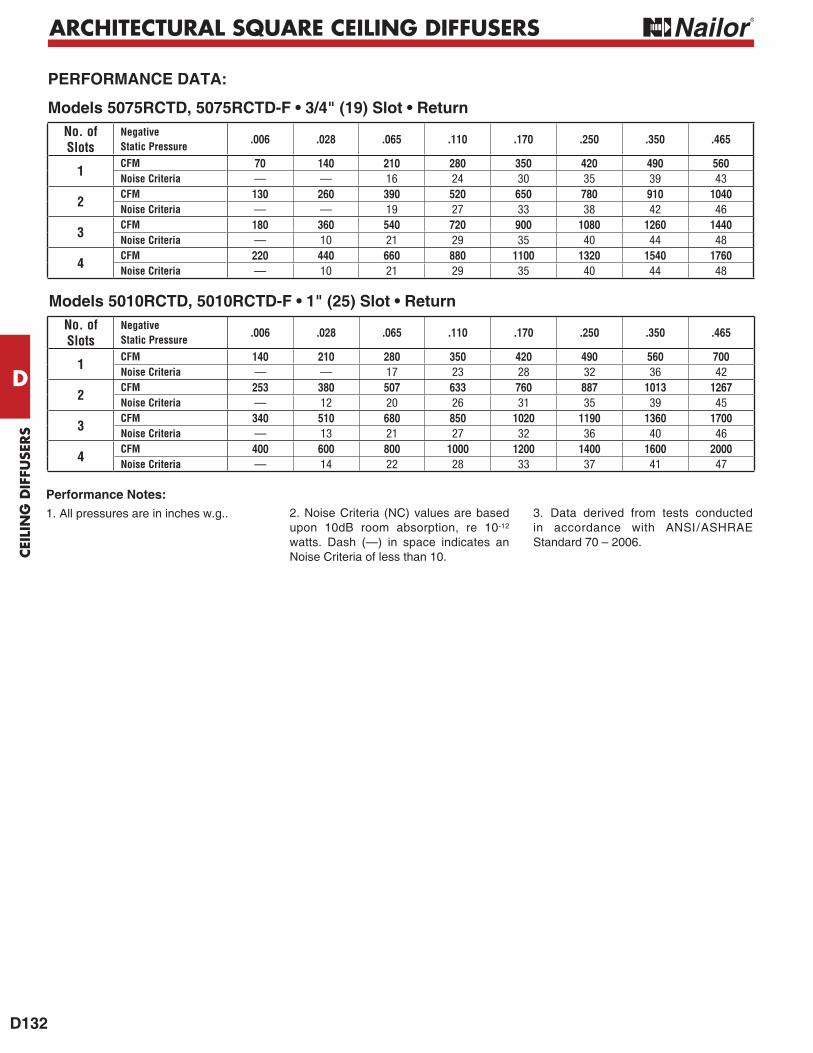
Models 5010RCTD, 5010RCTD-F • 1" (25) Slot • Return
PERFORMANCE DATA:
Models 5075RCTD, 5075RCTD-F • 3/4" (19) Slot • ReturnNo. ofSlots
NegativeStatic Pressure
.006 .028 .065 .110 .170 .250 .350 .465
1CFM 70 140 210 280 350 420 490 560Noise Criteria — — 16 24 30 35 39 43
2CFM 130 260 390 520 650 780 910 1040Noise Criteria — — 19 27 33 38 42 46
3CFM 180 360 540 720 900 1080 1260 1440Noise Criteria — 10 21 29 35 40 44 48
4CFM 220 440 660 880 1100 1320 1540 1760Noise Criteria — 10 21 29 35 40 44 48
No. ofSlots
NegativeStatic Pressure
.006 .028 .065 .110 .170 .250 .350 .465
1CFM 140 210 280 350 420 490 560 700Noise Criteria — — 17 23 28 32 36 42
2CFM 253 380 507 633 760 887 1013 1267Noise Criteria — 12 20 26 31 35 39 45
3CFM 340 510 680 850 1020 1190 1360 1700Noise Criteria — 13 21 27 32 36 40 46
4CFM 400 600 800 1000 1200 1400 1600 2000Noise Criteria — 14 22 28 33 37 41 47
Performance Notes:1. All pressures are in inches w.g.. 2. Noise Criteria (NC) values are based
upon 10dB room absorption, re 10-12
watts. Dash (—) in space indicates an Noise Criteria of less than 10.
3. Data derived from tests conducted in accordance with ANSI/ASHRAE Standard 70 – 2006.
D131
CEILIN
G D
IFFUSER
S
D
ARCHITECTURAL SQUARE CEILING DIFFUSERS
PERFORMANCE DATA:
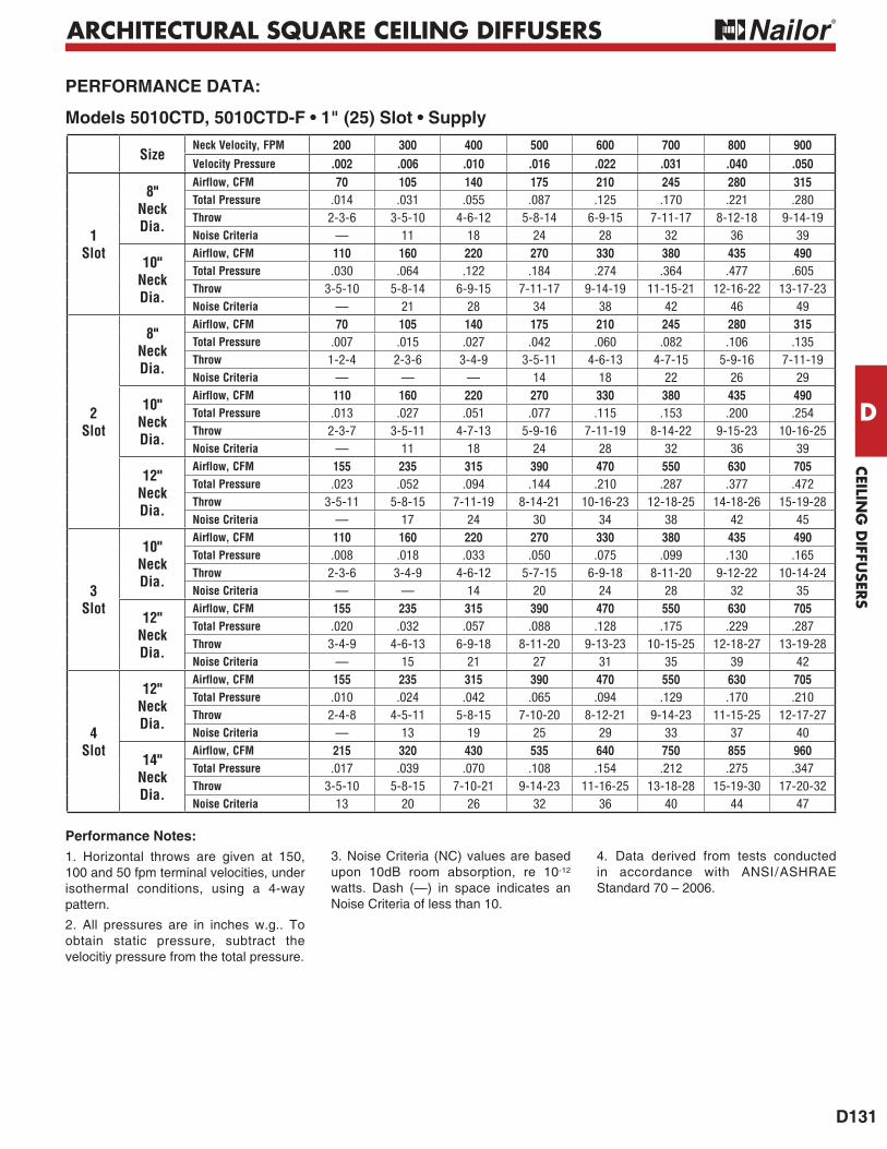
Models 5010CTD, 5010CTD-F • 1" (25) Slot • Supply
Performance Notes:1. Horizontal throws are given at 150, 100 and 50 fpm terminal velocities, under isothermal conditions, using a 4-way pattern.
2. All pressures are in inches w.g.. To obtain static pressure, subtract the velocitiy pressure from the total pressure.
3. Noise Criteria (NC) values are based upon 10dB room absorption, re 10-12
watts. Dash (—) in space indicates an Noise Criteria of less than 10.
4. Data derived from tests conducted in accordance with ANSI/ASHRAE Standard 70 – 2006.
SizeNeck Velocity, FPM 200 300 400 500 600 700 800 900Velocity Pressure .002 .006 .010 .016 .022 .031 .040 .050
1Slot
8"NeckDia.
Airflow, CFM 70 105 140 175 210 245 280 315Total Pressure .014 .031 .055 .087 .125 .170 .221 .280Throw 2-3-6 3-5-10 4-6-12 5-8-14 6-9-15 7-11-17 8-12-18 9-14-19Noise Criteria — 11 18 24 28 32 36 39
10"NeckDia.
Airflow, CFM 110 160 220 270 330 380 435 490Total Pressure .030 .064 .122 .184 .274 .364 .477 .605Throw 3-5-10 5-8-14 6-9-15 7-11-17 9-14-19 11-15-21 12-16-22 13-17-23Noise Criteria — 21 28 34 38 42 46 49
2Slot
8"NeckDia.
Airflow, CFM 70 105 140 175 210 245 280 315Total Pressure .007 .015 .027 .042 .060 .082 .106 .135Throw 1-2-4 2-3-6 3-4-9 3-5-11 4-6-13 4-7-15 5-9-16 7-11-19Noise Criteria — — — 14 18 22 26 29
10"NeckDia.
Airflow, CFM 110 160 220 270 330 380 435 490Total Pressure .013 .027 .051 .077 .115 .153 .200 .254Throw 2-3-7 3-5-11 4-7-13 5-9-16 7-11-19 8-14-22 9-15-23 10-16-25Noise Criteria — 11 18 24 28 32 36 39
12"NeckDia.
Airflow, CFM 155 235 315 390 470 550 630 705Total Pressure .023 .052 .094 .144 .210 .287 .377 .472Throw 3-5-11 5-8-15 7-11-19 8-14-21 10-16-23 12-18-25 14-18-26 15-19-28Noise Criteria — 17 24 30 34 38 42 45
3Slot
10"NeckDia.
Airflow, CFM 110 160 220 270 330 380 435 490Total Pressure .008 .018 .033 .050 .075 .099 .130 .165Throw 2-3-6 3-4-9 4-6-12 5-7-15 6-9-18 8-11-20 9-12-22 10-14-24Noise Criteria — — 14 20 24 28 32 35
12"NeckDia.
Airflow, CFM 155 235 315 390 470 550 630 705Total Pressure .020 .032 .057 .088 .128 .175 .229 .287Throw 3-4-9 4-6-13 6-9-18 8-11-20 9-13-23 10-15-25 12-18-27 13-19-28Noise Criteria — 15 21 27 31 35 39 42
4Slot
12"NeckDia.
Airflow, CFM 155 235 315 390 470 550 630 705Total Pressure .010 .024 .042 .065 .094 .129 .170 .210Throw 2-4-8 4-5-11 5-8-15 7-10-20 8-12-21 9-14-23 11-15-25 12-17-27Noise Criteria — 13 19 25 29 33 37 40
14"NeckDia.
Airflow, CFM 215 320 430 535 640 750 855 960Total Pressure .017 .039 .070 .108 .154 .212 .275 .347Throw 3-5-10 5-8-15 7-10-21 9-14-23 11-16-25 13-18-28 15-19-30 17-20-32Noise Criteria 13 20 26 32 36 40 44 47
D130
CEI
LIN
G D
IFFU
SERS
D
ARCHITECTURAL SQUARE CEILING DIFFUSERS
PERFORMANCE DATA:
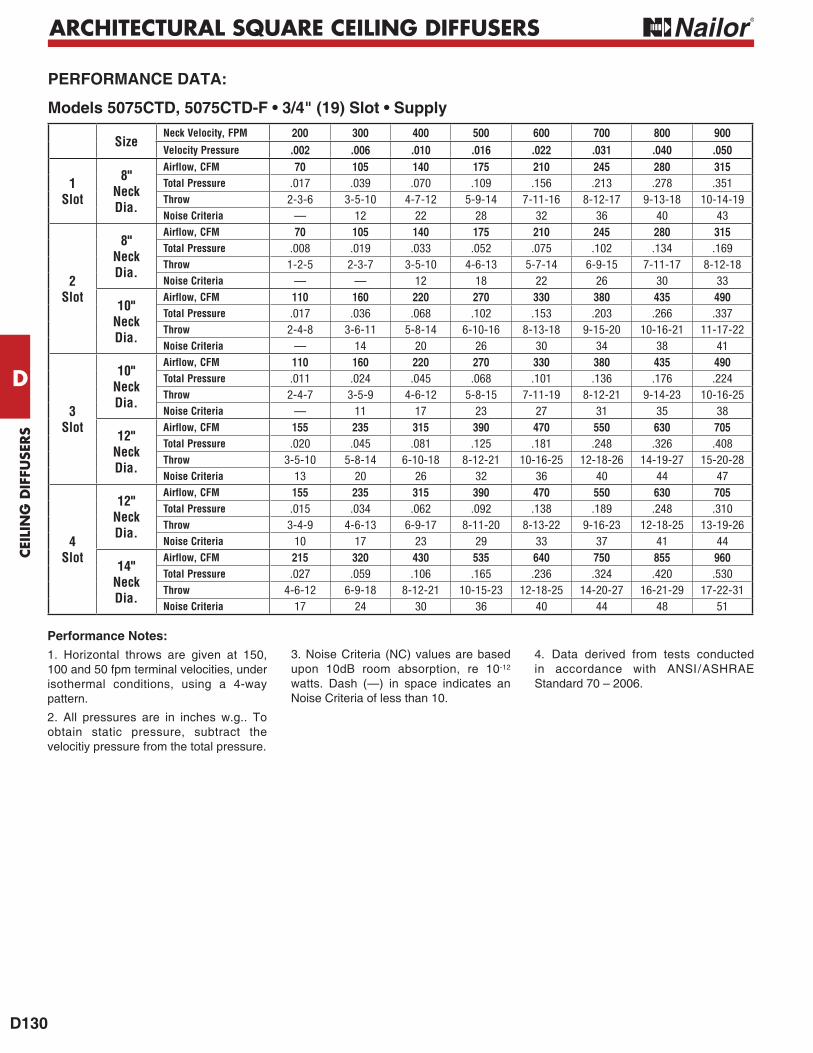
Models 5075CTD, 5075CTD-F • 3/4" (19) Slot • Supply
Performance Notes:1. Horizontal throws are given at 150, 100 and 50 fpm terminal velocities, under isothermal conditions, using a 4-way pattern.
2. All pressures are in inches w.g.. To obtain static pressure, subtract the velocitiy pressure from the total pressure.
3. Noise Criteria (NC) values are based upon 10dB room absorption, re 10-12
watts. Dash (—) in space indicates an Noise Criteria of less than 10.
4. Data derived from tests conducted in accordance with ANSI/ASHRAE Standard 70 – 2006.
SizeNeck Velocity, FPM 200 300 400 500 600 700 800 900Velocity Pressure .002 .006 .010 .016 .022 .031 .040 .050
1Slot
8"NeckDia.
Airflow, CFM 70 105 140 175 210 245 280 315Total Pressure .017 .039 .070 .109 .156 .213 .278 .351Throw 2-3-6 3-5-10 4-7-12 5-9-14 7-11-16 8-12-17 9-13-18 10-14-19Noise Criteria — 12 22 28 32 36 40 43
2Slot
8"NeckDia.
Airflow, CFM 70 105 140 175 210 245 280 315Total Pressure .008 .019 .033 .052 .075 .102 .134 .169Throw 1-2-5 2-3-7 3-5-10 4-6-13 5-7-14 6-9-15 7-11-17 8-12-18Noise Criteria — — 12 18 22 26 30 33
10"NeckDia.
Airflow, CFM 110 160 220 270 330 380 435 490Total Pressure .017 .036 .068 .102 .153 .203 .266 .337Throw 2-4-8 3-6-11 5-8-14 6-10-16 8-13-18 9-15-20 10-16-21 11-17-22Noise Criteria — 14 20 26 30 34 38 41
3Slot
10"NeckDia.
Airflow, CFM 110 160 220 270 330 380 435 490Total Pressure .011 .024 .045 .068 .101 .136 .176 .224Throw 2-4-7 3-5-9 4-6-12 5-8-15 7-11-19 8-12-21 9-14-23 10-16-25Noise Criteria — 11 17 23 27 31 35 38
12"NeckDia.
Airflow, CFM 155 235 315 390 470 550 630 705Total Pressure .020 .045 .081 .125 .181 .248 .326 .408Throw 3-5-10 5-8-14 6-10-18 8-12-21 10-16-25 12-18-26 14-19-27 15-20-28Noise Criteria 13 20 26 32 36 40 44 47
4Slot
12"NeckDia.
Airflow, CFM 155 235 315 390 470 550 630 705Total Pressure .015 .034 .062 .092 .138 .189 .248 .310Throw 3-4-9 4-6-13 6-9-17 8-11-20 8-13-22 9-16-23 12-18-25 13-19-26Noise Criteria 10 17 23 29 33 37 41 44
14"NeckDia.
Airflow, CFM 215 320 430 535 640 750 855 960Total Pressure .027 .059 .106 .165 .236 .324 .420 .530Throw 4-6-12 6-9-18 8-12-21 10-15-23 12-18-25 14-20-27 16-21-29 17-22-31Noise Criteria 17 24 30 36 40 44 48 51