SUBMITTAL DATA SHEET - UPGNET DATA SHEET SPLIT-SYSTEM ... High Static Mtr. and Drv. 357 385 15 30...
8
SUBMITTAL DATA SHEET SPLIT-SYSTEM EVAPORATOR BLOWERS 7.5, 10, 15 & 20 TONS MODELS: NH-07 thru -20, 2-PIPE NJ-10 thru -20, 4-PIPE Johnson Controls Unitary Products 506447-CSD-A-0209 JOB NAME: LOCATION: PURCHASER: ORDER NO: ENGINEER: SUBMITTED TO: FOR: REF: APPROVAL: CONSTRUCTION: SUBMITTED BY: DATE: UNIT DESIGNATION: SCHEDULE NO. MODEL NO. PRODUCT DATA Cooling Performance Total Capacity . . . . . . . . . . . . . . . ________ MBH Sensible Capacity . . . . . . . . . . . . ________ MBH Evaporator Pressure at Saturation. . . . . . . . . . . . . . . . . ________ PSIG Evaporator Temperature at Saturation. . . . . . . . . . . . . . . . . . . ________ °F Total Supply Air . . . . . . . . . . . . . . ________ CFM Temp. of air Entering Evaporator Coil . . . . . . . . . ___/___ °F DB/WB Heating Performance Refer to field-installed accessories on reverse side. Supply Air Blower Performance Total Supply Air . . . . . . . . . . . . . . ________ CFM Total Resistance External To Unit . . . . . . . . . . . . . . . . . . . ________ IWG Blower Speed. . . . . . . . . . . . . . . . ________ RPM Blower Output Requirement . . . . ________ BHP Motor Rating . . . . . . . . . . . . . . . . . ________ HP Power Input Requirement . . . . . . .________ KW Electrical Data Power Supply. . . . . . . . . . . . . . . . . . ___/___/___ Total Unit Ampacity . . . . . . . . . ________ AMPS Minimum Wire Size . . . . . . . . . . ________ AWG (Copper Conductors) Maximum Fuse Size Dual Element . . . . . . . . . . . . . ________ AMPS Unit Weight Total Operating Weight . . . . . . . ________ LBS (Including field-installed accessories) FEATURES • R-410A REFRIGERANT • POWDER PAINT FOR DURABILITY • INHERENTLY PROTECTED FAN MOTORS • SINGLE AND DUAL REFRIGERATION CIRCUITS (SINGLE ON NH AND DUAL ON NJ MODELS) • PROVISIONS FOR HOT GAS BYPASS • CSA APPROVAL • 2” AND 4” FILTER RACK (4” FILTERS FIELD SUPPLIED) • ELECTRIC HEAT (FIELD INSTALLED) • HOT WATER HEATING COILS (FIELD INSTALLED) • STEAM HEATING COILS (FIELD INSTALLED) • FACTORY SELECTABLE MOTOR AND DRIVE OPTIONS • ADJUSTABLE TXV’S • CAN BE APPLIED VERTICALLY OR HORIZONTALLY • SINGLE POINT POWER CONNECTION • ONE YEAR LIMITED PARTS WARRANTY ON COMPLETE UNIT • 5 YEAR LIMITED WARRANTY ON ELECTRIC HEATING ELEMENTS • DESIGNED TO OPERATE WITH COOLING ONLY UNITS OR HEAT PUMPS NH/NJ-20 INDOOR UNIT
Transcript of SUBMITTAL DATA SHEET - UPGNET DATA SHEET SPLIT-SYSTEM ... High Static Mtr. and Drv. 357 385 15 30...

SUBMITTAL DATA SHEETSPLIT-SYSTEM EVAPORATOR BLOWERS7.5, 10, 15 & 20 TONSMODELS: NH-07 thru -20, 2-PIPE
NJ-10 thru -20, 4-PIPE
Johnson Controls Unitary Products 506447-CSD-A-0209
JOB NAME: LOCATION:PURCHASER: ORDER NO:ENGINEER: SUBMITTED TO: FOR: REF: APPROVAL: CONSTRUCTION:SUBMITTED BY: DATE:UNIT DESIGNATION: SCHEDULE NO. MODEL NO.
PRODUCT DATACooling Performance
Total Capacity . . . . . . . . . . . . . . . ________ MBHSensible Capacity . . . . . . . . . . . . ________ MBHEvaporator Pressure at Saturation. . . . . . . . . . . . . . . . . ________ PSIGEvaporator Temperature at Saturation. . . . . . . . . . . . . . . . . . . ________ °FTotal Supply Air . . . . . . . . . . . . . . ________ CFMTemp. of air Entering Evaporator Coil . . . . . . . . . ___/___ °F DB/WB
Heating PerformanceRefer to field-installed accessories on reverse side.
Supply Air Blower PerformanceTotal Supply Air . . . . . . . . . . . . . . ________ CFMTotal Resistance External To Unit . . . . . . . . . . . . . . . . . . . ________ IWGBlower Speed. . . . . . . . . . . . . . . . ________ RPMBlower Output Requirement. . . . ________ BHPMotor Rating . . . . . . . . . . . . . . . . . ________ HPPower Input Requirement. . . . . . .________ KW
Electrical DataPower Supply. . . . . . . . . . . . . . . . . . ___/___/___Total Unit Ampacity . . . . . . . . . ________ AMPSMinimum Wire Size . . . . . . . . . . ________ AWG (Copper Conductors)Maximum Fuse Size Dual Element . . . . . . . . . . . . . ________ AMPS
Unit WeightTotal Operating Weight . . . . . . . ________ LBS (Including field-installed accessories)
FEATURES• R-410A REFRIGERANT• POWDER PAINT FOR DURABILITY• INHERENTLY PROTECTED FAN MOTORS• SINGLE AND DUAL REFRIGERATION CIRCUITS
(SINGLE ON NH AND DUAL ON NJ MODELS)• PROVISIONS FOR HOT GAS BYPASS• CSA APPROVAL• 2” AND 4” FILTER RACK (4” FILTERS FIELD SUPPLIED)• ELECTRIC HEAT (FIELD INSTALLED)• HOT WATER HEATING COILS (FIELD INSTALLED)• STEAM HEATING COILS (FIELD INSTALLED)• FACTORY SELECTABLE MOTOR AND DRIVE OPTIONS• ADJUSTABLE TXV’S• CAN BE APPLIED VERTICALLY OR HORIZONTALLY• SINGLE POINT POWER CONNECTION• ONE YEAR LIMITED PARTS WARRANTY ON COMPLETE UNIT• 5 YEAR LIMITED WARRANTY ON ELECTRIC HEATING ELEMENTS• DESIGNED TO OPERATE WITH COOLING ONLY UNITS OR HEAT PUMPS
NH/NJ-20 INDOOR UNIT
2 Johnson Controls Unitary Products
506447-CSD-A-0209
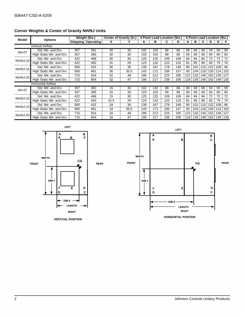
Corner Weights & Center of Gravity NH/NJ Units
Model Options Weight (lbs.) Center of Gravity (in.) 4 Point Load Location (lbs.) 6 Point Load Location (lbs.)Shipping Operating X Y A B C D A B C D E F
Vertical Airflow
NH-07 Std. Mtr. and Drv. 357 381 30 30 102 102 88 88 68 68 68 59 59 59High Static Mtr. and Drv. 357 385 30 30 103 103 89 89 69 69 69 60 60 60
NH/NJ-10 Std. Mtr. and Drv. 422 468 30 30 125 125 109 109 84 84 84 72 72 72High Static Mtr. and Drv. 422 492 31 29 123 132 123 115 81 85 89 83 79 76
NH/NJ-15 Std. Mtr. and Drv. 560 632 36 36 139 167 178 148 90 101 115 122 108 96High Static Mtr. and Drv. 560 661 36 35.5 143 172 189 157 93 104 118 130 114 102
NH/NJ-20 Std. Mtr. and Drv. 715 816 32 48 186 212 223 195 121 132 145 152 139 127High Static Mtr. and Drv. 715 854 32 47 190 217 238 208 124 135 148 162 148 136
Horizontal Airflow
NH-07 Std. Mtr. and Drv. 357 381 15 30 102 102 88 88 68 68 68 59 59 59High Static Mtr. and Drv. 357 385 15 30 103 103 89 89 69 69 69 60 60 60
NH/NJ-10 Std. Mtr. and Drv. 422 468 15 30 125 125 109 109 84 84 84 72 72 72High Static Mtr. and Drv. 422 492 15.5 29 123 132 123 115 81 85 89 83 79 76
NH/NJ-15 Std. Mtr. and Drv. 560 632 18 36 139 167 178 148 90 101 115 122 108 96High Static Mtr. and Drv. 560 661 18 35.5 143 172 189 157 93 104 118 130 114 102
NH/NJ-20 Std. Mtr. and Drv. 715 816 16 48 186 212 223 195 121 132 145 152 139 127High Static Mtr. and Drv. 715 854 16 47 190 217 238 208 124 135 148 162 148 136
CG
LENGTH
WIDTH
A
D
FRONT REAR
LEFT
RIGHT
DIM X
DIM Y
B
C
A B C
DEF
VERTICAL POSITION
CG
DIM X
DIM Y
LENGTH
WIDTH
A
D
FRONT REAR
LEFT
RIGHT
B
C
A B C
DEF
HORIZONTAL POSITION

Johnson Controls Unitary Products 3
506447-CSD-A-0209
UNIT DIMENSIONSNH-07/-10 & NJ-10
TOP VIEW
FRONT AND SIDE VIEW
*SEE UNITS PHYSICAL DATA TABLE FOR PIPING AND ELECTRICAL SIZE CONNECTIONS
Ø 1.38 KNOCKOUTELECTRIC HEAT CONNECTION
TOP VIEW - BLOWER OUTLETNH-07 INDOOR
TOP VIEW - BLOWER OUTLETNH/NJ-10 INDOOR
15.63 20.19
5.10
13.44
4.68
18.44
18.60 17.62
15.90
5.08
Ø 1.38 KNOCKOUTELECTRIC HEATCONNECTION
4.68
18.44
65.00
66.09
35.00
20.34
2.00
2.0053.44
56.16
FRONT VIEW - RETURN AIRNH-07 / -10 & NJ-10 INDOOR
30.009.06
2.595.09
Ø 1.09 KNOCKOUTPOWER ACCESS
Ø 0.88 KNOCKOUTCONTROLS ACCESS
FIELD PIPINGCONNECTIONS
DRAIN CONNECTION3/4 PVC PIPE CONNECTIONS
RIGHT SIDE VIEW - DRAIN PIPING/CONTROLS
6.541.42
9.8410.14
11.8712.23
7.436.445.544.16
SYSTEM 1*
SYSTEM 2
*SYSTEM 1 USED FOR 2-PIPE DIMENSIONS
4 Johnson Controls Unitary Products
506447-CSD-A-0209
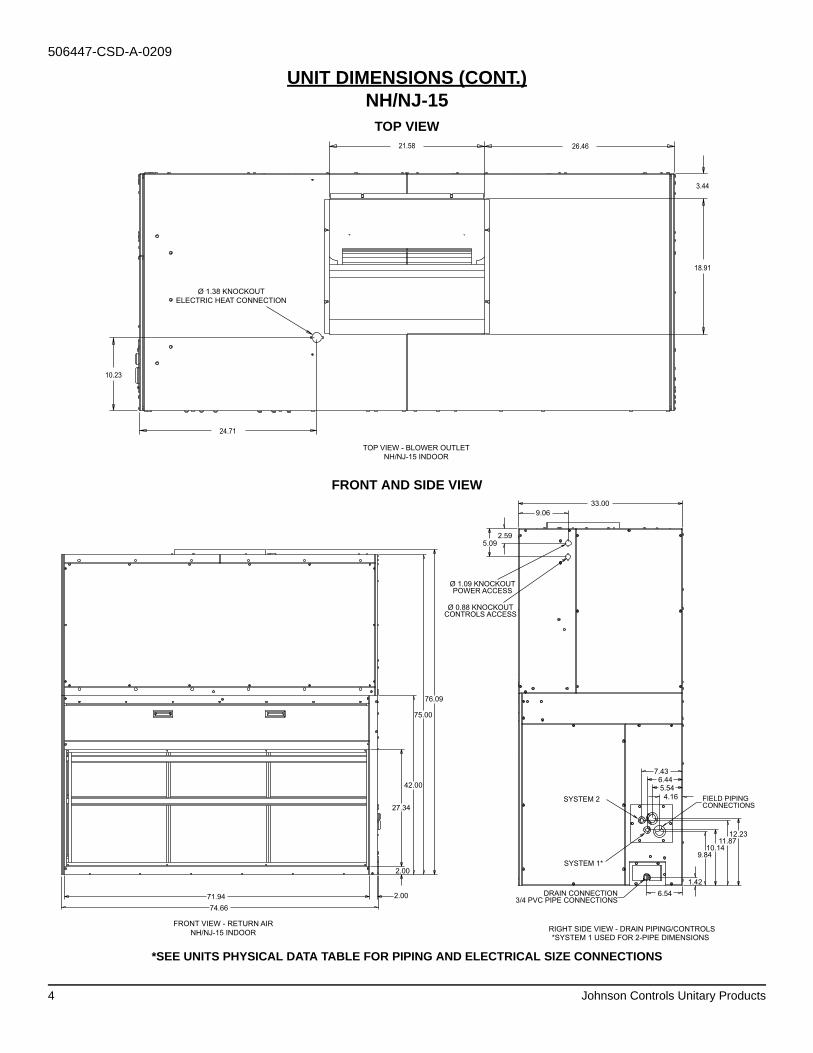
UNIT DIMENSIONS (CONT.)NH/NJ-15
TOP VIEW
FRONT AND SIDE VIEW
*SEE UNITS PHYSICAL DATA TABLE FOR PIPING AND ELECTRICAL SIZE CONNECTIONS
TOP VIEW - BLOWER OUTLETNH/NJ-15 INDOOR
Ø 1.38 KNOCKOUTELECTRIC HEAT CONNECTION
26.4621.58
3.44
18.91
24.71
10.23
76.09
75.00
42.00
27.34
2.00
2.00
FRONT VIEW - RETURN AIRNH/NJ-15 INDOOR
74.6671.94
33.009.06
2.595.09
Ø 1.09 KNOCKOUTPOWER ACCESS
Ø 0.88 KNOCKOUTCONTROLS ACCESS
FIELD PIPINGCONNECTIONS
DRAIN CONNECTION3/4 PVC PIPE CONNECTIONS
RIGHT SIDE VIEW - DRAIN PIPING/CONTROLS
6.541.42
9.8410.14
11.8712.23
7.436.445.544.16
SYSTEM 1*
SYSTEM 2
*SYSTEM 1 USED FOR 2-PIPE DIMENSIONS
Johnson Controls Unitary Products 5
506447-CSD-A-0209
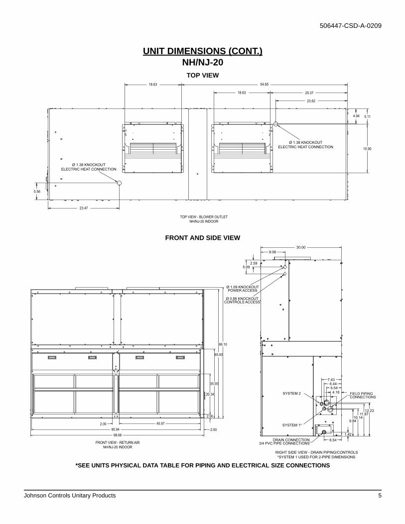
UNIT DIMENSIONS (CONT.)NH/NJ-20
TOP VIEW
FRONT AND SIDE VIEW
*SEE UNITS PHYSICAL DATA TABLE FOR PIPING AND ELECTRICAL SIZE CONNECTIONS
TOP VIEW - BLOWER OUTLETNH/NJ-20 INDOOR
18.63 54.65
18.63 25.37
23.62
23.47
5.56
Ø 1.38 KNOCKOUTELECTRIC HEAT CONNECTION
Ø 1.38 KNOCKOUTELECTRIC HEAT CONNECTION
4.94 5.11
15.90
FRONT VIEW - RETURN AIRNH/NJ-20 INDOOR
66.10
65.00
35.00
20.34
2.00
2.00
45.972.0095.94
98.66
30.009.06
2.595.09
Ø 1.09 KNOCKOUTPOWER ACCESS
Ø 0.88 KNOCKOUTCONTROLS ACCESS
FIELD PIPINGCONNECTIONS
DRAIN CONNECTION3/4 PVC PIPE CONNECTIONS
RIGHT SIDE VIEW - DRAIN PIPING/CONTROLS
6.541.42
9.8410.14
11.8712.23
7.436.445.544.16
SYSTEM 1*
SYSTEM 2
*SYSTEM 1 USED FOR 2-PIPE DIMENSIONS
6 Johnson Controls Unitary Products
506447-CSD-A-0209
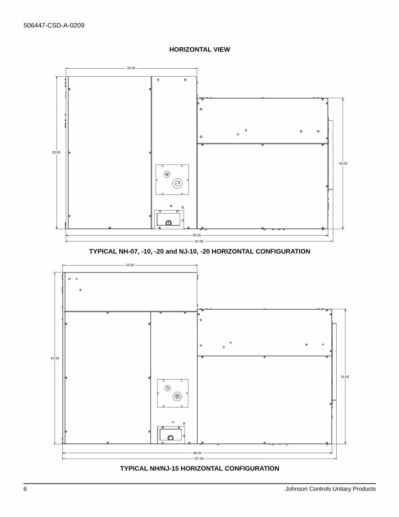
HORIZONTAL VIEW
TYPICAL NH-07, -10, -20 and NJ-10, -20 HORIZONTAL CONFIGURATION
[
TYPICAL NH/NJ-15 HORIZONTAL CONFIGURATION
35.00
30.00
30.00
61.09
60.00
66.00
67.09
33.00
42.00
33.00
Johnson Controls Unitary Products 7
506447-CSD-A-0209
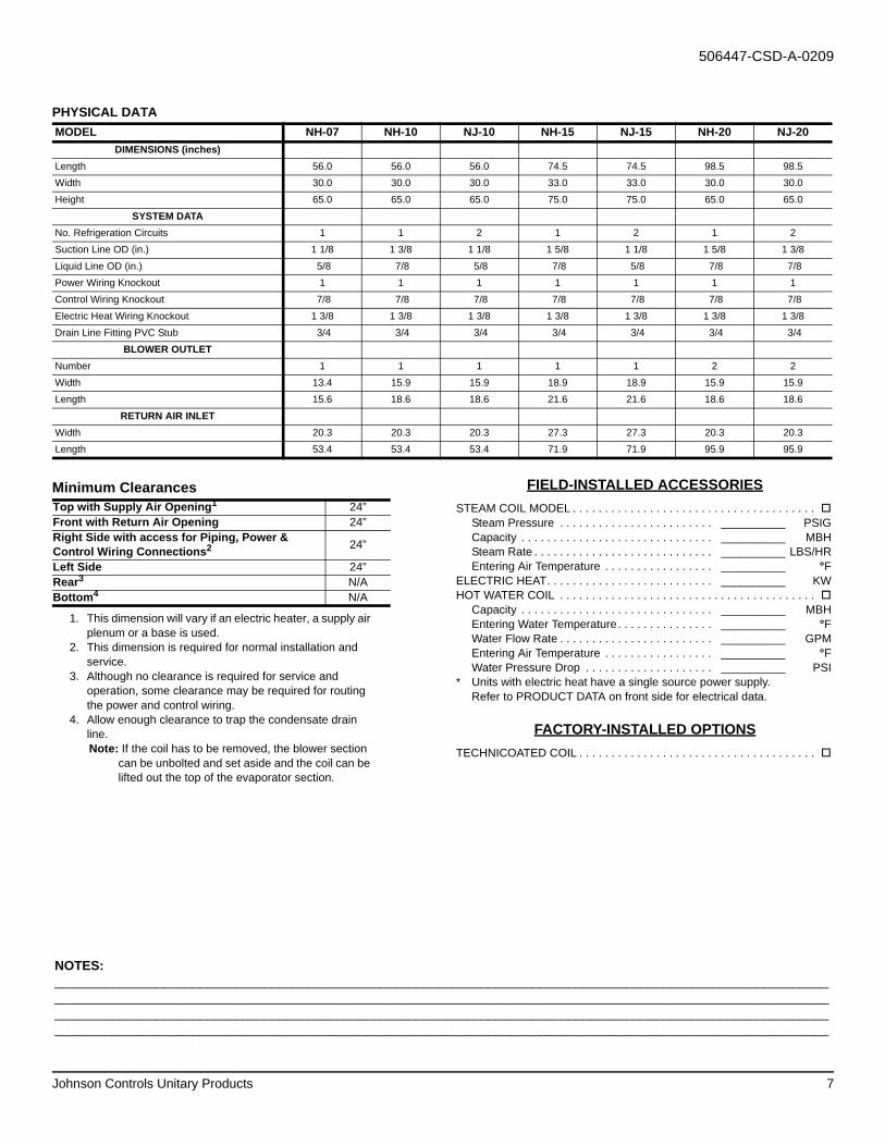
FIELD-INSTALLED ACCESSORIESSTEAM COIL MODEL . . . . . . . . . . . . . . . . . . . . . . . . . . . . . . . . . . . . . .
Steam Pressure . . . . . . . . . . . . . . . . . . . . . . . . __________ PSIGCapacity . . . . . . . . . . . . . . . . . . . . . . . . . . . . . . __________ MBHSteam Rate . . . . . . . . . . . . . . . . . . . . . . . . . . . . __________ LBS/HREntering Air Temperature . . . . . . . . . . . . . . . . . __________ °F
ELECTRIC HEAT. . . . . . . . . . . . . . . . . . . . . . . . . . __________ KWHOT WATER COIL . . . . . . . . . . . . . . . . . . . . . . . . . . . . . . . . . . . . . . . .
Capacity . . . . . . . . . . . . . . . . . . . . . . . . . . . . . . __________ MBHEntering Water Temperature. . . . . . . . . . . . . . . __________ °FWater Flow Rate . . . . . . . . . . . . . . . . . . . . . . . . __________ GPMEntering Air Temperature . . . . . . . . . . . . . . . . . __________ °FWater Pressure Drop . . . . . . . . . . . . . . . . . . . . __________ PSI
* Units with electric heat have a single source power supply.Refer to PRODUCT DATA on front side for electrical data.
FACTORY-INSTALLED OPTIONSTECHNICOATED COIL . . . . . . . . . . . . . . . . . . . . . . . . . . . . . . . . . . . . .
PHYSICAL DATAMODEL NH-07 NH-10 NJ-10 NH-15 NJ-15 NH-20 NJ-20
DIMENSIONS (inches)Length 56.0 56.0 56.0 74.5 74.5 98.5 98.5Width 30.0 30.0 30.0 33.0 33.0 30.0 30.0Height 65.0 65.0 65.0 75.0 75.0 65.0 65.0
SYSTEM DATANo. Refrigeration Circuits 1 1 2 1 2 1 2Suction Line OD (in.) 1 1/8 1 3/8 1 1/8 1 5/8 1 1/8 1 5/8 1 3/8Liquid Line OD (in.) 5/8 7/8 5/8 7/8 5/8 7/8 7/8Power Wiring Knockout 1 1 1 1 1 1 1Control Wiring Knockout 7/8 7/8 7/8 7/8 7/8 7/8 7/8Electric Heat Wiring Knockout 1 3/8 1 3/8 1 3/8 1 3/8 1 3/8 1 3/8 1 3/8Drain Line Fitting PVC Stub 3/4 3/4 3/4 3/4 3/4 3/4 3/4
BLOWER OUTLETNumber 1 1 1 1 1 2 2Width 13.4 15.9 15.9 18.9 18.9 15.9 15.9Length 15.6 18.6 18.6 21.6 21.6 18.6 18.6
RETURN AIR INLETWidth 20.3 20.3 20.3 27.3 27.3 20.3 20.3Length 53.4 53.4 53.4 71.9 71.9 95.9 95.9
Minimum ClearancesTop with Supply Air Opening1
1. This dimension will vary if an electric heater, a supply air plenum or a base is used.
24”Front with Return Air Opening 24”Right Side with access for Piping, Power & Control Wiring Connections2
2. This dimension is required for normal installation and service.
24”
Left Side 24”Rear3
3. Although no clearance is required for service and operation, some clearance may be required for routing the power and control wiring.
N/ABottom4
4. Allow enough clearance to trap the condensate drain line.Note: If the coil has to be removed, the blower section
can be unbolted and set aside and the coil can be lifted out the top of the evaporator section.
N/A
NOTES: ____________________________________________________________________________________________________________________________________________________________________________________________________________________________________________________________________________________________________________________________________________________________________________________________________________________________________________

Subject to change without notice. Printed in U.S.A. 506447-CSD-A-0209Copyright © 2009 by Johnson Controls, Inc. All rights reserved. Supersedes: Nothing
Johnson Controls Unitary Products5005 York Drive
Norman, OK 73069