Submittal 100kVA Power Distribution Unit 480V Input / 208 ... · The Phase Shift transformer shall...
20
Submittal 100kVA Power Distribution Unit 480V Input / 208/120V Output Submitted to: Paul Egger Company: Microsoft Corporation DATE: May 1, 2001
Transcript of Submittal 100kVA Power Distribution Unit 480V Input / 208 ... · The Phase Shift transformer shall...
Submittal 100kVA Power Distribution Unit 480V Input / 208/120V Output
Submitted to: Paul Egger Company: Microsoft Corporation DATE: May 1, 2001

CONTENTS
Section I: Bill of Materials…………... Proposed System Weights and Dimensions Section II: PDU Technical Description… Description of PDU Section III: System Installation Data…. System Drawings
SECTION I
Bill of Materials
Includes: • System Descriptions • System Dimensions • System Weights

BILL OF MATERIALS • Power Distribution Module Cabinet Model: PDM4 • Cabinet Physical Dimensions: 43.5"W x 34"D x 69"H ~ Top Entry • Main Input Breaker: 150 Amps @ 480 VAC, 25 KAIC • Qty (4) 42 pole position GE panelboards • Qty (4) 225 Amp Secondary Main Circuit Breakers, 10KAIC • System kVA: 100 with PS2 transformer • Input Voltage: 480 VAC 3 phase, 3 wire + grd @ 60 Hz. • Output Voltage: 120/208 VAC 3 phase, 4 wire + grd @ 60 Hz. • Unit Monitoring Level: Focus Level III w/3rd Party Protocol • Manual Restart • Lightning Arrestor / Surge Suppressor • Removable side panel • Qty (168) 1-Pole, 20 Amp distribution breakers
OPTIONAL ITEMS
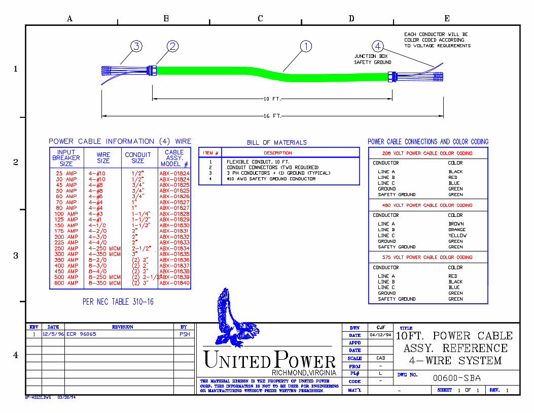
• Optional Seismic Angle Brackets • Top Hat Option (For 4 panel board systems with one side car) • Power Junction Box & 10' Power Cable
SECTION II
PDU Technical Description
Includes:
• System Technical Description as reference only. Not necessary for installation.

100kVA POWER DISTRIBUTION UNIT WITH PHASE SHIFT TRANSFORMER
MICROSOFT PROJECT SPECIFICATION
1.0 GENERAL
The following technical specification describes the requirements of the power conditioning/distribution module for distribution of computer grade power to the data processing equipment and other critical loads. The system shall be capable of feeding multiple loads with similar harmonic characteristics and canceling the harmonics of those loads utilizing the shifted outputs of the transformer. The system shall be known as a Power Distribution Module (PDM).
2.0 STANDARDS
The PDM shall be designed and manufactured to the following standards:
2.1. Underwriters Laboratory (UL) Section 478 2.2. National Electric Code, 1996 (NEC) 2.3. National Electrical Manufacturers Association (NEMA) 2.4. Occupational Safety and Health Act (OSHA) 2.5. American National Standards Institute (ANSI) 2.6. National Fire Protection Association (NFPA) 2.7. Federal Information Processing Standards (FIPS)
3.0 ENVIRONMENTAL REQUIREMENTS
The PDM shall be designed for operation in the following conditions:
3.1. Temperature 10oC - 40oC 3.2. Humidity 0-95% RH 3.3. Altitude 0-8500 feet 3.4. Audible Noise 43 db maximum
4.0 ELECTRICAL REQUIREMENTS
4.1. The PDM shall have a full load continuous capacity of 100 KVA. 4.2. The input voltage to the PDM shall be 480 VAC, three (3) phase, three (3) wire plus
ground @ 60 Hz. 4.3. The output voltage from the PDM shall be 208/120 VAC wye, three (3) phase, four (4)
wire plus ground @ 60 Hz.

5.0 INPUT POWER JUNCTION BOX AND INPUT POWER CABLE
5.1. The PDM system shall include a watertight input power junction box for placement under the computer room raised floor.
5.2. The input power junction box shall not exceed 6 inches height to allow proper movement
of conditioned air in the plenum created by the raised floor system. 5.3. The input power junction box shall contain four (4) terminal blocks for termination of the
incoming phase conductors and the ground conductor. It shall be the electrical contractor's responsibility to make all terminations in the system's input power junction box. No low voltage control circuitry shall be allowed in this high voltage junction box due to safety purposes.
5.4. A low voltage control junction box shall not be included on this equipment. All Remote
Emergency Power Off, HVAC interlocks, building alarm circuitry, and other control wiring shall be terminated onto a circuit board which is an integral component within the PDM system itself. This is a strict requirement of the specification due to the criticality of proper air movement under the raised floor.
This circuit card shall contain, as a minimum, the following:
a. Three (3) Remote Emergency Power Off interconnect positions.
b. HVAC Interlock Positions including:
1. One (1) normally open/maintained interconnect. 2. One (1) normally closed/maintained interconnect. 3. One (1) normally open/momentary interconnect. 4. One (1) normally closed/momentary interconnect.
5.5. The input power junction box shall be clearly labeled "Danger High Voltage" for safety
purposes. 5.6. The PDM system shall include a flexible input power cable to interconnect the input
power junction box to the PDM system main circuit breaker as described in section 6.2 of this specification.
6.0 PDM SYSTEM DESCRIPTION
6.1. Cabinet Construction
6.1.1. The PDM cabinet enclosure shall be designed for placement on the computer room raised floor. The system shall be aesthetically pleasing and shall not exceed 43.5"W, 34"D, and 69"H.

6.1.2. The cabinet enclosure shall be mobile and contain four (4) 360o swivel casters and four (4) leveling feet for stability purposes.
6.1.3. The cabinet enclosure shall be a single bay vertical cabinet using natural
convection for cooling purposes. Forced air (fan) cooling is expressly forbidden via this specification.
6.1.4. The PDM enclosure shall be designed to allow all routine service, including
compensation tap changes, to be made requiring FRONT ACCESS ONLY. This feature is a strict requirement of this specification, due to the valuable nature of computer room raised floor space on this project.
6.1.5. The PDM cabinet enclosure shall be designed to accept one distribution
expansion cabinet containing an additional 84 circuit breaker pole positions each. The distribution expansion cabinets shall not exceed 9 1/2 inches wide each and shall become an integral part of the PDM system.
6.1.6. The PDM cabinet enclosure shall be painted pearl white to complement the data
processing equipment in this facility. The paint shall be a textured semi-gloss enamel to match the EDP equipment painted surfaces.
6.1.7. Each PDM cabinet enclosure shall be provided with two mounting angles for
seismic environments.
6.1.8. Each PDM cabinet enclosure shall be provided with solid tops for use in top entry situations. The solid top allows the customer to drill custom knockouts specific to the cables used in their application.
6.2. Input Main Circuit Breaker
6.2.1. The PDM shall include an input main circuit breaker to provide both system
protection and a means of disconnecting power from the system. 6.2.2. The system's input main circuit breaker shall be a line voltage rated, 3-pole
thermal magnetic molded case circuit breaker sized for 125% of the PDM full load current rating.
6.2.3. The system's input main circuit breaker shall contain a 24 VDC shunt trip
mechanism which shall be interfaced to the local Emergency Power Off (EPO) pushbutton on the PDM as well as all remote EPO pushbutton stations at each computer room exit.
6.2.4. The system's input main circuit breaker shall have an interrupting rating of 25,000
AIC @ 480 VAC.
6.2.5. The system shall be equipped with an undervoltage sensing circuit. In the event of a complete phase loss or an abnormally low input voltage condition, the circuit breaker will trip thus requiring the system’s main input circuit breaker to be manually restarted to resume data processing operations.

6.2.6. The major insulation of magnetic components shall be protected against forms of high energy surges such as those associated with lightning discharges. A protective capacitor rated 650V shall be used to reduce the rate of rise of surge voltages and shall provide the necessary protection to the turn insulation of the internal magnetic components. The proposed system shall include a factory-installed lightning arrestor that is positioned on the line side of the system. The lightning arrestor shall have the following performance characteristics:
Ø Arrestor Rating 650 VAC Ø Maximum FOW Sparkover 3200 Volts Ø Discharge Voltage 2.2 KV @ 1500 Amps Ø Current Wave 8 X 20 Amps Ø Discharge Capabilities 10,000 Amps
The proposed system shall also include a factory-installed surge suppressor which is a secondary protective capacitor specifically designed to be used in tandem with the lightning arrestor. This line side surge suppressor shall provide the user with the following protective characteristics:
Ø Suppressor Rating 650 VAC Ø Discharge Voltage 2.6 KV @ 1500 Amps Ø Current Wave 8 X 20 microsecond Ø Discharge Capabilities 40,000 Amps
6.3. High Isolation Transformer
6.3.1. The PDM shall contain a high isolation electrostatically shielded Phase Shift
transformer capable of feeding multiple outputs with similar harmonic characteristics and substantially reducing the load generated harmonics. The manufacturer shall supply to the engineer at least ten days prior to the bid date complete documentation of the canceling capabilities of the proposed transformer. The Phase Shift transformer shall K-13 rated to handle the triplen harmonics generated by the load. The Phase shift transformer shall also provide for both voltage step-down and isolation purposes. The transformer shall be constructed using all copper windings and shall employ six (6), 2 1/2% full load compensation taps (two [2] above and four [4] below nominal).

6.3.2. The PDM high isolation transformer shall have the following electrical and
construction characteristics:
Rated KVA 100 KVA Primary Voltage 480 VAC, 3 PH, 3W + Ground Secondary Voltage 208/120 VAC, 3 PH, 4W + Ground Input/Output Frequency 60 Hz Percent Impedance 3.5% Percent Reactance 3.0% Harmonic Distortion 1% mx. Full Load Efficiency 97.5% Insulation Class Class "H" Temperature Rise 150oC Audible Noise 43 db
6.3.3. The neutral of the high isolation transformer shall be rated 1.732 times the system
full load amps rating. This is a strict requirement of the specification due to the anticipated high nonlinear loads associated with this project.
6.3.4. The transformer shall contain two (2) overload protection devices to monitor core
temperature. The first thermal device shall be calibrated at 190oC. The second thermal device shall be calibrated at 220oC. In the event of a 220oC core temperature condition, the thermal overload protection device shall close a set of contacts and initiate an automatic shutdown event.
6.3.5. The transformer shall be cooled by natural convection means as detailed in
section 6.1.3 of this technical specification.
6.4. Output Distribution Panelboards
6.4.1. The PDM shall contain four (4) GE, 42-pole, 225 amp, 240V, three (3) phase distribution panelboards with a short circuit rating of 10,000 AIC.
6.4.2. Each distribution panelboard shall employ copper busbars and shall be capable of
accepting 1-pole, 2-pole, and 3-pole circuit breakers rated up to 100 amps. 6.4.3. Each distribution panelboard shall be capable of accepting bolt-on branch circuit
breakers into the panelboard interior. 6.4.4. Each distribution panelboard shall feature a 42-position neutral bus assembly and
a 42-position ground bus kit to provide sufficient output ground and neutral termination space. The ground and neutral bus kits shall be mounted parallel to its distribution panelboard to facilitate optimum spacing for ease of installation and expansion purposes. Systems with bus kits mounted below the distribution panelboards are expressly forbidden via this specification.
6.4.5. Each neutral bus kit associated with each 42-pole distribution panelboard shall be

fed by two (2) 1/0 75oC THHN/THWN copper conductors. This will provide 450 amps of conductor to each neutral bus kit to accommodate the anticipated high nonlinear loads associated with this project.
6.4.6. Each 42-pole distribution panelboard shall be protected by a 225 amp, 240V, 3-
pole main circuit breaker protective device.
6.4.7. The PDM shall include a computer grade, single point ground in accordance with computer manufacturer’s recommendations and the requirements of the NEC.
6.5. System Monitor Panel
6.5.1. The PDM shall employ a microprocessor based monitor panel and shall monitor both power and environmental points within the computer room.
6.5.2. The monitoring panel shall become an integral part of the PDM and shall indicate
the following system information:
a. KVA value of the system b. Module number
6.5.3. The monitoring panel shall employ an audible alarm to annunciate any fault
condition. 6.5.4. The PDM shall continuously monitor the core temperature of the main isolation
transformer. The transformer shall be equipped with two (2) thermal sensors (see section 6.3.4), one (1) to announce a "High Temperature" condition and the other to automatically shut down the PDM upon a hazardous temperature condition (220oC).
6.5.5. The monitoring panel shall contain a yellow "HIGH TEMP" warning illuminated
pushbutton assembly to visually indicate a first stage high temperature condition. Upon this condition, the audible alarm will sound. Silencing the alarm shall be accomplished by pressing the yellow "HIGH TEMP" pushbutton, thus acknowledging the condition itself.
6.5.6. The PDM monitoring panel shall contain a fully-guarded, red illuminated
Emergency Power Off pushbutton assembly. This control circuit shall be interconnected to the 24 VDC shunt trip mechanism (see section 6.2.3) and shall allow the user to completely remove the PDM from the line.
6.5.7. The PDM shall contain a building interface board which is to be located on the
front and bottom of the PDM near the cable landing area. This board shall allow the local installing electrical contractor to interconnect remote emergency power off pushbutton stations to the EPO control circuit as described in section 6.7.6 of this specification.
6.5.8. The monitor panel shall also contain an eighty (80) character LCD display to
display both alarm and corrective action instructions upon an alarm condition. 6.5.9. The monitor panel shall feature a custom keypad to allow the user to custom
program the system's alarm names, corrective action messages, time, date, and other parameters into the system's central processing unit.
6.5.10. The monitor panel shall have programmable scan and hold modes to allow the
user to either continuously scan all monitored parameters or fix onto a given eighty (80) character display of their choice.
6.5.11. The monitor panel shall continuously monitor the PDM for the following alarm
conditions:
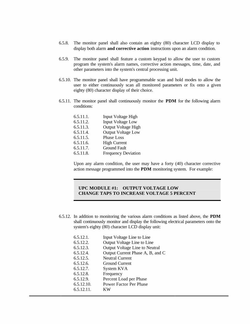
6.5.11.1. Input Voltage High 6.5.11.2. Input Voltage Low 6.5.11.3. Output Voltage High 6.5.11.4. Output Voltage Low 6.5.11.5. Phase Loss 6.5.11.6. High Current 6.5.11.7. Ground Fault 6.5.11.8. Frequency Deviation Upon any alarm condition, the user may have a forty (40) character corrective action message programmed into the PDM monitoring system. For example:
6.5.12. In addition to monitoring the various alarm conditions as listed above, the PDM shall continuously monitor and display the following electrical parameters onto the system's eighty (80) character LCD display unit:
6.5.12.1. Input Voltage Line to Line 6.5.12.2. Output Voltage Line to Line 6.5.12.3. Output Voltage Line to Neutral 6.5.12.4. Output Current Phase A, B, and C 6.5.12.5. Neutral Current 6.5.12.6. Ground Current 6.5.12.7. System KVA 6.5.12.8. Frequency 6.5.12.9. Percent Load per Phase 6.5.12.10. Power Factor Per Phase 6.5.12.11. KW
UPC MODULE #1: OUTPUT VOLTAGE LOW CHANGE TAPS TO INCREASE VOLTAGE 5 PERCENT

6.5.12.12. KWH Consumption 6.5.12.13. Peak Demand 6.5.12.14. Phase Rotation 6.5.12.15. Time of Day 6.5.12.16. Date
6.5.13. In addition to the above monitoring features, the system shall have the ability to
accept either normally open or normally closed contacts from up to six (6) building interface points. The PDM monitor panel shall provide the user the name of the unit as well as the ability to assign a twenty (20) character name of the building alarm point. The PDM monitor panel shall also allow the user to program a corrective action message of up to forty (40) characters into the system. For example:
6.5.14. Each PDM shall be provided with Third Party Protocol package for
communication purposes. 7.0 SYSTEM WARRANTY
The PDM manufacturer shall guarantee the entire system against defective material and workmanship for a period of one (1) year following delivery from the manufacturer. Maintenance contracts are available to extend the original equipment warranty while providing two (2) preventive maintenance service calls per year to verify proper equipment performance.
8.0 EXECUTION
Factory start-up and user training, preventive maintenance service, and full service for the above specified system shall be included upon request. The manufacturer shall nationally employ service organizations of factory-trained field service personnel dedicated to the start-up, maintenance, and repair of the manufacturer’s power equipment.
The manufacturer shall maintain (24 hours per day, 365 days per year) an answering service to facilitate in providing technical support and emergency service dispatching.
8.1 INSTALLATION, INSPECTION, AND FACTORY AUTHORIZED STARTUP
Installation and start up shall included the following:
• Ensure removal of temporary shipping bracing. • Verify all electrical connections for tightness as specified.
UPC MODULE #1: AC #2 DASD AREA DOWN CALL JOE AT 1-800-555-1212 FOR SERVICE

• Review the field assembly and connection of components. • Inspect accessible components for cleanliness, for mechanical and electrical integrity, and for
evidence of damage or deterioration. • Pretest and adjust all transfer, monitoring and/or control parameters as required. • Correct all deficiencies before proceeding with tests. Correct deficiencies identified by tests
and retests. • If applicable, adjust transformer taps to provide optimum voltage conditions at utilization
equipment throughout the normal operation cycle of the facility. • Record circuit monitors set-ups, if applicable.
8.2 TRAINING
Concurrent with factory authorized system startup the manufacturer’s field service engineer shall train the owner’s operating personnel in the proper operation of the system. Training shall last a minimum of two hours and shall include:
• Safety precautions • Features and construction of project equipment • Voltage adjustment procedures, if applicable • Routine inspection, cleaning and test procedures • Interpretation of reading of indicating and alarm
END OF SPECIFICATION FOR EQUIPMENT

SECTION III
System Drawings
Includes:
• System drawings for evaluation and technical information.