SUBMISSION OF AMERICAN AIRLINES, INC. TO THE NATIONAL TRANSPORTATION SAFETY BOARD · TO THE...
67
SUBMISSION OF AMERICAN AIRLINES, INC. TO THE NATIONAL TRANSPORTATION SAFETY BOARD ACCIDENT INVOLVING AMERICAN AIRLINES FLIGHT 587 AT BELLE HARBOR, NEW YORK NOVEMBER 12, 2001 DCA02MA001 March 1, 2004
Transcript of SUBMISSION OF AMERICAN AIRLINES, INC. TO THE NATIONAL TRANSPORTATION SAFETY BOARD · TO THE...
SUBMISSION OF AMERICAN AIRLINES, INC. TO THE NATIONAL TRANSPORTATION
SAFETY BOARD
ACCIDENT INVOLVING AMERICAN AIRLINES FLIGHT 587 AT BELLE HARBOR, NEW YORK
NOVEMBER 12, 2001
DCA02MA001
March 1, 2004

TABLE OF CONTENTS
Page
I. EXECUTIVE SUMMARY .......................................................................................... 1
II. ORGANIZATION OF SUBMISSION......................................................................... 5
III. FACTUAL ANALYSIS ............................................................................................... 6
A. Flight Control Design and Rudder Limiting Methodology .................................... 6
1. Rudder Ratio Changer Systems ........................................................................ 7
2. Hinge Moment Limiting (or “Blowdown”) Systems........................................ 7
3. Mechanical Rudder Travel Limiter Systems .................................................... 8
B. The A300-600/A310 Rudder Control System ........................................................ 9
1. The Sensitivity of the A300-600/A310 Rudder Control System...................... 9
2. The Ability to Modulate A300-600 Rudder Pedal Inputs as Airspeed Increases...................................................................................... 11
3. Inadvertent Suppression of the Yaw Damper in the A300-600/A310............ 16
C. Aircraft Pilot Coupling (APC) and Pilot Involved Oscillation............................. 20
1. The Definition of APC and Pilot Involved Oscillation................................... 20
2. Most Severe, Adverse APC Events Are Not Caused by Pilots....................... 21
3. The Role of Adverse APC/Pilot Involved Oscillation in Flight 587 .............. 23
4. Rate Saturation as a Contributing Factor ........................................................ 25
5. Consideration by Airbus of the Human Factors Impact of the Transition from the A300B2/B4 to the A300-600/A310................................ 26
6. The BEA’s Comments to Dr. Hess’s Report .................................................. 29
D. Airbus A300-600 and A310 High Load Events.................................................... 30
1. Airbus’s Knowledge of Other A300-600/A310 High Load Events................ 30
a. Interflug (Event H on Exhibit 7Q) ...................................................... 32
b. American Flight 903 (Event B on Exhibit 7Q)................................... 32
i
c. Air France Flight 825 (Event J on Exhibit 7Q)................................... 33
2. Airbus’s Awareness of the RTLU Design Limitations................................... 34
3. Lack of Airbus Guidance about the Changes in the Rudder Control System from the A300B2/B4 to the A300-600/A310 ....................... 34
4. Airbus’s Internal Decision Making Process ................................................... 35
5. The Need for Ground Training for Adverse APC Susceptible Aircraft and Specific Training for A300-600/A310 Pilots ............................. 36
E. Certification .......................................................................................................... 38
1. A300-600 Compliance with Advisory Circulars 25-7A and 25-7 or their Substantive Equivalents ...................................................... 38
2. Need for Additional Work to Evaluate APC and Human Factors Considerations................................................................................................. 40
F. Pilot Awareness and Perception of Maneuvering Speed and Rudder Limiting Protection .................................................................................. 42
1. Content of Airbus Manuals before Flight 587 about Rudder Reversals......... 42
2. Content of Airbus Manuals before Flight 587 about Rudder Pedal Force Feel Gradient......................................................................................... 44
G. American’s Pilot Training Program...................................................................... 45
1. The Background of American’s Advanced Aircraft Maneuvering Program (AAMP) ..................................................................... 46
2. The August 1997 AAMP Letter and American’s Response........................... 47
3. The Industry Airplane Upset Recovery Training Aid..................................... 50
4. One Captain’s Observation of Flight 587’s First Officer ............................... 50
5. Management Pilots’ Critique of AAMP ......................................................... 51
H. The Effect of Wake Turbulence............................................................................ 52
IV. SUMMARY OF ANALYSIS..................................................................................... 53
V. PROBABLE CAUSE AND CONTRIBUTING FACTORS...................................... 56
VI. SUGGESTED SAFETY RECOMMENDATIONS ................................................... 57
ii
A. The FAA should review the A310/A600-300 flight control system flying qualities and handling qualities evaluations for design and certification ............. 57
B. The FAA should review the certification process................................................. 57
C. Operators should make pilots aware of adverse aircraft pilot coupling (APC) /pilot involved oscillations and the potential for rudder reversals........................ 59
D. Airbus should develop specific pilot training for operators of the A300-600/A310 .......................................................................................... 59
E. The FAA should require manufacturers to develop FAA-approved guidance on upset recovery training ..................................................................... 60
F. The FAA should clarify the definition of maneuvering speed ............................. 61
G. The FAA should determine why system safety failures occurred ........................ 61
iii

I. EXECUTIVE SUMMARY
The sudden, catastrophic failure and separation of the vertical stabilizer and rudder on American Airlines Flight 587 stunned the world aviation community. An in-flight structural breakup in such unthreatening conditions had never occurred before on a modern transport category commercial aircraft. Unfortunately, this accident never should have happened and could have been prevented if Airbus had disclosed to American, the FAA, or the Safety Board what it knew about the propensity of the flight control system on the A300-600 to allow hazardous rudder control inputs that could cause structural damage to the vertical stabilizer.
Before this accident, virtually all pilots and operators of transport category aircraft worldwide were unaware that sequential, opposite rudder deflections (“rudder reversals”) could generate forces exceeding the airframe’s structural capabilities. In fact, this danger even applied at operating speeds below design maneuvering speed (the maximum airspeed at which full control surface deflections were thought not to cause structural damage, also referred to as “Va”). Instead, pilots and operators believed that the rudder limiting systems designed and installed by the manufacturers would prevent airframe damage from occurring within the design maneuvering speed envelope.
This investigation, however, has revealed that the Airbus A300-600 series aircraft and their close “cousin,” the A310, use a combination of flight control system features unlike those of any other transport category aircraft. These features make the A300-600/A310 aircraft acutely susceptible to a phenomenon known as adverse aircraft pilot coupling (APC), which can result in the generation of very large, rapid yawing moments resulting in high lateral load forces and ultimately structural failure.
An adverse APC event is an unwanted, unexpected, and anomalous interaction between the airplane and pilot causing the airplane motion to become out of phase with the pilot’s control inputs. The most commonly known form of adverse APC involves unintended, sustained “oscillatory” motions of the aircraft. These events are also known as pilot involved oscillations. Adverse APC has sometimes been referred to in the aviation community as “pilot induced oscillation.” The choice of this term, however, is unfortunate because it conveys a misunderstanding that the pilots are at fault. In fact, as explained below, pilots are not to blame for adverse APC.
At the request of the Safety Board, Dr. Ronald A. Hess wrote a detailed report for the Human Performance Group on the relationship between adverse APC and Flight 587. Dr. Hess is an APC expert, and he was a member of the Committee established by the National Research Council (the “NRC Committee”) in the mid-1990s to study APC and related safety of flight issues. Like the NRC Committee, Dr. Hess explains the misunderstandings caused by imprecise terminology and clarifies at the beginning of his report that adverse APC almost invariably is caused by a deficient flight control system characteristic, rather than by the pilot.
1
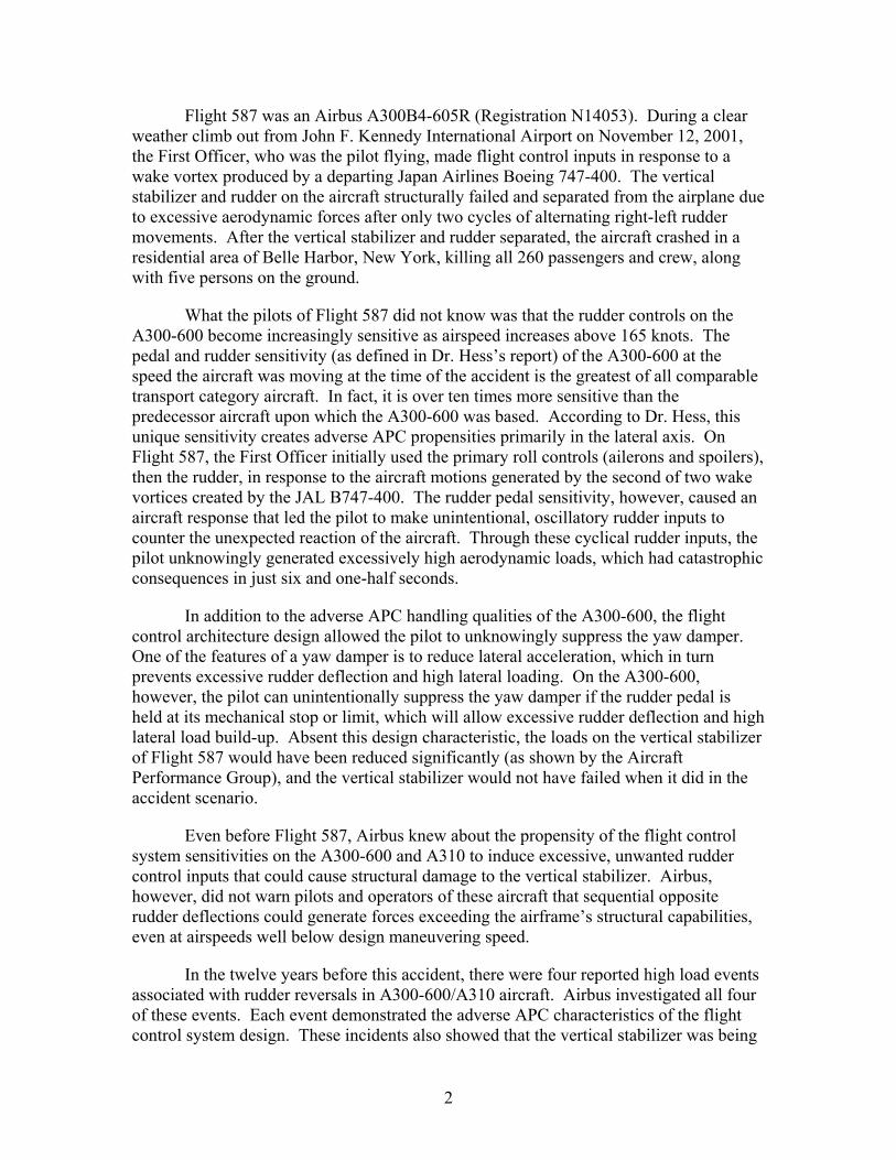
Flight 587 was an Airbus A300B4-605R (Registration N14053). During a clear weather climb out from John F. Kennedy International Airport on November 12, 2001, the First Officer, who was the pilot flying, made flight control inputs in response to a wake vortex produced by a departing Japan Airlines Boeing 747-400. The vertical stabilizer and rudder on the aircraft structurally failed and separated from the airplane due to excessive aerodynamic forces after only two cycles of alternating right-left rudder movements. After the vertical stabilizer and rudder separated, the aircraft crashed in a residential area of Belle Harbor, New York, killing all 260 passengers and crew, along with five persons on the ground.
What the pilots of Flight 587 did not know was that the rudder controls on the A300-600 become increasingly sensitive as airspeed increases above 165 knots. The pedal and rudder sensitivity (as defined in Dr. Hess’s report) of the A300-600 at the speed the aircraft was moving at the time of the accident is the greatest of all comparable transport category aircraft. In fact, it is over ten times more sensitive than the predecessor aircraft upon which the A300-600 was based. According to Dr. Hess, this unique sensitivity creates adverse APC propensities primarily in the lateral axis. On Flight 587, the First Officer initially used the primary roll controls (ailerons and spoilers), then the rudder, in response to the aircraft motions generated by the second of two wake vortices created by the JAL B747-400. The rudder pedal sensitivity, however, caused an aircraft response that led the pilot to make unintentional, oscillatory rudder inputs to counter the unexpected reaction of the aircraft. Through these cyclical rudder inputs, the pilot unknowingly generated excessively high aerodynamic loads, which had catastrophic consequences in just six and one-half seconds.
In addition to the adverse APC handling qualities of the A300-600, the flight control architecture design allowed the pilot to unknowingly suppress the yaw damper. One of the features of a yaw damper is to reduce lateral acceleration, which in turn prevents excessive rudder deflection and high lateral loading. On the A300-600, however, the pilot can unintentionally suppress the yaw damper if the rudder pedal is held at its mechanical stop or limit, which will allow excessive rudder deflection and high lateral load build-up. Absent this design characteristic, the loads on the vertical stabilizer of Flight 587 would have been reduced significantly (as shown by the Aircraft Performance Group), and the vertical stabilizer would not have failed when it did in the accident scenario.
Even before Flight 587, Airbus knew about the propensity of the flight control system sensitivities on the A300-600 and A310 to induce excessive, unwanted rudder control inputs that could cause structural damage to the vertical stabilizer. Airbus, however, did not warn pilots and operators of these aircraft that sequential opposite rudder deflections could generate forces exceeding the airframe’s structural capabilities, even at airspeeds well below design maneuvering speed.
In the twelve years before this accident, there were four reported high load events associated with rudder reversals in A300-600/A310 aircraft. Airbus investigated all four of these events. Each event demonstrated the adverse APC characteristics of the flight control system design. These incidents also showed that the vertical stabilizer was being
2
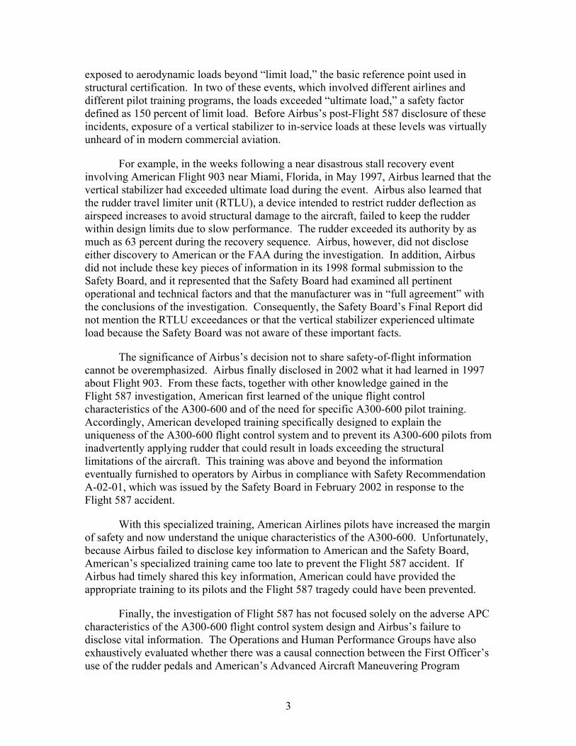
exposed to aerodynamic loads beyond “limit load,” the basic reference point used in structural certification. In two of these events, which involved different airlines and different pilot training programs, the loads exceeded “ultimate load,” a safety factor defined as 150 percent of limit load. Before Airbus’s post-Flight 587 disclosure of these incidents, exposure of a vertical stabilizer to in-service loads at these levels was virtually unheard of in modern commercial aviation.
For example, in the weeks following a near disastrous stall recovery event involving American Flight 903 near Miami, Florida, in May 1997, Airbus learned that the vertical stabilizer had exceeded ultimate load during the event. Airbus also learned that the rudder travel limiter unit (RTLU), a device intended to restrict rudder deflection as airspeed increases to avoid structural damage to the aircraft, failed to keep the rudder within design limits due to slow performance. The rudder exceeded its authority by as much as 63 percent during the recovery sequence. Airbus, however, did not disclose either discovery to American or the FAA during the investigation. In addition, Airbus did not include these key pieces of information in its 1998 formal submission to the Safety Board, and it represented that the Safety Board had examined all pertinent operational and technical factors and that the manufacturer was in “full agreement” with the conclusions of the investigation. Consequently, the Safety Board’s Final Report did not mention the RTLU exceedances or that the vertical stabilizer experienced ultimate load because the Safety Board was not aware of these important facts.
The significance of Airbus’s decision not to share safety-of-flight information cannot be overemphasized. Airbus finally disclosed in 2002 what it had learned in 1997 about Flight 903. From these facts, together with other knowledge gained in the Flight 587 investigation, American first learned of the unique flight control characteristics of the A300-600 and of the need for specific A300-600 pilot training. Accordingly, American developed training specifically designed to explain the uniqueness of the A300-600 flight control system and to prevent its A300-600 pilots from inadvertently applying rudder that could result in loads exceeding the structural limitations of the aircraft. This training was above and beyond the information eventually furnished to operators by Airbus in compliance with Safety Recommendation A-02-01, which was issued by the Safety Board in February 2002 in response to the Flight 587 accident.
With this specialized training, American Airlines pilots have increased the margin of safety and now understand the unique characteristics of the A300-600. Unfortunately, because Airbus failed to disclose key information to American and the Safety Board, American’s specialized training came too late to prevent the Flight 587 accident. If Airbus had timely shared this key information, American could have provided the appropriate training to its pilots and the Flight 587 tragedy could have been prevented.
Finally, the investigation of Flight 587 has not focused solely on the adverse APC characteristics of the A300-600 flight control system design and Airbus’s failure to disclose vital information. The Operations and Human Performance Groups have also exhaustively evaluated whether there was a causal connection between the First Officer’s use of the rudder pedals and American’s Advanced Aircraft Maneuvering Program
3

(AAMP). Despite an intensive effort to determine if AAMP somehow overemphasized the use of rudder, this investigation has not shown that American’s training prompted or promoted the pilot’s cyclic rudder pedal inputs. And the fact that other operators with different training programs also experienced high load A300-600/A310 events further highlights the point that there is no connection between the pilot’s use of rudder and American’s training program.
PROBABLE CAUSE AND CONTRIBUTING FACTORS
The probable cause of this accident was the onset of a design-induced, adverse aircraft pilot coupling (APC) event that led to rapid development of excessively high aerodynamic lateral loads resulting in the catastrophic structural failure of the vertical stabilizer and rudder in only six and one-half seconds.
The event was triggered by an unexpectedly sensitive response of the rudder to an initial, single pedal input by the pilot during a wake vortex encounter. Due to the unique characteristics in the aircraft’s flight control system design, the pilot became caught in an adverse APC/pilot involved oscillation mode as he attempted to counter the effects of that input. Specifically, after making a control wheel input followed by a rudder input intended to achieve a desired aircraft response, the over-sensitivity of the rudder control system induced the pilot to make additional, essentially cyclic, corrective rudder inputs as he attempted to stabilize the aircraft. Unknown to the pilot, because of the sensitivity of the rudder controls and the powerful nature of the hydraulically driven rudder actuators, these corrective inputs rapidly generated rupture loads. The rudder travel limiter unit (RTLU) and yaw damper failed to protect against the build up of these loads due to deficiencies in the flight control architecture design.
Contributing factors to the accident included:
1. The manufacturer’s failure to disclose information learned from prior in-service high-load events demonstrating the adverse APC characteristics of the A300-600 flight control system and the resulting risk of structural overload;
2. Extraordinary rudder sensitivity at increased airspeeds due to a high rudder pedal breakout force relative to the shallow (low) rudder pedal force gradient and a corresponding reduction in rudder pedal travel that makes the A300-600 uniquely susceptible to adverse APC/pilot involved oscillation;
3. The rudder travel limiter unit’s inability to protect the aircraft from excessive lateral loads;
4. The inability of the yaw damper, when the rudder pedal is held at the stop, to damp out motions resulting from the adverse APC/pilot involved oscillation tendencies of the aircraft;
4

5. Industry-wide lack of awareness before the accident of the catastrophic potential of rudder reversals, even at speeds below design maneuvering speed;
6. Industry-common, but incorrect, pilot assumptions about aircraft maneuvering speed based upon prevailing definitions of the term; and
7. The lack of clear regulatory verification requirements to identify and correct adverse characteristics through flight-testing and evaluation of handling qualities of flight control systems during original, as well as subsequent, “derivative” model, aircraft certification.
II. ORGANIZATION OF SUBMISSION
This investigation has raised complex human performance, structures, operations, certification, aerodynamics, materials science, aircraft systems, and system safety issues. To understand the cause of this accident, one must understand (1) the Airbus A300-600 rudder control system design, including its evolution from earlier models; (2) rudder limiting methodologies used by other major manufacturers; (3) flight control system certification philosophy; (4) APC principles; and (5) the perceptions associated with the term maneuvering speed. It is also important to understand the role of the wake vortex in triggering the sequence of events leading to the accident and why American’s upset recovery training was not a factor in the accident. Consequently, American has divided these key topics into the following sections:
A. Flight Control Design and Rudder Limiting Methodology
B. The A300-600/A310 Rudder Control System
C. Aircraft Pilot Coupling (APC) and Pilot Involved Oscillation
D. Airbus A300-600 and A310 High Load Events
E. Certification
F. Pilot Awareness and Perception of Maneuvering Speed and Rudder Limiting Protection
G. American’s Pilot Training Program
H. The Effect of Wake Turbulence
Discussion of these topics is followed by a summary of the analysis, followed by proposed probable cause findings as well as suggestions for recommendations the Safety Board should make as a result of this investigation.
Also accompanying this Submission is an Addendum consisting of all source materials relied upon or referenced by American. Several of the documents in the Addendum are subject to a confidentiality order entered in the United States District Court for the Southern District of New York, where civil litigation arising from this accident is pending. These documents consist of or discuss in substance various internal
5

Airbus memoranda and communications. Airbus produced these memoranda and communications to American during the course of discovery proceedings, but marked the documents “Confidential.” Consequently, the confidentiality order automatically governs dissemination of the documents and neither the documents nor their contents may be disclosed publicly without Airbus’s consent or a court order. In accordance with its obligations under the confidentiality order, American has removed certain materials from the copies of the Addendum being provided to the Investigator-in-Charge for filing in the Safety Board’s Public Docket and to the investigation parties. Complete copies of the Addendum are being provided to the Investigator-in-Charge for distribution to Board Members and NTSB staff. American also is providing the Safety Board and the NTSB staff with CD ROM copies of the Submission containing hyperlinks to the sources referenced in the Addendum. American respectfully requests the Board Members and staff to treat the Addendum as confidential and the Investigator-in-Charge to ensure that the Addendum containing documents marked confidential is not placed in the Public Docket or released to any non-Safety Board personnel without Airbus’s consent or a court order.
III. FACTUAL ANALYSIS
Flight 587 crashed following a sudden, catastrophic failure and separation of the vertical stabilizer and rudder during a clear weather climb out from John F. Kennedy International Airport in New York on November 12, 2001. The vertical stabilizer and rudder on the aircraft (an A300B4-605R, Registration N14053) separated from the airplane due to excessive aerodynamic forces after the First Officer, the pilot who was flying, made flight control inputs in response to a wake vortex produced by a departing Japan Airlines Boeing 747-400. After the vertical stabilizer and rudder separated, the aircraft crashed in a residential area of Belle Harbor, New York, killing all 260 passengers and crew along with five persons on the ground. A detailed summary of the History of the Flight is set forth in the accompanying Addendum at Tab 1.
A. Flight Control Design and Rudder Limiting Methodology
Synopsis: The design of the Airbus A300-600/A310 rudder control system is unique compared to other transport category airplanes, and it lacks protective features found in other designs.
Aircraft equipped with engines mounted off the aircraft centerline can produce a yawing moment with asymmetric thrust. In general, greater engine power, and engines spread farther apart, will produce greater potential yawing moments. To accommodate the potential for asymmetric thrust due to power loss, especially at takeoff, airplanes are equipped with vertical stabilizers and rudders measured to a size sufficient to counteract, with some safety margin, asymmetric thrust at maximum power and under calculated worst-case conditions.
Vertical stabilizers and rudders are subsonic, symmetric airfoils. And their capability to induce yawing moments (or sideslip) increases significantly with velocity.
6
They must be strong enough to withstand the anticipated aerodynamic forces (or loads) the aircraft will encounter in turbulent and/or gust conditions, sideslip angle build-up, or when the rudder is used.
On airplanes without a hydraulically powered rudder, direct aerodynamic force feedback and pilot leg strength limit rudder output in most conditions. As airspeed increases, the counteracting aerodynamic forces move against the direction of the desired rudder deflection. The limits of the pilot’s leg strength can define the maximum rudder deflection possible at any airspeed, and hence define the strength requirements of the vertical stabilizer.
By comparison to manually driven systems, hydraulically powered flight controls installed on modern jet transports such as the Airbus A310 and A300-600 are not regulated or limited by pilot leg strength and, in some installations, are capable of rapidly generating relatively large control surface deflections at any airspeed. These systems substitute artificial feel, typically delivered by springs, for the naturally produced aerodynamic resistance of a non-hydraulically driven rudder control. To reduce the potential for structural problems that could be caused by powerful actuators at high airspeeds, aircraft designers usually include limiting devices as part of the rudder control system to restrict rudder travel as airspeed increases. Manufacturers employ a variety of flight control design concepts and methods to limit the allowable travel of a hydraulically powered rudder at various airspeeds and configurations; however, each generally falls into one of three broad categories: rudder ratio changer systems, hinge moment limiting (or “blowdown”) systems, or mechanical rudder travel limiter systems.
1. Rudder Ratio Changer Systems
A rudder ratio changer system limits rudder deflection proportionately to the increase in airspeed by means of a gearing linkage between the pedals and the rudder. Full range of pedal travel is always the same regardless of airspeed, and changes in airspeed do not affect the artificial feel characteristics of the system. In other words, the feel and response of the rudder pedal remains consistent to the pilot regardless of airspeed. Generally, the ratio changer mechanism is designed to produce a constant aircraft response to a given amount of pedal displacement and force, regardless of airspeed. Typically, traditional yaw dampers in this type of system function by sensing yaw rate, lateral accelerations, and/or computing sideslip angle rate of change over time, and then automatically adding or subtracting rudder as necessary to achieve the desired yaw rate or sideslip. Significantly, yaw damper authority to reduce the rudder from the maximum allowable deflection cannot be unknowingly suppressed by pilot rudder pedal inputs. (Ratio changer systems are found on the original A300B2/B4, as well as the Boeing 747, 757, and 767.)
2. Hinge Moment Limiting (or “Blowdown”) Systems
On an aircraft equipped with a hinge moment limiting (or “blowdown”) system, a device is employed to limit the force capability of the hydraulic actuators, and thereby aerodynamic forces limit the maximum rudder deflection output as
7
airspeed or aircraft configuration changes. Alternative designs in hinge moment limiting systems include using hydraulic pressure reducers, limiting the size of the actuators, and automatically disengaging certain actuators (in systems using multiple actuators). On a hinge moment limiting system, the rudder is described as being “blown down” because, at a given point, the system no longer is able to counteract dynamic air pressure as airspeed increases; this is somewhat similar to systems that are not hydraulically powered. Unlike the ratio changer designs, the pedals in a hinge moment limiting system design are linked to the rudder at a constant ratio. As airspeed increases, the maximum available pedal travel distance from neutral rudder to full deflection (and, consequently, the “artificial feel” force at the pedals) decreases.
The “blowdown” feature also restricts the authority of the yaw damper to act independently in the aerodynamic regime of hinge moment limiting. In areas of the flight envelope that are not at the hinge moment limit of the rudder output, the yaw damper system remains fully active regardless of pilot input. However, when being hinge moment limited, the combined sum of all inputs to the rudder, including pedals, yaw damper, and autopilot, is limited by the available hydraulic actuator power to overcome the resistant aerodynamic forces, which in turn reduces the capability to cause structural damage.
3. Mechanical Rudder Travel Limiter Systems
A mechanical rudder travel limiter system features a device that physically limits the rudder in proportion to changes in airspeed. A300-600/A310 aircraft are equipped with such a device, which is referred to as the rudder travel limiter unit (RTLU). Like the pilot flight control feedback of a hinge moment limiting system, available rudder pedal travel, as well as the artificial feel forces, decreases in a mechanical limiting system as airspeed increases. However, the mechanical limiter differs from hinge moment limiting because the mechanical system (the RTLU on the A300-600/A310) depends upon a moving, mechanical “hard stop” to regulate the maximum amount of available rudder. If not for the hard stop, the hydraulic actuators have the potential to move the rudder farther against aerodynamic forces. The yaw damper will also respond when appropriate to “add” or “subtract” rudder.
Moreover, mechanical limiters vary significantly from one another in the amount by which pedal travel is restricted as airspeed increases. They also differ from one another in (1) how the artificial feel unit is set to generate both a “breakout” force, which is the minimum force required to start the pedal moving, and (2) the added increment of force required to move the rudder pedal following breakout from neutral to full available deflection. Combined, these pedal travel and force characteristics, which define the sensitivity of the rudder control system, commonly are referred to as the “force gradient.”
Although generic, qualitative comparisons between different rudder control systems are difficult to draw, a rudder ratio changer-based system provides more consistent control system feedback (feel) to the pilot throughout the flight envelope than other rudder control system types. With a ratio changer system, airspeed fluctuations
8
have no effect on the rudder pedal travel or the force required to move the pedals; the pilot experiences the same pedal “cues” for a given aircraft response regardless of airspeed. Ideally, all three systems are designed to allow adequate rudder control authority when needed, while simultaneously preventing excessive rudder deployment in airspeed ranges where high aerodynamic forces can cause structural damage. Nevertheless, not all manufacturers’ systems, even within a single type-category such as ratio changers, accomplish these tasks in the same manner or deliver the same handling characteristics.
Control sensitivity, the lack of secondary protective features, and the concept of force gradient are crucial to understand the adverse APC tendencies of the A300-600 and how these characteristics contributed to the Flight 587 accident. As explained in more detail below, the A300-600/A310 series use a combination of flight control system features unlike that of any comparable transport category aircraft.
B. The A300-600/A310 Rudder Control System
Synopsis: The pedal force-feel gradient and the placement of the yaw damper on the A300-600/A310, a design feature unique to these aircraft, allowed excessive movement of the rudder, which led to the development of extreme aerodynamic forces on and structural overload of the vertical stabilizer on Flight 587.
1. The Sensitivity of the A300-600/A310 Rudder Control System
The A300-600 and its shorter fuselage “cousin,” the A310, use a rudder travel limiter unit (RTLU), which controls a single rudder attached to the vertical stabilizer to provide yaw control. Three hydraulic rudder actuators power and move the rudder and are situated in close proximity along the lower third of the trailing edge of the vertical stabilizer. The primary rudder controls are mechanically operated by cables and torque tubes from the pedals, which, along with yaw damper, autopilot, and rudder trim, connect to the rudder actuators through a “summing” mechanism located in the aft fuselage below the vertical stabilizer. The summing mechanism combines the total control inputs from all sources into a single rudder command to the actuators. The rudder actuators are powered by three separate hydraulic systems, each independently operating at a continuous 3,000 pounds per square inch.
The A300-600/A310 rudder control system regulates maximum allowable rudder deflection by means of the RTLU’s moving cam-like feature that physically limits the available range of rudder motion. Another device called the variable stop actuator (VSA), which is an electrical jack-screw controlled by the feel and limitation computers aboard the aircraft, drives the RTLU to allow either more or less rudder deflection, depending on airspeed. According to Section 1.09.14 of the Airbus Flight Crew Operating Manual (Airbus FCOM), May 1, 2002 (Addendum Tab 2), the RTLU begins to reduce rudder authority at 165 knots. At airspeeds above 165 knots, the RTLU starts reducing the allowable rudder deflection from 30 degrees at 165 knots or lower to a maximum of 3.5 degrees at 310 knots or higher. Because the pedals are linked directly to
9
the rudder, the RTLU also reduces the range of available pedal travel or displacement non-linearly from ± 4 inches below 165 knots to ± 0.75 inches at 310 knots.
Most airplanes equipped with mechanical limiters have additional protective features such as blowdown or a split rudder (a rudder using two independent sections, one of which is disabled at higher speeds) to further reduce the possibility of large sideslip angles producing excessive lateral load forces on the vertical stabilizer. The A310 and A300-600, however, have no such supplemental protection. In addition, and unlike the A300-600/A310, some aircraft with mechanical limiters have engines that are pod-mounted on either side of the empennage (providing near centerline thrust as in the MD-80) and thus require a smaller rudder and less rudder authority in a power loss.
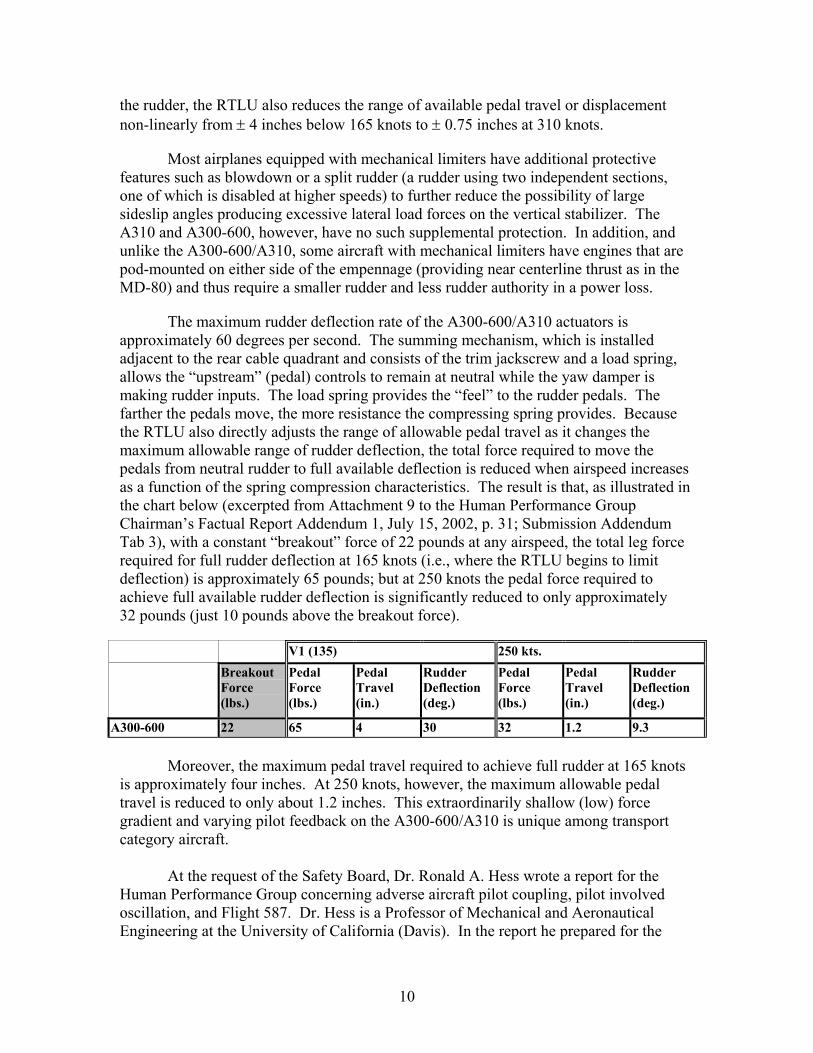
The maximum rudder deflection rate of the A300-600/A310 actuators is approximately 60 degrees per second. The summing mechanism, which is installed adjacent to the rear cable quadrant and consists of the trim jackscrew and a load spring, allows the “upstream” (pedal) controls to remain at neutral while the yaw damper is making rudder inputs. The load spring provides the “feel” to the rudder pedals. The farther the pedals move, the more resistance the compressing spring provides. Because the RTLU also directly adjusts the range of allowable pedal travel as it changes the maximum allowable range of rudder deflection, the total force required to move the pedals from neutral rudder to full available deflection is reduced when airspeed increases as a function of the spring compression characteristics. The result is that, as illustrated in the chart below (excerpted from Attachment 9 to the Human Performance Group Chairman’s Factual Report Addendum 1, July 15, 2002, p. 31; Submission Addendum Tab 3), with a constant “breakout” force of 22 pounds at any airspeed, the total leg force required for full rudder deflection at 165 knots (i.e., where the RTLU begins to limit deflection) is approximately 65 pounds; but at 250 knots the pedal force required to achieve full available rudder deflection is significantly reduced to only approximately 32 pounds (just 10 pounds above the breakout force).
V1 (135) 250 kts. Breakout
Force (lbs.)
Pedal Force (lbs.)
Pedal Travel (in.)
Rudder Deflection (deg.)
Pedal Force (lbs.)
Pedal Travel (in.)
Rudder Deflection (deg.)
A300-600 22 65 4 30 32 1.2 9.3 Moreover, the maximum pedal travel required to achieve full rudder at 165 knots
is approximately four inches. At 250 knots, however, the maximum allowable pedal travel is reduced to only about 1.2 inches. This extraordinarily shallow (low) force gradient and varying pilot feedback on the A300-600/A310 is unique among transport category aircraft.
At the request of the Safety Board, Dr. Ronald A. Hess wrote a report for the
Human Performance Group concerning adverse aircraft pilot coupling, pilot involved oscillation, and Flight 587. Dr. Hess is a Professor of Mechanical and Aeronautical Engineering at the University of California (Davis). In the report he prepared for the
10
Human Performance Group, entitled “An Inquiry into Whether a Pilot-Induced Oscillation was a Factor in the Crash of American Airlines Flight 587” (the “Hess Report”), Dr. Hess concludes at page 11 that “the pedal/rudder sensitivity of the A300-600 at the airspeed at which the AA 587 accident occurred is the highest of all comparative transport aircraft.” Dr. Hess’s report, which is discussed in detail below in Section III C, is Addendum 2, dated December 23, 2003, to the Human Performance Report and is set forth at Submission Addendum Tab 4.
2. The Ability to Modulate A300-600 Rudder Pedal Inputs
as Airspeed Increases
The A300-600 and the A310 evolved from similar, earlier Airbus models designated as the A300B2 and A300B4. A brief summary of the Evolution of the A300 Series of Aircraft is set forth at Addendum Tab 5. Unlike the A300-600 and A310, the B2/B4 used a rudder ratio changer design for rudder control, featuring a device known as the variable lever arm (VLA). The VLA is an electro-hydraulic unit controlled by the feel and limitation computers. On the B2/B4, the VLA adjusts the maximum allowable deflection of the rudder as airspeed changes, but without affecting pedal travel. Airbus made the change for the A310, and subsequently the A300-600, from a ratio changer (VLA) system to an RTLU. The RTLU incorporates a variable stop actuator (VSA), which according to Airbus “is a less complex system. The variable limit[er] is far simpler.” (Transcript of NTSB Public Hearing Day 1, October 29, 2002, p. 89; Addendum Tab 6.) A visual comparison of the VSA and the VLA confirms that the RTLU is less complex, and weighs less. In addition to the change to the RTLU system, the control forces at low speed were reduced by approximately fifty percent. Independently, these changes make the rudder system more sensitive. Combined, they result in an aircraft with undesired handling qualities, which are discussed in detail in Section III C below.
The evolution from the B2/B4 VLA to the A300-600/A310 RTLU resulted in a rudder pedal on the A300-600/A310 that, on the ground and at airspeeds up to 165 knots, has the same pedal travel but half the force of the B2/B4. However, at airspeeds above 165 knots, as the rudder travel is restricted, the RTLU becomes increasingly and uniquely sensitive. At any airspeed below 165 knots, the pedals on the RTLU system uniformly will displace about four inches and require 65 pounds of leg pressure, or 43 pounds above breakout force, to achieve full rudder deflection. Because breakout force remains constant as airspeed increases, while allowable rudder pedal displacement simultaneously is reduced, the force feedback to the pilot between breakout and the displacement required to achieve full rudder deflection diminishes significantly. At 250 knots, it becomes extremely small in comparison to the force feedback of the system at 165 knots. In fact, at 250 knots, 10 pounds of additional leg force over breakout will push the pedals to the mechanical stops using only 1.2 inches of pedal travel.
For any input less than a full rudder command, the force feedback of the RTLU at an airspeed similar to that of American 587 makes it impossible for a pilot to consistently modulate rudder input accurately. The leg muscles (perhaps the least finely calibrated muscles used in controlling the aircraft) that must be used cannot differentiate between
11

very small amounts of pressure in a precise, consistent, or predictable manner. The legs are capable of applying over 400 pounds of force to the rudder pedals. Dr. Hess explains that the “greater muscle size, however, comes at the expense of sensitivity, i.e. the ability of the human to accurately command relatively small forces.” (Hess Report, p. 13.) At airspeeds in the range of 250 knots, where Flight 587 was operating at the time of the accident, it is virtually impossible for a pilot to command anything other than full rudder once he or she applies any rudder pedal force in excess of breakout.
The Human Performance Group ground tests support this conclusion. The Group conducted a variety of instrumented “static airplane” ground tests on an A300-600 in Toulouse, France. These tests used three pilots (a line first officer from the Allied Pilots Association and test pilots from American and Airbus) who were members of the Human Performance Group. All were familiar with the A300-600, and the two test pilots were type rated on the A300-600/A310. (Study Report of Human Performance Ground Test Data, August 19, 2003; Addendum Tab 7.)
Ground Test Report Table 5, shown below and contained at page 10 of the Report of Human Performance Ground Test Data, illustrates the average peak rudder pedal and wheel force in pounds applied by all three pilots when asked to move the pedals full deflection at a simulated airspeed of 240 knots. Since the accident frequency of rudder oscillation was, according to Dr. Hess, approximately 0.5 hertz (a unit of frequency indicating the number of cycles per second), the second line shown on Table 5 is the most relevant simulation. At a frequency of 0.5 hertz and at 240 knots airspeed, all three pilots applied pedal forces (130.2 pounds, 113.7 pounds, and 116.0 pounds) that were three-to-four times the amount required for maximum rudder movement (i.e., only about 32 pounds). The table figures in parentheses show standard deviation.
Ground Test Report Table 5
Ground Test Report Table 6, shown below and also contained at page 10 of the Report of Human Performance Ground Test Data, compares the average peak rudder pedal and wheel force in pounds when the pilots were instructed to apply 50 percent of available rudder (0.6 inches of travel) and wheel at a simulated airspeed of 240 knots. At 0.25 and 1.0 hertz, five out of six attempts exceeded the 32 pounds required for full pedal displacement. The pilots’ inputs were “half the pedal force applied at the 100% condition but the resultant rudder surface motion was still full travel, whereas for the wheel, the reduced force resulted in reduced aileron deflection.” (Report of Human Performance Ground Test Data, p. 16.) Again, the table figures in parentheses show standard deviation.
12

Ground Test Report Table 6
Table 6 is important in understanding Flight 587. Despite the controlled, predictable environment and the lack of external forces acting on the static airplane, none of the pilots in the test was able to input just 50 percent of available rudder when asked to do so. Since the rudder can be moved from neutral to 10 degrees in 0.2 seconds, even a rudder deflection “peak” of 32 pounds of force will result in full rudder. (Hess Report, p. 17.) In other words, the test results indicated that, because of the sensitivity of the A300-600 rudder control system, pilots cannot modulate the rudder between full deflections in conditions similar to those encountered by Flight 587. This phenomenon of full rudder or none is consistent with Dr. Hess’s description of an “on-off” type of movement. (Hess Report, p. 17.)
Despite the A300-600/A310 design, which calls for a decrease in the force required by the pilot to achieve maximum pedal travel as airspeed increases, the test results showed that all three pilots “applied similar or higher pedal force values” as airspeeds increased, and that “the applied pedal forces at airspeeds above 165 knots were greater than required by the system to reach full travel.” In sharp contrast, the applied forces on the control wheel during the tests were consistent with the design of the control wheel system. (Study Report of Human Performance Ground Test Data, p. 16.)
Attachments 9 and 10 to the July 15, 2003 Human Performance Group Chairman’s Factual Report Addendum 1 (shown below and at pp. 31 and 32, respectively, of Submission Addendum Tab 7), depict a comparison of rudder design data among Boeing, former McDonnell Douglas, and Airbus models. (The A320, A330, A340, and B777 are fly-by-wire airplanes and are therefore not comparable to other non fly-by-wire airplanes.)
13

Comparison of the figures for all three manufacturers reveals the following:
• Several aircraft require less than two inches of rudder pedal movement to achieve full allowable rudder at 250 knots. However, the required pedal forces for the A300-600/A310 are significantly lower than other model aircraft.
14

• At 250 knots, the DC-9 and MD-80 have the shortest pedal travel distance for maximum rudder—1.1 inches. However, the pedal force required on these aircraft is 60 pounds with breakout forces of 16 and 15 pounds, respectively. Accordingly, at 250 knots the force above breakout required to achieve maximum rudder is about 45 pounds. On the A300-600/A310, however, the force above breakout required to achieve full rudder is 10 pounds. Also, although not shown on the chart, the DC-9 engines are mounted in the rear along the aircraft centerline, which reduces substantially the rudder authority and size required in the event of a power loss. Additionally, in this part of the flight envelope, MD-80 operations are conducted with the hydraulic pumps in the Low (output) mode. Operation in this condition provides an additional margin of safety by making the rudder control system hinge-moment limited.
• Other than the A300-600/A310, the aircraft showing the smallest difference between breakout force and the force required for full rudder is the B-727, which is 33 pounds. But that is still three times more than the A300-600/A310. Moreover, the B-727 is equipped with a split rudder and blowdown protection, depending on configuration.
• When comparing the differences in force gradient between rudder pedal breakout force and the force required for full deflection at 250 knots, the closest match with the A300-600/A310 (10 pounds) is the B-727 (33 pounds). The aircraft showing the largest differential is the A300B2/B4 (103 pounds).
The data from Attachments 9 and 10 are reflected below in Table 1, entitled “Comparison of Rudder Pedal Responsiveness of Various Transport Aircraft (Airspeed 250 knots),” which appears on page 12 of Dr. Hess’s report. Dr. Hess concludes that “(t)he pedal/rudder sensitivity of the A300-600 at the airspeed at which the AA 587 accident occurred is the highest of all comparative transport aircraft.” (Hess Report, p. 11.)
15

3. Inadvertent Suppression of the Yaw Damper in the A300-600/A310
The lack of blowdown or other protective features on the A300-600/A310 to supplement the protections of the RTLU leaves little margin for error in a system with highly and unusually sensitive rudder pedal controls. The lack of error margin is compounded by the architectural layout which allows the pilot, by design, to unknowingly suppress the yaw damper.
The yaw damper on the A300-600/A310 is designed, like most traditional yaw dampers, to avoid or minimize adverse yawing moments and improve lateral control by automatically commanding rudder outputs in flight as required to maintain stability and improve ride quality. The yaw damper inputs are then “summed” with those from the pedals and are limited, in total, to the maximum rudder deflection allowed by the RTLU for a given airspeed. The yaw damper actuator on the A300-600/A310 has a maximum deflection authority of plus or minus 10 degrees, with a maximum rate of plus or minus 39 degrees per second. And yaw damper outputs are proportionally limited by the RTLU as airspeed increases in much the same manner as rudder pedal inputs are limited.
The Aircraft Performance Group’s analysis shows that the sideslip angle generated and associated lateral G loads sustained by Flight 587 at the point of structural failure and separation of the vertical stabilizer and rudder would have been significantly reduced if Airbus had configured the RTLU differently. And the corresponding bending
16

moment loads would have been well below the previously demonstrated rupture load of the vertical stabilizer.
Figure 1a from the Group Chairman’s Aircraft Performance Study Addendum #1 (October 1, 2003; shown below and at page 16 of Submission Addendum Tab 8), broadly illustrates the placement of the yaw damper within the flight control system architecture. In highly simplified form, the drawing depicts how the RTLU receives pedal and yaw damper inputs from the summing mechanism and translates them to a single rudder actuator command. In typical operation, the yaw damper either adds or subtracts from pedal movements according to the lateral accelerations sensed by the system and its internal logic.
However, because rudder pedal authority is significantly greater than yaw damper authority on the A300-600/A310, a constantly held displacement of the pedal at the pedal travel limit (or stop) set by the RTLU will result in the maximum allowable rudder deflection regardless of yaw damper efforts to reduce the rudder. Essentially, the location of the yaw damper inputs relative to the RTLU allows the pedals to override or suppress the yaw damper.
In short, while yaw dampers are designed to respond when appropriate to “add” or “subtract” rudder, a critical difference between a typical ratio changer and the A300-600/A310’s RTLU is that on the RTLU additional force on the pedals can in certain circumstances suppress the yaw damper and negate its rudder reducing benefit. Consequently, by holding the pedal at the stop, a pilot can unknowingly overpower the yaw damper and negate the yaw damper’s function to reduce or neutralize an excessive rudder deflection command. American is unaware of any engineering justification for Airbus to configure the yaw damper position relative to the RTLU to function in this manner. Airbus’s design choice moreover had profound implications because “suppression of the yaw damper inputs at the rudder limits probably occurred during the accident flight.” (Group Chairman’s Aircraft Performance Study Addendum #1, p. 7.)
The Aircraft Performance Group explored an alternative architectural design layout for the RTLU in which yaw damper commands could not be overridden by pedal
17

inputs. Figure 1b (shown below and at page 16 of the Group Chairman’s Aircraft Performance Study Addendum #1), illustrates the alternative configuration.
By limiting pedal commands separately, and then by again limiting the combination of “net” pedal plus yaw damper inputs, the yaw damper retains its authority to command reduced rudder when needed, irrespective of rudder pedal position or force. Similarly, for a typical ratio changer type system, the pedal stops form the initial “rudder limit,” and the yaw damper can reduce the rudder deflection from that commanded by the pilot. In short, the pilot cannot override the yaw damper with this type of flight control architecture.
The Aircraft Performance Group analyzed the implications of the A300-600 combination of rudder system architecture and lack of hinge moment limiting by creating a mathematical model to evaluate the effect that the alternative configuration, referred to as a “pedal limiter system,” might have had on Flight 587. The Group mathematically modeled Flight 587 without the possibility of suppression of the yaw damper and concluded that “such a system prevents the pilot from overriding yaw damper inputs at the rudder limits, and allows the yaw damper to attenuate (but not prevent) the development of the sideslip angle.” (Group Chairman’s Aircraft Performance Study Addendum #1, p. 14.)
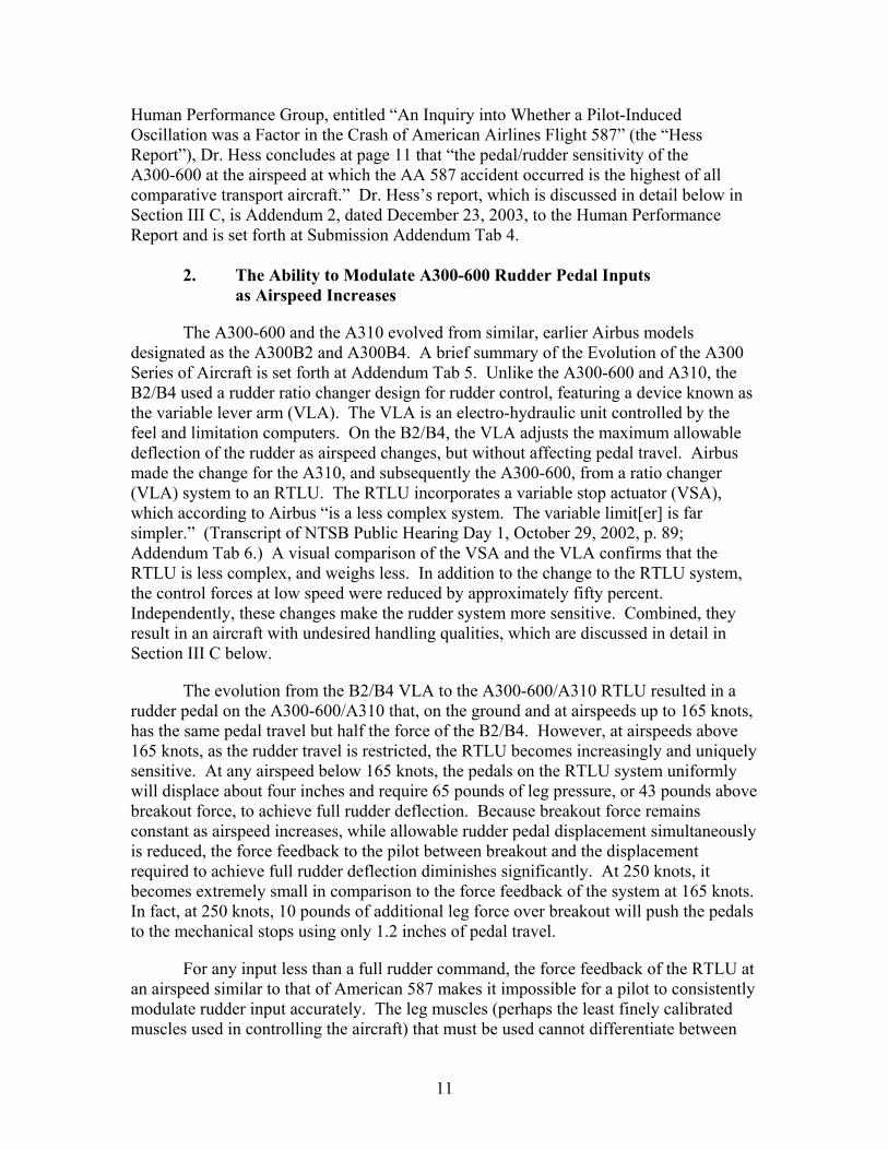
As demonstrated by the chart shown below and at Figure 6g, page 41 of the Group Chairman’s Aircraft Performance Study Addendum #1, the sideslip angle without suppression of the yaw damper is significantly less than when the yaw damper was suppressed when the “loud bang” was recorded on the CVR at time 850.3 seconds, which correlates with 09:15:58.5 EST. (Group Chairman’s Aircraft Performance Study Addendum #1, p. 8.)
18
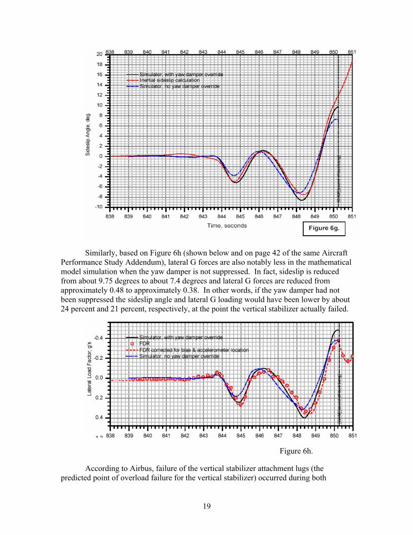
Similarly, based on Figure 6h (shown below and on page 42 of the same Aircraft Performance Study Addendum), lateral G forces are also notably less in the mathematical model simulation when the yaw damper is not suppressed. In fact, sideslip is reduced from about 9.75 degrees to about 7.4 degrees and lateral G forces are reduced from approximately 0.48 to approximately 0.38. In other words, if the yaw damper had not been suppressed the sideslip angle and lateral G loading would have been lower by about 24 percent and 21 percent, respectively, at the point the vertical stabilizer actually failed.
Figure 6h.
According to Airbus, failure of the vertical stabilizer attachment lugs (the predicted point of overload failure for the vertical stabilizer) occurred during both
19

certification and in the accident sequence at a force level corresponding to 1.9 times “limit” load (1.5 times limit load being “ultimate” load for certification purposes). Although the Aircraft Performance Group has not concluded how much this reduction in sideslip would have reduced the stabilizer’s root bending moment, during a July 2002 Airbus presentation in Tulsa, Oklahoma, Airbus stated that sideslip was the most important value in the determination of loads sustained by the vertical stabilizer. Therefore, if the yaw damper would have restricted sideslip to 75 percent of what Flight 587 sustained during the accident, the root bending moment would also have been dramatically less and possibly as low as limit load at the point of failure of the vertical stabilizer.
These findings, however, address only part of the undesirable design characteristics of the aircraft. While different rudder control system architecture almost certainly would have provided the crew more protection and additional time to analyze and possibly solve the problem being caused by the aircraft flight control system before the vertical stabilizer failed, the essential cause of the accident nevertheless is rooted in the adverse APC tendencies of the flight control system.
C. Aircraft Pilot Coupling (APC) and Pilot Involved Oscillation
Synopsis: The A300-600 rudder control system’s conduciveness to severe adverse APC/pilot involved oscillation was the sole reason for the subsequent pedal inputs on Flight 587 after the initial input in response to the second wake turbulence encounter, and was directly responsible for causing structural overload of the vertical stabilizer.
1. The Definition of APC and Pilot Involved Oscillation
Adverse APC events “are inadvertent, unwanted aircraft attitude and flight path motions that originate in anomalous interactions between the aircraft and the pilot.” National Research Council, Aviation Safety and Pilot Control – Understanding and Preventing Unfavorable Pilot-Vehicle Interactions, p. 14 (National Academy Press, 1997) (the “NRC Study”1). Excerpts from the NRC Study are set forth at Addendum Tab 9.
1 This section frequently refers to this influential study, which was authored by the Committee on the Effects of Aircraft-Pilot Coupling on Flight Safety under the auspices of the National Research Council. Members of the Committee were:
Duane T. McRuer (chair), Systems Technology, Inc. Carl S. Droste, Lockheed Martin Tactical Aircraft Systems R. John Hansman, Jr., Massachusetts Institute of Technology Ronald A. Hess, University of California-Davis David P. LeMaster, Wright Laboratory Stuart Matthews, Flight Safety Foundation John D. McDonnell, McDonnell Douglas Aerospace James McWha, Boeing Commercial Airplane Group
20
The aviation community generally is more familiar with the concept of adverse APC as it is known by the term, “pilot induced oscillation” or PIO. However, Dr. Hess, a member of the NRC Committee, and the author of numerous papers on the subject, explained in his report prepared for the Safety Board that “[t]he name pilot-induced oscillation has led to an unfortunate and misleading implication, i.e., that a PIO is the fault of the pilot. Suffice to say, serious PIO events can nearly always be traced to one or more flight control system characteristics that are conducive to PIOs and not to poor piloting skills or aberrant pilot behavior.” (Hess Report, p. 2; emphasis added.)
The term APC encompasses a broad spectrum of unfavorable interactions between the pilot and the aircraft that includes pilot involved oscillation. In part because the acronym PIO is recognizable, the NRC Committee members chose to use it in their paper, but sought to lessen the misunderstanding it causes by changing the words “pilot induced” to “pilot involved” oscillation. The Committee offers the following explanation:
Because the pilot’s actions depend, in part, on the motions of the aircraft in response to pilot commands, the aircraft and pilot dynamics form a closed-loop feedback control system. The pilot is said to be “operating closed-loop” or to be “in the loop.” Adverse APC characteristics can therefore be identified as instabilities in a closed–loop feedback control system. Oscillatory APC events have been the easiest to identify and comprehend and have therefore received the most attention in this study (as they have in the past). These PVS [pilot vehicle system] oscillations will be referred to hereafter as pilot-involved oscillations (PIOs) without thereby ascribing blame. (NRC Study, p. 15; emphasis added.)
Consistent with the NRC Study, the term “pilot involved oscillation” is used in this Submission when referring to the 6.5-second closed-loop sequence of events that led to the structural failure and separation of Flight 587’s vertical stabilizer.
2. Most Severe, Adverse APC Events Are Not Caused by Pilots
While pilot error formerly may have been viewed as the cause of accidents involving adverse APC events, in fact “most severe APC events attributed to pilot error are the result of adverse APC” because it “misleads the pilot into taking actions that contribute to the severity of the event.” (NRC Study, p. 15; Addendum Tab 9.)
The types of pilot control inputs most often associated with APC are described as being “compensatory”; i.e., “the pilot senses a discrepancy between a desired state and an
William W. Melvin, Air Line Pilots Association; Delta Air Lines (retired) Richard W. Pew, BBN Corporation
The Committee was also assisted by “Technical Liaisons” from NASA, FAA, and the US Army and Navy.
21

actual aircraft state (e.g., pitch attitude), and . . . compensates for the errors by providing a corrective input.” (NRC Study, p. 123.) Pilots make compensatory control inputs based on any available sources of information to understand what the airplane is doing. Although cockpit instruments may be included, the most significant sources of pilot feedback, especially if high frequency oscillations are involved, are related to visual, motion, and aural sensations, e.g., accelerations and attitude changes. (NRC Study, pp. 17-18.) Roll rate and pitch rate, both “easily sensed” by the inner ear, were the “primary cues” perceived by the pilots of Flight 587. (Hess Report, p. 14; Addendum Tab 4.) If changing attitude or motion cues prompt a pilot to make a “compensatory” flight control input, which results in an aircraft response inconsistent with what the pilot anticipates or desires, the pilot usually will tend to make another compensatory flight control input. If the reaction/response/reaction cycle continues, the pilot begins to function in what is called a “closed loop”—a term essentially synonymous with adverse APC/pilot involved oscillation.
According to Dr. Hess, “there is general agreement that the contributing factors [to adverse APC] are 1) a demanding flight task, 2) a vehicle with unsatisfactory dynamics, and 3) a triggering event.” Ronald A. Hess, Unified Theory for Aircraft Handling Qualities and Adverse Aircraft-Pilot Coupling, 20 Journal of Guidance, Control, and Dynamics, p. 1141 (1997) (Addendum Tab 10). A triggering event “can cause a pilot to move from non-tracking or low-gain tracking behavior to high-gain tracking behavior. (Hess Report, p. 5.)2 For example, “a sudden and large turbulence encounter can cause a pilot to actively begin high-gain, compensatory attitude tracking when previous to the encounter he/she was only monitoring aircraft trim or making low-gain corrections to vehicle attitude.”
The NRC Committee also noted that “[t]he unexpected and unusual nature of most severe oscillatory APC events implies an unusual precursor or trigger event. The fundamental characteristic of a trigger event is a mismatch between the pilot’s control strategy and the effective aircraft dynamics that are being controlled.” (NRC Study, p. 19; emphasis added.) The Committee divided “trigger” events into three categories: (1) environmental, (2) vehicle (a mismatch between pilot control strategy and aircraft dynamics), and (3) pilot, and concluded that environmental triggers can initiate adverse APC in multiple ways. The most direct way is “an environmental circumstance that requires destabilizing control action.” The Committee also noted that an “example of an environmental trigger is atmospheric turbulence.” (NRC Study, p. 50.)
2 According to Dr. Hess, pilot “gain” is “the sensitivity with which the pilot reacts to a given stimulus. If the situation is deemed urgent, the pilot is likely to react with large corrective inputs even for small stimuli [high gain behavior].” (Hess Report, p. 4.) Conversely, “tracking” is the pilot’s use of “compensatory control behavior in which he/she is attempting to null some perceived system error activity. Here error is not used in the more traditional sense to indicate some type of malfunction, whether human or mechanical, but in a control system sense to indicate that the vehicle response variable of interest is not at some desired or commanded value.”
22
3. The Role of Adverse APC/Pilot Involved Oscillation in Flight 587
Control system design choices leading to severe APC/pilot involved oscillation lie at the heart of the problem with the A300-600/A310 flight control system and were responsible for the cyclic rudder inputs leading to the structural failure and separation of the vertical stabilizer. Coupled with the potentially catastrophic, but previously unknown (to operators) structural consequences of an adverse APC event involving rudder, the susceptibility of the A300/600 and A310 to closed-loop APC/pilot involved oscillation constitutes an undesirable design characteristic in the aircraft flight control system design.
The NRC Committee points out that “severe PIOs are almost always relatively high-frequency oscillations.” (NRC Study, p. 17; Addendum Tab 9.) And according to Dr. Hess’s report, during the accident sequence, flight control inputs were made at the following approximate frequencies: column/0.46 hertz, wheel/0.54 hertz, and pedal/0.5 hertz. (Hess Report, pp. 9, 10; Addendum Tab 4.) During that time, the flight control inputs, though rapid, were generally harmonious: i.e., right wheel/right rudder; left wheel/left rudder, indicating that the pilot was attempting to track in response to a series of constantly changing sensory cues.
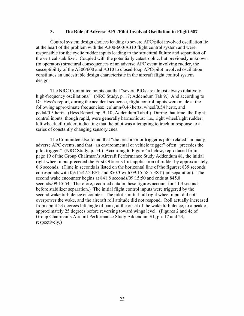
The Committee also found that “the precursor or trigger is pilot related” in many adverse APC events, and that “an environmental or vehicle trigger” often “precedes the pilot trigger.” (NRC Study, p. 54.) According to Figure 4a below, reproduced from page 19 of the Group Chairman’s Aircraft Performance Study Addendum #1, the initial right wheel input preceded the First Officer’s first application of rudder by approximately 0.6 seconds. (Time in seconds is listed on the horizontal line of the figures; 839 seconds corresponds with 09:15:47.2 EST and 850.3 with 09:15:58.5 EST (tail separation). The second wake encounter begins at 841.8 seconds/09:15:50 and ends at 845.8 seconds/09:15:54. Therefore, recorded data in these figures account for 11.3 seconds before stabilizer separation.) The initial flight control inputs were triggered by the second wake turbulence encounter. The pilot’s initial full right wheel input did not overpower the wake, and the aircraft roll attitude did not respond. Roll actually increased from about 23 degrees left angle of bank, at the onset of the wake turbulence, to a peak of approximately 25 degrees before reversing toward wings level. (Figures 2 and 4e of Group Chairman’s Aircraft Performance Study Addendum #1, pp. 17 and 23, respectively.)
23
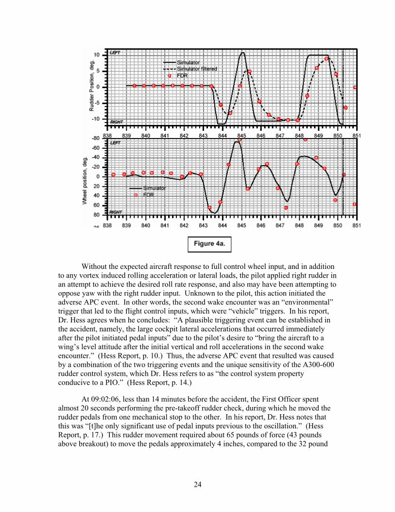
Without the expected aircraft response to full control wheel input, and in addition to any vortex induced rolling acceleration or lateral loads, the pilot applied right rudder in an attempt to achieve the desired roll rate response, and also may have been attempting to oppose yaw with the right rudder input. Unknown to the pilot, this action initiated the adverse APC event. In other words, the second wake encounter was an “environmental” trigger that led to the flight control inputs, which were “vehicle” triggers. In his report, Dr. Hess agrees when he concludes: “A plausible triggering event can be established in the accident, namely, the large cockpit lateral accelerations that occurred immediately after the pilot initiated pedal inputs” due to the pilot’s desire to “bring the aircraft to a wing’s level attitude after the initial vertical and roll accelerations in the second wake encounter.” (Hess Report, p. 10.) Thus, the adverse APC event that resulted was caused by a combination of the two triggering events and the unique sensitivity of the A300-600 rudder control system, which Dr. Hess refers to as “the control system property conducive to a PIO.” (Hess Report, p. 14.)
At 09:02:06, less than 14 minutes before the accident, the First Officer spent almost 20 seconds performing the pre-takeoff rudder check, during which he moved the rudder pedals from one mechanical stop to the other. In his report, Dr. Hess notes that this was “[t]he only significant use of pedal inputs previous to the oscillation.” (Hess Report, p. 17.) This rudder movement required about 65 pounds of force (43 pounds above breakout) to move the pedals approximately 4 inches, compared to the 32 pound
24

force (10 pounds above breakout) to move the pedals 1.2 inches during the period leading to stabilizer separation.
The pilot’s initial rudder pedal displacement was only 1.2 inches in the direction of right rudder. That simple motion started a critical sequence of events ending approximately six and one-half seconds later with the structural failure and separation of the vertical stabilizer. The 1.2 inches of pedal travel translated to a full rudder pedal input requiring only 32 pounds of foot force—an amount 10 pounds greater than the minimum breakout force of 22 pounds. Because the aileron inputs became rate saturated and the approximately one inch “follow on” rudder pedal motions were large in amplitude, rapidly increasing alternating sideslip angles developed, along with associated side load forces in the cockpit and high lateral loads on the vertical stabilizer. By attempting to “track” the aircraft responses in this high-gain, rate-saturated environment, the pilot essentially became “coupled” in an unstable manner to the airplane.
4. Rate Saturation as a Contributing Factor
Rate saturation is a condition in which the flight control actuators are moving at the maximum rate possible; amplitude saturation occurs when a flight control actuator reaches the limit of it travel. Dr. Hess refers to the Human Performance Group’s instrumented ground test wheel and pedal displacement exercises. He sets forth the results for the “full displacement” segment of the exercises in his Report at Figures 8 and 9, respectively. (Hess Report, p. 16; Addendum Tab 4.) According to Dr. Hess, the full pedal displacement experiments are of particular interest “because this motion and frequency closely approximates that of the wheel and pedal of AA 587 in the last seconds of flight.” (Hess Report, p. 15.) Dr. Hess points out that Figure 9 (pedal displacement) shows “the rudder actuator quickly amplitude saturating after brief periods of rate saturation.” (Hess Report, p. 17.) In other words, in the ground test exercises, the rudder actuator quickly reached the limit of its travel after just briefly moving at its maximum possible rate. Dr. Hess further states in his report that “these characteristics could again be attributed to the sensitivity of the pedal/rudder system.” (Hess Report, p. 17.) And he concludes that “activity consistent with a lateral-directional [APC/pilot involved oscillation] was evident in the moments before the crash of AA 587.” These lateral-directional oscillations were, according to Dr. Hess, “likely accompanied by a similar oscillation in the longitudinal axis” of the aircraft, and “there was a high probability of rate saturation of the aileron and rudder actuators during the oscillations.” (Hess Report, p. 18.)
Section 5.3 of the Study Report of Human Performance Ground Test (pp. 12-15; Addendum Tab 7) addresses rate saturation during input of wheel and rudder, which was observed in several of the 0.5 hertz and 1.0 hertz frequency simulations. Dr. Hess notes that the test data from the ground test exercises indicates that the pilot can move the rudder ± 10 degrees (full opposite deflection) in approximately 0.35 to 0.4 seconds at 240 knots, which is the equivalent of neutral to ± 10 degrees in less than 0.2 seconds. Referring to a recognized, published APC study, Dr. Hess points out that in aircraft flight control development, the following designs should be avoided: “[t]hose which permit the pilot to generate large control surface deflections within about one pilot delay period
25

(0.25 seconds, or so)” – because those designs “will promote PIO.” (Hess Report p. 17; emphasis added.)
5. Consideration by Airbus of the Human Factors Impact of the Transition from the A300B2/B4 to the A300-600/A310
According to the NRC Study, “APC susceptibility has been inadvertently introduced into new aircraft with design changes that were not fully assessed for their impact on APC characteristics.” Consequently, the Committee recommends that program managers and flight control system designers “implement a highly structured systems-engineering approach that involves all relevant disciplines in the APC-elimination process from early in the program through entry into service.” (NRC Study, p. 8; Addendum Tab 9.)
When Airbus developed the A310 as an updated, shorter length version of the A300B2/B4, it substituted the RTLU with a variable stop actuator (VSA) for the original ratio changer or variable lever arm (VLA) design for rudder control on the B2/B4. This change resulted in a mechanically limited rudder control system with significantly different flying qualities. Thereafter, when the A300-600 was introduced, Airbus equipped the aircraft with the same mechanical rudder limiter as the A310. (For additional information, refer to Evolution of the A300 Series of Aircraft; Addendum Tab 5.)
The chart below illustrates the sharp differences in pedal force gradients between the rudder control systems of the A300B2/B4 (103 pounds after deducting breakout force) and A300-600/A310 (10 pounds after deducting breakout force):
V1 (135) 250 kts
Breakout Force (lbs.)
Pedal Force (lbs.)
Pedal Travel (in.)
Rudder Deflection (deg)
Pedal Force (lbs.)
Pedal Travel (in.)
Rudder Deflection (deg)
A300B2/B4 22 125 4 30 125 4 9.3
A310 22 65 4 30 32 1.2 9.3
A300-600 22 65 4 30 32 1.2 9.3
Dr. Hess uses these numbers to compare maximum force and breakout force to determine degrees of rudder per pound of force above the breakout force at 250 knots. He concludes that “the A300-600 pedal/rudder sensitivity is over ten-times greater than” the A300B2 and A300B4. (Hess Report, p. 12; Addendum Tab 4.) This conclusion is illustrated in an excerpt from Table 1, shown below, reproduced from page 12 of Dr. Hess’s report.
26

American has seen no evidence that Airbus ever performed flight tests to gauge the impact of these force gradient changes in the flight control system on the pilot from the perspective of human factors and aircraft handling qualities. Nor has there been any evidence provided that Airbus validated that the introduction of the new system did not create any adverse APC characteristics. As shown by Dr. Hess’s report, Airbus’s apparent failure to conduct a structured, qualitative flight test program to evaluate the RTLU/VSA system for undesirable flight characteristics allowed the introduction of adverse APC tendencies into the A300-600/A310 design.
The Human Performance Group Chairman’s Factual Report Addendum 2, dated October 21, 2003 (Submission Addendum Tab 11), defines rudder control sensitivity as “the magnitude of airplane motion in response to a given amount of rudder pedal force above the breakout force.” The Addendum goes on to state that a “simple measure of airplane motion was defined as the lateral acceleration in the cockpit resulting from the yaw moment produced by the rudder, starting from straight and level flight.” (Human Performance Group Chairman’s Factual Report Addendum 2, October 21, 2003, p. 2.) Figure 1, shown below, from page 7 of the Addendum compares rudder sensitivity of the A300B2/B4 and the A300-600. It indicates that the pedal sensitivity at 270 knots measured in lateral G’s per pound of pedal force was approximately 0.002 and 0.016 for the A300B2/B4 and the A300-600, respectively.
27

Comparison of A300-600 and A300-B2B4 pedal sensitivities.
80 100 120 140 160 180 200 220 240 260 280 300 320 340 360 380 400 420
0.000
0.005
0.010
0.015
0.020
0.025
0.030
0.035
0.040
Ped
al S
ensi
tivity
, g's
/ lb
A300-600 A300-B2B4
Sensitivity = yaw-accleleration induced lateral g's in cockpit per pound of pedal force above breakout force
Calibrated airspeed, kts.
Dr. Hess also refers to a study of APC issues completed in 1996 to illustrate the result of increased control sensitivity in an airframe with desirable flying qualities. (Hess Report; pp. 7-9; Addendum Tab 4.) In that study, one series of experiments involved increasing flight control sensitivity and comparing the pilot involved oscillation ratings (PIORs) assigned by evaluation pilots. The rating scale uses values from 1 to 6 (1 indicates “no tendency” while 6 implies “divergent oscillation” requiring the pilot to release or freeze controls to recover) and was the same scale as the Handling Qualities Rating Method contained in FAA Advisory Circular (AC) 25-7A (1998; Addendum Tab 12), discussed later in this Submission. Dr. Hess concludes that the results of this study “show that by increasing the control sensitivity, alone, an aircraft with exceptional handling qualities (Cooper-Harper rating of 2.0 and PIOR of 1) can be made to be very PIO prone (PIOR of 6).” (Hess Report; p. 9.) (A Cooper-Harper handling quality rating of 2.0 is “good” showing “negligible deficiencies.” G. Cooper and R. Harper, “The Use of Pilot Ratings in the Evaluation of Aircraft Handling Qualities,” NASA TN-D-5153 (April 1969); Addendum Tab 13.)
The study variable of increased sensitivity serves essentially as a mirror of what Airbus did when it replaced the A300B2/B4’s VLA with the A300-600/A310’s RTLU. An airplane with very good handling qualities evolved into one with adverse APC characteristics.
Compared with other modern jet transports, the A300-600 and A310 are the only aircraft that do not have one or more of the following features that reduce adverse APC susceptibility: (1) a rudder ratio changer; (2) a significant force gradient between pedal breakout force and maximum deflection; (3) rudder blowdown protection; (4) a split rudder; and/or (5) a yaw damper that cannot be suppressed by pedal input. Lack of
28

information sharing by Airbus led the aviation community and regulators to overlook the need to study whether the collective absence of these protections constituted a safety compromise. The absence of additional protective features, combined with the unique, adverse APC characteristics of the A300-600/A310, also unknown to the aviation community and regulators before Flight 587, was a recipe for disaster.
6. The BEA’s Comments to Dr. Hess’s Report
Dr. Hess’s findings are based upon his extensive expertise and work in this area and his review of the facts and data from the Flight 587 investigation, including various Human Performance Group data and factual reports. In its January 13, 2004 “comments” to his report, the French Bureau d'Enquêtes et d'Analyses (BEA) does not supply any empirical data, such as flight test reports or other engineering analysis, to challenge Dr. Hess’s findings or the Human Performance Group reports upon which he relied. Instead, the BEA simply disagrees with Dr. Hess’s conclusions.
For example, although the BEA questions the concept of rudder sensitivity, the Human Performance Ground Test Data Report illustrates the negative effects of the shallow rudder pedal force gradient and unique rudder sensitivity of the A300-600 at increased airspeeds. During that test, three different pilots (in various task-targeting exercises designed to measure the time history of forces applied to the rudder pedals and control wheel) each applied over three times the necessary pedal control forces to the aircraft at a simulated 240 knots while manipulating the pedals at a rate (0.5 hertz) equivalent to that shown on the Flight 587 digital flight data recorder. (Study Report of Human Performance Ground Test Data; p. 10; Addendum Tab 7.) The three pilots were also unable to command 50 percent rudder deflection. All of these NTSB tests were conducted in a controlled, aircraft static environment. However, the results would undoubtedly be amplified in a dynamic environment, i.e., an aircraft in flight.
In addition, although critical of Dr. Hess’s use of rudder deflection “per pound of pedal force above breakout” as a basis for comparing the A300-600 and other manufacturers’ aircraft, the BEA overlooks the fact that Dr. Hess also provides a one-on-one comparison between the A300-600 and the A300B2/B4. Comparing these two aircraft, which are sized to one another and use the same vertical stabilizer configuration, “the A300-600 pedal/rudder sensitivity is over ten times greater.” (Hess Report, p.12; Addendum Tab 4.)
Instrumented flight tests by trained test pilots are the best way to conclusively evaluate the flying and handling qualities of the A300-600, and the impact of these flight control sensitivities. Indeed, Airbus should have performed these flight tests for original and derivative model certification. But in the two plus years since the Flight 587 accident, Airbus has not provided the Safety Board or the parties with any flight test data that (1) demonstrates how Airbus evaluated the flying and handling qualities of the A300-600, or (2) shows compliance with Part 25 of the Federal Aviation Regulations during the transition to the RTLU system.
29

D. Airbus A300-600 and A310 High Load Events
Synopsis: Before Flight 587, Airbus was aware of a history of unique, rudder-induced high-load events involving A300-600s and A310s. If Airbus had timely disseminated this information, regulatory authorities, as well as operators, would have recognized the undesirable design characteristics in the flight control system and could have taken corrective actions that likely would have prevented the accident.
1. Airbus’s Knowledge of Other A300-600/A310 High Load Events
A prime focus of the public hearing was the history of certain Airbus in-service events resulting in unusually high aerodynamic loads sustained by the vertical stabilizers of A300-600 and A310 series of airplanes.
Public Hearing Exhibit 7Q (Addendum Tab 14) lists a total of 11 Airbus “high load” events dating back to 1989. Seven of these events involved the A300-600 and four involved the A310. Three of the events, including Flight 587, resulted in exceedances of ultimate load (1.5 limit load) on the vertical stabilizer. All three ultimate load exceedances, plus two events in which the vertical stabilizer was exposed to forces which exceeded limit load, involved rudder reversals.
Significantly, all of the high load events reported by Airbus in Exhibit 7Q involve the A300-6003 and A310—both of which, as previously stated, have the same flight control system, which is unlike the B2/B4 or any other Airbus airplane. (Although the A320 series, A330, and A340 have similar appearing rudder systems, they are fly-by-wire aircraft, and the rudder system would only act like the A310/A300-600 if the fly-by-wire system failed). American’s service history and fleet experience is also informative. American operates over 700 airplanes, 35 of which were A300-600s before the loss of Flight 587. The only record of any exceedances of limit load, much less ultimate load, involving vertical stabilizers in the American fleet is found among the A300-600s (American does not operate A310s). Stated another way, in a span of several decades covering millions of flight hours, the only American Airlines pilots known to have experienced limit load or ultimate load exceedances have come from the relatively small A300-600 pilot community, flying five percent of American’s combined fleet. These events occurred despite the fact that all American pilots are trained under the same training program, including AAMP, and most pilots move among fleets several times in their careers.
The reason for this high load event history is clear. The Airbus A300-600/A310 uses a combination of flight control system features unlike that of any other transport category aircraft in commercial aviation.
3 American Airlines operates more A300-600s than any other passenger airline in the world, and it is the only passenger carrier that operates A300-600s in the United States.
30

The Safety Board requested high load event histories from Airbus and Boeing. As reported on page 4 of the Human Performance Group Chairman’s Factual Report Addendum 2, dated October 21, 2003 (Addendum Tab 11), Boeing maintains records of in-service events and has reported that it “is not aware of any events involving vertical tail loads from in-flight maneuver or gust greater than limit load for any of the company products.” Boeing’s review also included the service records of former McDonnell Douglas aircraft. On the other hand, Table 1 on page 5 of the Addendum, reprinted below, summarizes what American characterizes as Airbus’s unique high load event record:
Table 1. Airbus service history of high tail load events (tail load > 1.0LL).
Model number of events number of events Flight hours exceeding limit load involving pilot input of world fleet
A-300-B2-B4 0 0 9,635,000 A310 3 3 9,200,000 A300-600 4 3 6,256,000 A320 0 0 28,164,000 A330 0 0 A340 2 0 8,613,000
________________________________________________________________________
Based on concerns about adequacies in the certification process for commercial aircraft, including aircraft operated under Part 121 of the Federal Aviation Regulations, the FAA commissioned the Commercial Airplane Certification Process Study (CPS) in early 2001. (Addendum Tab 15.) The CPS Team’s 2002 final report states that human performance is a “dominant factor” in aircraft accidents. And human performance requires “attention to all the human interfaces involved in design, operation, and maintenance of an airplane.” The CPS Team points out, however, that there still is no defined system in place to evaluate the human performance element in the operation or maintenance of a specific aircraft “system design.” (CPS Team Report; p. 8.)
One of the conclusions of the CPS was that “many of the accidents reviewed during this study followed one or more previous incidents that were not acted upon because those involved in industry and government were unaware of the significance of what they had observed.” (CPS Team Report; pp. xxi-xxii.) The study warns that “[r]egardless of the reasons, failure to capture adequately the important lessons of the past sets the stage for the repetition of past errors.” (CPS Team Report; p. 50.)
As shown below, there were at least three incidents before Flight 587 involving the A300-600/A310 that Airbus failed to warn operators and pilots about and failed to “act upon” internally.
31

a. Interflug (Event H on Exhibit 7Q)
On December 1, 1991, an Interflug Airlines A310 experienced a series of stalls during a go-around at Moscow. Lateral loads on the vertical stabilizer exceeded ultimate load during the event due to rudder reversals. As pointed out by American in correspondence to the Safety Board, Airbus knew in 1991 that the aircraft underwent severe lateral accelerations resulting from the rudder reversals and either knew or should have known that the vertical stabilizer had been exposed to dangerously high loads, including ultimate load and greater. (American letter dated June 10, 2003, referencing internal Airbus documents about the Interflug event; Addendum Tab 16.) Copies of the Airbus documents with specific references to Airbus’s post-event investigation findings were provided to the Safety Board in a follow-up American letter dated October 13, 2003. (Addendum Tab 13.) (The June 10 and October 13 letters also address another high load event, which is discussed at “c” below.)
b. American Flight 903 (Event B on Exhibit 7Q)
On May 12, 1997, American Airlines Flight 903, an A300-600, inadvertently stalled in a holding pattern near West Palm Beach, Florida. During recovery, the vertical stabilizer sustained loads exceeding ultimate load due to multiple rudder reversals. Internal Airbus documents indicate that it knew in June 1997 that the vertical stabilizer exceeded ultimate load. Airbus documents obtained by American in the course of litigation stemming from the Flight 587 accident were provided to the Safety Board. (American letter dated December 20, 2002, showing “timeline” of key events related to Flight 903; Addendum Tab 18.) Copies of the timeline-related Airbus and American documents referred to in the December 20 letter were provided to the Safety Board in a follow-up American letter dated January 6, 2003. (Addendum Tab 19.) These letters and documents were in response to a December 17, 2002 request to American from the Safety Board. (Addendum Tab 20.)
In addition to the exceedance of ultimate load, the Airbus documents establish that Airbus also knew in June 1997 that the rudder travel limiter did not restrict the rudder to its design limits during the recovery sequence because of the rapid accelerations of the aircraft. According to Airbus calculations at the time, rudder deflections during the event exceeded rudder travel limiter unit (RTLU) limits by as much as 63 percent. (June 16, 1997 timeline entry, American letter of December 20, 2002; Addendum Tab 18.)
An example of Airbus’s understanding of loads sustained by Flight 903 is found in a Public Hearing Exhibit. On June 19, 1997, an Airbus employee indicated in an internal e-mail that digital flight data recorder (DFDR) analysis “confirms high lateral load factors both for longitudinal and lateral aspects.” (Public Hearing Exhibit 7-LL, p.4; Addendum Tab 21.) The e-mail message reports that the loads were lower than “previously announced,” indicating an ongoing analytical effort. The e-mail specifically states that “it appears that for some areas of the airplane limit design loads have been exceeded and for some others such as rear fuselage, fin and empennage the ultimate design loads could have been reached.” (Public Hearing Exhibit 7-LL, p. 4; emphasis
32
added.) Additional information concerning Airbus’s knowledge about Flight 903 is contained in the Flight 903 timeline of American’s letter dated December 20, 2002.
The Flight 903 event was investigated by the Safety Board as an accident due to the nature of the occurrence and because of injuries on board. Airbus actively participated in the official investigation and yet failed to inform the Safety Board or American Airlines (1) that the vertical stabilizer had been exposed to lateral loads exceeding ultimate load due to rudder reversals, or (2) that the RTLU had failed to restrict the rudder. Airbus also failed to disclose these facts in its formal technical submission filed a year later and instead represented to the Safety Board that the investigation was “thorough,” that “all significant operational and technical factors have been examined,” and that “Airbus Industrie is in full agreement” with the Aircraft Performance Group’s summary “of the most significant aspects of the event.” (Airbus Flight 903 Submission of August 12, 1998, p. 1; Addendum Tab 22.) The Safety Board (as well as all operators) had no idea of the facts known only to Airbus, and thus did not address the vertical stabilizer structural issues or their ramifications in either the Performance Group Report or the Final Report.
In a July 2002 meeting in Tulsa, Oklahoma, Airbus finally informed American that the vertical stabilizer from Flight 903 had to be replaced because loads at or near ultimate made it impossible to predict the stabilizer’s ability to withstand future loading. (Airbus “Airworthiness Review of A300-600 MSN 513,” July 9, 2002, at slide 27; Addendum Tab 23.) The fact that Airbus elected not to share these concerns earlier with the NTSB, the French DGAC, the FAA, and other operators, especially American, is disconcerting.
c. Air France Flight 825 (Event J on Exhibit 7Q)
On December 1, 1999, Air France Flight 825 experienced an electrical rudder trim input, triggering two rudder reversals while in cruise flight. Internal Airbus documents provided by American to the Safety Board during the investigation of Flight 587 establish that Airbus performed calculations almost immediately after the Air France event and determined that the reversals caused loading on the vertical stabilizer exceeding limit load and near ultimate load. (American letter dated June 10, 2003; Addendum Tab 16; American letter dated October 13, 2003, with attachments; Addendum Tab 17.)
The French BEA was at least initially involved in the investigation, although there is no indication Airbus shared any of its information with BEA investigators.
To American’s knowledge, before Flight 587 Airbus never informed any investigative, regulatory, or certifying authority, or any 300-600/A310 operator, of the fact that any of its aircraft had experienced vertical stabilizer loads exceeding limit or ultimate load. American also believes that Airbus never informed anyone of the crucial, causal connection between these dangerous load exceedances and rudder reversals occurring at speeds below Va.
33

2. Airbus’s Awareness of the RTLU Design Limitations
American’s post-Flight 587 analyses of DFDR data and internal Airbus documents associated with Airbus’s investigation of the Interflug event and American Flight 903, demonstrated not only the hazard of generating high loads on the A300-600 and A310, but also the inability of the RTLU to correctly limit rudder deflection during acceleration. Airbus had the DFDR data from both prior events immediately after they occurred in 1991 and 1997, respectively. Both events involved aerodynamic stalls resulting in a nose-low acceleration during recovery, and both were officially investigated by government agencies.
The RTLUs on both airplanes were unable to adjust for acceleration during the recovery. For example, during the time that the Interflug A310 sustained 0.686 lateral G’s, the RTLU’s theoretical design limit was 5.63 degrees, with an actual limit of 22.10 degrees—almost four times the design limit. Actual rudder deflection was as high as about 15 degrees, the equivalent of over 2.5 times the RTLU’s theoretical limit.
Internal Airbus documents, dated just one month after the May 1997 American Flight 903 accident, indicate that actual rudder travel on Flight 903 also exceeded the design limit of the RTLU. Out of the nine recorded rudder deflection data points during the event, rudder deflection went beyond the limit six times. In one instance, rudder deflection exceeded the limit by 63 percent. Five years after the accident (during an Airbus presentation in July 2002 in connection with its decision to recommend replacement of the vertical stabilizer), Airbus finally told American for the first time that the rudder on Flight 903 had exceeded the RTLU limits and exceeded ultimate load. (Airbus “Airworthiness Review of A300-600 MSN 513,” July 9, 2002, at slide 15; Addendum Tab 23.) When queried about this, the Airbus presenter confirmed that the RTLU was “slow to respond” to acceleration and that this limitation had been a long-term problem with the RTLU and that Airbus was aware of the matter.
The inability of the RTLU to respond to airspeed changes is a design limitation, but it does not appear to be a factor in the Flight 587 accident. It shows, however, that Airbus did not properly analyze and disclose the design limitations and failure modes of the system. If it had done so, that analysis probably would have evolved into a finding that the A300-600/A310 rudder control system needed additional protective features, or at least a warning to operators, to prevent the rudder from generating excessive side loads. Unfortunately, Airbus’s failure to share what it knew about the limitations of the RTLU with its customers was an omission consistent with the more overt troubling history that Airbus has had in not advising government officials or operators of the A300-600/A310’s critical susceptibility to adverse APC characteristics and vertical stabilizer load exceedances.
3. Lack of Airbus Guidance about the Changes in the Rudder Control System from the A300B2/B4 to the A300-600/A310
Airbus’s failure to provide sufficient information to operators and pilots is well illustrated by comparing Airbus-produced operating manuals of the A300-600/A310 and
34

the A300B2/B4. Airbus’s A300-600 Flight Crew Operating Manual (Airbus FCOM) Section 1.09.14 (Addendum Tab 2) states that the RTL systems “progressively decrease the maximum rudder travel from ± 30 degrees below 165 kt (low speed range) to ± 3.5 degrees above 310 kt (high speed range).” American has researched comparable guidance for the A300B2/B4. An Airbus A300B2/B4 manual states: “The rudder variable lever arm unit reduces the pedal-rudder deflection ratio from ± 30 degrees (at speeds below 165 kias [knots indicated airspeed]) to ± 5 degrees (at high speeds).” (Airbus A300B2/B4 Operating Manual; Addendum Tab 24.)
As shown above, Airbus’s guidance on yaw control to pilots of the two different series of airplanes was virtually identical, even though the airplanes have very different rudder control systems. And the A300-600 FCOM fails to provide any information about the operational differences between the two rudder control systems. Nor has this investigation revealed any Airbus training material that explains these differences. Especially for operators that only flew the A300-600 or A310, Airbus did not make any information available to alert and enable airline training departments or pilots to become aware of the unusual flight control sensitivity built into these derivatives of the A300B2/B4.
4. Airbus’s Internal Decision Making Process
Most of the light shed in this investigation on Airbus’s knowledge of high load events since 1991 has come as the result of private litigation-related document discovery, the results of which American has shared with the Safety Board. While the Flight 587 investigation has benefited from the litigation discovery process, American does not believe this is an acceptable way for the Safety Board to learn about prior safety-related in-service events during a major accident investigation. Most certainly, the withholding of this kind of information by a manufacturer does not comply either with the letter or the spirit of the Airworthiness Bilateral Agreement between France and the United States (Addendum Tab 25), nor does it enable the FAA and the French General Directorate of Civil Aviation (DGAC) to meet their mandates under the Bilateral Agreement for continued airworthiness monitoring. American has raised these concerns with the Safety Board during the course of the Flight 587 investigation. (American letter dated June 26, 2003; Addendum Tab 26.)
Moreover, the information in this case comes too late to influence the investigation of Flight 903 or enable the Safety Board to issue Safety Recommendations like A-02-01 and 02 (February 8, 2002; Addendum Tab 27) and A-03-41 through 44 (September 4, 2003; Addendum Tab 28) that otherwise could have been issued before Flight 587. American similarly has raised these concerns with the Safety Board during this investigation. (American letter dated September 24, 2003; Addendum Tab 29.) The fact that Airbus allowed the vertical stabilizer of a passenger carrying aircraft to remain in service for five years after it had exceeded ultimate load, until this investigation finally forced Airbus to act, constitutes yet another unnecessary, if not inexcusable, consequence of Airbus’s silence.
35

The significance of Airbus’s decision not to share safety-of-flight information simply cannot be overemphasized. Airbus changed its Flight Crew Operating Manual to warn of the dangers of rudder reversals on the A300-600 only after the Safety Board issued its February 2002 Safety Recommendations A-02-01 and 02. (Airbus A300-600/A310 FCOM Bulletin No. 15/1, dated March 2002; Addendum Tab 30.) This Airbus FCOM change could have been issued well before Flight 587 based on Airbus’s internal knowledge of rudder reversal dangers, as well as the trend of high load events in its A300-600/A310 fleet. Similarly, a December 13, 2002 CD ROM-based Airbus presentation, entitled “Rudder and Loads” (Addendum Tab 32), contains clear and descriptive warnings about the unusual sensitivity of the A300-600/A310 rudder that easily could have been furnished to operators before Flight 587 if Airbus had been forthcoming with this critical information. In this presentation, excerpted below, Airbus specifically warns pilots of the potentially adverse results of “incorrect” rudder use and describes a possible cycle of “Pilot surprise -- Opposite abrupt overreaction on pedals -- Cyclic rudder inputs -- Possible loss of control . . . and excessive loads.” (Rudder and Loads, p. 14.)
PPoossssiibbllee lloossss ooff ccoonnttrrooll ((eexxcceepptt oonn FFBBWW AA//CC
wwiitthh aann aaccttiivvee rroollll rraattee ccoonnttrrooll llaaww))
aanndd eexxcceessssiivvee llooaaddss
PPiilloott ssuurrpprriissee
OOppppoossiittee aabbrruuppttoovveerrrreeaaccttiioonn oonn ppeeddaalls
CCyycclliicc rruuddddeerr iinnppuuttss
s
All of these facts were known to Airbus before November 12, 2001. And if Airbus had shared this information earlier, the Flight 587 accident could have been prevented.
American agrees with the statement of the Safety Board’s Director of Aviation Safety that “Flight loads that nearly reach or exceed ultimate represent a significant safety issue.” (December 17, 2002 request to American from the Safety Board; Addendum Tab 20.) American believes that this investigation should fully explore the manufacturer’s internal decision making processes and procedures, which somehow allowed vital safety information to be withheld for years until a catastrophic accident and civil litigation finally uncovered these facts. Only a thorough investigation into how and why the present system of information sharing failed to work will enable the Safety Board to issue appropriate and effective safety recommendations for future changes.
5. The Need for Ground Training for Adverse APC Susceptible Aircraft and Specific Training for A300-600/A310 Pilots
Because of this investigation, American has learned of the unique A300-600 flight control characteristics and the corresponding need for specific A300-600 pilot training. Without specific training, the A300-600 is far more likely than the rest of American’s
36

fleet to experience adverse APC/pilot involved oscillation and preventable rudder reversals. However, despite the February 2002 Safety Recommendations A-02-01 and 02, there is still a lack of understanding among other pilots and operators worldwide of the catastrophic potential of APC and rudder reversals. American believes the Safety Board should recommend that the FAA require ground training for adverse APC susceptible aircraft with information provided by the manufacturers.
Due to the unique pedal/rudder sensitivity and the lack of APC protective features, American also believes that all A310 and A300-600 pilots should receive specific training in order to avoid the APC susceptibility of the flight control design. Training should also cover the RTLU’s limited capability to accommodate acceleration. In late 2002, American developed such training for all its A300-600 pilots, and it is now part of the A300-600 pilot training program. American believes that Airbus should develop similar training for all A300-600/A310 operators. Pilot awareness of adverse APC issues, and the appropriate training to avoid it, almost surely would have prevented the Flight 587 tragedy.
During the October 2002 public hearing, the Acting Chairman, one Board Member, and the Director of the Office of Aviation Safety stated that understanding Airbus’s state of knowledge before Flight 587 should be a primary goal of this investigation. (Transcript of NTSB Public Hearing Day 3, October 31, 2002, pp. 803-05; Addendum Tab 32.) The overwhelming evidence indicates that Airbus analyzed the DFDR data and determined that dangerously high lateral loads had been sustained in at least the three most significant events occurring before Flight 587. Airbus knew more than anyone about the unique, adverse APC susceptibility and RTLU limitations of the A310/A600-300 in the summer of 1997. (American letter dated December 20, 2002; Addendum Tab 18.) Air France Flight 825 in December 1999 represented another warning sign and yet another missed opportunity for Airbus (1) to disclose what it knew, and (2) to initiate the process of fixing the problem. If Airbus had shared this information during the American Flight 903 investigation, if not sooner, the Safety Board could have issued recommendations like those issued after Flight 587.
Regardless of whether Airbus initially was aware, as they should have been, of these undesirable flight characteristics at the time of certification, it was made aware of them, and the catastrophic potential they created, during the course of the service life of the aircraft following certification and well before Flight 587. Airbus’s failure to take heed of these warnings presented by other high lateral load accidents and near-accidents, and its failure to provide appropriate alerts and information to operators are perhaps Airbus’s most glaring oversights.
37

E. Certification
Synopsis: Part 25 of the Federal Aviation Regulations sets forth airworthiness standards for transport category airplanes, including controllability and maneuverability standards. FAA Advisory Circulars in turn set forth acceptable methods of flight test evaluation to demonstrate compliance with these requirements from a human factors perspective. Derivative certification of the A300-600 and A310, however, apparently did not comply with these requirements. Moreover, Airbus’s failure to disclose subsequent in-service history related to these characteristics undermined the mechanisms for continued airworthiness contained in the bilateral agreement between France and the United States.
The problem of determining how and why the A300-600 flight control system was approved for use in passenger service with these adverse APC susceptibilities compels an examination of the certification of the A300-600 design. Since the A300-600 was designed, manufactured, and originally certified in France, bilateral certification issues arise. Bilateral airworthiness agreements allow the FAA to ensure compliance with the airworthiness standards of the United States by relying upon the certification systems of other recognized civil aviation authorities. The United States and France are parties to an Airworthiness Bilateral Agreement, and each country’s respective civil aviation authority (the Directorate General of Civil Aviation (DGAC) and the FAA) are designated as the “executive agents” responsible to implement the Agreement.
The Bilateral Agreement includes a specific set of Implementation Procedures, which provide that the exporting authority is responsible “for resolving in-service safety issues related to design or production.” (Implementation Procedures, ¶ 3.3.0; Addendum Tab 33.) To accomplish this, the exporting authority “shall provide applicable information which it has found to be necessary for mandatory modifications, required limitations and/or inspections to the importing authority to ensure continued operational safety of the product, part, or appliance.”
The FAA and DGAC also agree to investigate and resolve “all suspected unsafe conditions” and to respond to those conditions with “a mandatory continuing airworthiness action (Airworthiness Directive) whenever the authority determines that an unsafe condition exists in a type certificated product or appliance.”
1. A300-600 Compliance with Advisory Circulars 25-7A and 25-7 or their Substantive Equivalents
American is not aware of any documentation furnished by Airbus, the French DGAC, or the FAA to verify Airbus’s compliance with the standards set by FAA Advisory Circular (AC) 25-7 (Addendum Tab 34), issued in 1986 and in effect when the A300-600 and A310 were certified, or its substantive equivalents. Part 25 of the Federal Aviation Regulations sets forth airworthiness standards for transport category airplanes, including controllability and maneuverability standards. Advisory Circular 25-7A (Addendum Tab 12), entitled “Flight Test Guide for Certification of Transport Category
38

Airplanes,” in turn sets forth current acceptable methods of flight test evaluation to demonstrate compliance with these requirements. Although the 1998 AC 25-7A is an amendment to the original 1986 AC 25-7 and was not yet in effect in 1988 when the A300-600 was certified, AC 25-7A is based upon the same regulations that already applied when the A300-600 was certified and provides some of the FAA’s most useful and instructive insights into the Part 25 requirements relating to APC.
Section 3 of AC 25-7A, entitled Controllability and Maneuverability, provides the following guidance about APC:
Sections (a) and (b) [of Section 25.143] require that the airplane be safely controllable and maneuverable without exceptional piloting skill and without danger of exceeding the airplane limiting load factor under any probable operating conditions. Service history events have indicated that modern transport category airplanes can be susceptible to airplane-pilot coupling under certain operating conditions and would not meet the intent of this requirement.
The Flight Test Guide in AC 25-7A describes events involving the “unpredictability of the airplane’s response to the pilot’s control input” as being consistent with “closed-loop (pilot-in-the-loop) characteristics,” which are adverse APC-related phenomena. It also describes aircraft exhibiting these traits as being “unacceptable for operation within the normal, operations, or limit flight envelopes.” Among various factors, AC 25-7A lists “nonlinearities in the control system” as a possible cause of adverse APC, and it states that “artificial trim and feel systems” providing too small of a displacement and too light of a force gradient “may lead to severe over control.”
Advisory Circular 25-7A also provides APC assessment criteria, which are referred to as the Handling Qualities Rating Method (HQRM), and which are virtually identical to the PIO rating referenced by Dr. Hess in his report. (Hess Report, p.8; Addendum Tab 4.) Advisory Circular 25-7A summarizes the HQRM and contains descriptions of the aircraft dynamics potentially associated with specific APC characteristics along with the FAA rating assigned to each characteristic. Ratings are categorized as satisfactory, adequate, controllable, and unsatisfactory/failed. (AC 25-7A, fig. 20-2; Addendum Tab 12.) An APC characteristic meets one of the two definitions for unsatisfactory/failed when “divergent oscillations tend to develop when pilot initiates abrupt maneuvers or attempts tight control. Pilot must open loop by releasing or freezing the controller.” This characteristic results in a rating of 5 in a scale ranging from 1 to 6 of APC susceptibility characteristics, with 6 being the most severe. As AC 25-7A states, “[i]n cruise flight, forces and airplane response should be such that inadvertent control input does not result in exceeding limits or in undesirable maneuvers.”
These APC ratings are particularly remarkable when compared with public hearing testimony from Airbus’s Loads and Dynamics Manager. When asked what effect releasing the rudder pedals would have had on sideslip, he responded: “if the pilot released the pedal to neutral, he will let the aircraft to come back to its zero sideslip
39

condition.” (Transcript of NTSB Public Hearing Day 3, October 31, 2002, p. 799; Addendum Tab 35.) By releasing the pedal to neutral the pilot would have entered an “open loop.” This characteristic, when considered in light of Dr. Hess’s description of the ground test-simulated rudder cycling “in an ‘on-off’ type of movement,” is synonymous with the APC susceptibility rating of “unsatisfactory/failed” referenced above.
While not containing the same specific guidance relating to the evaluation of APC characteristics, the original version of AC 25-7, issued in 1986, two years before the certification of the A300-600, nevertheless provides for flying qualities evaluation and discusses controllability issues at length. One example (at 20. General – §25.143) states as follows:
Control forces should not be so high that the pilot cannot safely maneuver the airplane. Also, the forces should not be so light it would take exceptional skill to maneuver the airplane without overstressing it or losing control. The airplane response to any control input should be predictable to the pilot.
Another example (in the same section) states: “In cruise flight, forces and airplane response should be such that inadvertent control input does not result in exceeding limits or in undesirable maneuvers.”
Advisory Circular 25-7 highlights the fundamental problem with the A300-600 flight control system that this accident investigation has uncovered. American is not aware of any documentation furnished by Airbus, the French DGAC, or the FAA to verify Airbus’s compliance with the standards set forth by this section. It is wholly unknown at this time whether or to what extent Airbus: (1) performed actual flight tests on the A300B2/B4 to explore the possibility of adverse flight control system handling qualities across the envelope; (2) repeated similar flight tests during certification of the A310 and/or the A300-600 after changing the flight control system; or (3) simply relied on the previous (and obviously inapplicable) results of the B2/B4 tests.
As can readily be seen, Dr. Hess’s conclusions in this investigation about the flight control system sensitivity of the A300-600 mesh seamlessly with the cautions of Advisory Circulars 25-7 and 25-7A for adverse APC and pilot involved oscillation.
2. Need for Additional Work to Evaluate APC and Human Factors Considerations
The CPS Team concludes their Commercial Airplane Certification Process Study (Addendum Tab 15) with a number of findings, the following of which are particularly relevant to this investigation:
Finding Number 1:
Human Performance is still the dominant factor in accidents:
40

• The processes used to determine and validate human responses to failure and methods to include human responses in safety assessments need to be improved.
• Design techniques, safety assessments, and regulations do not adequately address the subject of human error in design or in operations and maintenance.
Finding Number 8:
Adequate processes do not exist within the FAA or in most segments of the commercial aviation industry to ensure that the lessons learned from specific experience in airplane design, manufacturing, maintenance, and flight operations are captured permanently and made readily available to the aviation industry. The failure to capture and disseminate lessons learned has allowed airplane accidents to occur for causes similar to those of past accidents.
Finding Number 15:
Processes to detect and correct errors made by individuals in the design, certification, installation, repair, alteration, and operation of transport airplanes are inconsistent allowing unacceptable errors in critical airworthiness areas.
Notably consistent with Finding Numbers 1 and 8 is the Safety Board’s September 4, 2003 Safety Recommendations A-03-41 through A-03-44 (Addendum Tab 28), which address the response of operators and manufacturers to in-flight events resulting in high vertical or lateral loading. These Recommendations call for manufacturers to immediately notify the FAA and the certifying authority of such events. American supports these recommendations and believes they are consistent with, and essential to the operation of, the provisions of France - United States Bilateral Agreement Implementation Procedures (Addendum Tab 33), which requires continuous monitoring of in-service events to ensure ongoing safety after initial certification.
The CPS explains that “[t]he sharing of information between manufacturers, airlines and regulatory agencies is an essential element in the certification process and in maintaining the airworthiness of in-service airplanes.” (Commercial Airplane Certification Process Study, p. 49; Addendum Tab 15.) American believes this point is self-evident and finds it remarkable, notwithstanding the fact that the Safety Board’s Recommendations are new, that Airbus did not act on its own to report the trend of high load events that they had been documenting since 1991.
As previously discussed, Airbus stated that it switched to mechanical rudder limiter control system for the A300-600/A310 because it was less complex. But it is not clear what, if anything, Airbus did to evaluate the human factors implications of this change, either in the design and certification stage or when in-service experience became available, to detect possible errors of the kind the CPS Team is concerned with in Finding
41

Number 15 above. If Airbus had properly performed flight tests and evaluations on the mechanical limiter rudder control system, the results, as confirmed by Dr. Hess’s report, would have shown a similarity to the descriptions of undesirable APC characteristics found in AC 25-7 and AC 25-7A. Airbus’s failure to properly perform flight tests and evaluations effectively rendered the DGAC and the FAA unable to perform their respective functions under the Bilateral Agreement.
Adverse APC presents a two-part challenge. First is the “testing, certification, and monitoring” part. Safety Recommendations A-03-41 through A-03-44 filled an immediate gap by reminding the industry of the importance of sharing information. However, the CPS supports a more global safety recommendation to address the critical need for a well-defined, seamless, and continuous process of APC and human factors evaluation across the industry. The process should start with design, testing, and original certification of an aircraft model and then retain the same emphasis and priority throughout the life of the series, including the development of “derivative” models and as field and in-service data becomes available for collection, review, and analysis by the manufacturer.
As explained below, the second part of the adverse APC challenge is “pilot awareness.”
F. Pilot Awareness and Perception of Maneuvering Speed and Rudder Limiting Protection
Synopsis: Before Flight 587, pilots worldwide had a misperception of the term “maneuvering speed,” which led to the erroneous belief that rudder movements at any airspeed below the design maneuvering speed could not cause structural failure.
1. Content of Airbus Manuals before Flight 587 about Rudder Reversals
The Safety Board reached the following conclusion in its February 2002 Safety Recommendations:
[T]he Safety Board has learned that sequential full opposite rudder inputs (sometimes colloquially referred to as “rudder reversals”) – even at speeds below the design maneuvering speed – may result in structural loads that exceed those addressed by the requirements. In fact, pilots may have the impression that the rudder limiter systems installed on most transport-category airplanes, which limit rudder travel as airspeed increases to prevent a single full rudder input from overloading the structure, also prevent sequential full opposite rudder deflections from damaging the structure. (Safety Recommendation A-02-01 and -02, p. 1.)
Before Flight 587, however, Airbus manuals said nothing to dispel these misperceptions. In fact, nothing in the Airbus Flight Crew Operating Manual (FCOM) or Flight Manual, or in any other Airbus publication, told pilots or operators of A300-600
42

and A310 aircraft that the rudder limiter would not protect the aircraft from structural failure caused by rudder reversals.
For example, the Airbus A300-600 Flight Manual addresses maneuvering speed in a section entitled, “Limitations – Airspeeds and Operational Parameters.” (Airbus A300-600 Flight Manual, Section 2.03.01; Addendum Tab 36.) Under the heading “MAXIMUM DESIGN MANEUVERING SPEED Va,” the Flight Manual explains:
Full application of rudder and aileron controls, as well as maneuvers that involve angle of attack near the stall, should be confined to speeds below Va.
On the same page is a chart that defines maximum design maneuvering speed. At 2,500 feet, Va is 273 knots, which is well above the airspeed of Flight 587 during the accident. In other words, Airbus led pilots to believe that they could use full application of the flight controls at speeds below maximum design maneuvering speed without risk of damaging the aircraft.
In fact, before the accident, the Airbus FCOM Abnormal Procedure for an unsafe landing gear (Addendum Tab 37) actually encouraged the use of rudder reversals. According to the then applicable Airbus A300-600 FCOM, Section 2.05.32, the procedure to use in the event of “L/G UNSAFE INDICATION” was:
If one gear remains unlocked, accelerate to Vmax, perform turns to increase the load factor and perform alternating side slips in an attempt to lock the gear.
And, of course, the only way to perform alternating sideslips is to perform rudder reversals.4
In other words, the Airbus-approved procedure at the time of the accident for an unsafe landing gear dictated virtually the same maneuver that is cautioned against in the Safety Board’s February 2002 Safety Recommendation (Addendum Tab 27) and by manufacturers in response to the Recommendation. If followed, the Airbus procedure
4 American was not aware of the aeronautical term “Vmax.” Therefore, American published the procedure’s maximum speed to be 270 knots, which is VLO (maximum velocity for landing gear operation). At 270 knots the RTLU design limit is approximately 7 degrees of rudder deflection. This would require less movement of the rudder pedal and less pedal force than the pilots of Flight 587 experienced at 250 knots. Comparisons previously discussed in this Submission show that rudder sensitivity would be exacerbated at the higher airspeed, and that more rapid movement of the rudder from full displacement (±7 degrees) in one direction to full displacement in the opposite direction would be possible at 270 knots than the accident airplane was capable of commanding (at ± 9.3 degrees full displacement) at 250 knots. Maximum speed for this abnormal procedure would decrease depending on wing flap/slat position.
43

very easily could have initiated an adverse APC event with rudder reversals, and potentially severe structural damage to the aircraft or catastrophic consequences. Nothing in the Airbus procedure cautioned crews about the dangers associated with rudder reversals.
2. Content of Airbus Manuals before Flight 587 about Rudder Pedal Force Feel Gradient
At the time of the accident, the Airbus FCOM informed pilots that the rudder travel limiting unit “progressively decrease[s] the maximum rudder travel from ±30° below 165 kt (low speed range) to ± 3.5° above 310 kt (high speed range).” (Airbus Flight Crew Operating Manual (FCOM) Section 1.09.14; Addendum Tab 2.) That was the full extent of the guidance and system explanation provided to pilots by Airbus about the rudder limiting system function. But as demonstrated earlier in the Submission, Airbus knew before Flight 587 that “rudder reversals” could generate dangerous loads on the vertical stabilizer of A300-600/A310 aircraft. However, nothing in the Airbus FCOM or Flight Manual before Flight 587 explained any details about how the rudder limiter worked in terms of pedal displacement, pedal force, or changes in force gradient as airspeed increased or decreased.
In the February 2002 Safety Recommendations, the Safety Board pinpointed the substance of the issue for the A300-600:
[O]n some airplane types, full available rudder deflections can be achieved with small pedal movements and comparatively light pedal forces. In these airplanes, at low speeds (for example, on the runway during the early takeoff run or during flight control checks on the ground or simulator training) the rudder pedal forces required to obtain full available rudder may be two times greater and the rudder pedal movements required may be three times greater than those required to obtain full available rudder at higher airspeeds. (Safety Recommendations A-02-01 and 02; Addendum Tab 27.)
The Safety Board went on to describe in the same Recommendations how different the force gradient characteristics of some aircraft rudder control systems are (without specifically naming the A300-600) from those of several other types of rudder limiter systems, concluding that some pilots, “[l]acking an awareness of these differences in necessary pedal force and movement[,] . . . [and] sensing the need for a rudder input at high speeds, may use rudder pedal force movements and pressures similar to those used during operations at lower airspeeds, potentially resulting in full available rudder deflection.”
Unfortunately, nothing in the Airbus manuals before Flight 587 described the behavior of the A300-600 rudder control system. Accordingly, pilots were unaware of the propensity of the system to induce excessive rudder deflection at higher speeds, and they had an inadequate understanding of the potential structural consequences of certain rudder movements. In fact, the Safety Board pointed out in Safety Recommendations
44

A-02-01 and 02 that there was a potential for pilots to make “large and/or sequential rudder inputs in response to unusual or emergency situations, such as unusual attitude or upset, turbulence, or a hijacking or terrorist situation.” The Safety Board moreover noted that pilot training programs such as the Upset Recovery Training Aid, created by Airbus and other industry collaborators, actually encouraged pilots to use “full flight control authority (including rudder), if necessary, in response to an airplane upset.”
In short, uncertainty or misunderstanding about the meaning and effect of the term “maneuvering speed,” along with the previously little known vulnerability of the vertical stabilizer, highlight the reason why the piloting community was so surprised by the Flight 587 accident. To pilots, the term Va traditionally meant the airspeed at or below which the pilot can exercise full flight control authority without risk of structural damage. That interpretation basically grew from an understanding that the “structural design limit load” of an aircraft is determined by reference to the forces produced by any foreseeable use of the flight control—hence the terms “structural design limit load” and “full flight control authority” were synonymously linked.
Manufacturers such as Airbus, however, are in the best position to know of discrepancies, if any, between pilots’ and operators’ understandings of the certified safe operating limitations of a particular aircraft and the actual limitations of that aircraft as tested by the manufacturer. Where special, unusual, or not readily apparent flying qualities or handling characteristics of the aircraft potentially may induce a pilot to exercise control inputs exceeding the aircraft’s limitations, the manufacturer must, at a bare minimum, adequately alert pilots and operators. A powerful rudder control system, which becomes increasingly and highly sensitive and difficult, if not nearly impossible, to modulate as airspeed rises, and which is capable of delivering large, rapid yawing moments and loads in excess of what the vertical stabilizer can sustain, is a classic example of an unusual and not readily apparent handling quality that Airbus knew and should have warned operators and pilots about.
G. American’s Pilot Training Program
Synopsis: American Airlines developed its Advanced Aircraft Maneuvering Program (AAMP) in response to an FAA recommendation that airlines should integrate advanced maneuvers training into their pilot training programs. Neither the Operations Group nor the Human Performance Group has found any evidence to link AAMP to the Flight 587 accident. Moreover, AAMP is remarkably similar to the industry-endorsed Upset Recovery Training Aid developed by airlines, labor groups, and manufacturers, including Airbus. Instead, this investigation has established that rudder movements during Flight 587 were classic symptoms of adverse aircraft pilot coupling (APC).
The NTSB has exhaustively evaluated whether there was a causal connection between the First Officer’s use of the rudder and American’s Advanced Aircraft Maneuvering Program (AAMP). Neither the Operations Group nor the Human Performance Group has found any evidence to link AAMP to the accident.
45

Although Airbus has sharply criticized AAMP’s teaching of rudder use, this investigation has not shown that the Captain’s or the First Officer’s 1997 AAMP training prompted either of them to make cyclic rudder pedal inputs. AAMP never taught cyclic use of the rudder. (Although before Flight 587, line pilots did not think that rudder movement below maneuvering speed could generate side loads sufficient to induce structural failure of the vertical stabilizer.) This investigation has established that rudder movements during Flight 587 were classic symptoms of adverse APC. This unstable coupling between the aircraft and the pilot resulted from specific, identifiable, and avoidable characteristics in the A300-600 flight control system design and not from “training.”
1. The Background of American’s Advanced Aircraft Maneuvering Program (AAMP)
American Airlines’ training, including AAMP, is approved and continuously monitored by the FAA. AAMP is an advanced training program for experienced pilots involving airplane upsets: It was not developed for “turbulence” or wake vortex training absent an upset. AAMP was designed to address excessively high pitch attitudes and bank angles as recommended by the FAA. Thus, by definition, Flight 587 was not an “AAMP event.”
Airlines in the United States train pilots primarily based on the information provided by airplane manufacturers, as well as the requirements and guidelines set by the FAA. In response to several safety recommendations issued in the aftermath of a series of loss of control accidents occurring from the late 1980s through the mid-1990s, the FAA concluded that airlines should integrate advanced maneuvers training into their pilot training programs. The FAA, however, did not prescribe exact training requirements, nor did manufacturers provide any procedural guidance for the operators of the airplanes they produced. Accordingly, airlines like American, United Airlines, and Delta Air Lines proactively developed their own in-house training and solicited input from the regulatory agencies, as well as aircraft manufacturers.
At American, these efforts to meet the FAA’s recommendation began in early 1995 and evolved over two years into AAMP. While AAMP was being created and refined, American sought and obtained feedback from the FAA, the NTSB, the United States Military, major manufacturers (Airbus, Boeing, and McDonnell Douglas), NASA, numerous other commercial airlines, pilots organizations (the Allied Pilots Association and the Air Line Pilots Association), and instructors and check airmen from American. American invested two years in developing, refining, and presenting AAMP, not only to its own pilots, but also to instructors, check airmen, and pilots for other airlines worldwide. AAMP’s evolution was methodical and thorough, and the program that developed as a result was, at least in part, the product of input from many experts outside of American Airlines.
In July-August 1995, while AAMP was still in its early developmental stage, American obtained permission from the FAA’s Principal Operations Inspector responsible for oversight of American to include unusual attitude and recovery training as
46
part of its approved program for Selected Events Training in the simulator. At the same time, the FAA provided specific guidance for operators seeking to include “Selected Event Training” (defined as training in recovery from unusual attitudes plus recognition and containment of situations that might lead to unusual attitudes) in their simulator training curricula. (Flight Standards Handbook Bulletin for Air Transportation (HBAT) 95-10 (August 16, 1995); Addendum Tab 38.)
Among the examples of Selected Event Training given by the FAA in HBAT 95-10, were “excessive roll attitudes” in excess of 90 degrees and “high pitch attitudes” in excess of 35 degrees. As part of their Selected Event Training during initial hire and transition training, American’s pilots receive nose high, nose low, and rolling upset maneuver recovery training. AAMP grew out of this early FAA-approved Selected Event Training. And AAMP meets the training goals established by the FAA’s HBAT and the Human Factors Team.
In May 1997, American held a two-day AAMP Industry Conference, which was attended by over 200 leaders from the aircraft industry, including Airbus. AAMP received an overwhelmingly positive response from the conference attendees; virtually all felt the program was a needed, groundbreaking development in pilot training. Three months later, on August 1, 1997, the FAA issued final approval of AAMP. AAMP continued to mature as American responded to industry comments and suggestions for how to improve the program. And AAMP today continues to improve based upon new information and suggestions. Indicative of AAMP’s success is the fact, as pointed out in the Operations Group Chairman’s Factual Report, that since AAMP’s initial rollout, several airlines developed their own unusual attitude training programs modeled after AAMP. (Operations Group Chairman’s Factual Report, September 5, 2002, pp. 17, 18; Addendum Tab 39.)
2. The August 1997 AAMP Letter and American’s Response
Following the May 1997 AAMP conference, representatives of Boeing, McDonnell Douglas, Airbus, and the FAA prepared a letter to American, jointly setting forth comments and suggestions concerning the program they had seen at the conference. The joint letter dated August 6, 1997 (Addendum Tab 40), which was solicited beforehand by American’s Vice President of Flight, was largely complimentary of American and of the training program, with the exception of the fact that it expressed reservation about a perceived emphasis in the lecture materials on use of rudder and raised some questions about the use of simulator training for upset recovery.
Rudder use training. The joint letter was largely a philosophical discussion about alternative training techniques for upset recovery. The writers’ comments, which were not specific to any particular model of airplane or flight control system design, reflected general concern about introducing large sideslip angles if the rudder is used at high angle of attack to help induce roll, potentially resulting in loss of control. The joint letter explained, however, that “a simple rule about rudder usage cannot be stated.” That is because of, among other things, the obvious differences in the flight control systems of various aircraft. The joint letter then stated that “a more appropriate standard is to first
47

use full aileron control, if the airplane is not responding, use rudder as necessary to obtain the desired airplane response
American carefully considered the comments and suggestions in the joint letter and replied on October 6, 1997. (American reply letter dated October 6, 1997; Addendum Tab 41). American’s letter was emphatic in rejecting the notion that AAMP overemphasized the use of rudder and stated that American did not “advocate the introduction of large sideslip angles when flying at high angle of attack.” Instead, “[i]n four different sections of the AAMP, emphasis is focused on the fact that when the airplane is not responding to aileron and spoiler control, you should use smooth application of coordinated rudder to obtain the desired roll response.”
American did not receive a reply to its October 6, 1997 letter, and the writers of the August 1997 joint letter initiated no further contact with American about AAMP. American, moreover, was not advised by its FAA Certificate Management Office of any reported concern over AAMP classroom or simulator training. American is also not aware of any related correspondence between any of the co-signers of the joint letter to other airlines developing programs that were modeled after AAMP or that taught the same key principles and/or procedures. In fact, one of the signatories of the joint letter advised another airline after the letter was written, to get American’s AAMP program when they were developing their own upset training program.
Use of Simulator for upset training. The August 1997 joint letter also raised a question about the potential for simulators used in upset recovery training to create “negative learning” if the simulator programming is manipulated beyond “valid engineering data.” The joint letter, however, did not specifically criticize American’s use of the simulator. In its reply letter, American clarified any underlying misconception that might have prompted concerns by explaining that AAMP simulator training is, in fact, based on programming that maintains the aircraft “well inside its flight envelope.” American added its belief, apparently shared by the authors of the August 1997 joint letter, that simulator fidelity was “reasonably good as long as we remain inside the envelope.” And American went to great effort to make sure that the maneuvers remained inside the manufacturer’s flight envelope during the procedural exercises.
Maneuvers for upset recovery are not contained in any FAA Advisory Circulars for simulator qualification. Similarly, manufacturers do not provide flight test data for such maneuvers as part of their simulator software packages. However, the FAA nevertheless has stated that the emphasis in unusual attitude training is on “recognition and procedures,” with the objective being early recognition by the pilot, followed by proper control inputs. (Operations Group Chairman’s Factual Report, p. 27; Addendum Tab 39.) As is well known among training experts, some of these inputs can be highly counter-intuitive. For example, an instinctive reaction of a pilot faced with an unexpected upset is to pull back on the yoke. However, if an aircraft is already past 90 degrees of bank in an upset, pulling back could lead to a complete loss of control and decreased time for recovery. Thus, American’s focus from the beginning in the AAMP program was “on recognition and basic recovery maneuvers.” Consequently, precise simulator fidelity was not essential to quality upset training. As the FAA has explained,
48
“the use of any training device for procedural instruction is of significant value in preparing flightcrews for events they can never train for in actual aircraft.”5 (Operations Group Chairman’s Factual Report, p. 28.)
Airbus’s criticism of AAMP simulator programming involves the AAMP re-creation of either a “rolling” or “pitching” event by introducing a moment or force and then blanking control effectiveness momentarily so as to allow the unusual attitude to develop. Because the objective of the simulator exercise is to model a random event that overpowers flight control authority long enough to generate an unusual attitude, momentary control blanking offers a more spontaneous and realistic alternative than having the pilots remove their hands from the controls and look away (or close their eyes) while the instructor places the simulator into an unusual attitude. In the AAMP- programmed simulator, once a target attitude is achieved all controls are restored simultaneously, giving the pilot under instruction an opportunity to recover the aircraft with the full authority of all controls. The control blanking and restoring features of the AAMP simulator exercises do not require pilots to use rudder to recover and do not “favor” rudder over ailerons. As pointed out at the public hearing, Airbus’s criticism that the simulator induces “negative learning” is based upon a false premise.
A misunderstanding about AAMP that surfaced early in this investigation, but that was essentially laid to rest at the public hearing, is that the program “encourages” use of rudder for roll control at high angles of attack. As the testimony at the hearing established, AAMP teaches careful use of rudder in “smooth small applications,” and “just the amount of rudder that is needed” to get the desired roll response in circumstances where aileron and spoiler control is either ineffective or exhausted. (Transcript of NTSB Public Hearing Day 2, October 30, 2002, pp. 354-56; Addendum Tab 42.) Significantly, AAMP rudder training is entirely consistent with the Industry Upset Recovery Training Aid (URTA, discussed below), of which Airbus was a major contributor. In fact, AAMP simulator training is less aggressive than the URTA exercises.
5 In its June 18, 1996 report on a study entitled, “The Interface Between Flight Crews and Modern Flight Deck Systems” (Addendum Tab 43), the FAA Human Factors Team recommended: “The FAA should strongly encourage or provide incentives to make advanced maneuvers training an integral part of the training curriculum, especially in recurrent training.” In support of such training, the team acknowledged that simulator fidelity might be a concern. But, it nevertheless concluded that “it is desirable for line flight crews to be exposed to as much of the flight envelope as possible so that in unusual circumstances, it is probable that at least one flight crew member has relevant background or training and can make constructive contributions to detecting and resolving the unusual situation.”
49

3. The Industry Airplane Upset Recovery Training Aid
AAMP and its counterpart training programs at Delta and United were already in the advanced stages of development when a cross-section of aircraft manufacturing and airline representatives under the auspices of the Air Transport Association (ATA) first met and began work in June 1996 to study additional initiatives in response to the Safety Board’s Safety Recommendations. These representatives formed a joint industry working group made up of manufacturers (including Airbus and Boeing), airlines (including American, Delta, and United), and others. The eventual product of this industry group, the Upset Recovery Training Aid (URTA; Addendum Tab 44), or Industry Training Aid as it is sometimes also called, was introduced in October 1998, three years after the FAA HBAT called for upset training.
The URTA represented essentially the first effort to address unusual attitude training in which manufacturers, such as Airbus, became directly involved and supported. Significantly, the URTA is in many ways strikingly similar to the AAMP program that American introduced more than two years before the URTA’s release. Nevertheless, the URTA appears to form the basis upon which Airbus has leveled certain criticisms in this investigation against AAMP. As demonstrated above, those criticisms are unfounded.
4. One Captain’s Observation of Flight 587’s First Officer
During this investigation, an American Captain informed American that he recalled having observed the First Officer of Flight 587 during a flight in 1997. While still a junior Captain on the B727, the pilot stated that on a flight with the First Officer he observed the First Officer use rudder in what he considered to be an “aggressive” manner in response to wake turbulence during climb after takeoff with flaps at 5 degrees. (Operations Group Chairman’s Factual Report, Attachment A, Interview Summaries, pp. 37-40; Addendum Tab 45.) The Captain stated that he criticized the First Officer for his control input. He stated that after leveling off, he and the First Officer discussed AAMP and its instruction about rudder use. The Captain also stated that AAMP did not teach rudder use during wake encounters.
The Operations Group also interviewed the flight engineer who was on duty during that flight. According to the Safety Board’s interview summary, the flight engineer stated he did not recall the First Officer’s rudder use on that flight. (Operations Group Chairman’s Factual Report, Attachment A, Interview Summaries, pp. 41-44; Addendum Tab 46.) He added, however, that if something had yawed the airplane, he would have remembered it. But he did recall a yawing motion. He added that he did recall a “talk” between the pilots on piloting issues, but was not aware of the subject of the discussion or what motivated it.
The Safety Board also interviewed two other Captains who had flown approximately 175 times with the First Officer, predominantly on the A300-600. Neither of these Captains could recall any inappropriate use of flight controls. American also offered a number of other Captains for interviews, which the Operations Group Chairman did not consider to be necessary.
50

5. Management Pilots’ Critique of AAMP
Although the overall reception within American for AAMP was overwhelmingly favorable, AAMP, like any other new program in a large organization, naturally did not have “universal” support from all of the thousands of pilots who were exposed to it. This investigation has revealed four documents written between 1997 and 2000 by three individual American management pilots who were critical of certain aspects of AAMP. Although one of the documents in particular was provocative in tone, the contents of all of them were confined to the authors’ personal views and opinions of the program. There were no facts contained in any of the documents that would have contributed to an evaluation of the AAMP program from a substantive standpoint beyond the areas that were already considered based upon industry feedback during the AAMP rollout. In sum, neither the August 1997 letter nor the individual critiques of AAMP offered by three American pilots identified any safety issue that had not already been addressed by American before the crew of Flight 587 received their AAMP training.
Nothing in the Safety Board’s exhaustive investigation of AAMP has revealed any sense of negative training in the program. The fact that other operators with different training programs also experienced high load A300-600/A310 events further highlights the point that there is no connection between the First Officer’s use of rudder and American’s training program. And, in fact, one of American’s high load A300-600 events listed on Public Hearing Exhibit 7Q (Addendum Tab 14) occurred in 1989, six years before American developed AAMP. (Airbus did not inform American that this was a high load event until after Flight 587.) Finally, the FAA continues to oversee all of American’s training programs, including AAMP.6
Currently there are no official manufacturer-approved upset recovery procedures. American believes this investigation has highlighted the need for formalized FAA guidance on classroom and simulator upset training, including a requirement for upset recovery procedures developed by manufacturers. Until such training is available, simulator training similar to AAMP remains the best training tool available to teach recognition of an upset and procedures for recovery.
6 While the AAMP portion of this investigation has not disclosed any training-related safety issue, it has coincidentally led to questions about the basic rudder system programming of the simulator. The A300-600 simulator, which American leased from Airbus at the time, appears to have discrepancies with the actual aircraft—as speed “increases” in the simulator, rudder pedal movement to achieve full rudder does not match the real aircraft.
51
H. The Effect of Wake Turbulence
Synopsis: Wake turbulence was an environmental trigger to the adverse aircraft pilot coupling (APC)/pilot involved oscillation event that led to the crash of Flight 587.
Flight 587 departed from JFK runway 31L 105 seconds after JAL Flight 47, a B747-400, departed from the same runway. Both flights (1) were under radar control, (2) were flying the FAA Standard Instrument Departure under direction from Air Traffic Control, and (3) made left turns as directed after takeoff. In compliance with those instructions, when Flight 587’s First Officer started his left turn, it put the airplane inside the left turn of JAL Flight 47 (because of the aircraft weight differences and the requirement to turn at a specific altitude). The combination of the left turn, ambient wind from the northwest (surface wind was from 300 degrees at 10 knots), vortex sink rate, and the relatively calm air mass placed Flight 587 in position to encounter the wake vortices from the JAL flight.
Vortices are “[c]ircular patterns of air created by the movement of an airfoil through the air when generating lift.” (Aeronautical Information Manual, AIM/FAR 2004, p. 400; Addendum Tab 47.) The strength of wingtip vortices are “governed by the weight, speed, and shape of the wing of the generating aircraft.” (AIM/FAR, p. 287.) Since “the basic factor is weight, the vortex strength increases proportionally” as the weight of the generating aircraft increases, and “[t]he greatest vortex strength occurs when the generating aircraft is HEAVY, CLEAN, and SLOW.” (AIM/FAR, p. 287.) (See also Jane’s Aerospace Dictionary, p. 469; Addendum Tab 48, which states that wingtip vortices for large/heavy aircraft can be “very powerful and persistent”.)
The 747-400 is one of the largest civil aircraft in the world. JAL Flight 47 was a non-stop flight to Tokyo operating at approximately 895,000 pounds, very near its maximum takeoff weight. It was still flying at a relatively low airspeed but was accelerating as it executed a climbing left turn. In short, the aircraft was heavy and clean, and it produced a powerful wake. NASA also concluded that the “atmospheric conditions were favorable for a slow rate of vortex decay” and that the vortices maintained 62-80 percent of their original strength about 100 seconds after they were formed. (Fred H. Proctor, “Modeling and Analysis by NASA,” NASA Langley Research Center Presentation at the October 2002 NTSB Public Hearing; Addendum Tab 49.)
The Aircraft Performance Group concluded that “vortices may induce updrafts of 20 knots in one place and downdrafts of 20 knots only 30 feet away . . . and can cause the angle of attack to increase on one wing and decrease on the other, creating a rolling moment.” (Aircraft Performance Study Addendum at 5-6.) This is consistent with the conclusion in the FAA’s Aeronautical Information Manual, which states that the generating aircraft “can impose rolling moments exceeding the roll-control authority of the encountering aircraft.” (AIM/FAR; p. 287.)
The Group Chairman’s Aircraft Performance Study Addendum #1 (Addendum Tab 8) illustrates the rolling moment hazard for Flight 587. The Addendum at page 6
52

estimates that the second wake encounter lasted about four seconds, from 09:15:50 to 09:15:54. At 09:15:50.8, the control wheel began its full right deflection with the aircraft already established in a left turn. Despite that input, the left bank angle increased from about 23.5 degrees to approximately 25 degrees. About 0.6 seconds after the initial right wheel input, the rudder began its full deflection to the right as the angle of bank peaked. (Group Chairman’s Aircraft Performance Study Addendum #1, Figs. 4a and 4e). Dr. Hess concluded that the wheel and pedal inputs were the result of the pilot’s “desire to quickly bring the aircraft to a wings level attitude after the initial vertical and roll acceleration in the second wake encounter.” (Hess Report, p. 10; Addendum Tab 4.) Significantly, in this case, wheel input was first, followed by rudder input in a coordinated direction.
Slide 4 of NASA’s public hearing presentation indicates that, based on the digital flight data recorder (DFDR), during the second wake encounter Flight 587 “experienced lateral accelerations of up to 0.4 g.” This data, however, is not necessarily indicative of the magnitude of the encounter or of what the pilots experienced because of (1) the fact that the DFDR only samples lateral acceleration data at a rate of four times per second from accelerometers in the main landing gear wheel well; and (2) the moment-arm-effect in the cockpit. Dr. Hess determined that cockpit accelerations in the second encounter were “dominated by a vertical acceleration, i.e., nose down, and roll acceleration to the left.” (Hess Report, p. 9.) According to the Group Chairman’s Aircraft Performance Study (October 10, 2002; Addendum Tab 50) at page 30, during the initial second of the final wake event “longitudinal, lateral, and normal load factors showed the beginnings of excursions” similar to the onset of the initial wake encounter. These accelerations, combined with the lack of aircraft response to full wheel application, likely motivated the pilot to follow control wheel with rudder. In short, the second wake encounter was the initiating event that began the cycle of flight control inputs.
IV. SUMMARY OF ANALYSIS
As Airbus developed the A310, it designed a rudder travel limiter (RTLU) to replace the A300B2/B4’s variable lever arm (VLA) for rudder control. From a weight and maintenance perspective, this change was positive. However, Airbus’s design change had a profound impact on the handling qualities of the A310 (and later the A300-600) compared to the A300B2/B4. The result was a rudder control system on the A310 (and later, the A300-600) that (1) is more sensitive than all comparative transport category airplanes, and (2) is over ten-times more sensitive than the rudder control on the B2/B4 at 250 knots. (Hess Report, p. 12.) Dr. Hess explains the significance of this change when he concludes that the rudder pedal system sensitivity on the A300-600, which the wake vortex (the triggering event) exposed, “is a plausible candidate for a control system property conducive to” APC/pilot induced oscillation. (Hess Report, p. 13.)
In addition, the A300-600/A310 rudder control system design also allows pedal inputs to suppress the yaw damper without the pilot’s knowledge. The Group Chairman’s Aircraft Performance Study Addendum #1 (Addendum Tab 8) shows that if
53

the A300-600 had been equipped with an alternative “pedal limiter system” (in which the pedals cannot suppress the yaw damper), sideslip angle generated for Flight 587 would have been reduced by approximately 24 percent, which would have resulted in a significantly lower stabilizer root bending moment sustained at the moment of failure, likely well below the actual rupture point of 1.9 times limit load identified by Airbus.
As explained in more detail in Section III.D above, the effect on handling qualities of the new rudder control system did not go unnoticed by Airbus. Beginning in 1989, a series of A310 and A300-600 high-load events began taking place. These events should have served as an indicator to Airbus that the newly designed rudder travel limiter unit (RTLU) using the VSA was more susceptible to adverse APC than any other airplane in its inventory. Despite having investigated these events and, in several instances, determining that limit loads and ultimate loads were exceeded on the vertical stabilizers, Airbus inexplicably did not warn operators or regulatory officials. Thus, before Flight 587, Airbus missed the opportunity to educate operators and pilots of the unique characteristics of the A310 and A300-600. Airbus’s failure to warn made it impossible (1) for operators to train their pilots how to avoid the hazards created by the unique RTLU on the A300-600, or (2) for regulatory officials to comply with bilateral agreements for continued airworthiness.
On Flight 587, the severe, adverse APC characteristics of the A300-600 caused the First Officer to make cyclic rudder control inputs in response to aircraft motions generated by an initial wheel then rudder input during a wake vortex encounter. Through these subsequent APC-induced rudder inputs, the pilot unknowingly generated excessively high aerodynamic loads. In response to the second wake encountered by the aircraft, the pilot initially applied full right wheel as the aircraft bank increased from about 23 degrees to an approximate 25 degrees left angle of bank. That input was ineffective and, after about 0.6 seconds, he applied what would have amounted to as little as 32 pounds of leg force to move the right rudder pedal just 1.2 inches. Because of the pedal/rudder sensitivity, the system was in essence an “on-off” control that could not be modulated to an intermediate position effectively. The corrective input produced an unexpectedly large, rapid yawing moment and triggered the adverse APC event. Over the next six and one-half seconds, the pilot made a series of compensatory flight control inputs in all three axes, primarily cued by roll and pitch rate. And the difficulty of these tasks was exacerbated by rate and amplitude saturation of the flight controls. Through these corrective inputs, the pilot unknowingly generated excessively high aerodynamic loads that culminated in the catastrophic failure and separation of the vertical stabilizer.
Less than 14 minutes before the accident, the First Officer spent almost 20 seconds performing the pre-takeoff rudder check, during which he moved the rudder pedals from one mechanical stop to the other. (History of the Flight; Addendum Tab 1.) This was the last significant use of pedal inputs before the accident related oscillations and required about 65 pounds of force (43 pounds above breakout) to move the pedals approximately 4 inches in both directions, as compared to the 32 pound force (10 pounds above breakout) to displace the pedals 1.2 inches during the 6.5 second period leading to stabilizer separation. Consistent with years of conditioning experience, when the First Officer encountered the combined rolling moments, vertical/lateral acceleration, and lack
54

of corrective control effectiveness associated with the second wake encounter, he reasonably expected the rudder control system to react as it did during the pre-takeoff check. These expectations of rudder pedal force gradient and modulation capability, based on years of experience using the rudder at relatively low airspeeds and not being contradicted by anything in Airbus’s manuals, had been reinforced during the ground check only 14 minutes before the accident.
The severity of the APC event due to the sensitivity of the rudder control system made it unlikely that the First Officer would have been able to “open the loop” and regain control of the aircraft within six and one-half seconds. Moreover, his initial rudder input was not inconsistent with any training, guidance, or direction ever given by Airbus. The previously referenced August 20, 1997 joint letter to American about AAMP (Addendum Tab 40), which was signed by representatives from Airbus, Boeing, McDonnell Douglas, and the FAA, included information directly applicable to the First Officer's decision-making during Flight 587. After acknowledging an absence of any prior, specific, industry-wide guidance at the time for rudder use, the letter suggested that an appropriate “standard” would be for a pilot “to first use full aileron control, if the airplane is not responding, use rudder as necessary to obtain the desired airplane response.”
Similar guidance on rudder use is found in a 1998 special edition of FAST, an Airbus Technical Digest magazine, which states: “After input of full roll control, it may be necessary to use rudder in the direction of the desired roll.” (Aerodynamic Principles of Large-Airplane Upsets, FAST, June 1998, p. 8; Addendum Tab 51.) More Airbus guidance about the proper use of the rudder was given in 1999 at an Airbus Safety Conference led by its Chief Test Pilot: “If necessary, the aileron inputs can be assisted by coordinated rudder in the direction of the desired roll.” (“Minutes” of the Airbus Industrie Sixth Flight Safety Conference, March 23-25, 1999, p.16; Addendum Tab 52.) Paragraph 2.6.2.3 of the Airplane Upset Recovery Training Aid (Addendum Tab 44), the industry-generated publication in which Airbus participated, also addresses the use of flight controls, including rudder, and states, in part, that “pilots must be prepared to use full control authority, when necessary.”
The available evidence shows that the crew of Flight 587 did precisely what Airbus, as well as other industry experts, recommended. The First Officer applied rudder only after using full wheel input. However, although he attempted to “use rudder as necessary to obtain the desired airplane response,” the unique “on/off” characteristic of the rudder control system unexpectedly resulted in a full rudder command. The aircraft and the pilot were then caught “in the loop” until the vertical stabilizer failed seconds later.
Only Airbus was aware before Flight 587 of the facts demonstrating the A300-600’s unique susceptibility to adverse APC. Airbus’s decision not to promptly share its knowledge with operators and regulators cannot be overlooked or diminished as a preventive opportunity missed and as a causative factor of the accident.
55

V. PROBABLE CAUSE AND CONTRIBUTING FACTORS
The probable cause of this accident was the onset of a design-induced, adverse aircraft pilot coupling (APC) event that led to rapid development of excessively high aerodynamic lateral loads resulting in the catastrophic structural failure of the vertical stabilizer and rudder in only six and one-half seconds.
The event was triggered by an unexpectedly sensitive response of the rudder to an initial, single pedal input by the pilot during a wake vortex encounter. Due to the unique characteristics in the aircraft’s flight control system design, the pilot became caught in an adverse APC/pilot involved oscillation mode as he attempted to counter the effects of that input. Specifically, after making a control wheel input followed by a rudder input intended to achieve a desired aircraft response, the over-sensitivity of the rudder control system induced the pilot to make additional, essentially cyclic, corrective rudder inputs as he attempted to stabilize the aircraft. Unknown to the pilot, because of the sensitivity of the rudder controls and the powerful nature of the hydraulically driven rudder actuators, these corrective inputs rapidly generated rupture loads. The rudder travel limiter unit (RTLU) and yaw damper failed to protect against the build up of these loads due to deficiencies in the flight control architecture design.
Contributing factors to the accident included:
1. The manufacturer’s failure to disclose information learned from prior in-service high-load events demonstrating the adverse APC characteristics of the A300-600 flight control system and the resulting risk of structural overload;
2. Extraordinary rudder sensitivity at increased airspeeds due to a high rudder pedal breakout force relative to the shallow (low) rudder pedal force gradient and a corresponding reduction in rudder pedal travel that makes the A300-600 uniquely susceptible to adverse APC/pilot involved oscillation;
3. The rudder travel limiter unit’s inability to protect the aircraft from excessive lateral loads;
4. The inability of the yaw damper, when the rudder pedal is held at the stop, to damp out motions resulting from the adverse APC/pilot involved oscillation tendencies of the aircraft;
5. Industry-wide lack of awareness before the accident of the catastrophic potential of rudder reversals, even at speeds below design maneuvering speed;
6. Industry-common, but incorrect, pilot assumptions about aircraft maneuvering speed based upon prevailing definitions of the term; and
56

7. The lack of clear regulatory verification requirements to identify and correct adverse characteristics through flight-testing and evaluation of handling qualities of flight control systems during original, as well as subsequent, “derivative” model, aircraft certification.
VI. SUGGESTED SAFETY RECOMMENDATIONS
American makes the following suggestions for the safety recommendations that should emanate from this investigation.
A. The FAA should review the A310/A600-300 flight control system flying qualities and handling qualities evaluations for design and certification
The A300-600 and A310 have unique flight control system characteristics compared to other transport category airplanes that make these aircraft distinctly more susceptible to adverse aircraft pilot coupling (APC)/pilot involved oscillation and rudder reversals. The rudder pedal and rudder sensitivity of these aircraft is the highest among all comparative transport aircraft. (Hess Report, p. 11; Addendum Tab 4.) In addition, compounding this sensitivity is the fact that the yaw damper can be suppressed by pedal input and the rudder travel limiter unit (RTLU) is slow in its rate of adjustment for acceleration.
After learning of these design induced handling qualities and unique flight control characteristics during the Public Hearing, in late 2002 American developed specialized training for its A300-600 pilots. This training program enables them to understand the uniqueness of the A300-600 flight control characteristics, and thereby effectively deal with the airplane’s APC susceptibility. This post-accident training, however, would not have been necessary if the design and certification process had evaluated the handling qualities impact of substituting the RTLU in the A310 (and eventually the A300-600) as it evolved from the A300B2/B4 variable lever arm (VLA). During the course of this investigation, neither Airbus, the French DGAC, nor the FAA have produced documentation regarding any flying and handling qualities evaluations performed during design and original/derivative certification.
Proposed Recommendation: The Safety Board should recommend that the FAA conduct a detailed review of Airbus’s A310 and A300-600 design process and the French DGAC’s certification process. The review should determine what flying qualities and handling qualities evaluations were conducted and whether additional assessment is required to comply with the AC 25-7 and AC 25-7A (Addendum Tabs 34 and 12, respectively) or their equivalents.
B. The FAA should review the certification process
Although ostensibly required by AC-25-7 or its equivalent, this investigation has not revealed documentation of any pre-certification review of the human factors implications of the flight control system design change that Airbus incorporated in the
57

evolution of the A310 and A300-600 from the A300-B2/B4. In short, the certification process failed to reveal the adverse APC/pilot involved oscillation susceptibility of the A310 and A300-600. If the certification process had included structured, qualitative and quantitative human factors-based flight tests and evaluations on the mechanical limiter rudder control system with its variable stop actuator, the results, as confirmed by Dr. Hess’s report, undoubtedly would have revealed undesirable flying qualities, controllability, and adverse APC characteristics as described in AC 25-7 and AC 25-7A. If Airbus did not perform these evaluations during certification, or if it performed these tests but did not disclose the results to the French DGAC, the certification process was flawed. If Airbus also failed to inform the DGAC of the in-service experience of high load events that potentially would have called the certification into question, Airbus effectively prevented the DGAC and the FAA from performing their respective functions under the Airworthiness Bilateral Agreement, which allows the FAA to rely upon the certification and in-service monitoring system of the DGAC.
Both the FAA Human Factors Team and the Certification Process Study Team concluded that inadequate attention has been focused on human performance in the certification process. In addition, one finding of the Certification Process Study specifically cites inconsistent processes to detect and correct errors in design and certification. Both teams’ findings reveal a need to review current aircraft certification methodology to create more defined, seamless, and continuous mechanisms to evaluate adverse APC and human factors.
Proposed Recommendation: The Safety Board should recommend that the FAA form a team to review the entire aircraft certification process, with emphasis on human factors evaluation. The team’s focus should include how to apply the original design, testing, and certification process criteria with the same emphasis and priority throughout the life of the series of any aircraft. This investigation has revealed potential flaws in the certification process for the development of later, “derivative” models. The investigation has also revealed that there may be an inadequate understanding on the part of some manufacturers of the critical importance of gathering, analyzing, and disseminating field and in-service data.
The proposed FAA team could also address and, where appropriate, revisit and revise: (1) the findings of the FAA Human Factors Team; (2) the findings of the Certification Process Study Team; (3) the “closed-unacceptable” FAA response to NTSB Safety Recommendation A-96-064 (NTSB reference 11-31-94; Addendum Tab 53), emanating from the ATR-72 accident at Roselawn, Indiana, regarding FAA policies on analysis of incidents, accidents, or other airworthiness issues from an exporting country’s authority; and (4) the Safety Board’s Recommendation A-03-44 regarding manufacturers’ notification to certification authorities of in-flight events involving excessive loads and accelerations.
58

C. Operators should make pilots aware of adverse aircraft pilot coupling (APC)/pilot involved oscillations and the potential for rudder reversals
The Safety Board’s February 2002 Safety Recommendations A-02-01 and 02, recommends that the FAA require “manufacturers and operators of transport category airplanes to establish and implement pilot training programs” that: (1) explain structural certification requirements; (2) explain potentially dangerous loads associated with rudder reversals; and (3) explain that on some aircraft light pedal forces and slight pedal movement can result in maximum available rudder deflection. Despite this recommendation, and despite the pilot training information developed and distributed by Boeing and Airbus in response to the recommendation, there is still a lack of full understanding among pilots and operators worldwide about adverse APC/pilot involved oscillation and the catastrophic potential of rudder reversals. To properly appreciate the danger of rudder reversals, pilots and operators need to better understand APC/pilot involved oscillation and how this phenomenon, if it occurs, can lead to unintentional rudder reversal inputs.
Proposed Recommendation: The Safety Board should recommend that the FAA require operators to make recently published manufacturer training materials associated with NTSB Safety Recommendations A-02-01 and 02 part of airline training programs. A similar effort should be undertaken internationally through individual countries’ civil aviation authorities and should be encouraged by associations such as the Flight Safety Foundation and the International Air Transport Association (IATA).
D. Airbus should develop specific pilot training for operators of the A300-600/A310
The Human Performance Group and Dr. Hess compared rudder pedal breakout forces to the maximum rudder pedal forces needed for full rudder deflection at 250 knots on a variety of transport category airplanes. This comparison yielded a baseline of comparative data for flight control sensitivities. According to Dr. Hess, “the pedal/rudder sensitivity of the A300-600 at the airspeed at which the AA 587 accident occurred is the highest of all comparative transport aircraft.” (Hess Report, p. 11.) This sensitivity has caused a series of high lateral load events in A300-600 and A310 airplanes. First documented in 1991, the unique rudder control sensitivities of these aircraft are compounded by the fact that the design of the yaw damper allows it to be suppressed if the rudder pedal is held against the mechanical pedal stop when the rudder is at the limit of the rudder travel limiter unit. The cumulative effect of these flight control system characteristics causes the A310 and A300-600 to be uniquely susceptible to adverse APC/pilot involved oscillation and rudder reversals and the resulting critically high loads on the vertical stabilizer.
Although not a factor in the Flight 587 accident, this investigation also revealed that the A310/A600-300 RTLU is unable to adjust the rudder limit quickly enough in response to aircraft acceleration. Two of the high load events reported by Airbus during the investigation resulted in nose low recoveries where the RTLU could not keep up with
59

acceleration. This allowed the rudder to exceed its design limit deflection and led to lateral load exceedances.
Because of this investigation, American has provided specific A300-600 training to its pilots. Without this training, American believes the A300-600 is far more likely than the rest of its fleet to experience adverse APC/pilot involved oscillation and preventable rudder reversals.
Proposed Recommendation: In addition to the generic pilot training called for in Recommendations A-02-01 and 02, the Safety Board should recommend that the French DGAC require Airbus to develop formal training for all operators of the A310 and A300-600 similar to that developed by American for its A300-600 pilots. This airplane-specific training should go beyond Recommendations A-02-01 and 02 and focus on: (1) the unusually sensitive rudder control system; (2) the yaw damper design; (3) the limited capability of the RTLU to compensate for acceleration; and (4) the unique, adverse APC/pilot involved oscillation susceptibility of the A300-600 and the A310. The training should explain that habit patterns and piloting techniques acquired flying other transport category airplanes may not safely transfer to the A310/A600-300.
E. The FAA should require manufacturers to develop FAA-approved guidance on upset recovery training
In response to several safety recommendations issued in the aftermath of a series of loss of control accidents occurring from the late 1980s through the mid 1990s, the FAA concluded that airlines should work to integrate advanced maneuvers training into their pilot training programs. The FAA, however, did not prescribe exact training, and the manufacturers did not provide any procedural guidance for the operators of their airplanes. Accordingly, passenger carriers like American Airlines, United Airlines, and Delta Air Lines proactively developed their own training. All three were in the advanced stage of development of their programs when a cross-section of manufacturers and operators, working under the auspices of the Air Transport Association, began developing the Upset Recovery Training Aid (URTA) (Addendum Tab 44).
Upset training initiatives currently are carried out by individual airlines. Those training programs are continuously monitored and approved by their FAA Principal Operations Inspectors, although no specific official guidance or requirements from aircraft manufacturers or the FAA exist. Airlines are not required to comply with either the URTA or the FAA’s Flight Standards Handbook Bulletin for Air Transportation (HBAT) 95-10 (Addendum Tab 38) addressing selected event training; they are simply recommendations and do not contain specific training curricula, course content, or training methods. Manufacturers should be required to provide specific procedures for aircraft upsets that airline operators could use to develop appropriate training programs, approved by the FAA and used by all operators to standardize advanced maneuver training programs.
60

Proposed Recommendation: The Safety Board should recommend that the FAA require manufacturers of transport category airplanes either manufactured in or imported into the United States to develop FAA approved upset procedures. The FAA should require operators to use these procedures to develop standardized advanced maneuver training programs, including specific guidance for classroom and simulator training specific to each airplane.
F. The FAA should clarify the definition of maneuvering speed
The Airbus A300-600 Flight Manual (Addendum Tab 36) provides the following guidance about maneuvering speed:
MAXIMUM DESIGN MANEUVERING SPEED Va: Full application of rudder and aileron controls, as well as maneuvers that involve angle of attack near the stall, should be confined to speeds below Va.
The Safety Board’s Safety Recommendations A-02-01 and A-02-02 accurately recognized the lack of pilot and industry awareness of safety issues pertaining to rudder use at speeds below design maneuvering speed (Va). In its recommendations, the Safety Board defines design maneuvering speed as “the maximum speed at which the structural design’s limit load can be imposed (either by gusts or full deflection of the control surfaces) without causing structural damage,” and emphasizes the need for pilots to learn that certain rudder movements, “even at speeds below the design maneuvering speed,” can cause potentially catastrophic structural consequences. This maneuvering speed concept is still misunderstood by pilots and operators worldwide.
Uncertainty or misunderstanding about the meaning, effect, and limitations of maneuvering speed, along with the previously little known vulnerability of the vertical stabilizer, highlight the reasons why the piloting community was so surprised by, and in many cases still does not fully understand, the Flight 587 accident. The Safety Recommendations began the process toward a better understanding of maneuvering speed. However, the definition of Va officially remains as it was quoted in the Safety Board’s Recommendation, despite the contradictory evidence found in this investigation.
Proposed Recommendation: The Safety Board should recommend that the FAA clarify the term “maneuvering speed” in the Federal Aviation Regulations. All manufacturers’ flight manuals and related documents for airplanes certified in or imported into the United States should also be revised to reflect the proper meaning and use of the term.
G. The FAA should determine why system safety failures occurred
In the past decade, there has been a worldwide effort by governmental agencies and a variety of industry groups, such as the Flight Safety Foundation and IATA, to reduce the overall aviation accident rate. Reducing the accident rate, however, will require more than merely identifying the direct cause of the sequence of events that led to a specific accident. Instead, to determine the root cause of an accident, investigations
61
must examine the safety system in which the events occurred and what changes in the system could have broken the accident sequence through risk reduction and hazard analysis.
The importance of system safety to the FAA is illustrated by the existence of the Office of System Safety. The same approach is being accepted by regulators and operators through programs such as: (1) the FAA Global Aviation Information Network (GAIN); (2) the FAA Aviation Transportation Oversight System (ATOS); (3) the FAA International Aviation Safety Assessment (IASA) initiative; (4) airline Flight Operations Quality Assurance (FOQA) programs; (5) airline employee self disclosure initiatives such as the Aviation Safety Action Partnership (ASAP) Program; (6) the U.S. DOD’s Air Carrier Survey and Air Carrier Model Programs; (7) the FAA’s International Codeshare Oversight Program; and (8) the IATA Operational Safety Audit (IOSA) initiative.
The Flight 587 accident might have been prevented except for a series of at least four “system safety” failures:
1. When designing the flight control system of the derivative A310 and A300-600, based on the original A300B2/B4, Airbus either (a) did not analyze the human factors effect of using the RTLU in place of the variable lever arm (VLA) to limit rudder deflection relative to airspeed, or (b) did so but erroneously considered the results to be insignificant and thus did not disclose them.
2. The French DGAC certification process, which was eventually accepted by the FAA, did not reveal the fact that the new flight control design for the A310, and subsequently the A300-600, did not meet the flying qualities and controllability standards contained in AC 25-7 or its equivalent.
3. Due to the lack of a readily understood, formal requirement for manufacturers to notify certification officials of in-service events exceeding threshold values, and due to Airbus’s decision to not voluntarily notify officials and operators of these events, the French/U.S. Bilateral Agreement’s Implementation Procedures (Addendum Tab 33) requirement “for resolving in-service safety issues related to design or production” was not met; therefore, timely opportunities to detect the problems associated with the A300-600 and A310 flight control system were missed.
4. Despite Airbus’s participation in multiple investigations, and despite its access to and analysis of flight recorder data following each incident and accident, the investigations of three key events before Flight 587, conducted by three different governmental authorities, did not reveal the high structural loads in those events or that those loads were the result of flight control design-related sensitivity leading to rudder reversals. These missed opportunities cannot be understated.
62

63
Proposed Recommendation: The Safety Board should recommend that the FAA Office of System Safety review the findings of this investigation to determine why these system safety failures occurred. This effort should include a team of qualified individuals from industry and government, including representatives of the French DGAC and FAA certification officials. The goal of the review should be to identify and understand the system safety failures and to prevent, if possible, the reoccurrence of a similar system safety related tragedy.