SUBGROUP ON REPAIRS and ALTERATIONS SPECIFIC Meetings/MINUTES... · SUBGROUP ON REPAIRS and...
81
SUBGROUP ON REPAIRS and ALTERATIONS SPECIFIC MINUTES Meeting of July 16, 2013 Columbus, Ohio “These minutes are subject to approval and are for committee use only. They are not to be duplicated or quoted for other than committee use.” The National Board of Boiler & Pressure Vessel Inspectors 1055 Crupper Avenue Columbus, Ohio 43229-1183 Phone: (614)888-8320 FAX: (614)847-1828
Transcript of SUBGROUP ON REPAIRS and ALTERATIONS SPECIFIC Meetings/MINUTES... · SUBGROUP ON REPAIRS and...

SUBGROUP ON REPAIRS and ALTERATIONS
SPECIFIC
MINUTES
Meeting of July 16, 2013 Columbus, Ohio
“These minutes are subject to approval and are for committee use only. They are not to be duplicated or quoted for other than committee use.”
The National Board of Boiler & Pressure Vessel Inspectors 1055 Crupper Avenue
Columbus, Ohio 43229-1183 Phone: (614)888-8320 FAX: (614)847-1828

1. Call to Order – 1:00 p.m. The meeting was called to order at 1:00 p.m.by Chairman J. Pillow. 2. Announcements Secretary J. McGimpsey presented the announcements of events for the week. 3. Adoption of the Agenda A motion was made to adopt the Agenda and it was unanimously approved. 4. Approval of Minutes of January 15, 2013 meeting
A motion was made to approve the Minutes of the January 15, 2013 meeting and it was unanimously approved.
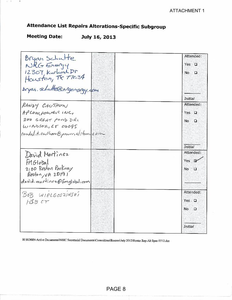
5. Review of the Roster (Attachment 1, pp. 5-8) 6. Action Items (Attachment 2, pp. 9-22)
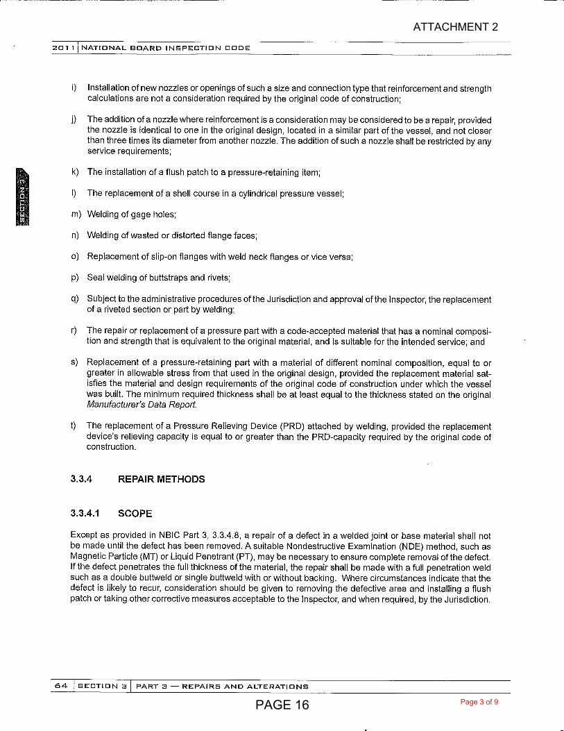
NB11-1001 Part 3, 3.3.4.9 SG R/A Specific - Tube plugging for fire tube boilers. Task Group members; A. Bramucci (Project Manager), W. Jones, and R. Miletti. (Attachment 2, p. 9)
July 2013 Mr. Bramucci gave a report and made a motion to approve the language in the attached proposal and the motion was unanimously approved.
NB12-0403 Part 3 R/A Specific CSEF Weld Repair Options using temper bead welding. Task Group
members; G. Galanes (Project Manager). (No attachment)
July 2013 A progress report was given by Mr. George Galanes.
NB12-0801 Part 3, SG R/A Specific - Repair and alteration of Gasketed PHEs in the field. Task Group
Project Manager – E. Ortman, J. Pillow, G. Galanes, B. Wielgoszinski. (Attachment 2, pp. 10-22)
July 2013 A progress report along with 3 documents for review was presented by Mr. Ed Ortman.
7. New Business (Attachment 3, pp. 23-81)
NB13-0502 Part 3, 2.5.3 e), SG R/A Specific - Clarify the wording in this section to state, “After the finished weld has reached ambient temperature and when required by the specific welding method, the surface temper bead reinforcement layer has been removed substantially flush with the surface of the base metal, the weld shall be examined again by either of the above methods to determine that no defects exist using acceptance standards acceptable to the Inspector or original code of construction. Task Group Project Manager – Jim Sekley. (No Attachment)
July 2013 A motion was made to approve the proposed language on the agenda attachment and after discussion, the motion was withdrawn and a TG of Jim Sekley will work on this item and report to the SG at the next meeting.
PAGE 2

IN13-0301 – SC on Repair and Alteration, – Question 1: Does Part 3, 3.2.2 c) prevent an "R" Certificate Holder with the capabilities within his shop from rolling and welding a shell or other such items as headers, nozzles,(flange to pipe) for replacement in a vessel or boiler has is repairing or altering? Brian Boseo and Bob Wielgoszinski agreed to work on this item and make recommendations to the SC R&A. (Attachment 3, pp. 23-24)
July 2013 The Subgroup worked on SC Interpretations with the intent of providing guidance to the Subcommittee. The subgroup unanimously endorsed the proposed language in the Attachment.
IN13-0401 – Part 3, 3.2.5, SC Repair and Alteration – Question 1: Is it the intent of the requirements in
paragraph 3.2.5 that calculations be both completed and also made available to the Inspector for review prior to the start of any physical work? (Attachment 3, pp.25-27)
July 2013 The Subgroup worked on the following SC Interpretations with the intent of providing guidance to the Subcommittee. The subgroup unanimously endorsed the proposed language in the Attachment.
IN13-0501 – Part 3, 3.3.3 and 3.4.2 SC Repairs and Alterations – Question: May a R and U Certificate
Holder make either a repair or an alteration to a pressure vessel by installing an new expansion joint, either over, or in place of an existing expansion joint that may have failed, or is damaged and may be expected to fail; by fabricating a new expansion joint as a U stamped Part in complete accordance with Section VIII Div. 1 Appendix 26,, then cutting this new Part into two pieces longitudinally so that it may be installed by field welding two new longitudinal welds without disassembly of the pressure vessel if:
a) the two new longitudinal welds are typed 1 per table UW-12. b) the installation does not permit radiographic examination, c) the backside of the weld is not accessible for either visual or penetrant examination, d) design calculations of these welds at .6 WJE are adequate to the existing design and, e) the vessel is satisfactorily hydrostatic tested at 1.3 times MAWP? Condition 1: A new expansion joint of a larger diameter will be installed over the existing joint. Condition 2: The old joint is removed and one of the same diameter will be installed in its place. Reply: Yes if acceptable to the Inspector and when required the Jurisdiction. Condition 1 being an alteration and Condition 2 being a repair. (Attachment 3, pp.)
July 2013 The Subgroup worked on SC Interpretations with the intent of providing guidance to the Subcommittee. The Subgroup reviewed this item and will recommend to the Subcommittee that a letter be sent to the inquirer stating the NBIC has no rules governing this activity and that a new Action Item will be created to address it. (Attachment 3, pp. 28-29)
ASME Section IX updates – (Attachment 3, pp. 30-81)
July 2013 A presentation was made by Mr. Walt Sperko concerning the ASME Section IX updates.
PAGE 3

8. Future Meetings January 13-16, 2014, San Antonio, TX July 14-17, 2014, Columbus, Ohio 9. Adjournment A motion was made to adjourn, and the meeting was adjourned at 4:15 P.M. Respectfully Submitted, James McGimpsey Secretary :rh
PAGE 4

PAGE 5
ATTACHMENT 1

PAGE 6
ATTACHMENT 1

PAGE 7
ATTACHMENT 1
PAGE 8
ATTACHMENT 1

Part 3 – Repairs and Alterations Page 77 Proposed Changes NB11-1001
Rational: An effort to address many jurisdictions and repair organizations concerns with the tube plugging of firetube boilers and procedures that are performed on a continuous basis and to assist in unifying basic requirements following guidelines of the NBIC. Tube plugging is presently being performed using various processes such as welding, and mechanical methods such as driving and expanding to existing tubes (sleeved or un-sleeved) or tube sheet holes when tubes are removed. The Task Group considered the scope of the NBIC should only address the repairs that pertain to replacement of tubing or when tubing involves welding in its repair method. The task group felt that the plugging of a tube or tubes in a firetube boiler is a deviation from its original operating parameters and the manufacturer’s original design. The NBIC should not address mechanical repair methods, and could not safely determine a repair procedure or process when the various effects on the pressure boundaries, heat transfer and byproducts of combustion are unknown. The Task Group endorse the use of should vs. shall as documented so cases where it is not necessary to consult the manufacturer, particularly if you have an experienced and knowledgeable R stamp holder who can make the necessary design considerations (both structural and performance related). The original Manufacturer may not even exist in some cases.
Section 3.3.4.9 TUBE PLUGGING IN FIRETUBE BOILERS
a) Plugging of firetubes in a firetube boiler is not recommended, but the practice is not prohibited. There may be cases where replacement of a firetube is not practical at the time a defective firetube is detected. In those cases, with acceptance of the Inspector and, when required, the Jurisdiction, the tube may be plugged. The boiler may be returned to service for a period of time agreed-upon by the Inspector and, when required, the Jurisdiction, at the end of which the tube shell be replaced.
b) The use of plugs held in place by mechanical means is
neither required nor prohibited, nor is the use of plugs held in place by welding required or prohibited.
c) Based on an evaluation by the “R” Certificate Holder
performing the repair and with acceptance by the Inspector and, when required, the Jurisdiction, plugs held in place by welding may be installed by welding the plug to the tube, to the tube sheet, or a combination of both.
d) Welding and material shall be in accordance with the
original code of construction or as noted in the applicable sections of the NBIC Part.
e) The Form R-1 shall be completed for plugging of firetubes
whether using plugs held in place by mechanical means or by welding.
Insert New Para. Here
NB11-1001 RA Specific Subgroup July 2013 Meeting Rev.B Page 1 of 1
PAGE 9
ATTACHMENT 2
eortman
Pencil
eortman
Text Box
shall
eortman
Text Box
eortman
Text Box
Plugs may be held in place by mechanical means or by welding.
eortman
Pencil
eortman
Text Box
the owner,
eortman
Pencil
eortman
Text Box
. The use of plugs held in place by mechanical means shall be noted in the remarks section of the Form R-1. The agreed upon duration before replacement of the plugged tube shall be noted in the remarks section of the Form R-1.
eortman
Pencil

NBIC Subcommittee R&A Action Block
Subject Gasketed Plate Heat Exchangers
File Number NB12-0801 Prop. on Pg. 1 thru 9
Proposed Revision Add examples of routine repairs, repairs, and alterations for gasketed plate heat exchangers and revise R-1 form to include gasketed PHEs.
Statement of Need
Because of the unique design of the PHE, the current ASME Pressure Vessel and NBIC Codes do not specifically address the design of PHE’s, nor the potential repairs or alterations. This is intended to provide guidance to the industry and the Jurisdictions.
Project Manager Ed Ortman
SubGroup R&A Specific
SubGroup Negatives
SG Meeting Date July 16, 2013
SubCommittee Negatives
SC Meeting Date July 17, 2013
PAGE 10
ATTACHMENT 2

Repairs and Alterations of Gasketed PHE’s in the Field
By Mike Pischke
7/1/13
Introduction
This is intended to describe the current common industry practices of Plate Heat Exchanger (PHE) users
regarding their operation, routine repairs and alterations. Because of the unique design of the PHE, the
current ASME Pressure Vessel or NBIC Codes do not specifically address the design of PHE’s, nor the
potential alterations. The typical industries include, but not limited to the Power, Petrochemical,
Maritime, HVAC, Bio‐Pharmaceutical , and Food production.
Expansion and Contraction of Plate Packs
One of the primary benefits of the gasketed PHE is that the heating surface can be expanded or
contracted in response to changes in fluid flow, process parameters, and/or ambient temperature
variations. The plate packs are expanded or reduced due to the increase or decrease in heat transfer
requirements, respectively. Also, because turbulence is necessary for effective heat transfer, the
quantity of heat transfer plates are critical to ensure the proper flow rates and pressure drops during
operation. This is adjusted by adding or subtracting the number of heat transfer plates. Users will
often also add plates gradually as production demands are incrementally increased. This avoids the
need for repeated and costly replacement of entire heat exchangers. They will also adjust the number
based on seasonal temperature variations.
Code Implications: Although the Code does not specifically address the addition or removal of heat
transfer plates, this has indirect Code implications. Adding or subtracting plates in no way affects the
specific design parameters of Pressure and Temperature, but does change the volume of the heat
exchanger and the heat transfer surface area. Unless someone counts every single plate in a PHE and
compares it to the number listed on the Data Report, it would not be obvious that a change was made.
Gasket Replacement
The expected life of gaskets within a PHE plate pack may vary from one year to decades; based upon the
gasket material selection, process fluid(s), operating parameters, and environmental conditions.
Ideally, the gasket replacement coincides with the routine cleaning of the heat transfer plates. At this
time, the entire plate pack is removed from the frame, the gaskets removed from the plates, then the
plates are mechanically and/or chemically cleaned. The cleaned plates are then re‐gasketed using new
gaskets. Glued gaskets are typically removed using liquid nitrogen prior to cleaning. After re‐gasketing,
the plate pack is returned to the frame and typically hydrostatically or pneumatically tested at the
MAWP.
PAGE 11
ATTACHMENT 2

Code Implications: Although the ASME Code does not directly address gaskets or gasket materials, the
practical operating parameters are typically limited by the gasket material. Maximum operating
temperatures are determined by the degradation rate of the gasket material, and the MAWP set by an
adjusted test pressure when the particular gasket‐heat transfer plate combination will begin to leak.
Heat Transfer Plate Replacement
Under normal operating conditions, heat transfer plates should last for decades in service. Heat
transfer plates typically need to be replaced due to deformation from opening and closing, corrosion,
fatigue, and/or fouling. When being replaced, they may be replaced using plates from a different
manufacturer and even a different material from the original Code stamped unit. For example, if the
original plates were made from 0.4mm thick, 304 stainless steel and they corroded over time due to
chloride attacks, the user may choose to replace the corroded plates with something more resistant.
Perhaps they would replace these plates with 316L plates and even increase the thickness to 0.5mm.
This is a common practice.
Another common practice is to have multiple, identical PHE’s in a chemical production facility and rotate
out spare plate packs as the glued gaskets break down and need to be replaced over time. Spare plate
packs with glued gaskets are kept in stock at the facility, waiting to be swapped out with the plates in
production. This allows the chemical company’s maintenance personnel to swap out a plate pack during
a brief shut down period. The removed plate pack is re‐conditioned by cleaning, removing the gaskets
and gluing on new gaskets. These plate packs now become the new spares. This allows them to re‐use
the heat transfer plates which are often made from expensive materials such as nickel alloys, or
titanium.
Code Implications: Heat Transfer plates and laser welded cassettes are considered UG‐11 “Standard
Pressure Parts” per Interpretations VIII‐1‐89‐236 and VIII‐1‐95‐21. There is also an Interpretation (VIII‐
81‐89R) that allows the heat transfer plates to be made from non‐Code material. Beyond these
Interpretations, there are no rules regarding the material of the heat transfer plates. Because the heat
transfer plates are contained between the frame plates, the strength of the PHE relies on the bolts and
frame plates and never the strength of the heat transfer plates.
PAGE 12
ATTACHMENT 2

Proposed Guidelines
Does Not Affect Routine Repair Repair (R‐Stamp) Alteration (R‐Stamp)
Minor addition or removal of Heat
Transfer Plates within the range specified on
the U‐1P.
Removal and replacement of Heat
Transfer Plates, identical to those
specified in the U‐1P.
Weld Repair of any pressure part. (e.g. Nozzle replacement.)
A change in Heat Transfer Plate material.
A change in the gasket material.
Removal and replacement of the
Tightening Bolts with in‐kind replacement.
The in‐kind replacement of the Frame or Pressure
Plates.
A change in the thickness of the Heat
Transfer Plates
Removal, cleaning and replacement of the
plate pack.
A change in the welded attachments. (e.g. welded feet.)
A change in the Tightening Bolt material
grade or type.
A change in the bolted attachments. (e.g.
bolted feet.)
A change in the diameter of Tightening
Bolt material
A change in the material and/or
thickness of the Frame or Pressure Plates.
PAGE 13
ATTACHMENT 2

Page 1 of 9PAGE 14
ATTACHMENT 2
eortman
Text Box
FOR INFO ONLY
eortman
Text Box
NB12-0801 July 16 2013

Page 2 of 9PAGE 15
ATTACHMENT 2
eortman
Text Box
NB12-0801 July 16 2013
eortman
Text Box
5) The following on gasketed plate heat exchangers: i) Removal and replacement of heat transfer plates identical to those listed on the Manufacturer's Data Report; ii) In kind replacement of tightening bolts; iii) A change in welded attachments (e.g. welded feet).
eortman
Pencil
Page 3 of 9PAGE 16
ATTACHMENT 2
eortman
Text Box
NB12-0801 July 16 2013
eortman
Text Box
u) In a gasketed plate heat exchanger: 1) Weld repair of any pressure part (e.g. nozzle repair or in kind replacement of nozzle); 2) In kind replacement of frame or pressure plates.
eortman
Pencil

Page 4 of 9PAGE 17
ATTACHMENT 2
eortman
Text Box
NB12-0801 July 16 2013
eortman
Text Box
FOR INFO ONLY

Page 5 of 9PAGE 18
ATTACHMENT 2
eortman
Text Box
NB12-0801 July 16 2013
eortman
Text Box
k) The following on gasketed plate heat exchangers: a) A change in heat transfer plate material; b) A change in thickness of heat transfer plates; c) A change in tightening bolt material or grade; d) A change in tightening bolt diameter e) A change in the material or thickness of the frame plate of pressure plates.
eortman
Pencil

Page 6 of 9PAGE 19
ATTACHMENT 2
eortman
Text Box
NB12-0801 July 16 2013
eortman
Text Box
Gasketed Plate Heat Exchanger
eortman
Rectangle
eortman
Pencil
eortman
Text Box
Note to Editor: Add as part of line 7

Page 7 of 9PAGE 20
ATTACHMENT 2
eortman
Text Box
NB12-0801 July 16 2013
eortman
Text Box
FOR INFO ONLY

Page 8 of 9PAGE 21
ATTACHMENT 2
eortman
Text Box
NB12-0801 July 16 2013
eortman
Text Box
FOR INFO ONLY

Page 9 of 9PAGE 22
ATTACHMENT 2
eortman
Text Box
NB12-0801 July 16 2013
eortman
Pencil
eortman
Pencil
eortman
Text Box
, or gasketed plate heat exchanger.

Revised voted by SG‐RA Specific: IN13‐301 Question: An “R” Certificate Holder is performing a repair on an ASME stamped vessel in the field. To better manage the welding and fabrication work, the “R” Certificate Holder chooses to prefabricate some of the parts in the shop for ultimate use in the field on the vessel being repaired. Does the NBIC that these shop fabricated parts be ASME Code stamped? Reply: No, Part 3‐3.2.2 c) applies to parts that are fabricated by organizations other than the R stamp holder for repairs or alterations on which he is working. Proposed new item: In addition propose revised words in the code, additional a new second paragraph to be added to 3.2.2 c). ASME stamping and completion of an ASME Manufacturer’s Partial Data Report is not required for parts fabricated by the “R” Certificate Holder that will be used on pressure retaining items being repaired or altered by the same “R” Certificate Holder. The method of identification, transfer, and receipt of parts shall be described in the quality control system. SG‐RA Specific vote: 1 negative by Ortman
BACKGROUND INFORMATION ONLY:
IN13‐0301 Part 3, 3.2.2 c) SC 011 Repair and Alteration. This inquiry is of interest to Eastman since we have the capability to build our own parts for repairs:
o Subcommittee Repairs and Alterations Action: Move the interpretation with alternate question and reply.
Question: An “R” Certificate Holder is performing a repair on an ASME stamped vessel in the field. To better manage the welding and fabrication work, the “R” Certificate Holder chooses to prefabricate some of the parts in the shop for ultimate use in the field on the vessel being repaired. Are these shop fabricated parts required to be ASME Code stamped and inspected by an Authorized Inspector? Reply: No, Part 3‐3.2.2 c) is meant for parts that are fabricated by organizations other than the R stamp holder for repairs or alterations on which he is working. Motion PASSED. In addition propose revised words in the code, additional paragraph to be added to 3.2.2 c) ASME stamping and completion of an ASME data report is not required for parts fabricated by the “R” Certificate Holder that will be used on pressure retaining items being repaired or altered by the same “R” Certificate Holder. The controls for this activity shall be described in the quality control system. Motion PASSED.
o NBIC Main Committee Action: Prepare a new question and reply and Code revision. Progress report
PAGE 23
ATTACHMENT 3

IN13‐0301
I vote negative on this item because I thing question and reply 1 in interpretation 98‐28 makes it clear
that it was never the intent that an R certificate holder could fabricate parts.
PAGE 24
ATTACHMENT 3

PROPOSED INTERPRETATION
Inquiry No. IN13-0401
Source
Jeremy Napier
Subject
Part 3, 3.2.5
Edition
2011 Edition
Question
Q1: Is it the intent of the requirements in paragraph 3.2.5 that calculations be both completed and also made available to the Inspector for review prior to the start of any physical work? Q2: Does the requirement in paragraph 3.2.5 that calculations be completed prior to the start of any physical work, also mean that the calculations must be completed prior to the start of any physical work related to fabrication of replacement parts (as defined in paragraph 3.2.2c) that will be used in the alteration? Q3: Is it the intent that the organization that completes the design calculation as required by paragraph 3.2.5 be an "R" Certificate Holder? Q4: If an alteration involves the installation of a replacement part (as defined in Paragraph 3.2.2 c) that has been designed, fabricated, inspected and stamped in accordance with the original code of construction and for which the part fabricator has documented on the partial data report that they have certified the design of the part for a specific set of design conditions (MAWP,MAWT, MDMT, corrosion allowance, etc.), must the "R" Certificate Holder responsible for executing the Design Certification on the R-2 Form obtain the calculations from the part fabricator and make available for review by the Inspector?
Reply
A1: Yes
A2: No
A3: No; however the R-Certificate holder responsible for executing the "Design Certification" portion of the R-2 Form, must assure himself that the design complies with the NBIC and by signing; the Design Certification accepts responsibility for the design.
Alternate Proposed Reply Q3: Yes, "the organization" in paragraph 3.2.5 refers to the "R" Certificate holder responsible for preparing and executing "Design Certification" portion of the R-2 Form. This does not preclude the "R" Certificate Holder from having the calculations prepared or otherwise obtaining the calculations from others, but the "R" Certificate holder must assure himself that the design complies with the NBIC and by signing the
PAGE 25
ATTACHMENT 3
Design Certification accepts responsibility for the design.
A4: No, however the "R" Certificate holder responsible for executing the Design Certification must assure that the design conditions certified for the new part are consistent with the original vessel design conditions. Additionally the R Certificate holder would be responsible for assessing whether the installation of the new part impacted in any manner the existing components in the overall vessel design and for completing any calculations that might be required to address such impact.
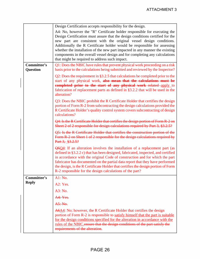
Committee’s Question
Q1: Does the NBIC have rules that prevent physical work proceeding on a risk basis prior to the calculations being submitted and reviewed by the Inspector?
Q2: Does the requirement in §3.2.5 that calculations be completed prior to the start of any physical work, also mean that the calculations must be completed prior to the start of any physical work related apply to fabrication of replacement parts as defined in §3.2.2 that will be used in the alteration?
Q3: Does the NBIC prohibit the R Certificate Holder that certifies the design portion of Form R-2 from subcontracting the design calculations provided the R Certificate Holder’s quality control system covers subcontracting of design calculations?
Q4: Is the R Certificate Holder that certifies the design portion of Form R-2 on Sheet 2 of 2 responsible for design calculations required by Part 3, §3.2.5?
Q5: Is the R Certificate Holder that certifies the construction portion of the Form R-2 on Sheet 1 of 2 responsible for the design calculations required by Part 3, §3.2.5?
Q6Q4: If an alteration involves the installation of a replacement part (as defined in §3.2.2 c) that has been designed, fabricated, inspected, and certified in accordance with the original Code of construction and for which the part fabricator has documented on the partial data report that they have performed the design, is the R Certificate Holder that certifies the design portion of Form R-2 responsible for the design calculations of the part?
Committee’s Reply
A1: No.
A2: Yes.
A3: No.
A4: Yes.
A5: No.
A6A4: No; however, the R Certificate Holder that certifies the design portion of Form R-2 is responsible to satisfy himself that the part is suitable for the design conditions specified for the alteration in accordance with the rules of the NBIC.ensure that the design conditions of the part satisfy the requirements of the alteration.
PAGE 26
ATTACHMENT 3

Rationale
A1 & A2: Due to circumstances such as shop and field scheduling restrictions, it is not unusual for it to be necessary that work proceed on a risk basis. To establish rules that would prevent this option could have a negative impact with little or no compensating positive impact.
SC Vote
Unanimous No. Affirmative No. Negative No. Abstain No. Not Voting
NBIC Vote
Unanimous No. Affirmative No. Negative No. Abstain No. Not Voting
Negative Vote
Comments
PAGE 27
ATTACHMENT 3

NB14‐0203 result of IN13‐0501
Action Item Request Form
8.3 CODE REVISIONS OR ADDITIONS
Request for Code revisions or additions shall provide the following:
a) Proposed Revisions or Additions
For revisions, identify the rules of the Code that require revision and submit a copy of the appropriate
rules as they appear in the Code, marked up with the proposed revision. For additions, provide the
recommended wording referenced to the existing Code rules.
Existing Text:
b) Statement of Need
Provide a brief explanation of the need for the revision or addition.
None
IN13‐0501 generated this request for a new Action Item as the NBIC did not address the inquirer’s
question. The new Action item is NB13‐03 Encapsulation RA Specific
Task Group assigned at SC RA‐Brian Boseo‐PM, Bob Wielgoszinski, Bryan Schulte and George Galanes
J McGimpsey‐ Secretary Part 3 RA
PAGE 28
ATTACHMENT 3

NB14‐0203 result of IN13‐0501
c) Background Information
Provide background information to support the revision or addition, including any data or changes in
technology that form the basis for the request that will allow the Committee to adequately evaluate the
proposed revision or addition. Sketches, tables, figures, and graphs should be submitted as appropriate.
When applicable, identify any pertinent paragraph in the Code that would be affected by the revision or
addition and identify paragraphs in the Code that reference the paragraphs that are to be revised or
added.
PAGE 29
ATTACHMENT 3
RHeilman
Text Box
NB14-0701

2013 Update to ASME Section IX
Prepared by Walter J. Sperko, PE Sperko Engineering
Greensboro, NC 27406 www.sperkoengineering.com
PAGE 30
ATTACHMENT 3

BIG CHANGES • Addition of a new Part QF,
Plastic Fusion • Creation of Part QG, General
Requirements. • Charter and Scope
PAGE 31
ATTACHMENT 3

Scope of BPV IX To establish specifications for welding and brazing consumables for publication in Section II, Part C of the Boiler and Pressure Vessel Code. To establish requirements for qualification of welders, welding operators, brazers, brazing operators, plastic fusing machine operators and the procedures they employ in welding, brazing and plastic fusing for publication in Section IX of the Boiler and Pressure Vessel Code. These requirements are intended for use in the sections of the Boiler and Pressure Vessel Code covering construction and in-service integrity of components and items, and for use in the B31 Code for Pressure Piping to the extent that they are referenced in those documents. This committee shall also advise on welding, brazing and plastic fusing rules that are proposed for construction and in-service integrity in the Boiler and Pressure Vessel and the B31 Code.
PAGE 32
ATTACHMENT 3

PLASTIC FUSION All fusing is done using a machine
PAGE 33
ATTACHMENT 3

“A” Minimum Melt Bead Size is Required Prior to Heater Removal
PAGE 34
ATTACHMENT 3

Minimum Bead Size and time limit between plate removal and pressing together vary with pipe size
PAGE 35
ATTACHMENT 3

Fusing QF-131 Data Acquisition Record Requirements The following fusing variables shall be recorded for each fused test joint: (a) heater surface temperature immediately before inserting the heater plate (b) gauge pressure during the initial heat cycle (c) gauge pressure and elapsed time during the heat-soak cycle (d) heater removal (dwell) time (e) gauge pressure and elapsed time during the fusing/cool cycle (f) drag pressure (g) joint configuration (h) pipe diameter and wall thickness (i) type of HDPE material (Specification and Classification) and manufacturer (j) FPS used, operator identification, time, date, fusing machine identification
PAGE 36
ATTACHMENT 3

Testing
QF-143 Bend Tests – Guided Bend Test – The usual – Reverse Bend test
PAGE 37
ATTACHMENT 3

Testing
• QF-144 High Speed Tensile Impact Test This test method is designed to impart tensile impact energy to a butt fused PE pipe specimen to evaluate its ductility.
• High speed is 4 to 6 in/sec.
PAGE 38
ATTACHMENT 3

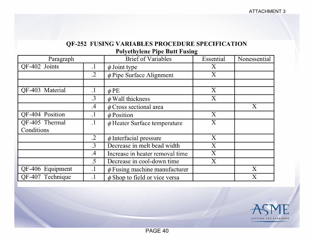
• QF-200.1.1 Fusing Procedure Specification (FPS) A FPS is a written qualified fusing procedure prepared to provide direction to the fusing machine operator for making production fused joints.
• Contents of the FPS. The completed FPS shall address all of the essential and nonessential variables for each fusing process used in the FPS. The essential and nonessential variables for fusing are listed in QF-252.
PAGE 39
ATTACHMENT 3
PAGE 40
ATTACHMENT 3

Standard Fusing Procedure Specification (SFPS) A fusing procedure specification that contains acceptable polyethylene fusing variables based on standard industry practice and testing as reported in the Plastic Pipe Institute (PPI), Report TR-33-06 or ASTM F2620-09 Standard Practice for Heat Fusion Joining of Polyethylene Pipe and Fittings. A SFPS may be used for production fusing by manufacturers or contractors without further qualification.
PAGE 41
ATTACHMENT 3

Fusing Operator Qualification
PAGE 42
ATTACHMENT 3

Part QG General Requirements QW-100.3 currently says: • QW-100.3 Welding Procedure Specifications
(WPS) written and qualified in accordance with the rules of this Section, and welders and welding operators of automatic and machine welding equipment also qualified in accordance with these rules may be used in any construction built to the requirements of the ASME Boiler and Pressure Vessel Code or the ASME B31 Code for Pressure Piping.
PAGE 43
ATTACHMENT 3

Part QG General Requirements QB-100.3 currently says: • QW-100.3 Brazing Procedure Specifications
(BPS) written and qualified in accordance with the rules of this Section, and brazers and operators of automatic and machine brazing equipment also qualified in accordance with these rules may be used in any construction built to the requirements of the ASME Boiler and Pressure Vessel Code or the ASME B31 Code for Pressure Piping.
PAGE 44
ATTACHMENT 3

Part QG General Requirements QF-100.3 would have said: • QW-100.3 Fusing Procedure Specifications
(FPS) written and qualified in accordance with the rules of this Section, and fusing operators of machine welding equipment also qualified in accordance with these rules may be used in any construction built to the requirements of the ASME Boiler and Pressure Vessel Code or the ASME B31 Code for Pressure Piping.
PAGE 45
ATTACHMENT 3
Part QG General Requirements Instead of repeating this again, QG-101 says: • Procedure specifications written and qualified
in accordance with the rules of this Section and personnel whose performance has been qualified to use the procedure specification in accordance with these rules may be used to construct components which comply with the requirements of the ASME Boiler and Pressure Vessel Code or the ASME B31 Codes for Pressure Piping.
• Corresponding words in QW and QB are deleted
PAGE 46
ATTACHMENT 3

Part QG General Requirements • There was some consolidation/elimination of
redundancy in the requirements. • No changes to administrative aspects
(responsibility for qualification by each organization, use of current edition for new qualifications/old qualifications still valid, etc.)
• The definitions were moved from QW-492 to QG-109
• Repetition of “manufacturer or contractor” was eliminated by defining “organization”
PAGE 47
ATTACHMENT 3

Part QG General Requirements • NOTE: An organization, as used in this
Section, is a manufacturer, contractor, assembler, installer, or some other single or combined entity having responsibility for operational control of the material joining methods used in the construction of components in accordance with the Codes, standards and specifications which reference this Section.
• Operational Control = Direct Supervision
PAGE 48
ATTACHMENT 3
• Hybrid Laser GMAW Welding • Hybrid Plasma GMAW • Friction Stir Welding
PAGE 49
ATTACHMENT 3
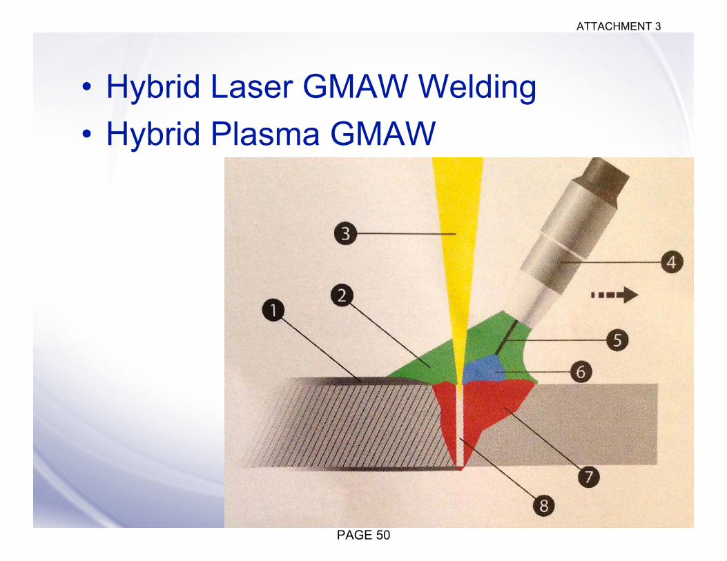
• Hybrid Laser GMAW Welding • Hybrid Plasma GMAW
PAGE 50
ATTACHMENT 3

PAGE 51
ATTACHMENT 3

• Hybrid Laser GMAW Welding
• Hybrid Plasma GMAW
Picture courtesy of Fronius
PAGE 52
ATTACHMENT 3

• Welding, Hybrid: welding in which two or more welding processes are used in the same weld pool.
• Welding, Hybrid, Process Sequence: the order of each welding process with respect to direction of travel.
• Welding, Hybrid, Process Separation: the distance between each welding process as specified in the WPS.
PAGE 53
ATTACHMENT 3

• Friction Stir Welding
PAGE 54
ATTACHMENT 3

• Friction Stir Welding
PAGE 55
ATTACHMENT 3

Welding Filler Metal Revision
PAGE 56
ATTACHMENT 3

Welding Filler Metal Revision
• SFA-5.21/SFA-5.21M, Electrogas Welding Filler Metals
• SFA-5.14/SFA-5.14M, Nickel Alloy Welding Electrodes
• SFA5.23/SFA5.23M:2011 Low Alloy Steel Submerged Arc Welding Fluxes and Electrodes
• AWS A5.12M/A5.12:2009 (ISO 6848:2004 MOD) Tungsten Electrodes (errata)
PAGE 57
ATTACHMENT 3

Welding Filler Metals
• SFA5.8/SFA5.8M:2011 Filler Metals for Brazing and Braze Welding
• SFA5.36/SFA5.36M:2012, Carbon and Low-Alloy Steel Flux Cored Electrodes and Metal Cored Electrodes for Gas Metal Arc Welding – SFA 5.20 Carbon Steel Flux Cored Electrodes – SFA 5.29 Low Alloy Flux Cored Electrodes
• Rejected A5.32 (ISO 14175), Shielding Gas – Concern over increase in purity – Concern over increase in dew point
PAGE 58
ATTACHMENT 3

Base Metals
The 2011 Addenda loosened the range of materials to which Section IX would consider assigning P-Numbers • 172 new line entries were added, including
differentiation by thickness/min. tensile. • 20 new ASME specs (39 grades) • 12 new ASTM specs (19 grades) • API 5L (79 new grades) • 5 new foreign specs (16 grades)
PAGE 59
ATTACHMENT 3

Base Metals
Additionally, 195 line entries (grades) were revised (96 of those were corrected by errata).
LISTING FORMAT REVISED
Listing format revised to show A/SA-XXX and B/SB-XXX eliminating the question/issue of ASTM versions of ASME specifications not being assigned P-numbers
PAGE 60
ATTACHMENT 3

Temper Bead Welding
• Hardness measurement locations for temper bead qualifications fixed.
PAGE 61
ATTACHMENT 3

PAGE 62
ATTACHMENT 3

PAGE 63
ATTACHMENT 3

Temper Bead Welding
• TWI LLC report developing hardness acceptance criteria for temper bead welding qualifications is completed. IIT testing being done by University of Seoul.
• Instrumented Indentation Testing (IIT) permitted for Temper Bead Welding
PAGE 64
ATTACHMENT 3

Welding to Corrosion-Resistant Overlay • QW-424.2 For welds joining base metals
to weld metal buildup or corrosion-resistant weld metal overlay, the buildup or overlay portion of the joint may be substituted in the test coupon by any P-Number base material that nominally matches the chemical analysis of the buildup or overlay.
PAGE 65
ATTACHMENT 3
Fillet welds and impact testing
• QW-202.2(c) Any groove weld qualification qualifies all fillet welds in accordance with QW-452.4
PAGE 66
ATTACHMENT 3

Fillet welds and impact testing
PAGE 67
ATTACHMENT 3

Fillet welds and impact testing
GENERAL NOTE: Supplementary essential variables apply when notch toughness is required by other Sections. • QW-403.6 The minimum base metal
thickness qualified is the thickness of the test coupon T or 5⁄8 in. (16 mm), whichever is less.
• QW-410.9 A change from multipass per side to single pass per side.
PAGE 68
ATTACHMENT 3

Welding the whole test coupon
PAGE 69
ATTACHMENT 3
Welding the whole test coupon
• (6) For test coupons over 6 in. (150 mm) thick, the full thickness of the test coupon shall be welded.
PAGE 70
ATTACHMENT 3

Stud Welding
• Conflict between QW-409.8 which allowed amperage to be changed at will; QW-410.10 limited amperage to ±10%.
• ±10% won out – QW-409.8 was deleted from the table of variables. Current type and polarity was move from nonessential to essential.
PAGE 71
ATTACHMENT 3

Tension Testing
PAGE 72
ATTACHMENT 3
Tension Testing
New footnote: • (e) When the diameter, D, of the reduced
section is measured and the actual value is used to calculate the tensile stress, specimens of nominal diameters other than those shown above may be used.
PAGE 73
ATTACHMENT 3

Tube to Tubesheet
QW-193.1 Procedure Qualification Specimens. . . . The thickness of the mockup tubesheet shall be at least as thick as the tubesheet, but is not required to be thicker than 2 in. (50 mm) and the cladding may be represented by base material of essentially equivalent chemical composition to the cladding composition.
PAGE 74
ATTACHMENT 3

Welding Operators
• Code case for qualifying welding operators by sectioning and etching of mockups when the welding equipment does not produce parts that can be radiographed or bend tested.
PAGE 75
ATTACHMENT 3

Volumetric Examination QW-302.2 Volumetric NDE. When the welder or welding operator is qualified by volumetric NDE, as permitted in QW-304 for welders and QW-305 for welding operators, the minimum length of coupon(s) to be examined shall be 6 in. (150 mm) and shall include the entire weld circumference for pipe(s) except that for small diameter pipe, multiple coupons of the same diameter pipe may be required, but the number need not exceed four consecutively made test coupons. The examination technique and acceptance criteria shall be in accordance with QW-191.
PAGE 76
ATTACHMENT 3

Brazing
• QB-410.5 A change from manual to machine or semi-automatic torch brazing, and vice versa.
PAGE 77
ATTACHMENT 3

Appendix K
• GUIDANCE ON INVOKING SECTION IX REQUIREMENTS IN OTHER CODES, STANDARDS, SPECIFICATIONS AND CONTRACT DOCUMENTS
• When another standard refers to Section IX, what do they need to specify (since Section IX only covers qualification. . . )
PAGE 78
ATTACHMENT 3

White Paper • “Auditing Welding Under ASME Section
IX” written for guidance of ASME and NB auditors
• When Section IX says each variable has to be addressed, what does that mean. – Each one has to be addressed – Some are conditional or can be addressed
by other variables • What should an auditor look for • Posted on BPV IX Home Page
PAGE 79
ATTACHMENT 3

Written Summary
• Will be published in the October 2013 welding Journal and posted at www.Sperkoengineering.com
• Previous summaries also posted there • Welding Positions Decoded (powerpoint) • White paper on the benefits to supporting
company supporting participation in voluntary standards committees.
PAGE 80
ATTACHMENT 3
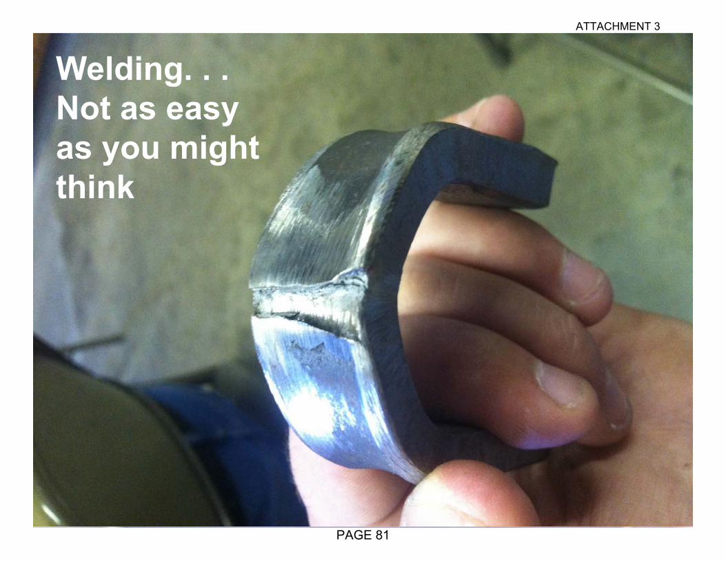
Welding. . . Not as easy as you might think
PAGE 81
ATTACHMENT 3