SUBCHAPTER C: CONVENTIONAL COLLECTION SYSTEMS
49
Texas Commission on Environmental Quality Page 1 Chapter 217 - Design Criteria for Domestic Wastewater Systems SUBCHAPTER C: CONVENTIONAL COLLECTION SYSTEMS §§217.51 - 217.71 Effective December 4, 2015 §217.51. Applicability. This subchapter applies to the design, construction, operation, maintenance, and testing of conventional gravity collection systems, conventional wastewater lift stations, force mains for wastewater transport, and reclaimed water conveyance systems. Adopted November 4, 2015 Effective December 4, 2015 §217.52. Edwards Aquifer. An owner who plans to install a collection system located over the Edwards Aquifer recharge zone, as defined in §213.3 of this title (relating to Definitions), must design and install the collection system in accordance with Chapter 213 of this title (relating to Edwards Aquifer), in addition to this subchapter. Adopted November 4, 2015 Effective December 4, 2015 §217.53. Pipe Design. (a) Flow Design Basis. An owner must use the requirements of this section to design a gravity collection system. (1) A collection system must be designed to transport the peak flow from the service area, plus infiltration and inflow. The design must minimize inflow and infiltration. Flow calculations must be included in the engineering report. (2) The flow calculations must include the details of the average flow, the flow peaking factor, and the infiltration and inflow. (3) The flow calculations must include the flow expected in the wastewater treatment facility immediately upon completion of construction and at the end of a 50- year period following construction. (b) Gravity Pipe Materials. (1) An owner must identify in the engineering report the proposed gravity collection system pipe with its appropriate American Society for Testing and Materials (ASTM), American National Standards Institute (ANSI), or American Water Works
Transcript of SUBCHAPTER C: CONVENTIONAL COLLECTION SYSTEMS

Texas Commission on Environmental Quality Page 1 Chapter 217 - Design Criteria for Domestic Wastewater Systems
SUBCHAPTER C: CONVENTIONAL COLLECTION SYSTEMS §§217.51 - 217.71
Effective December 4, 2015
§217.51. Applicability.
This subchapter applies to the design, construction, operation, maintenance, and testing of conventional gravity collection systems, conventional wastewater lift stations, force mains for wastewater transport, and reclaimed water conveyance systems.
Adopted November 4, 2015 Effective December 4, 2015 §217.52. Edwards Aquifer.
An owner who plans to install a collection system located over the Edwards Aquifer recharge zone, as defined in §213.3 of this title (relating to Definitions), must design and install the collection system in accordance with Chapter 213 of this title (relating to Edwards Aquifer), in addition to this subchapter.
Adopted November 4, 2015 Effective December 4, 2015 §217.53. Pipe Design.
(a) Flow Design Basis. An owner must use the requirements of this section to design a gravity collection system.
(1) A collection system must be designed to transport the peak flow from
the service area, plus infiltration and inflow. The design must minimize inflow and infiltration. Flow calculations must be included in the engineering report.
(2) The flow calculations must include the details of the average flow, the
flow peaking factor, and the infiltration and inflow. (3) The flow calculations must include the flow expected in the wastewater
treatment facility immediately upon completion of construction and at the end of a 50-year period following construction.
(b) Gravity Pipe Materials.
(1) An owner must identify in the engineering report the proposed gravity collection system pipe with its appropriate American Society for Testing and Materials (ASTM), American National Standards Institute (ANSI), or American Water Works

Texas Commission on Environmental Quality Page 2 Chapter 217 - Design Criteria for Domestic Wastewater Systems Association (AWWA) standard numbers for both quality control (dimensions, tolerances, pipe stiffness, dimensional ratio, etc.) and installation (bedding, backfill, etc.).
(2) The selection of gravity collection system pipes must be based on:
(A) the characteristics of the wastewater conveyed; (B) the possibility of septic conditions; (C) the ability to minimize inflow and infiltration; (D) any external forces; (E) any groundwater conditions; (F) the internal pressures; and (G) the abrasion and corrosion resistance of the pipe material.
(c) Joints for Gravity Pipes.
(1) The specifications for joints for gravity pipes must include the materials and methods used in making joints.
(2) Materials used for gravity pipe joints must prevent inflow, infiltration,
and root entrance. A joint must:
(A) include rubber gaskets; (B) include polyvinyl chloride (PVC) compression joints; (C) include high density polyethylene compression joints; (D) be welded; or (E) be heat fused.
(3) The specifications must include ASTM, AWWA, ANSI, or other appropriate national reference standards for the pipe joints.
(d) Separation Distances.

Texas Commission on Environmental Quality Page 3 Chapter 217 - Design Criteria for Domestic Wastewater Systems
(1) Collection system pipes must be installed in trenches separate from water supply trenches.
(2) Wherever possible, a collection system pipe must be located below a
water supply pipe. If a collection system pipe cannot be located below a water supply pipe, the owner must justify in the engineering report why it is not possible to locate the collection system pipe below the public water supply pipe.
(3) Wherever possible, collection system pipes and manholes must be
located at least nine feet from all water supply pipes. If a collection system pipe or manhole cannot be located at least nine feet away from a water supply pipe, the owner must justify in the engineering report why it is not possible to provide at least nine feet of separation. Table C.1. in Figure: 30 TAC §217.53(d)(3) provides a reference to paragraphs in this subsection that apply if a collection system pipe or manhole cannot be located at least nine feet away from a water supply pipe.
Figure: 30 TAC §217.53(d)(3)
Table C.1.
Case Protection Requirement
Parallel pipes within nine feet, where the collection system pipe is above the water supply pipe
Encased in a casing pipe according to paragraph (4) of this subsection
Crossing pipes within nine feet, where the collection system pipe is above the water supply pipe
Encased in a casing pipe according to paragraph (5)(A) of this subsection
-or- Constructed using 150 per square inch (psi) pressure class pipe according to paragraph (5)(B) of this subsection
Parallel pipes within nine feet, where the collection system pipe is below the water supply pipe
Constructed using 150 psi pressure class pipe according to paragraph (6)(A) of this subsection
-or- Encased in a casing pipe according to paragraph (6)(B) of this subsection
Crossing pipes within nine feet, where the collection system pipe is below the water supply pipe
Constructed using 150 psi pressure class pipe according to paragraph (7)(A) of this subsection

Texas Commission on Environmental Quality Page 4 Chapter 217 - Design Criteria for Domestic Wastewater Systems
-or- Encased in cement-stabilized sand according to paragraph (7)(B) of this subsection
-or- Encased in a casing pipe according to paragraph (7)(C) of this subsection
Manhole within nine feet of a water supply pipe
No measurable leakage according to paragraph (8)(A) of this subsection
-or- Encased in cement-stabilized sand according to paragraph (8)(B) of this subsection
(4) If a collection system pipe is located above a water supply pipe and
runs parallel to the water supply pipe, each portion of the collection system pipe within nine feet of the water supply pipe must be encased. The casing pipe must be constructed of at least 150 per square inch (psi) pressure class pipe that:
(A) encases the entire length of collection system pipe that is within
nine feet of the water supply pipe;
(B) is sealed at both ends with cement grout or a manufactured seal;
(C) is at least two nominal sizes larger than the wastewater
collection pipe; and (D) is supported by spacers between the collection system pipe and
the encasing pipe at a maximum of five-foot intervals. (5) If a collection system pipe crosses above a water supply pipe, each
portion of the collection system pipe within nine feet of the water supply pipe must either be encased in a casing pipe according to subparagraph (A) of this paragraph, or must be constructed using at least 150 psi pressure class pipe according to subparagraph (B) of this paragraph.
(A) A casing pipe for a collection system pipe that crosses above a
water supply pipe must be constructed of at least 150 psi pressure class pipe that is:
(i) sealed at both ends with cement grout or a manufactured seal;

Texas Commission on Environmental Quality Page 5 Chapter 217 - Design Criteria for Domestic Wastewater Systems
(ii) at least two nominal sizes larger than the wastewater collection pipe; and
(iii) supported by spacers between the collection system pipe
and the encasing pipe at a maximum of five-foot intervals.
(B) A collection system pipe that crosses above a water supply pipe must be constructed of at least 150 psi pressure class, corrosion-resistant, non-brittle pipe and must use manufacturer-approved adapters. Gasketed joints, compression joints, and other non-bonded joints must be designed to seal at atmospheric pressure.
(6) If a collection system pipe is located below a water supply pipe and
runs parallel to the water supply pipe, each portion of the collection system pipe within nine feet of the water supply pipe must either be constructed using at least 150 psi pressure class pipe according to subparagraph (A) of this paragraph, or must be encased in a casing pipe according to subparagraph (B) of this paragraph.
(A) A collection system pipe that runs parallel to and below a water
supply pipe must be constructed of at least 150 psi pressure class, corrosion-resistant, non-brittle pipe that:
(i) is located at least two vertical feet below the water supply
pipe; (ii) is located at least four horizontal feet away from the
water supply pipe; and (iii) includes joints that are designed to seal at atmospheric
pressure.
(B) A casing pipe for a collection system pipe that runs parallel below a water supply pipe must be constructed of at least 150 psi pressure class pipe that:
(i) is sealed at both ends with cement grout or a
manufactured seal; (ii) is at least two nominal sizes larger than the wastewater
collection pipe; and (iii) is supported by spacers between the collection system
pipe and the encasing pipe at a maximum of five-foot intervals.
Texas Commission on Environmental Quality Page 6 Chapter 217 - Design Criteria for Domestic Wastewater Systems
(7) If a collection system pipe crosses below a water supply pipe, each portion of the collection system pipe within nine feet of the water supply pipe must either be constructed using at least 150 psi pressure class pipe according to subparagraph (A) of this paragraph, or must be encased in cement-stabilized sand according to subparagraph (B) of this paragraph, or must be encased in a casing pipe according to subparagraph (C) of this paragraph.
(A) A collection system that crosses below a water supply pipe and
is constructed of at least 150 psi pressure class, corrosion-resistant, non-brittle pipe must:
(i) have at least six inches of separation between the outsides
of the pipes; (ii) be centered on the crossing; (iii) be at least 18 feet long; and (iv) terminate at joints that are designed to seal at
atmospheric pressure.
(B) A collection system pipe that crosses below a water supply pipe and is constructed of any material other than at least 150 psi pressure class, corrosion-resistant, non-brittle pipe must:
(i) have at least two feet of separation between the outsides
of the pipes; and (iii) be encased in cement-stabilized sand backfill that meets
the requirements of subparagraph (D) of this paragraph.
(C) A casing pipe for a collection system pipe that crosses below a water supply pipe must be constructed of at least 150 psi pressure class pipe that is:
(i) sealed at both ends with cement grout or a manufactured
seal;
(ii) at least two nominal sizes larger than the wastewater collection pipe; and
(iii) supported by spacers between the collection system pipe
and the encasing pipe at a maximum of five-foot intervals.

Texas Commission on Environmental Quality Page 7 Chapter 217 - Design Criteria for Domestic Wastewater Systems
(D) Cement-stabilized sand for encasing collection system pipes must:
(i) include at least 160 pounds of cement for every cubic yard
of sand;
(ii) be installed beginning one-quarter pipe diameter below the centerline of the collection system pipe;
(iii) be installed ending one full pipe diameter above the top
of the collection system pipe, or 12 inches above the top of the collection system pipe, whichever is greater.
(8) If a nine-foot separation distance between a manhole and a water
supply pipe cannot be achieved, the manhole must either: (A) have no measurable leakage during a leakage test conducted
according to the requirements in §217.58 of this title (relating to Testing Requirements for Manholes); or
(B) have all portions of the manhole within nine feet of a water
supply pipe encased in at least one foot of cement stabilized sand that meets the requirements of paragraph (7)(D)(i) and (ii) of this subsection.
(e) Building Laterals and Taps. Building laterals and taps must:
(1) include a manufactured fitting that prevents infiltration and root entrance;
(2) prevent service lines from protruding into the collection system pipe;
and (3) protect the mechanical and structural integrity of a collection system.
(f) Bore or Tunnel for Crossings. The spacing of supports for carrier pipe through casings must maintain the grade, slope, and structural integrity of the pipe as required by subsection (k) of this section.
(g) Corrosion Potential of Collection System Pipes.
(1) The engineering report must include calculations or other information that demonstrate the structural integrity of a pipe during the minimum 50-year design life cycle if a pipe or an integral structural component of a pipe has potential to

Texas Commission on Environmental Quality Page 8 Chapter 217 - Design Criteria for Domestic Wastewater Systems deteriorate when subjected to corrosive internal conditions, or if a pipe or component does not have a corrosion resistant liner or protective coating installed by the pipe manufacturer.
(2) If the corrosion analysis indicates that corrosion will reduce the
functional life of the pipe to less than 50 years based on the structural analysis in subsection (k) of this section, then the pipe must have a lining or protective coating that will extend the functional life to 50 years.
(h) Odor Control. An owner shall implement odor control measures necessary to prevent a
collection system from becoming a nuisance. (i) Active Geologic Faults.
(1) An owner shall identify all active faults within the boundaries of the
collection system project and minimize the number of collection system lines crossing faults.
(A) If the crossing of a collection system over an active fault is
unavoidable, the engineering report must specify design features that protect the structural integrity of a collection system in the event of movement of the fault.
(B) If a collection system line crosses an active fault line, the design
must specify:
(i) joints that provide maximum flexibility; and (ii) manholes on each side of the fault that would allow a
portable pump to be used to prevent unauthorized discharge of wastewater in the event of a collection system failure.
(2) An owner shall not install a collection system service connection within
50 feet of an active fault.
(j) Capacity Requirements.
(1) An owner must ensure that a collection system's capacity is sufficient to serve the estimated future population of the area served by the project, including institutional, industrial, and commercial flows.

Texas Commission on Environmental Quality Page 9 Chapter 217 - Design Criteria for Domestic Wastewater Systems
(2) An owner must include calculations in the engineering report that demonstrate the hydraulic capacity of a collection system, accounting for the peak flow of domestic wastewater, peak flow of wastewater from industrial sites, and maximum expected infiltration rates.
(3) An owner must ensure that the collection system has capacity to
prevent a surcharge. (4) An owner must ensure that a gravity pipe is at least 6.0 inches in
diameter. (5) Any connection between a stormwater collection system and a
wastewater collection system is prohibited. (6) An owner may use the data from an existing collection system for
design purposes. In the absence of existing data, a design must use data from a system with similar characteristics, including:
(A) location; (B) inflow and infiltration characteristics; (C) peak flows; (D) pipe materials; (E) customer base; and (F) any other characteristics required by the executive director.
(7) New collection systems.
(A) The sizing of pipe for a new collection system must be based on an engineering analysis of initial and future peak flow of domestic wastewater, peak flow of waste from industrial sites, and maximum expected infiltration rates.
(B) A new collection system design must be sized for the peak flow,
which is based on the estimated daily wastewater flow contribution as shown in Table B.1. in Figure: 30 TAC §217.32(a)(3) of this title (relating to Organic Loadings and Flows for New Wastewater Treatment Facilities).
(k) Structural Analysis.

Texas Commission on Environmental Quality Page 10 Chapter 217 - Design Criteria for Domestic Wastewater Systems
(1) An owner must ensure that a collection system is designed to have a minimum structural life of 50 years.
(2) For flexible pipe used in a collection system, which is pipe that will
deflect at least 2% without structural distress, the engineering report must include: (A) live load calculations; (B) allowable buckling pressure determinations; (C) prism load calculations; (D) wall crushing determinations; (E) strain prediction calculations; (F) calculations that quantify long-term pipe deflection; (G) the method of determining the modulus of soil reaction for
bedding material and in-situ material;
(H) pipe diameter and material with reference to appropriate standards;
(I) modulus of elasticity;
(J) tensile strength;
(K) pipe stiffness, or ring stiffness constant converted to pipe
stiffness; (L) Leonhardt's zeta factor; (M) trench width; (N) depth of cover; (O) water table elevation; and (P) unit weight of soil.
(3) For trench installations, the design must specify a minimum stiffness
requirement to ensure ease of handling, transportation, and construction. Pipe stiffness

Texas Commission on Environmental Quality Page 11 Chapter 217 - Design Criteria for Domestic Wastewater Systems must be related to the ring stiffness constant by Equation C.1. in Figure: 30 TAC §217.53(k)(3) Figure: 30 TAC §217.53(k)(3) Equation C.1.
Where: PS = Pipe stiffness in pounds per square inch (psi) C = Conversion factor, (0.80) RCS = Ring stiffness constant D = Mean pipe diameter in inches
(4) The owner is not required to perform the structural calculations in
paragraphs (2) and (3) of this subsection, if the pipe is installed and tested in accordance with all other requirements of this subchapter and meets all of the following:
(A) the pipe is installed using an open trench design; (B) the pipe is flexible pipe with a pipe stiffness of 46 psi or greater; (C) the pipe is buried 17 feet or less from the ground surface; (D) the pipe has a diameter of 12 inches or less; (E) the modulus of soil reaction for the in-situ soil is 200 psi or
greater; (F) there are no effects on the pipe due to live loads from vehicles
driving over the pipe; (G) the unit weight of soil used for backfill is 120 pounds per cubic
foot or less; and (H) the pipe trench width is 36 inches or greater.
(5) A design analysis for rigid pipe installations must be included in the engineering report. The design analysis must include a structural analysis and all details necessary to verify that the structural strength is sufficient to withstand the expected

Texas Commission on Environmental Quality Page 12 Chapter 217 - Design Criteria for Domestic Wastewater Systems stresses. For rigid pipes, the minimum strength for each class of pipe material and the appropriate standard must be included.
(l) Minimum and Maximum Slopes.
(1) All collection systems must contain slopes sufficient to allow a velocity not less than 2.0 feet per second when flowing at full capacity.
(2) When site-specific data is not available, a collection system must be
designed in accordance with the minimum and maximum slopes specified in this paragraph.
(A) The slopes shown in the following table are based on Manning's
formula with an assumed "n factor" of 0.013 and are the minimum acceptable slopes. Figure: 30 TAC §217.53(l)(2)(A)
Table C.2. - Minimum and Maximum Pipe Slopes Size of Pipe
(inches) Minimum Slope
(%) Maximum Slope
(%) 6 0.50 12.35 8 0.335 8.40 10 0.25 6.23 12 0.20 4.88 15 0.15 3.62 18 0.115 2.83 21 0.095 2.30 24 0.08 1.93 27 0.07 1.65 30 0.06 1.43 33 0.055 1.26 36 0.045 1.12 39 0.04 1.01
>39 * * * For pipes larger than 39 inches in diameter, the slope is determined by Manning's formula to maintain a velocity greater than 2.0 feet per second and less than 10.0 feet per second when flowing full.

Texas Commission on Environmental Quality Page 13 Chapter 217 - Design Criteria for Domestic Wastewater Systems
(i) The minimum acceptable "n" value for design of
minimum pipe slopes is 0.013. (ii) The "n" value must take into consideration the slime, grit,
and grease layers that will affect hydraulics or hinder flow as a pipe ages.
(B) If a velocity greater than 10 feet per second will occur when a pipe flows full, based on Manning's formula, shown in Equation C.2. in Figure: 30 TAC §217.53(l)(2)(B), using the "n" value for new pipe recommended by the manufacturer, the collection system must be designed to protect against pipe and bedding displacement. Figure: 30 TAC §217.53(l)(2)(B)
Equation C.2. Manning's Formula.
Where: V = velocity (ft/sec) n = Manning's roughness coefficient (0.013) Rh = hydraulic radius (ft) S = slope (ft/ft)
(m) Alignment.
(1) Alignment Requirements. A gravity collection system must be laid with a uniform grade and straight alignment between manholes, if possible. All deviations from uniform grade and straight alignment must be justified in the engineering report.
(2) Prohibited Deviations.
(A) Deviation from uniform grade (e.g., grade breaks or vertical curves) without manholes is prohibited if the open cut construction method is used, except as provided in subparagraph (B) of this paragraph.
(B) For segmented pipe, a horizontal curve must not be
accomplished by bending the pipe unless the pipe joints are welded or heat-fused.

Texas Commission on Environmental Quality Page 14 Chapter 217 - Design Criteria for Domestic Wastewater Systems Horizontal curves must be accomplished using additional manholes or joint offset. Horizontal curves for non-segmented, welded, or heat-fused pipes must follow the manufacturer's recommendations.
(C) A construction method that bends a pipe joint is prohibited,
unless the joints are offset less than the least of the following:
(i) five degrees of deflection;
(ii) 80% of the manufacturer's recommended maximum joint offset; or
(iii) 80% of the appropriate ASTM, AWWA, ANSI, or other
nationally established standard for joint offset. (3) Calculations and Plan Drawings. The calculations for horizontal
curvature must be included in the engineering report. Details of the proposed curvature must be displayed on the plan drawings.
(4) Manhole Spacing. The maximum allowable manhole spacing for
collection systems with horizontal curvature is 300 feet. A manhole must be at the point of curvature and the point of termination of a curve.
(n) Inverted Siphons and Sag Pipes.
(1) A sag pipe must include:
(A) two or more barrels; (B) a minimum pipe diameter of 6.0 inches; and (C) the necessary appurtenances for convenient and routine
flushing and maintenance.
(2) A manhole must include adequate clearance for rodding and cleaning. (3) Sag pipes must be sized and designed with sufficient head to achieve a
velocity of at least 3.0 feet per second at initial and design flows. (4) The arrangement of inlet and outlet details must divert the normal flow
to one barrel.

Texas Commission on Environmental Quality Page 15 Chapter 217 - Design Criteria for Domestic Wastewater Systems
(5) A portion of the collection system with the inverted siphon must allow any barrel to be temporarily taken out of service for cleaning.
(6) Provisions must be made to allow cleaning across each bend with
equipment available to the entity operating the collection system. (7) A sag pipe must prevent nuisance odors. (8) Inverted siphons and sag pipes must be pressure tested according to
the requirement of §217.57 of this title (relating to Testing Requirements for Installation of Gravity Collection System Pipes).
(o) Bridged Sections.
(1) Piping with restrained joints or monolithic pipe across a bridged section requires a manhole on each end.
(2) A bridged section must withstand the hydraulic forces, including
buoyancy, applied by the occurrence of a 100-year flood event. (3) A bridged section must be capable of withstanding impacts from
debris. (4) Bank sections must be stabilized to prevent erosion. (5) Bridge supports must be designed to ensure that a pipe has adequate
grade, slope, and structural integrity.
Adopted November 4, 2015 Effective December 4, 2015 §217.54. Criteria for Laying Pipe.
(a) Pipe Embedment.
(1) A rigid pipe must be laid with bedding, haunching, and initial backfill that will meet the appropriate standards and will support the anticipated load. The bedding classes that are allowed are A, B, or C, as described in American Society for Testing and Materials (ASTM) C 12, American National Standards Institute (ANSI) A 106.2, Water Environment Federation Manual of Practice No. 9, or American Society of Civil Engineers (ASCE) MOP 37.
(2) A flexible pipe must be laid with bedding, haunching, and initial
backfill that will meet the appropriate standards and will support the anticipated load.

Texas Commission on Environmental Quality Page 16 Chapter 217 - Design Criteria for Domestic Wastewater Systems The bedding classes that are allowed are IA, IB, II, or III, as described in ASTM D-2321 or ANSI K65.171.
(3) Debris, large clods, stones that are greater than six inches in diameter,
organic matter, and other unstable materials are prohibited as bedding, haunching, or initial backfill.
(4) Backfill must not disturb the alignment of a collection system pipe. (5) If a fracture, fault zone, cave, or solutional modification to the rock
strata that would prevent pipe bedding is encountered during construction, an owner must halt construction until an engineer prepares a written report, which must be submitted with the final engineering report, detailing how construction will accommodate these site conditions.
(b) Compaction.
(1) Compaction of the pipe embedment must meet the manufacturer's recommendations for the collection system pipes used in a project.
(2) Compaction of the pipe embedment must provide the modulus of soil
reaction for the bedding material necessary to ensure a collection system pipe's structural integrity as required by §217.53 of this title (relating to Pipe Design).
(3) The placement of the backfill above a pipe must not affect the
structural integrity of a pipe.
(c) Embedment Thickness.
(1) A minimum clearance of 6.0 inches below and on each side of the bell of all pipes to the trench walls and floor is required.
(2) The embedment material used for haunching and initial backfill must
be installed to a minimum depth of 12 inches above the crown of a pipe.
(d) Trench Width.
(1) The width of a trench must allow a pipe to be laid and jointed properly and must allow the backfill to be placed and compacted as needed.
(2) The maximum and minimum trench width needed for safety and a
pipe's structural integrity must be included in the engineering report.

Texas Commission on Environmental Quality Page 17 Chapter 217 - Design Criteria for Domestic Wastewater Systems
(3) The width of a trench must allow proper and safe placement and compaction of haunching materials in accordance with the standards in subsection (a) of this section.
(4) The space between a pipe and a trench wall must be wider than the
compaction equipment used in the pipe zone. Figure: 30 TAC §217.54(d)(4)
Adopted November 4, 2015 Effective December 4, 2015
Texas Commission on Environmental Quality Page 18 Chapter 217 - Design Criteria for Domestic Wastewater Systems §217.55. Manholes and Related Structures.
(a) An owner must include manholes in a collection system at:
(1) all points of change in alignment, grade, or nominal diameter; (2) at all intersections of collection system pipes; and (3) at the end of all pipes that may be extended at a future date.
(b) Manholes placed at the end of a collection system pipe that may be extended in the future must include pipe stub outs with plugs.
(c) A cleanout with watertight plugs may be installed in lieu of a manhole at the
end of a collection system pipe if no extensions are anticipated. (d) Cleanout installations must pass all applicable testing requirements outlined
for gravity collection pipes in §217.57 of this title (relating to Testing Requirements for Installation of Gravity Collection System Pipes).
(e) A manhole must be made of monolithic, cast-in-place concrete, fiberglass,
pre-cast concrete, high-density polyethylene, polymer concrete, or other material designed to withstand the anticipated live and static loads.
(f) The use of bricks to adjust a manhole cover to grade or construct a manhole is
prohibited. Adjustment rings used to adjust a manhole cover to grade must be constructed of concrete, high density polyethylene, or other material that is designed to withstand the anticipated live and static loads.
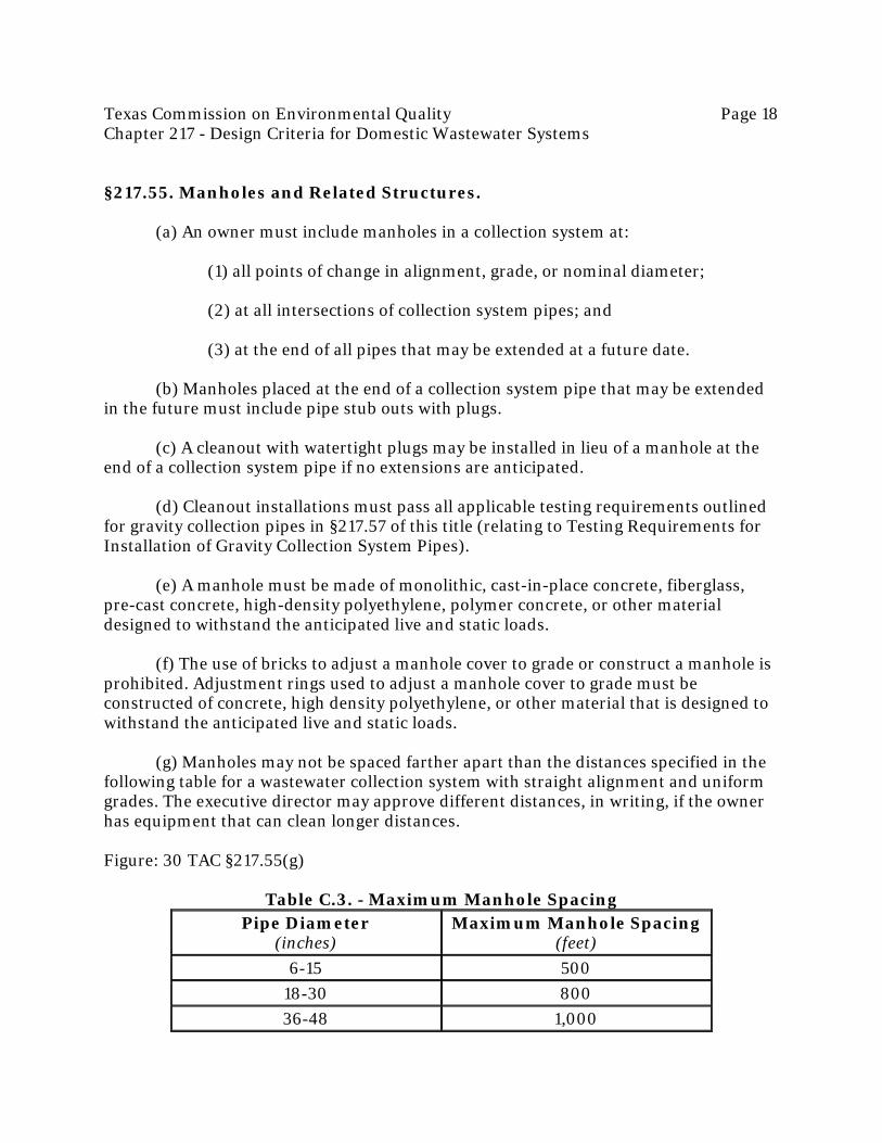
(g) Manholes may not be spaced farther apart than the distances specified in the
following table for a wastewater collection system with straight alignment and uniform grades. The executive director may approve different distances, in writing, if the owner has equipment that can clean longer distances.
Figure: 30 TAC §217.55(g)
Table C.3. - Maximum Manhole Spacing Pipe Diameter
(inches) Maximum Manhole Spacing
(feet) 6-15 500
18-30 800 36-48 1,000

Texas Commission on Environmental Quality Page 19 Chapter 217 - Design Criteria for Domestic Wastewater Systems
54 or larger 2,000 (h) Tunnels are exempt from manhole spacing requirements. (i) A manhole must not be located in a stream bed or other area that prevents
access to the manhole. (j) The inside diameter of a manhole must be no less than 48 inches. A manhole
diameter must be sufficient to allow personnel and equipment to enter, exit, and work in the manhole, and to allow proper joining of the collection system pipes in the manhole wall.
(k) Manholes must meet the following requirements for covers, inlets, and bases.
(1) Manhole Covers.
(A) A manhole where personnel entry is anticipated requires a clear opening with at least a 30 inch diameter.
(B) A manhole located within a 100-year flood plain must be
gasketed and bolted down to prevent inflow. (C) A manhole cover must be constructed of impervious material
with no holes that could allow inflow. (D) A manhole cover that is located in a roadway must meet or
exceed the American Association of State Highways and Transportation Officials standard M-306 for load bearing.
(E) The engineering report must specify and the owner must follow
an appropriate national reference standard for manhole gaskets. (F) Manhole covers must be constructed of cast iron, steel, non-
metallic composite material, fiberglass, or other material approved in writing by the executive director.
(2) Manhole Inverts.
(A) The bottom of a manhole must contain a U-shaped channel that is a smooth continuation of the inlet and outlet pipes.
(B) A manhole connected to pipes less than 15 inches in diameter
must have a channel depth equal to at least half the largest pipe's diameter.

Texas Commission on Environmental Quality Page 20 Chapter 217 - Design Criteria for Domestic Wastewater Systems
(C) A manhole connected to a pipe that is at least 15 inches in
diameter but not more than 24 inches in diameter must have a channel depth equal to at least three-fourths of the largest pipe's diameter.
(D) A manhole connected to a pipe that is greater than 24 inches in
diameter must have a channel depth equal to at least the largest pipe's diameter. (E) In a manhole with pipes of different sizes, the tops of all the
pipes must be at the same elevation and flow channels in the invert must be sloped evenly from pipe to pipe to prevent backpressure.
(F) A bench provided above a channel must slope at a minimum of
0.5 inch per foot. (G) A manhole invert must be filleted to prevent solids from being
deposited if a collection system pipe enters a manhole higher than 24 inches above a manhole invert.
(H) A collection system pipe entering a manhole more than 24
inches above an invert must have a drop pipe.
(l) Steps are prohibited in a manhole. (m) Connections. A manhole-pipe connection must use watertight, size-on-size
resilient connectors that allow for differential settlement and must conform to American Society for Testing and Materials C 923.
(n) Venting.
(1) An owner must ensure that the collection system is vented at least every 1,500 feet.
(2) Vents must be designed to minimize inflow and must be located above
a 100-year flood event elevation. (3) Tunnels must be vented in compliance with this subsection.
(o) Cleanouts. A cleanout diameter must be at least equal to the diameter of the pipe to which it is attached.
Adopted November 4, 2015 Effective December 4, 2015

Texas Commission on Environmental Quality Page 21 Chapter 217 - Design Criteria for Domestic Wastewater Systems §217.56. Trenchless Pipe Installation.
(a) Trenchless technologies that may be used for installation of new collection system pipe include impact moling, pipe ramming, microtunneling, conventional tunneling, bore and jack, and horizontal directional drilling.
(b) Trenchless technologies that may be used for replacement of collection
system pipe include pipe bursting, pipe splitting, and pipe jacking. (c) Trenchless technologies that may be used for lining existing collection system
pipes include epoxy spray lining, cured-in-place pipe, and sliplining. These technologies reduce the inside diameter of a pipe.
(d) All other trenchless methods of installing, replacing, or repairing collection
system pipe are non-conforming technologies subject to the requirements of §217.7(b) of this title (relating to Types of Plans and Specifications Approvals).
(e) A collection system using a trenchless technology must be designed, installed,
operated, maintained, and constructed in accordance with American Society for Testing and Materials (ASTM) or American Water Works Association (AWWA) standards with reference to materials used and construction procedures. In the absence of ASTM or AWWA standards, the executive director review may be based upon other recognized standards used by industry engineers.
(f) The engineering report must include the following:
(1) the trenchless method; (2) the type of pipe; (3) the type(s) of soil; (4) the pipe length and diameter; (5) the pipe slope; (6) the method for disconnecting and reconnecting lateral and service
connections; (7) the provisions for flow bypass for existing system; and (8) the pipe standard.

Texas Commission on Environmental Quality Page 22 Chapter 217 - Design Criteria for Domestic Wastewater Systems
(g) Collection system pipe that is installed using a trenchless technology is subject to the testing requirements in §217.57 of this title (relating to Testing Requirements for Installation of Gravity Collection System Pipes) and §217.68 of this title (relating to Force Main Testing).
Adopted November 4, 2015 Effective December 4, 2015 §217.57. Testing Requirements for Installation of Gravity Collection System Pipes.
(a) For a collection system pipe that will transport wastewater by gravity flow, the design must specify an infiltration and exfiltration test or a low-pressure air test. The test must conform to the following requirements:
(1) Low Pressure Air Test.
(A) A low pressure air test must follow the procedures described in American Society for Testing and Materials (ASTM) C 828, ASTM C 924, or ASTM F 1417 or other procedure approved in writing by the executive director. The testing times listed in Table C.4. in Figure: 30 TAC §217.57(a)(1)(C) or Equation C.3 in Figure: 30 TAC §217.57(a)(1)(B)(ii) must be used, regardless of the testing procedure.
(B) For sections of collection system pipe with an average inside
diameter less than 36 inches, the following procedure applies, unless a pipe is to be tested as required by paragraph (2) of this subsection.
(i) A pipe must be pressurized to 3.5 pounds per square inch
(psi) gauge. If groundwater is present, then a pipe must be pressurized to 3.5 psi gauge greater than the pressure exerted by groundwater above the pipe.
(ii) Once the pressure is stabilized, the minimum time
allowable for the pressure to drop from 3.5 psi gauge to 2.5 psi gauge is computed from the following equation:
Figure: 30 TAC §217.57(a)(1)(B)(ii) Equation C.3.
Where:

Texas Commission on Environmental Quality Page 23 Chapter 217 - Design Criteria for Domestic Wastewater Systems T = time for pressure to drop 1.0 pound per square inch gauge in seconds K = 0.000419×D×L, but not less than 1.0 D = average inside pipe diameter in inches L = length of pipe line, in feet Q = rate of loss, 0.0015 cubic feet per minute per square foot internal surface
(C) Since a K value of less than 1.0 may not be used, the minimum
testing time for each pipe diameter is shown in the following table: Figure: 30 TAC §217.57(a)(1)(C)
Table C.4. - Minimum Testing Times for Low-Pressure Air Test Pipe
Diameter (inches)
Minimum Time
(seconds)
Maximum Length for Minimum Time
(feet)
Time for Longer Length
(seconds/foot) 6 340 398 0.855 8 454 298 1.520 10 567 239 2.374 12 680 199 3.419 15 850 159 5.342 18 1,020 133 7.693 21 1,190 114 10.471 24 1,360 100 13.676 27 1,530 88 17.309 30 1,700 80 21.369 33 1,870 72 25.856
(D) An owner may stop a test if no pressure loss has occurred
during the first 25% of the calculated testing time. (E) If any pressure loss or leakage has occurred during the first 25%
of a testing period, then the test must continue for the entire test duration as outlined above or until failure of the test.
(F) Collection system pipes with a 27 inch or larger average inside
diameter may be air tested at each joint instead of following the procedure outlined in this section.
(G) A testing procedure for a pipe with an inside diameter greater
than 33 inches must be approved in writing by the executive director.

Texas Commission on Environmental Quality Page 24 Chapter 217 - Design Criteria for Domestic Wastewater Systems
(2) Infiltration/Exfiltration Test.
(A) The total exfiltration, as determined by a hydrostatic head test, must not exceed 10 gallons per inch of diameter per mile of pipe per 24 hours at a minimum test head of 2.0 feet above the crown of a pipe at an upstream manhole, or at least two feet above the existing groundwater level, whichever is greater.
(B) An owner shall use an infiltration test in lieu of an exfiltration
test when pipes are installed below the groundwater level. (C) If the quantity of infiltration or exfiltration exceeds the
maximum quantity specified, an owner shall take remedial action in order to reduce the infiltration or exfiltration to an amount within the limits specified by Equation C.3. in Figure: 30 TAC §217.57(a)(1)(B)(ii) before putting the system into service. An owner shall retest a pipe following a remedial action according to the requirements of this chapter.
(b) If a gravity collection system pipe is composed of flexible pipe, deflection
testing is also required.
(1) For a collection system pipe with an inside diameter less than 27 inches, deflection measurement requires a rigid mandrel.
(A) Mandrel Sizing.
(i) A rigid mandrel must have an outside diameter not less than 95% of the base inside diameter or average inside diameter of a pipe, as specified in the appropriate standard by the ASTM, American Water Works Association, UNI-BELL, or American National Standards Institute.
(ii) If the mandrel diameter is not specified in the standard
used in clause (i) of this subparagraph, the mandrel must have an outside diameter equal to 95% of the inside diameter of a pipe. In this case, the inside diameter of the pipe, for the purpose of determining the outside diameter of the mandrel, must equal the average outside diameter minus two minimum wall thicknesses for outside diameter controlled pipe and the average inside diameter for inside diameter controlled pipe.
(iii) All mandrel dimensions must meet the standard used in
clause (i) of this subparagraph.
(B) Mandrel Design.

Texas Commission on Environmental Quality Page 25 Chapter 217 - Design Criteria for Domestic Wastewater Systems
(i) A mandrel must be constructed of a metal or a rigid plastic material that can withstand 200 psi without being deformed. Adjustable or flexible mandrels are prohibited.
(ii) A mandrel must have an odd number of runners or legs. (iii) A mandrel must have nine or more runners or legs. (iv) The length of the mandrel's barrel section must equal at
least 75% of the inside diameter of the collection system pipe. (v) Each mandrel size must use a separate proving ring.
(C) Method Options. (i) An owner may not use television inspection as a substitute
for a deflection test. (ii) If requested, the executive director may approve, in
writing, the use of a deflectometer or a mandrel with removable legs or runners on a case-by-case basis.
(D) Trenchless Testing. The executive director may exempt pipe
sections installed by trenchless technologies from mandrel testing in writing on a case-by-case basis.
(2) For a gravity collection system pipe with an inside diameter of 27
inches and greater, other test methods approved in writing by the executive director may be used to determine vertical deflection.
(3) A deflection test method must be accurate to within plus or minus
0.2% deflection. (4) An owner shall not conduct a deflection test until at least 30 days after
the final backfill. (5) Collection system pipe deflection must not exceed 5%. (6) If a pipe section fails a deflection test, an owner shall correct the
problem immediately, and then must conduct a second test after the final backfill has been in place at least 30 days.

Texas Commission on Environmental Quality Page 26 Chapter 217 - Design Criteria for Domestic Wastewater Systems
(7) An owner shall not use any mechanical pulling devices during deflection testing.
(8) An owner shall include a certification in the notice of completion
required in §217.14 of this title (relating to Completion Notice), that the collection system passed the deflection tests.
(c) An owner of a collection system must inspect the structural integrity of the
collection system under the direction of an engineer during the construction and testing phases of the project. Adopted November 4, 2015 Effective December 4, 2015 §217.58. Testing Requirements for Manholes.
(a) All manholes must pass a leakage test. (b) An owner shall test each manhole, after assembly and before backfilling, for
leakage using hydrostatic exfiltration testing, vacuum testing, or any other method approved in writing by the executive director. A manhole must be tested separately and independently from the collection system pipes.
(1) Hydrostatic Testing.
(A) The maximum leakage rate for hydrostatic testing or any alternative test methods is 0.025 gallons per foot diameter per foot of manhole depth per hour.
(B) To perform a hydrostatic test, an owner shall seal all wastewater
pipes coming into the manhole with an internal pipe plug, fill the manhole with water, and maintain the test for at least one hour.
(C) A test for concrete manholes may use a 24-hour wetting period
before testing to allow saturation of the concrete.
(2) Vacuum Testing. An owner must perform vacuum testing according to either subparagraph (A) or (B) of this paragraph. If a manhole fails the vacuum test, the owner must apply grout to the exterior of the excavated manhole before retesting the manhole.
(A) Texas Test.

Texas Commission on Environmental Quality Page 27 Chapter 217 - Design Criteria for Domestic Wastewater Systems
(i) To perform a vacuum test, an owner shall plug all lift holes and exterior joints with a non-shrink grout and plug all pipes entering a manhole.
(ii) Grout may not be placed in horizontal joints before
testing.
(iii) Stub-outs, manhole boots, and pipe plugs must be secured to prevent movement while a vacuum is drawn.
(iv) An owner shall use a minimum 60 inch/lb torque
wrench to tighten the external clamps that secure a test cover to the top of a manhole. (v) A test head must be placed at the inside of the top of a
cone section, and the seal must be inflated in accordance with the manufacturer's recommendations.
(vi) There must be a vacuum of 10 inches of mercury inside a
manhole to perform a valid test. (vii) A test does not begin until after the vacuum pump is off. (viii) A manhole passes the test if after 2.0 minutes and with
all valves closed, the vacuum is at least 9.0 inches of mercury.
(B) American Society for Testing and Materials (ASTM) Test. The owner may require manhole testing that meets the requirements of ASTM D1244-11. Adopted November 4, 2015 Effective December 4, 2015 §217.59. Lift Station Site Requirements.
(a) Site access.
(1) A lift station must be located in a right-of-way or a permanent easement.
(2) A lift station site must be accessible by truck during all weather
conditions, including a 25-year, 24-hour rainfall event. (3) A road surface used to access a lift station must have a minimum width
of 12 feet.
(b) Security.

Texas Commission on Environmental Quality Page 28 Chapter 217 - Design Criteria for Domestic Wastewater Systems
(1) The design of a lift station, including all mechanical and electrical
equipment, must restrict access by an unauthorized person. (2) A lift station must include an intruder-resistant fence, or must be
completely enclosed by an intruder-resistant enclosure approved in writing by the executive director.
(A) An intruder-resistant fence or intruder-resistant enclosure must
be locked at each access point. (B) An intruder-resistant fence must be at least 6.0 feet tall, and the
bottom of the fence must be close enough to surface grade to prevent human access. (C) An intruder-resistant fence must be constructed of wood,
concrete, masonry, or metal. Other materials may be used, but only if approved in writing by the executive director.
(D) The top of an intruder-resistant fence must have at least three
strands of barbed wire. A fence that is at least 8.0 feet tall does not require barbed wire. The top of an intruder-resistant fence may have outwardly-directed iron bars spaced on four-inch centers instead of barbed wire.
(3) Above-ground valves located outside of an intruder-resistant fence
must be chained and locked to prevent unauthorized operation. A valve does not need to be chained if the valve is located below ground or if the valve is fully enclosed in an intruder-resistant enclosure designed to prevent unauthorized operation.
(c) Flood Protection. The design of a lift station, including all electrical and
mechanical equipment, must be designed to withstand and operate during a 100-year flood event, including wave action.
(d) Odor Control. An owner shall implement odor control measures necessary to
prevent a lift station from becoming a nuisance.
Adopted November 4, 2015 Effective December 4, 2015 §217.60. Lift Station, Wet Well, and Dry Well Designs.
(a) Pump Controls.
(1) A lift station pump must operate automatically, based on the water level in a wet well. Pump controls must be designed to prevent surcharges in the

Texas Commission on Environmental Quality Page 29 Chapter 217 - Design Criteria for Domestic Wastewater Systems collection system and must be designed to prevent adverse effects on the operation of the wastewater treatment facility.
(2) The location of a wet well water level mechanism must ensure that the
mechanism is unaffected by currents, rags, grease, or other floating materials. (3) A wet well water level mechanism must be accessible without entering
the wet well. (4) Wet wells with a bubbler system require dual air supplies and dual
controls. (5) Motor control centers must be mounted high enough above grade, but
in no case less than 4.0 inches above grade, to prevent water intrusion and corrosion from standing water in the enclosure. Motor control centers must also be protected from the entrance of corrosive gases from wet wells or piping.
(6) Electrical equipment and electrical connections in a wet well or a dry
well must meet National Fire Protection Association 70 National Electrical Code® explosion prevention requirements, unless continuous ventilation is provided.
(7) Electronic wet well level control systems must also use a float switch or
similar manual backup. (8) Wet well control settings must be designed to discourage septic
conditions in a lift station. (9) Wet well control settings must be designed to prevent overloading of
downstream pipes and treatment units.
(b) Wet Wells.
(1) A wet well must be enclosed by watertight and gas tight walls. (2) A penetration through a wall of a wet well must be gas tight. (3) A wet well must not contain equipment requiring regular or routine
inspection or maintenance, unless inspection and maintenance can be done without a person entering the wet well.
(4) A gravity pipe discharging to a wet well must be located so that the
invert elevation is above the liquid level of a pump's "on" setting.

Texas Commission on Environmental Quality Page 30 Chapter 217 - Design Criteria for Domestic Wastewater Systems
(5) Gate valves and check valves are prohibited in a wet well. (6) Gate valves and check valves may be located in a valve vault next to a
wet well or in a dry well. Valve vaults shall be ventilated according to subsection (d) of this section.
(7) A pump must run continuously during the pump cycle time, which
begins when the pump is activated by the pump controls. Pump cycle time, based on peak flow, must equal or exceed those in the following table:
Figure: 30 TAC §217.60(b)(7)
Table C.5. - Minimum Pump Cycle Times Pump Horsepower Minimum Cycle Times
(minutes) < 50 6
50-100 10 > 100 15
(8) An evaluation of minimum wet well volume requires the following
formula:
Figure: 30 TAC §217.60(b)(8) Equation C.4.
Where: V = Active volume (cubic feet) Q = Pump capacity (gallons per minute) T = Cycle time (minutes) 7.48 = Conversion factor (gallons/cubic foot)
(c) Dry well access.
(1) An underground dry well must be accessible for maintenance and shall be ventilated according to subsection (d) of this section.

Texas Commission on Environmental Quality Page 31 Chapter 217 - Design Criteria for Domestic Wastewater Systems
(2) A stairway in a dry well must use non-slip steps and conform to Occupational Safety and Health Administration regulations with respect to rise and run.
(3) A ladder in a dry well must be made of non-conductive material and be
rated for the load necessary for staff and equipment to descend and ascend.
(d) Lift Station Ventilation.
(1) Passive Ventilation for Wet Wells.
(A) Passive ventilation structures must include screening to prevent the entry of birds and insects to a wet well. The screening must be made of corrosion-resistant material.
(B) All mechanical and electrical equipment in a wet well with
passive ventilation must be constructed in compliance with explosion requirements in the National Fire Protection Association 70 National Electrical Code®.
(C) A passive ventilation system must be sized to vent at a rate
equal to the maximum pumping rate of a lift station, but not to exceed 600 feet per minute through a vent pipe.
(D) The minimum acceptable diameter for an air vent is 4.0 inches. (E) All vent outlets must be at least 1.0 foot above a 100-year flood
plain elevation.
(2) Mechanical Ventilation in Lift Stations.
(A) Dry Wells.
(i) A dry well must use mechanical ventilation. (ii) Ventilation equipment under continuous operation must
have a minimum capacity of six complete air exchanges per hour. (iii) Ventilation equipment under intermittent operations
must provide a minimum capacity of 30 complete air exchanges per hour and be connected to the lift station's lighting system.
(B) Wet Wells.

Texas Commission on Environmental Quality Page 32 Chapter 217 - Design Criteria for Domestic Wastewater Systems
(i) Mechanical ventilation systems for wet wells must operate continuously.
(ii) The ventilation equipment must provide at least 12
complete air exchanges per hour and be constructed of corrosion-resistant material. (iii) An owner shall implement odor control measures
necessary to prevent a wet well from becoming a nuisance. An owner shall consider the source of potential odor, turbulence, residence time, and other factors that contribute odor at a lift station when selecting odor control measures.
(iv) All mechanical and electrical equipment in a wet well
with mechanical ventilation must be constructed in compliance with explosion requirements in National Fire Protection Association 70 National Electrical Code®.
(e) Wet Well Slopes.
(1) A wet well floor must have a smooth finish and minimum slope of 10% to a pump intake.
(2) A wet well design must prevent deposition of solids, grease, and debris
under normal operating conditions. (3) A lift station with greater than 5.0 million gallons per day firm
pumping capacity must have anti-vortex baffling.
(f) Hoisting Equipment. A lift station must have permanent hoisting equipment or be accessible to portable hoisting equipment for removal of pumps, motors, valves, pipes, and other similar equipment.
(g) Valve Vault Drains. A floor drain from a valve vault to a wet well must prevent
gas from entering a valve vault by including flap valves, "P" traps, submerged outlets, or a combination of these devices.
(h) Dry Well Sump Pumps.
(1) Pumps.
(A) A dry well must use dual sump pumps, each with a minimum capacity of 1,000 gallons per hour and capable of handling the volume of liquid necessary to prevent accumulation of water from condensation and incidental leaks during peak pumping operations.

Texas Commission on Environmental Quality Page 33 Chapter 217 - Design Criteria for Domestic Wastewater Systems
(B) A sump pump must have a submersible motor and watertight wiring.
(C) A dry well floor must slope toward the sump. A sump must
include sump pumps sized to prevent accumulation of water from condensation and incidental leaks.
(D) The minimum sump depth is 6.0 inches. The sump must
prevent standing water from accumulating on a dry well floor under normal operation. (E) A sump pump must operate automatically by use of a float
switch or another level-detecting device.
(2) Pipes.
(A) A sump pump must use independent piping that is capable of discharging more than the maximum liquid level of an associated wet well at a rate that will prevent overflow of the wet well.
(B) A sump pump outlet pipe must be at least 1.5 inches in diameter
and have at least two check valves in series.
Adopted November 4, 2015 Effective December 4, 2015 §217.61. Lift Station Pumps.
(a) General Requirements. A raw wastewater pump, with the exception of a grinder pump, must:
(1) be designed to prevent clogging; (2) be capable of passing a sphere of 2.5 inches in diameter or greater; and (3) have greater than 3.0 inch diameter suction and discharge openings.
(b) Submersible and Non-submersible Pumps.
(1) A non-submersible pump must have inspection and cleanout plates on both the suction and discharge sides of each pumping unit that facilitate locating and removing blockage-causing materials, unless the pump design accommodates easy removal of the rotation elements.

Texas Commission on Environmental Quality Page 34 Chapter 217 - Design Criteria for Domestic Wastewater Systems
(2) A pump support for a submersible or non-submersible pump must prevent movement and vibration during operation.
(3) A submersible pump must use a rail-type pump support system with
manufacturer-approved mechanisms designed to allow personnel to readily remove and replace any single pump without entering or dewatering the wet well.
(4) Submersible pump rails and lifting chains must be constructed of a
material that performs to at least the standard of Series 300 stainless steel. (5) All lift station pumps and associated appurtenances must be designed
to prevent the discharge of wastewater from the lift station and at all points in the upstream collection system.
(c) Lift Station Pumping Capacity. A lift station must have at least two pumps.
The firm pumping capacity of a lift station must handle the peak flow. (d) Pump Head Calculations.
(1) An owner must select a pump based upon analysis of the system head and pump capacity curves. The owner must determine the pumping capacities and pressure head requirements of a single pump operating alone, and with other pumps.
(2) The engineering report must include pipe head loss calculations, using
the American National Standards Institute's Hydraulic Institute Standards pertaining to head losses through pipes, valves, and fittings.
(3) The engineering report must include the friction coefficient (Hazen-
Williams "C" value) used in friction head loss calculations. The selected friction coefficient must be based on the pipe material.
(4) For a lift station with more than two pumps, a force main in excess of
one-half mile, or a lift station with a firm pumping capacity of 100 gallons per minute or greater, the engineering report must include system curves for both the normal and peak operating conditions at friction coefficient values (C values) for the force main pipe.
(e) Flow Control.
(1) A lift station or a transfer pumping station located at or discharging directly to a wastewater treatment facility must have a peak pump capacity equal to or less than the peak flow, unless equalization is provided.

Texas Commission on Environmental Quality Page 35 Chapter 217 - Design Criteria for Domestic Wastewater Systems
(2) Each lift station or transfer pumping station located at or discharging directly to a wastewater treatment facility with a peak flow that is greater than 300,000 gallons per day must use three or more pumps, unless duplex, automatically controlled, variable capacity pumps are used.
(3) Each lift station or transfer pumping station located at or discharging
directly to a wastewater treatment facility with a peak flow that is less than or equal to 300,000 gallons per day must use at least two pumps.
(f) Self-Priming Pumps.
(1) A self-priming pump must be capable of priming without relying on a separate priming system, an internal flap valve, or any other external method for priming.
(2) A self-priming pump must use a suction pipe that produces flow with
velocity of at least 3.0 feet per second but not more than 7.0 feet per second. A self-priming pump must have its own suction pipe.
(3) A self-priming pump must vent air back into the wet well during
priming.
(g) Vacuum-Priming Pumps.
(1) A vacuum-primed pump must be capable of priming by using a separate positive priming system with a dedicated vacuum pump for each main wastewater pump.
(2) A vacuum-priming pump must produce a suction pipe velocity between
3.0 and 7.0 feet per second. A vacuum priming pump must have its own suction pipe.
(h) Vertical Positioning of Pumps. A raw wastewater pump must maintain positive static suction head during normal on-off cycling. A submersible pump with "no suction" pipes, a vacuum-primed pump, or a self-priming unit capable of satisfactory operation under any negative suction head anticipated for the lift station is not required to have positive static suction head during normal on-off cycling.
(i) Individual Grinder Pumps. A grinder pump is not subject to the requirements
of this subchapter if:
(1) the grinder pump is not part of an alternative collection system as defined by this chapter; and
Texas Commission on Environmental Quality Page 36 Chapter 217 - Design Criteria for Domestic Wastewater Systems
(2) the grinder pump only serves a single connection to a wastewater collection system.
(j) Pump for Low-Flow Lift Station. A pump used for a lift station with a peak
flow of less than 120 gallons per minute must be submersible and include a grinder.
Adopted November 4, 2015 Effective December 4, 2015 §217.62. Lift Station Pipes.
(a) Horizontal Pump Suctions.
(1) Each lift station pump must have a separate suction pipe that uses an eccentric reducer.
(2) Pipes in a wet well must have a turndown-type flared intake.
(b) Valves.
(1) The discharge side of each lift station pump must be followed by a full-closing isolation valve and must also have a check valve.
(A) A check valve must be a swing type valve with an external lever
or external position indicator to show its open and closed positions. (B) An isolation valve must include an external position indicator to
show its open and closed positions, unless a full-closing valve is a rising-stem gate valve.
(2) A grinder pump installation may use a rubber-ball check valve or a swing-type check valve.
(3) A butterfly valve, tilting-disc check valve, or any other valve using a
tilting-disc in a pipe is prohibited.
(c) Pipes.
(1) A lift station pipe must have flanged or flexible connections to allow for removal of pumps and valves without interruption of the lift station operations.
(2) Wall penetrations must allow for pipe flexure while excluding
exfiltration or infiltration.

Texas Commission on Environmental Quality Page 37 Chapter 217 - Design Criteria for Domestic Wastewater Systems
(3) Pipe suction velocities must be at least 3.0 feet per second but not more than 7.0 feet per second.
Adopted November 4, 2015 Effective December 4, 2015 §217.63. Emergency Provisions for Lift Stations.
(a) A lift station must include a sign with the name of the wastewater treatment facility and 24-hour emergency contact information. The sign must be posted at the lift station so that it is visible and legible, with block lettering that is at least 1.5 inches tall.
(b) A lift station must be designed to prevent the discharge of wastewater from
the lift station and at all points in the upstream collection system during electrical power failures.
(c) A lift station must include an audiovisual alarm system. The audiovisual
alarm system must transmit alarm conditions through use of an auto-dialer system, Supervisory Control and Data Acquisition (SCADA) system, or telemetering system connected to a continuously monitored location. At a minimum, the alarm system must automatically activate to give warnings for power outages, pump failures, and high water levels. Audiovisual alarms are not required if the SCADA system alerts the operator about communication loss, in addition to the alarm conditions.
(d) An alarm system must include self-testing capability at the control panel.
(e) An owner shall determine the reliability of the existing commercial power service for a lift station using records from the past 60 consecutive months from the electric utility that serves the lift station. The entire record must be used if 60 months of records are not available. The owner must provide the power outage records and the reliability determination in the engineering report. The records must:
(1) be in writing; (2) be on the utility's letterhead and bear a signature of an electric utility
employee who has knowledge of data about power outages; (3) identify the location of the lift station;
(4) list the total number of outages that have occurred during the past 60
consecutive months; and (5) indicate the date and duration of each recorded power outage.
Texas Commission on Environmental Quality Page 38 Chapter 217 - Design Criteria for Domestic Wastewater Systems
(f) The executive director may consider documentation of commercial power system upgrades and their effects on the reliability of commercial power. Documentation of upgrades and their effects on power reliability must be submitted in writing on the electric utility's letterhead and must bear the signature of an electric utility employee who has knowledge of the system upgrades.
(g) Systems for preventing the discharge of wastewater must operate for a
duration at least equal to the longest power outage on record for the past 60 months, or at least 20 minutes, whichever is longer. The design must be based on peak flows, inflow, and infiltration. If the longest power outage on record for the past 60 consecutive months is greater than 48 hours and generators will be used to provide backup power, then the owner must have a contract in place that guarantees fuel supply during an emergency. The owner must also have sufficient storage capacity at the wastewater treatment facility for the fuel for the duration of the emergency.
(h) For calculation purposes, the owner must assume that the lift station wet well
is full to the pump activation level when the power outage period begins. (i) Systems for preventing discharge of wastewater may include any combination
of alternate power sources, on-site generators, portable generators, gravity relief sewers, bypass pumps, collection system storage, spill containment structures, and other systems approved in writing by the executive director. For purposes of this section, a gravity relief sewer is the part of a collection system built to manage the flow of wastewater that exceeds the capacity of the existing collection system by passively transporting the flow to a different part of the collection system or to another wastewater treatment facility.
(1) The system or combination of systems must accommodate the firm
pumping capacity of the lift station.
(2) Collection system storage must not be used as a sole system for preventing unauthorized discharge of wastewater.
(3) A spill containment structure must not be used as a sole system for preventing unauthorized discharge of wastewater.
(4) Portable generators and pumps may only be used to guarantee service
if:
(A) a tested quick-connect mechanism or a transfer switch properly sized to connect to a portable generator is provided where the generator will be used; and

Texas Commission on Environmental Quality Page 39 Chapter 217 - Design Criteria for Domestic Wastewater Systems
(B) a licensed operator that is knowledgeable in operation of the portable generators and pumps will be on call 24 hours per day every day.
(5) If portable generators and pumps are used to guarantee service, the
engineering report must include:
(A) the storage location of each generator and pump; (B) the amount of time that will be needed to transport each
generator or pump from the storage location to the furthest lift station that will be served by the generator or pump;
(C) how many lift stations each backup generator or pump serves;
and (D) the type of routine maintenance and upkeep that will be done
for each portable generator and pump to ensure that they will be operational when needed.
(j) Systems for preventing discharge of wastewater at a lift station must be
permanent features of the lift station or must be deployable during any electrical power outage. Deployable systems must be operational before any unauthorized discharge occurs. The owner must describe how a temporary power system will be deployed and operated in the engineering report, and must address deployment during all types of weather events that might reasonably cause power outage at the lift station.
(k) Spill containment structures must be able to be cleaned and must have an
intruder-resistant fence that meets the requirements in §217.59(b) of this title (relating to Lift Station Site Requirements). The engineering report must include a detailed management plan for cleaning and maintaining each spill containment structure.
(l) A lift station must be fully accessible during a 25-year, 24-hour rainfall event.
(m) Lift station pump controls must prevent over-pumping and surcharge upon
resumption of normal power after a power outage.
Adopted November 4, 2015 Effective December 4, 2015 §217.64. Materials for Force Main Pipes.
(a) Force main pipe material must withstand the pressure generated by instantaneous pump stoppage due to power failure under maximum pumping conditions.

Texas Commission on Environmental Quality Page 40 Chapter 217 - Design Criteria for Domestic Wastewater Systems
(b) The use of pipes or fittings rated at a working pressure of less than 150 pounds per square inch is prohibited.
(c) Force main pipe materials must be identified in the specifications with the
appropriate specification number for both quality control and installation from the American Society for Testing and Materials, American National Standards Institute, or American Water Works Association.
(d) Pipe material specified for a force main must have an expected life equal to or
longer than that of the lift station and must be non-corrosive.
Adopted November 4, 2015 Effective December 4, 2015 §217.65. Force Main Pipe Joints.
(a) An underground force main pipe joint must include either push-on rubber gaskets or mechanical joints with a pressure rating equal to or greater than that of the force main pipe material.
(b) Exposed force main pipe joints must be flanged or flexible and adequately
secured to prevent movement due to wastewater surges. (c) American Society for Testing and Materials, American Water Works
Association, or other widely accepted national reference standards for the joints must be included in the project specifications.
Adopted November 4, 2015 Effective December 4, 2015 §217.66. Identification of Force Main Pipes.
(a) A detectable underground warning tape must be laid in the same trench as a force main pipe. The detectable underground warning tape must be located above and parallel to the force main.
(b) The detectable underground warning tape must bear the label
"PRESSURIZED WASTEWATER" continuously repeated in at least 1.5 inch tall letters.
Adopted November 4, 2015 Effective December 4, 2015 §217.67. Force Main Design.
(a) Velocities.

Texas Commission on Environmental Quality Page 41 Chapter 217 - Design Criteria for Domestic Wastewater Systems
(1) A force main must be a minimum of 4.0 inches in diameter, unless it is used in conjunction with a grinder pump station. The executive director may approve pipes with a diameter less than 4.0 inches where grinder pumps are used, on a case-by-case basis in writing.
(2) For a lift station with two pumps, the minimum velocity is 3.0 feet per
second with one pump in operation. (3) For a lift station with three or more pumps:
(A) the minimum velocity in a force main is 2.0 feet per second with only the smallest pump operating at full speed; and
(B) a minimum flushing velocity of 5.0 feet per second or greater
must occur in a force main at least twice daily.
(4) The engineering report must certify that a pipeline with a velocity greater than 6.0 feet per second can withstand high and low negative surge pressures in the event of sudden pump failure.
(b) Detention Time.
(1) Force main detention time calculations must be included in the engineering report.
(2) Force main detention time calculations must be performed using a
range of flow rates that represent the flows expected to be delivered to a force main by an upstream pump station during any 24-hour period.
(c) Water Hammer. A force main design must include effective surge control
measures to manage pressure due to water hammer that may exceed the working strength of a force main pipe.
(d) Connection to Gravity Main.
(1) A force main must terminate at a collection system manhole or at a manhole or preliminary treatment unit at a wastewater treatment facility.
(2) The discharge end of a force main inside a manhole must be restrained
to prevent movement and must produce non-turbulent flow.

Texas Commission on Environmental Quality Page 42 Chapter 217 - Design Criteria for Domestic Wastewater Systems
(3) A collection system receiving wastewater from a force main must be designed to accept the maximum pump discharge from the force main without surcharging.
(e) Pipe Separation. A separation distance between a force main and any water
supply pipe must meet the minimum separation requirements established in §217.53(d) of this title (relating to Pipe Design).
(f) Odor Control.
(1) A force main must terminate such that the flowline of the force main entering the manhole matches the flowline of the gravity pipe leaving the manhole.
(2) A force main must be designed to abate anticipated odor. An owner
shall implement odor control measures necessary to prevent a collection system from becoming a nuisance.
(g) Air Release Valves in Force Mains.
(1) Any high point along the vertical force main alignment must include an air release valve or a combination of air release and air vacuum valves.
(2) An air release valve must have an isolation valve between the air
release valve and the force main. (3) An air release valve must be inside of a vault that is at least 48 inches
in diameter and has a vented access opening of at least 30 inches in diameter. (4) An air release valve must be made of corrosion-resistant material.
(h) Valves. A force main must have valves spaced at no more than 2,000 foot intervals to facilitate initial testing and subsequent maintenance and repairs.
(i) Fatigue Life. The engineering report must include calculations that show the
strength of the force main pipe at the end of the 50-year design life. The calculations must consider the fluctuations between a pressurized and depressurized operating state.
(j) Alignment Changes.
(1) Bending a segmented pipe is prohibited, unless the pipe joints are welded or heat-fused.

Texas Commission on Environmental Quality Page 43 Chapter 217 - Design Criteria for Domestic Wastewater Systems
(2) Force main alignment changes must be accomplished using manufactured bend fittings.
(3) Force main pipe joints must include mechanical joint restraints or
thrust blocks at all bends unless pipe vibration calculations justify the absence of a joint restraint or thrust block.
Adopted November 4, 2015 Effective December 4, 2015 §217.68. Force Main Testing.
(a) The final plans and specifications must include the pressure testing procedures.
(b) A pressure test must use 50 pounds per square inch above the normal
operating pressure of a force main. (c) A temporary valve for pressure testing may be installed near the discharge
point of a force main and must be removed after a test is successfully completed. (d) A pump isolation valve may be used as an opposite termination point. (e) A test must involve filling a force main with water. (f) A pipe must hold the designated test pressure for a minimum of 4.0 hours. (g) The leakage rate must not exceed 10.0 gallons per inch of diameter per mile of
pipe per day. The following equation must be used to calculate the acceptable leakage rate in gallons per hour per 1,000 feet of pipe. Figure: 30 TAC §217.68(g) Equation C.5.
𝐿𝐿 = 𝑆𝑆𝑆𝑆√𝑃𝑃
155,400
Where: L = Acceptable leakage rate (gallons/hour/1,000 feet of pipe, based on a leakage rate of
10.0 gallons per inch of diameter per mile of pipe per day) S = Length of pipe (feet) D = Nominal diameter of pipe (inches) P = Average test pressure (ponds/square inch)

Texas Commission on Environmental Quality Page 44 Chapter 217 - Design Criteria for Domestic Wastewater Systems
Adopted November 4, 2015 Effective December 4, 2015 §217.69. Maintenance, Inspection, and Rehabilitation of the Collection System.
(a) The owner of a collection system shall develop a maintenance and inspection program for its collection system with the assistance of an engineer and licensed operators. The owner is responsible for ensuring that the maintenance and inspection program includes all the information pertaining to inspection, maintenance, and rehabilitation of the collection system necessary to ensure efficient, safe, and environmentally compliant operation. The owner is also responsible for ensuring that all records pertaining to maintenance, inspection, and rehabilitation activities are maintained by the licensed collection system operators. The inspection program must include, at a minimum:
(1) a schedule for inspections, cleaning, and maintenance; (2) methods for inspecting, cleaning, and maintaining each unit within the
collection system; (3) methods for estimating the current condition and life expectancy of
each unit; and (4) a requirement to estimate the structural integrity of each collection
system unit.
(b) The plans and specifications for a rehabilitation project must include, at a minimum:
(1) a surface preparation plan that includes:
(A) a cleaning plan to remove all contaminants; (B) references for the cleaning method; (C) dewatering or bypassing provisions; and (D) field preparation and application logs;
(2) a plan for managing volatile chemicals and dust in confined spaces;

Texas Commission on Environmental Quality Page 45 Chapter 217 - Design Criteria for Domestic Wastewater Systems
(3) a requirement to follow the manufacturer's installation procedures and specifications;
(4) a requirement to re-inspect the rehabilitation project, including the
underlayment and coating, between six months and 11 months after installation; and (5) a requirement to re-inspect the rehabilitation project, including the
underlayment and coating, 18 months after installation.
(c) The owner must maintain records of all activities related to collection system inspection, maintenance, cleaning, and rehabilitation. The records must be made available to the executive director upon request according to the requirements of §217.18 of this title (relating to Provisions that Apply to All Sections in this Chapter).
Adopted November 4, 2015 Effective December 4, 2015 §217.70. Reclaimed Water Facilities.
(a) In accordance with §217.6 of this title (relating to Submittal Requirements and Review Process), the design of a distribution system that will convey reclaimed water to a user must be submitted, reviewed, and approved in writing by the executive director before the distribution system may be used.
(b) A municipality may be the review authority in accordance with §217.8 of this
title (relating to Municipality Reviews), and may approve a reclaimed water distribution system.
(c) A distribution system designed to transport Type II reclaimed water, as
defined by §210.33(2) of this title (relating to Quality Standards for Using Reclaimed Water), must comply with this subchapter, as applicable to the project.
(d) A distribution system designed to transport Type I reclaimed water, as
defined by §210.33(1) of this title must meet the requirements of subsections (e) - (j) of this section.
(e) Type I reclaimed water gravity pipes must comply with §§217.53 - 217.55,
217.58, and 217.59 of this title (relating to Pipe Design; Criteria for Laying Pipe; Manholes and Related Structures; Testing Requirements for Manholes; and Lift Station Site Requirements). Type I reclaimed water pipe design must prevent pipe and bedding displacement.
(f) Each appurtenance designed to handle reclaimed water must be identified in
the plans and the engineering report.

Texas Commission on Environmental Quality Page 46 Chapter 217 - Design Criteria for Domestic Wastewater Systems
(1) An above-ground hose bib, spigot, or other hand-operated connection
is prohibited, except in a lockable, secured area that is only accessible to authorized personnel.
(2) An underground hose bib must:
(A) be located in a locked, below-grade vault, or be operated only by a special tool in a non-lockable, underground service box;
(B) be clearly labeled "NON-POTABLE WATER, DO NOT DRINK"
and "NO BEBA EL AGUA;" (C) be purple; and (D) be designed to prevent a connection to a standard water hose.
(3) Reclaimed water storage areas, hose bibs, and spigots must include signs in both English and Spanish reading "NON-POTABLE WATER, DO NOT DRINK" and "NO BEBA EL AGUA."
(g) Cross Connection Control and Separation Distances.
(1) A Type I reclaimed water pipe must be at least 4.0 feet from a potable water pipe, as measured from the outside surface of each of the respective pipes.
(2) A physical connection between a potable water pipe and a reclaimed
water pipe is prohibited. (3) Backflow prevention must be provided for all potable water
connections to prevent any possibility of reclaimed water entering a drinking water system according to the requirements of §217.330 of this title (relating to Drinking Water Supply Connections).
(4) Where a 4.0 foot separation distance cannot be achieved, a reclaimed
water pipe must meet the requirements of subparagraph (A) of this paragraph if the reclaimed water pipe runs parallel to the potable water pipe or subparagraph (B) of this paragraph if the reclaimed water pipe crosses the potable water pipe.
(A) If a new Type I reclaimed water pipe is installed parallel to an
existing potable water pipe, the reclaimed water pipe must:
Texas Commission on Environmental Quality Page 47 Chapter 217 - Design Criteria for Domestic Wastewater Systems
(i) be located below the potable water pipe and maintain a horizontal separation distance of no less than 3.0 feet;
(ii) have a minimum pipe stiffness of 115 pounds per square
inch (psi) with compatible joints, or a pressure rating of 150 psi for both pipe and joints; and
(iii) be embedded in cement stabilized sand that meets the
requirements of subparagraph (D) of this paragraph.
(B) If a new Type I reclaimed water pipe crosses a potable water pipe, the design of the reclaimed water pipe must:
(i) include one full segment of reclaimed water pipe that is
centered on the potable water pipe such that the joints of the reclaimed water pipe are equidistant from the center point of the potable water pipe;
(ii) cross the potable water pipe at a point that is equidistant
between the joints of the potable water pipe; and (iii) have a separation of at least six inches between the
outsides of the pipes.
(C) A Type I reclaimed water pipe must have either a pressure rating of 150 psi for both pipe and joints or a pipe stiffness of at least 115 psi with compatible joints for a minimum distance of 4.0 feet in each direction, as measured perpendicularly from any point on the potable water pipe to the Type I reclaimed water pipe.
(D) All portions of reclaimed water pipe within 4.0 feet of a potable
water pipe must be embedded in cement stabilized sand that:
(i) has a minimum content of 10% cement, based on loose dry weight volume;
(ii) is installed a minimum of 6.0 inches above and one
quarter of the pipe diameter on either side and below a reclaimed water pipe.
(h) Site Selection of Type I Reclaimed Water Pump Stations. A design must comply with §217.59(a) - (c) of this title.
(i) Design of Type I Reclaimed Water Pump Stations. A design must comply with
§§217.60(d) and (g); 217.61(d); and 217.62(a) and (c) of this title (relating to Lift Station,

Texas Commission on Environmental Quality Page 48 Chapter 217 - Design Criteria for Domestic Wastewater Systems Wet Well, and Dry Well Designs; Lift Station Pumps; and Lift Station Pipes), and paragraphs (1) - (3) of this subsection.
(1) Pump Controls.
(A) All electrical equipment must be protected from a 100-year flood event and be protected from potential flooding from a wet well.
(B) Motor control centers must be mounted at least 4.0 inches
above grade to prevent water intrusion and corrosion from standing water in the enclosure.
(2) Pumps.
(A) A pump support must prevent movement or vibration during operation.
(B) A submersible pump must use a rail-type pump support
incorporating manufacturer-approved mechanisms designed to allow an operator to readily remove and replace any single pump without first entering or dewatering the wet well.
(C) Submersible pump rails and lifting chains must be made of a
material that is equivalent to Series 300 stainless steel at minimum.
(3) Pump Station Valves.
(A) The discharge side of each pump must include a check valve followed by a full-closing isolation valve.
(B) Check valves must be swing type with an external lever or
external position indicator to show the open and closed positions. (C) All valve types other than rising stem gate valves must include a
position indicator to show the open and closed positions.
(j) Force Main Pipe for Type I Reclaimed Water. A force main pipe for Type I reclaimed water must comply with §§217.54, 217.64, 217.65, 217.67(a) - (c) and (e), and 217.68 of this title (relating to Criteria for Laying Pipe; Materials for Force Main Pipes; Force Main Pipe Joints; Force Main Design; and Force Main Testing) and the following:
(1) A valve casing for an underground isolation valve must include
"REUSE" or "NPW" cast into its lid.

Texas Commission on Environmental Quality Page 49 Chapter 217 - Design Criteria for Domestic Wastewater Systems
(2) A force main pipe must either be purple in color or be contained in an
8.0 mils thick purple polyethylene sleeve conforming to American Water Works Association C105, Class C. In-line isolation valves for reuse pipes must open clockwise to distinguish them from potable water isolation valves.
Adopted November 4, 2015 Effective December 4, 2015 §217.71. Storage Tanks for Reclaimed Water.
Ground level storage tanks and elevated storage tanks for reclaimed water must be designed, installed, and constructed in accordance with the American Water Works Association standards with reference to materials and construction practices, except for health-based standards strictly related to potable water storage and contact practices.
Adopted November 4, 2015 Effective December 4, 2015