Presentation_2953_CI2953 - Quantity Takeoff Using Subassembly Composer

AutoCAD Civil 3D 2011
Subassembly Reference
April 2010

© 2010 Autodesk, Inc. All Rights Reserved. Except as otherwise permitted by Autodesk, Inc., this publication, or parts thereof, may not bereproduced in any form, by any method, for any purpose. Certain materials included in this publication are reprinted with the permission of the copyright holder. TrademarksThe following are registered trademarks or trademarks of Autodesk, Inc., and/or its subsidiaries and/or affiliates in the USA and other countries:3DEC (design/logo), 3December, 3December.com, 3ds Max, Algor, Alias, Alias (swirl design/logo), AliasStudio, Alias|Wavefront (design/logo),ATC, AUGI, AutoCAD, AutoCAD Learning Assistance, AutoCAD LT, AutoCAD Simulator, AutoCAD SQL Extension, AutoCAD SQL Interface,Autodesk, Autodesk Envision, Autodesk Intent, Autodesk Inventor, Autodesk Map, Autodesk MapGuide, Autodesk Streamline, AutoLISP, AutoSnap,AutoSketch, AutoTrack, Backburner, Backdraft, Built with ObjectARX (logo), Burn, Buzzsaw, CAiCE, Civil 3D, Cleaner, Cleaner Central, ClearScale,Colour Warper, Combustion, Communication Specification, Constructware, Content Explorer, Dancing Baby (image), DesignCenter, DesignDoctor, Designer's Toolkit, DesignKids, DesignProf, DesignServer, DesignStudio, Design Web Format, Discreet, DWF, DWG, DWG (logo), DWGExtreme, DWG TrueConvert, DWG TrueView, DXF, Ecotect, Exposure, Extending the Design Team, Face Robot, FBX, Fempro, Fire, Flame, Flare,Flint, FMDesktop, Freewheel, GDX Driver, Green Building Studio, Heads-up Design, Heidi, HumanIK, IDEA Server, i-drop, ImageModeler, iMOUT,Incinerator, Inferno, Inventor, Inventor LT, Kaydara, Kaydara (design/logo), Kynapse, Kynogon, LandXplorer, Lustre, MatchMover, Maya,Mechanical Desktop, Moldflow, Moonbox, MotionBuilder, Movimento, MPA, MPA (design/logo), Moldflow Plastics Advisers, MPI, MoldflowPlastics Insight, MPX, MPX (design/logo), Moldflow Plastics Xpert, Mudbox, Multi-Master Editing, Navisworks, ObjectARX, ObjectDBX, OpenReality, Opticore, Opticore Opus, Pipeplus, PolarSnap, PortfolioWall, Powered with Autodesk Technology, Productstream, ProjectPoint, ProMaterials,RasterDWG, RealDWG, Real-time Roto, Recognize, Render Queue, Retimer,Reveal, Revit, Showcase, ShowMotion, SketchBook, Smoke, Softimage,Softimage|XSI (design/logo), Sparks, SteeringWheels, Stitcher, Stone, StudioTools, ToolClip, Topobase, Toxik, TrustedDWG, ViewCube, Visual,Visual LISP, Volo, Vtour, Wire, Wiretap, WiretapCentral, XSI, and XSI (design/logo).
All other brand names, product names or trademarks belong to their respective holders.
DisclaimerTHIS PUBLICATION AND THE INFORMATION CONTAINED HEREIN IS MADE AVAILABLE BY AUTODESK, INC. "AS IS." AUTODESK, INC. DISCLAIMSALL WARRANTIES, EITHER EXPRESS OR IMPLIED, INCLUDING BUT NOT LIMITED TO ANY IMPLIED WARRANTIES OF MERCHANTABILITY ORFITNESS FOR A PARTICULAR PURPOSE REGARDING THESE MATERIALS.
Published By:Autodesk, Inc.111 Mclnnis ParkwaySan Rafael, CA 94903, USA

Contents
Chapter 1 Subassembly Reference . . . . . . . . . . . . . . . . . . . . . . . 1Introduction to Subassemblies . . . . . . . . . . . . . . . . . . . . . . . 1Subassemblies at a Glance . . . . . . . . . . . . . . . . . . . . . . . . . 1
Channel and Retaining Wall Subassemblies . . . . . . . . . . . . . 2Generic Subassemblies . . . . . . . . . . . . . . . . . . . . . . . . 4Basic Subassemblies . . . . . . . . . . . . . . . . . . . . . . . . . . 6Bridge and Rail Subassemblies . . . . . . . . . . . . . . . . . . . . 7Daylight Subassemblies . . . . . . . . . . . . . . . . . . . . . . . . 8Lane Subassemblies . . . . . . . . . . . . . . . . . . . . . . . . . 10Median Subassemblies . . . . . . . . . . . . . . . . . . . . . . . 12Overlay and Stripping Subassemblies . . . . . . . . . . . . . . . . 13Shoulder Subassemblies . . . . . . . . . . . . . . . . . . . . . . . 15Urban Subassemblies . . . . . . . . . . . . . . . . . . . . . . . . 17Conditional Subassemblies . . . . . . . . . . . . . . . . . . . . . 18
BasicBarrier . . . . . . . . . . . . . . . . . . . . . . . . . . . . . . . . 18BasicCurb . . . . . . . . . . . . . . . . . . . . . . . . . . . . . . . . . 21BasicCurbAndGutter . . . . . . . . . . . . . . . . . . . . . . . . . . . 23BasicGuardrail . . . . . . . . . . . . . . . . . . . . . . . . . . . . . . . 26BasicLane . . . . . . . . . . . . . . . . . . . . . . . . . . . . . . . . . 27BasicLaneTransition . . . . . . . . . . . . . . . . . . . . . . . . . . . . 30BasicShoulder . . . . . . . . . . . . . . . . . . . . . . . . . . . . . . . 33BasicSideSlopeCutDitch . . . . . . . . . . . . . . . . . . . . . . . . . . 35BasicSideWalk . . . . . . . . . . . . . . . . . . . . . . . . . . . . . . . 41BridgeBoxGirder1 . . . . . . . . . . . . . . . . . . . . . . . . . . . . . 43
iii
BridgeBoxGirder2 . . . . . . . . . . . . . . . . . . . . . . . . . . . . . 48Channel . . . . . . . . . . . . . . . . . . . . . . . . . . . . . . . . . . 53ChannelParabolicBottom . . . . . . . . . . . . . . . . . . . . . . . . . 58ConditionalCutOrFill . . . . . . . . . . . . . . . . . . . . . . . . . . . 64ConditionalHorizontalTarget . . . . . . . . . . . . . . . . . . . . . . . 70CrownedLane . . . . . . . . . . . . . . . . . . . . . . . . . . . . . . . 74DaylightBasin . . . . . . . . . . . . . . . . . . . . . . . . . . . . . . . 79DaylightBasin2 . . . . . . . . . . . . . . . . . . . . . . . . . . . . . . 85DaylightBench . . . . . . . . . . . . . . . . . . . . . . . . . . . . . . . 92DaylightGeneral . . . . . . . . . . . . . . . . . . . . . . . . . . . . . . 99DaylightInsideROW . . . . . . . . . . . . . . . . . . . . . . . . . . . 111DaylightMaxOffset . . . . . . . . . . . . . . . . . . . . . . . . . . . . 117DaylightMaxWidth . . . . . . . . . . . . . . . . . . . . . . . . . . . 123DaylightMinOffset . . . . . . . . . . . . . . . . . . . . . . . . . . . . 129DaylightMinWidth . . . . . . . . . . . . . . . . . . . . . . . . . . . . 134DaylightMultiIntercept . . . . . . . . . . . . . . . . . . . . . . . . . 140DaylightMultipleSurface . . . . . . . . . . . . . . . . . . . . . . . . . 145DaylightRockCut . . . . . . . . . . . . . . . . . . . . . . . . . . . . . 149DaylightStandard . . . . . . . . . . . . . . . . . . . . . . . . . . . . 156DaylightToOffset . . . . . . . . . . . . . . . . . . . . . . . . . . . . . 166DaylightToROW . . . . . . . . . . . . . . . . . . . . . . . . . . . . . 171Ditch . . . . . . . . . . . . . . . . . . . . . . . . . . . . . . . . . . . 176GenericPavementStructure . . . . . . . . . . . . . . . . . . . . . . . . 181LaneBrokenBack . . . . . . . . . . . . . . . . . . . . . . . . . . . . . 185LaneFromTaperedMedian1 . . . . . . . . . . . . . . . . . . . . . . . . 189LaneFromTaperedMedian2 . . . . . . . . . . . . . . . . . . . . . . . . 195LaneInsideSuper . . . . . . . . . . . . . . . . . . . . . . . . . . . . . 203LaneInsideSuperLayerVaryingWidth . . . . . . . . . . . . . . . . . . 208LaneInsideSuperMultiLayer . . . . . . . . . . . . . . . . . . . . . . . 216LaneOutsideSuper . . . . . . . . . . . . . . . . . . . . . . . . . . . . 222LaneOutsideSuperLayerVaryingWidth . . . . . . . . . . . . . . . . . . 226LaneOutsideSuperMultiLayer . . . . . . . . . . . . . . . . . . . . . . 235LaneOutsideSuperWithWidening . . . . . . . . . . . . . . . . . . . . 241LaneParabolic . . . . . . . . . . . . . . . . . . . . . . . . . . . . . . 247LaneTowardCrown . . . . . . . . . . . . . . . . . . . . . . . . . . . . 251
Chapter 2 Subassembly Reference (continued) . . . . . . . . . . . . . . 257LinkMulti . . . . . . . . . . . . . . . . . . . . . . . . . . . . . . . . . 257LinkOffsetAndElevation . . . . . . . . . . . . . . . . . . . . . . . . . 259LinkOffsetAndSlope . . . . . . . . . . . . . . . . . . . . . . . . . . . 262LinkOffsetOnSurface . . . . . . . . . . . . . . . . . . . . . . . . . . . 265LinkSlopeAndVerticalDeflection . . . . . . . . . . . . . . . . . . . . . 267LinkSlopesBetweenPoints . . . . . . . . . . . . . . . . . . . . . . . . 270LinkSlopeToElevation . . . . . . . . . . . . . . . . . . . . . . . . . . 272LinkSlopeToSurface . . . . . . . . . . . . . . . . . . . . . . . . . . . 275LinkToLaneMarker . . . . . . . . . . . . . . . . . . . . . . . . . . . . 278
iv | Contents

LinkToMarkedPoint . . . . . . . . . . . . . . . . . . . . . . . . . . . 282LinkToMarkedPoint2 . . . . . . . . . . . . . . . . . . . . . . . . . . . 284LinkVertical . . . . . . . . . . . . . . . . . . . . . . . . . . . . . . . 287LinkWidthAndSlope . . . . . . . . . . . . . . . . . . . . . . . . . . . 289LotGrade . . . . . . . . . . . . . . . . . . . . . . . . . . . . . . . . . 292MarkPoint . . . . . . . . . . . . . . . . . . . . . . . . . . . . . . . . 295MedianConstantSlopeWithBarrier . . . . . . . . . . . . . . . . . . . . 297MedianDepressed . . . . . . . . . . . . . . . . . . . . . . . . . . . . 305MedianDepressedShoulderExt . . . . . . . . . . . . . . . . . . . . . . 309MedianDepressedShoulderVert . . . . . . . . . . . . . . . . . . . . . 316MedianFlushWithBarrier . . . . . . . . . . . . . . . . . . . . . . . . . 323MedianRaisedConstantSlope . . . . . . . . . . . . . . . . . . . . . . . 329MedianRaisedWithCrown . . . . . . . . . . . . . . . . . . . . . . . . 330OverlayBrokenBackBetweenEdges . . . . . . . . . . . . . . . . . . . . 333OverlayBrokenBackOverGutters . . . . . . . . . . . . . . . . . . . . . 340OverlayCrownBetweenEdges . . . . . . . . . . . . . . . . . . . . . . 346OverlayMedianAsymmetrical . . . . . . . . . . . . . . . . . . . . . . 351OverlayMedianSymmetrical . . . . . . . . . . . . . . . . . . . . . . . 357OverlayMillAndLevel1 . . . . . . . . . . . . . . . . . . . . . . . . . . 363OverlayMillAndLevel2 . . . . . . . . . . . . . . . . . . . . . . . . . . 371OverlayParabolic . . . . . . . . . . . . . . . . . . . . . . . . . . . . . 380OverlayWidenFromCurb . . . . . . . . . . . . . . . . . . . . . . . . . 385OverlayWidenMatchSlope1 . . . . . . . . . . . . . . . . . . . . . . . 390OverlayWidenMatchSlope2 . . . . . . . . . . . . . . . . . . . . . . . 395OverlayWidenWithSuper1 . . . . . . . . . . . . . . . . . . . . . . . . 401
Chapter 3 Subassembly Reference (continued) . . . . . . . . . . . . . . 407RailSingle . . . . . . . . . . . . . . . . . . . . . . . . . . . . . . . . . 407RetainWallTapered . . . . . . . . . . . . . . . . . . . . . . . . . . . . 411RetainWallTaperedWide . . . . . . . . . . . . . . . . . . . . . . . . . 416RetainWallTieToDitch . . . . . . . . . . . . . . . . . . . . . . . . . . 420RetainWallToLowSide . . . . . . . . . . . . . . . . . . . . . . . . . . 426RetainWallVertical . . . . . . . . . . . . . . . . . . . . . . . . . . . . 430ShapeTrapezoidal . . . . . . . . . . . . . . . . . . . . . . . . . . . . . 435ShoulderExtendAll . . . . . . . . . . . . . . . . . . . . . . . . . . . . 439ShoulderExtendSubbase . . . . . . . . . . . . . . . . . . . . . . . . . 444ShoulderMultiLayer . . . . . . . . . . . . . . . . . . . . . . . . . . . 450ShoulderMultiLayerVaryingWidth . . . . . . . . . . . . . . . . . . . . 456ShoulderMultiSurface . . . . . . . . . . . . . . . . . . . . . . . . . . 461ShoulderVerticalSubbase . . . . . . . . . . . . . . . . . . . . . . . . . 467ShoulderWidening . . . . . . . . . . . . . . . . . . . . . . . . . . . . 471ShoulderWithSubbaseInterlaced . . . . . . . . . . . . . . . . . . . . . 476ShoulderWithSubbaseInterlacedAndDitch . . . . . . . . . . . . . . . 483SideDitch . . . . . . . . . . . . . . . . . . . . . . . . . . . . . . . . . 490SideDitchUShape . . . . . . . . . . . . . . . . . . . . . . . . . . . . . 493SideDitchWithLid . . . . . . . . . . . . . . . . . . . . . . . . . . . . 497
Contents | v

SimpleNoiseBarrier . . . . . . . . . . . . . . . . . . . . . . . . . . . . 502StrippingPavement . . . . . . . . . . . . . . . . . . . . . . . . . . . . 507StrippingTopSoil . . . . . . . . . . . . . . . . . . . . . . . . . . . . . 511TrenchPipe1 . . . . . . . . . . . . . . . . . . . . . . . . . . . . . . . 513TrenchPipe2 . . . . . . . . . . . . . . . . . . . . . . . . . . . . . . . 517TrenchPipe3 . . . . . . . . . . . . . . . . . . . . . . . . . . . . . . . 521TrenchWithPipe . . . . . . . . . . . . . . . . . . . . . . . . . . . . . 526UrbanCurbGutterGeneral . . . . . . . . . . . . . . . . . . . . . . . . 529UrbanCurbGutterValley1 . . . . . . . . . . . . . . . . . . . . . . . . 533UrbanCurbGutterValley2 . . . . . . . . . . . . . . . . . . . . . . . . 536UrbanCurbGutterValley3 . . . . . . . . . . . . . . . . . . . . . . . . 540UrbanReplaceCurbGutter1 . . . . . . . . . . . . . . . . . . . . . . . . 544UrbanReplaceCurbGutter2 . . . . . . . . . . . . . . . . . . . . . . . . 550UrbanReplaceSidewalk . . . . . . . . . . . . . . . . . . . . . . . . . . 556UrbanSidewalk . . . . . . . . . . . . . . . . . . . . . . . . . . . . . . 560
Index . . . . . . . . . . . . . . . . . . . . . . . . . . . . . . . 563
vi | Contents

Subassembly Reference
These topics describe the construction and behavior for each subassembly included in theAutoCAD® Civil 3D® Corridor Modeling catalogs. For more information on subassemblies,see Assemblies and Subassemblies in the AutoCAD Civil 3D Help.
The subassemblies in this subassembly reference are organized alphabetically into the followingsections:
■ Subassembly Reference - BasicBarrier through LaneTowardCrown (this section)
■ Subassembly Reference (continued) - LinkMulti through OverlayWidenWithSuper1 (page257)
■ Subassembly Reference (continued) - RailSingle through UrbanSidewalk (page 407)
Introduction to SubassembliesAutoCAD Civil 3D subassemblies are preconfigured AutoCAD drawing objectsthat let you design three-dimensional sections of roadways and othercorridor-type structures.
These Help topics contain detailed information about the construction andbehavior of each subassembly included in the AutoCAD Civil 3D CorridorModeling catalogs. Lists and descriptions of input parameters, output parameters,target parameters, and coding diagrams for each subassembly are also included.
For more information on how to use subassemblies for corridor design, refer tothe Understanding Subassemblies section of the AutoCAD Civil 3D Help.
Subassemblies at a GlanceReview this topic to determine which subassemblies you may want to use inyour designs when building corridor assemblies.
1
1

When you build assemblies in AutoCAD Civil 3D, you must use subassembliesthat exist on a tool palette.
Some but not all of the subassemblies that are provided with AutoCAD Civil3D are located on a tool palettes by default. However, the Content Browserdoes contain the entire set of subassemblies that are provided with AutoCADCivil 3D by default.
You can add subassemblies that you use frequently to a tool palette for easyaccess.
Review the information in the following “at a glance” tables to help you findthe subassemblies with the behavior you are looking for. In addition toproviding a brief description of the use-cases for each subassembly, you willalso find the name of the default tool palette each subassembly can be accessedfrom.
Channel and Retaining Wall SubassembliesUse these subassemblies to design channels, trenches, and retaining walls.
Common UsesSubassemblyImage
Roadside channelsChannel (page 53): Trapezoidal channel with optionallining and backslope links. Marked points are placed at theends of the backslopes so that other corridor componentscan be tied to them.Default Tool Palette: Trench Pipes Subassemblies
Roadside channelsChannelParabolicBottom (page 58): Similar to Channelexcept that the bottom is parabolic in shape.Default Tool Palette: Trench Pipes Subassemblies
Roadside ditchesDitch (page 176): Flat or V-shaped ditch with user-definedhorizontal and vertical control parameters and an optionallining material depth. A parameter can control whetherthe ditch is inserted in cut, fill, or either condition.Default Tool Palette: Trench Pipes Subassemblies
Roadside ditchesSideDitch (page 490): Simple ditch with parameters forbottom width, sideslopes, and optional foreslope. You canalso specify a ditch wall depth for lined ditches.Default Tool Palette: Trench Pipes Subassemblies
2 | Chapter 1 Subassembly Reference
Common UsesSubassemblyImage
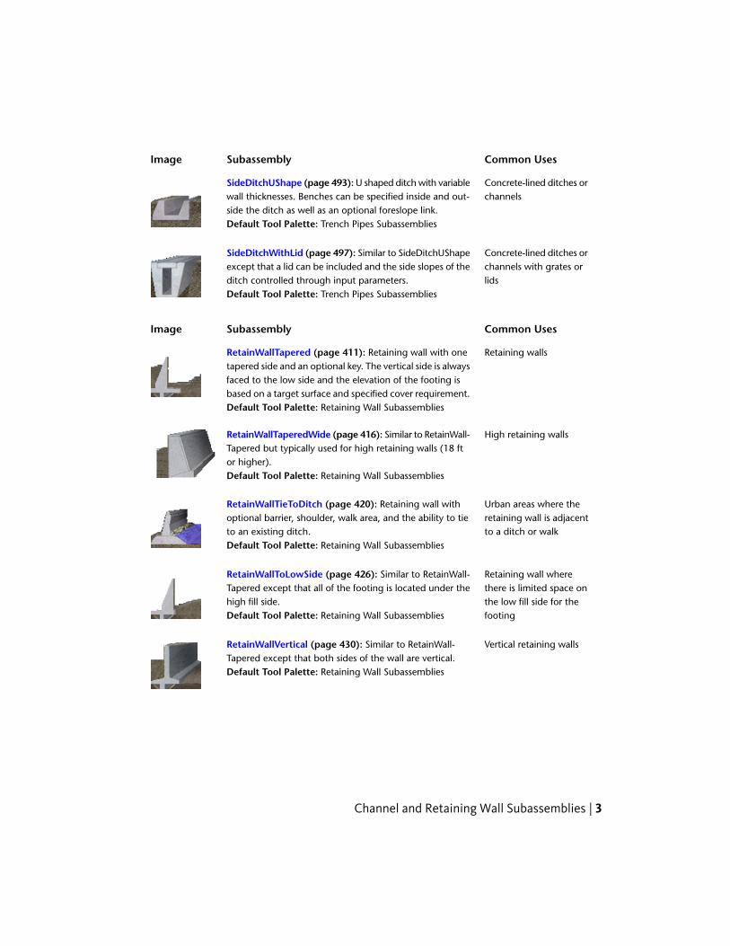
Concrete-lined ditches orchannels
SideDitchUShape (page 493): U shaped ditch with variablewall thicknesses. Benches can be specified inside and out-side the ditch as well as an optional foreslope link.Default Tool Palette: Trench Pipes Subassemblies
Concrete-lined ditches orchannels with grates orlids
SideDitchWithLid (page 497): Similar to SideDitchUShapeexcept that a lid can be included and the side slopes of theditch controlled through input parameters.Default Tool Palette: Trench Pipes Subassemblies
Common UsesSubassemblyImage
Retaining wallsRetainWallTapered (page 411): Retaining wall with onetapered side and an optional key. The vertical side is alwaysfaced to the low side and the elevation of the footing isbased on a target surface and specified cover requirement.Default Tool Palette: Retaining Wall Subassemblies
High retaining wallsRetainWallTaperedWide (page 416): Similar to RetainWall-Tapered but typically used for high retaining walls (18 ftor higher).Default Tool Palette: Retaining Wall Subassemblies
Urban areas where theretaining wall is adjacentto a ditch or walk
RetainWallTieToDitch (page 420): Retaining wall withoptional barrier, shoulder, walk area, and the ability to tieto an existing ditch.Default Tool Palette: Retaining Wall Subassemblies
Retaining wall wherethere is limited space on
RetainWallToLowSide (page 426): Similar to RetainWall-Tapered except that all of the footing is located under thehigh fill side. the low fill side for the
footingDefault Tool Palette: Retaining Wall Subassemblies
Vertical retaining wallsRetainWallVertical (page 430): Similar to RetainWall-Tapered except that both sides of the wall are vertical.Default Tool Palette: Retaining Wall Subassemblies
Channel and Retaining Wall Subassemblies | 3

Common UsesSubassemblyImage
Noise barriers or bermsSimpleNoiseBarrier (page 502): Creates a trapezoidal nosebarrier with the ability to tie the back of the barrier into anexisting surface. A topsoil thickness may be applied.Default Tool Palette: Retaining Wall Subassemblies
Generic SubassembliesUse these generic subassemblies to build assemblies.
Common UsesSubassemblyImage
Medians, curbs, other ir-regular structures
LinkMulti (page 257): General purpose subassembly to adda series of connected links.Default Tool Palette: Generic Subassemblies
General purposeLinkOffsetAndElevation (page 259): Creates a link fromthe attachment point to a user specified offset (from thebaseline) and elevation. Offset and elevation can be con-trolled by target parameters.Default Tool Palette: Generic Subassemblies
General purposeLinkOffsetAndSlope (page 262): Creates a link from theattachment point to a user specified offset (from thebaseline) at a given slope.Default Tool Palette: Generic Subassemblies
General purposeLinkOffsetOnSurface (page 265): Creates a link from theattachment point to a target surface at a given offset (fromthe baseline).Default Tool Palette: Generic Subassemblies
General purposeLinkSlopeAndVerticalDeflection (page 267): Creates a linkfrom the attachment point to a given vertical directionalong a given slope.Default Tool Palette: Generic Subassemblies
4 | Chapter 1 Subassembly Reference

Common UsesSubassemblyImage
Ditch between adjacentor merging roadways
LinkSlopesBetweenPoints (page 270): Creates intersectinglinks between the attachment point and a marked point.An optional ditch width can be assigned to create a flatlink in the middle.Default Tool Palette: Generic Subassemblies
General purposeLinkSlopeToElevation (page 272): Creates a link from theattachment point to a given elevation along a given slope.Default Tool Palette: Generic Subassemblies
Simple daylighting.LinkSlopeToSurface (page 275): Creates a link from theattachment point to a given surface along a given slope.Default Tool Palette: Generic Subassemblies
General purposeLinkToLaneMarker (page 278): Marks a point on a lanesubassembly from the attachment point to a specified widthand slope.Default Tool Palette: Generic Subassemblies
General purposeLinkToMarkedPoint (page 282): Creates a link from theattachment point to a marked point.Default Tool Palette: Generic Subassemblies
General purposeLinkVertical (page 287): Creates a vertical link from theattachment point to a given vertical deflection or profile.Default Tool Palette: Generic Subassemblies
General purposeLinkWidthAndSlope (page 289): Creates a link from theattachment point to a given width along a given slope.Default Tool Palette: Generic Subassemblies
Lot gradingLotGrade (page 292): Creates different lot grading vari-ations based on whether the general slope of the lot is upor down.Default Tool Palette: Generic Subassemblies
Generic Subassemblies | 5

Common UsesSubassemblyImage
General purposeMarkPoint (page 295): Creates a marked point which canbe targeted by certain subassemblies.Default Tool Palette: Generic Subassemblies
Basic SubassembliesUse these basic subassemblies to design assemblies.
Common UsesSubassemblyImage
Highway medians, trafficcontrol during construc-tion
BasicBarrier (page 18): A simple jersey barrier which canbe adjusted in size and shape through a number of para-meters.Default Tool Palette: Basic Subassemblies
Any road designBasicCurb (page 21): Simple rectangular curb.Default Tool Palette: Basic Subassemblies
All road and parking lotcurbing
BasicCurbAndGutter (page 23): A simple curb and gutterin which the height and width of the curb and gutter canbe adjusted through a number of parameters. The gutterslope can also be set. It is a "rigid" shape with no targetparameters.Default Tool Palette: Basic Subassemblies
Any road designBasicGuardrail (page 26): Simple guardrail structure.Default Tool Palette: Basic Subassemblies
Any road design wherethere is a constant lane
BasicLane (page 27): A simple lane with no subsurfacecourses. Available parameters control width, depth, andslope. It is a "rigid" shape with no target parameters. width and no material
volumes are neededDefault Tool Palette: Basic Subassemblies
6 | Chapter 1 Subassembly Reference
Common UsesSubassemblyImage
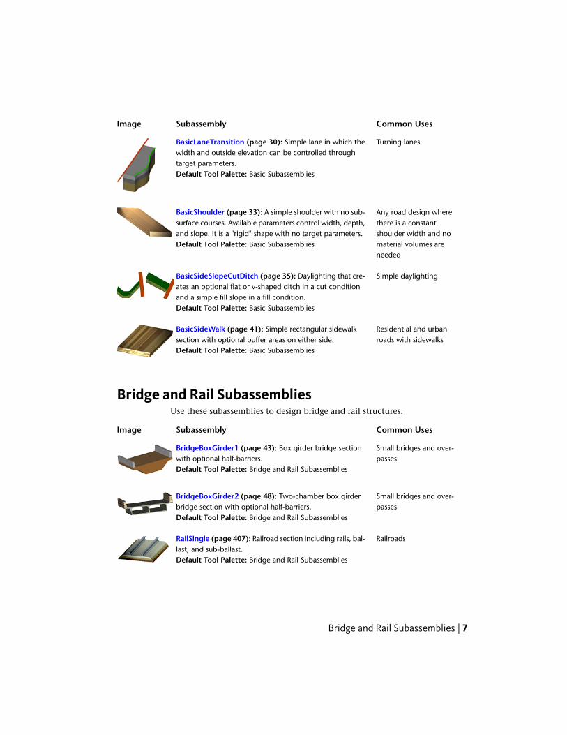
Turning lanesBasicLaneTransition (page 30): Simple lane in which thewidth and outside elevation can be controlled throughtarget parameters.Default Tool Palette: Basic Subassemblies
Any road design wherethere is a constant
BasicShoulder (page 33): A simple shoulder with no sub-surface courses. Available parameters control width, depth,and slope. It is a "rigid" shape with no target parameters. shoulder width and no
material volumes areneeded
Default Tool Palette: Basic Subassemblies
Simple daylightingBasicSideSlopeCutDitch (page 35): Daylighting that cre-ates an optional flat or v-shaped ditch in a cut conditionand a simple fill slope in a fill condition.Default Tool Palette: Basic Subassemblies
Residential and urbanroads with sidewalks
BasicSideWalk (page 41): Simple rectangular sidewalksection with optional buffer areas on either side.Default Tool Palette: Basic Subassemblies
Bridge and Rail SubassembliesUse these subassemblies to design bridge and rail structures.
Common UsesSubassemblyImage
Small bridges and over-passes
BridgeBoxGirder1 (page 43): Box girder bridge sectionwith optional half-barriers.Default Tool Palette: Bridge and Rail Subassemblies
Small bridges and over-passes
BridgeBoxGirder2 (page 48): Two-chamber box girderbridge section with optional half-barriers.Default Tool Palette: Bridge and Rail Subassemblies
RailroadsRailSingle (page 407): Railroad section including rails, bal-last, and sub-ballast.Default Tool Palette: Bridge and Rail Subassemblies
Bridge and Rail Subassemblies | 7

Daylight SubassembliesUse these subassemblies to add daylight to road assemblies.
Common UsesSubassemblyImage
Daylighting where abasin or ditch is required
DaylightBasin (page 79): Creates a basin in a cut situationor a basin, berm, and fill slope for a fill situation. Basin wallsare comprised of two slope segments whereas ditches onlycontain one.Default Tool Palette: Daylight Subassemblies
Daylighting where abasin or ditch is required
DaylightBasin2 (page 85): Similar to DaylightBasin exceptthat the berm is optional in a fill condition and the bermand basin widths can be controlled by an alignment.Default Tool Palette: Daylight Subassemblies
Large cut or fill slopeswhere benching is re-quired
DaylightBench (page 92): Creates cut of fill slopes withrepeating benches as needed.Default Tool Palette: Daylight Subassemblies
General purpose daylight-ing
DaylightGeneral (page 99): Generalized daylight solutionproviding many parameters to create a basin, ditch, orsimple daylight condition. It also includes an optionalguardrail.Default Tool Palette: Daylight Subassemblies
Deep cuts where multiplematerial types are en-countered
DaylightMultipleSurface (page 145): Allows varying cutslopes depending on the material type being excavated.Up to three surfaces can be specified (i.e. topsoil, clay,rock).Default Tool Palette: Daylight Subassemblies
Daylighting for deep cutsDaylightRockCut (page 149): Daylights using two targetsurfaces (existing ground and rock) with varied slope andditch solutions based on conditions encountered.Default Tool Palette: Daylight Subassemblies
8 | Chapter 1 Subassembly Reference

Common UsesSubassemblyImage
General purpose daylight-ing
DaylightStandard (page 156): Daylighting which appliesone of 3 preset slopes (Flat, Medium, and Steep) based onconditions. It creates a ditch in cut situations and an option-al guardrail for widening or steep fill conditions.Default Tool Palette: Daylight Subassemblies
Common UsesSubassemblyImage
Subdivision road daylight-ing
DaylightInsideROW (page 111): Daylights using a typicalslope as long as the daylight is within the ROW limits. Ifthe daylight falls outside the ROW, the slope can besteepened or held based on other parameters.Default Tool Palette: Daylight Subassemblies
Daylighting within aboundary or obstacle
DaylightMaxOffset (page 117): Typical slope is appliedunless a steeper slope is needed to stay within a maximumoffset from the baseline.Default Tool Palette: Daylight Subassemblies
Daylighting within aboundary or obstacle
DaylightMaxWidth (page 123): Similar to DaylightMaxOff-set except that the width of the daylight area is used insteadof an offset from the baseline.Default Tool Palette: Daylight Subassemblies
Daylighting outside of aboundary or obstacle
DaylightMinOffset (page 129): Typical slope is appliedunless a less steep slope is needed to stay outside of aminimum offset from the baseline.Default Tool Palette: Daylight Subassemblies
Daylighting outside of aboundary or obstacle
DaylightMinWidth (page 134): Similar to DaylightMinOff-set except that the width of the daylight area is used insteadof an offset from the baseline.Default Tool Palette: Daylight Subassemblies
Daylighting in "rough"terrain where a different
DaylightMultiIntercept (page 140): Daylighting that forcesthe cut or fill slope to pass through the surface multipletimes to intersect at a more distant location. intercept point may be
neededDefault Tool Palette: Daylight Subassemblies
Daylight Subassemblies | 9

Common UsesSubassemblyImage
Daylighting directly to aboundary or feature
DaylightToOffset (page 166): Daylights from the attach-ment point to a given offset from the baseline.Default Tool Palette: Daylight Subassemblies
Daylighting directly to aboundary or feature
DaylightToROW (page 171): Similar to DaylightToOffsetexcept that an offset adjustment can be applied so thatdaylighting occurs a given distance within or beyond theROW offset.Default Tool Palette: Daylight Subassemblies
Lane SubassembliesUse these subassemblies to design various types of lanes for road assemblies.
Common UsesSubassemblyImage
Crowned road wheresubgrade slope and
CrownedLane (page 74): A crowned lane with separatesubbase slope control and the ability to control the locationof the subbase crown. crown needs to be con-
trolled independentlyDefault Tool Palette: Lane Subassemblies
Any pavement courseGenericPavementStructure (page 181): A simple pavementstructure with user-definable point, link, and shape codes.Default Tool Palette: Lane Subassemblies
Highways with multiplelanes in one travel direc-tion
LaneBrokenBack (page 185): Two travel lanes with inde-pendent cross-slopes.Default Tool Palette: Lane Subassemblies
Multi-lane roads with su-perelevation
LaneInsideSuper (page 203): Lane that responds to InsideLane superelevation value.Default Tool Palette: Lane Subassemblies
10 | Chapter 1 Subassembly Reference
Common UsesSubassemblyImage
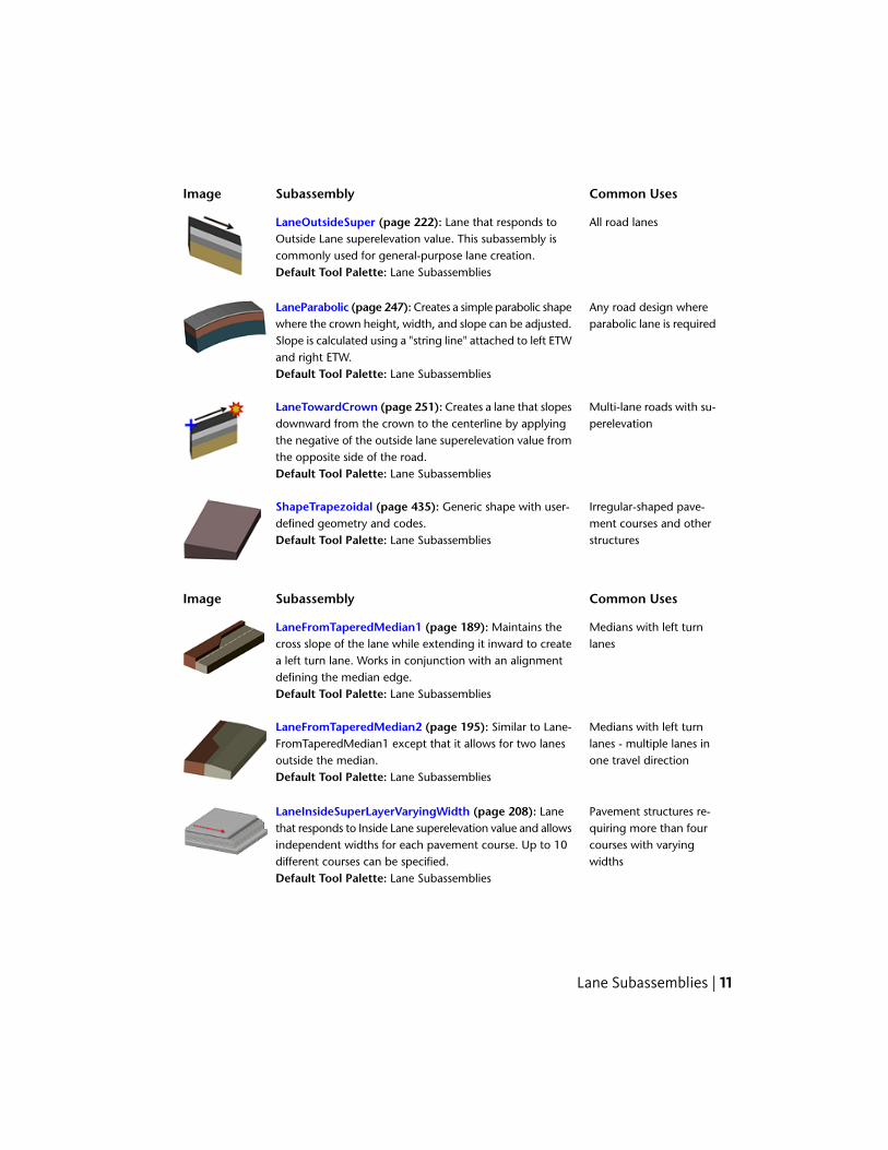
All road lanesLaneOutsideSuper (page 222): Lane that responds toOutside Lane superelevation value. This subassembly iscommonly used for general-purpose lane creation.Default Tool Palette: Lane Subassemblies
Any road design whereparabolic lane is required
LaneParabolic (page 247): Creates a simple parabolic shapewhere the crown height, width, and slope can be adjusted.Slope is calculated using a "string line" attached to left ETWand right ETW.Default Tool Palette: Lane Subassemblies
Multi-lane roads with su-perelevation
LaneTowardCrown (page 251): Creates a lane that slopesdownward from the crown to the centerline by applyingthe negative of the outside lane superelevation value fromthe opposite side of the road.Default Tool Palette: Lane Subassemblies
Irregular-shaped pave-ment courses and otherstructures
ShapeTrapezoidal (page 435): Generic shape with user-defined geometry and codes.Default Tool Palette: Lane Subassemblies
Common UsesSubassemblyImage
Medians with left turnlanes
LaneFromTaperedMedian1 (page 189): Maintains thecross slope of the lane while extending it inward to createa left turn lane. Works in conjunction with an alignmentdefining the median edge.Default Tool Palette: Lane Subassemblies
Medians with left turnlanes - multiple lanes inone travel direction
LaneFromTaperedMedian2 (page 195): Similar to Lane-FromTaperedMedian1 except that it allows for two lanesoutside the median.Default Tool Palette: Lane Subassemblies
Pavement structures re-quiring more than four
LaneInsideSuperLayerVaryingWidth (page 208): Lanethat responds to Inside Lane superelevation value and allows
courses with varyingwidths
independent widths for each pavement course. Up to 10different courses can be specified.Default Tool Palette: Lane Subassemblies
Lane Subassemblies | 11

Common UsesSubassemblyImage
Pavement structures re-quiring more than fourcourses
LaneInsideSuperMultiLayer (page 216): Similar toLaneInsideSuper except that there are additional availablepavement courses.Default Tool Palette: Lane Subassemblies
Pavement structures re-quiring more than four
LaneOutsideSuperLayerVaryingWidth (page 226): Lanethat responds to Outside Lane superelevation value and
courses with varyingwidths
allows independent widths for each pavement course. Upto 10 different courses can be specified.Default Tool Palette: Lane Subassemblies
Pavement structures re-quiring more than fourcourses
LaneOutsideSuperMultiLayer (page 235): Similar toLaneOutsideSuper except that there are additional availablepavement courses.Default Tool Palette: Lane Subassemblies
Highways where lanewidening is requiredwhen in superelevation
LaneOutsideSuperWithWidening (page 241): Automatic-ally widens lane in superelevated regions using a formulabased on the radius of the curve and the length of thewheelbase.Default Tool Palette: Lane Subassemblies
Median SubassembliesUse these subassemblies to add medians to road assemblies.
Common UsesSubassemblyImage
Divided roads or high-ways where asymmetric-al barriers are needed
MedianConstantSlopeWithBarrier (page 297): Flush me-dian with independent left and right jersey barriers andsubsurface courses that can be set to match the structureof abutting lanes.Default Tool Palette: Medians Subassemblies
Divided roads or high-ways requiring a de-pressed median
MedianDepressed (page 305): Depressed median betweenan attachment point and marked point with various para-meters to control ditch geometry.Default Tool Palette: Medians Subassemblies
12 | Chapter 1 Subassembly Reference

Common UsesSubassemblyImage
Divided roads or high-ways requiring a de-pressed median
MedianDepressedShoulderExt (page 309): DepressedMedian with various options for superelevation rotationand subgrade extension.Default Tool Palette: Medians Subassemblies
Divided roads or high-ways requiring a de-pressed median
MedianDepressedShoulderVert (page 316): Similar toMedianDepressedShoulderExt except that shoulder termin-ation is vertical rather than extending under the ditch slope.There is also a parameter to incorporate interior turn lanes.Default Tool Palette: Medians Subassemblies
Divided roads or high-ways
MedianFlushWithBarrier (page 323): Creates a medianthat is flush with adjacent lanes and can include an optionaljersey barrier. Subsurface courses that can be set to matchthe structure of abutting lanes.Default Tool Palette: Medians Subassemblies
Divided roads or high-ways where curbs definethe edges of the median
MedianRaisedConstantSlope (page 329): Creates a capfor a raised median between the attachment point and amarked point. The cross slope of the top of the median isconstant at a given section.Default Tool Palette: Medians Subassemblies
Divided roads or high-ways where curbs definethe edges of the median
MedianRaisedWithCrown (page 330): Similar to Median-RaisedConstantSlope except that the median cap iscrowned by applying slope values either manually orthrough superelevation.Default Tool Palette: Medians Subassemblies
Overlay and Stripping SubassembliesUse these subassemblies to add overlay and tripping to road assemblies.
Common UsesSubassemblyImage
Overlay of four-lane roadOverlayBrokenBackBetweenEdges (page 333): Creates afour-lane crowned overlay between existing gutter flangepoints on either side.Default Tool Palette: Rehab Subassemblies
Overlay and Stripping Subassemblies | 13

Common UsesSubassemblyImage
Overlay of four-lane roadOverlayBrokenBackOverGutters (page 340): Similar toOverlayBrokenBackBetweenEdges except that the overlayextends over the gutter to the curb flowline on each side.Default Tool Palette: Rehab Subassemblies
Resurfacing a road withpoor crown definition
OverlayCrownBetweenEdges (page 346): Creates acrowned road surface between two existing edges ofpavement.Default Tool Palette: Rehab Subassemblies
Widening a divided high-way to the inside
OverlayMedianAsymmetrical (page 351): Widens a dividedhighway by extending the travel lanes inward along theirexisting cross slopes. An asymmetrical barrier is providedthat resolves the elevation difference caused by extendingthe slopes inward.Default Tool Palette: Rehab Subassemblies
Widening a divided high-way to the inside
OverlayMedianSymmetrical (page 357): Similar to Over-layMedianAsymmetrical except that the cross slopes areadjusted so that the extend lanes meet at the centerline.Default Tool Palette: Rehab Subassemblies
Single lane pavementoverlay (not crowned)
OverlayMillAndLevel1 (page 363): Provides milling or lev-eling as needed, which is then topped with an overlay ofuser-specified depth. The overlay slope can be set to matchexisting, set to match superelevation, or entered manually.Default Tool Palette: Rehab Subassemblies
Two-lane pavementoverlay (crowned)
OverlayMillAndLevel2 (page 371): Similar to OverlayMil-lAndLevel1 except that it is intended for a crowned road-way. Rather than a single overlay slope, two slopes definethe crown of the road.Default Tool Palette: Rehab Subassemblies
Overlay of urban roadOverlayParabolic (page 380): Creates a parabolic overlaybetween two existing pavement edges.Default Tool Palette: Rehab Subassemblies
14 | Chapter 1 Subassembly Reference

Common UsesSubassemblyImage
Overlay and widen fromcurb inward
OverlayWidenFromCurb (page 385): Similar to Overlay-WidenMatchSlope1 except that it extends inward from acurb flange.Default Tool Palette: Rehab Subassemblies
Overlay and widen onone side
OverlayWidenMatchSlope1 (page 390): Overlays the ex-isting road, then provides widening at a cross slope thatmatches the existing road.Default Tool Palette: Rehab Subassemblies
Overlay and widen onboth sides
OverlayWidenMatchSlope2 (page 395): Similar to Over-layWidenMatchSlope1 except that it widens on two sides.Default Tool Palette: Rehab Subassemblies
Overlay and widen withsuperelevation
OverlayWidenWithSuper1 (page 401): Similar to Overlay-WidenMatchSlope1 except that the cross slope is set ac-cording to superelevation.Default Tool Palette: Rehab Subassemblies
Pavement removalStrippingPavement (page 507): Strips pavement to a givendepth starting at the attachment point and working inwardto the baseline.Default Tool Palette: Daylight Subassemblies
Topsoil removalStrippingTopSoil (page 511): Strips topsoil to a given depthfrom the attachment point to a given stripping width.Default Tool Palette: Daylight Subassemblies
Shoulder SubassembliesUse these subassemblies to add various types of shoulder shapes to roadassemblies.
Common UsesSubassemblyImage
Shoulders where allcourses extend to thedaylight slope
ShoulderExtendAll (page 439): Shoulder with all coursesextended to the daylight slope.Default Tool Palette: Shoulders Subassemblies
Shoulder Subassemblies | 15
Common UsesSubassemblyImage
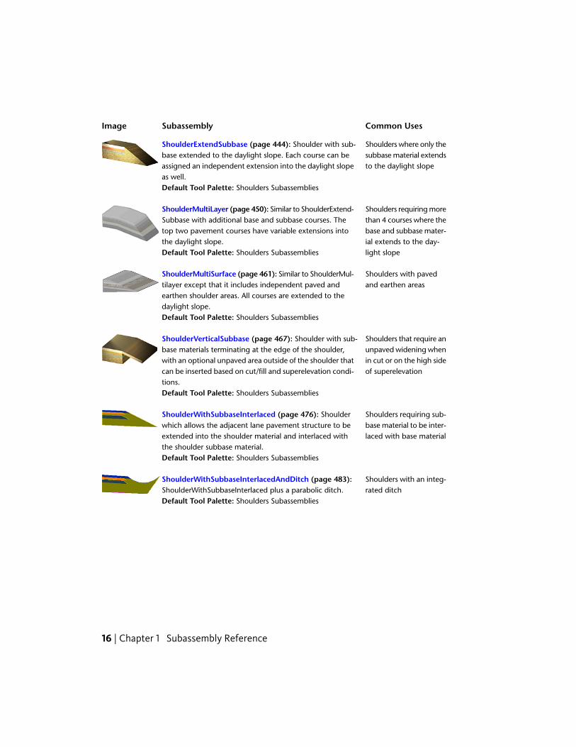
Shoulders where only thesubbase material extendsto the daylight slope
ShoulderExtendSubbase (page 444): Shoulder with sub-base extended to the daylight slope. Each course can beassigned an independent extension into the daylight slopeas well.Default Tool Palette: Shoulders Subassemblies
Shoulders requiring morethan 4 courses where the
ShoulderMultiLayer (page 450): Similar to ShoulderExtend-Subbase with additional base and subbase courses. The
base and subbase mater-ial extends to the day-light slope
top two pavement courses have variable extensions intothe daylight slope.Default Tool Palette: Shoulders Subassemblies
Shoulders with pavedand earthen areas
ShoulderMultiSurface (page 461): Similar to ShoulderMul-tilayer except that it includes independent paved andearthen shoulder areas. All courses are extended to thedaylight slope.Default Tool Palette: Shoulders Subassemblies
Shoulders that require anunpaved widening when
ShoulderVerticalSubbase (page 467): Shoulder with sub-base materials terminating at the edge of the shoulder,
in cut or on the high sideof superelevation
with an optional unpaved area outside of the shoulder thatcan be inserted based on cut/fill and superelevation condi-tions.Default Tool Palette: Shoulders Subassemblies
Shoulders requiring sub-base material to be inter-laced with base material
ShoulderWithSubbaseInterlaced (page 476): Shoulderwhich allows the adjacent lane pavement structure to beextended into the shoulder material and interlaced withthe shoulder subbase material.Default Tool Palette: Shoulders Subassemblies
Shoulders with an integ-rated ditch
ShoulderWithSubbaseInterlacedAndDitch (page 483):ShoulderWithSubbaseInterlaced plus a parabolic ditch.Default Tool Palette: Shoulders Subassemblies
16 | Chapter 1 Subassembly Reference

Urban SubassembliesUse these subassemblies to add curb, gutter, and sidewalk structures to roadassemblies that are typically used in urban design applications.
Common UsesSubassemblyImage
Urban or residentialcurbs
UrbanCurbGutterGeneral (page 529): Creates a standardcurb and gutter shape with input parameters for the dimen-sions. Also includes a subbase shape with user-definedsubbase slope and extension.Default Tool Palette: Curbs Subassemblies
Urban or residentialcurbs
UrbanCurbGutterValley1 (page 533): Creates a flat-bot-tomed valley curb and gutter shape with input parametersfor the dimensions. Also includes a subbase shape withuser-defined subbase slope and extension.Default Tool Palette: Curbs Subassemblies
Urban or residentialcurbs
UrbanCurbGutterValley2 (page 536): Similar to UrbanCurb-AndGutter-Valley1 except that the bottom is sloped.Default Tool Palette: Curbs Subassemblies
Urban or residentialcurbs
UrbanCurbGutterValley3 (page 540): Similar to UrbanCurb-AndGutter-Valley1 except that the bottom is sloped be-neath the gutter, then becomes flat beneath the curb.Default Tool Palette: Curbs Subassemblies
Curb replacementUrbanReplaceCurbGutter1 (page 544): Replaces an exist-ing curb and gutter and can tie the edge of a sod strip tothe existing inside edge of a sidewalk. Vertical placementof the curb is controlled by allowable mill and/or overlayand allowable ranges of slopes for the sod strip.Default Tool Palette: Curbs Subassemblies
Curb replacementUrbanReplaceCurbGutter2 (page 550): Similar to Urban-ReplaceCurbGutter1 except that the vertical placement ofthe curb is controlled by a profile.Default Tool Palette: Curbs Subassemblies
Sidewalk replacementUrbanReplaceSidewalk (page 556): Replaces an existingsidewalk by beginning at the outside edge and extendinginward at a given width and slope.Default Tool Palette: Curbs Subassemblies
Urban Subassemblies | 17

Common UsesSubassemblyImage
Urban or residential side-walks
UrbanSidewalk (page 560): Creates a concrete sidewalk ata given cross slope with inside and outside grass boulevards.Default Tool Palette: Curbs Subassemblies
Conditional SubassembliesUse these subassemblies to add conditional behavior to road assemblies in cutand fill situations.
Common UsesSubassemblyImage
General purposeConditionalCutOrFill (page 64): A special subassemblythat applies selected subassemblies based on whether thereis a cut or fill condition. It adds no actual geometric datato the assembly.Default Tool Palette: Conditional Subassemblies
General purposeConditionalHorizontalTarget (page 70): - A specialsubassembly that applies selected subassemblies based onwhether an offset target is found at the corridor station. Itadds no actual geometric data to the assembly.Default Tool Palette: Conditional Subassemblies
BasicBarrierThis subassembly creates a two-sided New Jersey barrier on a roadway surface.
This subassembly is one of a group of Getting Started subassemblies used forsimple roadway modeling, and for tutorial and training purposes.
18 | Chapter 1 Subassembly Reference

Attachment
The attachment point is at the center of the bottom of the barrier.
Input ParametersNote: All dimensions are in meters or feet unless otherwise noted. All slopesare in run-over-rise form (for example, 4 : 1) unless indicated as a percentslope with a “%” sign.
DefaultTypeDescriptionParameter
0.15 mNumeric, positiveWidth of the top of the barrierTop Width0.5 ft
0.225 mNumeric, positiveWidth of the middle of the barrierMiddle Width0.75 ft
0.6 mNumeric, positiveWidth of the bottom of the barrierBottom Width2.0 ft
0.9 mNumeric, positiveHeight to the top of the barrierTop Height3.0 ft
0.45 mNumeric, positiveHeight to the middle of the barrierMiddle Height1.5 ft
0.075 mNumeric, positiveHeight of the barrier curbCurb Height0.25 ft
BasicBarrier | 19

DefaultTypeDescriptionParameter
0.6 mNumeric, positiveWidth at the top of the barrier curbCurb Width1.9 ft
Output Parameters
None.
Target Parameters
This section lists the parameters in this subassembly that can be mapped toone or more target objects. For more information, see Setting Targets in theAutoCAD Civil 3D User’s Guide Help.
Target Parameters: None.
Behavior
The subassembly constructs the shape of a two-sided New Jersey barrier, withthe base centered about the attachment point.
Layout Mode Operation
In layout mode, this subassembly draws the barrier shape as specified by theinput parameters.
Point, Link, and Shape CodesThe following table lists the point, link, and shape codes for this subassemblythat have codes assigned to them. Point, link, or shape codes for thissubassembly that do not have codes assigned are not included in this table.
DescriptionCodesPoint, Link, or Shape
P1, P2, ... P8P1 - P8
BarrierAll links
BarrierS1
20 | Chapter 1 Subassembly Reference

Coding Diagram
BasicCurbThis subassembly creates a a simple curb at the edge of roadway. It can beattached to either outside edge of pavement or to the edge of a median onthe inside.
This subassembly is one of a group of Getting Started subassemblies used forsimple roadway modeling, and for tutorial and training purposes.
Attachment
The attachment point is on the front face of the curb for case 1, and on theback face of the curb for case 2.
BasicCurb | 21

Input ParametersNote: All dimensions are in meters or feet unless otherwise noted. All slopesare in run-over-rise form (for example, 4 : 1) unless indicated as a percentslope with a “%” sign.
DefaultTypeDescriptionParameter
RightLeft/RightSpecifies which side to place the sub-assembly
Side
0.225 mNumeric, posit-ive
Width of curbWidth0.75 ft
0.45 mNumeric, posit-ive
Depth of the curbDepth1.5 ft
Front FaceBooleanSpecifies the attachment point of thecurb as either Front Face or Back Face
Attachment Point
0.3 mNumeric, posit-ive
Depth of the curb below inside attach-ment point
Depth Below1.0 ft
0.0 mNumeric, posit-ive
Exposed height of the back face of curbBack Height0.0 ft
0 degreesAngularSpecified deflection of front face of thecurb. Specify zero degrees for verticalface.
Curb Face Deflection
YesBoolean:Yes/No
Sets the top of the curb perpendicularto the front face of the curb.
Apply Deflection toCurb Top
Target Parameters
This section lists the parameters in this subassembly that can be mapped toone or more target objects. For more information, see Setting Targets in theAutoCAD Civil 3D User’s Guide Help.
Target Parameters: None.
Output Parameters
None.
22 | Chapter 1 Subassembly Reference

Behavior
The subassembly builds a rectangular shape for a simple curb, with theattachment point at the bottom inside edge of curb.
Layout Mode Operation
In layout mode, this subassembly draws the curb shape as specified by theinput parameters.
Point, Link, and Shape CodesThe following table lists the point, link, and shape codes for this subassemblythat have codes assigned to them. Point, link, or shape codes for thissubassembly that do not have codes assigned are not included in this table.
DescriptionCodesPoint, Link, or Shape
Inside bottom of curbBottomCurbP1
Inside top of curbTopCurbP2
Outside top of curbBackCurbP3
CurbAll links
CurbS1
Coding Diagram
BasicCurbAndGutterThis subassembly creates a a simple curb and gutter structure at the inside oroutside edges of roadway.
BasicCurbAndGutter | 23

This subassembly is one of a group of Getting Started subassemblies used forsimple roadway modeling, and for tutorial and training purposes.
Attachment
The attachment point is at the flange point of the gutter or back of the curb.
Input ParametersNote: All dimensions are in meters or feet unless otherwise noted. All slopesare in run-over-rise form (for example, 4 : 1) unless indicated as a percentslope with a “%” sign.
DefaultTypeDescriptionParameter
RightLeft / RightSpecifies which side to place the sub-assembly
Side
GutterEdge
BooleanSpecifies insertion point of the curb andgutter as either Gutter Edge or Back ofCurb
Insertion Point
0.45 mNumeric, posit-ive
Width from the flange of the gutter tothe flowline
Gutter Width1.5 ft
-6%Numeric% slope of the gutterGutter %Slope
0.225 mNumeric, posit-ive
Height from the flowline to the top ofcurb
Curb Height0.75 ft
0.15 mNumeric, posit-ive
Width of the top of curbCurb Width0.5 ft
24 | Chapter 1 Subassembly Reference

DefaultTypeDescriptionParameter
0.45 mNumeric, posit-ive
Depth from the top of curb to the bot-tom of curb at the back-of-curb point
Curb Depth1.5 ft
Target Parameters
This section lists the parameters in this subassembly that can be mapped toone or more target objects. For more information, see Setting Targets in theAutoCAD Civil 3D User’s Guide Help.
Target Parameters: None.
Output Parameters
None.
Behavior
The subassembly builds the shape for a simple curb and gutter with theattachment point either at (a) the inside edge of the gutter (or lip), or (b) theback of the curb. The face of the curb is given a small, constant width to makeit non-vertical.
Layout Mode Operation
In layout mode, this subassembly draws the curb and gutter shape as specifiedby the input parameter values.
Point, Link, and Shape CodesThe following table lists the point, link, and shape codes for this subassemblythat have codes assigned to them. Point, link, or shape codes for thissubassembly that do not have codes assigned are not included in this table.
DescriptionCodesPoint, Link, or Shape
Flange of gutterFlangeP1
Flowline of the gutterFlowline_GutterP2
Top of curbTopCurbP3
Back of curbBackCurbP4
Curb links on finish gradeTop, CurbL1, L2, L3
BasicCurbAndGutter | 25
DescriptionCodesPoint, Link, or Shape
DatumL4
CurbS1
Coding Diagram
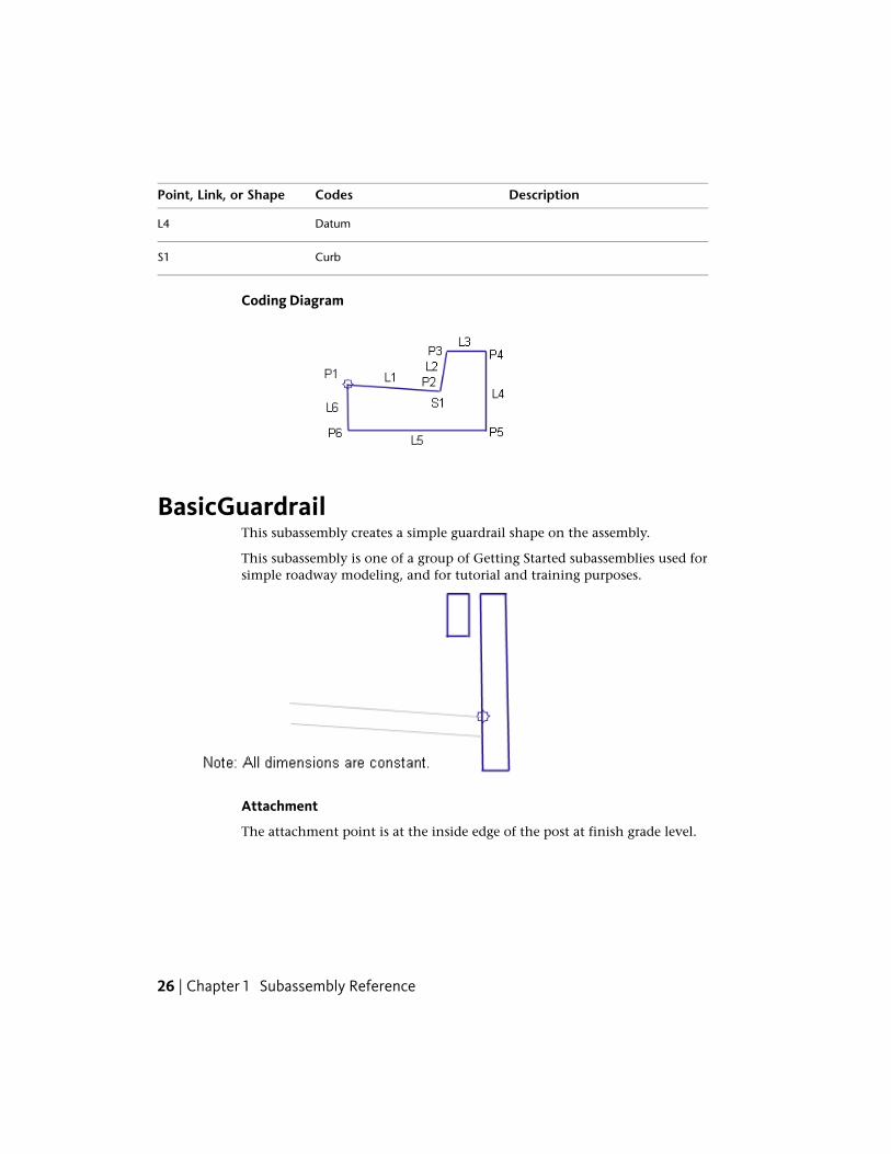
BasicGuardrailThis subassembly creates a simple guardrail shape on the assembly.
This subassembly is one of a group of Getting Started subassemblies used forsimple roadway modeling, and for tutorial and training purposes.
Attachment
The attachment point is at the inside edge of the post at finish grade level.
26 | Chapter 1 Subassembly Reference

Input ParametersNote: All dimensions are in meters or feet unless otherwise noted. All slopesare in run-over-rise form (for example, 4 : 1) unless indicated as a percentslope with a “%” sign.
DefaultTypeDescriptionParameter
RightLeft / RightSpecifies which side to place the sub-assembly
Side
Target Parameters
This section lists the parameters in this subassembly that can be mapped toone or more target objects. For more information, see Setting Targets in theAutoCAD Civil 3D User’s Guide Help.
Target Parameters: None.
Output Parameters
None.
Behavior
The subassembly builds two rectangular shapes for the post and railing. Thedimensions are fixed, and cannot be changed by the user. The post extendsdownward from the attachment point for a fixed distance below finish grade.
Layout Mode Operation
In layout mode, this subassembly draws the post and rail with the fixeddimensions.
Point, Link, and Shape Codes
The code “Guardrail” is assigned to all points. No link or shape codes areassigned.
BasicLaneThis subassembly creates a simple lane.
This subassembly is one of a group of Getting Started subassemblies used forsimple roadway modeling, and for tutorial and training purposes.
BasicLane | 27

Attachment
The attachment point is at the inside edge of lane on finish grade.
Input ParametersNote: All dimensions are in meters or feet unless otherwise noted. All slopesare in run-over-rise form (for example, 4 : 1) unless indicated as a percentslope with a “%” sign.
DefaultTypeDescriptionParameter
RightLeft / RightSpecifies which side to place the sub-assembly
Side
3.6 mNumeric, positiveWidth of the laneWidth12.0 ft
0.2 mNumeric, positiveDepth from finish grade to subbaseDepth0.67 ft
-2%Numeric% Slope of the lane%Slope
Target Parameters
This section lists the parameters in this subassembly that can be mapped toone or more target objects. For more information, see Setting Targets in theAutoCAD Civil 3D User’s Guide Help.
Target Parameters: None.
Output Parameters
TypeDescriptionParameter
Left / RightSpecifies which side to place the subassemblySide
28 | Chapter 1 Subassembly Reference

TypeDescriptionParameter
Numeric, positiveWidth of the laneWidth
Numeric, positiveDepth from finish grade to subbaseDepth
Numeric% Slope of the lane%Slope
Behavior
The subassembly builds a finish grade and subbase surface, closed by verticallinks at either end. The lane is inserted outward from the attachment pointfor the given width, depth, and slope.
Layout Mode Operation
In layout mode, this subassembly draws the lane using the input parameters.
Point, Link, and Shape CodesThe following table lists the point, link, and shape codes for this subassemblythat have codes assigned to them. Point, link, or shape codes for thissubassembly that do not have codes assigned are not included in this table.
DescriptionCodesPoint, Link, or Shape
Crown of road on finish gradeCrownP1
Edge-of-traveled-way on finish gradeETWP2
Crown of road on subbaseCrown_SubbaseP3
Edge-of-traveled-way on subbaseETW_SubbaseP4
Paved finish gradeTop, PaveL1
SubbaseDatum, SubbaseL3
Pave1S1
BasicLane | 29

Coding Diagram
BasicLaneTransitionThis subassembly creates a simple lane with finish grade and subbase, wherethe edge-of-traveled-way can be tied to an alignment or profile.
This subassembly is one of a group of Getting Started subassemblies used forsimple roadway modeling, and for tutorial and training purposes.
Attachment
The attachment point is either (a) at the inside edge of lane on finished grade,if the insertion point is Crown, or (b) at the outside edge of travel way,if theinsertion point is at the edge of travel way.
Input ParametersNote: All dimensions are in meters or feet unless otherwise noted. All slopesare in run-over-rise form (for example, 4 : 1) unless indicated as a percentslope with a “%” sign.
DefaultTypeDescriptionParameter
RightLeft / RightSpecifies which side to place thesubassembly
Side
30 | Chapter 1 Subassembly Reference

DefaultTypeDescriptionParameter
CrownList of options:Crown, Edge ofTravel Way
Specifies insertion point of the laneeither at the crown, or at the edgeof travel way
Insertion Point
YesYes / NoSpecifies that the inside edge oftravel way be coded as Crown
Crown Point on Inside
3.6 mNumeric, positiveWidth of laneWidth12.0 ft
0.2 mNumeric, positiveDepth from finish grade to subbaseDepth0.67 ft
-2%Numeric% Slope of the lane%Slope
Hold offsetand eleva-tion
MenuDescribes how the subassembly be-haves when an alignment, profile, orboth are used as target parameters.
Transition
Choices are provided in a list includ-ing:Hold offset and elevationHold elevation, change offsetHold grade, change offsetHold offset, change elevationChange offset and elevation
Target ParametersThis section lists the parameters in this subassembly that can be mapped toone or more target objects. For more information, see Setting Targets in theAutoCAD Civil 3D User’s Guide Help.
StatusDescriptionParameter
OptionalMay be used to override the fixed Width value andtie the edge-of-traveled-way to an offset. The follow-
Edge Offset
ing object types can be used as targets for specifyingthe offset: alignments, polylines, feature lines, or sur-vey figures.
OptionalMay be used to override the fixed slope and tie theedge-of-traveled-way to an elevation.The following
Edge Elevation
BasicLaneTransition | 31

StatusDescriptionParameter
object types can be used as targets for specifying theelevation: profiles, 3D polylines, feature lines, or surveyfigures.
Output Parameters
None.
BehaviorThis subassembly provides a simple travel lane that can tie to an alignmentfor variable width, and a profile for variable slope. The behavior depends onthe Transition type selected:
DescriptionTransition Type
The width and slope of the lane is held to the Width and %Slope input parameter values.
Hold offset and elevation
The elevation of the edge-of-traveled-way is calculated fromthe Width and % slope input parameter values. The width isthen tied to the offset alignment.
Hold elevation, change offset
The width is adjusted to tie to the offset alignment. The %Slope input value is held for the adjusted width.
Hold grade, change offset
The width is held to the Width input parameter value. Theelevation of the edge-of-traveled-way is tied to the offsetprofile.
Hold offset, change elevation
The width is tied to the offset alignment, and the slope isadjusted to tie the elevation of the edge-of-traveled-way tothe offset profile.
Change offset and elevation
Layout Mode Operation
In layout mode, this subassembly draws the lane using the input parameters.
32 | Chapter 1 Subassembly Reference

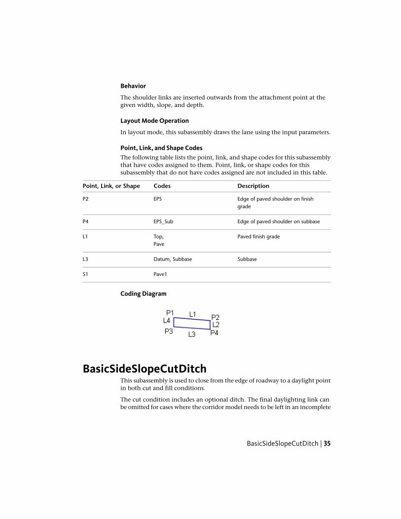
Point, Link, and Shape CodesThe following table lists the point, link, and shape codes for this subassemblythat have codes assigned to them. Point, link, or shape codes for thissubassembly that do not have codes assigned are not included in this table.
DescriptionCodesPoint, Link, or Shape
Crown of road on finish gradeCrownP1
Edge-of-traveled-way on finish gradeETWP2
Crown of road on subbaseCrown_SubbaseP3
Edge-of-traveled-way on subbaseETW_SubbaseP4
Paved finish gradeTop,L1Pave
SubbaseDatum,L3Subbase
Pave1S1
Coding Diagram
BasicShoulderThis subassembly creates a simple paved shoulder with finish grade andsubbase.
This subassembly is one of a group of Getting Started subassemblies used forsimple roadway modeling, and for tutorial and training purposes.
BasicShoulder | 33

Attachment
The attachment point is at the inside edge of the shoulder on the finish grade.
Input ParametersNote: All dimensions are in meters or feet unless otherwise noted. All slopesare in run-over-rise form (for example, 4 : 1) unless indicated as a percentslope with a “%” sign.
DefaultTypeDescriptionParameter
RightLeft / RightSpecifies which side to place the sub-assembly
Side
0.9 mNumeric, positiveWidth of shoulderWidth3 ft
0.2 mNumeric, positiveDepth from finish grade to subbaseDepth0.67 ft
-4%Numeric% Slope of the shoulder%Slope
Target Parameters
This section lists the parameters in this subassembly that can be mapped toone or more target objects. For more information, see Setting Targets in theAutoCAD Civil 3D User’s Guide Help.
Target Parameters: None.
Output Parameters
None.
34 | Chapter 1 Subassembly Reference
Behavior
The shoulder links are inserted outwards from the attachment point at thegiven width, slope, and depth.
Layout Mode Operation
In layout mode, this subassembly draws the lane using the input parameters.
Point, Link, and Shape CodesThe following table lists the point, link, and shape codes for this subassemblythat have codes assigned to them. Point, link, or shape codes for thissubassembly that do not have codes assigned are not included in this table.
DescriptionCodesPoint, Link, or Shape
Edge of paved shoulder on finishgrade
EPSP2
Edge of paved shoulder on subbaseEPS_SubP4
Paved finish gradeTop,L1Pave
SubbaseDatum, SubbaseL3
Pave1S1
Coding Diagram
BasicSideSlopeCutDitchThis subassembly is used to close from the edge of roadway to a daylight pointin both cut and fill conditions.
The cut condition includes an optional ditch. The final daylighting link canbe omitted for cases where the corridor model needs to be left in an incomplete
BasicSideSlopeCutDitch | 35
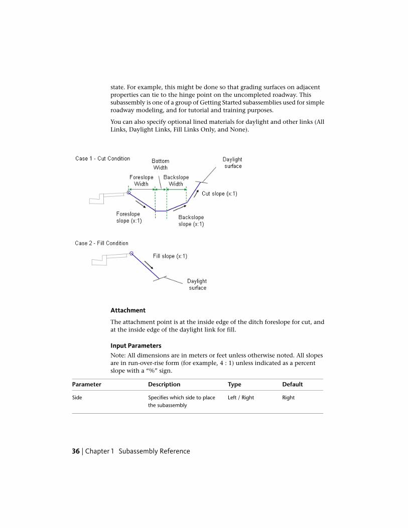
state. For example, this might be done so that grading surfaces on adjacentproperties can tie to the hinge point on the uncompleted roadway. Thissubassembly is one of a group of Getting Started subassemblies used for simpleroadway modeling, and for tutorial and training purposes.
You can also specify optional lined materials for daylight and other links (AllLinks, Daylight Links, Fill Links Only, and None).
Attachment
The attachment point is at the inside edge of the ditch foreslope for cut, andat the inside edge of the daylight link for fill.
Input ParametersNote: All dimensions are in meters or feet unless otherwise noted. All slopesare in run-over-rise form (for example, 4 : 1) unless indicated as a percentslope with a “%” sign.
DefaultTypeDescriptionParameter
RightLeft / RightSpecifies which side to placethe subassembly
Side
36 | Chapter 1 Subassembly Reference
DefaultTypeDescriptionParameter
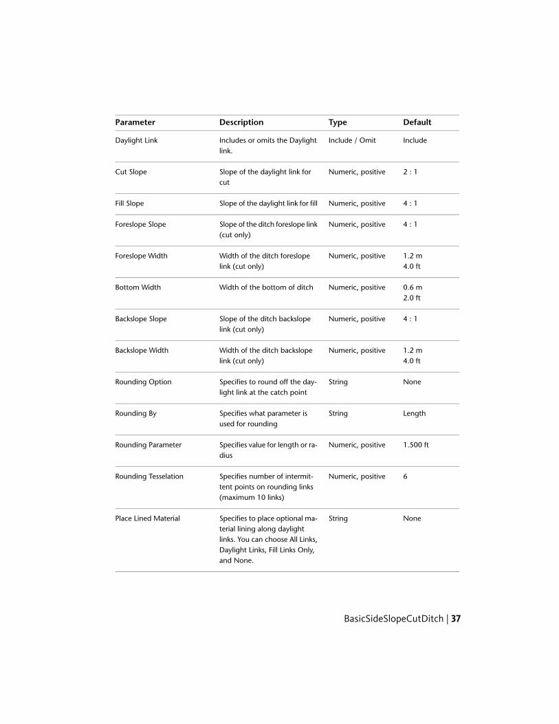
IncludeInclude / OmitIncludes or omits the Daylightlink.
Daylight Link
2 : 1Numeric, positiveSlope of the daylight link forcut
Cut Slope
4 : 1Numeric, positiveSlope of the daylight link for fillFill Slope
4 : 1Numeric, positiveSlope of the ditch foreslope link(cut only)
Foreslope Slope
1.2 mNumeric, positiveWidth of the ditch foreslopelink (cut only)
Foreslope Width4.0 ft
0.6 mNumeric, positiveWidth of the bottom of ditchBottom Width2.0 ft
4 : 1Numeric, positiveSlope of the ditch backslopelink (cut only)
Backslope Slope
1.2 mNumeric, positiveWidth of the ditch backslopelink (cut only)
Backslope Width4.0 ft
NoneStringSpecifies to round off the day-light link at the catch point
Rounding Option
LengthStringSpecifies what parameter isused for rounding
Rounding By
1.500 ftNumeric, positiveSpecifies value for length or ra-dius
Rounding Parameter
6Numeric, positiveSpecifies number of intermit-tent points on rounding links(maximum 10 links)
Rounding Tesselation
NoneStringSpecifies to place optional ma-terial lining along daylight
Place Lined Material
links. You can choose All Links,Daylight Links, Fill Links Only,and None.
BasicSideSlopeCutDitch | 37

DefaultTypeDescriptionParameter
1 : 1SlopeSpecifies the slope limit untilwhich the associated materiallining is placed
Slope Limit 1
12 inchesNumeric, positiveSpecifies the thickness of linedmaterial
Material 1 Thickness
Rip RapStringSpecifies the name of the ma-terial applies for lining alonggrading links
Material 1 Name
2 : 1SlopeSpecifies the slope limit untilwhich the associated materiallining is placed
Slope Limit 2
6 inchesNumeric, positiveSpecifies the thickness of linedmaterial
Material 2 Thickness
Rip RapStringSpecifies the name of the ma-terial applies for lining alonggrading links
Material 2 Name
4 : 1SlopeSpecifies the slope limit untilwhich the associated materiallining is placed
Slope Limit 3
4 inchesNumeric, positiveSpecifies the thickness of linedmaterial
Material 3 Thickness
Seeded GrassStringSpecifies the name of the ma-terial applies for lining alonggrading links
Material 3 Name
38 | Chapter 1 Subassembly Reference

Target ParametersThis section lists the parameters in this subassembly that can be mapped toone or more target objects. For more information, see Setting Targets in theAutoCAD Civil 3D User’s Guide Help.
StatusDescriptionParameter
RequiredName of the surface for daylighting. The following ob-ject types can be used as targets for specifying the sur-face: surfaces.
Daylight Surface
Output Parameters
None.
Behavior
The attachment point is tested to determine if it is in cut or fill. If it is in fill,the fill daylight link is extended to the Daylight Surface at the given Fill Slope.If in cut, the foreslope, ditch bottom, and backslope are added, and the cutdaylight link is extended from the end of the backslope to the Daylight Surfaceat the given Cut Slope.
This subassembly optionally lets you add a lined material. You can specifythree ranges of slopes. Material type 1 is applied if the slope of the links is upto the specified slope value. From slope 1 to slope 2, the second type of materialapplied. Similarly, if the slopes of links fall within slope 2 and slope 3 values,then material 3 is applied. If the link slopes are flatter than slope limit 3, thenno material is applied.
If a lined material is added to the subassembly, then parallel links are addedto the daylight links with specified thickness. Bottom level links are codedwith Datum and daylight links are coded with Top. Shapes enclosed by thesematerials are coded with material name.
Layout Mode Operation
In layout mode, this subassembly draws a generic cut and fill slope with arrowsat the ends.
BasicSideSlopeCutDitch | 39

Point, Link, and Shape CodesThe following table lists the point, link, and shape codes for this subassemblythat have codes assigned to them. Point, link, or shape codes for thissubassembly that do not have codes assigned are not included in this table.
DescriptionCodesPoint, Link, or Shape
Fill condition only - hinge point for fill daylightlink
HingeHinge_Fill
P1
Cut condition only - inside edge of ditchDitch_InP2Fill condition only - daylight pointDaylight
Daylight_Fill
Cut condition only - outside edge of ditchDitch_OutP3
Cut condition only - hinge point for cut daylightlink
Hinge_CutP4
Cut condition only - daylight pointDaylightP5Daylight_Cut
Unpaved finish gradeTopL1 - L4Datum
Daylight link in fillTopL1DatumDaylightDaylight_Fill
Daylight link in cutTopL4DatumDaylightDaylight_Cut
40 | Chapter 1 Subassembly Reference

Coding Diagram
BasicSideWalkThis subassembly is used to insert links defining a concrete sidewalk withoptional boulevards.
This is one of a group of Getting Started subassemblies used for simple roadwaymodeling, and for tutorial and training purposes.
Attachment
The attachment point is at the inside edge of the inside buffer.
BasicSideWalk | 41

Input ParametersNote: All dimensions are in meters or feet unless otherwise noted. All slopesare in run-over-rise form (for example, 4 : 1) unless indicated as a percentslope with a “%” sign.
DefaultTypeDescriptionParameter
RightLeft / RightIndicates which side the subassemblyis inserted toward
Side
1.8 mNumeric, positiveWidth of the concrete sidewalkWidth6.0 ft
0.1 mNumeric, positiveDepth of the concrete sidewalkDepth0.333 ft
0 ft, mNumeric, positiveWidth of the inside buffer zoneBuffer Width 1
0 ft, mNumeric, positiveWidth of the outside buffer zoneBuffer Width 2
Target Parameters
This section lists the parameters in this subassembly that can be mapped toone or more target objects. For more information, see Setting Targets in theAutoCAD Civil 3D User’s Guide Help.
Target Parameters: None.
Output Parameters
None.
Behavior
The links for the inside buffer zone, sidewalk, and outside buffer zone areinserted outward from the attachment point at a horizontal slope. The bufferzones may be omitted by setting their widths to zero.
Layout Mode Operation
In layout mode, this subassembly draws the buffer zone and sidewalk asspecified by the input parameters.
42 | Chapter 1 Subassembly Reference

Point, Link, and Shape CodesThe following table lists the point, link, and shape codes for this subassemblythat have codes assigned to them. Point, link, or shape codes for thissubassembly that do not have codes assigned are not included in this table.
DescriptionCodesPoint, Link, or Shape
Inside edge of sidewalk on finish gradeSidewalk_InP2
Outside edge of sidewalk on finish gradeSidewalk_OutP3
TopL1Datum
Sidewalk structure top linksTopL2Sidewalk
TopL3Datum
SidewalkL4 - L6Datum
Sidewalk concrete areaSidewalkS1
Coding Diagram
BridgeBoxGirder1This subassembly creates a simple box girder bridge shape with optionalhalf-barriers.
This subassembly is designed to be used for visualization, not for structuraldesign.
BridgeBoxGirder1 | 43

44 | Chapter 1 Subassembly Reference

Attachment
The attachment point is at the centerline on the bridge deck finish grade. Thebridge section is built to the left and right sides.
Input ParametersNote: All dimensions are in meters or feet unless otherwise noted. All slopesare in run-over-rise form (for example, 4 : 1) unless indicated as a percentslope with a “%” sign.
DefaultTypeDescriptionParameter
5.34 mNumeric, positiveWidth of the left side of the bridgedeck
Left Width17.8 ft
5.34 mNumeric, positiveWidth of the right side of thebridge deck
Right Width17.8 ft
Outside LaneSlope
List of options:No, Inside Lane
Specifies to use superelevationslope on the left side of thebridge.
Left - Use Superelevation
Slope, OutsideLane Slope
-2.0%NumericSpecifies default slope for the leftside of the bridge, if supereleva-tion slope is not specified.
Default Left Slope
Outside LaneSlope
List of options:No, Inside Lane
Specifies to use superelevationslope on the right side of thebridge.
Right - Use Superelevation
Slope, OutsideLane Slope
BridgeBoxGirder1 | 45

DefaultTypeDescriptionParameter
-2.0%NumericSpecifies default slope for the rightside of the bridge, if supereleva-tion slope is not specified.
Default Right Slope
2.0 mNumeric, positiveVertical distance from the edge ofbridge deck to the soffit
Soffit Depth6.67 ft
0.150 mNumeric, positiveThickness of the bridge deck atthe edge
Edge Depth0.5 ft
0.300 mNumeric, positiveVertical distance from the edge ofbridge deck to the root of theflange
Flange Depth1.0 ft
1.2 mNumeric, positiveWidth of the overhangOverhang Width4.0 ft
2.0 mNumeric, positiveWidth of the girderGirder Width6.67 ft
IncludeInclude / OmitIncludes or omits barriers to eachside of the bridge deck.
Include BarriersOmit Barriers
810 mmNumeric, positiveHeight of the barrier at the centerof median
Barrier A (mm or inches)32 in
131 mmNumeric, positiveAs shown in diagramBarrier B (mm or inches)4.5 in
59 mmNumeric, positiveAs shown in diagramBarrier C (mm or inches)2 in
125 mmNumeric, positiveAs shown in diagramBarrier D (mm or inches)5 in
557 mmNumeric, positiveAs shown in diagramBarrier E (mm or inches)22 in
178 mmNumeric, positiveAs shown in diagramBarrier F (mm or inches)7 in
46 | Chapter 1 Subassembly Reference
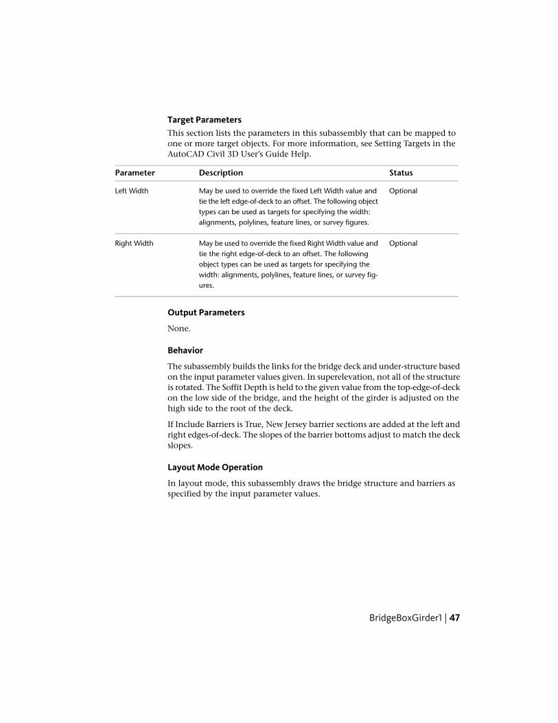
Target ParametersThis section lists the parameters in this subassembly that can be mapped toone or more target objects. For more information, see Setting Targets in theAutoCAD Civil 3D User’s Guide Help.
StatusDescriptionParameter
OptionalMay be used to override the fixed Left Width value andtie the left edge-of-deck to an offset. The following object
Left Width
types can be used as targets for specifying the width:alignments, polylines, feature lines, or survey figures.
OptionalMay be used to override the fixed Right Width value andtie the right edge-of-deck to an offset. The following
Right Width
object types can be used as targets for specifying thewidth: alignments, polylines, feature lines, or survey fig-ures.
Output Parameters
None.
Behavior
The subassembly builds the links for the bridge deck and under-structure basedon the input parameter values given. In superelevation, not all of the structureis rotated. The Soffit Depth is held to the given value from the top-edge-of-deckon the low side of the bridge, and the height of the girder is adjusted on thehigh side to the root of the deck.
If Include Barriers is True, New Jersey barrier sections are added at the left andright edges-of-deck. The slopes of the barrier bottoms adjust to match the deckslopes.
Layout Mode Operation
In layout mode, this subassembly draws the bridge structure and barriers asspecified by the input parameter values.
BridgeBoxGirder1 | 47

Point, Link, and Shape CodesThe following table lists the point, link, and shape codes for this subassemblythat have codes assigned to them. Point, link, or shape codes for thissubassembly that do not have codes assigned are not included in this table.
DescriptionCodesPoint, Link, or Shape
Edge of bridge deckEBDP1, P3
Crown point on bridge deckCrown_DeckP2
Deck, TopL1, L2
Bridge substructure linksBridgeL3 – L9
BarrierAll barrier links
BridgeS1
BarrierS2, S3
Coding Diagram
BridgeBoxGirder2This subassembly creates a two-chamber box girder bridge shape with optionalhalf-barriers.
This subassembly is designed to be used for visualization, not for structuraldesign.
48 | Chapter 1 Subassembly Reference

Attachment
The attachment point is at the dividing line between the left and right lanes,on the bridge deck finish grade. The bridge section is built to the left and rightsides.
Input ParametersNote: All dimensions are in meters or feet unless otherwise noted. All slopesare in run-over-rise form (for example, 4 : 1) unless indicated as a percentslope with a “%” sign.
DefaultTypeDescriptionParameter
5.34 mNumeric, posit-ive
Width of the left lanes of thebridge deck
Left Lane Width17.8 ft
5.34 mNumeric, posit-ive
Width of the right lanes of thebridge deck
Right Lane Width17.8 ft
BridgeBoxGirder2 | 49
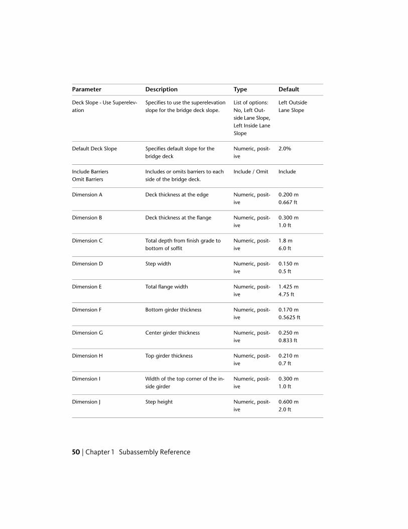
DefaultTypeDescriptionParameter
Left OutsideLane Slope
List of options:No, Left Out-
Specifies to use the superelevationslope for the bridge deck slope.
Deck Slope - Use Superelev-ation
side Lane Slope,Left Inside LaneSlope
2.0%Numeric, posit-ive
Specifies default slope for thebridge deck
Default Deck Slope
IncludeInclude / OmitIncludes or omits barriers to eachside of the bridge deck.
Include BarriersOmit Barriers
0.200 mNumeric, posit-ive
Deck thickness at the edgeDimension A0.667 ft
0.300 mNumeric, posit-ive
Deck thickness at the flangeDimension B1.0 ft
1.8 mNumeric, posit-ive
Total depth from finish grade tobottom of soffit
Dimension C6.0 ft
0.150 mNumeric, posit-ive
Step widthDimension D0.5 ft
1.425 mNumeric, posit-ive
Total flange widthDimension E4.75 ft
0.170 mNumeric, posit-ive
Bottom girder thicknessDimension F0.5625 ft
0.250 mNumeric, posit-ive
Center girder thicknessDimension G0.833 ft
0.210 mNumeric, posit-ive
Top girder thicknessDimension H0.7 ft
0.300 mNumeric, posit-ive
Width of the top corner of the in-side girder
Dimension I1.0 ft
0.600 mNumeric, posit-ive
Step heightDimension J2.0 ft
50 | Chapter 1 Subassembly Reference

DefaultTypeDescriptionParameter
810 mmNumeric, posit-ive
Height of the barrier at the centerof median
Barrier A (mm or inches)32 in
131 mmNumeric, posit-ive
As shown in diagramBarrier B (mm or inches)4.5 in
59 mmNumeric, posit-ive
As shown in diagramBarrier C (mm or inches)2 in
125 mmNumeric, posit-ive
As shown in diagramBarrier D (mm or inches)5 in
557 mmNumeric, posit-ive
As shown in diagramBarrier E (mm or inches)22 in
178 mmNumeric, posit-ive
As shown in diagramBarrier F (mm or inches)7 in
Target ParametersThis section lists the parameters in this subassembly that can be mapped toone or more target objects. For more information, see Setting Targets in theAutoCAD Civil 3D User’s Guide Help.
StatusDescriptionParameter
OptionalMay be used to override the fixed Left Width and tie theleft edge-of-deck to an offset. The following object types
Left Width
can be used as targets for specifying the width: alignments,polylines, feature lines, or survey figures..
OptionalMay be used to override the fixed Right Width and tie theright edge-of-deck to an offset alignment at each station
Right Width
along the corridor. The following object types can be usedas targets for specifying the width: alignments, polylines,feature lines, or survey figures.
Output Parameters
None.
BridgeBoxGirder2 | 51

Behavior
The subassembly builds the links for the bridge deck and under-structure basedon the input parameter values given. If the LI or LO options are used for thebridge deck, the superelevation slope for the left side is held constant acrossthe entire width of the bridge.
If Include Barriers is True, one-sided New Jersey barrier sections are added atthe left and right edges-of-deck. The slopes of the barrier bottoms adjust tomatch the deck slopes.
Layout Mode Operation
In layout mode, this subassembly draws the bridge structure and barriers asspecified by the input parameter values.
Point, Link, and Shape CodesThe following table lists the point, link, and shape codes for this subassemblythat have codes assigned to them. Point, link, or shape codes for thissubassembly that do not have codes assigned are not included in this table.
DescriptionCodePoint, Link, or Shape
Edge of bridge deckEBDP1, P3
Crown point on bridge deckCrown_DeckP2
Deck, TopL1
All exterior bridge substructure linksBridge
All interior bridge substructure linksGirder
BarrierAll barrier links
BridgeS1
BarrierS2, S3
52 | Chapter 1 Subassembly Reference

Coding Diagram
ChannelThis subassembly creates an open channel with optional lining and backslopelinks.
Channel | 53
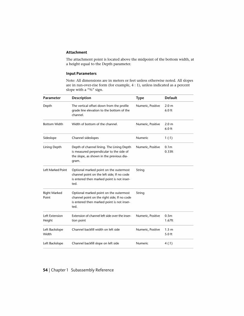
Attachment
The attachment point is located above the midpoint of the bottom width, ata height equal to the Depth parameter.
Input Parameters
Note: All dimensions are in meters or feet unless otherwise noted. All slopesare in run-over-rise form (for example, 4 : 1), unless indicated as a percentslope with a “%” sign.
DefaultTypeDescriptionParameter
2.0 mNumeric, PositiveThe vertical offset down from the profilegrade line elevation to the bottom of thechannel.
Depth6.0 ft
2.0 mNumeric, PositiveWidth of bottom of the channel.Bottom Width6.0 ft
1 (:1)NumericChannel sideslopesSideslope
0.1mNumeric, PositiveDepth of channel lining. The Lining Depthis measured perpendicular to the side of
Lining Depth0.33ft
the slope, as shown in the previous dia-gram.
StringOptional marked point on the outermostchannel point on the left side; If no code
Left Marked Point
is entered then marked point is not inser-ted.
StringOptional marked point on the outermostchannel point on the right side; If no code
Right MarkedPoint
is entered then marked point is not inser-ted.
0.5mNumeric, PositiveExtension of channel left side over the inser-tion point
Left ExtensionHeight 1.67ft
1.5 mNumeric, PositiveChannel backfill width on left sideLeft BackslopeWidth 5.0 ft
4 (:1)NumericChannel backfill slope on left sideLeft Backslope
54 | Chapter 1 Subassembly Reference

DefaultTypeDescriptionParameter
0.5 mNumeric, PositiveExtension of channel right side over theinsertion point
Right ExtensionHeight 1.67 ft
1.5 mNumeric, PositiveChannel backfill width on the right sideRight BackslopeWidth 5.0 ft
4 (:1)NumericChannel backfill slope on right sideRight Backslope
Target ParametersThis section lists the parameters in this subassembly that can be mapped toone or more target objects. For more information, see Setting Targets in theAutoCAD Civil 3D User’s Guide Help.
StatusDescriptionParameter
OptionalMay be used to override the fixed extension height on leftside and tie to a profile. The following object types can be
Left Extension Height
used as targets for specifying the elevation: profiles, 3Dpolylines, feature lines, or survey figures.
OptionalMay be used to override the fixed Left Backslope Widthand tie to an offset alignment. The following object types
Left Backslope Width
can be used as targets for specifying the width: alignments,polylines, feature lines, or survey figures.
OptionalMay be used to override the fixed Left Backslope and tieto a profile. The following object types can be used as
Left Backslope Eleva-tion
targets for specifying the elevation: profiles, 3D polylines,feature lines, or survey figures.
OptionalMay be used to override the fixed extension height onright side and tie to a profile.The following object types
Right ExtensionHeight
can be used as targets for specifying this: profiles, 3Dpolylines, feature lines, or survey figures.
OptionalMay be used to override the fixed Right Backslope Widthand tie to an offset alignment. The following object types
Left Backslope Width
can be used as targets for specifying the width: alignments,polylines, feature lines, or survey figures.
Channel | 55

StatusDescriptionParameter
OptionalMay be used to override the fixed Right Backslope and tieto a profile. The following object types can be used as
Left Backslope Eleva-tion
targets for specifying this: profiles, 3D polylines, featurelines, or survey figures.
Output Parameters
None.
Behavior
This subassembly builds an open channel shape using the input parameters.The attachment point is typically at the start of the baseline, at associatedalignments and profiles. The bottom link of the channel is then drawn usinga specified width. Using the sideslope parameter, the channel sides are drawnon either sides.
For the channel lining depth, if a non-zero positive value is specified for theLining Depth parameter, then a material lining is drawn around the channel.The Lining Depth is measured perpendicular to the side of the slope, as shownin the previous diagram. If a zero value is specified for the Lining Depth, thenno links are inserted.
Similarly, if a zero value is specified for left or right extensions and backslopewidths, those links are omitted, or are not drawn. Extension height can becontrolled with a target parameter profile association. Similarly, the heightof the backslope end point can be specified to a profile. To force the outerbackslope point to the channel top elevation, associate this point to thechannel’s finish grade profile, to which this assembly is attached.
If the Backslope Width is omitted, the Right Marked Point is located on theouter point of channel height extension. If the Channel Height Extensionlink is also omitted, then the marked point is located on the outermost pointon the channel top.
NOTE In Civil 3D 2010 and previous versions, the Lining Depth parameter wasmeasured vertically. In Civil 3D 2011 and later, this parameter is measuredperpendicular to the side slope. Therefore, if you open a drawing containing thesesubassemblies that was created in Civil 3D 2010 or prior in Civil 3D 2011 or later,and then rebuild the corridor(s), this parameter will be changed to reflect the newbehavior. Any volume reports that use this subassembly will be updated to reflectthe new behavior.
56 | Chapter 1 Subassembly Reference
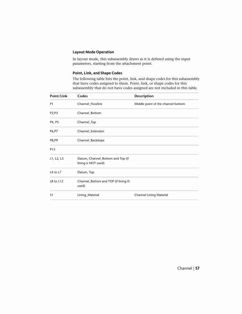
Layout Mode Operation
In layout mode, this subassembly draws as it is defined using the inputparameters, starting from the attachment point.
Point, Link, and Shape CodesThe following table lists the point, link, and shape codes for this subassemblythat have codes assigned to them. Point, link, or shape codes for thissubassembly that do not have codes assigned are not included in this table.
DescriptionCodesPoint/Link
Middle point of the channel bottomChannel_FlowlineP1
Channel_BottomP2,P3
Channel_TopP4, P5
Channel_ExtensionP6,P7
Channel_BackslopeP8,P9
P13
Datum, Channel_Bottom and Top (iflining is NOT used)
L1, L2, L3
Datum, TopL4 to L7
Channel_Bottom and TOP (if lining ISused)
L8 to L12
Channel Lining MaterialLining_MaterialS1
Channel | 57

Coding Diagram
ChannelParabolicBottomThis subassembly creates an open channel with a parabolic bottom, withoptional lining and backslope links.
58 | Chapter 1 Subassembly Reference

Attachment
The attachment point is located above the midpoint of the bottom width, ata height equal to the Depth parameter.
Input Parameters
Note: All dimensions are in meters or feet unless otherwise noted. All slopesare in run-over-rise form (for example, 4 : 1), unless indicated as a percentslope with a “%” sign.
DefaultTypeDescriptionParameter
2.0 mNumeric, PositiveThe vertical offset down from theprofile grade line elevation to thebottom of the channel.
Depth6.0 ft
2.0 mNumeric, PositiveWidth of bottom of the channel.Bottom Width6.0 ft
7Integer, PositiveNumber of tesselation points onparabolic curve
Curve TesselationPoints
1 (:1)NumericChannel sideslopesSideslope
0.1 mNumeric, PositiveDepth of channel lining. The LiningDepth is measured perpendicular to
Lining Depth0.33 ft
ChannelParabolicBottom | 59

DefaultTypeDescriptionParameter
the side of the slope, as shown in theprevious diagram.
StringOptional marked point on the outer-most channel point on the left side;
Left Marked Point
If no code is entered then markedpoint is not inserted.
StringOptional marked point on the outer-most channel point on the right side;
Right Marked Point
If no code is entered then markedpoint is not inserted.
0.5 mNumeric, PositiveExtension of channel left side overthe insertion point
Left Extension Height1.67 ft
1.5 mNumeric, PositiveChannel backfill width on left sideLeft Backslope Width5.0 ft
4 (:1)NumericChannel backfill slope on left sideLeft Backslope
0.5 mNumeric, PositiveExtension of channel right side overthe insertion point
Right Extension Height1.67 ft
1.25 mNumeric, PositiveChannel backfill width on the rightside
Right Backslope Width5.0 ft
4 (:1)NumericChannel backfill slope on right sideRight Backslope
Target ParametersThis section lists the parameters in this subassembly that can be mapped toone or more target objects. For more information, see Setting Targets in theAutoCAD Civil 3D User’s Guide Help.
StatusDescriptionParameter
OptionalMay be used to override the fixed extensionheight on left side and tie to a profile. The follow-
Left Extension Height
ing object types can be used as targets for spe-cifying the elevation: profiles, 3D polylines, fea-ture lines, or survey figures.
60 | Chapter 1 Subassembly Reference

StatusDescriptionParameter
OptionalMay be used to override the fixed Left BackslopeWidth and tie to an offset alignment. The follow-
Left Backslope Width
ing object types can be used as targets for spe-cifying the width: alignments, polylines, featurelines, or survey figures.
OptionalMay be used to override the fixed Left Backslopeand tie to a profile. The following object types
Left Backslope Elevation
can be used as targets for specifying the eleva-tion: profiles, 3D polylines, feature lines, or sur-vey figures.
OptionalMay be used to override the fixed extensionheight on right side and tie to a profile. The fol-
Right Extension Height
lowing object types can be used as targets forspecifying the elevation: profiles, 3D polylines,feature lines, or survey figures.
OptionalMay be used to override the fixed Right Back-slope Width and tie to an offset alignment. The
Left Backslope Width
following object types can be used as targets forspecifying the width: alignments, polylines, fea-ture lines, or survey figures.
OptionalMay be used to override the fixed Right Back-slope and tie to a profile. The following object
Left Backslope Elevation
types can be used as targets for specifying theelevation: profiles, 3D polylines, feature lines, orsurvey figures.
Output Parameters
None.
Behavior
This subassembly builds an open channel shape using the input parameters.The attachment point is typically at the start of the baseline, at associatedalignments and profiles. At the bottom left and right lower sideslope link,points are located using a specified Bottom Width parameter. A paraboliccurve is drawn between these two points with grade-in and grade-out equalto the specified sideslope parameter. The length of the parabolic curve is equal
ChannelParabolicBottom | 61

to the Bottom Width value. This parabolic curve is drawn in tessellated linksusing the Curve Tessellation Points parameter. If the tessellation index is odd,then a point is added directly below the attachment point of the subassembly.
For the channel lining depth, if a non-zero positive value is specified for theLining Depth parameter, then a material lining is drawn around the channel.The Lining Depth is measured perpendicular to the side of the slope, as shownin the previous diagram. If a zero value is specified for the Lining Depth, thenno links are inserted.
Similarly, if a zero value is specified for left or right extensions and backslopewidths, those links are omitted or are not drawn. Extension height can becontrolled with a profile target parameter association. Similarly, the heightof the outermost backslope point can be specified with a profile targetparameter. To force the outermost backslope point to the channel top height,associate this to the channel’s finish grade profile, to which this assembly isattached.
If the Backslope Width is omitted, then the marked point is located on theouter point of the channel height extension. If the Channel Height Extensionlink is also omitted, then the marked point is located on the outermost pointof the channel top.
NOTE In Civil 3D 2010 and previous versions, the Lining Depth parameter wasmeasured vertically. In Civil 3D 2011 and later, this parameter is measuredperpendicular to the side slope. Therefore, if you open a drawing containing thesesubassemblies that was created in Civil 3D 2010 or prior in Civil 3D 2011 or later,and then rebuild the corridor(s), this parameter will be changed to reflect the newbehavior. Any volume reports that use this subassembly will be updated to reflectthe new behavior.
Layout Mode Operation
In layout mode, this subassembly draws as it is defined using the inputparameters, starting from the attachment point.
Point, Link, and Shape CodesThe following table lists the point, link, and shape codes for this subassemblythat have codes assigned to them. Point, link, or shape codes for thissubassembly that do not have codes assigned are not included in this table.
DescriptionCodesPoint/Link
Middle point of the channel bottomChannel_FlowlineP1
62 | Chapter 1 Subassembly Reference

DescriptionCodesPoint/Link
Channel_BottomP2,P3
Channel_TopP4, P5
Channel_ExtensionP6,P7
Channel_BackslopeP8,P9
P13
Datum, Channel_Bottom andTop (if lining is NOT used)
L1, L2, L3
Datum, TopL4 to L7
Channel_Bottom and TOP (iflining IS used)
L8 to L12
Channel Lining MaterialLining_MaterialS1
Coding Diagram
ChannelParabolicBottom | 63

ConditionalCutOrFillThis subassembly automatically applies various subassemblies, such as genericlinks, widening, ditching, or daylighting subassemblies, to an assembly basedon whether a cut or fill condition exists.
The ConditionalCutOrFill subassembly is a special type of subassembly thatis referred to as a conditional subassembly. Conditional subassembliesautomatically add specified subassemblies to an assembly when certainconditions, which you specify, exist.
For example, when an assembly contains a ConditionalCutOrFill subassembly,AutoCAD Civil 3D analyzes the station, offset, and elevation position of thesubassembly to determine whether it is in cut or fill condition. Depending onhow you set the ConditionalCutOrFill subassembly parameters, different typesof subsequent subassemblies are automatically applied (added) to the assemblybased on whether the subassembly is in cut or fill.
To learn more about how to use the ConditionalCutOrFill subassembly, seethe Tutorial: Creating an Assembly with Conditions tutorial.
The following illustration shows a corridor assembly section comprised of:
■ a left and a right side lane
■ four ConditionalCutOrFill subassemblies (two on the left side and two onthe righ side)
■ The top left side ConditionalCutOrFill subassembly is configured toautomatically add a Bench subassembly when AutoCAD Civil 3D detectsthat the assembly is in a cut condition.
64 | Chapter 1 Subassembly Reference
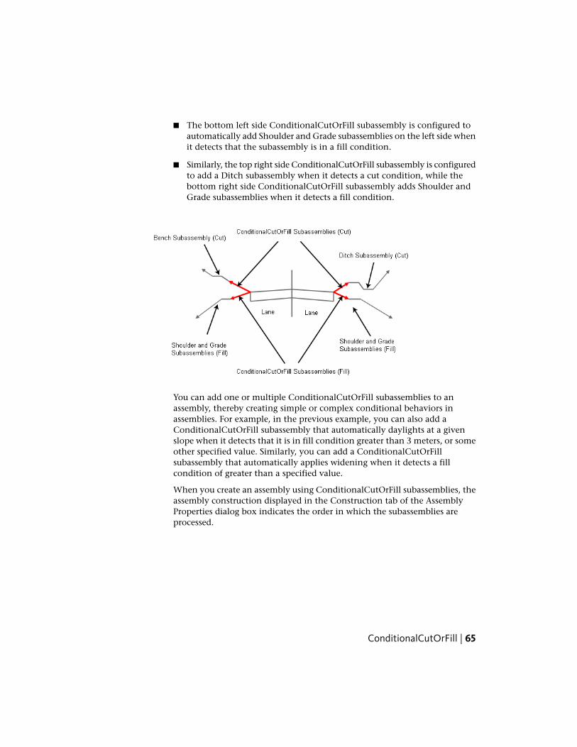
■ The bottom left side ConditionalCutOrFill subassembly is configured toautomatically add Shoulder and Grade subassemblies on the left side whenit detects that the subassembly is in a fill condition.
■ Similarly, the top right side ConditionalCutOrFill subassembly is configuredto add a Ditch subassembly when it detects a cut condition, while thebottom right side ConditionalCutOrFill subassembly adds Shoulder andGrade subassemblies when it detects a fill condition.
You can add one or multiple ConditionalCutOrFill subassemblies to anassembly, thereby creating simple or complex conditional behaviors inassemblies. For example, in the previous example, you can also add aConditionalCutOrFill subassembly that automatically daylights at a givenslope when it detects that it is in fill condition greater than 3 meters, or someother specified value. Similarly, you can add a ConditionalCutOrFillsubassembly that automatically applies widening when it detects a fillcondition of greater than a specified value.
When you create an assembly using ConditionalCutOrFill subassemblies, theassembly construction displayed in the Construction tab of the AssemblyProperties dialog box indicates the order in which the subassemblies areprocessed.
ConditionalCutOrFill | 65
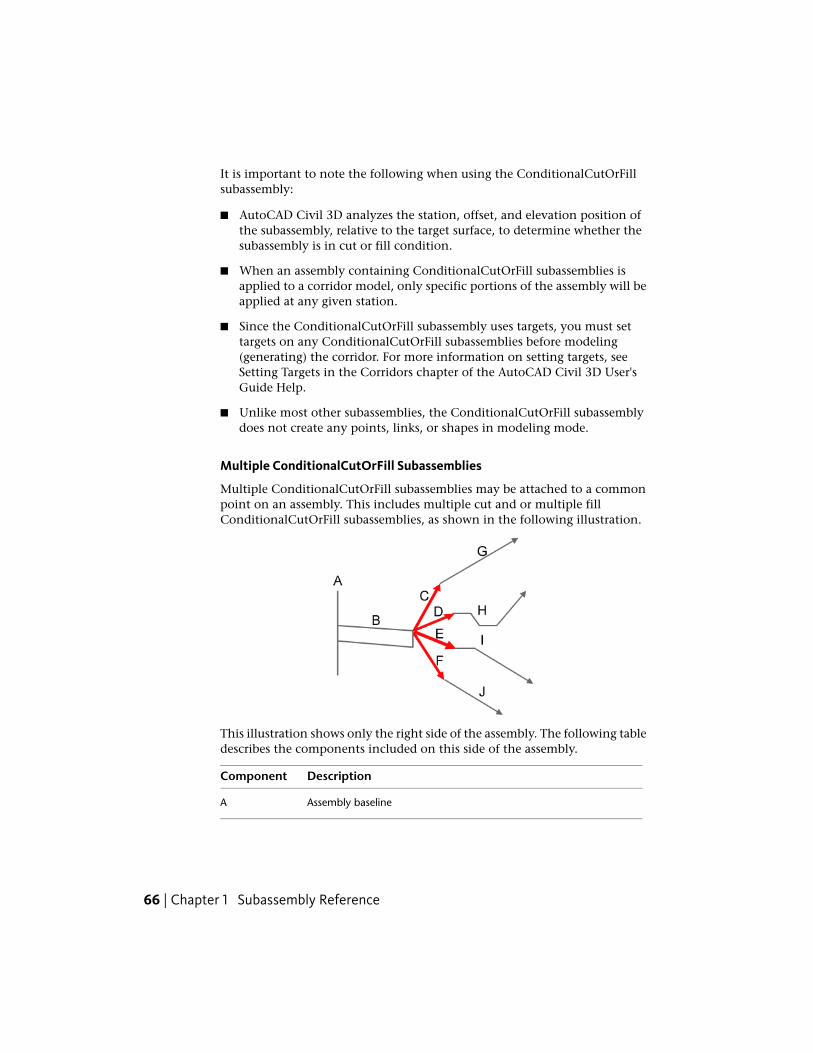
It is important to note the following when using the ConditionalCutOrFillsubassembly:
■ AutoCAD Civil 3D analyzes the station, offset, and elevation position ofthe subassembly, relative to the target surface, to determine whether thesubassembly is in cut or fill condition.
■ When an assembly containing ConditionalCutOrFill subassemblies isapplied to a corridor model, only specific portions of the assembly will beapplied at any given station.
■ Since the ConditionalCutOrFill subassembly uses targets, you must settargets on any ConditionalCutOrFill subassemblies before modeling(generating) the corridor. For more information on setting targets, seeSetting Targets in the Corridors chapter of the AutoCAD Civil 3D User'sGuide Help.
■ Unlike most other subassemblies, the ConditionalCutOrFill subassemblydoes not create any points, links, or shapes in modeling mode.
Multiple ConditionalCutOrFill Subassemblies
Multiple ConditionalCutOrFill subassemblies may be attached to a commonpoint on an assembly. This includes multiple cut and or multiple fillConditionalCutOrFill subassemblies, as shown in the following illustration.
This illustration shows only the right side of the assembly. The following tabledescribes the components included on this side of the assembly.
DescriptionComponent
Assembly baselineA
66 | Chapter 1 Subassembly Reference

DescriptionComponent
Right side Lane subassemblyB
ConditionalCutOrFill subassembly, with Type parameter set to Cut.If the condition is in cut, and the cut condition is between the minim-
C
um/maximum distance values specified for subassembly (C), then aspecified type of subassembly (G) is applied.
ConditionalCutOrFill subassembly, with Type parameter set to Cut.If the condition is in cut, and the cut condition is between the minim-
D
um/maximum distance values specified for subassembly (D), then aDitch subassembly (H) is applied.
ConditionalCutOrFill subassembly, with Type parameter set to Fill. Ifthe condition is in fill, and the fill condition is between the minim-
E
um/maximum distance values specified for subassembly (E), then aspecified type of subassembly (I) is applied.
ConditionalCutOrFill subassembly, with Type parameter set to Fill. Ifthe condition is in fill, and the fill condition is between the minim-
F
um/maximum distance values specified for subassembly (F), then aspecified type of subassembly (J) is applied.
A specified type of subassembly that is applied in cut conditions thatare between the minimum/maximum distance values specified forsubassembly (C).
G
A specified type of subassembly that is applied in cut conditions thatare between the minimum/maximum distance values specified forsubassembly (D).
H
A specified type of subassembly that is applied in fill conditions thatare between the minimum/maximum distance values specified forsubassembly (E).
I
A specified type of subassembly that is applied in fill conditions thatare between the minimum/maximum distance values specified forsubassembly (E).
J
You control the cut or fill limit heights using the Minimum Distance andMaximum Distance input parameters. The Layout Width and Layout Grade
ConditionalCutOrFill | 67
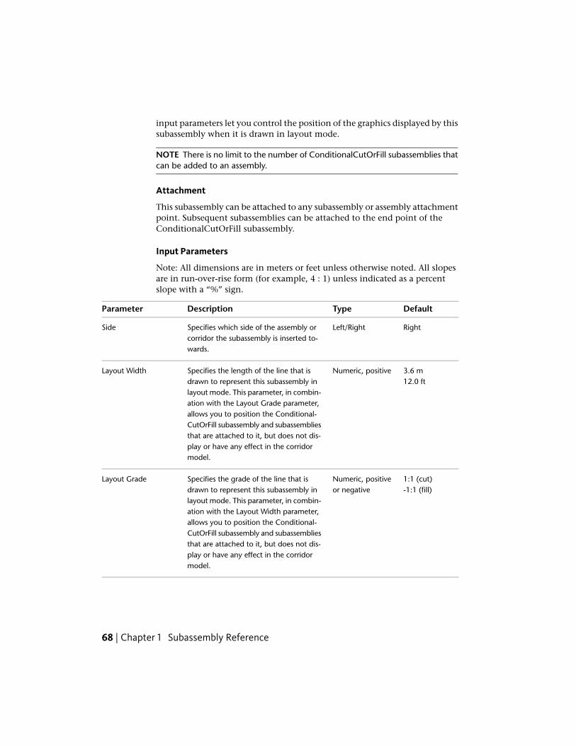
input parameters let you control the position of the graphics displayed by thissubassembly when it is drawn in layout mode.
NOTE There is no limit to the number of ConditionalCutOrFill subassemblies thatcan be added to an assembly.
Attachment
This subassembly can be attached to any subassembly or assembly attachmentpoint. Subsequent subassemblies can be attached to the end point of theConditionalCutOrFill subassembly.
Input Parameters
Note: All dimensions are in meters or feet unless otherwise noted. All slopesare in run-over-rise form (for example, 4 : 1) unless indicated as a percentslope with a “%” sign.
DefaultTypeDescriptionParameter
RightLeft/RightSpecifies which side of the assembly orcorridor the subassembly is inserted to-wards.
Side
3.6 mNumeric, positiveSpecifies the length of the line that isdrawn to represent this subassembly in
Layout Width12.0 ft
layout mode. This parameter, in combin-ation with the Layout Grade parameter,allows you to position the Conditional-CutOrFill subassembly and subassembliesthat are attached to it, but does not dis-play or have any effect in the corridormodel.
1:1 (cut)Numeric, positiveor negative
Specifies the grade of the line that isdrawn to represent this subassembly in
Layout Grade-1:1 (fill)
layout mode. This parameter, in combin-ation with the Layout Width parameter,allows you to position the Conditional-CutOrFill subassembly and subassembliesthat are attached to it, but does not dis-play or have any effect in the corridormodel.
68 | Chapter 1 Subassembly Reference

DefaultTypeDescriptionParameter
CutCut / FillSpecifies the type of condition this sub-assembly uses to compare itself againstthe target.
Type
0.0 mNumeric, positiveor negative
Specifies the minimum cut depth orminimum fill height that is required in
Minimum Distance0.0 ft
order to continue processing subassem-blies connected to this ConditionalCutOr-Fill subassembly.
9999. ftNumeric, positiveSpecifies the maximum cut depth ormaximum fill height that is required in
Maximum Distance9999. m
order to continue processing subassem-blies connected to this ConditionalCutOr-Fill subassembly.
Target ParametersThis section lists the parameters in this subassembly that can be mapped toone or more target objects, such as a surface, alignment, or profile object ina drawing. For more information, see Setting Targets in the AutoCAD Civil3D User’s Guide Help.
StatusDescriptionParameter
RequiredSurface that is used to determine whether thecurrent station, offset, and elevation is in a cut or
Surface
a fill condition. The station, offset, and elevationthat is used is from the ConditionalCutOrFill sub-assembly attachment point.
Output Parameters
None.
Behavior
See description.
ConditionalCutOrFill | 69

Layout Mode Operation
In layout mode, this subassembly draws a line using the Layout Width andLayout Grade input parameter values. This line represents the location in theassembly where the ConditionalCutOrFill subassembly is applied.
Point, Link, and Shape Codes
Unlike most other subassemblies, the ConditionalCutOrFill subassembly doesnot create any points, links, or shapes in modeling mode.
Coding Diagram
The following coding diagram shows the points and links that are created inlayout mode. No point, link, or shape codes are created for this subassemblyin modeling mode.
ConditionalHorizontalTargetThis subassembly automatically applies various subassemblies, such aswidening, curb and gutter, ditching, or daylighting, to an assembly based onwhether an offset target is found at the corridor station.
The ConditionalHorizontalTarget subassembly is a conditional subassembly,which is a special type of subassembly. Conditional subassembliesautomatically add specified subassemblies to an assembly when certainconditions, which you specify, exist.
For example, when an assembly contains a ConditionalHorizontalTargetsubassembly, AutoCAD Civil 3D analyzes the station to determine whetheran offset target exists within a specified distance. Depending on theConditionalHorizontalTarget subassembly parameters, different types ofsubassemblies are automatically added to the assembly.
To learn more about how to use a conditional subassembly, see the Tutorial:Creating an Assembly with Conditions tutorial.
70 | Chapter 1 Subassembly Reference

The following illustration shows a corridor assembly section comprised of:
■ a left side lane and a right side lane
■ four ConditionalHorizontalTarget subassemblies (two on the left side andtwo on the right side)
■ the top left side ConditionalHorizontalTarget subassembly is configuredto automatically add a sidewalk subassembly when an offset target isdetected.
■ the bottom left side ConditionalHorizontalTarget subassembly is configuredto automatically add Shoulder and Gradient subassemblies on the left side,when an offset target is not detected.
■ similarly, the top right side ConditionalHorizontalTarget subassembly isconfigured to add a sidewalk subassembly when an offset target is detected,while the bottom right side ConditionalHorizontalTarget subassemblyadds Shoulder and Gradient subassemblies on the right side, when an offsettarget is not detected.
You can add one or multiple ConditionalHorizontalTarget subassemblies toan assembly to create simple or complex conditional behaviors. For example,in the case of the previous example, you can add a set of polylines to themodel that show the location of sidewalks. Because the lines stop wheredriveways cross the sidewalk, the conditional subassembly adds and removesthe sidewalk depending on the presence of the sidewalk line. The conditionalsubassembly eliminates the need to apply a different assembly to the corridorwhere a sidewalk is not needed.
ConditionalHorizontalTarget | 71
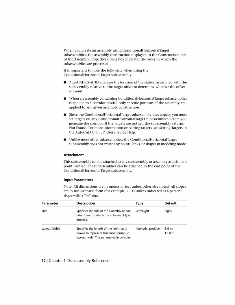
When you create an assembly using ConditionalHorizontalTargetsubassemblies, the assembly construction displayed in the Construction tabof the Assembly Properties dialog box indicates the order in which thesubassemblies are processed.
It is important to note the following when using theConditionalHorizontalTarget subassembly:
■ AutoCAD Civil 3D analyzes the location of the station associated with thesubassembly relative to the target offset to determine whether the offsetis found.
■ When an assembly containing ConditionalHorizontalTarget subassembliesis applied to a corridor model, only specific portions of the assembly areapplied to any given assembly construction.
■ Since the ConditionalHorizontalTarget subassembly uses targets, you mustset targets on any ConditionalHorizontalTarget subassemblies before yougenerate the corridor. If the targets are not set, the subassembly returnsNot Found. For more information on setting targets, see Setting Targets inthe AutoCAD Civil 3D User’s Guide Help.
■ Unlike most other subassemblies, the ConditionalHorizontalTargetsubassembly does not create any points, links, or shapes in modeling mode.
Attachment
This subassembly can be attached to any subassembly or assembly attachmentpoint. Subsequent subassemblies can be attached to the end point of theConditionalHorizontalTarget subassembly.
Input Parameters
Note: All dimensions are in meters or feet unless otherwise noted. All slopesare in run-over-rise form (for example, 4 : 1) unless indicated as a percentslope with a “%” sign.
DefaultTypeDescriptionParameter
RightLeft/RightSpecifies the side of the assembly or cor-ridor towards which this subassembly isinserted.
Side
3.6 mNumeric, positiveSpecifies the length of the line that isdrawn to represent this subassembly in
Layout Width12.0 ft
layout mode. This parameter, in combin-
72 | Chapter 1 Subassembly Reference

DefaultTypeDescriptionParameter
ation with the Layout Grade parameter,enables you to position the Conditional-HorizontalTarget subassembly and sub-assemblies that are attached to it, butdoes not display or have any effect in thecorridor model.
1:1 (found)Numeric, positive,or negative
Specifies the grade of the line that isdrawn to represent this subassembly in
Layout Grade-1:1 (notfound)layout mode. This parameter, in combin-
ation with the Layout Width parameter,enables you to position the Conditional-HorizontalTarget subassembly and sub-assemblies that are attached to it, butdoes not display or have any effect in thecorridor model.
FoundFound/Not FoundSpecifies the condition available for thissubassembly. The Found condition is
Condition
processed if the offset target is foundwithin the maximum distance. The NotFound condition is processed if the offsettarget is not set or is not found at thestation within the maximum distance.
9999. ftNumeric, positiveSpecifies the maximum width withinwhich the subassembly looks for the off-
Maximum Distance9999. m
set target. If the offset is not found withinthe specified distance, the Not Foundconditional is processed.
Target ParametersThis section lists the parameters in this subassembly that can be mapped tooffset target objects in a drawing. For more information, see Setting Targetsin the AutoCAD Civil 3D User’s Guide Help.
StatusDescriptionParameter
Optional (if not set, the con-ditional returns Not Found)
Alignment, feature line, survey figure or polylines.If the specified offset target is found at the station,then the Found condition is processed.
Offset
ConditionalHorizontalTarget | 73

Output Parameters
None.
Behavior
See description.
Layout Mode Operation
In layout mode, this subassembly draws a line using the Layout Width andLayout Grade input parameter values. This line represents the location in theassembly where the ConditionalHorizontalTarget subassembly is applied.
Point, Link, and Shape Codes
Unlike most other subassemblies, the ConditionalHorizontalTarget subassemblydoes not create any points, links, or shapes in modeling mode.
Coding Diagram
The following coding diagram shows the points and links that are created inlayout mode. No point, link, or shape codes are created for this subassemblyin modeling mode.
CrownedLaneThis subassembly creates a crowned lane that has separate subbase slopecontrol, as well as the ability to control the subbase crown location byspecifying a target alignment.
74 | Chapter 1 Subassembly Reference

Attachment
The attachment point is at the beginning of the first link. The subassemblyis sensitive to the direction being inserted. Positive widths increase the offsetfrom the attachment point in the direction inserted.
Input Parameters
Note: All dimensions are in meters or feet unless otherwise noted. All slopesare in run-over-rise form (for example, 4 : 1) unless indicated as a percentslope with a “%” sign.
DefaultTypeDescriptionParameter
3.6 mNumeric, positiveWidth of the left lane from the off-set of the inside edge to the offsetof the outside edge
Left Lane Width12.0 ft
3.6 mNumeric, positiveWidth of the right lane from theoffset of the inside edge to the off-set of the outside edge
Right Lane Width12.0 ft
-2.0NumericDefault % Left Slope of the lane tobe used when the superelevation
Default % Left Slope
slope of the alignment is notdefined
-2.0NumericDefault % Right Slope of the laneto be used when the superelevation
Default % Right Slope
slope of the alignment is notdefined
-3.0NumericSpecifies the slope of the base andsubbase materials. In superelevation
Base % Slope
CrownedLane | 75

DefaultTypeDescriptionParameter
will be calculated as the differencebetween Default slope and baseslope, then added to Supereleva-tion value.
0.025 mNumeric, positiveThickness of the Pave1 layer (zeroto omit)
Pave1 Depth0.083 ft
0.025 mNumeric, positiveThickness of the Pave2 layer (zeroto omit)
Pave2 Depth0.083 ft
0.100 mNumeric, positiveThickness of the Base layer at crownBase Depth0.333 ft
0.300 mNumeric, positiveThickness of the Subbase layerSubbase Depth1.0 ft
Target ParametersThis section lists the parameters in this subassembly that can be mapped toone or more target objects, such as a surface, alignment, or profile object ina drawing. For more information, see Setting Targets in the AutoCAD Civil3D User’s Guide Help.
StatusDescriptionParameter
OptionalMay be used to override the fixed left laneWidth and tie the edge-of-lane to an offset
Left Width
alignment. The following object types can beused as targets for specifying this width:alignments, polylines, features lines, or surveyfigures.
OptionalMay be used to override the normal lane slopeand tie the outer edge of the left travel lane
Left Outside Elevation
to the elevation of a profile. The followingobject types can be used as targets for specify-ing this: profiles, 3D polylines, feature lines,or survey figures.
OptionalMay be used to override the fixed right laneWidth and tie the edge-of-lane to an offset
Right Width
76 | Chapter 1 Subassembly Reference

StatusDescriptionParameter
alignment. The following object types can beused as targets for specifying this width:alignments, polylines, features lines, or surveyfigures.
OptionalMay be used to override the normal lane slopeand tie the outer edge of the right travel lane
Right Outside Elevation
to the elevation of a profile. The followingobject types can be used as targets for specify-ing this: profiles, 3D polylines, feature lines,or survey figures.
OptionalMay be used to override the crown locationof the base and subbase materials. The follow-
Base Centerline
ing object types can be used as targets forspecifying this: alignments, polylines, featureslines, or survey figures.
Output Parameters
TypeDescriptionParameter
Numeric% slope of the Left LaneLeft Lane %Slope
Numeric% Slope of Right LaneRight Lane % Slope
Behavior
The Inside Lane superelevation slope is obtained from the superelevationspecifications for the baseline alignment. Starting at the attachment point, afinish grade surface and parallel subgrade are inserted using the given width,depth, and the superelevation slope. Vertical links close the shape at eitherend of the lane.
If an offset horizontal alignment name is assigned to the Left or Right widthduring corridor modeling, the width of the lane will vary to match the offsetof the alignment.
If an alignment is specified for base centerline then the crown point of thebase and subbase layers will shift to the location of this alignment.
CrownedLane | 77

Layout Mode Operation
In layout mode, this subassembly displays the links defined by the inputparameters.
Point, Link, and Shape CodesThe following table lists the point, link, and shape codes for this subassemblythat have codes assigned to them. Point, link, or shape codes for thissubassembly that do not have codes assigned are not included in this table.
DescriptionCodesPoint, Link, or Shape
Edge-of-traveled-way on finish gradeETWP1/P3
Crown point on finish gradeCrownP2
Outside edge of lane on finish gradeLaneP1/P3
Edge-of-traveled-way on the Pave1 layerETW_Pave1P4/P6
Crown point on the Pave1 layerCrown_Pave1P5
Outside edge of lane on the Pave1 layerLane_Pave1P4/P6
Edge-of-traveled-way on the Pave2 layerETW_Pave2P7/P9
Crown point on the Pave2 layerCrown_Pave2P8
Outside edge of lane on the Pave2 layerLane_Pave2P7/P9
Edge-of-traveled-way edge of lane on the Base layerETW_BaseP11/P13
Crown point on base layer (optional)Crown_BaseP12
Outside edge of lane on the Base layerLane_BaseP11/P13
Edge-of-traveled-way edge of lane on the subbaselayer
ETW _SubP14/P16
Crown point on subbase layer (optional)Crown_SubP15
Outside edge of lane on the Subbase layerLane_SubP14/P16
Finish grade surfaceTop, PaveL1 ,L2
78 | Chapter 1 Subassembly Reference

DescriptionCodesPoint, Link, or Shape
Pave1L3,L4
Pave2L5,L6
Base surfaceBaseL7,L8
Subbase surfaceSubBaseL9,L10Datum
Pave1S1
Pave2S2
BaseS3
SubbaseS4
Coding Diagram
DaylightBasinThis subassembly inserts links to create a basin and cut daylight slope for acut condition, or a basin, berm, and fill slope for a fill condition.
The final daylighting link can be omitted in cases where the corridor modelneeds to be left in an incomplete state. For example, this might be done sothat grading surfaces on adjacent properties can tie to the hinge point on theuncompleted roadway.
DaylightBasin | 79

You can also specify optional lined materials for daylight and other links (AllLinks, Daylight Links, Fill Links Only, and None).
Attachment
The attachment point is at the inside edge of the basin foreslope. Thiscomponent can be attached to either the left or right side.
Input ParametersNote: All dimensions are in meters or feet unless otherwise noted. All slopesare in run-over-rise form (for example, 4 : 1) unless indicated as a percentslope with a “%” sign.
DefaultTypeDescriptionParameter
RightLeft / RightSpecifies which side to place thesubassembly
Side
IncludeInclude / OmitIncludes or omits the Daylight link.Daylight Link
3 ( : 1)Numeric, positiveThe slope for the basin foreslope linkForeSlope Slope
1.2 mNumeric, positiveThe width of the foreslopeForeSlope Width
80 | Chapter 1 Subassembly Reference

DefaultTypeDescriptionParameter
4.0 ft
0.0Numeric, positiveThe depth of the bottom of thebasin from the bottom of theforeslope link
Basin Depth
4 ( : 1)Numeric, positiveThe slope of the sides of the basinBasin Slope
1.8 mNumeric, positiveWidth of the basinBasin Width6.0 ft
1.8 mNumeric, positiveWidth of the berm used in fill condi-tions
Berm Width6.0 ft
3 ( : 1)Numeric, positiveThe slope of the daylight link in cutconditions
Cut Slope
3 ( : 1)Numeric, positiveThe slope of the daylight link in fillconditions
Fill Slope
NoneStringSpecifies to round off the daylightlink at the catch point
Rounding Option
LengthStringSpecifies what parameter is used forrounding
Rounding By
1.500 ftNumeric, positiveSpecifies value for length or radiusRounding Parameter
6Numeric, positiveSpecifies number of intermittentpoints on rounding links (maximum10 links)
Rounding Tesselation
NoneStringSpecifies to place optional materiallining along daylight links. You can
Place Lined Material
choose All Links, Daylight Links, FillLinks Only, and None.
1 : 1SlopeSpecifies the slope limit until whichthe associated material lining isplaced
Slope Limit 1
DaylightBasin | 81

DefaultTypeDescriptionParameter
12 inchesNumeric, positiveSpecifies the thickness of lined ma-terial. This thickness is measuredperpendicular to the link.
Material 1 Thickness
Rip RapStringSpecifies the name of the materialapplies for lining along grading links
Material 1 Name
2 : 1SlopeSpecifies the slope limit until whichthe associated material lining isplaced
Slope Limit 2
6 inchesNumeric, positiveSpecifies the thickness of lined ma-terial. This thickness is measuredperpendicular to the link.
Material 2 Thickness
Rip RapStringSpecifies the name of the materialapplies for lining along grading links
Material 2 Name
4 : 1SlopeSpecifies the slope limit until whichthe associated material lining isplaced
Slope Limit 3
4 inchesNumeric, positiveSpecifies the thickness of lined ma-terial. This thickness is measuredperpendicular to the link.
Material 3 Thickness
SeededGrass
StringSpecifies the name of the materialapplies for lining along grading links
Material 3 Name
Target ParametersThis section lists the parameters in this subassembly that can be mapped toone or more target objects. For more information, see Setting Targets in theAutoCAD Civil 3D User’s Guide Help.
StatusDescriptionParameter
OptionalMay be used to override the fixed Basin Depth and tie theelevation of the basin to a profile (or other object type).
Basin Elevation
The following object types can be used as targets for spe-cifying the elevation: profiles, 3D polylines, feature lines,or survey figures.
82 | Chapter 1 Subassembly Reference

StatusDescriptionParameter
RequiredName of the daylighting surface. The following objecttypes can be used as targets for specifying the surface:surfaces.
Daylight Surface
Output Parameters
None.
Behavior
The subassembly builds the links for the basin foreslope and basin out to thebasin test point. If a profile is given, the width of the foreslope varies to holdto the basin profile, while the basin depth is held constant. If the basin testpoint is in cut, the daylight intercept is calculated on the target surface at thegiven Cut Slope. If it is in fill, a top-of-berm link is added, and the daylightintercept is calculated on the target surface at the given Fill Slope. The daylightlink is not inserted if Omit Daylight Link is set to True. If the top-of-berm linkintersects the target surface, the section is terminated at the intersection.
Like other daylight subassemblies, this subassembly optionally lets you adda lined material. You can specify three ranges of slopes. Material type 1 isapplied if the slope of the links is up to the specified slope value. From slope1 to slope 2, the second type of material applied. Similarly, if the slopes oflinks fall within slope 2 and slope 3 values, then material 3 is applied. If thelink slopes are flatter than slope limit 3, then no material is applied.
If a lined material is added to the subassembly, then parallel links are addedto the daylight links with specified thickness. This thickness parameter (forexample, Material 1 Thickness) is measured perpendicular to the link. Bottomlevel links are coded with Datum and daylight links are coded with Top. Shapesenclosed by these materials are coded with material name.
NOTE In Civil 3D 2010 and previous versions, the Material Thickness parameterwas measured vertically. In Civil 3D 2011 and later, this parameter is measuredperpendicular to the link. Therefore, if you open a drawing containing thesesubassemblies that was created in Civil 3D 2010 or prior in Civil 3D 2011 or later,and then rebuild the corridor(s), this parameter will be changed to reflect the newbehavior. Any volume reports that use this subassembly will be updated to reflectthe new behavior.
DaylightBasin | 83

Layout Mode Operation
In layout mode, this subassembly draws the foreslope, basin sideslopes, andbasin bottom with the given input parameter values. Both the cut and fillcondition links are shown in dashed lines, with the daylight links extendedoutward for a width of 3 meters or 10 feet at the given slopes. The daylightlinks terminate in arrowheads pointing outwards.
Point, Link, and Shape CodesThe following table lists the point, link, and shape codes for this subassemblythat have codes assigned to them. Point, link, or shape codes for thissubassembly that do not have codes assigned are not included in this table.
DescriptionCodePoint, Link, or Shape
Inside bottom of basinDitch_InP3
Outside bottom of basinDitch_OutP4
Hinge point for the cut conditionHingeP5Hinge_Cut
Hinge point for the fill conditionHingeP6Hinge_Fill
Daylight point, and daylight point foreither the cut or fill condition
DaylightDaylight_Cut or
P7
Daylight_Fill
TopAll linksDatum
Daylight link for cut sectionTopL6DatumDaylightDaylight_Cut
Daylight link for fill sectionTopL6DatumDaylightDaylight_Fill
84 | Chapter 1 Subassembly Reference

Coding Diagram
DaylightBasin2This subassembly is similar to the DaylightBasin subassembly with thefollowing additional behaviors:
The berm is optional in fill conditions. If no berm is included, a clear zoneslope is added, and then a daylight fill slope is added.
The Ditch Width can be controlled by using an optional alignment. BermWidth and Height can be controlled by using an alignment and a profilerespectively. In addition, the Place Lined Material needs to include all linksof the daylight assemblies from the hinge point out to the daylight to existingground.
DaylightBasin2 | 85
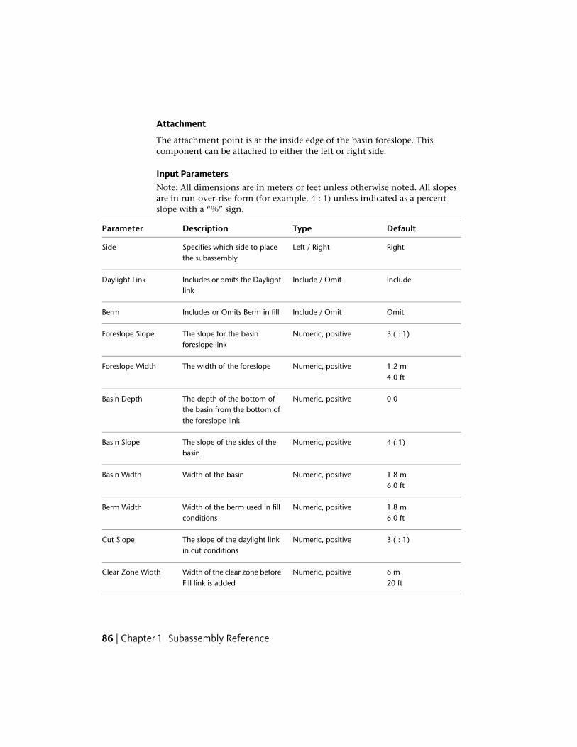
Attachment
The attachment point is at the inside edge of the basin foreslope. Thiscomponent can be attached to either the left or right side.
Input ParametersNote: All dimensions are in meters or feet unless otherwise noted. All slopesare in run-over-rise form (for example, 4 : 1) unless indicated as a percentslope with a “%” sign.
DefaultTypeDescriptionParameter
RightLeft / RightSpecifies which side to placethe subassembly
Side
IncludeInclude / OmitIncludes or omits the Daylightlink
Daylight Link
OmitInclude / OmitIncludes or Omits Berm in fillBerm
3 ( : 1)Numeric, positiveThe slope for the basinforeslope link
Foreslope Slope
1.2 mNumeric, positiveThe width of the foreslopeForeslope Width4.0 ft
0.0Numeric, positiveThe depth of the bottom ofthe basin from the bottom ofthe foreslope link
Basin Depth
4 (:1)Numeric, positiveThe slope of the sides of thebasin
Basin Slope
1.8 mNumeric, positiveWidth of the basinBasin Width6.0 ft
1.8 mNumeric, positiveWidth of the berm used in fillconditions
Berm Width6.0 ft
3 ( : 1)Numeric, positiveThe slope of the daylight linkin cut conditions
Cut Slope
6 mNumeric, positiveWidth of the clear zone beforeFill link is added
Clear Zone Width20 ft
86 | Chapter 1 Subassembly Reference

DefaultTypeDescriptionParameter
6 (:1)Numeric, positiveSlope for the clear zoneClear Zone Slope
3 ( : 1)Numeric, positiveSlope of the daylight link in fillconditions
Fill Slope
NoneList of options: None,Circular, Parabolic
Specifies whether to round offthe daylight link at the catchpoint
Rounding Option
LengthList of options: Length,Radius
Specifies the parameter that isused for rounding
Rounding By
0.5 mNumeric, positiveSpecifies value for length ofradius
Rounding Parameter1.5 ft
6Numeric, positive integerSpecifies number of intermit-tent points on rounding links(Max 10 links)
Rounding Tessella-tion
NoneStringSpecifies to place optionalmaterial lining along daylight
Place Lined Material
links. You can choose All Links,Daylight Links, Fill Links Only,and None.
1 : 1SlopeSpecifies the slope limit untilwhich the associated materiallining is placed
Slope Limit 1
12 inchesNumeric, positiveSpecifies the thickness of linedmaterial. This thickness is
Material 1 Thickness
measured perpendicular to thelink.
Rip RapStringSpecifies the name of the ma-terial applies for lining alonggrading links
Material 1 Name
2 : 1SlopeSpecifies the slope limit untilwhich the associated materiallining is placed
Slope Limit 2
DaylightBasin2 | 87

DefaultTypeDescriptionParameter
6 inchesNumeric, positiveSpecifies the thickness of thelined material. This thickness
Material 2 Thickness
is measured perpendicular tothe link.
Rip RapStringSpecifies the name of the ma-terial applied for lining alonggrading links
Material 2 Name
4 : 1SlopeSpecifies the slope limit untilwhich the associated materiallining is placed
Slope Limit 3
4 inchesNumeric, positiveSpecifies the thickness of thelined material. This thickness
Material 3 Thickness
is measured perpendicular tothe link.
Seeded GrassStringSpecifies the name of the ma-terial applied for lining alonggrading links
Material 3 Name
6 inchesNumeric, positiveSpecifies thickness of the ma-terial to be applied in flat slopesituations
Material 4 Thickness
GravelStringSpecifies the material name tobe used in flat slope situations
Material 4 Name
Target ParametersThis section lists the parameters in this subassembly that can be mapped toone or more target objects, such as a surface, alignment, or profile object ina drawing. For more information, see Setting Targets in the AutoCAD Civil3D User’s Guide Help.
StatusDescriptionParameter
OptionalMay be used to override the fixed Basin Width Thefollowing object types can be used as targets for spe-
Basin WidthAlignment
cifying this: alignments, polylines, feature lines, orsurvey figures.
88 | Chapter 1 Subassembly Reference

StatusDescriptionParameter
OptionalMay be used to override the fixed Berm Width. Thefollowing object types can be used as targets for spe-
Berm WidthAlignment
cifying this: alignments, polylines, feature lines, orsurvey figures.
OptionalMay be used to override the fixed Basin Depth and tiethe elevation of the basin to a profile. The following
Basin Elevation
object types can be used as targets for specifying thiselevation: profiles, 3D polylines, feature lines, or surveyfigures.
OptionalAllows the height of the berm to be overridden. Thefollowing object types can be used as targets for spe-
Berm HeightProfile
cifying this height: profiles, 3D polylines, feature lines,or survey figures.
RequiredName of the daylighting surface. The following objecttypes can be used as targets for specifying this surface:surfaces.
Daylight Surface
Output Parameters
None.
Behavior
This subassembly builds the links for the basin foreslope and the basin out tothe basin test point. If a profile is given, the width of the foreslope varies tohold to the basin profile. If the basin test point is in cut, the daylight interceptis calculated on the target surface at the given cut slope.
If it is in fill, and Berm is set to Include, a top-of-berm link is added, and thedaylight intercept is calculated on the target surface at the given Fill Slope.The daylight link is not inserted if Omit Daylight Link is set to True. If thetop-of-berm link intersects the target surface, the section is terminated at theintersection.
If it is in fill, and Berm is set to Omit, a link is added from the attachmentpoint at the Clear Zone Slope until the Clear Zone Width is met. Then adaylight link is added to the target surface at the fill slope specified. If theclear zone link intersects existing ground, it will stop at this intersection point.
DaylightBasin2 | 89

Like other daylight subassemblies, this subassembly optionally lets you adda lined material. You can specify three ranges of slopes. Material type 1 isapplied if the slope of the links is up to the specified slope value. From slope1 to slope 2, the second type of material is applied. Similarly, if the slopes oflinks fall within slope 2 and slope 3 values, then material 3 is applied. If thelink slopes are flatter than slope limit 3, then no material is applied.
If a lined material is added to the subassembly, then parallel links are addedto the daylight links with specified thickness. This thickness parameter (forexample, Material 1 Thickness) is measured perpendicular to the link. Bottomlevel links are coded with Datum, and daylight links are coded with Top.Shapes enclosed by these materials are coded with material name (Material 1Name, Material 2 Name, or Material 3 Name).
NOTE In Civil 3D 2010 and previous versions, the Material Thickness parameterwas measured vertically. In Civil 3D 2011 and later, this parameter is measuredperpendicular to the link. Therefore, if you open a drawing containing thesesubassemblies that was created in Civil 3D 2010 or prior in Civil 3D 2011 or later,and then rebuild the corridor(s), this parameter will be changed to reflect the newbehavior. Any volume reports that use this subassembly will be updated to reflectthe new behavior.
Layout Mode Operation
In layout mode, this subassembly draws the foreslope, basin side slopes, andbasin bottom with the given input parameter values. Both the cut and fillcondition links are shown in dashed lines, with the daylight links extendedoutward, for a width of 3 meters (or 10 feet) at the given slopes. The daylightlinks terminate in arrowheads pointing outwards.
90 | Chapter 1 Subassembly Reference
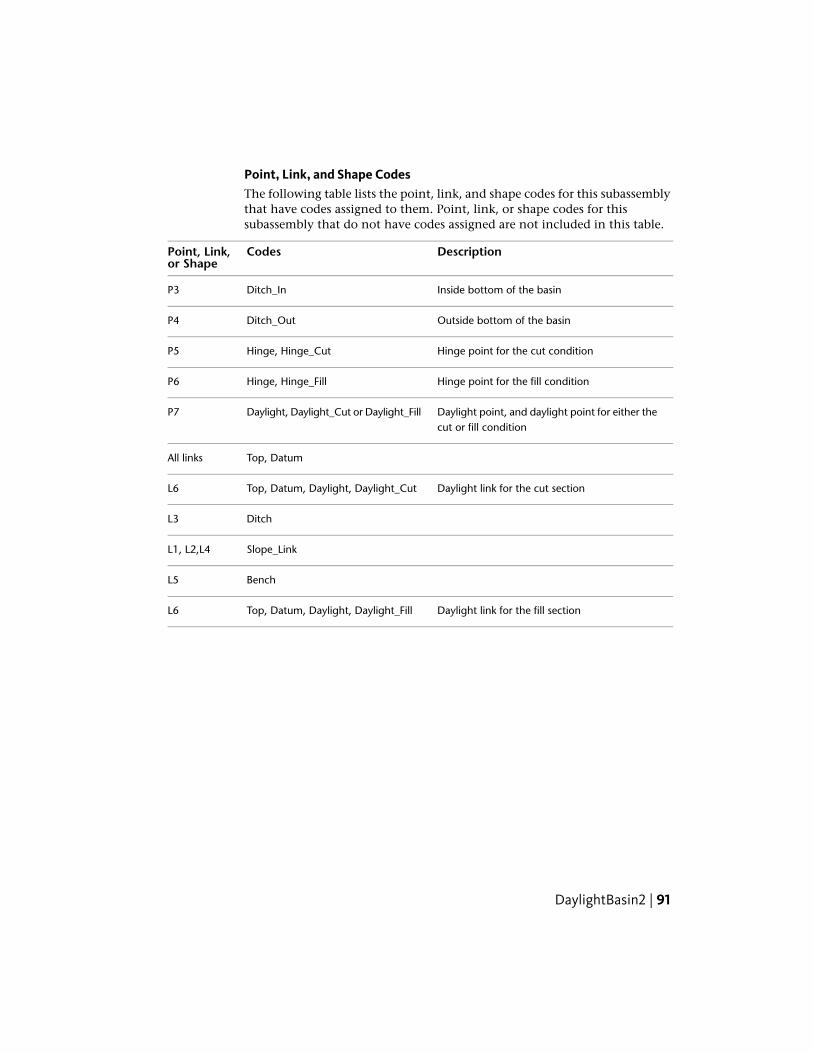
Point, Link, and Shape CodesThe following table lists the point, link, and shape codes for this subassemblythat have codes assigned to them. Point, link, or shape codes for thissubassembly that do not have codes assigned are not included in this table.
DescriptionCodesPoint, Link,or Shape
Inside bottom of the basinDitch_InP3
Outside bottom of the basinDitch_OutP4
Hinge point for the cut conditionHinge, Hinge_CutP5
Hinge point for the fill conditionHinge, Hinge_FillP6
Daylight point, and daylight point for either thecut or fill condition
Daylight, Daylight_Cut or Daylight_FillP7
Top, DatumAll links
Daylight link for the cut sectionTop, Datum, Daylight, Daylight_CutL6
DitchL3
Slope_LinkL1, L2,L4
BenchL5
Daylight link for the fill sectionTop, Datum, Daylight, Daylight_FillL6
DaylightBasin2 | 91

Coding Diagram
DaylightBenchThis subassembly inserts links to create cut or fill catch slopes with repeatingbenches as needed.
You can also specify optional lined materials for daylight and other links (AllLinks, Daylight Links, Fill Links Only, and None).
92 | Chapter 1 Subassembly Reference

Attachment
The attachment point is at the inside edge of the initial cut or fill slope. Thiscomponent can be attached to either the left or right side.
DaylightBench | 93

Input ParametersNote: All dimensions are in meters or feet unless otherwise noted. All slopesare in run-over-rise form (for example, 4 : 1) unless indicated as a percentslope with a “%” sign.
DefaultTypeDescriptionParameter
RightLeft / RightSpecifies which side to place thesubassembly
Side
2 ( : 1)Numeric, positiveThe slope for the cut daylight slopeCut Slope
3.0 mNumericThe maximum allowable height forthe cut daylight link without bench-ing
Max Cut Height10.0 ft
2 ( : 1)Numeric, positiveThe slope for the fill daylight slopeFill slope
3.0 mNumeric, positiveThe maximum allowable height forthe fill daylight link without benching
Max Fill Height10.0 ft
1.5 mNumeric, positiveThe width of the benchBench Width5.0 ft
2 (%)NumericThe +/- % slope of the bench. Positiveslopes are upward in the direction ofincreasing offset
Bench % Slope
NoneStringSpecifies to round off the daylight linkat the catch point
Rounding Option
LengthStringSpecifies what parameter is used forrounding
Rounding By
1.500 ftNumeric, positiveSpecifies value for length or radiusRounding Parameter
6Numeric, positiveSpecifies number of intermittentpoints on rounding links (maximum10 links)
Rounding Tesselation
NoneStringSpecifies to place optional materiallining along daylight links. You can
Place Lined Material
94 | Chapter 1 Subassembly Reference

DefaultTypeDescriptionParameter
choose All Links, Daylight Links, FillLinks Only, and None.
1 : 1SlopeSpecifies the slope limit until whichthe associated material lining isplaced
Slope Limit 1
12 inchesNumeric, positiveSpecifies the thickness of lined mater-ial. This thickness is measured perpen-dicular to the link.
Material 1 Thickness
Rip RapStringSpecifies the name of the materialapplies for lining along grading links
Material 1 Name
2 : 1SlopeSpecifies the slope limit until whichthe associated material lining isplaced
Slope Limit 2
6 inchesNumeric, positiveSpecifies the thickness of lined mater-ial. This thickness is measured perpen-dicular to the link.
Material 2 Thickness
Rip RapStringSpecifies the name of the materialapplies for lining along grading links
Material 2 Name
4 : 1SlopeSpecifies the slope limit until whichthe associated material lining isplaced
Slope Limit 3
4 inchesNumeric, positiveSpecifies the thickness of lined mater-ial. This thickness is measured perpen-dicular to the link.
Material 3 Thickness
SeededGrass
StringSpecifies the name of the materialapplies for lining along grading links
Material 3 Name
DaylightBench | 95

Target ParametersThis section lists the parameters in this subassembly that can be mapped toone or more target objects. For more information, see Setting Targets in theAutoCAD Civil 3D User’s Guide Help.
StatusDescriptionParameter
RequiredName of the daylighting surface. The following objecttypes can be used as targets for specifying the surface:surfaces.
Daylight Surface
Output Parameters
TypeDescriptionParameter
NumericOffset of the daylight pointDaylight Offset
NumericElevation of the daylight pointDaylight Elevation
Behavior
The initial hinge point is set at the attachment point. The hinge point elevationis checked against the target surface to determine if the section is in the cutor fill condition. An intercept is calculated to the target surface using the givenCut Slope or Fill Slope. If the height to the intercept exceeds the Max Height,the link with the Max Height is inserted, and the bench link is added. Thehinge point is reset to the outside edge of the bench and the process is repeateduntil a daylight link is found that does not exceed the Max Height.
Like other daylight subassemblies, this subassembly optionally lets you adda lined material. You can specify three ranges of slopes. Material type 1 isapplied if the slope of the links is up to the specified slope value. From slope1 to slope 2, the second type of material applied. Similarly, if the slopes oflinks fall within slope 2 and slope 3 values, then material 3 is applied. If thelink slopes are flatter than slope limit 3, then no material is applied.
If a lined material is added to the subassembly, then parallel links are addedto the daylight links with specified thickness. This thickness parameter (forexample, Material 1 Thickness) is measured perpendicular to the link. Bottomlevel links are coded with Datum and daylight links are coded with Top. Shapesenclosed by these materials are coded with material name.
96 | Chapter 1 Subassembly Reference

NOTE In Civil 3D 2010 and previous versions, the Material Thickness parameterwas measured vertically. In Civil 3D 2011 and later, this parameter is measuredperpendicular to the link. Therefore, if you open a drawing containing thesesubassemblies that was created in Civil 3D 2010 or prior in Civil 3D 2011 or later,and then rebuild the corridor(s), this parameter will be changed to reflect the newbehavior. Any volume reports that use this subassembly will be updated to reflectthe new behavior.
Layout Mode Operation
In layout mode, this subassembly draws the initial cut and fill slopes to theirmaximum heights, a single bench, followed by cut and fill daylight slopes forhalf the maximum heights. The daylight links terminate with an arrowheadpointing outwards.
Point, Link, and Shape CodesThe following table lists the point, link, and shape codes for this subassemblythat have codes assigned to them. Point, link, or shape codes for thissubassembly that do not have codes assigned are not included in this table.
DescriptionCodePoint, Link, or Shape
Hinge point, either for the cut or fill condition. Thisonly applies to the inside edge of the actual day-lighting link.
HingeHinge_Cut orHinge_Fill
P1
DaylightBench | 97

DescriptionCodePoint, Link, or Shape
Daylight point, and daylight point for either thecut or fill condition. This only applies to the actualdaylight point.
DaylightDaylight_Cut orDaylight_Fill
P2
The inside edge of the bench(es)Bench_InP2
The outside edge of the bench(es)Bench_OutP3
TopAll linksDatum
Daylight link for cut sectionTopFinal daylight linkDatumDaylightDaylight_Cut
Daylight link for fill sectionTopFinal daylight linkDatumDaylightDaylight_Fill
98 | Chapter 1 Subassembly Reference

Coding Diagram
DaylightGeneralThis subassembly is a generalized solution to closing the sections from theoutside edge of roadway to cut or fill intercept point.
It provides a variety of solutions for cut and fill conditions, as described below.Based on the input parameters provided, it first attempts to build a cut section.If unable to do this it builds a fill section instead. The final daylighting linkcan be omitted for cases where the corridor model needs to be left in anincomplete state. For example, this might be done so that grading surfaces onadjacent properties can tie to the hinge point on the uncompleted roadway.
DaylightGeneral | 99
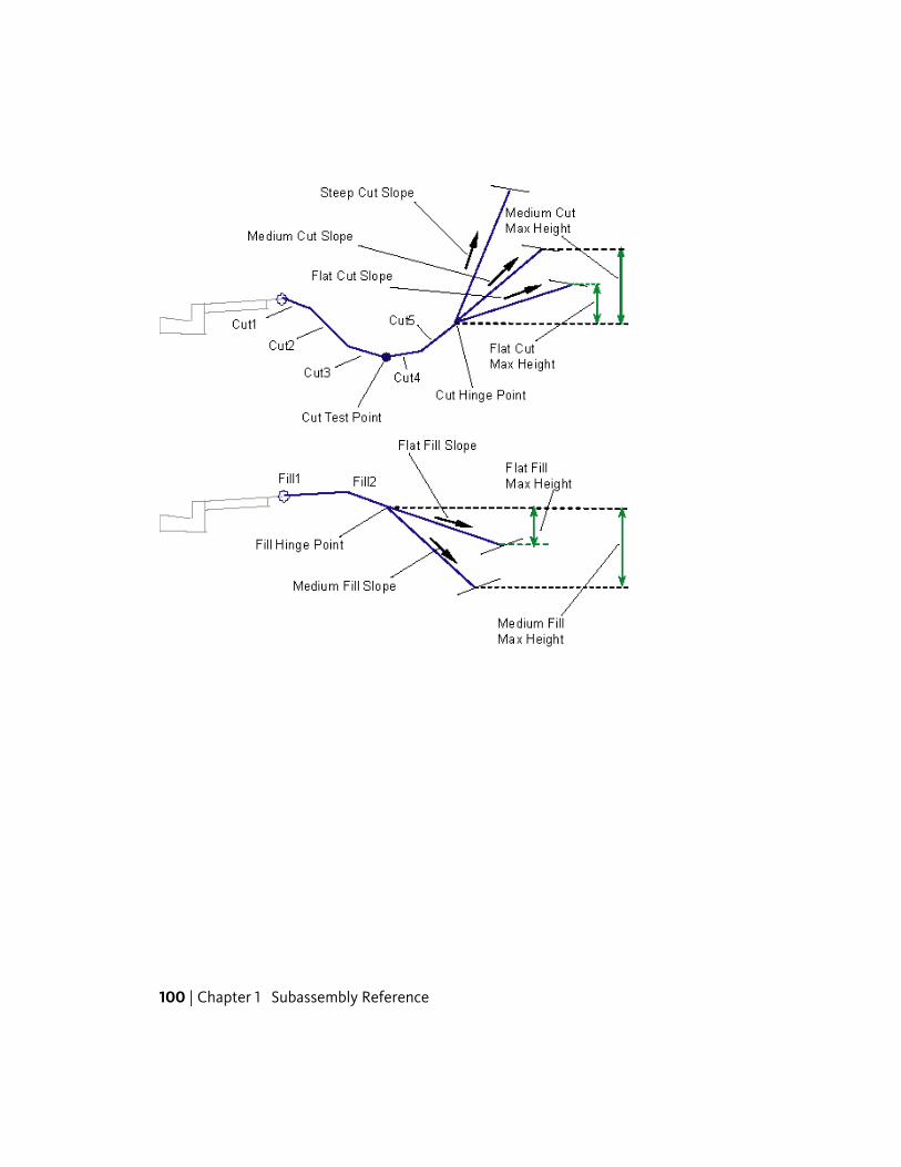
100 | Chapter 1 Subassembly Reference
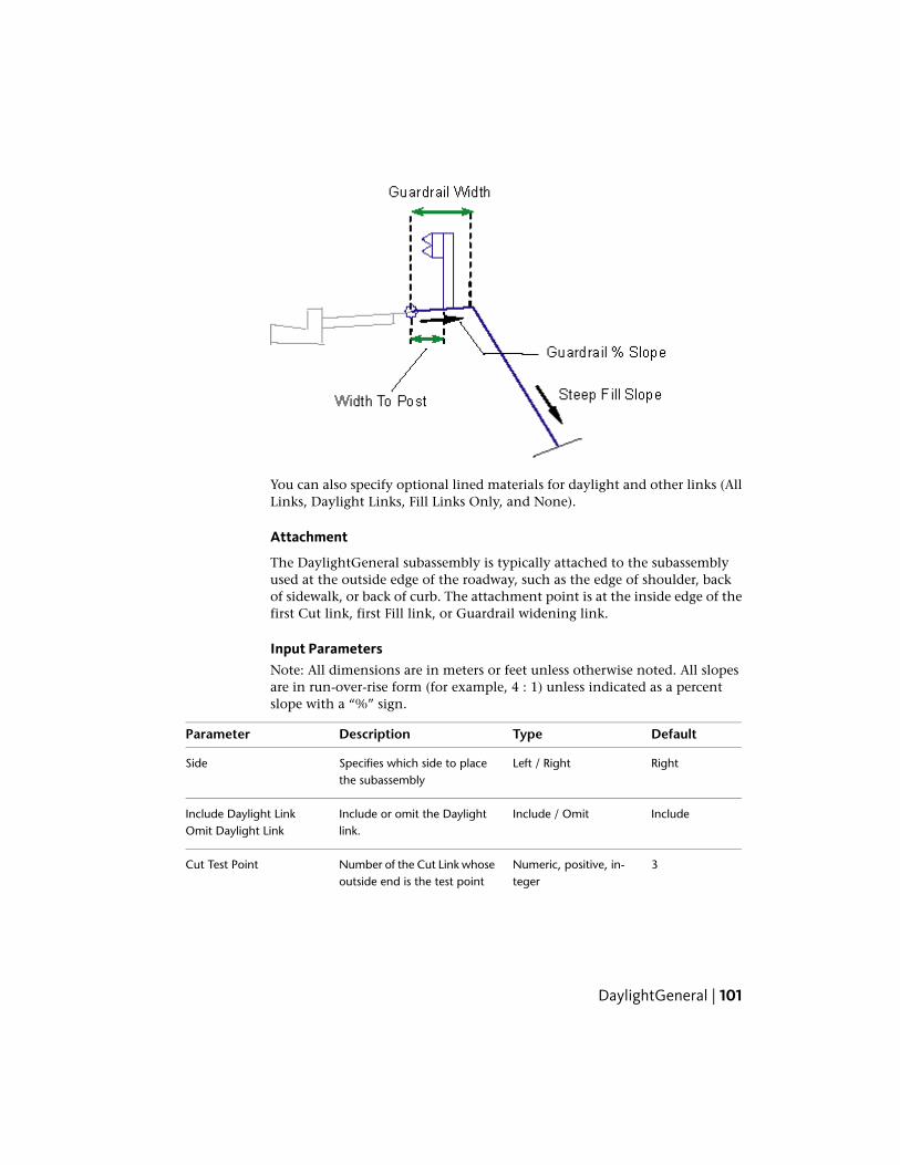
You can also specify optional lined materials for daylight and other links (AllLinks, Daylight Links, Fill Links Only, and None).
Attachment
The DaylightGeneral subassembly is typically attached to the subassemblyused at the outside edge of the roadway, such as the edge of shoulder, backof sidewalk, or back of curb. The attachment point is at the inside edge of thefirst Cut link, first Fill link, or Guardrail widening link.
Input ParametersNote: All dimensions are in meters or feet unless otherwise noted. All slopesare in run-over-rise form (for example, 4 : 1) unless indicated as a percentslope with a “%” sign.
DefaultTypeDescriptionParameter
RightLeft / RightSpecifies which side to placethe subassembly
Side
IncludeInclude / OmitInclude or omit the Daylightlink.
Include Daylight LinkOmit Daylight Link
3Numeric, positive, in-teger
Number of the Cut Link whoseoutside end is the test point
Cut Test Point
DaylightGeneral | 101

DefaultTypeDescriptionParameter
for determining if the sectionis in cut or fill
0.0Numeric, positiveWidth of link Cut 1Cut 1 Width
0.0NumericSlope (x : 1) of link Cut 1Cut 1 Slope
0.0Numeric, positiveWidth of link Cut 2Cut 2 Width
0.0NumericSlope (x : 1) of link Cut 2Cut 2 Slope
0.0Numeric, positiveWidth of link Cut 3Cut 3 Width
0.0NumericSlope (x : 1) of link Cut 3Cut 3 Slope
0.0Numeric, positiveWidth of link Cut 4Cut 4 Width
0.0NumericSlope (x : 1) of link Cut 4Cut 4 Slope
0.0Numeric, positiveWidth of link Cut 5Cut 5 Width
0.0NumericSlope (x : 1) of link Cut 5Cut 5 Slope
0.0Numeric, positiveWidth of link Cut 6Cut 6 Width
0.0NumericSlope (x : 1) of link Cut 6Cut 6 Slope
0.0Numeric, positiveWidth of link Cut 7Cut 7 Width
0.0NumericSlope (x : 1) of link Cut 7Cut 7 Slope
0.0Numeric, positiveWidth of link Cut 8Cut 8 Width
0.0NumericSlope (x : 1) of link Cut 8Cut 8 Slope
6 ( : 1)Numeric, positiveFirst, flattest, catch slope toattempt.
Flat Cut Slope
1.5 mNumeric, positiveMaximum allowable height ofthe closing link using the FlatCut Slope
Flat Cut Max Height5 ft
102 | Chapter 1 Subassembly Reference

DefaultTypeDescriptionParameter
4 ( : 1)Numeric, positiveCut slope to attempt if the FlatCut Slope link exceeds the FlatCut Max Height
Medium Cut Slope
3 mNumeric, positiveMaximum allowable height ofthe closing link using the Medi-um Cut Slope.
Medium Cut Max Height10 ft
2 ( : 1)Numeric, positiveCut slope to use if the MediumCut Slope link exceeds theMedium Cut Max Height.
Steep Cut Slope
0.0Numeric, positiveWidth of link Fill 1Fill 1 Width
0.0NumericSlope (x : 1) of link Fill 1Fill 1 Slope
0.0Numeric, positiveWidth of link Fill 2Fill 2 Width
0.0NumericSlope (x : 1) of link Fill 2Fill 2 Slope
0.0Numeric, positiveWidth of link Fill 3Fill 3 Width
0.0NumericSlope (x : 1) of link Fill 3Fill 3 Slope
6 ( : 1)Numeric, positiveFirst, flattest, catch slope toattempt. (x : 1)
Flat Fill Slope
1.5 mNumeric, positiveMaximum allowable height ofthe closing link using the FlatFill Slope
Flat Fill Max Height5 ft
4 ( : 1)Numeric, positiveFill slope to attempt if the FlatFill Slope link exceeds the FlatFill Max Height
Medium Fill Slope
3 mNumeric, positiveMaximum allowable height ofthe closing link using the Medi-um Fill Slope
Medium Fill Max Height10 ft
DaylightGeneral | 103

DefaultTypeDescriptionParameter
2 ( : 1)Numeric, positiveFill slope to use if the MediumFill Slope link exceeds the Me-dium Fill Max Height
Steep Fill Slope
0.6 mNumeric, positiveWidth of the guardrail widen-ing link for fill slopes using
Guardrail Width2 ft
Steep Fill Slope. Use zero forno guardrail widening.
-2 (%)Numeric% slope of the guardrailwidening link
Guardrail %Slope
OmitInclude / OmitInclude to insert links for theguardrail structure on the
Include GuardrailOmit Guardrail
guardrail widening segment.Omit does not insert theguardrail structure.
0.3 mNumericWhen the guardrail is included,the width from the attachment
Width to Post1 ft
point to the inside edge of theguardrail post.
NoneStringSpecifies to round off the day-light link at the catch point
Rounding Option
LengthStringSpecifies what parameter isused for rounding
Rounding By
1.500 ftNumeric, positiveSpecifies value for length orradius
Rounding Parameter
6Numeric, positiveSpecifies number of intermit-tent points on rounding links(maximum 10 links)
Rounding Tesselation
NoneStringSpecifies to place optional ma-terial lining along daylight
Place Lined Material
links. You can choose All Links,Daylight Links, Fill Links Only,and None.
104 | Chapter 1 Subassembly Reference

DefaultTypeDescriptionParameter
1 : 1SlopeSpecifies the slope limit untilwhich the associated materiallining is placed
Slope Limit 1
12 inchesNumeric, positiveSpecifies the thickness of linedmaterial. This thickness is
Material 1 Thickness
measured perpendicular to thelink.
Rip RapStringSpecifies the name of the ma-terial applies for lining alonggrading links
Material 1 Name
2 : 1SlopeSpecifies the slope limit untilwhich the associated materiallining is placed
Slope Limit 2
6 inchesNumeric, positiveSpecifies the thickness of linedmaterial. This thickness is
Material 2 Thickness
measured perpendicular to thelink.
Rip RapStringSpecifies the name of the ma-terial applies for lining alonggrading links
Material 2 Name
4 : 1SlopeSpecifies the slope limit untilwhich the associated materiallining is placed
Slope Limit 3
4 inchesNumeric, positiveSpecifies the thickness of linedmaterial. This thickness is
Material 3 Thickness
measured perpendicular to thelink.
Seeded GrassStringSpecifies the name of the ma-terial applies for lining alonggrading links
Material 3 Name
DaylightGeneral | 105

Target ParametersThis section lists the parameters in this subassembly that can be mapped toone or more target objects. For more information, see Setting Targets in theAutoCAD Civil 3D User’s Guide Help.
StatusDescriptionParameter
RequiredName of the daylighting surface. The followingobject types can be used as targets for specifyingthe surface: surfaces.
Daylight Surface
Output Parameters
TypeDescriptionParameter
NumericOffset of the daylight pointDaylight Offset
NumericElevation of the daylight pointDaylight Elevation
Behavior
This subassembly is designed to accommodate a wide variety of clear zone,cut section, and fill section configurations. It allows up to eight links to beused in cut sections from the edge-of-roadway to the cut intercept hinge point,and any one of these links can be used as the cut test point. Up to three filllinks can be used out to the fill hinge point, and provides special guardrailshoulder widening for steep fill conditions.
Cut links are denoted as Cut 1, Cut 2, up to Cut 8. The Cut Test Point inputvalue indicates which cut link ends at the cut test point. The logical steps usedare as follows:
1 The cut surface links are constructed temporarily from Cut 1 to the cutlink ending at the test point.
2 If the test point, or any portion of the temporary surface, is below thetarget surface, the section is completed as a cut section. If the entire setof temporary links is above the target surface the section is completed asa fill section.
The cut example in the subassembly diagram show where five Cut links aredefined. The cut test point is on the third link. The fill example shows twodefined Fill links.
106 | Chapter 1 Subassembly Reference
Like other daylight subassemblies, this subassembly optionally lets you adda lined material. You can specify three ranges of slopes. Material type 1 isapplied if the slope of the links is up to the specified slope value. From slope1 to slope 2, the second type of material applied. Similarly, if the slopes oflinks fall within slope 2 and slope 3 values, then material 3 is applied. If thelink slopes are flatter than slope limit 3, then no material is applied.
If a lined material is added to the subassembly, then parallel links are addedto the daylight links with specified thickness. This thickness parameter (forexample, Material 1 Thickness) is measured perpendicular to the link. Bottomlevel links are coded with Datum and daylight links are coded with Top. Shapesenclosed by these materials are coded with material name.
NOTE In Civil 3D 2010 and previous versions, the Material Thickness parameterwas measured vertically. In Civil 3D 2011 and later, this parameter is measuredperpendicular to the link. Therefore, if you open a drawing containing thesesubassemblies that was created in Civil 3D 2010 or prior in Civil 3D 2011 or later,and then rebuild the corridor(s), this parameter will be changed to reflect the newbehavior. Any volume reports that use this subassembly will be updated to reflectthe new behavior.
Cut Section
1 If the cut test point is above the target surface, the links are tracedbackwards from the test point until an intersection with the target surfaceis found. The section is terminated at this point.
2 If the test point is below the target surface, the remaining cut links areadded one by one. Each one is tested to see if it intersects the daylightsurface. If so, the cut section terminates at the intersection point and theappropriate Hinge and Daylight codes are assigned.
3 To close to the target surface in cut:
If Include Daylight Link is set to False, no cut daylight intercept iscalculated.
The intercept to the daylight surface is calculated using the Flat CutSlope value.
If the height of the flat cut slope exceeds the Flat Cut Max Height,the intercept to the daylight surface is re-calculated using the MediumCut Slope value.
If the height of the medium cut slope exceeds the Medium Cut MaxHeight, the intercept to the daylight surface is re-calculated using theSteep Cut Slope value.
DaylightGeneral | 107

Fill Section
1 Fill links are inserted outward from the attachment point to the fill hingepoint, which is the outer edge of the last non-zero fill link.
2 When a fill link intersects the daylight surface before reaching the hingepoint, the section is terminated at the intersection and the appropriateHinge and Daylight point codes are assigned.
3 To close to the target surface in fill:
The intercept to the target surface is calculated using the Flat Fill Slopevalue. If the height of the intercept link does not exceed the Flat FillMax Height, this slope is used to add the link to the assembly,otherwise:
The intercept to the target surface is re-calculated using the MediumFill Slope value. If the height of the intercept link does not exceed theMedium Fill Max Height, this slope is used to add the link to theassembly, otherwise:
If a non-zero guardrail width is given, the links (Fill 1, Fill 2 etc.) areremoved. The guardrail widening link is added at the attachmentpoint using the Guardrail Width and Guardrail %Slope parameters.The intercept to the target surface is re-calculated from the outsideedge of the guardrail widening link using the Steep Fill Slope value,and the link is added to the assembly.
If the guardrail width is zero, the steep fill slope is applied from thefill hinge point.
A guardrail structure may be applied to fill sections that meet the criteria forusing the steep fill slope. If this criteria is met, the Guardrail Width is not zero,and Include Guardrail is set to true, then a guardrail structure is drawn at thestation. The dimensions of the guardrail structure are fixed as shown in thediagram below.
108 | Chapter 1 Subassembly Reference

Layout Mode Operation
In layout mode, this subassembly shows both the cut and fill conditionflat-slope solutions in dashed lines. The daylight link is extended outward fora horizontal distance of 3 meters or 10 feet, and terminates with an arrowhead.
Point, Link, and Shape CodesThe following table lists the point, link, and shape codes for this subassemblythat have codes assigned to them. Point, link, or shape codes for thissubassembly that do not have codes assigned are not included in this table.
DescriptionCodePoint, Link, or Shape
Ditch test point at the end of Cut Link n,where n is the cut test point link number
Ditch_OutCP(n+1)
Hinge point for the cut intercept slopeHingeCP (1 to n)Hinge_Cut
DaylightGeneral | 109
DescriptionCodePoint, Link, or Shape
Cut slope stake pointDaylightCP10Daylight_Cut
Hinge point for the fill intercept slopeHingeFP (1 to n)Hinge_Fill
Fill slope stake pointDaylightFP5Daylight_Fill
All cut, fill, and guardrail linksTopAll linksDatum
No codes are assigned to the points on theguardrail structure, if included.
NoneGuardrail points
All links comprising the guardrail structure,if included.
GuardrailGuardrail links
Daylight link for cut sectionTopFinal daylight linkDatumDaylightDaylight_Cut
Daylight link for fill sectionTopFinal daylight linkDatumDaylightDaylight_Fill
110 | Chapter 1 Subassembly Reference

Coding Diagram
DaylightInsideROWThis subassembly inserts a daylight solution that will use a typical slope aslong as the daylight is within the ROW limits.
DaylightInsideROW | 111
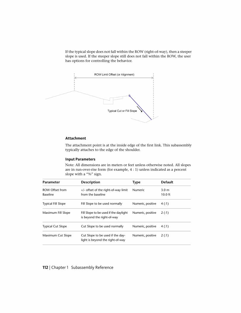
If the typical slope does not fall within the ROW (right-of-way), then a steeperslope is used. If the steeper slope still does not fall within the ROW, the userhas options for controlling the behavior.
Attachment
The attachment point is at the inside edge of the first link. This subassemblytypically attaches to the edge of the shoulder.
Input ParametersNote: All dimensions are in meters or feet unless otherwise noted. All slopesare in run-over-rise form (for example, 4 : 1) unless indicated as a percentslope with a “%” sign.
DefaultTypeDescriptionParameter
3.0 mNumeric+/- offset of the right-of-way limitfrom the baseline
ROW Offset fromBaseline 10.0 ft
4 (:1)Numeric, positiveFill Slope to be used normallyTypical Fill Slope
2 (:1)Numeric, positiveFill Slope to be used if the daylightis beyond the right-of-way
Maximum Fill Slope
4 (:1)Numeric, positiveCut Slope to be used normallyTypical Cut Slope
2 (:1)Numeric, positiveCut Slope to be used if the day-light is beyond the right-of-way
Maximum Cut Slope
112 | Chapter 1 Subassembly Reference

DefaultTypeDescriptionParameter
Hold MaximumSlope
ListSpecifies what to do if the slopeextends beyond the ROW offset.
Hold Slope
Choices are a list as follows: HoldMaximum Slope, Override Maxim-um Slope.
NoneList of options:None, Circular,Parabolic
Specifies to round off the daylightlink at the catch point.
Rounding Option
LengthList of options:Length, Radius
Specifies the parameter that isused for rounding
Rounding By
0.5 mNumeric, positiveSpecifies value for length of radiusRounding Parameter
6Numeric, positiveinteger
Specifies number of intermittentpoints on rounding links (Max 10links)
Rounding Tessellation
NoneStringSpecifies to place optional materiallining along daylight links. You canchoose All Links or None.
Place Lined Material
1 : 1SlopeSpecifies the slope limit untilwhich the associated material lin-ing is placed
Slope Limit 1
12 inchesNumeric, positiveSpecifies the thickness of the linedmaterial. This thickness is meas-ured perpendicular to the link.
Material 1 Thickness
Rip RapStringSpecifies the name of the materialapplied for lining along gradinglinks
Material 1 Name
2 : 1SlopeSpecifies the slope limit untilwhich the associated material lin-ing is placed
Slope Limit 2
DaylightInsideROW | 113

DefaultTypeDescriptionParameter
6 inchesNumeric, positiveSpecifies the thickness of the linedmaterial. This thickness is meas-ured perpendicular to the link.
Material 2 Thickness
Rip RapStringSpecifies the name of the materialapplied for lining along gradinglinks
Material 2 Name
4 : 1SlopeSpecifies the slope limit untilwhich the associated material lin-ing is placed
Slope Limit 3
4 inchesNumeric, positiveSpecifies the thickness of the linedmaterial. This thickness is meas-ured perpendicular to the link.
Material 3 Thickness
Seeded GrassStringSpecifies the name of the materialapplied for lining along gradinglinks
Material 3 Name
Target ParametersThis section lists the parameters in this subassembly that can be mapped toone or more target objects, such as a surface, alignment, or profile object ina drawing. For more information, see Setting Targets in the AutoCAD Civil3D User’s Guide Help.
StatusTypeParameter
OptionalMay be used to override the fixed ROW Offset andtie the ROW offset to an offset alignment. The fol-
ROW Offset
lowing object types can be used as targets forspecifying this: alignments, polylines, feature lines,or survey figures.
RequiredName of the daylighting surface. The followingobject types can be used as targets for specifyingthis surface: surfaces.
Daylight Surface
114 | Chapter 1 Subassembly Reference
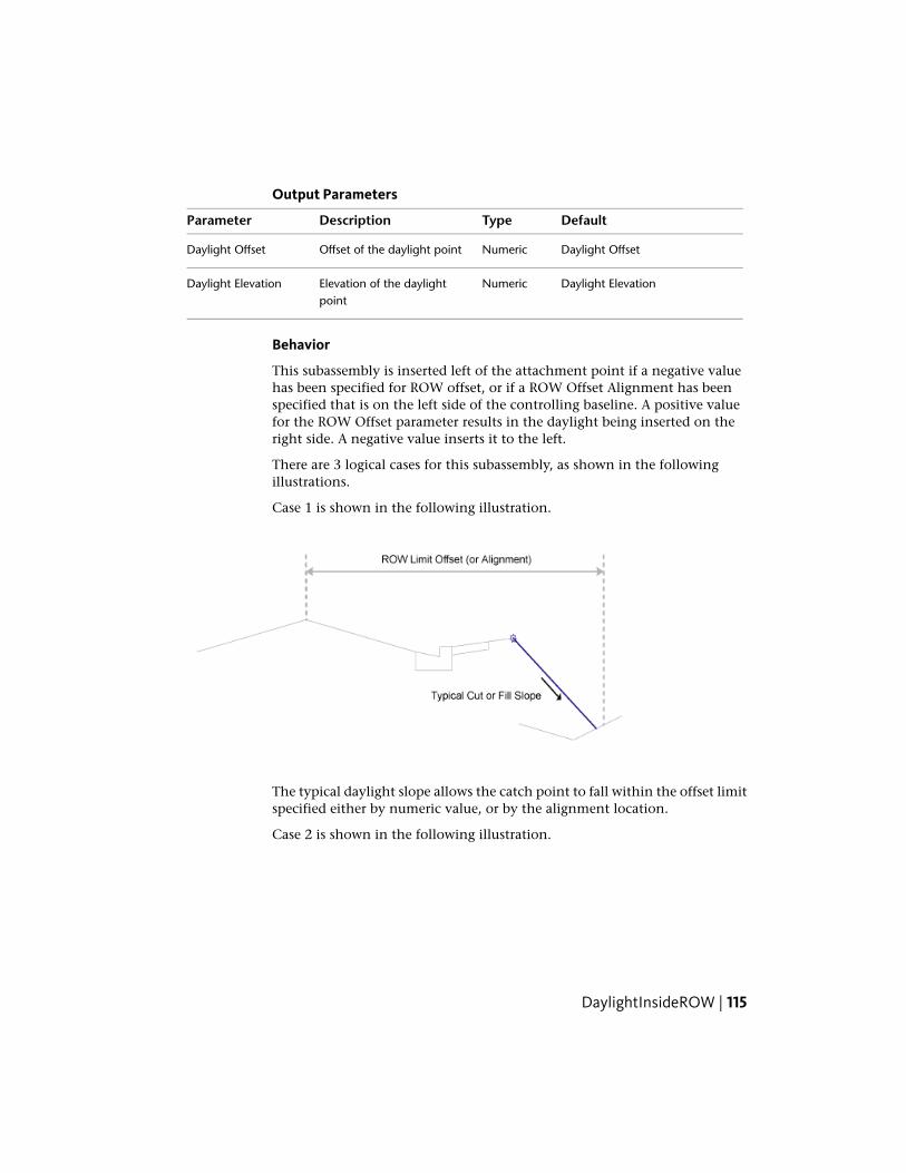
Output Parameters
DefaultTypeDescriptionParameter
Daylight OffsetNumericOffset of the daylight pointDaylight Offset
Daylight ElevationNumericElevation of the daylightpoint
Daylight Elevation
Behavior
This subassembly is inserted left of the attachment point if a negative valuehas been specified for ROW offset, or if a ROW Offset Alignment has beenspecified that is on the left side of the controlling baseline. A positive valuefor the ROW Offset parameter results in the daylight being inserted on theright side. A negative value inserts it to the left.
There are 3 logical cases for this subassembly, as shown in the followingillustrations.
Case 1 is shown in the following illustration.
The typical daylight slope allows the catch point to fall within the offset limitspecified either by numeric value, or by the alignment location.
Case 2 is shown in the following illustration.
DaylightInsideROW | 115

The typical daylight slope forces the catch point to fall outside the offset limitspecified either by numeric value or by the alignment location. If the HoldSlope input parameter is set to Hold Maximum Slope, the slope is increasedup to the maximum value. At this point the maximum slope is held and thecatch point will be beyond the ROW Limit.
Case 3 is shown in the following illustration.
The typical daylight slope forces the catch point to fall outside the offset limitspecified either by numeric value or the alignment location. If the Hold Slopeinput parameter is set to Override Maximum slope, the slope restrictions areignored, and the catch point is placed at the ROW offset location.
As with all daylight subassemblies, rounding and lined material controls areavailable with this subassembly.
NOTE In Civil 3D 2010 and previous versions, the Material Thickness parameterwas measured vertically. In Civil 3D 2011 and later, this parameter is measuredperpendicular to the link. Therefore, if you open a drawing containing thesesubassemblies that was created in Civil 3D 2010 or prior in Civil 3D 2011 or later,and then rebuild the corridor(s), this parameter will be changed to reflect the newbehavior. Any volume reports that use this subassembly will be updated to reflectthe new behavior.
Layout Mode Operation
In layout mode, this subassembly will display all links and use the typicalslope value specified in the input parameters.
116 | Chapter 1 Subassembly Reference

Point, Link, and Shape CodesThe following table lists the point, link, and shape codes for this subassemblythat have codes assigned to them. Point, link, or shape codes for thissubassembly that do not have codes assigned are not included in this table.
DescriptionCodesPoint, Link,or Shape
Hinge point. Hinge_Cut is used if the daylight linkhas an upward slope; Hinge_Fill is used if the daylightlink has a downward slope.
Hinge, Hinge_Cut or Hinge_FillP1
Daylight pointDaylight, Daylight_Cut or Day-light_Fill
P2
Daylight link for cut sectionTop, Datum, Daylight, Day-light_Cut, Slope_Link
L1
Daylight Link for fill sectionTop, Datum, Daylight, Day-light_Fill, Slope_Link
L1
Coding Diagram
DaylightMaxOffsetThis subassembly inserts a link that extends to a target surface at a user-definedcut or fill slope.
If necessary, the slope is adjusted to keep the daylight point within a maximum+/- offset from the baseline.
DaylightMaxOffset | 117

You can also specify optional lined materials for daylight and other links (AllLinks, Daylight Links, Fill Links Only, and None).
Attachment
The attachment point is at the hinge point of the daylight link. Thiscomponent can be attached to either the left or right side.
Input ParametersNote: All dimensions are in meters or feet unless otherwise noted. All slopesare in run-over-rise form (for example, 4 : 1) unless indicated as a percentslope with a “%” sign.
DefaultTypeDescriptionParameter
RightLeft / RightSpecifies which side to place thesubassembly
Side
4 ( : 1)Numeric, positiveThe slope for normal daylighting incut conditions
Cut Slope
4 ( : 1)Numeric, positiveThe slope for normal daylighting infill conditions
Fill Slope
118 | Chapter 1 Subassembly Reference

DefaultTypeDescriptionParameter
3.0 mNumericThe maximum allowable offset forthe daylight point
Max Offset fromBaseline 10.0 ft
NoneStringSpecifies to round off the daylightlink at the catch point
Rounding Option
LengthStringSpecifies what parameter is used forrounding
Rounding By
1.500 ftNumeric, positiveSpecifies value for length or radiusRounding Parameter
6Numeric, positiveSpecifies number of intermittentpoints on rounding links (maximum10 links)
Rounding Tesselation
NoneStringSpecifies to place optional materiallining along daylight links. You can
Place Lined Material
choose All Links, Daylight Links, FillLinks Only, and None.
1 : 1SlopeSpecifies the slope limit until whichthe associated material lining isplaced
Slope Limit 1
12 inchesNumeric, positiveSpecifies the thickness of lined ma-terial. This thickness is measuredperpendicular to the link.
Material 1 Thickness
Rip RapStringSpecifies the name of the materialapplies for lining along grading links
Material 1 Name
2 : 1SlopeSpecifies the slope limit until whichthe associated material lining isplaced
Slope Limit 2
6 inchesNumeric, positiveSpecifies the thickness of lined ma-terial. This thickness is measuredperpendicular to the link.
Material 2 Thickness
Rip RapStringSpecifies the name of the materialapplies for lining along grading links
Material 2 Name
DaylightMaxOffset | 119

DefaultTypeDescriptionParameter
4 : 1SlopeSpecifies the slope limit until whichthe associated material lining isplaced
Slope Limit 3
4 inchesNumeric, positiveSpecifies the thickness of lined ma-terial. This thickness is measuredperpendicular to the link.
Material 3 Thickness
Seeded GrassStringSpecifies the name of the materialapplies for lining along grading links
Material 3 Name
Target ParametersThis section lists the parameters in this subassembly that can be mapped toone or more target objects. For more information, see Setting Targets in theAutoCAD Civil 3D User’s Guide Help.
StatusDescriptionParameter
OptionalMay be used to override the fixed Max Offset valueand tie the maximum offset to an offset alignment.
Max Offset
The following object types can be used as targetsfor specifying the offset: alignments, polylines,feature lines, or survey figures.
RequiredName of the daylighting surface. The followingobject types can be used as targets for specifyingthe surface: surfaces.
Daylight Surface
Output Parameters
TypeDescriptionParameter
NumericOffset of the daylight point.Daylight Offset
NumericElevation of the daylight point.Daylight Elevation
Behavior
This subassembly attempts to calculate a daylight point for the cut condition.If a daylight point is found, its offset is compared to the Max Offset value. Ifthe Max Offset value is exceeded, the daylight point is moved to the maximum
120 | Chapter 1 Subassembly Reference

offset point on the target surface. If no cut daylight point is found, the processis repeated for the fill condition.
If an offset horizontal alignment name is assigned to the Max Offset duringcorridor modeling, the value of the Max Offset will vary to match the offsetof the alignment.
Like other daylight subassemblies, this subassembly optionally lets you adda lined material. You can specify three ranges of slopes. Material type 1 isapplied if the slope of the links is up to the specified slope value. From slope1 to slope 2, the second type of material applied. Similarly, if the slopes oflinks fall within slope 2 and slope 3 values, then material 3 is applied. If thelink slopes are flatter than slope limit 3, then no material is applied.
If a lined material is added to the subassembly, then parallel links are addedto the daylight links with specified thickness. This thickness parameter (forexample, Material 1 Thickness) is measured perpendicular to the link. Bottomlevel links are coded with Datum and daylight links are coded with Top. Shapesenclosed by these materials are coded with material name.
NOTE In Civil 3D 2010 and previous versions, the Material Thickness parameterwas measured vertically. In Civil 3D 2011 and later, this parameter is measuredperpendicular to the link. Therefore, if you open a drawing containing thesesubassemblies that was created in Civil 3D 2010 or prior in Civil 3D 2011 or later,and then rebuild the corridor(s), this parameter will be changed to reflect the newbehavior. Any volume reports that use this subassembly will be updated to reflectthe new behavior.
Layout Mode Operation
In layout mode, this subassembly displays both the cut and fill slopes in dashedlines extended outward for a distance of 3 meters or 10 feet. The daylight linksare terminated with arrowheads pointing outwards.
DaylightMaxOffset | 121
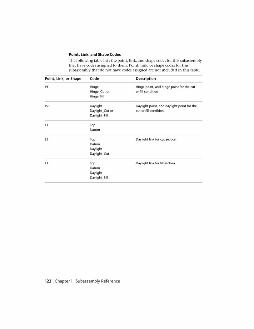
Point, Link, and Shape CodesThe following table lists the point, link, and shape codes for this subassemblythat have codes assigned to them. Point, link, or shape codes for thissubassembly that do not have codes assigned are not included in this table.
DescriptionCodePoint, Link, or Shape
Hinge point, and hinge point for the cutor fill condition
HingeHinge_Cut or
P1
Hinge_Fill
Daylight point, and daylight point for thecut or fill condition
DaylightDaylight_Cut or
P2
Daylight_Fill
TopL1Datum
Daylight link for cut sectionTopL1DatumDaylightDaylight_Cut
Daylight link for fill sectionTopL1DatumDaylightDaylight_Fill
122 | Chapter 1 Subassembly Reference

Coding Diagram
DaylightMaxWidthThis subassembly inserts a link that daylights to a target surface at auser-defined cut or fill slope.
If necessary, the slope is adjusted to keep the daylight point within a maximumwidth from the hinge point.
DaylightMaxWidth | 123

You can also specify optional lined materials for daylight and other links (AllLinks, Daylight Links, Fill Links Only, and None).
Attachment
The attachment point is at the hinge point of the daylight link. Thiscomponent can be attached to either the left or right side.
Input ParametersNote: All dimensions are in meters or feet unless otherwise noted. All slopesare in run-over-rise form (for example, 4 : 1) unless indicated as a percentslope with a “%” sign.
DefaultTypeDescriptionParameter
RightLeft / RightSpecifies which side to place the sub-assembly
Side
4 ( : 1)Numeric, positiveThe slope for normal daylighting in cutconditions
Cut Slope
4 ( : 1)Numeric, positiveThe slope for normal daylighting in fillconditions
Fill Slope
124 | Chapter 1 Subassembly Reference

DefaultTypeDescriptionParameter
3.0 mNumericThe maximum allowable width fromthe hinge point (attachment point) forthe daylight point
Max Width10.0 ft
NoneStringSpecifies to round off the daylight linkat the catch point
Rounding Option
LengthStringSpecifies what parameter is used forrounding
Rounding By
1.500 ftNumeric, positiveSpecifies value for length or radiusRounding Parameter
6Numeric, positiveSpecifies number of intermittent pointson rounding links (maximum 10 links)
Rounding Tesselation
NoneStringSpecifies to place optional material lin-ing along daylight links. You can choose
Place Lined Material
All Links, Daylight Links, Fill Links Only,and None.
1 : 1SlopeSpecifies the slope limit until which theassociated material lining is placed
Slope Limit 1
12 inchesNumeric, positiveSpecifies the thickness of lined material.This thickness is measured perpendicularto the link.
Material 1 Thickness
Rip RapStringSpecifies the name of the material ap-plies for lining along grading links
Material 1 Name
2 : 1SlopeSpecifies the slope limit until which theassociated material lining is placed
Slope Limit 2
6 inchesNumeric, positiveSpecifies the thickness of lined material.This thickness is measured perpendicularto the link.
Material 2 Thickness
Rip RapStringSpecifies the name of the material ap-plies for lining along grading links
Material 2 Name
DaylightMaxWidth | 125
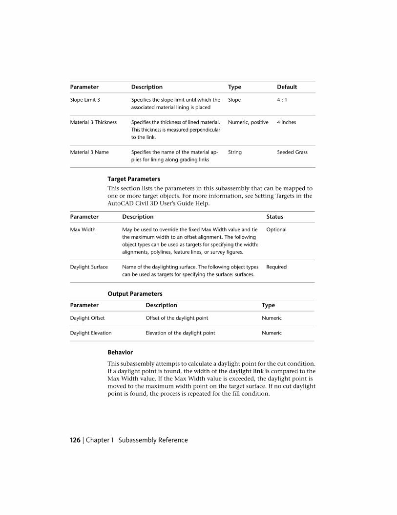
DefaultTypeDescriptionParameter
4 : 1SlopeSpecifies the slope limit until which theassociated material lining is placed
Slope Limit 3
4 inchesNumeric, positiveSpecifies the thickness of lined material.This thickness is measured perpendicularto the link.
Material 3 Thickness
Seeded GrassStringSpecifies the name of the material ap-plies for lining along grading links
Material 3 Name
Target ParametersThis section lists the parameters in this subassembly that can be mapped toone or more target objects. For more information, see Setting Targets in theAutoCAD Civil 3D User’s Guide Help.
StatusDescriptionParameter
OptionalMay be used to override the fixed Max Width value and tiethe maximum width to an offset alignment. The following
Max Width
object types can be used as targets for specifying the width:alignments, polylines, feature lines, or survey figures.
RequiredName of the daylighting surface. The following object typescan be used as targets for specifying the surface: surfaces.
Daylight Surface
Output Parameters
TypeDescriptionParameter
NumericOffset of the daylight pointDaylight Offset
NumericElevation of the daylight pointDaylight Elevation
Behavior
This subassembly attempts to calculate a daylight point for the cut condition.If a daylight point is found, the width of the daylight link is compared to theMax Width value. If the Max Width value is exceeded, the daylight point ismoved to the maximum width point on the target surface. If no cut daylightpoint is found, the process is repeated for the fill condition.
126 | Chapter 1 Subassembly Reference
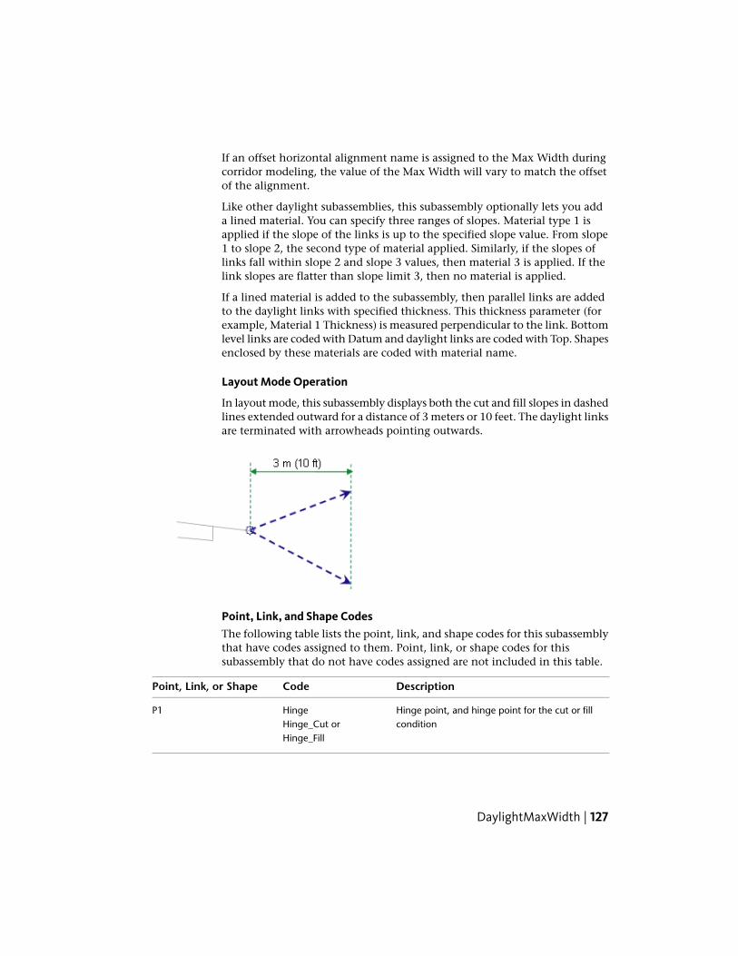
If an offset horizontal alignment name is assigned to the Max Width duringcorridor modeling, the value of the Max Width will vary to match the offsetof the alignment.
Like other daylight subassemblies, this subassembly optionally lets you adda lined material. You can specify three ranges of slopes. Material type 1 isapplied if the slope of the links is up to the specified slope value. From slope1 to slope 2, the second type of material applied. Similarly, if the slopes oflinks fall within slope 2 and slope 3 values, then material 3 is applied. If thelink slopes are flatter than slope limit 3, then no material is applied.
If a lined material is added to the subassembly, then parallel links are addedto the daylight links with specified thickness. This thickness parameter (forexample, Material 1 Thickness) is measured perpendicular to the link. Bottomlevel links are coded with Datum and daylight links are coded with Top. Shapesenclosed by these materials are coded with material name.
Layout Mode Operation
In layout mode, this subassembly displays both the cut and fill slopes in dashedlines extended outward for a distance of 3 meters or 10 feet. The daylight linksare terminated with arrowheads pointing outwards.
Point, Link, and Shape CodesThe following table lists the point, link, and shape codes for this subassemblythat have codes assigned to them. Point, link, or shape codes for thissubassembly that do not have codes assigned are not included in this table.
DescriptionCodePoint, Link, or Shape
Hinge point, and hinge point for the cut or fillcondition
HingeHinge_Cut or
P1
Hinge_Fill
DaylightMaxWidth | 127

DescriptionCodePoint, Link, or Shape
Daylight point, and daylight point for the cutor fill condition
DaylightDaylight_Cut or
P2
Daylight_Fill
TopL1Datum
Daylight link for cut sectionTopL1DatumDaylightDaylight_Cut
Daylight link for fill sectionTopL1DatumDaylightDaylight_Fill
Coding Diagram
128 | Chapter 1 Subassembly Reference

DaylightMinOffsetThis subassembly inserts a link that daylights to a target surface at auser-defined cut or fill slope.
If necessary, the slope is adjusted to keep the daylight point beyond aminimum offset from the baseline.
You can also specify optional lined materials for daylight and other links (AllLinks, Daylight Links, Fill Links Only, and None).
Attachment
The attachment point is at the hinge point of the daylight link. Thiscomponent can be attached to either the left or right side.
DaylightMinOffset | 129
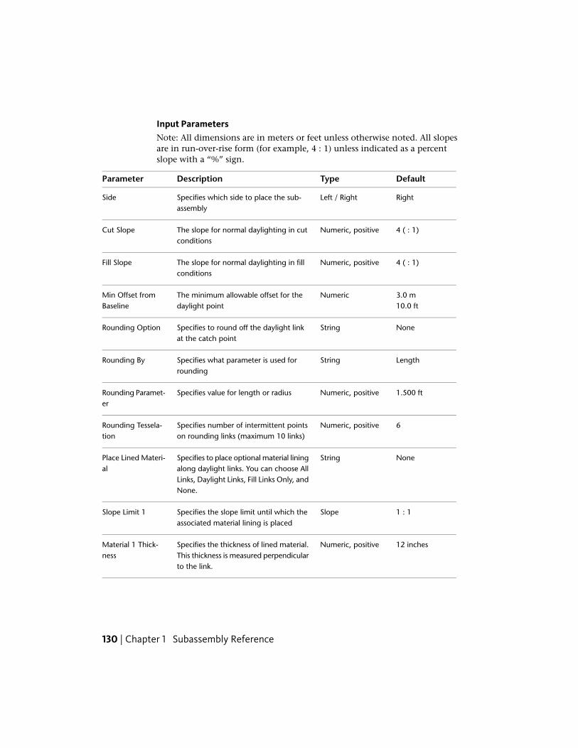
Input ParametersNote: All dimensions are in meters or feet unless otherwise noted. All slopesare in run-over-rise form (for example, 4 : 1) unless indicated as a percentslope with a “%” sign.
DefaultTypeDescriptionParameter
RightLeft / RightSpecifies which side to place the sub-assembly
Side
4 ( : 1)Numeric, positiveThe slope for normal daylighting in cutconditions
Cut Slope
4 ( : 1)Numeric, positiveThe slope for normal daylighting in fillconditions
Fill Slope
3.0 mNumericThe minimum allowable offset for thedaylight point
Min Offset fromBaseline 10.0 ft
NoneStringSpecifies to round off the daylight linkat the catch point
Rounding Option
LengthStringSpecifies what parameter is used forrounding
Rounding By
1.500 ftNumeric, positiveSpecifies value for length or radiusRounding Paramet-er
6Numeric, positiveSpecifies number of intermittent pointson rounding links (maximum 10 links)
Rounding Tessela-tion
NoneStringSpecifies to place optional material liningalong daylight links. You can choose All
Place Lined Materi-al
Links, Daylight Links, Fill Links Only, andNone.
1 : 1SlopeSpecifies the slope limit until which theassociated material lining is placed
Slope Limit 1
12 inchesNumeric, positiveSpecifies the thickness of lined material.This thickness is measured perpendicularto the link.
Material 1 Thick-ness
130 | Chapter 1 Subassembly Reference

DefaultTypeDescriptionParameter
Rip RapStringSpecifies the name of the material ap-plies for lining along grading links
Material 1 Name
2 : 1SlopeSpecifies the slope limit until which theassociated material lining is placed
Slope Limit 2
6 inchesNumeric, positiveSpecifies the thickness of lined material.This thickness is measured perpendicularto the link.
Material 2 Thick-ness
Rip RapStringSpecifies the name of the material ap-plies for lining along grading links
Material 2 Name
4 : 1SlopeSpecifies the slope limit until which theassociated material lining is placed
Slope Limit 3
4 inchesNumeric, positiveSpecifies the thickness of lined material.This thickness is measured perpendicularto the link.
Material 3 Thick-ness
Seeded GrassStringSpecifies the name of the material ap-plies for lining along grading links
Material 3 Name
Target ParametersThis section lists the parameters in this subassembly that can be mapped toone or more target objects. For more information, see Setting Targets in theAutoCAD Civil 3D User’s Guide Help.
StatusDescriptionParameter
OptionalMay be used to override the fixed Min Offset and tie theminimum offset to an offset alignment. The following object
Min Offset
types can be used as targets for specifying the offset: align-ments, polylines, feature lines, or survey figures.
RequiredName of the daylighting surface. The following object typescan be used as targets for specifying the surface: surfaces.
Daylight Surface
DaylightMinOffset | 131

Output Parameters
TypeDescriptionParameter
NumericOffset of the daylight pointDaylight Offset
NumericElevation of the daylight pointDaylight Elevation
Behavior
This subassembly attempts to calculate a daylight point for the cut condition.If a daylight point is found, its offset is compared to the Min Offset value. Ifthe daylight point is within the Min Offset, the daylight point is moved tothe minimum offset point on the target surface. If no cut daylight point isfound, the process is repeated for the fill condition.
If an offset horizontal alignment name is assigned to the Min Offset duringcorridor modeling, the value of the Min Offset will vary to match the offsetof the alignment.
Like other daylight subassemblies, this subassembly optionally lets you adda lined material. You can specify three ranges of slopes. Material type 1 isapplied if the slope of the links is up to the specified slope value. From slope1 to slope 2, the second type of material applied. Similarly, if the slopes oflinks fall within slope 2 and slope 3 values, then material 3 is applied. If thelink slopes are flatter than slope limit 3, then no material is applied.
If a lined material is added to the subassembly, then parallel links are addedto the daylight links with specified thickness. This thickness parameter (forexample, Material 1 Thickness) is measured perpendicular to the link. Bottomlevel links are coded with Datum and daylight links are coded with Top. Shapesenclosed by these materials are coded with material name.
NOTE In Civil 3D 2010 and previous versions, the Material Thickness parameterwas measured vertically. In Civil 3D 2011 and later, this parameter is measuredperpendicular to the link. Therefore, if you open a drawing containing thesesubassemblies that was created in Civil 3D 2010 or prior in Civil 3D 2011 or later,and then rebuild the corridor(s), this parameter will be changed to reflect the newbehavior. Any volume reports that use this subassembly will be updated to reflectthe new behavior.
Layout Mode Operation
In layout mode, this subassembly displays both the cut and fill slopes in dashedlines extended outward for the Min Offset distance. The daylight links areterminated with arrowheads pointing outwards.
132 | Chapter 1 Subassembly Reference

Point, Link, and Shape CodesThe following table lists the point, link, and shape codes for this subassemblythat have codes assigned to them. Point, link, or shape codes for thissubassembly that do not have codes assigned are not included in this table.
DescriptionCodePoint, Link, or Shape
Hinge point, either for the cut or fill condi-tion
HingeHinge_Cut or
P1
Hinge_Fill
Daylight point, and daylight point for eitherthe cut or fill condition
DaylightDaylight_Cut or
P2
Daylight_Fill
TopL1Datum
Daylight link for cut sectionTopL1DatumDaylightDaylight_Cut
Daylight link for fill sectionTopL1DatumDaylightDaylight_Fill
DaylightMinOffset | 133

Coding Diagram
DaylightMinWidthThis subassembly inserts a link that daylights to a target surface at auser-defined cut or fill slope.
If necessary, the slope is adjusted to keep the daylight point beyond aminimum width from the hinge point.
134 | Chapter 1 Subassembly Reference

You can also specify optional lined materials for daylight and other links (AllLinks, Daylight Links, Fill Links Only, and None).
Attachment
The attachment point is at the hinge point of the daylight link. Thiscomponent can be attached to either the left or right side.
Input ParametersNote: All dimensions are in meters or feet unless otherwise noted. All slopesare in run-over-rise form (for example, 4 : 1) unless indicated as a percentslope with a “%” sign.
DefaultTypeDescriptionParameter
RightLeft / RightSpecifies which side to place the subassemblySide
4 ( : 1)Numeric, posit-ive
The slope for normal daylighting in cut con-ditions
Cut Slope
4 ( : 1)Numeric, posit-ive
The slope for normal daylighting in fill condi-tions
Fill Slope
DaylightMinWidth | 135

DefaultTypeDescriptionParameter
3.0 mNumericThe minimum allowable offset for the day-light point
Min Width10.0 ft
NoneStringSpecifies to round off the daylight link at thecatch point
Rounding Option
LengthStringSpecifies what parameter is used for roundingRounding By
1.500 ftNumeric, posit-ive
Specifies value for length or radiusRounding Paramet-er
6Numeric, posit-ive
Specifies number of intermittent points onrounding links (maximum 10 links)
Rounding Tessela-tion
NoneStringSpecifies to place optional material liningalong daylight links. You can choose All Links,Daylight Links, Fill Links Only, and None.
Place Lined Materi-al
1 : 1SlopeSpecifies the slope limit until which the asso-ciated material lining is placed
Slope Limit 1
12 inchesNumeric, posit-ive
Specifies the thickness of lined material. Thisthickness is measured perpendicular to thelink.
Material 1 Thick-ness
Rip RapStringSpecifies the name of the material applies forlining along grading links
Material 1 Name
2 : 1SlopeSpecifies the slope limit until which the asso-ciated material lining is placed
Slope Limit 2
6 inchesNumeric, posit-ive
Specifies the thickness of lined material. Thisthickness is measured perpendicular to thelink.
Material 2 Thick-ness
Rip RapStringSpecifies the name of the material applies forlining along grading links
Material 2 Name
4 : 1SlopeSpecifies the slope limit until which the asso-ciated material lining is placed
Slope Limit 3
136 | Chapter 1 Subassembly Reference

DefaultTypeDescriptionParameter
4 inchesNumeric, posit-ive
Specifies the thickness of lined material. Thisthickness is measured perpendicular to thelink.
Material 3 Thick-ness
Seeded GrassStringSpecifies the name of the material applies forlining along grading links
Material 3 Name
Target ParametersThis section lists the parameters in this subassembly that can be mapped toone or more target objects. For more information, see Setting Targets in theAutoCAD Civil 3D User’s Guide Help.
StatusDescriptionParameter
OptionalMay be used to override the fixed Min Width and tie theminimum width to an offset alignment. The following ob-
Min Width
ject types can be used as targets for specifying the width:alignments, polylines, feature lines, or survey figures.
RequiredName of the daylighting surface. The following object typescan be used as targets for specifying the surface: surfaces.
Daylight Surface
Output Parameters
TypeDescriptionParameter
NumericOffset of the daylight pointDaylight Offset
NumericElevation of the daylight pointDaylight Elevation
Behavior
This subassembly attempts to calculate a daylight point for the cut condition.If a daylight point is found, the width of the daylight link is compared to theMin Width value. If the daylight point is within the Min Width, the daylightpoint is moved to the minimum width point on the target surface. If no cutdaylight point is found, the process is repeated for the fill condition.
If an offset horizontal alignment name is assigned to the Min Width duringcorridor modeling, the value of the Min Width will vary to match the offsetof the alignment.
DaylightMinWidth | 137

Like other daylight subassemblies, this subassembly optionally lets you adda lined material. You can specify three ranges of slopes. Material type 1 isapplied if the slope of the links is up to the specified slope value. From slope1 to slope 2, the second type of material applied. Similarly, if the slopes oflinks fall within slope 2 and slope 3 values, then material 3 is applied. If thelink slopes are flatter than slope limit 3, then no material is applied.
If a lined material is added to the subassembly, then parallel links are addedto the daylight links with specified thickness. This thickness parameter (forexample, Material 1 Thickness) is measured perpendicular to the link. Bottomlevel links are coded with Datum and daylight links are coded with Top. Shapesenclosed by these materials are coded with material name.
NOTE In Civil 3D 2010 and previous versions, the Material Thickness parameterwas measured vertically. In Civil 3D 2011 and later, this parameter is measuredperpendicular to the link. Therefore, if you open a drawing containing thesesubassemblies that was created in Civil 3D 2010 or prior in Civil 3D 2011 or later,and then rebuild the corridor(s), this parameter will be changed to reflect the newbehavior. Any volume reports that use this subassembly will be updated to reflectthe new behavior.
Layout Mode Operation
In layout mode, this subassembly displays both the cut and fill slopes in dashedlines extended outward for the Min Width distance. The daylight links areterminated with arrowheads pointing outwards.
138 | Chapter 1 Subassembly Reference

Point, Link, and Shape CodesThe following table lists the point, link, and shape codes for this subassemblythat have codes assigned to them. Point, link, or shape codes for thissubassembly that do not have codes assigned are not included in this table.
DescriptionCodePoint, Link, or Shape
Hinge point, either for the cut or fill conditionHingeP1Hinge_Cut orHinge_Fill
Daylight point, and daylight point for eitherthe cut or fill condition
DaylightDaylight_Cut or
P2
Daylight_Fill
TopL1Datum
Daylight link for cut sectionTopL1DatumDaylightDaylight_Cut
Daylight link for fill sectionTopL1DatumDaylightDaylight_Fill
DaylightMinWidth | 139
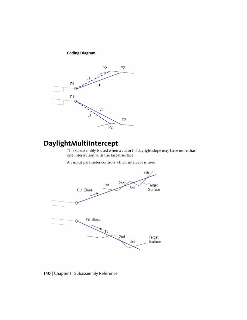
Coding Diagram
DaylightMultiInterceptThis subassembly is used when a cut or fill daylight slope may have more thanone intersection with the target surface.
An input parameter controls which intercept is used.
140 | Chapter 1 Subassembly Reference

You can also specify optional lined materials for daylight and other links (AllLinks, Daylight Links, Fill Links Only, and None).
Attachment
The attachment point is at the hinge point of the daylight link. Thiscomponent can be attached to either the left or right side.
Input ParametersNote: All dimensions are in meters or feet unless otherwise noted. All slopesare in run-over-rise form (for example, 4 : 1) unless indicated as a percentslope with a “%” sign.
DefaultTypeDescriptionParameter
RightLeft / RightSpecifies which side to place the subassemblySide
4 ( : 1)Numeric, posit-ive
The slope for normal daylighting in cut conditionsCut Slope
4 ( : 1)Numeric, posit-ive
The slope for normal daylighting in fill conditionsFill Slope
10Numeric, posit-ive, integer
The number of the intercept to save. If the Inter-cept Number value is greater than the actual
Intercept Num-ber
number of intercepts, the highest intercept foundis used
NoneStringSpecifies to round off the daylight link at the catchpoint
Rounding Op-tion
LengthStringSpecifies what parameter is used for roundingRounding By
1.500 ftNumeric, posit-ive
Specifies value for length or radiusRounding Para-meter
6Numeric, posit-ive
Specifies number of intermittent points onrounding links (maximum 10 links)
Rounding Tes-selation
NoneStringSpecifies to place optional material lining alongdaylight links. You can choose All Links, DaylightLinks, Fill Links Only, and None.
Place Lined Ma-terial
DaylightMultiIntercept | 141

DefaultTypeDescriptionParameter
1 : 1SlopeSpecifies the slope limit until which the associatedmaterial lining is placed
Slope Limit 1
12 inchesNumeric, posit-ive
Specifies the thickness of lined material. Thisthickness is measured perpendicular to the link.
Material 1Thickness
Rip RapStringSpecifies the name of the material applies for lin-ing along grading links
Material 1Name
2 : 1SlopeSpecifies the slope limit until which the associatedmaterial lining is placed
Slope Limit 2
6 inchesNumeric, posit-ive
Specifies the thickness of lined material. Thisthickness is measured perpendicular to the link.
Material 2Thickness
Rip RapStringSpecifies the name of the material applies for lin-ing along grading links
Material 2Name
4 : 1SlopeSpecifies the slope limit until which the associatedmaterial lining is placed
Slope Limit 3
4 inchesNumeric, posit-ive
Specifies the thickness of lined material. Thisthickness is measured perpendicular to the link.
Material 3Thickness
SeededGrass
StringSpecifies the name of the material applies for lin-ing along grading links
Material 3Name
Target ParametersThis section lists the parameters in this subassembly that can be mapped toone or more target objects. For more information, see Setting Targets in theAutoCAD Civil 3D User’s Guide Help.
StatusDescriptionParameter
RequiredName of the daylighting surface. The following objecttypes can be used as targets for specifying the surface:surfaces.
Daylight Surface
142 | Chapter 1 Subassembly Reference
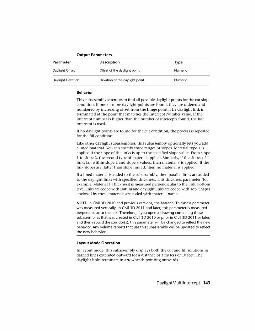
Output Parameters
TypeDescriptionParameter
NumericOffset of the daylight pointDaylight Offset
NumericElevation of the daylight pointDaylight Elevation
Behavior
This subassembly attempts to find all possible daylight points for the cut slopecondition. If one or more daylight points are found, they are ordered andnumbered by increasing offset from the hinge point. The daylight link isterminated at the point that matches the Intercept Number value. If theintercept number is higher than the number of intercepts found, the lastintercept is used.
If no daylight points are found for the cut condition, the process is repeatedfor the fill condition.
Like other daylight subassemblies, this subassembly optionally lets you adda lined material. You can specify three ranges of slopes. Material type 1 isapplied if the slope of the links is up to the specified slope value. From slope1 to slope 2, the second type of material applied. Similarly, if the slopes oflinks fall within slope 2 and slope 3 values, then material 3 is applied. If thelink slopes are flatter than slope limit 3, then no material is applied.
If a lined material is added to the subassembly, then parallel links are addedto the daylight links with specified thickness. This thickness parameter (forexample, Material 1 Thickness) is measured perpendicular to the link. Bottomlevel links are coded with Datum and daylight links are coded with Top. Shapesenclosed by these materials are coded with material name.
NOTE In Civil 3D 2010 and previous versions, the Material Thickness parameterwas measured vertically. In Civil 3D 2011 and later, this parameter is measuredperpendicular to the link. Therefore, if you open a drawing containing thesesubassemblies that was created in Civil 3D 2010 or prior in Civil 3D 2011 or later,and then rebuild the corridor(s), this parameter will be changed to reflect the newbehavior. Any volume reports that use this subassembly will be updated to reflectthe new behavior.
Layout Mode Operation
In layout mode, this subassembly displays both the cut and fill solutions indashed lines extended outward for a distance of 3 meters or 10 feet. Thedaylight links terminate in arrowheads pointing outwards.
DaylightMultiIntercept | 143
Point, Link, and Shape CodesThe following table lists the point, link, and shape codes for this subassemblythat have codes assigned to them. Point, link, or shape codes for thissubassembly that do not have codes assigned are not included in this table.
DescriptionCodePoint, Link, or Shape
Hinge point, either for the cut or fill conditionHingeP1Hinge_Cut orHinge_Fill
Daylight point, and daylight point for either thecut or fill condition
DaylightDaylight_Cut or
P2
Daylight_Fill
Daylight link for cut sectionTopL1DatumDaylightDaylight_Cut
Daylight link for fill sectionTopL1DatumDaylightDaylight_Fill
144 | Chapter 1 Subassembly Reference

Coding Diagram
DaylightMultipleSurfaceThis subassembly lets you specify three surface layers and cut slopes for eachmaterial type.
When transitioning between types, a bench can also be inserted.
Attachment
The attachment point is at the inside edge of the initial cut or fill slope. Thiscomponent can be attached to either the left or right side.
DaylightMultipleSurface | 145
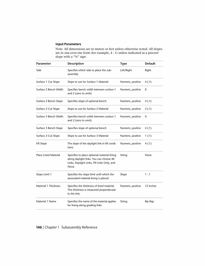
Input ParametersNote: All dimensions are in meters or feet unless otherwise noted. All slopesare in run-over-rise form (for example, 4 : 1) unless indicated as a percentslope with a “%” sign.
DefaultTypeDescriptionParameter
RightLeft/RightSpecifies which side to place the sub-assembly
Side
4 (:1)Numeric, positiveSlope to use for Surface 1 MaterialSurface 1 Cut Slope
0Numeric, positiveSpecifies bench width between surface 1and 2 (zero to omit)
Surface 2 Bench Width
4 (:1)Numeric, positiveSpecifies slope of optional benchSurface 2 Bench Slope
2 (:1)Numeric, positiveSlope to use for Surface 2 MaterialSurface 2 Cut Slope
0Numeric, positiveSpecifies bench width between surface 1and 2 (zero to omit)
Surface 3 Bench Width
4 (:1)Numeric, positiveSpecifies slope of optional benchSurface 3 Bench Slope
1 (:1)Numeric, positiveSlope to use for Surface 3 MaterialSurface 3 Cut Slope
4 (:1)Numeric, positiveThe slope of the daylight link in fill condi-tions
Fill Slope
NoneStringSpecifies to place optional material liningalong daylight links. You can choose All
Place Lined Material
Links, Daylight Links, Fill Links Only, andNone.
1 : 1SlopeSpecifies the slope limit until which theassociated material lining is placed
Slope Limit 1
12 inchesNumeric, positiveSpecifies the thickness of lined material.This thickness is measured perpendicularto the link.
Material 1 Thickness
Rip RapStringSpecifies the name of the material appliesfor lining along grading links
Material 1 Name
146 | Chapter 1 Subassembly Reference
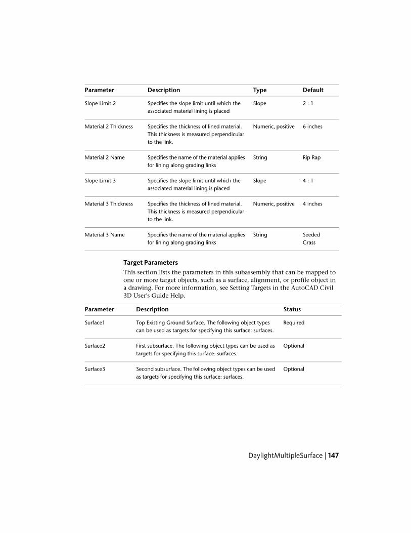
DefaultTypeDescriptionParameter
2 : 1SlopeSpecifies the slope limit until which theassociated material lining is placed
Slope Limit 2
6 inchesNumeric, positiveSpecifies the thickness of lined material.This thickness is measured perpendicularto the link.
Material 2 Thickness
Rip RapStringSpecifies the name of the material appliesfor lining along grading links
Material 2 Name
4 : 1SlopeSpecifies the slope limit until which theassociated material lining is placed
Slope Limit 3
4 inchesNumeric, positiveSpecifies the thickness of lined material.This thickness is measured perpendicularto the link.
Material 3 Thickness
SeededGrass
StringSpecifies the name of the material appliesfor lining along grading links
Material 3 Name
Target ParametersThis section lists the parameters in this subassembly that can be mapped toone or more target objects, such as a surface, alignment, or profile object ina drawing. For more information, see Setting Targets in the AutoCAD Civil3D User’s Guide Help.
StatusDescriptionParameter
RequiredTop Existing Ground Surface. The following object typescan be used as targets for specifying this surface: surfaces.
Surface1
OptionalFirst subsurface. The following object types can be used astargets for specifying this surface: surfaces.
Surface2
OptionalSecond subsurface. The following object types can be usedas targets for specifying this surface: surfaces.
Surface3
DaylightMultipleSurface | 147

Output Parameters
DefaultTypeDescriptionParameter
Daylight OffsetNumericOffset of the daylight pointDaylight Offset
Daylight ElevationNumericElevation of the daylight pointDaylight Elevation
Behavior
In a fill situation, a daylight link is inserted with a slope based on the fill slopeinput parameter to surface 1. In cut, the subassembly first checks to determineif it is below surface 3 by applying the surface 3 slope, and checking forintersection. This process repeats for each additional surface. Optionally,between the surfaces optional transitions can be added at the surface changes.The bench width and slope for the surface that was just intersected will beused.
NOTE In Civil 3D 2010 and previous versions, the Material Thickness parameterwas measured vertically. In Civil 3D 2011 and later, this parameter is measuredperpendicular to the link. Therefore, if you open a drawing containing thesesubassemblies that was created in Civil 3D 2010 or prior in Civil 3D 2011 or later,and then rebuild the corridor(s), this parameter will be changed to reflect the newbehavior. Any volume reports that use this subassembly will be updated to reflectthe new behavior.
Layout Mode Operation
This subassembly displays in layout mode using the input parameters forSurface 1 Slope and Fill Slope.
Point, Link, and Shape CodesThe following table lists the point, link, and shape codes for this subassemblythat have codes assigned to them. Point, link, or shape codes for thissubassembly that do not have codes assigned are not included in this table.
DescriptionCodesPoint, Link, orShape
Hinge point. Hinge_Cut is used if the daylight linkhas an upward slope; Hinge_Fill is used if the day-light link has a downward slope.
Hinge, Hinge_Cut or Hinge_FillP1
148 | Chapter 1 Subassembly Reference

DescriptionCodesPoint, Link, orShape
Daylight pointDaylight, Daylight_Cut or Day-light_Fill
P2
Daylight pointDaylight, Daylight_CutP3-P6
Top, Datum, Slope_LinkL1
Daylight link for Cut sectionDaylight, Daylight_CutL1
Daylight link for Fill sectionDaylight, Daylight_FillL1
Links for slopes through surfacesTop, Datum, Slope_Link, Day-light_Cut
L2-L5
Last LinkTop, Datum, Daylight, DaylightCut
L Last
Coding Diagram
DaylightRockCutThis subassembly lets you select both an existing ground surface and a rocksurface as targets.
Depending on the position (above or below), the daylight will use varied slopesand ditching solutions. In fill and non-rock-cut conditions, this subassemblywill behave the same as the BasicSideslopeCutDitch subassembly.
DaylightRockCut | 149

Attachment
The attachment point is at the inside edge of the ditch foreslope for cutconditions, and at the inside edge of the daylight link for fill conditions.
Input ParametersNote: All dimensions are in meters or feet unless otherwise noted. All slopesare in run-over-rise form (for example, 4 : 1) unless indicated as a percentslope with a “%” sign.
DefaultTypeDescriptionParameter
RightLeft / RightSpecifies which side to place the subassemblySide
IncludeInclude / OmitIncludes or omits the Daylight linkDaylight Link
2 ( : 1)Numeric, positiveSlope of the daylight link for cut in Non RockCut Slope
150 | Chapter 1 Subassembly Reference
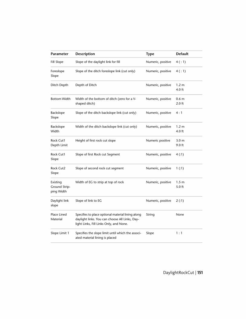
DefaultTypeDescriptionParameter
4 ( : 1)Numeric, positiveSlope of the daylight link for fillFill Slope
4 ( : 1)Numeric, positiveSlope of the ditch foreslope link (cut only)ForeslopeSlope
1.2 mNumeric, positiveDepth of DitchDitch Depth4.0 ft
0.6 mNumeric, positiveWidth of the bottom of ditch (zero for a V-shaped ditch)
Bottom Width2.0 ft
4 : 1Numeric, positiveSlope of the ditch backslope link (cut only)BackslopeSlope
1.2 mNumeric, positiveWidth of the ditch backslope link (cut only)BackslopeWidth 4.0 ft
3.0 mNumeric positiveHeight of first rock cut slopeRock Cut1Depth Limit 9.0 ft
4 (:1)Numeric, positiveSlope of first Rock cut SegmentRock Cut1Slope
1 (:1)Numeric, positiveSlope of second rock cut segmentRock Cut2Slope
1.5 mNumeric, positiveWidth of EG to strip at top of rockExistingGround Strip-ping Width
5.0 ft
2 (:1)Numeric, positiveSlope of link to EGDaylight linkslope
NoneStringSpecifies to place optional material lining alongdaylight links. You can choose All Links, Day-light Links, Fill Links Only, and None.
Place LinedMaterial
1 : 1SlopeSpecifies the slope limit until which the associ-ated material lining is placed
Slope Limit 1
DaylightRockCut | 151

DefaultTypeDescriptionParameter
12 inchesNumeric, positiveSpecifies the thickness of lined material. Thisthickness is measured perpendicular to the link.
Material 1Thickness
Rip RapStringSpecifies the name of the material applies forlining along grading links
Material 1Name
2 : 1SlopeSpecifies the slope limit until which the associ-ated material lining is placed
Slope Limit 2
6 inchesNumeric, positiveSpecifies the thickness of lined material. Thisthickness is measured perpendicular to the link.
Material 2Thickness
Rip RapStringSpecifies the name of the material applies forlining along grading links
Material 2Name
4 : 1SlopeSpecifies the slope limit until which the associ-ated material lining is placed
Slope Limit 3
4 inchesNumeric, positiveSpecifies the thickness of lined material. Thisthickness is measured perpendicular to the link.
Material 3Thickness
Seeded GrassStringSpecifies the name of the material applies forlining along grading links
Material 3Name
Target ParametersThis section lists the parameters in this subassembly that can be mapped toone or more target objects, such as a surface, alignment, or profile object ina drawing. For more information, see Setting Targets in the AutoCAD Civil3D User’s Guide Help.
StatusDescriptionParameter
RequiredName of the existing ground surface for daylight-ing. The following object types can be used astargets for specifying this surface: surfaces.
Existing GroundSurface
OptionalRock surface for rock cut. The following objecttypes can be used as targets for specifying thissurface: surfaces.
Rock Surface
152 | Chapter 1 Subassembly Reference

Output Parameters
None.
Behavior
The attachment point is tested to determine if it is in cut or fill. If it is in fill,the fill daylight link is extended to the Existing Surface at the given Fill Slope.
If Point P1 or P2 are below the rock surface then the foreslope, ditch bottom,and backslope are added, the rock cut1 link is added at the height specifiedby Rock Cut1 Depth Limit. A second rock cut link is added until it reachesthe rock surface at the Rock Cut 2 Slope. A stripped area is created as links arecreated that follow the rock surface for the specified buffer distance. Finallya daylight link to existing ground is inserted using the slope specified by theDaylight link Slope parameter.
If the daylight is not below the rock surface, the foreslope, ditch bottom, andbackslope are added, and the cut daylight link is extended from the end ofthe backslope to the Daylight Surface at the given Cut Slope.
DaylightRockCut | 153

This subassembly optionally lets you add a lined material. The materialthickness parameter (for example, Material 1 Thickness) is measuredperpendicular to the link.You can specify three ranges of slopes. Material type1 is applied if the slope of the links is up to the specified slope value. Fromslope 1 to slope 2, the second type of material applied. Similarly, if the slopesof links fall within slope 2 and slope 3 values, then material 3 is applied. Ifthe link slopes are flatter than slope limit 3, then no material is applied.
If a lined material is added to the subassembly, then parallel links are addedto the daylight links with specified thickness. This thickness parameter (forexample, Material 1 Thickness) is measured perpendicular to the link. Bottomlevel links are coded with Datum and daylight links are coded with Top. Shapesenclosed by these materials are coded with material name.
NOTE In Civil 3D 2010 and previous versions, the Material Thickness parameterwas measured vertically. In Civil 3D 2011 and later, this parameter is measuredperpendicular to the link. Therefore, if you open a drawing containing thesesubassemblies that was created in Civil 3D 2010 or prior in Civil 3D 2011 or later,and then rebuild the corridor(s), this parameter will be changed to reflect the newbehavior. Any volume reports that use this subassembly will be updated to reflectthe new behavior.
Layout Mode Operation
In layout mode the subassembly will use the same layout behavior as theexisting basicsideslopecutditch.
Point, Link, and Shape CodesThe following table lists the point, link, and shape codes for this subassemblythat have codes assigned to them. Point, link, or shape codes for thissubassembly that do not have codes assigned are not included in this table.
DescriptionCodesPoint,Link, orShape
Fill condition only - hinge point for fill daylight linkHinge, Hinge_FillP1
Cut condition only - inside edge of ditch Fill conditiononly - daylight point
Ditch_In, Daylight, Daylight_FillP2
Cut condition only - outside edge of ditchDitch_OutP3
Cut condition only - hinge point for cut daylight linkHinge_CutP4
154 | Chapter 1 Subassembly Reference
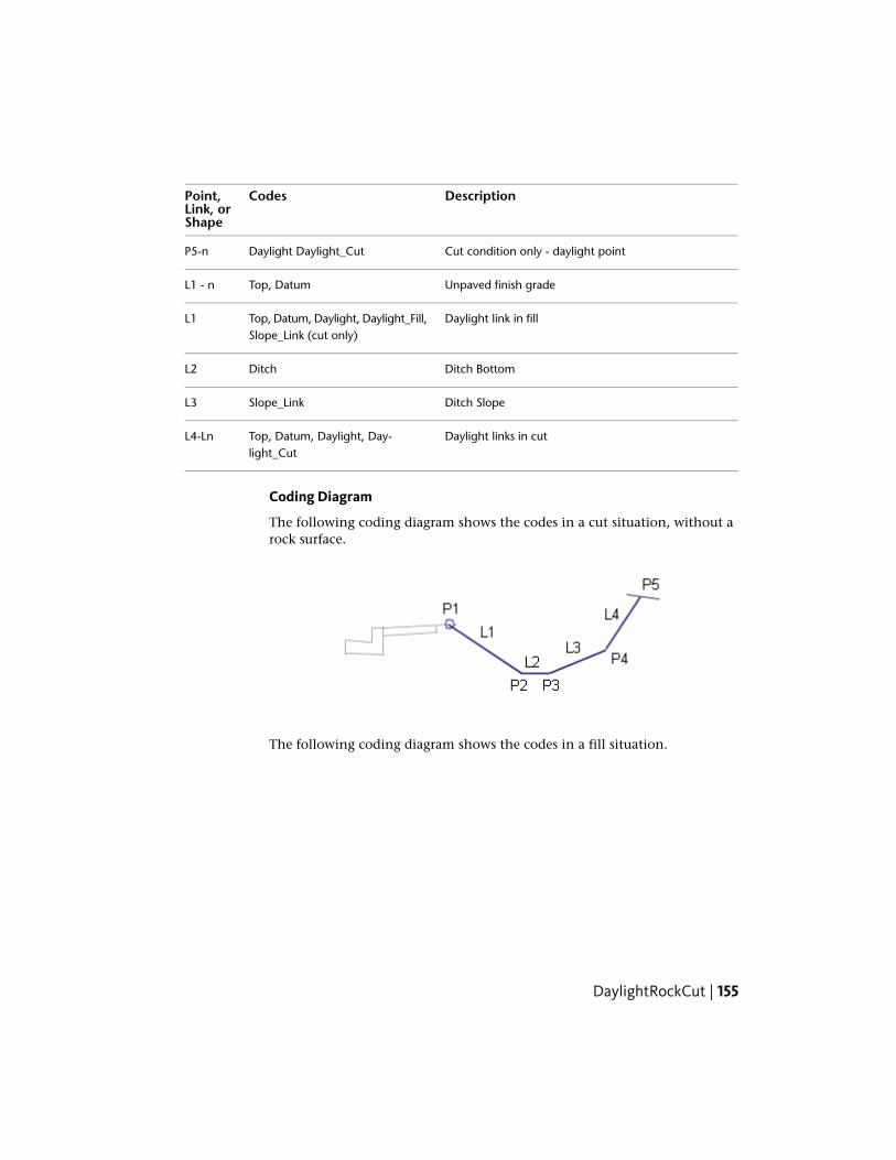
DescriptionCodesPoint,Link, orShape
Cut condition only - daylight pointDaylight Daylight_CutP5-n
Unpaved finish gradeTop, DatumL1 - n
Daylight link in fillTop, Datum, Daylight, Daylight_Fill,Slope_Link (cut only)
L1
Ditch BottomDitchL2
Ditch SlopeSlope_LinkL3
Daylight links in cutTop, Datum, Daylight, Day-light_Cut
L4-Ln
Coding Diagram
The following coding diagram shows the codes in a cut situation, without arock surface.
The following coding diagram shows the codes in a fill situation.
DaylightRockCut | 155

The following coding diagram shows the codes in a cut situation, with a rocksurface.
DaylightStandardThis subassembly creates corridor-side daylighting links with user-definedslope configurations, such as flat, medium, and maximum slopes for cut andfill situations.
This subassembly creates either a v-shaped or flat- bottom ditch in cutsituations, and includes an option to include guardrail widening for steep fillconditions.
The final daylighting link can be omitted for cases where the corridor modelneeds to be left in an incomplete state. For example, this might be done so
156 | Chapter 1 Subassembly Reference

that grading surfaces on adjacent properties can tie to the hinge point on theuncompleted roadway.
DaylightStandard | 157

You can also specify optional lined materials for daylight and other links (AllLinks, Daylight Links, Fill Links Only, and None).
Attachment
This subassembly is typically attached to the subassembly used at the outsideedge of the roadway, such as the edge of shoulder, back of sidewalk, or backof curb. The attachment point is at the inside edge of the ditch front link, thetop of the flat or medium fill slope, or inside edge of guardrail widening link,depending on conditions.
Input ParametersNote: All dimensions are in meters or feet unless otherwise noted. All slopesare in run-over-rise form (for example, 4 : 1) unless indicated as a percentslope with a “%” sign.
DefaultTypeDescriptionParameter
RightLeft / RightSpecifies which side to place thesubassembly
Side
IncludeInclude / OmitInclude or omit the Daylight link.Include Daylight LinkOmit Daylight Link
6 ( : 1)Numeric, posit-ive
First, flattest, catch slope to at-tempt. (x : 1)
Flat Cut Slope
158 | Chapter 1 Subassembly Reference

DefaultTypeDescriptionParameter
1.5 mNumericMaximum allowable height of theclosing link using the Flat CutSlope
Flat Cut Max Height5 ft
4 ( : 1)Numeric, posit-ive
Cut slope to attempt if the FlatCut Slope link exceeds the FlatCut Max Height
Medium Cut Slope
3 mNumericMaximum allowable height of theclosing link using the MediumCut Slope
Medium Cut Max Height10 ft
2 ( : 1)Numeric, posit-ive
Cut slope to use if the MediumCut Slope link exceeds the Medi-um Cut Max Height
Steep Cut Slope
3.6 mNumericFor cut sections, the width of thefront-of-ditch link
Foreslope Width12 ft
4 ( : 1)Numeric, posit-ive
Slope of the front-of-ditch link (x: 1). This link is always inserteddownwards.
Foreslope Slope
1 mNumeric, posit-ive
Width of the bottom of ditch. Usezero for a V-ditch.
Ditch Width3 ft
6 ( : 1)Numeric, posit-ive
First, flattest, catch slope to at-tempt. (x : 1)
Flat Fill Slope
1.5 mNumericMaximum allowable height of theclosing link using the Flat FillSlope
Flat Fill Max Height5 ft
4 ( : 1)Numeric, posit-ive
Fill slope to attempt if the Flat FillSlope link exceeds the Flat FillMax Height
Medium Fill Slope
3 mNumericMaximum allowable height of theclosing link using the Medium FillSlope
Medium Fill Max Height10 ft
DaylightStandard | 159

DefaultTypeDescriptionParameter
2 ( : 1)Numeric, posit-ive
Fill slope to use if the Medium FillSlope link exceeds the MediumFill Max Height
Steep Fill Slope
0.6 mNumeric, posit-ive
Width of the guardrail wideninglink for fill slopes using Steep Fill
Guardrail Width2 ft
Slope. Use zero for no guardrailwidening.
-2 (%)Numeric% slope of the guardrail wideninglink
Guardrail %Slope
OmitInclude / OmitInclude to insert the guardrailstructure when guardrail widen-
Include GuardrailOmit Guardrail
ing occurs. Omit does not insertthe guardrail structure.
0.3 mNumericWhen the guardrail is included,the width from the attachment
Width to Post1 ft
point to the inside edge of theguardrail post.
NoneStringSpecifies to round off the daylightlink at the catch point
Rounding Option
LengthStringSpecifies what parameter is usedfor rounding
Rounding By
1.500 ftNumeric, posit-ive
Specifies value for length or radiusRounding Parameter
6Numeric, posit-ive
Specifies number of intermittentpoints on rounding links (maxim-um 10 links)
Rounding Tesselation
NoneStringSpecifies to place optional mater-ial lining along daylight links. You
Place Lined Material
can choose All Links, DaylightLinks, Fill Links Only, and None.
160 | Chapter 1 Subassembly Reference

DefaultTypeDescriptionParameter
1 : 1SlopeSpecifies the slope limit untilwhich the associated material lin-ing is placed
Slope Limit 1
12 inchesNumeric, posit-ive
Specifies the thickness of linedmaterial. This thickness is meas-ured perpendicular to the link.
Material 1 Thickness
Rip RapStringSpecifies the name of the materialapplies for lining along gradinglinks
Material 1 Name
2 : 1SlopeSpecifies the slope limit untilwhich the associated material lin-ing is placed
Slope Limit 2
6 inchesNumeric, posit-ive
Specifies the thickness of linedmaterial. This thickness is meas-ured perpendicular to the link.
Material 2 Thickness
Rip RapStringSpecifies the name of the materialapplies for lining along gradinglinks
Material 2 Name
4 : 1SlopeSpecifies the slope limit untilwhich the associated material lin-ing is placed
Slope Limit 3
4 inchesNumeric, posit-ive
Specifies the thickness of linedmaterial. This thickness is meas-ured perpendicular to the link.
Material 3 Thickness
Seeded GrassStringSpecifies the name of the materialapplies for lining along gradinglinks
Material 3 Name
DaylightStandard | 161

Target ParametersThis section lists the parameters in this subassembly that can be mapped toone or more target objects. For more information, see Setting Targets in theAutoCAD Civil 3D User’s Guide Help.
StatusDescriptionParameter
RequiredName of the daylighting surface. The following ob-ject types can be used as targets for specifying thesurface: surfaces.
Daylight Surface
Output Parameters
TypeDescriptionParameter
NumericOffset of the daylight pointDaylight Offset
NumericElevation of the daylight pointDaylight Elevation
Behavior
The following steps are used by this subassembly to determine whichconditions apply:
1 The location of the Cut Test Point (see diagram) is calculated using theForeslope Width, Foreslope Slope, and Ditch Width parameters.
2 If any portion of the foreslope slope or ditch bottom is in cut, the sectionis computed as a cut section as follows:
■ If the Cut Test Point is above the target surface, the Foreslope link orditch bottom is truncated at the point where it intersects the surfacegoing from cut to fill, otherwise:
■
■ If Include Daylight Link is set to omit, no daylight link is calculated.
162 | Chapter 1 Subassembly Reference

■ The intercept to the target surface is calculated using the Flat CutSlope value.
■ If the height of the flat cut slope exceeds the Flat Cut Max Height,the intercept to the target surface is re-calculated using the MediumCut Slope value.
■ If the height of the medium cut slope exceeds the Medium Cut MaxHeight, the intercept to the target surface is re-calculated using theSteep Cut Slope value.
3 If no portion of the foreslope link or ditch bottom is below the targetsurface, the section is computed as a Fill section as follows:
■ The intercept to the target surface is calculated using the Flat Fill Slopevalue.
■ If the height of the flat fill slope exceeds the Flat Fill Max Height, theintercept to the target surface is re-calculated using the Medium FillSlope value.
■ If the height of the medium fill slope exceeds the Medium Fill MaxHeight, the guardrail widening link is added to the assembly usingthe Guardrail Width and Guardrail %Slope parameters (unless theGuardrail Width is zero). The intercept to the target surface isre-calculated from the outside edge of the guardrail widening linkusing the Steep Fill Slope value.
■ If Include Daylight Link is True, the flat, medium, or steep fill slopelink is added to the assembly.
A guardrail structure may be applied to fill sections that meet the criteria forusing the steep fill slope. If this criteria is met, the Guardrail Width is not zero,and Include Guardrail is set to true, then a guardrail structure is drawn at thestation. The dimensions of the guardrail structure are fixed as shown in thediagram below.
DaylightStandard | 163

Like other daylight subassemblies, this subassembly optionally lets you adda lined material. You can specify three ranges of slopes. Material type 1 isapplied if the slope of the links is up to the specified slope value. From slope1 to slope 2, the second type of material applied. Similarly, if the slopes oflinks fall within slope 2 and slope 3 values, then material 3 is applied. If thelink slopes are flatter than slope limit 3, then no material is applied.
If a lined material is added to the subassembly, then parallel links are addedto the daylight links with specified thickness. This thickness parameter (forexample, Material 1 Thickness) is measured perpendicular to the link. Bottomlevel links are coded with Datum and daylight links are coded with Top. Shapesenclosed by these materials are coded with material name.
NOTE In Civil 3D 2010 and previous versions, the Material Thickness parameterwas measured vertically. In Civil 3D 2011 and later, this parameter is measuredperpendicular to the link. Therefore, if you open a drawing containing thesesubassemblies that was created in Civil 3D 2010 or prior in Civil 3D 2011 or later,and then rebuild the corridor(s), this parameter will be changed to reflect the newbehavior. Any volume reports that use this subassembly will be updated to reflectthe new behavior.
Layout Mode Operation
In layout mode, this subassembly shows both the cut and fill flat-slopeconditions. The daylight links are extended outward for a horizontal distanceof 3 meters or 10 feet, and are shown in dashed lines terminating in arrowheadspointing outwards.
164 | Chapter 1 Subassembly Reference

Point, Link, and Shape CodesThe following table lists the point, link, and shape codes for this subassemblythat have codes assigned to them. Point, link, or shape codes for thissubassembly that do not have codes assigned are not included in this table.
DescriptionCodePoint, Link, or Shape
Hinge point for the normal fill conditionHingeP1Hinge_Fill
Hinge point for the fill condition withguardrail widening
HingeHinge_Fill
P2
Inside edge of the bottom of the ditch (cutcondition only)
Ditch_InP2
Outside edge of the bottom of the ditch(cut condition only)
Ditch_OutHinge
P3
Hinge_Cut
Fill slope stake point (fill condition only)DaylightP3Daylight_Fill
Cut slope stake point (cut condition only)DaylightP4Daylight_Cut
All links added by this subassembly, exceptfor the guardrail structure links.
TopDatum
All Links
No codes are assigned to the points on theguardrail structure, if included.
NoneGuardrail points
All links comprising the guardrail structure,if included.
GuardrailGuardrail links
Daylight link for cut sectionTopL3
DaylightStandard | 165

DescriptionCodePoint, Link, or Shape
DatumDaylightDaylight_Cut
Daylight link for fill sectionTopFill Daylight LinkDatumDaylightDaylight_Fill
Coding Diagram
DaylightToOffsetThis subassembly inserts a daylight link from the attachment point to a givenoffset from the baseline.
166 | Chapter 1 Subassembly Reference

You can also specify optional lined materials for daylight and other links (AllLinks, Daylight Links, Fill Links Only, and None).
Attachment
The attachment point is at the inside edge of the daylight link.
Input ParametersNote: All dimensions are in meters or feet unless otherwise noted.
DefaultTypeDescriptionParameter
3.0 mNumeric+/- offset of the daylight point from thebaseline. Specifying a positive value for the
Daylight Offset fromBaseline 10.0 ft
this parameter inserts this subassembly onthe right side of a corridor, or controllingbaseline. A negative value inserts it on theleft side. For more information, see "Insert-ing Subassemblies on Right and Left Sidesof a Corridor" in the Corridors chapter ofthe AutoCAD Civil 3D User's Guide Help.
NoneStringSpecifies to round off the daylight link atthe catch point
Rounding Option
LengthStringSpecifies what parameter is used forrounding
Rounding By
1.500 ftNumeric, pos-itive
Specifies value for length or radiusRounding Parameter
6Numeric, pos-itive
Specifies number of intermittent points onrounding links (maximum 10 links)
Rounding Tesselation
DaylightToOffset | 167

DefaultTypeDescriptionParameter
NoneStringSpecifies to place optional material liningalong daylight links. You can choose All
Place Lined Material
Links, Daylight Links, Fill Links Only, andNone.
1 : 1SlopeSpecifies the slope limit until which the as-sociated material lining is placed
Slope Limit 1
12inches
Numeric, pos-itive
Specifies the thickness of lined material.This thickness is measured perpendicularto the link.
Material 1 Thickness
Rip RapStringSpecifies the name of the material appliesfor lining along grading links
Material 1 Name
2 : 1SlopeSpecifies the slope limit until which the as-sociated material lining is placed
Slope Limit 2
6 inchesNumeric, pos-itive
Specifies the thickness of lined material.This thickness is measured perpendicularto the link.
Material 2 Thickness
Rip RapStringSpecifies the name of the material appliesfor lining along grading links
Material 2 Name
4 : 1SlopeSpecifies the slope limit until which the as-sociated material lining is placed
Slope Limit 3
4 inchesNumeric, pos-itive
Specifies the thickness of lined material.This thickness is measured perpendicularto the link.
Material 3 Thickness
SeededGrass
StringSpecifies the name of the material appliesfor lining along grading links
Material 3 Name
168 | Chapter 1 Subassembly Reference

Target ParametersThis section lists the parameters in this subassembly that can be mapped toone or more target objects. For more information, see Setting Targets in theAutoCAD Civil 3D User’s Guide Help.
StatusDescriptionParameter
OptionalMay be used to override the fixed Daylight Offset andtie the daylight offset to an offset alignment. The follow-
Daylight Offset
ing object types can be used as targets for specifyingthe offset: alignments, polylines, feature lines, or surveyfigures.
RequiredName of the daylighting surface. The following objecttypes can be used as targets for specifying the surface:surfaces.
Daylight Surface
Output Parameters
TypeDescriptionParameter
NumericOffset of the daylight pointDaylight Offset
NumericElevation of the daylight pointDaylight Elevation
Behavior
A daylight ink is inserted from the attachment point to the surface at thegiven offset.
Like other daylight subassemblies, this subassembly optionally lets you adda lined material. You can specify three ranges of slopes. Material type 1 isapplied if the slope of the links is up to the specified slope value. From slope1 to slope 2, the second type of material applied. Similarly, if the slopes oflinks fall within slope 2 and slope 3 values, then material 3 is applied. If thelink slopes are flatter than slope limit 3, then no material is applied.
If a lined material is added to the subassembly, then parallel links are addedto the daylight links with specified thickness. This thickness parameter (forexample, Material 1 Thickness) is measured perpendicular to the link. Bottomlevel links are coded with Datum and daylight links are coded with Top. Shapesenclosed by these materials are coded with material name.
DaylightToOffset | 169

NOTE In Civil 3D 2010 and previous versions, the Material Thickness parameterwas measured vertically. In Civil 3D 2011 and later, this parameter is measuredperpendicular to the link. Therefore, if you open a drawing containing thesesubassemblies that was created in Civil 3D 2010 or prior in Civil 3D 2011 or later,and then rebuild the corridor(s), this parameter will be changed to reflect the newbehavior. Any volume reports that use this subassembly will be updated to reflectthe new behavior.
Layout Mode Operation
In layout mode, this subassembly displays a link extending outwards at a -4: 1 slope to the specified offset. The daylight link terminates with an arrowheadpointing outwards.
Point, Link, and Shape CodesThe following table lists the point, link, and shape codes for this subassemblythat have codes assigned to them. Point, link, or shape codes for thissubassembly that do not have codes assigned are not included in this table.
DescriptionCodePoint, Link, or Shape
Hinge point. Hinge_Cut is used if the daylight linkhas an upward slope; Hinge_Fill is used if the daylightlink has a downward slope.
HingeHinge_Cut orHinge_Fill
P1
Daylight pointDaylightP2Daylight_Cut orDaylight_Fill
Daylight link for cut sectionTopL1DatumDaylightDaylight_Cut
170 | Chapter 1 Subassembly Reference

DescriptionCodePoint, Link, or Shape
Daylight link for fill sectionTopL1DatumDaylightDaylight_Fill
Coding Diagram
DaylightToROWThis subassembly inserts a daylight link from the attachment point to a givenoffset from the right-of-way limit on a target surface.
You can also specify optional lined materials for daylight and other links (AllLinks, Daylight Links, Fill Links Only, and None).
Attachment
The attachment point is at the inside edge of the daylight link.
DaylightToROW | 171

Input ParametersNote: All dimensions are in meters or feet unless otherwise noted.
DefaultTypeDescriptionParameter
3.0 mNumeric+/- offset of the right-of-way limit fromthe baseline. Specifying a positive value
ROW Offset from Baseline10.0 ft
for the this parameter inserts this sub-assembly on the right side of a corridor,or controlling baseline. A negative valueinserts it on the left side. For more inform-ation, see "Inserting Subassemblies onRight and Left Sides of a Corridor" in theCorridors chapter of the AutoCAD Civil3D User's Guide Help.
0.0Numeric+/- value added to the ROW Limit Offset.A negative adjustment value moves the
Offset Adjustment
daylight point inside of the ROW limit;a positive value moves it outside theROW limit.
NoneStringSpecifies to round off the daylight link atthe catch point
Rounding Option
LengthStringSpecifies what parameter is used forrounding
Rounding By
1.500 ftNumeric, posit-ive
Specifies value for length or radiusRounding Parameter
6Numeric, posit-ive
Specifies number of intermittent pointson rounding links (maximum 10 links)
Rounding Tesselation
NoneStringSpecifies to place optional material liningalong daylight links. You can choose All
Place Lined Material
Links, Daylight Links, Fill Links Only, andNone.
1 : 1SlopeSpecifies the slope limit until which theassociated material lining is placed
Slope Limit 1
172 | Chapter 1 Subassembly Reference

DefaultTypeDescriptionParameter
12 inchesNumeric, posit-ive
Specifies the thickness of lined material.This thickness is measured perpendicularto the link.
Material 1 Thickness
Rip RapStringSpecifies the name of the material appliesfor lining along grading links
Material 1 Name
2 : 1SlopeSpecifies the slope limit until which theassociated material lining is placed
Slope Limit 2
6 inchesNumeric, posit-ive
Specifies the thickness of lined material.This thickness is measured perpendicularto the link.
Material 2 Thickness
Rip RapStringSpecifies the name of the material appliesfor lining along grading links
Material 2 Name
4 : 1SlopeSpecifies the slope limit until which theassociated material lining is placed
Slope Limit 3
4 inchesNumeric, posit-ive
Specifies the thickness of lined material.This thickness is measured perpendicularto the link.
Material 3 Thickness
SeededGrass
StringSpecifies the name of the material appliesfor lining along grading links
Material 3 Name
Target ParametersThis section lists the parameters in this subassembly that can be mapped toone or more target objects. For more information, see Setting Targets in theAutoCAD Civil 3D User’s Guide Help.
StatusDescriptionParameter
OptionalMay be used to override the fixed ROW Offset andtie the ROW offset to an offset alignment. The follow-
ROW Offset
ing object types can be used as targets for specifyingthe offset: alignments, polylines, feature lines, orsurvey figures.
DaylightToROW | 173
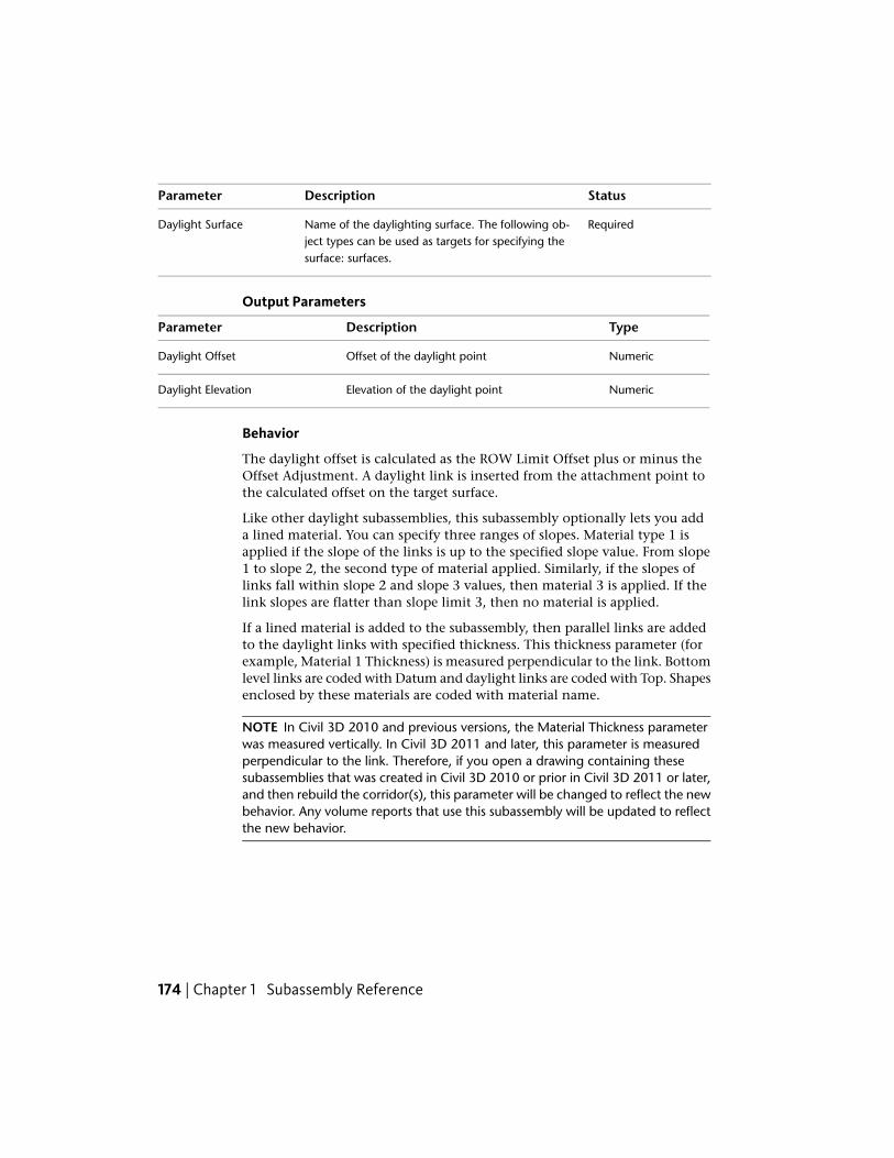
StatusDescriptionParameter
RequiredName of the daylighting surface. The following ob-ject types can be used as targets for specifying thesurface: surfaces.
Daylight Surface
Output Parameters
TypeDescriptionParameter
NumericOffset of the daylight pointDaylight Offset
NumericElevation of the daylight pointDaylight Elevation
Behavior
The daylight offset is calculated as the ROW Limit Offset plus or minus theOffset Adjustment. A daylight link is inserted from the attachment point tothe calculated offset on the target surface.
Like other daylight subassemblies, this subassembly optionally lets you adda lined material. You can specify three ranges of slopes. Material type 1 isapplied if the slope of the links is up to the specified slope value. From slope1 to slope 2, the second type of material applied. Similarly, if the slopes oflinks fall within slope 2 and slope 3 values, then material 3 is applied. If thelink slopes are flatter than slope limit 3, then no material is applied.
If a lined material is added to the subassembly, then parallel links are addedto the daylight links with specified thickness. This thickness parameter (forexample, Material 1 Thickness) is measured perpendicular to the link. Bottomlevel links are coded with Datum and daylight links are coded with Top. Shapesenclosed by these materials are coded with material name.
NOTE In Civil 3D 2010 and previous versions, the Material Thickness parameterwas measured vertically. In Civil 3D 2011 and later, this parameter is measuredperpendicular to the link. Therefore, if you open a drawing containing thesesubassemblies that was created in Civil 3D 2010 or prior in Civil 3D 2011 or later,and then rebuild the corridor(s), this parameter will be changed to reflect the newbehavior. Any volume reports that use this subassembly will be updated to reflectthe new behavior.
174 | Chapter 1 Subassembly Reference
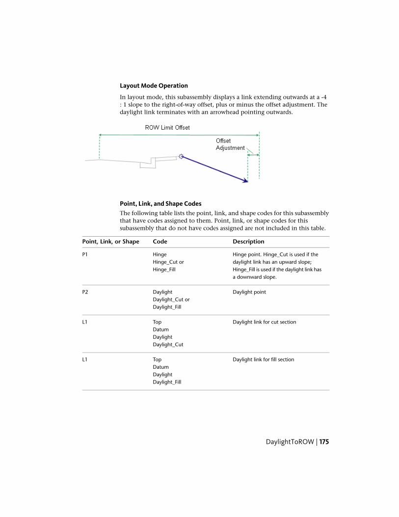
Layout Mode Operation
In layout mode, this subassembly displays a link extending outwards at a -4: 1 slope to the right-of-way offset, plus or minus the offset adjustment. Thedaylight link terminates with an arrowhead pointing outwards.
Point, Link, and Shape CodesThe following table lists the point, link, and shape codes for this subassemblythat have codes assigned to them. Point, link, or shape codes for thissubassembly that do not have codes assigned are not included in this table.
DescriptionCodePoint, Link, or Shape
Hinge point. Hinge_Cut is used if thedaylight link has an upward slope;
HingeHinge_Cut or
P1
Hinge_Fill is used if the daylight link hasa downward slope.
Hinge_Fill
Daylight pointDaylightP2Daylight_Cut orDaylight_Fill
Daylight link for cut sectionTopL1DatumDaylightDaylight_Cut
Daylight link for fill sectionTopL1DatumDaylightDaylight_Fill
DaylightToROW | 175

Coding Diagram
DitchThis subassembly inserts a flat or V-shaped ditch with user-defined horizontaland vertical control parameters.
This subassembly can also include an optional lining material.
Attachment
The attachment point is at the inside edge of the first link. This will be eitherthe inner buffer or the foreslope link of the ditch if the inner buffer width iszero. This is typically connected to the outside edge of a shoulder.
176 | Chapter 1 Subassembly Reference

Input ParametersNote: All dimensions are in meters or feet unless otherwise noted. All slopesare in run-over-rise form (for example, 4 : 1) unless indicated as a percentslope with a “%” sign.
DefaultTypeDescriptionParameter
RightLeft/RightSpecifies side to insert subassemblySide
Cut/FillSelection list: a)Cut/Fill, b)Cut, c) FIll
Specifies to use the ditch in cut andfill, fill only or cut only
Include Ditch
1 mNumeric, positiveWidth of the bottom of ditch. Usezero for a V-shaped ditch.
Ditch Width3 ft
1 mNumeric, positiveDepth of DitchDitch Depth3 ft
4 ( : 1)Numeric, positiveSlope of the front-of-ditch link (x :1). This link is always inserteddownwards.
Foreslope Slope
1 mNumeric, positiveAllows a Buffer to be placed beforethe Foreslope (zero to omit)
Foreslope BufferWidth 3 ft
-6 (:1)Numeric, positiveSlope of the foreslope bufferForeslope BufferSlope
4 ( : 1)Numeric, positiveSlope of the back-of-ditch link (x :1). This link is always inserted up-wards.
Backslope Slope
1 mNumeric, positiveAllows a Buffer to be placed back-slope the backslope (zero to omit)
Backslope Buffer3 ft
6 (:1)Numeric, positiveSlope of the backslope bufferBackslope BufferSlope
NoneStringSpecifies to place optional materiallining along daylight links. You canchoose All Links or None.
Place Lined Mater-ial
Ditch | 177

DefaultTypeDescriptionParameter
1 : 1SlopeSpecifies the slope limit until whichthe associated material lining isplaced
Slope Limit 1
12 inchesNumeric, positiveSpecifies the thickness of lined ma-terial. This thickness is measured
Material 1 Thick-ness
perpendicular to the side of theslope.
Rip RapStringSpecifies the name of the materialapplies for lining along grading links
Material 1 Name
2 : 1SlopeSpecifies the slope limit until whichthe associated material lining isplaced
Slope Limit 2
6 inchesNumeric, positiveSpecifies the thickness of lined ma-terial. This thickness is measured
Material 2 Thick-ness
perpendicular to the side of theslope.
Rip RapStringSpecifies the name of the materialapplies for lining along grading links
Material 2 Name
4 : 1SlopeSpecifies the slope limit until whichthe associated material lining isplaced
Slope Limit 3
4 inchesNumeric, positiveSpecifies the thickness of lined ma-terial. This thickness is measured
Material 3 Thick-ness
perpendicular to the side of theslope.
Seeded GrassStringSpecifies the name of the materialapplies for lining along grading links
Material 3 Name
Target ParametersThis section lists the parameters in this subassembly that can be mapped toone or more target objects, such as a surface, alignment, or profile object in
178 | Chapter 1 Subassembly Reference

a drawing. For more information, see Setting Targets in the AutoCAD Civil3D User’s Guide Help.
StatusDescriptionParameter
OptionalMay be used to override the fixed width of theforeslope buffer. The following object types can be
Ditch Inner EdgeAlignment
used as targets for specifying this: alignments, poly-lines, feature lines, or survey figures.
OptionalMay be used to override the fixed width of thebackslope buffer. The following object types can be
Ditch outer edgeAlignment
used as targets for specifying this: alignments, poly-lines, feature lines, or survey figures.
OptionalMay be used to override the fixed foreslope andbackslope widths. The following object types can be
Ditch Bottom Profile
used as targets for specifying this elevation: profiles,3D polylines, feature lines, or survey figures.
OptionalSurface used to determine if the ditch is in cut or fill.The following object types can be used as targets forspecifying this surface: surfaces.
Target Surface
Output Parameters
None.
Behavior
This subassembly will insert a simple ditch shape (either flat bottom orV-shaped ditch) with optional foreslope and backslope buffers. The locationof the inner ditch edge can be specified with a fixed width, or with an optionalalignment. The ditch depth can be specified with a fixed height, or a profilecan be assigned to control the depth. The Cut/Fill Test point is P3. Dependingon the Include Ditch input parameter, the ditch will only be placed in cut,fill, or both cut and fill.
Ditch | 179

NOTE In Civil 3D 2010 and previous versions, the Material Thickness parameterwas measured vertically. In Civil 3D 2011 and later, this parameter is measuredperpendicular to the link. Therefore, if you open a drawing containing thesesubassemblies that was created in Civil 3D 2010 or prior in Civil 3D 2011 or later,and then rebuild the corridor(s), this parameter will be changed to reflect the newbehavior. Any volume reports that use this subassembly will be updated to reflectthe new behavior.
Layout Mode Operation
In layout mode, this subassembly displays all of the links comprising the ditchwith the parameters set as input by the user.
Point, Link, and Shape CodesThe following table lists the point, link, and shape codes for this subassemblythat have codes assigned to them. Point, link, or shape codes for thissubassembly that do not have codes assigned are not included in this table.
DescriptionCodesPoint, Link, orShape
HingeP2
Inside bottom of ditchDitch_InP3
Outside bottom of ditchDitch_OutP4
HingeP5
Top DatumL1-5
Slope_LinkL2,L4
Ditch BottomDitchL3
180 | Chapter 1 Subassembly Reference
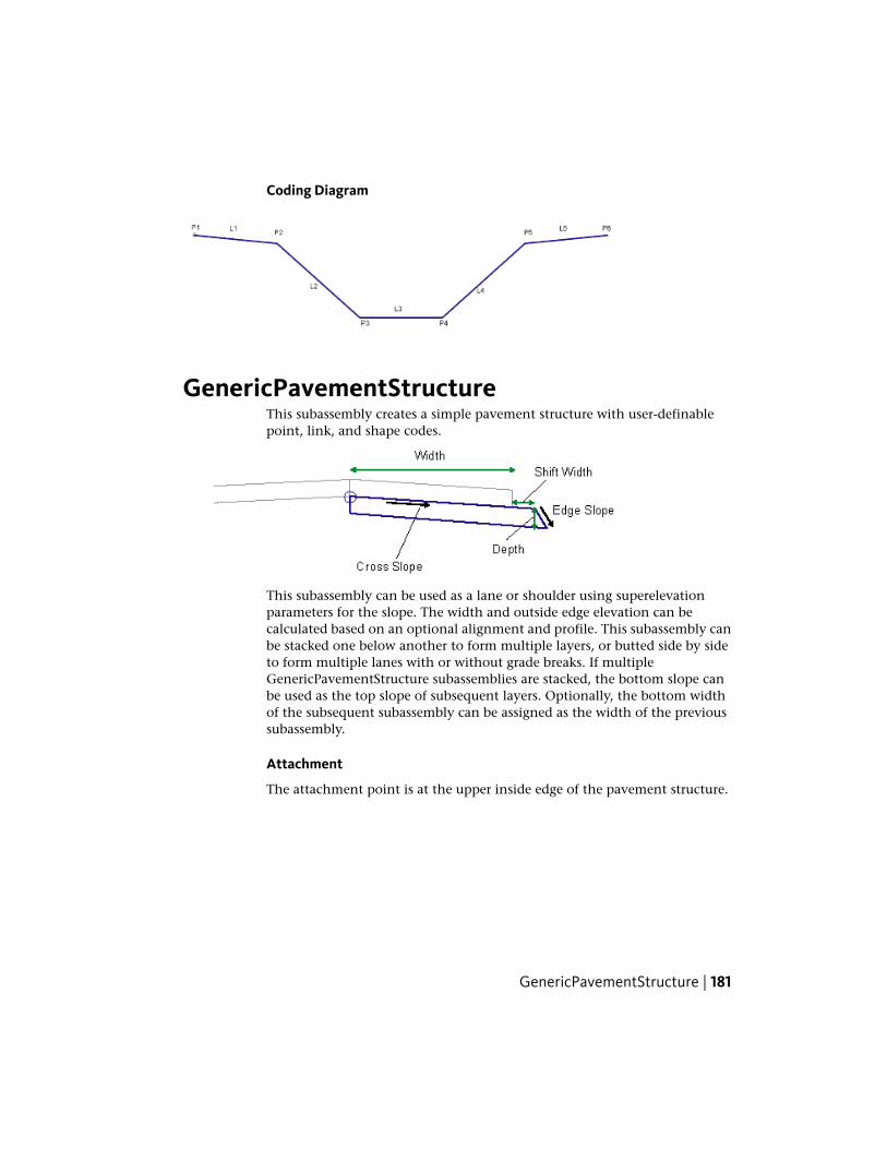
Coding Diagram
GenericPavementStructureThis subassembly creates a simple pavement structure with user-definablepoint, link, and shape codes.
This subassembly can be used as a lane or shoulder using superelevationparameters for the slope. The width and outside edge elevation can becalculated based on an optional alignment and profile. This subassembly canbe stacked one below another to form multiple layers, or butted side by sideto form multiple lanes with or without grade breaks. If multipleGenericPavementStructure subassemblies are stacked, the bottom slope canbe used as the top slope of subsequent layers. Optionally, the bottom widthof the subsequent subassembly can be assigned as the width of the previoussubassembly.
Attachment
The attachment point is at the upper inside edge of the pavement structure.
GenericPavementStructure | 181

Input Parameters
Note: All dimensions are in meters or feet unless otherwise noted. All slopesare in run-over-rise form (for example, 4 : 1), unless indicated as a percentslope with a “%” sign.
DefaultTypeDescriptionParameter
RightLeft / RightIndicates which side the sub-assembly is inserted towards.
Side
3.6 m 12.0 ftNumeric, positiveWidth of the subassembly.Width
0.2 m 0.67 ftNumeric, positiveSpecifies optional additional widthto add.
Shift Width
-2%NumericDefault slope of the top link, whensuperelevation slope for the align-ment is not specified.
Default CrossSlope
NoList of options: No, Outsidelane slope, Inside lane slope,
Specifies to use slope from superel-evation specification defined on thebaseline alignment.
Use Supereleva-tion Slope
Outside shoulder slope, In-side shoulder slope
0.2 m 0.67 ftNumeric, positiveDepth from top link to the bottomlink of the subassembly.
Depth
NoBoolean Yes/NoIndicates to deflect outside verticalface to a specified slope.
Deflect OuterVertical Face
1:1NumericSpecifies the slope of the outeredge if choose not to be vertical.
Outer Edge Slope
StringSpecifies point codes to the insidepoint on the top link.
Inside-Top PointCodes
StringSpecifies point codes to the outsidepoint on the top link.
Outside-TopPoint Codes
StringSpecifies point codes to the outsidepoint on the bottom link.
Outside-BottomPoint Codes
182 | Chapter 1 Subassembly Reference

DefaultTypeDescriptionParameter
StringSpecifies point codes to the insidepoint on the bottom link.
Inside-BottomPoint Codes
StringSpecifies codes to the top link.Top Link Codes
StringSpecifies codes to the bottom link.Bottom LinkCodes
StringSpecifies codes to the right link.Right Link Codes
StringSpecifies codes to the left link.Left Link Codes
StringSpecifies codes for the enclosedshape of the structure.
Shape Codes
Target ParametersThis section lists the parameters in this subassembly that can be mapped toone or more target objects. For more information, see Setting Targets in theAutoCAD Civil 3D User’s Guide Help.
StatusDescriptionParameter
OptionalMay be used to override the fixed width and tie the pointon the top link which defines “width” to an offset align-
Width
ment. The following object types can be used as targetsfor specifying the width: alignments, polylines, featurelines, or survey figures.
OptionalMay be used to override the fixed slope and tie the pointon the top link which defines “width” to an offset profile.
Edge Elevation
The following object types can be used as targets for spe-cifying the elevation: profiles, 3D polylines, feature lines,or survey figures.
Output Parameters
TypeDescriptionParameter
Left / RightIndicates which side the subassembly is in-serted towards.
Side
GenericPavementStructure | 183

TypeDescriptionParameter
Numeric, positiveTotal width of the top link including the ef-fective shift width.
Top Width
Numeric, positiveTotal bottom width of the pavement struc-ture including the shift width and width dueto the deflected outer face.
Bottom Width
Numeric, positiveDepth from top link to the bottomDepth
NumericCross slope of the structure.Cross Slope
Behavior
This subassembly builds a skeletal subassembly that lets you specify variousparameters. All point, link, and shape codes can be user-defined as needed.Additionally, this subassembly can get slopes from a target parameter (profile),or from the superelevation specified on the alignment. It can also assign thewidth from an offset alignment.
While defining an assembly, you can assign the width of the previoussubassembly (the one above), plus a shift width to the subassembly, so thatstepped layers are possible.
Layout Mode Operation
In layout mode, the subassembly draws the lane using the input parametervalues.
Point, Link, and Shape Codes
None.
Coding Diagram
184 | Chapter 1 Subassembly Reference

LaneBrokenBackThis subassembly creates a cross-sectional representation of travel lanes for abroken-back roadway, where the inside and outside lanes have differentdownward slopes.
This subassembly is used for the inside lanes on divided, broken-back highways.The pavement structure follows the standards described in “Pavement Structureon Paved Sections” in the AutoCAD Civil 3D User’s Guide Help.
Attachment
The attachment point is at the inside edge of lane on the finish grade surface.This component can be attached to either the left or right side.
Input ParametersNote: All dimensions are in meters or feet unless otherwise noted. All slopesare in run-over-rise form (for example, 4 : 1) unless indicated as a percentslope with a “%” sign.
DefaultTypeDescriptionParameter
RightLeft / RightSpecifies which side to placethe subassembly
Side
NoYes / NoSpecifies that inside edge oftravelway to be coded asCrown
Crown Point on Inside
3.6 mNumeric, positiveWidth of the inside lanesInside Width12.0 ft
- 2.0 (%)NumericDefault % Slope of the insidelanes to be used if the superel-
Inside Default %Slope
LaneBrokenBack | 185

DefaultTypeDescriptionParameter
evation for the alignment isnot defined
3.6 mNumeric, positiveWidth of the outside lanesOutside Width12.0 ft
- 2.5 (%)NumericDefault % Slope of the out-side lanes to be used if the
Outside Default %Slope
superelevation for the align-ment is not defined
0.025 mNumeric, non-negativeThickness of the Pave1 layer(zero to omit)
Pave1 Depth0.083 ft
0.025 mNumeric, non-negativeThickness of the Pave2 layer(zero to omit)
Pave2 Depth0.083 ft
0.100 mNumeric, non-negativeThickness of the Base layerBase Depth0.333 ft(zero to omit)
0.300 mNumeric, non-negativeThickness of the Subbase layer(zero to omit)
Subbase Depth1.0 ft
Target ParametersThis section lists the parameters in this subassembly that can be mapped toone or more target objects. For more information, see Setting Targets in theAutoCAD Civil 3D User’s Guide Help.
StatusDescriptionParameter
OptionalMay be used to override the fixed Inside Width and tiethe edge-of-inside-lane to an offset alignment. The
Inside Width
following object types can be used as targets for spe-cifying the width: alignments, polylines, feature lines,or survey figures.
OptionalMay be used to override the fixed Outside Width andtie the edge-of-outside-lane to an offset alignment. The
Outside Width
following object types can be used as targets for spe-cifying the width: alignments, polylines, feature lines,or survey figures.
186 | Chapter 1 Subassembly Reference

StatusDescriptionParameter
OptionalMay be used to override the normal slope and tie theelevation of the edge-of-inside-lane to the elevation of
Inside Elevation
a profile. The following object types can be used astargets for specifying the elevation: profiles, 3D poly-lines, feature lines, or survey figures.
OptionalMay be used to override the normal slope and tie theelevation of the edge-of-outside-lane to the elevation
Outside Elevation
of a profile. The following object types can be used astargets for specifying the elevation: profiles, 3D poly-lines, feature lines, or survey figures.
Output Parameters
TypeDescriptionParameter
NumericWidth of the inside laneInside Lane Width
Numeric% slope of the inside laneInside %Slope
NumericWidth of the outside laneOutside Lane Width
Numeric% slope of the outside laneOutside %Slope
Behavior
This subassembly creates a set of inside lanes and outside lanes that may havedifferent slopes. The inside lanes are inserted outwards from the attachmentpoint using the Inside Lane superelevation slope. If the superelevation is notdefined at a station, the Inside Default %Slope value is used. The outside lanesare inserted outward from the end of the inside lanes, using the outside lanesuperelevation slope, or the Outside Default %Slope.
If an offset horizontal alignment name is assigned to the Width during corridormodeling, the width of the lane will vary to match the offset of the alignment.
Layout Mode Operation
In layout mode, this subassembly displays the finish, base, and subbase linksfor the given widths and depths at the default % slopes.
LaneBrokenBack | 187

Point, Link, and Shape CodesThe following table lists the point, link, and shape codes for this subassemblythat have codes assigned to them. Point, link, or shape codes for thissubassembly that do not have codes assigned are not included in this table.
DescriptionCodePoint, Link, or Shape
Edges of lane on finish gradeETWP1, P3
Crown point of the corridor (optional)CrownP1
Lane breakpoint on finish gradeLaneP2
Edges of lane on Pave1ETW_Pave1P4, P6
Crown point on Pave1 (optional)Crown_Pave1P4
Lane break point on Pave1Lane_Pave1P5
Edges of lane on Pave2ETW_Pave2P7, P9
Crown point on Pave2 (optional)Crown_Pave2P7
Lane break point on Pave2Lane_Pave2P8
Edges of lane on the Base layerETW_BaseP10, P12
Crown point on base layer (optional)Crown_BaseP10
Lane break point on the Base layerLane_BaseP11
Edges of lane on the Subbase layerETW _SubP13, P15
Crown point on subbase layer (optional)Crown_SubP13
Lane break point on the Subbase layerLane_SubP14
Finish grade surfaceTop, PaveL1, L2
Pave1L3, L4
Pave2L5, L6
188 | Chapter 1 Subassembly Reference

DescriptionCodePoint, Link, or Shape
BaseL7, L8
SubBaseL9, L10Datum
Pave1S1
Pave2S2
BaseS3
SubbaseS4
Coding Diagram
LaneFromTaperedMedian1This subassembly inserts one or more travel lanes outward at a constant gradefrom an alignment that defines the edge of a median that tapers to allow forleft-turn lanes.
The alignment defining the edge of the median may at times be either notpresent (Case 1), outside the roadway centerline (Case 2), or inside of thecenterline (Case 3). To use this subassembly you should have separatealignments defining the left and right edges of the median. It may be necessaryto define separate corridor model regions for each individual median.
LaneFromTaperedMedian1 | 189

190 | Chapter 1 Subassembly Reference
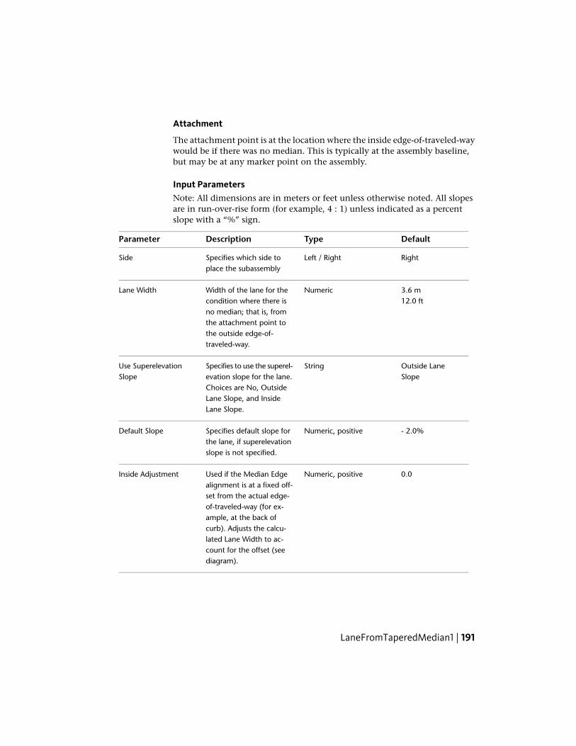
Attachment
The attachment point is at the location where the inside edge-of-traveled-waywould be if there was no median. This is typically at the assembly baseline,but may be at any marker point on the assembly.
Input ParametersNote: All dimensions are in meters or feet unless otherwise noted. All slopesare in run-over-rise form (for example, 4 : 1) unless indicated as a percentslope with a “%” sign.
DefaultTypeDescriptionParameter
RightLeft / RightSpecifies which side toplace the subassembly
Side
3.6 mNumericWidth of the lane for thecondition where there is
Lane Width12.0 ft
no median; that is, fromthe attachment point tothe outside edge-of-traveled-way.
Outside LaneSlope
StringSpecifies to use the superel-evation slope for the lane.
Use SuperelevationSlope
Choices are No, OutsideLane Slope, and InsideLane Slope.
- 2.0%Numeric, positiveSpecifies default slope forthe lane, if superelevationslope is not specified.
Default Slope
0.0Numeric, positiveUsed if the Median Edgealignment is at a fixed off-
Inside Adjustment
set from the actual edge-of-traveled-way (for ex-ample, at the back ofcurb). Adjusts the calcu-lated Lane Width to ac-count for the offset (seediagram).
LaneFromTaperedMedian1 | 191
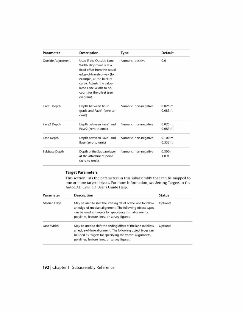
DefaultTypeDescriptionParameter
0.0Numeric, positiveUsed if the Outside LaneWidth alignment is at a
Outside Adjustment
fixed offset from the actualedge-of-traveled-way (forexample, at the back ofcurb). Adjusts the calcu-lated Lane Width to ac-count for the offset (seediagram).
0.025 mNumeric, non-negativeDepth between finishgrade and Pave1 (zero toomit)
Pave1 Depth0.083 ft
0.025 mNumeric, non-negativeDepth between Pave1 andPave2 (zero to omit)
Pave2 Depth0.083 ft
0.100 mNumeric, non-negativeDepth between Pave1 andBase (zero to omit)
Base Depth0.333 ft
0.300 mNumeric, non-negativeDepth of the Subbase layerat the attachment point
Subbase Depth1.0 ft
(zero to omit)
Target ParametersThis section lists the parameters in this subassembly that can be mapped toone or more target objects. For more information, see Setting Targets in theAutoCAD Civil 3D User’s Guide Help.
StatusDescriptionParameter
OptionalMay be used to shift the starting offset of the lane to followan edge-of-median alignment. The following object types
Median Edge
can be used as targets for specifying this: alignments,polylines, feature lines, or survey figures.
OptionalMay be used to shift the ending offset of the lane to followan edge-of-lane alignment. The following object types can
Lane Width
be used as targets for specifying the width: alignments,polylines, feature lines, or survey figures.
192 | Chapter 1 Subassembly Reference

StatusDescriptionParameter
OptionalMay be used to override the normal lane slope and tie theouter edge of the travel lane to the elevation of a profile.
Outside Elevation
The following object types can be used as targets for spe-cifying the elevation: profiles, 3D polylines, feature lines,or survey figures.
Output Parameters
TypeDescriptionParameter
NumericWidth of the laneLane Width
Numeric% slope of the laneLane %Slope
Behavior
Outside Edge-of-Traveled-Way: The width to the outside edge-of-traveled-waycan be defined by a fixed numeric width, or an alignment can be used tooverride the width. The elevation is determined by applying the specifiedslope for the width of the lane, unless an Outside Elevation profile is given.In that case, the outside edge elevation is tied to the profile, and the slope isadjusted.
The location of the inside edge-of-traveled-way is calculated based on thethree cases shown in the preceding diagram. If no Median Edge alignment isgiven, or the given one is not found at a station, the inside edge is held at theattachment point (Case 1). If a Median Edge alignment is given, and thatalignment is outside the lane’s attachment point, the inside edge is shiftedoutward from the attachment point at lane slope (Case 2). If the Median Edgealignment is inside the lane’s attachment point, the inside edge is shiftedinward from the attachment point at the lane slope (Case 3).
Inside and Outside Adjustments: The Inside Adjustment and OutsideAdjustment parameters are provided in case the alignment used for the medianedge or lane edge is at a fixed offset from the actual edge-of-traveled-way. Forexample, the alignment being used for the Median Edge may be at theback-of-curb instead of at the pavement edge. In this case the InsideAdjustment parameter should be set to the width of the curb.
LaneFromTaperedMedian1 | 193
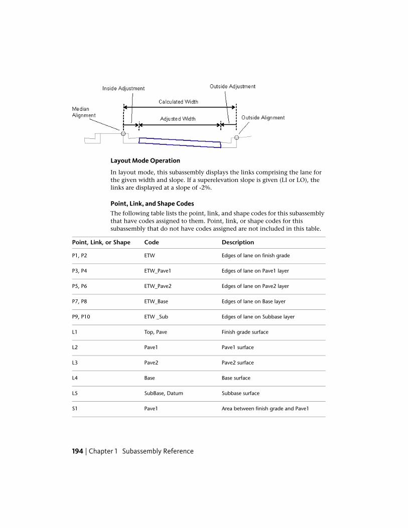
Layout Mode Operation
In layout mode, this subassembly displays the links comprising the lane forthe given width and slope. If a superelevation slope is given (LI or LO), thelinks are displayed at a slope of -2%.
Point, Link, and Shape CodesThe following table lists the point, link, and shape codes for this subassemblythat have codes assigned to them. Point, link, or shape codes for thissubassembly that do not have codes assigned are not included in this table.
DescriptionCodePoint, Link, or Shape
Edges of lane on finish gradeETWP1, P2
Edges of lane on Pave1 layerETW_Pave1P3, P4
Edges of lane on Pave2 layerETW_Pave2P5, P6
Edges of lane on Base layerETW_BaseP7, P8
Edges of lane on Subbase layerETW _SubP9, P10
Finish grade surfaceTop, PaveL1
Pave1 surfacePave1L2
Pave2 surfacePave2L3
Base surfaceBaseL4
Subbase surfaceSubBase, DatumL5
Area between finish grade and Pave1Pave1S1
194 | Chapter 1 Subassembly Reference

DescriptionCodePoint, Link, or Shape
Area between Pave1 and Pave2Pave2S2
Area between Pave2 and BaseBaseS3
Area between Base and SubbaseSubbaseS4
Coding Diagram
LaneFromTaperedMedian2This subassembly inserts one or more travel lanes outward from an alignmentthat defines the edge of a median.
The alignment defining the edge of the median may at times be either notpresent (Case 1), outside the roadway centerline (Case 2), or inside thecenterline (Case 3).
To use this subassembly, you should have separate alignments defining theleft and right edges of the median. It may be necessary to define separatecorridor model regions for each individual median. This subassembly differsfrom LaneFromTaperedMedian1 in that it provides for a grade break withdifferent slopes in the travel lanes.
LaneFromTaperedMedian2 | 195

196 | Chapter 1 Subassembly Reference

Attachment
The attachment point is at the location where the inside edge-of-traveled-waywould be if there was no median. This is typically at the assembly baseline.
LaneFromTaperedMedian2 | 197
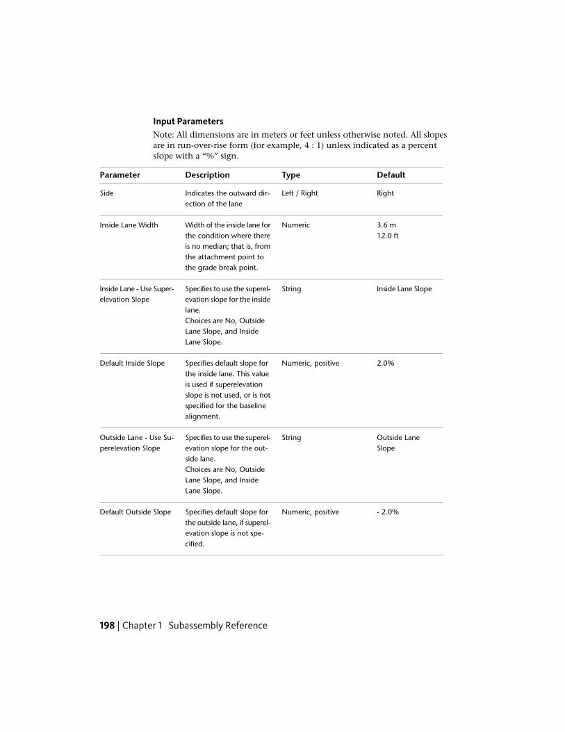
Input ParametersNote: All dimensions are in meters or feet unless otherwise noted. All slopesare in run-over-rise form (for example, 4 : 1) unless indicated as a percentslope with a “%” sign.
DefaultTypeDescriptionParameter
RightLeft / RightIndicates the outward dir-ection of the lane
Side
3.6 mNumericWidth of the inside lane forthe condition where there
Inside Lane Width12.0 ft
is no median; that is, fromthe attachment point tothe grade break point.
Inside Lane SlopeStringSpecifies to use the superel-evation slope for the insidelane.
Inside Lane - Use Super-elevation Slope
Choices are No, OutsideLane Slope, and InsideLane Slope.
2.0%Numeric, positiveSpecifies default slope forthe inside lane. This value
Default Inside Slope
is used if superelevationslope is not used, or is notspecified for the baselinealignment.
Outside LaneSlope
StringSpecifies to use the superel-evation slope for the out-side lane.
Outside Lane - Use Su-perelevation Slope
Choices are No, OutsideLane Slope, and InsideLane Slope.
- 2.0%Numeric, positiveSpecifies default slope forthe outside lane, if superel-
Default Outside Slope
evation slope is not spe-cified.
198 | Chapter 1 Subassembly Reference
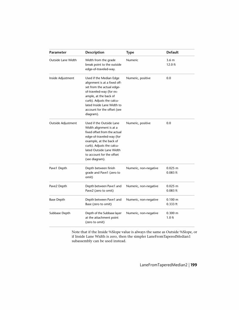
DefaultTypeDescriptionParameter
3.6 mNumericWidth from the gradebreak point to the outsideedge-of-traveled-way.
Outside Lane Width12.0 ft
0.0Numeric, positiveUsed if the Median Edgealignment is at a fixed off-
Inside Adjustment
set from the actual edge-of-traveled-way (for ex-ample, at the back ofcurb). Adjusts the calcu-lated Inside Lane Width toaccount for the offset (seediagram).
0.0Numeric, positiveUsed if the Outside LaneWidth alignment is at a
Outside Adjustment
fixed offset from the actualedge-of-traveled-way (forexample, at the back ofcurb). Adjusts the calcu-lated Outside Lane Widthto account for the offset(see diagram).
0.025 mNumeric, non-negativeDepth between finishgrade and Pave1 (zero toomit)
Pave1 Depth0.083 ft
0.025 mNumeric, non-negativeDepth between Pave1 andPave2 (zero to omit)
Pave2 Depth0.083 ft
0.100 mNumeric, non-negativeDepth between Pave1 andBase (zero to omit)
Base Depth0.333 ft
0.300 mNumeric, non-negativeDepth of the Subbase layerat the attachment point(zero to omit)
Subbase Depth1.0 ft
Note that if the Inside %Slope value is always the same as Outside %Slope, orif Inside Lane Width is zero, then the simpler LaneFromTaperedMedian1subassembly can be used instead.
LaneFromTaperedMedian2 | 199

Target ParametersThis section lists the parameters in this subassembly that can be mapped toone or more target objects. For more information, see Setting Targets in theAutoCAD Civil 3D User’s Guide Help.
StatusDescriptionParameter
OptionalMay be used to shift the starting offset of the lane tofollow an edge-of-median alignment. The following ob-
Median Edge
ject types can be used as targets for specifying this:alignments, polylines, feature lines, or survey figures.
OptionalMay be used to override the fixed Inside Lane Width andtie the grade break to an offset alignment. The following
Inside Lane Width
object types can be used as targets for specifying thewidth: alignments, polylines, feature lines, or survey fig-ures.
OptionalMay be used to override the fixed Outside Lane Widthand tie the edge-of-lane to an offset alignment. The fol-
Outside LaneWidth
lowing object types can be used as targets for specifyingthe width: alignments, polylines, feature lines, or surveyfigures.
OptionalMay be used to override the normal lane slope and tiethe outer edge of the travel lane to the elevation of a
Outside Elevation
profile. The following object types can be used as targetsfor specifying the elevation: profiles, 3D polylines, featurelines, or survey figures.
Output Parameters
TypeDescriptionParameter
NumericWidth of the inside laneInside Lane Width
Numeric% slope of the inside laneInside Lane %Slope
NumericWidth of the outside laneOutside Lane Width
Numeric% slope of the outside laneOutside Lane %Slope
200 | Chapter 1 Subassembly Reference
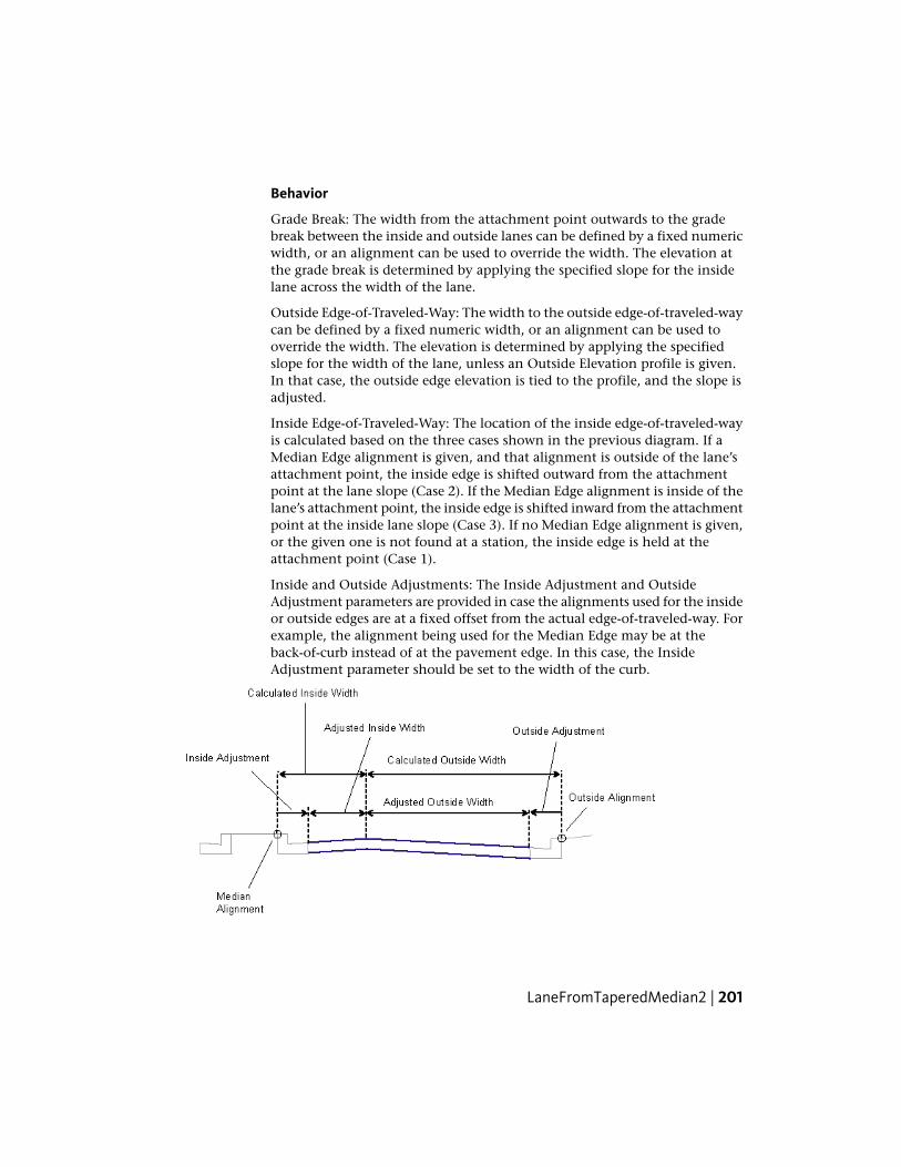
Behavior
Grade Break: The width from the attachment point outwards to the gradebreak between the inside and outside lanes can be defined by a fixed numericwidth, or an alignment can be used to override the width. The elevation atthe grade break is determined by applying the specified slope for the insidelane across the width of the lane.
Outside Edge-of-Traveled-Way: The width to the outside edge-of-traveled-waycan be defined by a fixed numeric width, or an alignment can be used tooverride the width. The elevation is determined by applying the specifiedslope for the width of the lane, unless an Outside Elevation profile is given.In that case, the outside edge elevation is tied to the profile, and the slope isadjusted.
Inside Edge-of-Traveled-Way: The location of the inside edge-of-traveled-wayis calculated based on the three cases shown in the previous diagram. If aMedian Edge alignment is given, and that alignment is outside of the lane’sattachment point, the inside edge is shifted outward from the attachmentpoint at the lane slope (Case 2). If the Median Edge alignment is inside of thelane’s attachment point, the inside edge is shifted inward from the attachmentpoint at the inside lane slope (Case 3). If no Median Edge alignment is given,or the given one is not found at a station, the inside edge is held at theattachment point (Case 1).
Inside and Outside Adjustments: The Inside Adjustment and OutsideAdjustment parameters are provided in case the alignments used for the insideor outside edges are at a fixed offset from the actual edge-of-traveled-way. Forexample, the alignment being used for the Median Edge may be at theback-of-curb instead of at the pavement edge. In this case, the InsideAdjustment parameter should be set to the width of the curb.
LaneFromTaperedMedian2 | 201
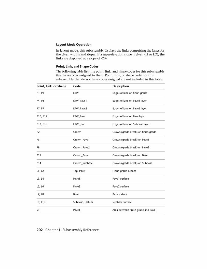
Layout Mode Operation
In layout mode, this subassembly displays the links comprising the lanes forthe given widths and slopes. If a superelevation slope is given (LI or LO), thelinks are displayed at a slope of -2%.
Point, Link, and Shape CodesThe following table lists the point, link, and shape codes for this subassemblythat have codes assigned to them. Point, link, or shape codes for thissubassembly that do not have codes assigned are not included in this table.
DescriptionCodePoint, Link, or Shape
Edges of lane on finish gradeETWP1, P3
Edges of lane on Pave1 layerETW_Pave1P4, P6
Edges of lane on Pave2 layerETW_Pave2P7, P9
Edges of lane on Base layerETW_BaseP10, P12
Edges of lane on Subbase layerETW _SubP13, P15
Crown (grade break) on finish gradeCrownP2
Crown (grade break) on Pave1Crown_Pave1P5
Crown (grade break) on Pave2Crown_Pave2P8
Crown (grade break) on BaseCrown_BaseP11
Crown (grade break) on SubbaseCrown_SubbaseP14
Finish grade surfaceTop, PaveL1, L2
Pave1 surfacePave1L3, L4
Pave2 surfacePave2L5, L6
Base surfaceBaseL7, L8
Subbase surfaceSubBase, DatumL9, L10
Area between finish grade and Pave1Pave1S1
202 | Chapter 1 Subassembly Reference

DescriptionCodePoint, Link, or Shape
Area between Pave1 and Pave2Pave2S2
Area between Pave2 and BaseBaseS3
Area between Base and SubbaseSubbaseS4
Coding Diagram
LaneInsideSuperThis subassembly creates a cross-sectional representation of finish grade, baselayer, and subbase layer for a travel lane, applying the Inside Lanesuperelevation slope value for the corridor model’s baseline alignment.
It is used for the inside lanes on divided, broken-back highways. The pavementstructure follows the standards described in “Pavement Structure on PavedSections” in the AutoCAD Civil 3D Help.
LaneInsideSuper | 203

Attachment
The attachment point is at the inside edge of lane on the finish grade surface.This component can be attached to either the left or right side.
Input ParametersNote: All dimensions are in meters or feet unless otherwise noted. All slopesare in run-over-rise form (for example, 4 : 1) unless indicated as a percentslope with a “%” sign.
DefaultTypeDescriptionParameter
RightLeft / RightSpecifies which side toplace the subassembly
Side
NoYes / NoSpecifies that inside edgeof travelway to be codedas Crown
Crown Point on Inside
3.6 mNumeric, positiveWidth of the lane from theoffset of the inside edge to
Width12.0 ft
the offset of the outsideedge
-2.0NumericDefault % Slope of thelane to be used when the
Default %Slope
superelevation slope of thealignment is not defined
0.025 mNumeric, non-negativeThickness of the Pave1 lay-er (zero to omit)
Pave1 Depth0.083 ft
204 | Chapter 1 Subassembly Reference

DefaultTypeDescriptionParameter
0.025 mNumeric, non-negativeThickness of the Pave2 lay-er (zero to omit)
Pave2 Depth0.083 ft
0.100 mNumeric, non-negativeThickness of the Base layer(zero to omit)
Base Depth0.333 ft
0.300 mNumeric, non-negativeThickness of the Subbaselayer (zero to omit)
Subbase Depth1.0 ft
Target ParametersThis section lists the parameters in this subassembly that can be mapped toone or more target objects. For more information, see Setting Targets in theAutoCAD Civil 3D User’s Guide Help.
StatusDescriptionParameter
OptionalMay be used to override the fixed lane Width and tie theedge-of-lane to an offset alignment. The following object
Width
types can be used as targets for specifying the width:alignments, polylines, feature lines, or survey figures.
OptionalMay be used to override the normal lane slope and tiethe outer edge of the travel lane to the elevation of a
Outside Elevation
profile. The following object types can be used as targetsfor specifying the elevation: profiles, 3D polylines, featurelines, or survey figures.
Output Parameters
TypeDescriptionParameter
NumericWidth of the laneLane Width
Numeric% slope of the laneLane %Slope
Behavior
The Inside Lane superelevation slope is obtained from the superelevationspecifications for the baseline alignment. Starting at the attachment point, afinish grade surface and parallel subgrade are inserted using the given width,
LaneInsideSuper | 205

depth, and the superelevation slope. Vertical links close the shape at eitherend of the lane.
If an offset horizontal alignment name is assigned to the Width during corridormodeling, the width of the lane will vary to match the offset of the alignment.
Layout Mode Operation
In layout mode, this subassembly displays the lane links using the given widthand depths at a slope of -2%.
Point, Link, and Shape CodesThe following table lists the point, link, and shape codes for this subassemblythat have codes assigned to them. Point, link, or shape codes for thissubassembly that do not have codes assigned are not included in this table.
DescriptionCodePoint, Link, or Shape
Edge-of-traveled-way on finish gradeETWP1
Crown point on finish grade (optional)CrownP1
Outside edge of lane on finish gradeLaneP2
Edge-of-traveled-way on the Pave1 layerETW_Pave1P3
Crown point on the Pave1 layer (optional)Crown_Pave1P3
Outside edge of lane on the Pave1 layerLane_Pave1P4
Edge-of-traveled-way on the Pave2 layerETW_Pave2P5
Crown point on the Pave2 layer (optional)Crown_Pave2P5
Outside edge of lane on the Pave2 layerLane_Pave2P6
206 | Chapter 1 Subassembly Reference

DescriptionCodePoint, Link, or Shape
Edge-of-traveled-way edge of lane on theBase layer
ETW_BaseP7
Crown point on base layer (optional)Crown_BaseP7
Outside edge of lane on the Base layerLane_BaseP8
Edge-of-traveled-way edge of lane on thesubbase layer
ETW _SubP9
Crown point on subbase layer (optional)Crown_SubP9
Outside edge of lane on the Subbaselayer
Lane_SubP10
Finish grade surfaceTop, PaveL1
Pave1L2
Pave2L3
Base surfaceBaseL4
Subbase surfaceSubBaseL5Datum
Pave1S1
Pave2S2
BaseS3
SubbaseS4
LaneInsideSuper | 207

Coding Diagram
LaneInsideSuperLayerVaryingWidthThis subassembly creates a cross-sectional representation of a lane comprisedof multiple layers. The layers can be of varying widths. It also applies theInside Lane superelevation slope value for the corridor model's baselinealignment.
Attachment
The attachment point is at the inside edge of lane on the finish grade surface.This component can be attached to either the left or right side.
208 | Chapter 1 Subassembly Reference
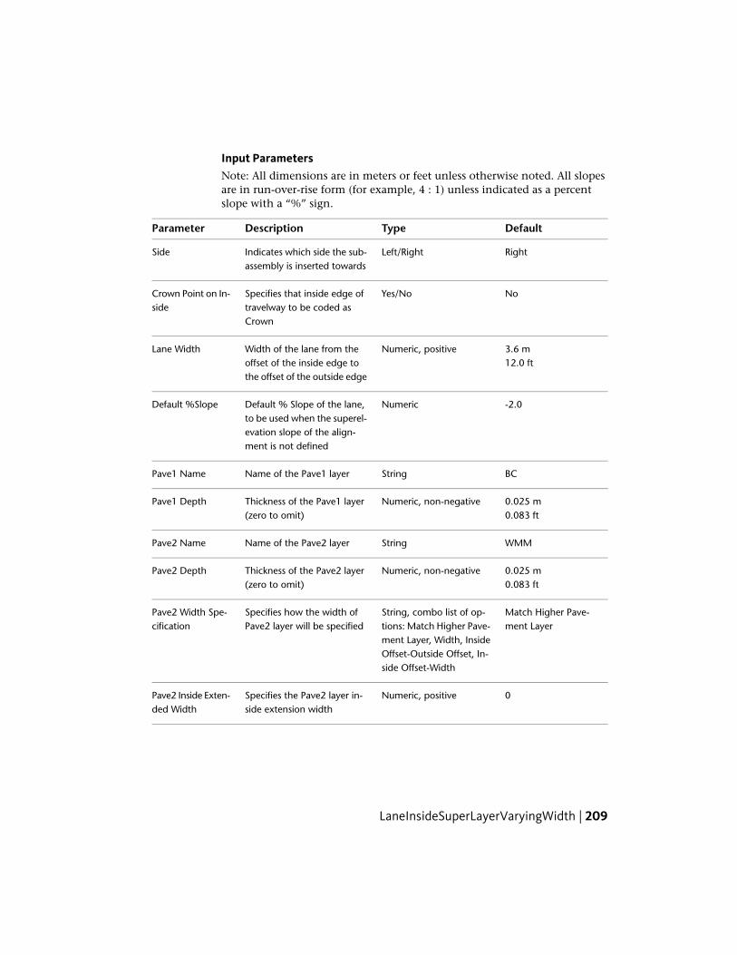
Input ParametersNote: All dimensions are in meters or feet unless otherwise noted. All slopesare in run-over-rise form (for example, 4 : 1) unless indicated as a percentslope with a “%” sign.
DefaultTypeDescriptionParameter
RightLeft/RightIndicates which side the sub-assembly is inserted towards
Side
NoYes/NoSpecifies that inside edge oftravelway to be coded asCrown
Crown Point on In-side
3.6 mNumeric, positiveWidth of the lane from theoffset of the inside edge tothe offset of the outside edge
Lane Width12.0 ft
-2.0NumericDefault % Slope of the lane,to be used when the superel-
Default %Slope
evation slope of the align-ment is not defined
BCStringName of the Pave1 layerPave1 Name
0.025 mNumeric, non-negativeThickness of the Pave1 layer(zero to omit)
Pave1 Depth0.083 ft
WMMStringName of the Pave2 layerPave2 Name
0.025 mNumeric, non-negativeThickness of the Pave2 layer(zero to omit)
Pave2 Depth0.083 ft
Match Higher Pave-ment Layer
String, combo list of op-tions: Match Higher Pave-
Specifies how the width ofPave2 layer will be specified
Pave2 Width Spe-cification
ment Layer, Width, InsideOffset-Outside Offset, In-side Offset-Width
0Numeric, positiveSpecifies the Pave2 layer in-side extension width
Pave2 Inside Exten-ded Width
LaneInsideSuperLayerVaryingWidth | 209

DefaultTypeDescriptionParameter
0Numeric, positiveSpecifies the Pave2 layer out-side extension width
Pave2 Outside Ex-tended Width
WMMStringName of the Pave3 layerPave3 Name
0.025 mNumeric, non-negativeThickness of the Pave3 layer(zero to omit)
Pave3 Depth0.083 ft
Match Higher Pave-ment Layer
String, combo list of op-tions: Match Higher Pave-
Specifies how the width ofPave3 layer will be specified
Pave3 Width Spe-cification
ment Layer, Width, InsideOffset-Outside Offset, In-side Offset-Width
0Numeric, positiveSpecifies the Pave3 layer in-side extension width
Pave3 Inside Exten-ded Width
0Numeric, positiveSpecifies the Pave3 layer out-side extension width
Pave3 Outside Ex-tended Width
WMMStringName of the Pave4 layerPave4 Name
0.025 mNumeric, non-negativeThickness of the Pave4 layer(zero to omit)
Pave4 Depth0.083 ft
Match Higher Pave-ment Layer
String, combo list of op-tions: Match Higher Pave-
Specifies how the width ofPave4 layer will be specified
Pave4 Width Spe-cification
ment Layer, Width, InsideOffset-Outside Offset, In-side Offset-Width
0Numeric, positiveSpecifies the Pave4 layer in-side extension width
Pave4 Inside Exten-ded Width
0Numeric, positiveSpecifies the Pave4 layer out-side extension width
Pave4 Outside Ex-tended Width
WMMStringName of the Pave5 layerPave5 Name
0.025 mNumeric, non-negativeThickness of the Pave5 layer(zero to omit)
Pave5 Depth0.083 ft
210 | Chapter 1 Subassembly Reference

DefaultTypeDescriptionParameter
Match Higher Pave-ment Layer
String, combo list of op-tions: Match Higher Pave-
Specifies how the width ofPave5 layer will be specified
Pave5 Width Spe-cification
ment Layer, Width, InsideOffset-Outside Offset, In-side Offset-Width
0Numeric, positiveSpecifies the Pave5 layer in-side extension width
Pave5 Inside Exten-ded Width
0Numeric, positiveSpecifies the Pave5 layer out-side extension width
Pave5 Outside Ex-tended Width
SUBBASEStringName of the Pave6 layerPave6 Name
0.025 mNumeric, non-negativeThickness of the Pave6 layer(zero to omit)
Pave6 Depth0.083 ft
Match Higher Pave-ment Layer
String, combo list of op-tions: Match Higher Pave-
Specifies how the width ofPave6 layer will be specified
Pave6 Width Spe-cification
ment Layer, Width, InsideOffset-Outside Offset, In-side Offset-Width
0Numeric, positiveSpecifies the Pave6 layer in-side extension width
Pave6 Inside Exten-ded Width
0Numeric, positiveSpecifies the Pave6 layer out-side extension width
Pave6 Outside Ex-tended Width
SUBBASEStringName of the Pave7 layerPave7 Name
0.025 mNumeric, non-negativeThickness of the Pave7 layer(zero to omit)
Pave7 Depth0.083 ft
Match Higher Pave-ment Layer
String, combo list of op-tions: Match Higher Pave-
Specifies how the width ofPave7 layer will be specified
Pave7 Width Spe-cification
ment Layer, Width, InsideOffset-Outside Offset, In-side Offset-Width
LaneInsideSuperLayerVaryingWidth | 211

DefaultTypeDescriptionParameter
0Numeric, positiveSpecifies the Pave7 layer in-side extension width
Pave7 Inside Exten-ded Width
0Numeric, positiveSpecifies the Pave7 layer out-side extension width
Pave7 Outside Ex-tended Width
StringName of the Pave8 layerPave8 Name
0.025 mNumeric, non-negativeThickness of the Pave8 layer(zero to omit)
Pave8 Depth0.083 ft
Match Higher Pave-ment Layer
String, combo list of op-tions: Match Higher Pave-
Specifies how the width ofPave8 layer will be specified
Pave8 Width Spe-cification
ment Layer, Width, InsideOffset-Outside Offset, In-side Offset-Width
0Numeric, positiveSpecifies the Pave8 layer in-side extension width
Pave8 Inside Exten-ded Width
0Numeric, positiveSpecifies the Pave8 layer out-side extension width
Pave8 Outside Ex-tended Width
StringName of the Pave9 layerPave9 Name
0.025 mNumeric, non-negativeThickness of the Pave9 layer(zero to omit)
Pave9 Depth0.083 ft
Match Higher Pave-ment Layer
String, combo list of op-tions: Match Higher Pave-
Specifies how the width ofPave9 layer will be specified
Pave9 Width Spe-cification
ment Layer, Width, InsideOffset-Outside Offset, In-side Offset-Width
0Numeric, positiveSpecifies the Pave9 layer in-side extension width
Pave9 Inside Exten-ded Width
0Numeric, positiveSpecifies the Pave9 layer out-side extension width
Pave9 Outside Ex-tended Width
StringName of the Pave10 layerPave10 Name
212 | Chapter 1 Subassembly Reference

DefaultTypeDescriptionParameter
0.025 mNumeric, non-negativeThickness of the Pave10 layer(zero to omit)
Pave10 Depth0.083 ft
Match Higher Pave-ment Layer
String, combo list of op-tions: Match Higher Pave-
Specifies how the width ofPave10 layer will be specified
Pave10 Width Spe-cification
ment Layer, Width, InsideOffset-Outside Offset, In-side Offset-Width
0Numeric, positiveSpecifies the Pave10 layer in-side extension width
Pave10 Inside Ex-tended Width
0Numeric, positiveSpecifies the Pave10 layeroutside extension width
Pave10 OutsideExtended Width
Target ParametersThis section lists the parameters in this subassembly that can be mapped toone or more target objects, such as a surface, alignment, or profile object ina drawing. For more information, see Setting Targets in the AutoCAD Civil3D User’s Guide Help.
StatusDescriptionParameter
OptionalMay be used to override the fixed lane Width and tiethe edge-of-lane to an offset alignment. The following
Lane Width
object types can be used as targets for specifying this:alignments, polylines, feature lines, or survey figures.
OptionalMay be used to override the normal lane slope and tiethe outer edge of the travel lane to the elevation of a
Outside Elevation
profile. The following object types can be used as tar-gets for specifying this elevation: profiles, 3D polylines,feature lines, or survey figures.
Output Parameters
TypeDescriptionParameter
NumericWidth of the laneLane Width
Numeric% slope of the laneLane %Slope
LaneInsideSuperLayerVaryingWidth | 213

Behavior
Each layer has its own separate extension options both on the inside andoutside. The inside and outside extensions specify the additional width onthe inside or outside relative to the pavement layer immediately above.
Example 1:
In the following example, the Pave4 Inside Extended Width is 0.5 meters. ThePave4 Outside Extended Width is zero. If this subassembly is inserted on theright side, it is drawn as shown in the following illustration.
Example 2:
In the following example, the Pave4 Inside Extended Width is 0.5 meters. ThePave4 Outside Extended Width is 0.6 meters. If this subassembly is insertedon the right side, it is drawn as shown in the following illustration.
The extension widths will always be specified as positive widths.
The pavements layer widths may be specified using the following methods:
■ by specifying that the pavement width be the same as the pavementimmediately above
■ by specifying a pavement width
■ by specifying an inside and outside pavement layer extended width so thatpavement layer width will be the distance between the inside and outsideoffsets
214 | Chapter 1 Subassembly Reference

■ by specifying an inside pavement layer extended width and pavementwidth so that the outside pavement layer is automatically calculated
Breakover removal is required if there is a change in slope of pavement whileapplying superelevation.
Layout Mode Operation
In layout mode, this subassembly displays the links defined by the inputparameters.
Point, Link, and Shape CodesThe following table lists the point, link, and shape codes for this subassemblythat have codes assigned to them. Point, link, or shape codes for thissubassembly that do not have codes assigned are not included in this table.
DescriptionCodesPoint/Link
Edge-of-traveled-way on finish gradeETWP1
Crown point on finish grade (optional)CrownP1
Outside edge of lane on finish gradeLaneP2
Edge-of-traveled-way on the Pave1 layerETW_Pave1P3
Crown point on the Pave1 layer (optional)Crown_Pave1P3
Outside edge of lane on the Pave1 layerLane_Pave1P4
Edge-of-traveled-way on the Pave2 layerETW_Pave2P5
Crown point on Pave2 layer (optional)Crown_Pave2P5
Outside edge of lane on the Pave2 layerLane_Pave2P6
Edge-of-traveled-way on the Pave3 layerETW_Pave3P7
Crown point on Pave3 layer (optional)Crown_BaseP7
Outside edge of lane on the Base layerLane_BaseP8
Edge-of-traveled-way edge of lane on the Subbase layerETW _SubP9
LaneInsideSuperLayerVaryingWidth | 215

DescriptionCodesPoint/Link
Crown point on subbase layer (optional)Crown_SubP9
Outside edge of lane on the Subbase layerLane_SubP10
Finish grade surfaceTop, PaveL1
Pave1L2
Pave2L3
Base surfaceBaseL4
Subbase surfaceSubBaseL5
Pave1S1
Pave2S2
BaseS3
SubbaseS4
Coding Diagram
LaneInsideSuperMultiLayerThis subassembly is similar to the LaneInsideSuper subassembly. However,there are additional layers within this subassembly, and the bottom layer doesnot follow the same slope as the finished grade. Instead it is controlled by aninside height and outside height.
216 | Chapter 1 Subassembly Reference

Attachment
The attachment point is at the inside edge of lane on the finish grade surface.This component can be attached to either the left or right side.
Input ParametersNote: All dimensions are in meters or feet unless otherwise noted. All slopesare in run-over-rise form (for example, 4 : 1) unless indicated as a percentslope with a “%” sign.
DefaultTypeDescriptionParameter
RightLeft / RightSpecifies which side to place thesubassembly
Side
NoYes / NoSpecifies that inside edge oftravelway to be coded as Crown
Crown Point on In-side
3.6 mNumeric, positiveWidth of the lane from the offsetof the inside edge to the offset ofthe outside edge
Width12.0 ft
-2.0NumericDefault % Slope of the lane to beused when the superelevation
Default %Slope
slope of the alignment is notdefined
0.025 mNumeric, non-neg-ative
Thickness of the Pave1 layer (zeroto omit)
Pave1 Depth0.083 ft
LaneInsideSuperMultiLayer | 217

DefaultTypeDescriptionParameter
0.025 mNumeric, non-neg-ative
Thickness of the Pave2 layer (zeroto omit)
Pave2 Depth0.083 ft
0.025 mNumeric, non-neg-ative
Thickness of the Pave3 layer (zeroto omit)
Pave 3 Depth0.083 ft
0.100 mNumeric, non-neg-ative
Thickness of the Base1 layer (zeroto omit)
Base1 Depth0.333 ft
0.100 mNumeric, non-neg-ative
Thickness of the Base2 layer (zeroto omit)
Base2 Depth0.333 ft
0.100 mNumeric, non-neg-ative
Thickness of the Base3 layer (zeroto omit)
Base3 Depth0.333 ft
0.300 mNumeric, non-neg-ative
Thickness of the Subbase1 layer(zero to omit)
Subbase1 Depth1.0 ft
0.300 mNumeric, non-neg-ative
Thickness of the Subbase2 layer(zero to omit)
Subbase2 Depth1.0 ft
0.300 mNumeric, non-neg-ative
Thickness of the Subbase3 layer atthe attachment point (zero toomit)
Subbase3 InnerDepth 1.0 ft
0.300 mNumeric, non-neg-ative
Thickness of the Subbase3 layer atthe edge of travelway (zero toomit)
Subbase3 OuterDepth 1.0 ft
Target ParametersThis section lists the parameters in this subassembly that can be mapped toone or more target objects, such as a surface, alignment, or profile object ina drawing. For more information, see Setting Targets in the AutoCAD Civil3D User’s Guide Help.
StatusTypeParameter
OptionalMay be used to override the fixed lane Width andtie the edge-of-lane to an offset alignment. The fol-
Width
lowing object types can be used as targets for spe-
218 | Chapter 1 Subassembly Reference

StatusTypeParameter
cifying this: alignments, polylines, feature lines, orsurvey figures.
OptionalMay be used to override the normal lane slope andtie the outer edge of the travel lane to the elevation
Outside Elevation
of a profile. The following object types can be usedas targets for specifying this elevation: profiles, 3Dpolylines, feature lines, or survey figures.
Output Parameters
TypeDescriptionParameter
NumericWidth of the laneLane Width
Numeric% slope of the laneLane %Slope
Behavior
This subassembly is inserted on the side of the attachment point specified.All links follow the slope specified for the top link L1, with the exception ofL10. Link L10 is determined by the Subbase3 Inner Depth and Subbase3 OuterDepth. The Pave1 and Pave2 layers in this subassembly support optionalextension of the layer widths. All other behavior of this subassembly is thesame as that of the existing LaneInsideSuper subassembly.
Layout Mode Operation
In layout mode, this subassembly displays the links defined by the inputparameters.
Point, Link, and Shape CodesThe following table lists the point, link, and shape codes for this subassemblythat have codes assigned to them. Point, link, or shape codes for thissubassembly that do not have codes assigned are not included in this table.
DescriptionCodesPoint, Link, orShape
Edge-of-traveled-way on finish gradeETWP1
Crown point on finish grade (optional)CrownP1
LaneInsideSuperMultiLayer | 219
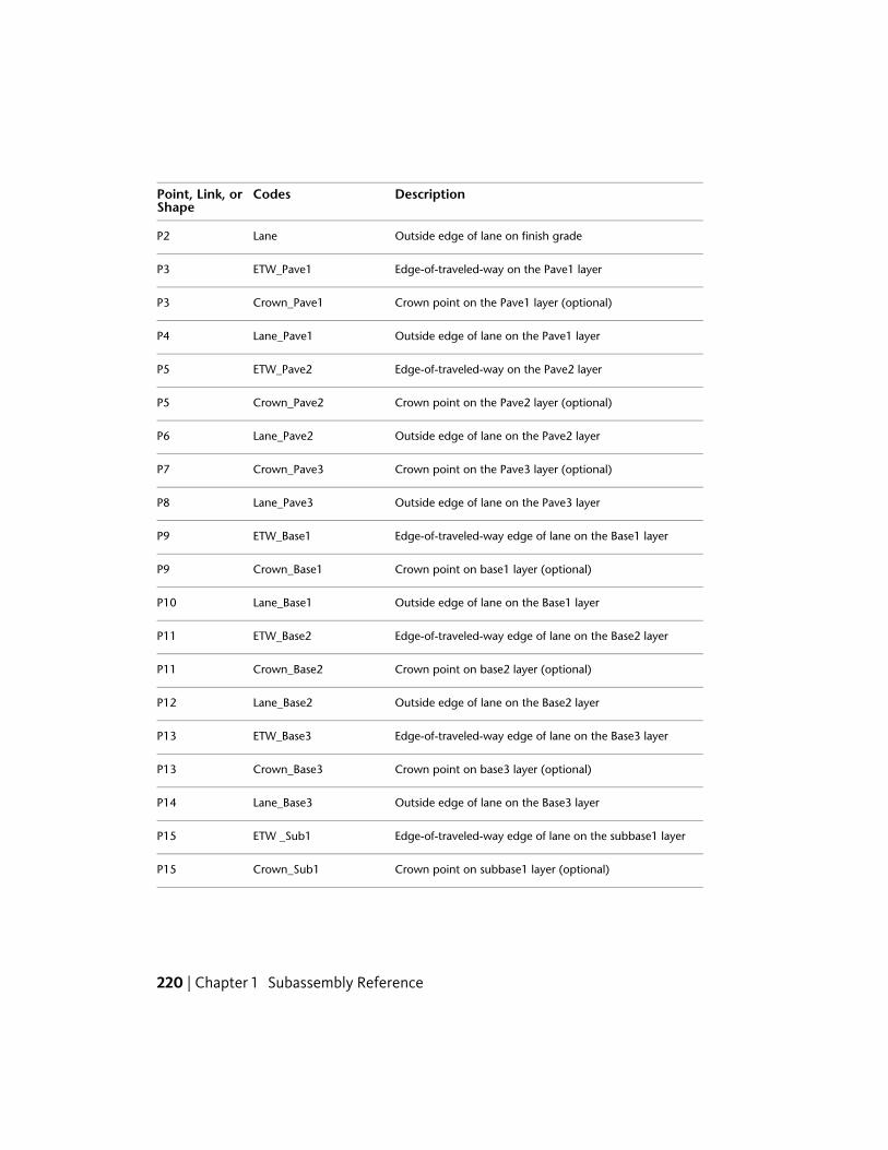
DescriptionCodesPoint, Link, orShape
Outside edge of lane on finish gradeLaneP2
Edge-of-traveled-way on the Pave1 layerETW_Pave1P3
Crown point on the Pave1 layer (optional)Crown_Pave1P3
Outside edge of lane on the Pave1 layerLane_Pave1P4
Edge-of-traveled-way on the Pave2 layerETW_Pave2P5
Crown point on the Pave2 layer (optional)Crown_Pave2P5
Outside edge of lane on the Pave2 layerLane_Pave2P6
Crown point on the Pave3 layer (optional)Crown_Pave3P7
Outside edge of lane on the Pave3 layerLane_Pave3P8
Edge-of-traveled-way edge of lane on the Base1 layerETW_Base1P9
Crown point on base1 layer (optional)Crown_Base1P9
Outside edge of lane on the Base1 layerLane_Base1P10
Edge-of-traveled-way edge of lane on the Base2 layerETW_Base2P11
Crown point on base2 layer (optional)Crown_Base2P11
Outside edge of lane on the Base2 layerLane_Base2P12
Edge-of-traveled-way edge of lane on the Base3 layerETW_Base3P13
Crown point on base3 layer (optional)Crown_Base3P13
Outside edge of lane on the Base3 layerLane_Base3P14
Edge-of-traveled-way edge of lane on the subbase1 layerETW _Sub1P15
Crown point on subbase1 layer (optional)Crown_Sub1P15
220 | Chapter 1 Subassembly Reference
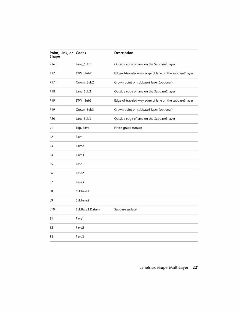
DescriptionCodesPoint, Link, orShape
Outside edge of lane on the Subbase1 layerLane_Sub1P16
Edge-of-traveled-way edge of lane on the subbase2 layerETW _Sub2P17
Crown point on subbase2 layer (optional)Crown_Sub2P17
Outside edge of lane on the Subbase2 layerLane_Sub2P18
Edge-of-traveled-way edge of lane on the subbase3 layerETW _Sub3P19
Crown point on subbase3 layer (optional)Crown_Sub3P19
Outside edge of lane on the Subbase3 layerLane_Sub3P20
Finish grade surfaceTop, PaveL1
Pave1L2
Pave2L3
Pave3L4
Base1L5
Base2L6
Base3L7
Subbase1L8
Subbase2L9
Subbase surfaceSubBase3 DatumL10
Pave1S1
Pave2S2
Pave3S3
LaneInsideSuperMultiLayer | 221
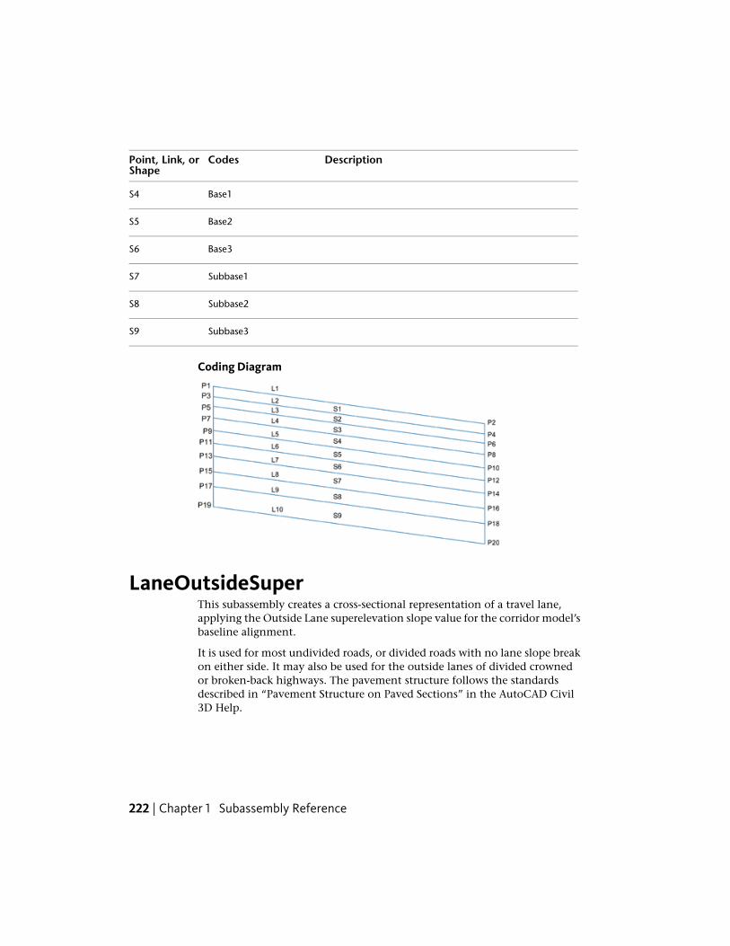
DescriptionCodesPoint, Link, orShape
Base1S4
Base2S5
Base3S6
Subbase1S7
Subbase2S8
Subbase3S9
Coding Diagram
LaneOutsideSuperThis subassembly creates a cross-sectional representation of a travel lane,applying the Outside Lane superelevation slope value for the corridor model’sbaseline alignment.
It is used for most undivided roads, or divided roads with no lane slope breakon either side. It may also be used for the outside lanes of divided crownedor broken-back highways. The pavement structure follows the standardsdescribed in “Pavement Structure on Paved Sections” in the AutoCAD Civil3D Help.
222 | Chapter 1 Subassembly Reference
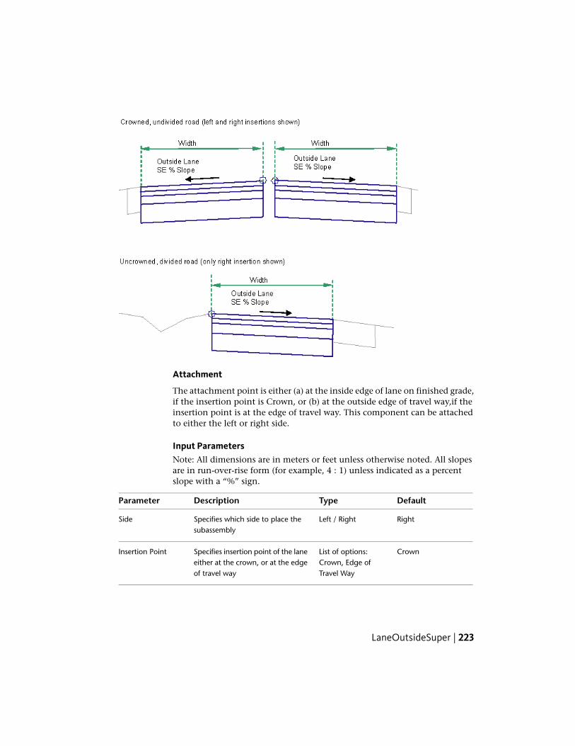
Attachment
The attachment point is either (a) at the inside edge of lane on finished grade,if the insertion point is Crown, or (b) at the outside edge of travel way,if theinsertion point is at the edge of travel way. This component can be attachedto either the left or right side.
Input ParametersNote: All dimensions are in meters or feet unless otherwise noted. All slopesare in run-over-rise form (for example, 4 : 1) unless indicated as a percentslope with a “%” sign.
DefaultTypeDescriptionParameter
RightLeft / RightSpecifies which side to place thesubassembly
Side
CrownList of options:Crown, Edge ofTravel Way
Specifies insertion point of the laneeither at the crown, or at the edgeof travel way
Insertion Point
LaneOutsideSuper | 223
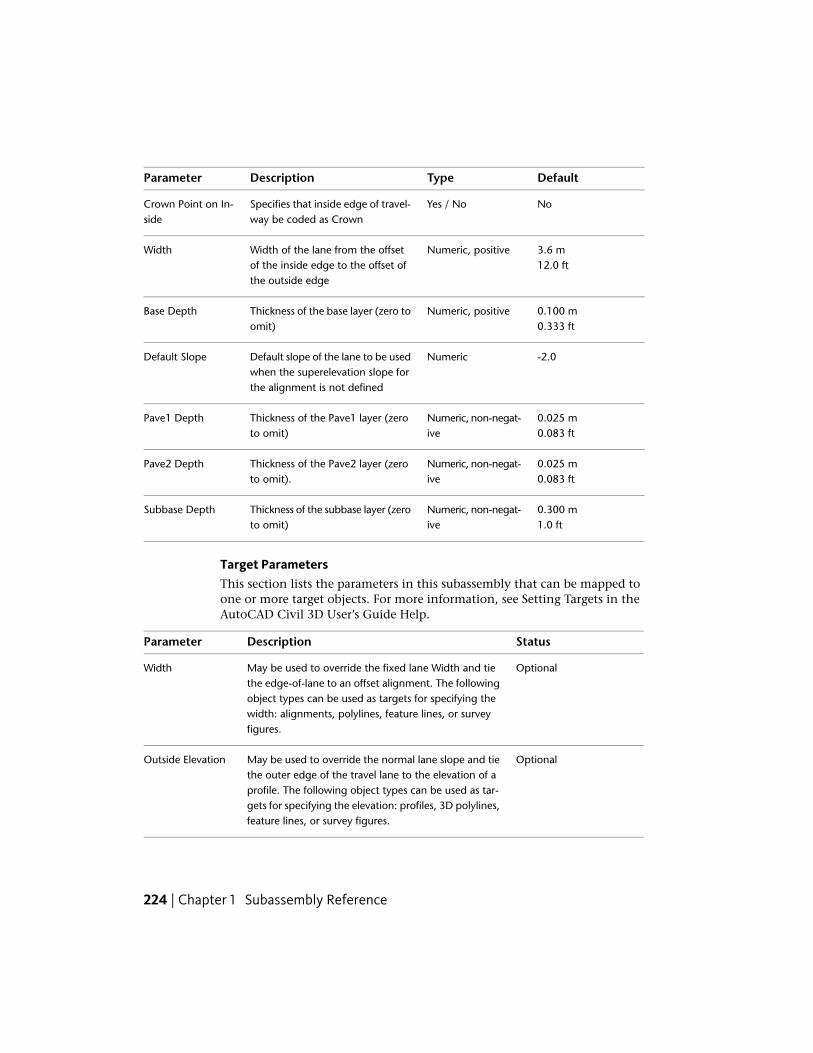
DefaultTypeDescriptionParameter
NoYes / NoSpecifies that inside edge of travel-way be coded as Crown
Crown Point on In-side
3.6 mNumeric, positiveWidth of the lane from the offsetof the inside edge to the offset ofthe outside edge
Width12.0 ft
0.100 mNumeric, positiveThickness of the base layer (zero toomit)
Base Depth0.333 ft
-2.0NumericDefault slope of the lane to be usedwhen the superelevation slope forthe alignment is not defined
Default Slope
0.025 mNumeric, non-negat-ive
Thickness of the Pave1 layer (zeroto omit)
Pave1 Depth0.083 ft
0.025 mNumeric, non-negat-ive
Thickness of the Pave2 layer (zeroto omit).
Pave2 Depth0.083 ft
0.300 mNumeric, non-negat-ive
Thickness of the subbase layer (zeroto omit)
Subbase Depth1.0 ft
Target ParametersThis section lists the parameters in this subassembly that can be mapped toone or more target objects. For more information, see Setting Targets in theAutoCAD Civil 3D User’s Guide Help.
StatusDescriptionParameter
OptionalMay be used to override the fixed lane Width and tiethe edge-of-lane to an offset alignment. The following
Width
object types can be used as targets for specifying thewidth: alignments, polylines, feature lines, or surveyfigures.
OptionalMay be used to override the normal lane slope and tiethe outer edge of the travel lane to the elevation of a
Outside Elevation
profile. The following object types can be used as tar-gets for specifying the elevation: profiles, 3D polylines,feature lines, or survey figures.
224 | Chapter 1 Subassembly Reference

Output Parameters
TypeDescriptionParameter
NumericWidth of the laneLane Width
Numeric% slope of the laneLane %Slope
Behavior
The Outside Lane superelevation slope is obtained from the superelevationspecifications for the baseline alignment. Starting at the attachment point, afinish grade surface and parallel subgrade are inserted using the given width,depth, and the superelevation slope. Vertical links close the shape at eitherend of the lane.
If an offset horizontal alignment name is assigned to the Width during corridormodeling, the width of the lane will vary to match the offset of the alignment.
Layout Mode Operation
In layout mode, this subassembly displays all lane links using the width anddepth input parameters at a -2% slope.
Point, Link, and Shape CodesThe following table lists the point, link, and shape codes for this subassemblythat have codes assigned to them. Point, link, or shape codes for thissubassembly that do not have codes assigned are not included in this table.
DescriptionCodePoint, Link, or Shape
Crown point on finish grade (optional)CrownP1
Inside edge of lane on finish gradeETWP2
Crown point on the Pave1 layer (optional)Crown_Pave1P3
Inside edge of lane on Pave.ETW_Pave1P4
Crown point on the Pave2 layer (optional)Crown_Pave2P5
Inside edge of lane on Pave2ETW_Pave2P6
Crown point on base grade (optional)Crown_BaseP7
LaneOutsideSuper | 225

DescriptionCodePoint, Link, or Shape
Inside edge of lane on BaseETW_BaseP8
Crown point on subbase grade (optional)Crown_SubP9
Inside edge of lane on SubbaseETW_SubP10
Finish grade surfaceTop, PaveL1
Pave1 surfacePave1L2
Pave2 surfacePave2L3
Base surfaceBaseL4
Subbase surfaceSubbaseL5Datum
Area between finish grade and Pave1Pave1S1
Area between Pave1 and Pave2Pave2S2
Area between Pave2 and BaseBaseS3
Area between Base and SubbaseSubbaseS4
Coding Diagram
LaneOutsideSuperLayerVaryingWidthThis subassembly creates a cross-sectional representation of a lane comprisedof multiple layers. The layers can be of varying widths. It also applies the
226 | Chapter 1 Subassembly Reference

Inside Lane superelevation slope value for the corridor model's baselinealignment.
Attachment
The attachment point is at the inside edge of lane on the finish grade surface.This component can be attached to either the left or right side.
Input ParametersNote: All dimensions are in meters or feet unless otherwise noted. All slopesare in run-over-rise form (for example, 4 : 1) unless indicated as a percentslope with a “%” sign.
DefaultTypeDescriptionParameter
RightLeft/RightIndicates which side thesubassembly is inserted to-wards
Side
NoYes/NoSpecifies that inside edgeof travelway to be codedas Crown
Crown Point on Inside
3.6 mNumeric, positiveWidth of the lane from theoffset of the inside edge to
Lane Width12.0 ft
the offset of the outsideedge
-2.0NumericDefault % Slope of thelane, to be used when the
Default %Slope
LaneOutsideSuperLayerVaryingWidth | 227
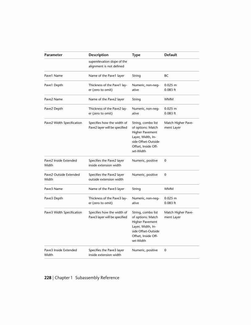
DefaultTypeDescriptionParameter
superelevation slope of thealignment is not defined
BCStringName of the Pave1 layerPave1 Name
0.025 mNumeric, non-neg-ative
Thickness of the Pave1 lay-er (zero to omit)
Pave1 Depth0.083 ft
WMMStringName of the Pave2 layerPave2 Name
0.025 mNumeric, non-neg-ative
Thickness of the Pave2 lay-er (zero to omit)
Pave2 Depth0.083 ft
Match Higher Pave-ment Layer
String, combo listof options: Match
Specifies how the width ofPave2 layer will be specified
Pave2 Width Specification
Higher PavementLayer, Width, In-side Offset-OutsideOffset, Inside Off-set-Width
0Numeric, positiveSpecifies the Pave2 layerinside extension width
Pave2 Inside ExtendedWidth
0Numeric, positiveSpecifies the Pave2 layeroutside extension width
Pave2 Outside ExtendedWidth
WMMStringName of the Pave3 layerPave3 Name
0.025 mNumeric, non-neg-ative
Thickness of the Pave3 lay-er (zero to omit)
Pave3 Depth0.083 ft
Match Higher Pave-ment Layer
String, combo listof options: Match
Specifies how the width ofPave3 layer will be specified
Pave3 Width Specification
Higher PavementLayer, Width, In-side Offset-OutsideOffset, Inside Off-set-Width
0Numeric, positiveSpecifies the Pave3 layerinside extension width
Pave3 Inside ExtendedWidth
228 | Chapter 1 Subassembly Reference

DefaultTypeDescriptionParameter
0Numeric, positiveSpecifies the Pave3 layeroutside extension width
Pave3 Outside ExtendedWidth
WMMStringName of the Pave4 layerPave4 Name
0.025 mNumeric, non-neg-ative
Thickness of the Pave4 lay-er (zero to omit)
Pave4 Depth0.083 ft
Match Higher Pave-ment Layer
String, combo listof options: Match
Specifies how the width ofPave4 layer will be specified
Pave4 Width Specification
Higher PavementLayer, Width, In-side Offset-OutsideOffset, Inside Off-set-Width
0Numeric, positiveSpecifies the Pave4 layerinside extension width
Pave4 Inside ExtendedWidth
0Numeric, positiveSpecifies the Pave4 layeroutside extension width
Pave4 Outside ExtendedWidth
WMMStringName of the Pave5 layerPave5 Name
0.025 mNumeric, non-neg-ative
Thickness of the Pave5 lay-er (zero to omit)
Pave5 Depth0.083 ft
Match Higher Pave-ment Layer
String, combo listof options: Match
Specifies how the width ofPave5 layer will be specified
Pave5 Width Specification
Higher PavementLayer, Width, In-side Offset-OutsideOffset, Inside Off-set-Width
0Numeric, positiveSpecifies the Pave5 layerinside extension width
Pave5 Inside ExtendedWidth
0Numeric, positiveSpecifies the Pave5 layeroutside extension width
Pave5 Outside ExtendedWidth
LaneOutsideSuperLayerVaryingWidth | 229

DefaultTypeDescriptionParameter
SUBBASEStringName of the Pave6 layerPave6 Name
0.025 mNumeric, non-neg-ative
Thickness of the Pave6 lay-er (zero to omit)
Pave6 Depth0.083 ft
Match Higher Pave-ment Layer
String, combo listof options: Match
Specifies how the width ofPave6 layer will be specified
Pave6 Width Specification
Higher PavementLayer, Width, In-side Offset-OutsideOffset, Inside Off-set-Width
0Numeric, positiveSpecifies the Pave6 layerinside extension width
Pave6 Inside ExtendedWidth
0Numeric, positiveSpecifies the Pave6 layeroutside extension width
Pave6 Outside ExtendedWidth
SubbaseStringName of the Pave7 layerPave7 Name
0.025 mNumeric, non-neg-ative
Thickness of the Pave7 lay-er (zero to omit)
Pave7 Depth0.083 ft
Match Higher Pave-ment Layer
String, combo listof options: Match
Specifies how the width ofPave7 layer will be specified
Pave7 Width Specification
Higher PavementLayer, Width, In-side Offset-OutsideOffset, Inside Off-set-Width
0Numeric, positiveSpecifies the Pave7 layerinside extension width
Pave7 Inside ExtendedWidth
0Numeric, positiveSpecifies the Pave7 layeroutside extension width
Pave7 Outside ExtendedWidth
StringName of the Pave8 layerPave8 Name
230 | Chapter 1 Subassembly Reference

DefaultTypeDescriptionParameter
0.025 mNumeric, non-neg-ative
Thickness of the Pave8 lay-er (zero to omit)
Pave8 Depth0.083 ft
Match Higher Pave-ment Layer
String, combo listof options: Match
Specifies how the width ofPave8 layer will be specified
Pave8 Width Specification
Higher PavementLayer, Width, In-side Offset-OutsideOffset, Inside Off-set-Width
0Numeric, positiveSpecifies the Pave8 layerinside extension width
Pave8 Inside ExtendedWidth
0Numeric, positiveSpecifies the Pave8 layeroutside extension width
Pave8 Outside ExtendedWidth
StringName of the Pave9 layerPave9 Name
0.025 mNumeric, non-neg-ative
Thickness of the Pave9 lay-er (zero to omit)
Pave9 Depth0.083 ft
Match Higher Pave-ment Layer
String, combo listof options: Match
Specifies how the width ofPave9 layer will be specified
Pave9 Width Specification
Higher PavementLayer, Width, In-side Offset-OutsideOffset, Inside Off-set-Width
0Numeric, positiveSpecifies the Pave9 layerinside extension width
Pave9 Inside ExtendedWidth
0Numeric, positiveSpecifies the Pave9 layeroutside extension width
Pave9 Outside ExtendedWidth
StringName of the Pave10 layerPave10 Name
0.025 mNumeric, non-neg-ative
Thickness of the Pave10layer (zero to omit)
Pave10 Depth0.083 ft
LaneOutsideSuperLayerVaryingWidth | 231

DefaultTypeDescriptionParameter
Match Higher Pave-ment Layer
String, combo listof options: Match
Specifies how the width ofPave10 layer will be spe-cified
Pave10 Width Specification
Higher PavementLayer, Width, In-side Offset-OutsideOffset, Inside Off-set-Width
0Numeric, positiveSpecifies the Pave10 layerinside extension width
Pave10 Inside ExtendedWidth
0Numeric, positiveSpecifies the Pave10 layeroutside extension width
Pave10 Outside ExtendedWidth
Target ParametersThis section lists the parameters in this subassembly that can be mapped toone or more target objects, such as a surface, alignment, or profile object ina drawing. For more information, see Setting Targets in the AutoCAD Civil3D User’s Guide Help.
StatusDescriptionParameter
OptionalMay be used to override the fixed lane Width and tiethe edge-of-lane to an offset alignment. The following
Lane Width
object types can be used as targets for specifying this:alignments, polylines, feature lines, or survey figures.
OptionalMay be used to override the normal lane slope and tiethe outer edge of the travel lane to the elevation of a
Outside Elevation
profile. The following object types can be used as tar-gets for specifying this elevation: profiles, 3D polylines,feature lines, or survey figures.
Output Parameters
TypeDescriptionParameter
NumericWidth of the laneLane Width
Numeric% slope of the laneLane %Slope
232 | Chapter 1 Subassembly Reference

Behavior
Each layer has its own separate extension options both on the inside andoutside. The inside and outside extensions specify the additional width onthe inside or outside relative to the pavement layer immediately above.
Example 1:
Pave4 Inside Extended Width = 0.5m
Pave4 Outside Extended Width = 0m
If inserted on the right side,
Example 2:
Pave4 Inside Extended Width = 0.5m
Pave4 Outside Extended Width = 0.6m
If inserted on the right side,
The extension widths will always be specified as positive widths.
The pavements layer widths may be specified using the following methods:
■ By specifying that the pavement width will be the same as the pavementimmediately above.
■ By specifying a pavement width.
LaneOutsideSuperLayerVaryingWidth | 233

By specifying an inside and outside pavement layer extended width so thatpavement layer width will be the distance between the inside and outsideoffsets.
By specifying an inside pavement layer extended width and pavement widthso that the outside pavement layer is automatically calculated.
Breakover removal is required if there is a change in slope of pavement whileapplying superelevation.
Layout Mode Operation
In layout mode, this subassembly displays the links defined by the inputparameters.
Point, Link, and Shape CodesThe following table lists the point, link, and shape codes for this subassemblythat have codes assigned to them. Point, link, or shape codes for thissubassembly that do not have codes assigned are not included in this table.
DescriptionCodesPoint/Link
Edge-of-traveled-way on finish gradeETWP1
Crown point on finish grade (optional)CrownP1
Outside edge of lane on finish gradeLaneP2
Edge-of-traveled-way on the Pave1 layerETW_Pave1P3
Crown point on the Pave1 layer (optional)Crown_Pave1P3
Outside edge of lane on the Pave1 layerLane_Pave1P4
Edge-of-traveled-way on the Pave2 layerETW_Pave2P5
Crown point on Pave2 layer (optional)Crown_Pave2P5
Outside edge of lane on the Pave2 layerLane_Pave2P6
Edge-of-traveled-way on the Pave3 layerETW_Pave3P7
Crown point on Pave3 layer (optional)Crown_BaseP7
Outside edge of lane on the Base layerLane_BaseP8
234 | Chapter 1 Subassembly Reference

DescriptionCodesPoint/Link
Edge-of-traveled-way edge of lane on the Subbase layerETW _SubP9
Crown point on subbase layer (optional)Crown_SubP9
Outside edge of lane on the Subbase layerLane_SubP10
Finish grade surfaceTop, PaveL1
Pave1L2
Pave2L3
Base surfaceBaseL4
Subbase surfaceSubBaseL5
Pave1S1
Pave2S2
BaseS3
SubbaseS4
Coding Diagram
LaneOutsideSuperMultiLayerThis subassembly is similar to the LaneOutsideSuper subassembly. However,there are additional layers within this subassembly, and the bottom layer does
LaneOutsideSuperMultiLayer | 235

not follow the same slope as the finished grade. Instead it is controlled by aninside height and outside height.
Attachment
The attachment point is either (a) at the inside edge of lane on finished grade,if the insertion point is Crown, or (b) at the outside edge of travel way,if theinsertion point is at the edge of travel way. This component can be attachedto either the left or right side.
Input ParametersNote: All dimensions are in meters or feet unless otherwise noted. All slopesare in run-over-rise form (for example, 4 : 1) unless indicated as a percentslope with a “%” sign.
DefaultTypeDescriptionParameter
RightLeft / RightSpecifies which side to place thesubassembly
Side
CrownList of options:Crown, Edge ofTravel Way
Specifies insertion point of thelane either at the crown, or at theedge of travel way
Insertion Point
NoYes / NoSpecifies that inside edge oftravelway be coded as Crown
Crown Point onInside
3.6 mNumeric, positiveWidth of the lane from the offsetof the inside edge to the offset ofthe outside edge
Width12.0 ft
236 | Chapter 1 Subassembly Reference

DefaultTypeDescriptionParameter
-2.0NumericDefault % Slope of the lane to beused when the superelevation
Default %Slope
slope of the alignment is notdefined
0.025 mNumeric, non-negative
Thickness of the Pave1 layer (zeroto omit)
Pave1 Depth0.083 ft
0.025 mNumeric, non-negative
Thickness of the Pave2 layer (zeroto omit)
Pave2 Depth0.083 ft
0.025 mNumeric, non-negative
Thickness of the Pave3 layer (zeroto omit)
Pave 3 Depth0.083 ft
0.100 mNumeric, non-negative
Thickness of the Base1 layer (zeroto omit)
Base1 Depth0.333 ft
0.100 mNumeric, non-negative
Thickness of the Base2 layer (zeroto omit)
Base2 Depth0.333 ft
0.100 mNumeric, non-negative
Thickness of the Base3 layer (zeroto omit)
Base3 Depth0.333 ft
0.300 mNumeric, non-negative
Thickness of the Subbase1 layer(zero to omit)
Subbase1Depth 1.0 ft
0.300 mNumeric, non-negative
Thickness of the Subbase2 layer(zero to omit)
Subbase2Depth 1.0 ft
0.300 mNumeric, non-negative
Thickness of the Subbase3 layerat the attachment point (zero toomit)
Subbase3 InnerDepth 1.0 ft
0.300 mNumeric, non-negative
Thickness of the Subbase3 layerat the edge of travelway (zero toomit)
Subbase3 OuterDepth 1.0 ft
Target ParametersThis section lists the parameters in this subassembly that can be mapped toone or more target objects, such as a surface, alignment, or profile object in
LaneOutsideSuperMultiLayer | 237
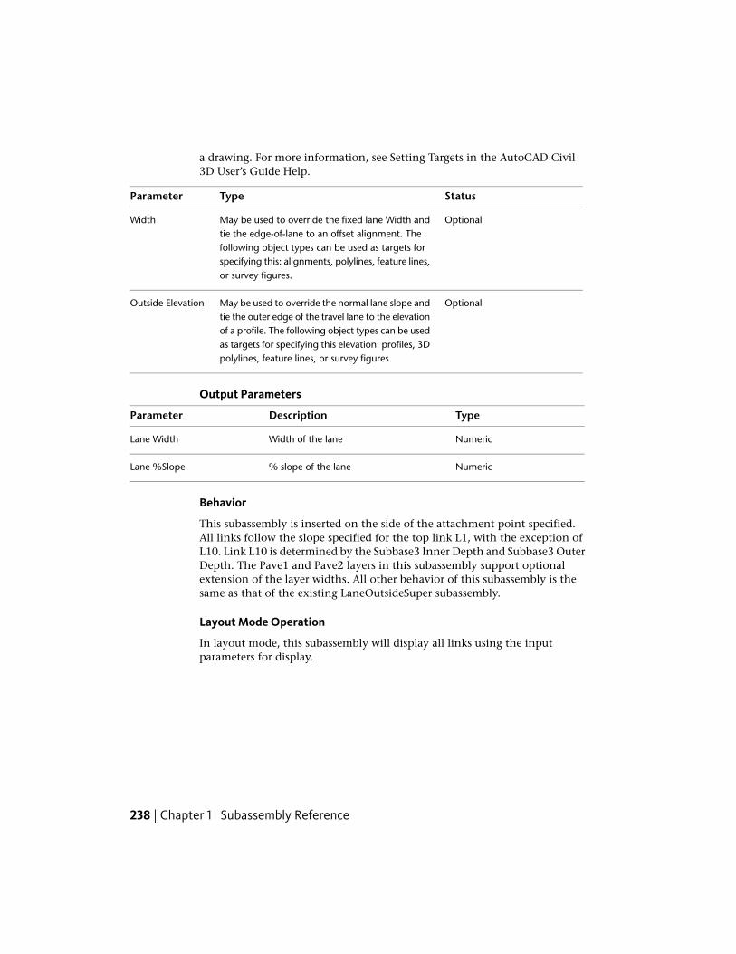
a drawing. For more information, see Setting Targets in the AutoCAD Civil3D User’s Guide Help.
StatusTypeParameter
OptionalMay be used to override the fixed lane Width andtie the edge-of-lane to an offset alignment. The
Width
following object types can be used as targets forspecifying this: alignments, polylines, feature lines,or survey figures.
OptionalMay be used to override the normal lane slope andtie the outer edge of the travel lane to the elevation
Outside Elevation
of a profile. The following object types can be usedas targets for specifying this elevation: profiles, 3Dpolylines, feature lines, or survey figures.
Output Parameters
TypeDescriptionParameter
NumericWidth of the laneLane Width
Numeric% slope of the laneLane %Slope
Behavior
This subassembly is inserted on the side of the attachment point specified.All links follow the slope specified for the top link L1, with the exception ofL10. Link L10 is determined by the Subbase3 Inner Depth and Subbase3 OuterDepth. The Pave1 and Pave2 layers in this subassembly support optionalextension of the layer widths. All other behavior of this subassembly is thesame as that of the existing LaneOutsideSuper subassembly.
Layout Mode Operation
In layout mode, this subassembly will display all links using the inputparameters for display.
238 | Chapter 1 Subassembly Reference

Point, Link, and Shape CodesThe following table lists the point, link, and shape codes for this subassemblythat have codes assigned to them. Point, link, or shape codes for thissubassembly that do not have codes assigned are not included in this table.
DescriptionCodesPoint, Link, orShape
Edge-of-traveled-way on finish gradeETWP1
Crown point on finish grade (optional)CrownP1
Outside edge of lane on finish gradeLaneP2
Edge-of-traveled-way on the Pave1 layerETW_Pave1P3
Crown point on the Pave1 layer (optional)Crown_Pave1P3
Outside edge of lane on the Pave1 layerLane_Pave1P4
Edge-of-traveled-way on the Pave2 layerETW_Pave2P5
Crown point on the Pave2 layer (optional)Crown_Pave2P5
Outside edge of lane on the Pave2 layerLane_Pave2P6
Crown point on the Pave3 layer (optional)Crown_Pave3P7
Outside edge of lane on the Pave3 layerLane_Pave3P8
Edge-of-traveled-way edge of lane on the Base1 layerETW_Base1P9
Crown point on base1 layer (optional)Crown_Base1P9
Outside edge of lane on the Base1 layerLane_Base1P10
Edge-of-traveled-way edge of lane on the Base2 layerETW_Base2P11
Crown point on base2 layer (optional)Crown_Base2P11
Outside edge of lane on the Base2 layerLane_Base2P12
Edge-of-traveled-way edge of lane on the Base3 layerETW_Base3P13
LaneOutsideSuperMultiLayer | 239

DescriptionCodesPoint, Link, orShape
Crown point on base3 layer (optional)Crown_Base3P13
Outside edge of lane on the Base3 layerLane_Base3P14
Edge-of-traveled-way edge of lane on the subbase1 layerETW _Sub1P15
Crown point on subbase1 layer (optional)Crown_Sub1P15
Outside edge of lane on the Subbase1 layerLane_Sub1P16
Edge-of-traveled-way edge of lane on the subbase2 layerETW _Sub2P17
Crown point on subbase2 layer (optional)Crown_Sub2P17
Outside edge of lane on the Subbase2 layerLane_Sub2P18
Edge-of-traveled-way edge of lane on the subbase3 layerETW _Sub3P19
Crown point on subbase3 layer (optional)Crown_Sub3P19
Outside edge of lane on the Subbase3 layerLane_Sub3P20
Finish grade surfaceTop, PaveL1
Pave1L2
Pave2L3
Pave3L4
Base1L5
Base2L6
Base3L7
Subbase1L8
Subbase2L9
240 | Chapter 1 Subassembly Reference

DescriptionCodesPoint, Link, orShape
Subbase surfaceSubBase3 DatumL10
Pave1S1
Pave2S2
Pave3S3
Base1S4
Base2S5
Base3S6
Subbase1S7
Subbase2S8
Subbase3S9
Coding Diagram
LaneOutsideSuperWithWideningThis subassembly inserts a travel lane, applying the Outside Lane superelevationslope value, and widens the pavement at superelevated regions.
LaneOutsideSuperWithWidening | 241

It can be used for most undivided roads, or divided roads with no lane slopebreak on either side. It may also be used for the outside lanes of dividedcrowned or broken-back highways. The pavement structure follows thestandards described in “Pavement Structure on Paved Sections” in the AutoCADCivil 3D Help. The only difference between this subassembly and theLaneOutsideSuper subassembly is that this subassembly also widens thepavement width in superelevated regions of the corridor.
Attachment
The attachment point is (a) at the inside edge of lane on finished grade, if theinsertion point is Crown, or (b) at the outside edge of travel way,if the insertionpoint is at the edge of travel way. This component can be attached to eitherthe left or right side.
242 | Chapter 1 Subassembly Reference

Input ParametersNote: All dimensions are in meters or feet unless otherwise noted. All slopesare in run-over-rise form (for example, 4 : 1) unless indicated as a percentslope with a “%” sign.
DefaultTypeDescriptionParameter
RightLeft / RightSpecifies which side to place thesubassembly
Side
CrownList of options: (a)Crown, (b) Edge ofTravel Way
Specifies insertion point of the laneeither at the crown, or at the edgeof travel way
Insertion Point
NoYes / NoSpecifies that the inside edge oftravelway be coded as Crown
Crown Point on In-side
3.6 mNumeric, positiveWidth of the lane from the offsetof the inside edge to the offset ofthe outside edge
Width12.0 ft
-2.0NumericDefault % slope of the lane to beused when the superelevation slopefor the alignment is not defined
Default %Slope
0.025 mNumeric, non-negat-ive
Thickness of the Pave1 layer (zeroto omit)
Pave1 Depth0.083 ft
0.025 mNumeric, non-negat-ive
Thickness of the Pave2 layer (zeroto omit)
Pave2 Depth0.083 ft
0.100 mNumeric, non-negat-ive
Thickness of the base layer(zero to omit)
Base Depth0.333 ft
0.300 mNumeric, non-negat-ive
Thickness of the subbase layer(zero to omit)
Subbase Depth1.0 ft
10 mNumeric, positiveLength of the vehicle wheelbase,including front overhang
Wheelbase Length33 ft
1Integer, positiveNumber of planned travel lanes inthis subassembly
Number of TravelLanes
LaneOutsideSuperWithWidening | 243

Target ParametersThis section lists the parameters in this subassembly that can be mapped toone or more target objects. For more information, see Setting Targets in theAutoCAD Civil 3D User’s Guide.
StatusDescriptionParameter
OptionalMay be used to override the fixed lane Width and tiethe edge-of-lane to an offset alignment. The following
Width
object types can be used as targets for specifying thewidth: alignments, polylines, feature lines, or surveyfigures.
OptionalMay be used to override the normal lane slope and tiethe outer edge of the travel lane to the elevation of a
Outside Elevation
profile. The following object types can be used as targetsfor specifying the elevation: profiles, 3D polylines, featurelines, or survey figures.
Output Parameters
TypeDescriptionParameter
NumericWidth of the laneLane Width
Numeric% slope of the laneLane %Slope
Behavior
The Outside Lane superelevation slope is obtained from the superelevationspecifications for the baseline alignment. Starting at the attachment point, afinish grade surface and parallel subgrade are inserted using the given width,depth, and the superelevation slope. Vertical links close the shape at eitherend of the lane.
Lane Widening
If the current station is within a superelevated region, then the lane widthvalue is calculated as follows:
Width = Default Width + Pavement Widening
where Pavement Widening =
244 | Chapter 1 Subassembly Reference
n = Number of lanes
R = Radius of the alignment at full superelevation
L = Length of wheelbase including the front overhang
The lane should be widened starting from the "End Normal Crown" and bythe time "full super" station lane should be "default width + pavementwidening". If spirals are used, typically this widening transition length is equalto the length of the spiral.
The key steps in completing this conditional subassembly are:
1 Set pavement widening to zero.
2 Get the default width from parameters.
3 Verify whether a station is in Superelevation zone or not.
4 If Yes, then find the radius of curvature at full super station (not currentstation).
5 Compute the pavement widening value from the equation mentionedin the spec (ExtraW).
6 Find out the station value of “End Normal Crown” in this region; andsimilarly find station value of “Full Super”; find the difference as lengthalong alignment to distribute (L).
7 Divide ExtraW by L and get that factor RateW.
8 For the current station, find the difference between “end normal crown”station and current station (DeltaL).
9 Multiply RateW by DeltaL to get DeltaW for the current station.
10 Add the DeltaW to the default Width provided in the subassemblyproperties.
11 Hence, the new width at the current station is = Width+DeltaW.
The DeltaW is the only parameter (note that it is not an input parameter) thatis shown in the following diagram.
LaneOutsideSuperWithWidening | 245

The preceding diagram is not accurate, but indicative. The black line representscenterline and the blue lines on left and right denotes edges of different laneson right and left sides (after design). The light (gray) colored lines in thediagram indicate original right and left edges. The deviation of the designededges is due to the provision of extra widening.
If an offset horizontal alignment name is assigned to the Width during corridormodeling, the width of the lane will vary to match the offset of the alignment.
Layout Mode Operation
In layout mode, this subassembly displays all lane links using the width anddepth input parameters at a -2% slope.
Point, Link, and Shape CodesThe following table lists the point, link, and shape codes for this subassemblythat have codes assigned to them. Point, link, or shape codes for thissubassembly that do not have codes assigned are not included in this table.
DescriptionCodePoint, Link, or Shape
Inside edge of lane on finish gradeETWP2
Inside edge of lane on Pave1.ETW_Pave1P4
Inside edge of lane on Pave2ETW_Pave2P6
Inside edge of lane on BaseETW_BaseP8
246 | Chapter 1 Subassembly Reference

DescriptionCodePoint, Link, or Shape
Inside edge of lane on SubbaseETW_SubP10
Finish grade surfaceTop, PaveL1
Pave1 surfacePave1L2
Pave2 surfacePave2L3
Base surfaceBaseL4
Subbase surfaceSubbaseL5
Area between finish grade and Pave1Pave1S1
Area between Pave1 and Pave2Pave2S2
Area between Pave2 and BaseBaseS3
Area between Base and SubbaseSubbaseS4
Coding Diagram
LaneParabolicThis subassembly creates a cross-sectional representation of finish grade,pavement, and subbase for urban, parabolic lanes between the left and rightedges of traveled way.
The parabolic shape is simulated by a series of short, straight-line links. Nosuperelevation is applied to the travel lanes. The pavement structure followsthe standards described in “Pavement Structure on Paved Sections” in theAutoCAD Civil 3D Help.
LaneParabolic | 247

Attachment
The attachment point is at the crown of road on the finish grade surface. Thiscomponent is symmetrical about the attachment point.
Input ParametersNote: All dimensions are in meters or feet unless otherwise noted. All slopesare in run-over-rise form (for example, 4 : 1) unless indicated as a percentslope with a “%” sign.
DefaultTypeDescriptionParameter
0.10 mNumeric, positiveHeight from the center point of thestring line to the crown of road
Crown Height0.3333 ft.
7.2 mNumeric, positiveWidth of the roadway from the leftedge-of-traveled-way to the rightedge-of-traveled-way
Width24.0 ft
0.025 mNumeric, non-negat-ive
Depth between the finish grade andthe Pave1 surface (zero to omit)
Pave1 Depth0.083 ft
0.025 mNumeric, non-negat-ive
Depth between the Pave1 and Pave2surfaces (zero to omit)
Pave2 Depth0.083 ft
0.100 mNumeric, non-negat-ive
Depth between the Pave2 and Basesurfaces (zero to omit)
Base Depth0.333 ft
0.300 mNumeric, non-negat-ive
Depth between the Base and Subbasesurfaces (zero to omit)
Subbase Depth1.0 ft
248 | Chapter 1 Subassembly Reference

DefaultTypeDescriptionParameter
0 (%)Numeric% slope of the string line from the leftETW to the right ETW
%Slope
8Numeric, positive,even
Number of straight line incrementssimulating the parabolic shape
No. Increments
Target Parameters
This section lists the parameters in this subassembly that can be mapped toone or more target objects. For more information, see Setting Targets in theAutoCAD Civil 3D User’s Guide Help.
Target Parameters: None.
Output Parameters
None.
Behavior
The center of the string line is calculated by subtracting the Crown Heightfrom the attachment point, and the left and right edges-of-traveled-way arecalculated by applying the Width and Slope symmetrically about theattachment point. The ordinates of the parabolic curve are calculated at evenintervals along the string line, and straight line links are added to connect theordinate points. Parallel surfaces are inserted for the Pave1, Pave2, Base, andSubbase surfaces from the given depths.
Layout Mode Operation
In layout mode, this subassembly displays the lane links calculated from thegiven input parameters.
Point, Link, and Shape CodesThe following table lists the point, link, and shape codes for this subassemblythat have codes assigned to them. Point, link, or shape codes for thissubassembly that do not have codes assigned are not included in this table.
DescriptionCodePoint, Link, or Shape
Outside edges of lane on finish gradeETW
LaneParabolic | 249
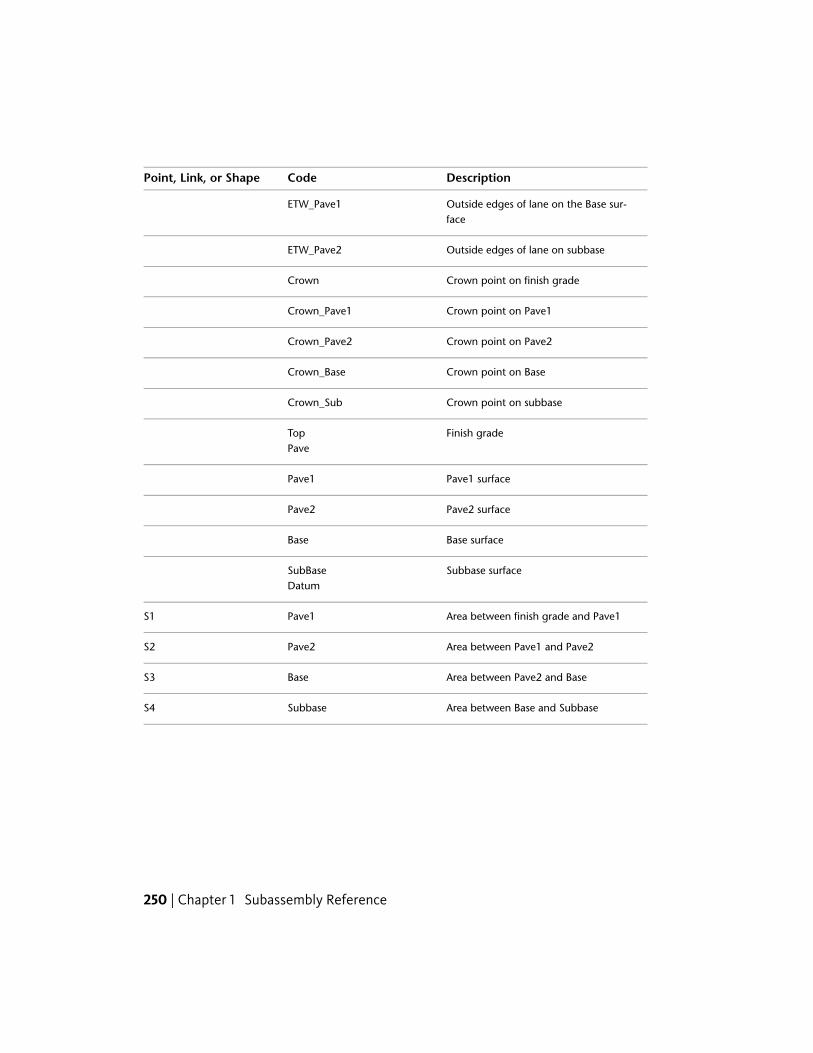
DescriptionCodePoint, Link, or Shape
Outside edges of lane on the Base sur-face
ETW_Pave1
Outside edges of lane on subbaseETW_Pave2
Crown point on finish gradeCrown
Crown point on Pave1Crown_Pave1
Crown point on Pave2Crown_Pave2
Crown point on BaseCrown_Base
Crown point on subbaseCrown_Sub
Finish gradeTopPave
Pave1 surfacePave1
Pave2 surfacePave2
Base surfaceBase
Subbase surfaceSubBaseDatum
Area between finish grade and Pave1Pave1S1
Area between Pave1 and Pave2Pave2S2
Area between Pave2 and BaseBaseS3
Area between Base and SubbaseSubbaseS4
250 | Chapter 1 Subassembly Reference

Coding Diagram
LaneTowardCrownThis subassembly creates a cross-sectional representation of a travel lane thatis being inserted from the inside edge of pavement towards the crown point.
It uses the Outside Lane superelevation slope value for the corridor model’sbaseline alignment. The pavement structure follows the standards describedin “Pavement Structure on Paved Sections” in the AutoCAD Civil 3D Help.
Attachment
The attachment point is at the inside edge of lane on the finish grade surface.This component can be attached to either the left or right side.
LaneTowardCrown | 251

Input ParametersNote: All dimensions are in meters or feet unless otherwise noted. All slopesare in run-over-rise form (for example, 4 : 1) unless indicated as a percentslope with a “%” sign.
DefaultTypeDescriptionParameter
RightLeft / RightSpecifies which side to place the sub-assembly
Side
YesYes / NoSpecifies that the inside edge oftravelway be coded as Crown
Crown Point on In-side
3.6 mNumeric, positiveWidth of the lane from the offset ofthe inside edge to the offset of theoutside edge
Width12.0 ft
0.025 mNumeric, non-negat-ive
Thickness of the Pave1 layer (zero toomit)
Pave1 Depth0.083 ft
0.025 mNumeric, non-negat-ive
Thickness of the Pave2 layer (zero toomit)
Pave2 Depth0.083 ft
0.100 mNumeric, non-negat-ive
Thickness of the Base layer (zero toomit)
Base Depth0.333 ft
0.300 mNumeric, non-negat-ive
Thickness of the Subbase layer (zeroto omit)
Subbase Depth1.0 ft
Target ParametersThis section lists the parameters in this subassembly that can be mapped toone or more target objects. For more information, see Setting Targets in theAutoCAD Civil 3D User’s Guide Help.
StatusDescriptionParameter
OptionalMay be used to override the fixed lane Width valueand tie the edge-of-lane to an offset alignment.
Width
The following object types can be used as targetsfor specifying the width: alignments, polylines,feature lines, or survey figures.
252 | Chapter 1 Subassembly Reference

StatusDescriptionParameter
OptionalMay be used to override the normal lane slope andtie the outer edge of the travel lane to the elevation
Crown Elevation
of a profile. The following object types can be usedas targets for specifying the elevation: profiles, 3Dpolylines, feature lines, or survey figures.
Output Parameters
TypeDescriptionParameter
NumericWidth slope of the laneLane Width
Numeric% slope of the laneLane %Slope
Behavior
The Inside Lane superelevation slope is obtained from the superelevationspecifications for the baseline alignment, and the algebraic sign of this valueis reversed. If inserting to the left, the Right Outside Lane Slope is obtainedand reversed; if inserting to the right, the Left Outside Lane Slope is obtainedand reversed. Starting at the attachment point, a finish grade surface andparallel subgrade are inserted using the given width, depth, and the reversesuperelevation slope. Vertical links close the shape at either end of the lane.
If an offset horizontal alignment name is assigned to the Width during corridormodeling, the width of the lane will vary to match the offset of the alignment.
Layout Mode Operation
In layout mode, this subassembly displays the finish, base, and subbase linksfor the given width and depths at a -2% slope.
LaneTowardCrown | 253
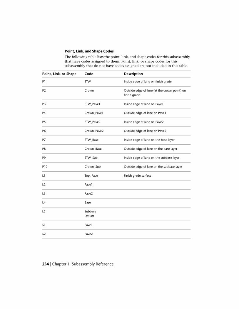
Point, Link, and Shape CodesThe following table lists the point, link, and shape codes for this subassemblythat have codes assigned to them. Point, link, or shape codes for thissubassembly that do not have codes assigned are not included in this table.
DescriptionCodePoint, Link, or Shape
Inside edge of lane on finish gradeETWP1
Outside edge of lane (at the crown point) onfinish grade
CrownP2
Inside edge of lane on Pave1ETW_Pave1P3
Outside edge of lane on Pave1Crown_Pave1P4
Inside edge of lane on Pave2ETW_Pave2P5
Outside edge of lane on Pave2Crown_Pave2P6
Inside edge of lane on the base layerETW_BaseP7
Outside edge of lane on the base layerCrown_BaseP8
Inside edge of lane on the subbase layerETW_SubP9
Outside edge of lane on the subbase layerCrown_SubP10
Finish grade surfaceTop, PaveL1
Pave1L2
Pave2L3
BaseL4
SubbaseL5Datum
Pave1S1
Pave2S2
254 | Chapter 1 Subassembly Reference
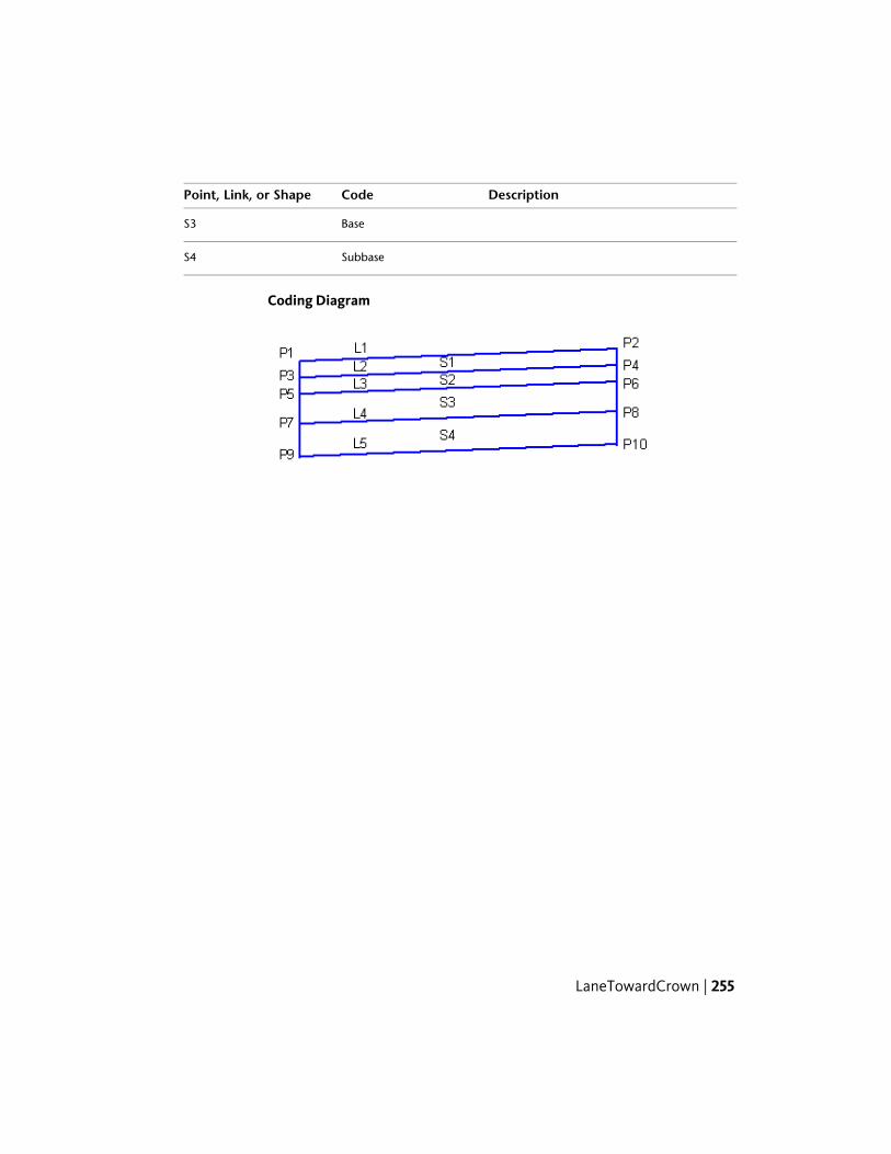
DescriptionCodePoint, Link, or Shape
BaseS3
SubbaseS4
Coding Diagram
LaneTowardCrown | 255

256

Subassembly Reference(continued)
The subassemblies in this subassembly reference are organized alphabetically into the followingsections:
■ Subassembly Reference - Introduction through LaneTowardCrown (page 1)
■ Subassembly Reference (continued)- LinkMulti through OverlayWidenWithSuper1 (thissection)
■ Subassembly Reference (continued) - RailSingle through UrbanSidewalk (page 407)
LinkMultiThis subassembly is a general purpose subassembly to add a series of connectedlinks.
This is typically used to add structural shapes that are not pre-defined assubassemblies. Up to 12 links may be specified. If a shape requires more than12 links, the LinkMulti subassembly can be used multiple times.
2
257

Attachment
The attachment point is at the beginning of the first link. The subassemblyis sensitive to the direction being inserted. Positive widths increase the offsetfrom the attachment point in the direction inserted.
Input ParametersNote: All dimensions are in meters or feet unless otherwise noted. All slopesare in run-over-rise form (for example, 4 : 1) unless indicated as a percentslope with a “%” sign.
DefaultTypeDescriptionParameter
RightLeft / RightSpecifies which side to placethe subassembly
Side
0Numeric, positive in-teger
The number of links used todraw the shape
No. of Links
Top, DatumComma-separatedstring
A list of codes to be assignedto the link
Link Codes
MultiLink_PointComma-separatedstring
A list of point codes to be as-signed for each vertex in thissubassembly
Point Codes
MultiLinkComma-separatedstring
A list of point codes to be as-signed for the shapes formed,if any, by this subassembly
Shape Codes
0Numeric+/- width of the first link. Pos-itive widths are in the direc-tion of insertion.
dW1
0Numeric+/- vertical deflection of thefirst link
dZ1
0Numeric+/- width of the 2nd linkdW2
0Numeric+/- vertical deflection of the2nd link
dZ2
0Numeric. . .. . .(links 3 – 11)
258 | Chapter 2 Subassembly Reference (continued)
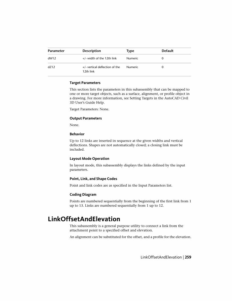
DefaultTypeDescriptionParameter
0Numeric+/- width of the 12th linkdW12
0Numeric+/- vertical deflection of the12th link
dZ12
Target Parameters
This section lists the parameters in this subassembly that can be mapped toone or more target objects, such as a surface, alignment, or profile object ina drawing. For more information, see Setting Targets in the AutoCAD Civil3D User’s Guide Help.
Target Parameters: None.
Output Parameters
None.
Behavior
Up to 12 links are inserted in sequence at the given widths and verticaldeflections. Shapes are not automatically closed; a closing link must beincluded.
Layout Mode Operation
In layout mode, this subassembly displays the links defined by the inputparameters.
Point, Link, and Shape Codes
Point and link codes are as specified in the Input Parameters list.
Coding Diagram
Points are numbered sequentially from the beginning of the first link from 1up to 13. Links are numbered sequentially from 1 up to 12.
LinkOffsetAndElevationThis subassembly is a general purpose utility to connect a link from theattachment point to a specified offset and elevation.
An alignment can be substituted for the offset, and a profile for the elevation.
LinkOffsetAndElevation | 259

Attachment
The attachment point is at the beginning of the link. The direction of the linkis determined by the location of the given offset and elevation relative to theattachment point.
Input ParametersNote: All dimensions are in meters or feet unless otherwise noted. All slopesare in run-over-rise form (for example, 4 : 1) unless indicated as a percentslope with a “%” sign.
DefaultTypeDescriptionParameter
3.0 mNumeric+/- offset of the end of the link. Spe-cifying a positive value for the this
Offsetfrom Baseline10.0 ft
parameter inserts this subassembly onthe right side of a corridor, or con-trolling baseline. A negative value in-serts it on the left side. For more in-formation, see "Inserting Subassem-blies on Right and Left Sides of a Cor-ridor" in the Corridors chapter of theAutoCAD Civil 3D User's Guide Help.
0.0NumericElevation at the end of the linkElevation
P2Comma-separatedstring
A list of surface codes to be assignedto the outside edge of the link
Point Codes
Top, DatumComma-separatedstring
A list of codes to be assigned to thelink
Link Codes
NoYes\NoThis parameter adds or removes thesurface link
Omit Link
260 | Chapter 2 Subassembly Reference (continued)
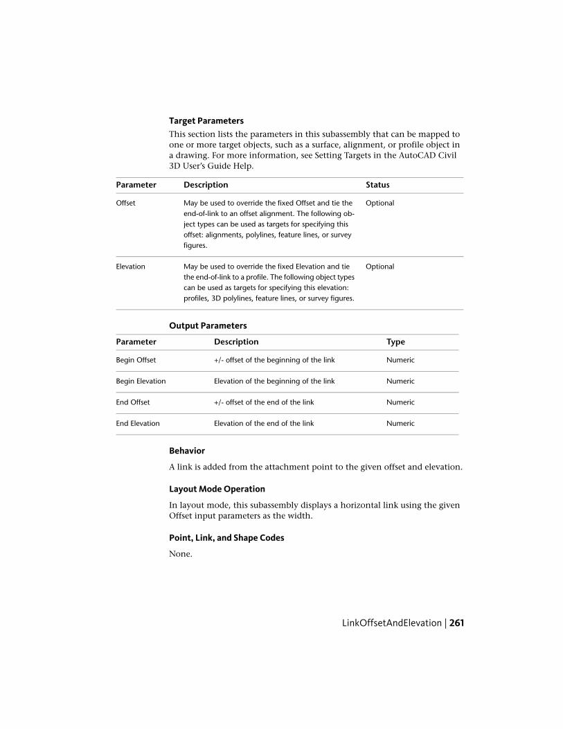
Target ParametersThis section lists the parameters in this subassembly that can be mapped toone or more target objects, such as a surface, alignment, or profile object ina drawing. For more information, see Setting Targets in the AutoCAD Civil3D User’s Guide Help.
StatusDescriptionParameter
OptionalMay be used to override the fixed Offset and tie theend-of-link to an offset alignment. The following ob-
Offset
ject types can be used as targets for specifying thisoffset: alignments, polylines, feature lines, or surveyfigures.
OptionalMay be used to override the fixed Elevation and tiethe end-of-link to a profile. The following object types
Elevation
can be used as targets for specifying this elevation:profiles, 3D polylines, feature lines, or survey figures.
Output Parameters
TypeDescriptionParameter
Numeric+/- offset of the beginning of the linkBegin Offset
NumericElevation of the beginning of the linkBegin Elevation
Numeric+/- offset of the end of the linkEnd Offset
NumericElevation of the end of the linkEnd Elevation
Behavior
A link is added from the attachment point to the given offset and elevation.
Layout Mode Operation
In layout mode, this subassembly displays a horizontal link using the givenOffset input parameters as the width.
Point, Link, and Shape Codes
None.
LinkOffsetAndElevation | 261

Coding Diagram
LinkOffsetAndSlopeThis subassembly is a general purpose utility to connect a link from theattachment point to a specified offset at a given slope.
An alignment can be substituted for the offset, and a profile for the slope.
Attachment
The attachment point is at the beginning of the link. The direction of the linkis determined by the location of the given offset and slope.
Input ParametersNote: All dimensions are in meters or feet unless otherwise noted. All slopesare in run-over-rise form (for example, 4 : 1) unless indicated as a percentslope with a “%” sign.
DefaultTypeDescriptionParameter
10.0 mNumeric+/- offset of the end of the link. Specify-ing a positive value for the this paramet-
Offset from Baseline33.0 ft
er inserts this subassembly on the rightside of a corridor, or controllingbaseline. A negative value inserts it onthe left side. For more information, see
262 | Chapter 2 Subassembly Reference (continued)

DefaultTypeDescriptionParameter
"Inserting Subassemblies on Right andLeft Sides of a Corridor" in the Cor-ridors chapter of the AutoCAD Civil 3DUser's Guide Help.
2 (%), (or2:1)
Numeric,Grade\Slope
% slope of the link. Negative slopes godownward in the direction inserted.
Slope
P2Comma-separ-ated string
A list of surface codes to be assignedto the outside edge of the link
Point Codes
Top, DatumComma-separ-ated string
A list of codes to be assigned to thelink
Link Codes
NoYes\NoThis parameter adds or removes thesurface link.
Omit Link
NoneSelection List:Specifies to use superelevation slopefor the shoulder
Use Superelevationa) OutsideShoulder Slope,b) InsideShoulder Slope,c)Outside Lane,d)Inside Lane, e)None
Target ParametersThis section lists the parameters in this subassembly that can be mapped toone or more target objects, such as a surface, alignment, or profile object ina drawing. For more information, see Setting Targets in the AutoCAD Civil3D User’s Guide Help.
StatusDescriptionParameter
OptionalMay be used to override the fixed Offset and tie theend-of-link to an offset alignment. The following object
Offset
types can be used as targets for specifying this offset:alignments, polylines, feature lines, or survey figures.
OptionalMay be used to override the fixed Slope and tie theend-of-link to a profile. The following object types can
Slope
LinkOffsetAndSlope | 263

StatusDescriptionParameter
be used as targets for specifying this elevation: profiles,3D polylines, feature lines, or survey figures.
Output Parameters
TypeDescriptionParameter
Numeric+/- offset of the beginning of the linkBegin Offset
NumericElevation of the beginning of the linkBegin Elevation
Numeric+/- offset of the end of the linkEnd Offset
NumericElevation of the end of the linkEnd Elevation
Behavior
A link is added from the attachment point to the given offset at the givenslope.
This subassembly includes an optional input parameter named UseSuperelevation Slope that lets you specify to use the superelevation slope forthe shoulder. This parameter can be set to a) Outside shoulder slope, b) Insideshoulder slope, c)Outside Lane, d)Inside Lane, or e) None. None is the defaultsetting.
If the input offset value is a negative number and superelevation slope isspecified (Use Superelevation Slope parameter not set to None), the valuesfrom the left side lane or shoulder will be used. If a positive offset is specified,the values from the right side superelevation will be used.
Layout Mode Operation
In layout mode, this subassembly displays the link calculated from the givenoffset and slope parameters.
Point, Link, and Shape Codes
None.
264 | Chapter 2 Subassembly Reference (continued)

Coding Diagram
LinkOffsetOnSurfaceThis subassembly is a general purpose utility to extend a link from theattachment point to a given offset on a target surface.
An alignment can be used when building a corridor model to calculate theoffset.
Attachment
The attachment point is at the beginning of the link.
Input ParametersNote: All dimensions are in meters or feet unless otherwise noted. All slopesare in run-over-rise form (for example, 4 : 1) unless indicated as a percentslope with a “%” sign.
DefaultTypeDescriptionParameter
0.0Numeric+/- offset to tie the link into the targetsurface. Specifying a positive value for
Offset fromBaseline
the this parameter inserts this sub-assembly on the right side of a corridor,or controlling baseline. A negative valueinserts it on the left side. For more in-formation, see "Inserting Subassemblies
LinkOffsetOnSurface | 265

DefaultTypeDescriptionParameter
on Right and Left Sides of a Corridor"in the Corridors chapter of the AutoCADCivil 3D User's Guide Help.
P2Comma-separatedstring
A list of surface codes to be assigned tothe outside edge of the link
Point Codes
Top, DatumComma-separatedstring
A list of codes to be assigned to the linkLink Codes
NoYes\NoThis parameter adds or removes thesurface link.
Omit Link
Target ParametersThis section lists the parameters in this subassembly that can be mapped toone or more target objects, such as a surface, alignment, or profile object ina drawing. For more information, see Setting Targets in the AutoCAD Civil3D User’s Guide Help.
StatusDescriptionParameter
OptionalMay be used to override the fixed Offset and tiethe end-of-link to an offset alignment. The follow-
Offset
ing object types can be used as targets for specify-ing this offset: alignments, polylines, feature lines,or survey figures.
RequiredName of the surface the link is tying to. The follow-ing object types can be used as targets for specify-ing this surface: surfaces.
Target Surface
Output Parameters
TypeDescriptionParameter
Numeric+/- offset of the beginning of the linkBegin Offset
NumericElevation of the beginning of the linkBegin Elevation
Numeric+/- offset of the end of the linkEnd Offset
266 | Chapter 2 Subassembly Reference (continued)

TypeDescriptionParameter
NumericElevation of the end of the linkEnd Elevation
Behavior
A link is extended to the point on the target surface at the given offset.
Layout Mode Operation
In layout mode, this subassembly displays the link drawn to the given offsetat a -4 : 1 slope. The link terminates with an arrowhead pointing outwards.
Point, Link, and Shape Codes
None.
Coding Diagram
LinkSlopeAndVerticalDeflectionThis subassembly is a general purpose utility to extend a link at a slope for avertical deflection distance.
A profile can be given for the vertical deflection when building a corridormodel.
LinkSlopeAndVerticalDeflection | 267

Attachment
The attachment point is at the inside edge of the link. This subassembly canbe inserted in the left or right direction from the attachment point.
Input ParametersNote: All dimensions are in meters or feet unless otherwise noted. All slopesare in run-over-rise form (for example, 4 : 1) unless indicated as a percentslope with a “%” sign.
DefaultTypeDescriptionParameter
RightLeft/RightSpecifies which side to place the subassemblySide
2 (%), (or2:1)
Numeric, positive,nonzero
% or ratio slope of the link.Slope
3.0 mNumeric.non-zero
+/- Vertical deflection between the beginning andend of the link
Vertical Deflec-tion 10.0 ft
P2Comma-sep-arated string
A list of surface codes to be assigned to the outsideedge of the link
Point Codes
Top,Datum
Comma-sep-arated string
A list of codes to be assigned to the linkLink Codes
NoYes\NoThis parameter adds or removes the surface link.Omit Link
NoneSelection List:Specifies to use superelevation slope for the shoulderUse Supereleva-tion a) Outside
ShoulderSlope, b) In-side ShoulderSlope, c)Out-side Lane,d)Inside Lane,e) None
268 | Chapter 2 Subassembly Reference (continued)

Target ParametersThis section lists the parameters in this subassembly that can be mapped toone or more target objects, such as a surface, alignment, or profile object ina drawing. For more information, see Setting Targets in the AutoCAD Civil3D User’s Guide Help.
DescriptionParameter
OptionalMay be used to override the fixed Vertical Deflectionand tie the end-of-link to a profile. The following
Vertical Deflection
object types can be used as targets for specifyingthis: profiles, 3D polylines, feature lines, or surveyfigures.
Output Parameters
TypeDescriptionParameter
Numeric+/- offset of the beginning of the linkBegin Offset
NumericElevation of the beginning of the linkBegin Elevation
Numeric+/- offset of the end of the linkEnd Offset
NumericElevation of the end of the linkEnd Elevation
Behavior
A link is added from the attachment point in the direction of insertion forthe given slope until it reaches the given elevation. If a profile name is specifiedat runtime, the vertical deflection is adjusted to match the profile elevation.
This subassembly includes an optional input parameter named UseSuperelevation Slope that lets you specify to use the superelevation slope forthe shoulder. This parameter can be set to a) Outside shoulder slope, b) Insideshoulder slope, c)Outside Lane, d)Inside Lane, or e) None. None is the defaultsetting.
Layout Mode Operation
In layout mode, this subassembly displays the link at the given slope andvertical deflection.
LinkSlopeAndVerticalDeflection | 269

Point, Link, and Shape Codes
None.
Coding Diagram
LinkSlopesBetweenPointsThis subassembly is used to insert intersecting links between two points.
It is typically used to place intersecting slopes to a V-ditch between the edgesof two adjacent or merging roadways. A flat-bottomed ditch can also bespecified.
Attachment
The attachment point is at the outside edge of either the left or rightintersecting slope, and the previously defined marked point must be on theopposite outside edge. It does not matter which point is left or right of theother. When prompted for marker point, choose attachment point. Be sureto name the marked point and set the marked point name in this subassembly.
Input ParametersNote: All dimensions are in meters or feet unless otherwise noted. All slopesare in run-over-rise form (for example, 4 : 1) unless indicated as a percentslope with a “%” sign.
DefaultTypeDescriptionParameter
NoneStringName of the previously defined marked pointMarked Point Name
270 | Chapter 2 Subassembly Reference (continued)

DefaultTypeDescriptionParameter
-4 ( : 1)NumericSlope (x : 1) of the link extending inward from theattachment point. Negative slope values aredownward.
Slope 1
-4 ( : 1)NumericSlope (x : 1) of the link extending inward from themarked point
Slope 2
0.6 mNumeric,positive
Width of the bottom of the median ditch (zero fora V-ditch)
Ditch Width2 ft
Target Parameters
This section lists the parameters in this subassembly that can be mapped toone or more target objects, such as a surface, alignment, or profile object ina drawing. For more information, see Setting Targets in the AutoCAD Civil3D User’s Guide Help.
Target Parameters: None.
Output Parameters
None.
Behavior
The locations of the attachment point and marked point are determined. Themarked point may be either to the right or left of the attachment point. Linksare extended inward at Slope 1 from the attachment point, and Slope 2 fromthe marked point, until they intersect. If a non-zero ditch width is given, ahorizontal bottom-of-ditch link is fit into the intersecting side slopes.
Layout Mode Operation
In layout mode, this subassembly calculates and displays the intersecting linksand optional ditch bottom based on the input parameters given and therelative locations of the attachment and marked points.
LinkSlopesBetweenPoints | 271
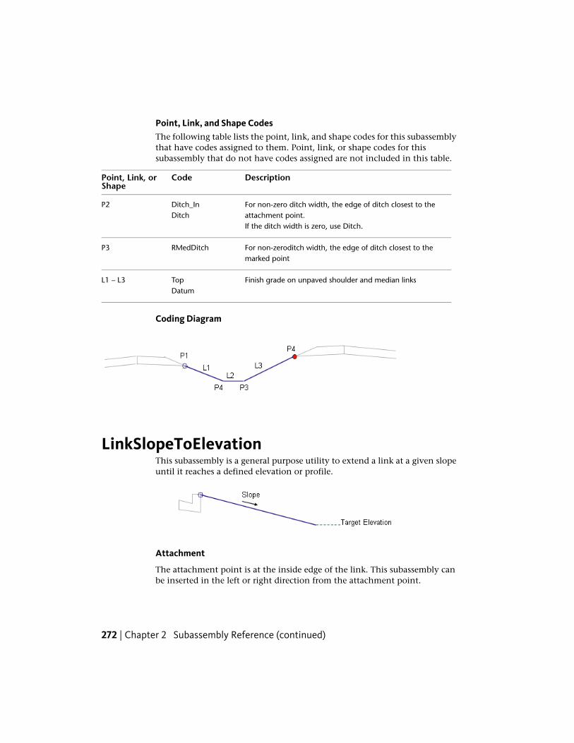
Point, Link, and Shape CodesThe following table lists the point, link, and shape codes for this subassemblythat have codes assigned to them. Point, link, or shape codes for thissubassembly that do not have codes assigned are not included in this table.
DescriptionCodePoint, Link, orShape
For non-zero ditch width, the edge of ditch closest to theattachment point.
Ditch_InDitch
P2
If the ditch width is zero, use Ditch.
For non-zeroditch width, the edge of ditch closest to themarked point
RMedDitchP3
Finish grade on unpaved shoulder and median linksTopL1 – L3Datum
Coding Diagram
LinkSlopeToElevationThis subassembly is a general purpose utility to extend a link at a given slopeuntil it reaches a defined elevation or profile.
Attachment
The attachment point is at the inside edge of the link. This subassembly canbe inserted in the left or right direction from the attachment point.
272 | Chapter 2 Subassembly Reference (continued)

Input ParametersNote: All dimensions are in meters or feet unless otherwise noted. All slopesare in run-over-rise form (for example, 4 : 1) unless indicated as a percentslope with a “%” sign.
DefaultTypeDescriptionParameter
RightLeft/RightSpecifies which side to place the sub-assembly
Side
2 (%), (or 2:1)Numeric, posit-ive
% or ratio slope of the link. Negativeslopes go downward in the direction inser-ted.
Slope
0.0NumericElevation value to extend the link to at thegiven slope
Target Elevation
P2Comma-separ-ated string
A list of surface codes to be assigned tothe outside edge of the link
Point Codes
Top, DatumComma-separ-ated string
A list of codes to be assigned to the linkLink Codes
NoYes\NoThis parameter adds or removes the sur-face link.
Omit Link
NoneSelection List:Specifies to use superelevation slope forthe shoulder
Use Superelevationa) OutsideShoulderSlope, b) In-side ShoulderSlope, c)Out-side Lane,d)Inside Lane,e) None
Target ParametersThis section lists the parameters in this subassembly that can be mapped toone or more target objects, such as a surface, alignment, or profile object in
LinkSlopeToElevation | 273

a drawing. For more information, see Setting Targets in the AutoCAD Civil3D User’s Guide Help.
StatusDescriptionParameter
OptionalMay be used to override the fixed Target Eleva-tion and tie the end-of-link to a profile. The fol-
Target Elevation
lowing object types can be used as targets forspecifying this elevation: profiles, 3D polylines,feature lines, or survey figures.
Output Parameters
TypeDescriptionParameter
Numeric+/- offset of the beginning of the linkBegin Offset
NumericElevation of the beginning of the linkBegin Elevation
Numeric+/- offset of the end of the linkEnd Offset
NumericElevation of the end of the linkEnd Elevation
Behavior
A link is added from the attachment point in the direction of insertion forthe given slope until it reaches the target elevation or profile. The slope valueis applied upward if the target elevation is above the attachment point,otherwise a negative slope is used.
This subassembly includes an optional input parameter named UseSuperelevation Slope that lets you specify to use the superelevation slope forthe shoulder. This parameter can be set to a) Outside shoulder slope, b) Insideshoulder slope, c)Outside Lane, d)Inside Lane, or e) None. None is the defaultsetting.
Layout Mode Operation
In layout mode, this subassembly displays the link at the given slope for ahorizontal distance of 3 meters or 10 feet.
274 | Chapter 2 Subassembly Reference (continued)

Point, Link, and Shape Codes
None.
Coding Diagram
LinkSlopeToSurfaceThis subassembly is a general purpose utility to extend a link from theattachment point at a given slope to the closest intersection with a targetsurface.
Attachment
The attachment point is at the beginning of the link.
LinkSlopeToSurface | 275

Input ParametersNote: All dimensions are in meters or feet unless otherwise noted. All slopesare in run-over-rise form (for example, 4 : 1) unless indicated as a percentslope with a “%” sign.
DefaultTypeDescriptionParameter
RightLeft/RightSpecifies which side to place the subassemblySide
NoneSelection List:Specifies to use superelevation slope for theshoulder
Use Superelev-ation a) Outside
Shoulder Slope,b) InsideShoulder Slope,c)Outside LaneSlope, d)InsideLane Slope, e)None
2 (%), (or 2:1)Numeric% slope of the linkSlope
Cut and FillSelection List:Specifies to add link in cut, fill, or cut and fillconditions
Add Link Ina) Cut and Fill, b)Cut Only, c) FillOnly
P2Comma-separ-ated string
A list of surface codes to be assigned to theoutside edge of the link
Point Codes
Top, DatumComma-separ-ated string
A list of codes to be assigned to the linkLink Codes
NoYes/NoThis parameter adds or removes the surfacelink
Omit Link
Target ParametersThis section lists the parameters in this subassembly that can be mapped toone or more target objects, such as a surface, alignment, or profile object in
276 | Chapter 2 Subassembly Reference (continued)

a drawing. For more information, see Setting Targets in the AutoCAD Civil3D User’s Guide Help.
StatusDescriptionParameter
RequiredName of the surface the link is tying to. The follow-ing object types can be used as targets for specify-ing this surface: surfaces.
Target Surface
Output Parameters
TypeDescriptionParameter
Numeric+/- offset of the beginning of the linkBegin Offset
NumericElevation of the beginning of the linkBegin Elevation
Numeric+/- offset of the end of the linkEnd Offset
NumericElevation of the end of the linkEnd Elevation
Behavior
A link is extended to the left or right from the attachment point at the givenslope until it intersects the target surface.
By default, a cut or fill link will be added from the attachment point to thetarget surface. If the link needs to be added only in cut or fill conditions,specify appropriately a value for the Add Link In property of the subassembly.If the cut link and fill links must be at different slopes, then add thissubassembly twice, at the same attachment point, once for Cut Only and thenagain for Fill Only conditions, with slopes as needed.
This subassembly includes an optional input parameter named UseSuperelevation Slope that lets you specify to use the superelevation slope forthe shoulder. This parameter can be set to a) Outside shoulder slope, b) Insideshoulder slope, c)Outside Lane Slope, d)Inside Lane Slope, or e) None. Noneis the default setting.
Layout Mode Operation
In layout mode, this subassembly attempts to find the intersection of the link,if the target surface was inserted by a previous subassembly. If an intersectionis found, the link is displayed at the given slope to the surface. If not, the link
LinkSlopeToSurface | 277

is displayed at the given slope outward for a horizontal distance of 3 metersor 10 feet, terminating in an arrowhead pointing outward.
Point, Link, and Shape CodesThe following table lists the point, link, and shape codes for this subassemblythat have codes assigned to them. Point, link, or shape codes for thissubassembly that do not have codes assigned are not included in this table.
DescriptionCodePoint, Link,or Shape
If the link is added in cut condition.Daylight_CutL1
If the link is added in fill condition.Daylight_FillL1
NOTE You can add other codes for points and links as needed using the inputparameters listed for this subassembly.
Coding Diagram
LinkToLaneMarkerThis subassembly is a general purpose utility to mark a point on a lanesubassembly from the attachment point to a specified width and slope.
278 | Chapter 2 Subassembly Reference (continued)
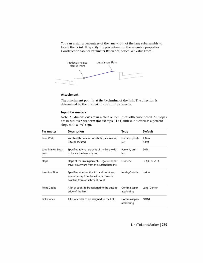
You can assign a percentage of the lane width of the lane subassembly tolocate the point. To specify the percentage, on the assembly propertiesConstruction tab, for Parameter Reference, select Get Value From.
Attachment
The attachment point is at the beginning of the link. The direction isdetermined by the Inside/Outside input parameter.
Input ParametersNote: All dimensions are in meters or feet unless otherwise noted. All slopesare in run-over-rise form (for example, 4 : 1) unless indicated as a percentslope with a “%” sign.
DefaultTypeDescriptionParameter
1.8 mNumeric, posit-ive
Width of the lane on which the lane markeris to be located
Lane Width6.0 ft
50%Percent, unit-less
Specifies at what percent of the lane widthto locate the lane marker
Lane Marker Loca-tion
-2 (%; or 2:1)NumericSlope of the link in percent. Negative slopestravel downward from the current baseline.
Slope
InsideInside/OutsideSpecifies whether the link and point arelocated away from baseline or towardsbaseline from attachment point
Insertion Side
Lane_CenterComma-separ-ated string
A list of codes to be assigned to the outsideedge of the link
Point Codes
NONEComma-separ-ated string
A list of codes to be assigned to the linkLink Codes
LinkToLaneMarker | 279

DefaultTypeDescriptionParameter
TrueTrue/FalseIf False, adds the link, the start point, andthe end point. If True, adds the end pointonly.
Omit Link
Target Parameters
None.
Output Parameters
TypeDescriptionParameter
NumericDistance between the insertion point and the lanemarker location
Link Width
NumericSlope of the link (negative if the slope travels downwardfrom the baseline outwards)
Link Slope
Numeric+/- offset of the beginning of the linkBegin Offset
NumericElevation of the beginning of the linkBegin Elevation
Numeric+/- offset of the end of the linkEnd Offset
NumericElevation of the end of the linkEnd Elevation
Behavior
A link is added from the attachment point to the specified width and slope,on the specified side. The width of the link is determined by multiplying theLane Width parameter by the Lane Marker Location parameter. At the otherend of the link, a point is added with the specified code.
You can specify the slope of the link as either a negative or positive value.Typically, the slope travels in the same direction as the lane slope. A typicallane slope is specified as -2% (a negative value), which indicates that thepavement travels downwards from the centerline.
For example, you can add a subassembly from the outside edge of the travelway towards the baseline to mark the midpoint of a lane subassembly, asshown in the image below. In this case: the Insertion Side value is Inside; theLane Width value is the typical lane width, which is specified using Get ValueFrom as the Parameter Reference value on the assembly properties Construction
280 | Chapter 2 Subassembly Reference (continued)

tab; the Lane Slope value is the typical lane slope, also specified using theParameter Reference setting; and Lane Marker Location is 50%.
The lane slope parameter from the previous subassembly is returned as -2%(assuming that is the slope of the lane subassembly). Since theLinkToLaneMarker subassembly is inserted inside, this slope value is multipliedby -1 (that is, the sign value is changed), which means the subassembly travelsupwards from the insertion point at the outside edge of the pavement.
If you want to mark a point on the lane relative to the inside edge of the travelway or to the Crown Point of a previous lane subassembly, then set theLinkToLaneMarker subassembly Insertion Side value to Outside. Again, theLane Width and Lane Slope values are assigned using Get Value From as theParameter Reference value, the Lane Marker Location is 50%, and the laneslope parameter from the previous subassembly is returned as -2% (assumingthat is the slope of the lane subassembly). Since the LinkToLaneMarkersubassembly is inserted outside, the slope value is used as is and thesubassembly travels downwards from the insertion point at the inside edgeof the pavement.
Layout Mode Operation
In layout mode, the subassembly displays the link calculated using the LaneWidth, Lane Marker Location, and Slope parameters. If the subassembly isadded to an assembly and the values are assigned using the Get Value Fromoption, then the link and the point are calculated based on the assigned lanesubassembly.
Point, Link, and Shape Codes
None.
Coding Diagram
LinkToLaneMarker | 281

LinkToMarkedPointThis subassembly is a general purpose utility to connect a link from theattachment point to a previously named marked point.
It can be used in a variety of situations, including connecting between adjacentroadways where the relative offsets and elevations vary, or across a gore areabetween converging roadways. Use the MarkPoint subassembly if theconnecting point has not already been named.
NOTE In order for the LinkToMarkedPoint subassembly to work (draw) properly,it must be located below the MarkedPoint subassembly on the Construction tabof the Assembly properties. If the LinkToMarkedPoint subassembly is not locatedbelow the MarkedPoint subassembly on the Construction tab, you should selectthe Subassembly Group name in the Construction tab, then right-click and chooseMove Up, so that the MarkedPoint subassembly is located above theLinkToMarkedPoint subassembly in the list.
Attachment
The attachment point is at the beginning of the link. The link may go in anydirection. The direction is determined by the location of the marked pointrelative to the attachment point. Be sure to name the marked point and setthe marked point name in this subassembly.
Input ParametersNote: All dimensions are in meters or feet unless otherwise noted. All slopesare in run-over-rise form (for example, 4 : 1) unless indicated as a percentslope with a “%” sign.
DefaultTypeDescriptionParameter
NoneStringName of the marked point to connect toMarked PointName
282 | Chapter 2 Subassembly Reference (continued)
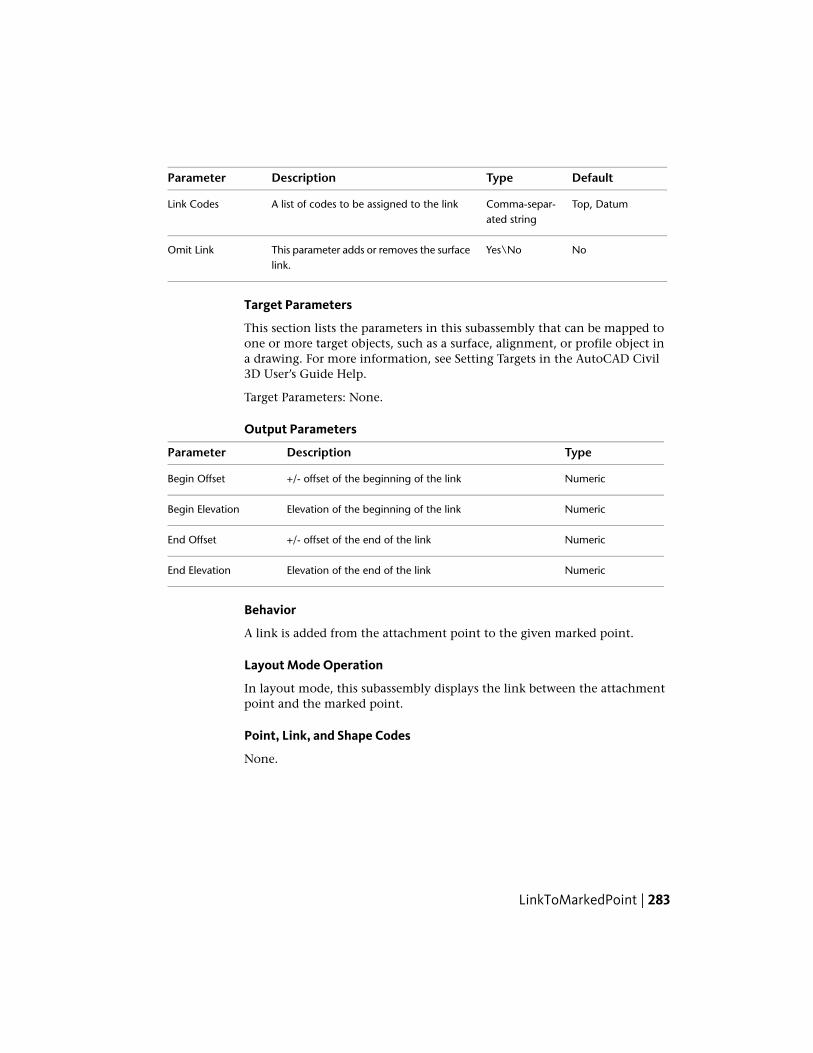
DefaultTypeDescriptionParameter
Top, DatumComma-separ-ated string
A list of codes to be assigned to the linkLink Codes
NoYes\NoThis parameter adds or removes the surfacelink.
Omit Link
Target Parameters
This section lists the parameters in this subassembly that can be mapped toone or more target objects, such as a surface, alignment, or profile object ina drawing. For more information, see Setting Targets in the AutoCAD Civil3D User’s Guide Help.
Target Parameters: None.
Output Parameters
TypeDescriptionParameter
Numeric+/- offset of the beginning of the linkBegin Offset
NumericElevation of the beginning of the linkBegin Elevation
Numeric+/- offset of the end of the linkEnd Offset
NumericElevation of the end of the linkEnd Elevation
Behavior
A link is added from the attachment point to the given marked point.
Layout Mode Operation
In layout mode, this subassembly displays the link between the attachmentpoint and the marked point.
Point, Link, and Shape Codes
None.
LinkToMarkedPoint | 283

Coding Diagram
LinkToMarkedPoint2This subassembly is a general purpose utility that is similar to theLinkToMarkedPoint subassembly, and connects a link from the attachmentpoint to a previously named marked point.
It can be used in a variety of situations, including connecting between adjacentroadways, where the relative offsets and elevations vary, or across a gore areabetween converging roadways. Use the MarkPoint subassembly if theconnecting point has not already been named.
NOTE The primary difference between the LinkToMarkedPoint2 subassembly andthe LinkToMarked point subassembly is in its application, when the marked pointis on a different assembly baseline comparing to the link. Particularly if the twobaselines in are not parallel, then the subassembly’s application will not be in thesame plane, making the length of the link to marked point longer than it shouldbe.
Attachment
The attachment point is at the beginning of the link. The link may go in anydirection. The direction is determined by the location of the marked pointrelative to the attachment point.
284 | Chapter 2 Subassembly Reference (continued)

Input ParametersNote: All dimensions are in meters or feet unless otherwise noted. All slopesare in run-over-rise form (for example, 4 : 1) unless indicated as a percentslope with a “%” sign.
DefaultTypeDescriptionParameter
NoneStringName of the marked point to connect toMarked PointName
Top, DatumComma-separ-ated string
A list of codes to be assigned to the linkLink Codes
NoTrue\FalseThis parameter adds or removes the surfacelink. False to add the link, the start point,
Omit Link
and the end point. True to add the endpoint only.
Target Parameters
This section lists the parameters in this subassembly that can be mapped toone or more target objects, such as a surface, alignment, or profile object ina drawing. For more information, see Setting Targets in the AutoCAD Civil3D User’s Guide Help.
Target Parameters: None.
Output Parameters
TypeDescriptionParameter
Numeric+/- offset of the beginning of the linkBegin Offset
NumericElevation of the beginning of the linkBegin Elevation
Numeric+/- offset of the end of the linkEnd Offset
NumericElevation of the end of the linkEnd Elevation
Behavior
The following diagram illustrates how the LinkToMarkedPoint2 subassemblyfunctions, as well as how it displays in a cross-section for the offset baselineportion of the corridor.
LinkToMarkedPoint2 | 285

The LinkToMarkedPoint2 subassembly should do either of the following, bothof which have the same result:
■ Project point #7 onto line beta, resulting in point #6. Then compute thedistance from #4 to #6. This would be the marked point distance.
■ Project point #4 orthogonally from line beta onto line alpha, resulting inpoint #5. Then compute the distance from #5 to #7, and multiple by cosine(angle gamma). This would also be the link-to-marked-point distance.
Note that the new LinkToMarkedPoint2 subassembly should not rely on thefact that point #7 will be at a constant offset at all stations along the mainalignment.
Offset Baseline Corridor Cross-Section
Note the following:
■ The cross-section sample line is orthogonal to the main baseline at point#8 (line alpha).
■ The cross-section sample line is composed of one or more segments, withall segments collinear.
■ The corridor point data for the offset portion of the corridor has offsetvalues stored relative to the offset baseline.
■ To project this corridor point data in the cross-section from line beta toline alpha for display in the cross-section view, the offset will need to bedivided by cosine (angle gamma).
Note that using this approach, a lane subassembly on the offset portion ofthe corridor that is defined to be 3.5 meters in width, will be slightly widerthan 3.5 meters in width when shown in the corridor cross-section.
Layout Mode Operation
In layout mode, this subassembly displays the link between the attachmentpoint and the marked point.
Point, Link, and Shape Codes
None.
286 | Chapter 2 Subassembly Reference (continued)

Coding Diagram
LinkVerticalThis subassembly is a general purpose utility to add a vertical surface link byvertical deflection.
A profile can be used when building a corridor model to allow variable verticaldeflection.
Attachment
The attachment point is at the inside edge of the link. This subassembly canbe inserted in the left or right direction from the attachment point.
Input ParametersNote: All dimensions are in meters or feet unless otherwise noted. All slopesare in run-over-rise form (for example, 4 : 1) unless indicated as a percentslope with a “%” sign.
DefaultTypeDescriptionParameter
3.0 mNumeric+/- vertical deflection from the attachment point.Negative deflections are downward.
Vertical Deflection10.0 ft
P2Comma-separ-ated string
A list of surface codes to be assigned to the out-side edge of the link
Point Codes
LinkVertical | 287

DefaultTypeDescriptionParameter
Top, DatumComma-separ-ated string
A list of codes to be assigned to the linkLink Codes
NoYes\NoThis parameter adds or removes the surface link.Omit Link
Target ParametersThis section lists the parameters in this subassembly that can be mapped toone or more target objects, such as a surface, alignment, or profile object ina drawing. For more information, see Setting Targets in the AutoCAD Civil3D User’s Guide Help.
StatusDescriptionParameter
OptionalMay be used to override the fixed Vertical Deflectionand tie the end-of-link to a profile. The following ob-
Vertical Deflection
ject types can be used as targets for specifying this:profiles, 3D polylines, feature lines, or survey figures.
Output Parameters
TypeDescriptionParameter
Numeric+/- offset of the beginning of the linkBegin Offset
NumericElevation of the beginning of the linkBegin Elevation
NumericElevation of the end of the linkEnd Elevation
Behavior
A vertical link is added from the attachment point for the given verticaldeflection. If a profile name is given for the Vertical Deflection, the end ofthe link will match the profile elevation.
Layout Mode Operation
In layout mode, this subassembly displays the link for the given +/- verticaldeflection.
Point, Link, and Shape Codes
None.
288 | Chapter 2 Subassembly Reference (continued)

Coding Diagram
LinkWidthAndSlopeThis subassembly is a general purpose utility to add a surface link by specifyingits width and slope.
Either a % slope or ratio slope value may be given. An alignment or profilecan be used when building a corridor model to allow variable width and slope.
Attachment
The attachment point is at the inside edge of the link. This subassembly canbe inserted in the left or right direction from the attachment point.
Input ParametersNote: All dimensions are in meters or feet unless otherwise noted. All slopesare in run-over-rise form (for example, 4 : 1) unless indicated as a percentslope with a “%” sign.
DefaultTypeDescriptionParameter
LeftLeft/RightSpecifies which side to place the subassemblySide
3.0Numeric, posit-ive
Width of the lane from the offset of the inside edgeto the offset of the outside edge
Width10.0 ft
LinkWidthAndSlope | 289

DefaultTypeDescriptionParameter
2 (%), (or2:1)
Numeric% slope of the link. Negative slopes go downward inthe direction inserted.
Slope
P2Comma-separ-ated string
A list of surface codes to be assigned to the outsideedge of the link
Point Codes
Top,Datum
Comma-separ-ated string
A list of surface codes to be assigned to the linkLink Codes
NoYes\NoThis parameter adds or removes the surface link.Omit Link
NoneSelection List:Specifies to use superelevation slope for the shoulderUse Superelev-ation a) Outside
Shoulder Slope,b) InsideShoulder Slope,c)Outside Lane,d)Inside Lane,e) None
Target ParametersThis section lists the parameters in this subassembly that can be mapped toone or more target objects, such as a surface, alignment, or profile object ina drawing. For more information, see Setting Targets in the AutoCAD Civil3D User’s Guide Help.
StatusDescriptionParameter
OptionalMay be used to override the fixed link Width and tiethe end-of-link to an offset alignment. The following
Width
object types can be used as targets for specifying thisoffset: alignments, polylines, feature lines, or surveyfigures.
OptionalMay be used to override the fixed % Slope and tie theend-of-link to a profile. The following object types can
%Slope
be used as targets for specifying this: profiles, 3Dpolylines, feature lines, or survey figures.
290 | Chapter 2 Subassembly Reference (continued)

Output Parameters
TypeDescriptionParameter
Numeric+/- offset of the beginning of the linkBegin Offset
NumericElevation of the beginning of the linkBegin Elevation
Numeric+/- offset of the end of the linkEnd Offset
NumericElevation of the end of the linkEnd Elevation
Behavior
The link is added in the direction of insertion starting at the attachment pointand going the given width and slope. If an offset horizontal alignment nameis assigned to the Width during corridor modeling, the width of the lane willvary to match the offset of the alignment. If a profile name is assigned to theSlope, the slope is adjusted to match the profile elevation at the end of thelink.
This subassembly includes an optional input parameter named UseSuperelevation Slope that lets you specify to use the superelevation slope forthe shoulder. This parameter can be set to a) Outside shoulder slope, b) Insideshoulder slope, c)Outside Lane, d)Inside Lane, or e) None. None is the defaultsetting.
Layout Mode Operation
In layout mode, this subassembly displays the link at the given width andslope.
Point, Link, and Shape Codes
None.
Coding Diagram
LinkWidthAndSlope | 291

LotGradeThis subassembly is used to grade lots from a right of way line.
The following illustration shows an example of this subassembly being usedwhen the target profile elevation at the back of the lot is higher than theattachment point.
The following illustration shows an example of this subassembly being usedwhen the attachment point is higher than the target profile elevation at theback of the lot.
Attachment
The attachment point is at the inside edge of the lane on the finished grade.
292 | Chapter 2 Subassembly Reference (continued)

Input ParametersNote: All dimensions are in meters or feet unless otherwise noted. All slopesare in run-over-rise form (for example, 4 : 1) unless indicated as a percentslope with a “%” sign.
DefaultTypeDescriptionParameter
RightLeft \ RightIndicates which side the subassembly is inserted to-wards.
Side
3.6 mNumeric,positive
The inside width of the lot.Inside Width12.0 ft
3.6 mNumeric,positive
The outside width of the lot.Outside Width12.0 ft
1 %Numeric,positive
The minimum slope for the outside width of the lot.Min Slope
Target ParametersThis section lists the parameters in this subassembly that can be mapped toone or more target objects, such as a surface, alignment, or profile object ina drawing. For more information, see Setting Targets in the AutoCAD Civil3D User’s Guide Help.
StatusDescriptionParameter
OptionalMay be used to override the fixed Inside Width bytying the mid lot line to an offset alignment. The
Middle Offset
following object types can be used as targets forspecifying this offset: alignments, polylines, featurelines, or survey figures.
OptionalMay be used to override the fixed Outside Width bytying end lot line to an offset alignment. The follow-
Edge Offset
ing object types can be used as targets for specifyingthis offset: alignments, polylines, feature lines, orsurvey figures.
RequiredMay be used to override the fixed Elevation by tyingend lot line to an elevation. The following object
Edge Elevation
types can be used as targets for specifying this elev-
LotGrade | 293

StatusDescriptionParameter
ation: profiles, 3D polylines, feature lines, or surveyfigures.
Output Parameters
None.
Behavior
The lot grade assembly tool needs to start at the right of way and, much likethe BasicLaneTransition subassembly, it will hold grade and change offset tothe middle of the lot at a default slope of 1%. The value of the slope can beinput by the user. At the middle of the lot will be an alignment with no profile.So the assembly will be a link from right of way to that mid lot alignment at1% slope. Then the mid lot alignment will link to the back of lot, which is afixed elevation; for example, 74.00 feet. We need to maintain a minimumslope of 1% on the back half of the lot as well. Therefore there needs to be arule in place if the front of the lot grade at 1% slope does not allow for aminimum slope of 1% for the back half of the lot, then the back half of thelot grade needs to change to 1% and the front half lot grade needs to go steeper.
Layout Mode Operation
In layout mode, this subassembly draws the lane using the input parametervalues. It will use 1% as the steeper slope value.
Point, Link, and Shape CodesThe following table lists the point, link, and shape codes for this subassemblythat have codes assigned to them. Point, link, or shape codes for thissubassembly that do not have codes assigned are not included in this table.
DescriptionCodePoint, Link,or Shape
Crown of road on finished grade.CrownP1
Lot hinge point.HingeP2
Finish grade.TopL1, L2
294 | Chapter 2 Subassembly Reference (continued)

Coding Diagram
MarkPointThis subassembly is used to mark an existing point on the assembly with aname.
This is usually done so that other subassemblies can later insert links thatattach back to this point (for example, LinkToMarkedPoint). The attachmentpoint is the point that is marked. You can add user-defined point codes tothis marked point.
In the example below, there are two roadways with independent profiles.Once the links for the first roadway are created, the point at the left outsideedge is being marked. Later, after the links for the second roadway are created,a link can be inserted from its right outside edge back to the marked point.
NOTE If you use the MarkPoint subassembly with the LinkToMarkedPointsubassembly, in order for the LinkToMarkedPoint subassembly to work (draw)properly, it must be located below the MarkedPoint subassembly on theConstruction tab of the Assembly properties. If the LinkToMarkedPoint subassemblyis not located below the MarkedPoint subassembly on the Construction tab, youshould select the Subassembly Group name in the Construction tab, then right-clickand choose Move Up, so that the MarkedPoint subassembly is located above theLinkToMarkedPoint subassembly in the list.
Attachment
The marked point name is placed at the attachment point.
MarkPoint | 295
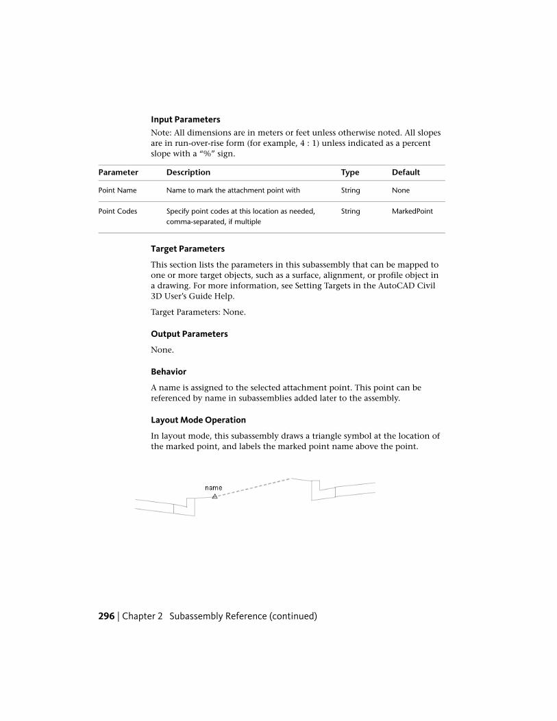
Input ParametersNote: All dimensions are in meters or feet unless otherwise noted. All slopesare in run-over-rise form (for example, 4 : 1) unless indicated as a percentslope with a “%” sign.
DefaultTypeDescriptionParameter
NoneStringName to mark the attachment point withPoint Name
MarkedPointStringSpecify point codes at this location as needed,comma-separated, if multiple
Point Codes
Target Parameters
This section lists the parameters in this subassembly that can be mapped toone or more target objects, such as a surface, alignment, or profile object ina drawing. For more information, see Setting Targets in the AutoCAD Civil3D User’s Guide Help.
Target Parameters: None.
Output Parameters
None.
Behavior
A name is assigned to the selected attachment point. This point can bereferenced by name in subassemblies added later to the assembly.
Layout Mode Operation
In layout mode, this subassembly draws a triangle symbol at the location ofthe marked point, and labels the marked point name above the point.
296 | Chapter 2 Subassembly Reference (continued)

Point, Link, and Shape CodesThe following table lists the point, link, and shape codes for this subassemblythat have codes assigned to them. Point, link, or shape codes for thissubassembly that do not have codes assigned are not included in this table.
DescriptionCodePoint, Link,or Shape
Marked point codeMarkedPointP1
Coding Diagram
None.
MedianConstantSlopeWithBarrierThis subassembly is used to insert a median at the centerline, withasymmetrical barriers on either side of the centerline, and a tapered bottomwith an optional key.
The pavement structure follows the standards described in “Pavement Structureof Paved Sections" in the AutoCAD Civil 3D Help.
MedianConstantSlopeWithBarrier | 297

Attachment
The attachment point is at the middle of the median. The median is placedon either side with appropriate components as specified by the inputparameters.
Input Parameters
Note: All dimensions are in meters or feet unless otherwise noted. All slopesare in run-over-rise form (for example, 4 : 1) unless indicated as a percentslope with a “%” sign.
DefaultTypeDescriptionParameter
2.0mNumeric, positiveWidth of the median to the left of at-tachment point, including barrier area
Left Median Width6.0 ft
2.0mNumeric, positiveWidth of the median to the right of at-tachment point, including barrier area
Right Median Width6.0 ft
NoYes/NoSpecifies that attachment point will becoded as Crown
Crown Point at Center
0%NumericCross slope of the median to the left ofattachment point
Left Median CrossSlope
0%NumericCross slope of the median to the rightof attachment point
Right Median Slope
Both SidesString: (a) None, (b)Both Sides,(c) Right(d) Left
Specifies to place barriers on left and/orright sides
Barrier Option
298 | Chapter 2 Subassembly Reference (continued)

DefaultTypeDescriptionParameter
0.15 mNumeric, positiveWidth of the top of the barrierBarrier Top Width0.5 ft
0.225 mNumeric, positiveWidth of the middle of the barrierBarrier Middle Width0.75 ft
0.075 mNumeric, positiveHeight of the curb at the bottom ofbarrier
Curb Height0.25 ft
0.6 mNumeric, positiveWidth of the bottom of the barrierBarrier Bottom Width2.0 ft
0.9 mNumeric, positiveHeight to the top of the barrierBarrier Height3.0 ft
0.45 mNumeric, positiveHeight to the middle of the barrierBarrier Middle Height1.5 ft
0.015 mNumericDifference in the median edge pointelevation with respect to edge of pavedshoulder
Shoulder Height Offset0.05 ft
1.2 mNumeric, PositiveWidth from the left shoulder from in-side edge of pavement to median start
Left Shoulder Width4.0 ft
point. Zero value can be entered if noshoulder is needed on the left side.
-2%Numeric, PositiveDefault cross slope of the shoulder sur-face. This value is used if superelevation
Left Shoulder DefaultSlope
slope is not used, or is not specified forthe baseline alignment.
Insideshoulder slope
String: List of op-tions: a.) No, b.)
Specifies to use the slope from the su-perelevation specification defined onthe baseline alignment
Left Shoulder - UseSuperelevation Slope
Outside shoulderslope, c.) Insideshoulder slope
1.2 mNumeric, PositiveWidth from the right shoulder from in-side edge of pavement to median start
Right Shoulder Width4.0 ft
MedianConstantSlopeWithBarrier | 299

DefaultTypeDescriptionParameter
point. Zero value can be entered if noshoulder is needed on the right side.
-2%Numeric, PositiveDefault cross slope of the right shouldersurface. This value is used if supereleva-
Right Shoulder DefaultSlope
tion slope is not used, or is not spe-cified for the baseline alignment.
Insideshoulder slope
String: List of op-tions: a.) No, b.)
Specifies to use the slope from the su-perelevation specification defined onthe baseline alignment.
Right Shoulder - UseSuperelevation Slope
Outside shoulderslope, c.) Insideshoulder slope
-4%NumericCross slope of subbase from each endtowards middle. If optional drain keyis selected, then it is to that point.
Subbase Slope
Below RightBarrier
String; (a) None, (b)Below Left Barrier,
Specifies to add drain key below oneof the barriers.
Drain Key
(c) Below Right Bar-rier
0.3 mNumeric, positiveWidth of the optional key bottomKey Width1.0 ft
0.3 mNumeric, positiveDepth of the optional key on the shortside
Key Depth1.0 ft
0.025 mNumeric, positiveDepth between finish grade and Pave1for the left shoulder
Left Pave1 Depth0.083 ft
0.025 mNumeric, positiveDepth second level pavement materialfor the left shoulder
Left Pave2 Depth0.083ft
0.100 mNumeric, positiveDepth of base course (between Pave2and Base) for the left shoulder
Left Base Depth0.333 ft
0.300 mNumericDepth of the subbase layer at the leftinside edge of pavement (start of the
Left Subbase Depth1.0 ft
left shoulder). If shoulder width is set
300 | Chapter 2 Subassembly Reference (continued)
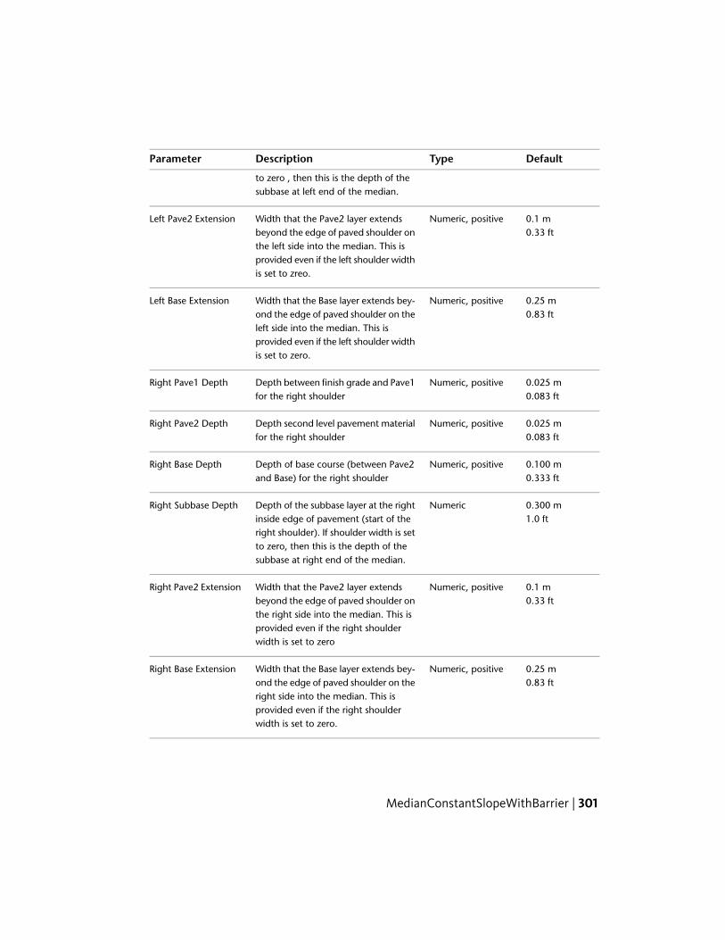
DefaultTypeDescriptionParameter
to zero , then this is the depth of thesubbase at left end of the median.
0.1 mNumeric, positiveWidth that the Pave2 layer extendsbeyond the edge of paved shoulder on
Left Pave2 Extension0.33 ft
the left side into the median. This isprovided even if the left shoulder widthis set to zreo.
0.25 mNumeric, positiveWidth that the Base layer extends bey-ond the edge of paved shoulder on the
Left Base Extension0.83 ft
left side into the median. This isprovided even if the left shoulder widthis set to zero.
0.025 mNumeric, positiveDepth between finish grade and Pave1for the right shoulder
Right Pave1 Depth0.083 ft
0.025 mNumeric, positiveDepth second level pavement materialfor the right shoulder
Right Pave2 Depth0.083 ft
0.100 mNumeric, positiveDepth of base course (between Pave2and Base) for the right shoulder
Right Base Depth0.333 ft
0.300 mNumericDepth of the subbase layer at the rightinside edge of pavement (start of the
Right Subbase Depth1.0 ft
right shoulder). If shoulder width is setto zero, then this is the depth of thesubbase at right end of the median.
0.1 mNumeric, positiveWidth that the Pave2 layer extendsbeyond the edge of paved shoulder on
Right Pave2 Extension0.33 ft
the right side into the median. This isprovided even if the right shoulderwidth is set to zero
0.25 mNumeric, positiveWidth that the Base layer extends bey-ond the edge of paved shoulder on the
Right Base Extension0.83 ft
right side into the median. This isprovided even if the right shoulderwidth is set to zero.
MedianConstantSlopeWithBarrier | 301

Target ParametersThis section lists the parameters in this subassembly that can be mapped toone or more target objects, such as a surface, alignment, or profile object ina drawing. For more information, see Setting Targets in the AutoCAD Civil3D User’s Guide Help.
StatusDescriptionParameter
OptionalMay be used to override the fixed Shoulder Width onthe left side and tie the inside edge-of-shoulder to an
Left PavedShoulder Width
offset alignment. The following object types can be usedas targets for specifying this offset: alignments, polylines,feature lines, or survey figures.
OptionalMay be used to override the fixed Shoulder Width onthe right side and tie the inside edge-of-shoulder to an
Right PavedShoulder Width
offset alignment. The following object types can be usedas targets for specifying this offset: alignments, polylines,feature lines, or survey figures.
Output Parameters
TypeDescriptionParameter
Numeric, positiveHeight to the top of the barrier.Barrier Height
Numeric, positiveSlope of the left paved shoulder.Left Shoulder Slope
Numeric, positiveSlope of the right paved shoulder.Right Shoulder Slope
NumericDepth of the median at the deepest point, near the op-tional key location.
Median MaximumDepth
Behavior
This subassembly is inserted on both sides of attachment point, starting withthe median links, using left/right median widths and other parameters. Edgeof paved shoulder will be located (on both right and left sides) using ShoulderHeight Offset parameter value. The finish grade of the shoulder is inserted forthe given Shoulder Width and Shoulder Slope outward from the attachmentpoint. The subbase link is inserted from the outer most point on the pavedshoulders starting at the “Subbase Depth”, for left and right sides respectively,below the finish grade.
302 | Chapter 2 Subassembly Reference (continued)

The Pave1, Pave2, and Base surface links are inserted parallel to the finishgrade at the given depths. If the layer Extension values are non-zero, eachlayer is extended for the given distance beyond the shoulder hinge point.Each layer should be as wide as or wider than the one above it.
Finally, Barrier links are added from the end of the medians using the barrierbottom width, height, middle width, middle height and curb heightparameters.
Layout Mode Operation
In layout mode this subassembly displays all links using the default values forvarious input parameters.
Point, Link, and Shape CodesThe following table lists the point, link, and shape codes for this subassemblythat have codes assigned to them. Point, link, or shape codes for thissubassembly that do not have codes assigned are not included in this table.
DescriptionCodesType
Insertion point and typically at the centerlineCrownP1
Edge of paved shoulder on top linksEPSP2, P3
Edge of medianMedianP4, P5
Edge of paved shoulder on Pave1EPS_Pave1P6, P7
Edge of paved shoulder on Pave2EPS_Pave2P10, P11
Edge of paved shoulder on BaseEPS_BaseP14, P15
Top link on the median portion including barriersTopL1, L2, L17,L18
Barrier LinksBarrierL3-L7; L19-L23
Top, PaveL8, L24
Bottom of first pavement layerPave1L9, L25
Bottom of second pavement layerPave2L10, L26
MedianConstantSlopeWithBarrier | 303

DescriptionCodesType
Bottom of base course layerBaseL11, L27
Bottom of subbase course layerSubbaseL12, L14, L16
Pave1S1
Pave2S2
BaseS3
SubbaseS4
BarrierS5
304 | Chapter 2 Subassembly Reference (continued)
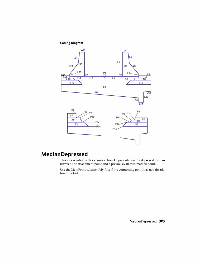
Coding Diagram
MedianDepressedThis subassembly creates a cross-sectional representation of a depressed medianbetween the attachment point and a previously named marked point.
Use the MarkPoint subassembly first if the connecting point has not alreadybeen marked.
MedianDepressed | 305

Attachment
The attachment point is at the outside edge of either the left or right medianditch slope, and the previously defined marked point must be on the oppositeoutside edge. It does not matter which point is left or right of the other.
Input ParametersNote: All dimensions are in meters or feet unless otherwise noted. All slopesare in run-over-rise form (for example, 4 : 1) unless indicated as a percentslope with a “%” sign.
DefaultTypeDescriptionParameter
NoneStringName of the previously defined marked pointMarked PointName
-4 ( : 1)NumericSlope (x : 1) of the link extending inward fromthe attachment point
Slope 1
-4 ( : 1)NumericSlope (x : 1) of the link extending inward fromthe marked point
Slope 2
Hold ditchsideslopes,
Selection listFor the cases where the top-of-ditch-slopepoints are at unequal elevations, selects
Hold DitchSlopes
shift ditchfrom center
whether to hold the ditch sideslopes and letthe position of the ditch shift, or to hold theditch at the center and adjust the sideslope onthe high side.
0.6 mNumeric, positiveWidth of the bottom of the median ditch (zerofor a V-ditch)
Ditch Width2 ft
306 | Chapter 2 Subassembly Reference (continued)

Target Parameters
This section lists the parameters in this subassembly that can be mapped toone or more target objects, such as a surface, alignment, or profile object ina drawing. For more information, see Setting Targets in the AutoCAD Civil3D User’s Guide Help.
Target Parameters: None.
Output Parameters
None.
Behavior
The locations of the attachment point and marked point are determined. Themarked point may be either to the right or left of the attachment point. Linksare extended inward at Slope 1 from the attachment point, and at Slope 2from the marked point, until they intersect. If a ditch width is given, ahorizontal bottom-of-ditch link is fit into the intersecting side slopes.
Ditch Slopes
The top of the ditch slopes may be at different elevations on the left and rightsides, resulting in an asymmetrical ditch. There are two options for handlingthis situation. If Hold Ditch Slopes is set to True, then the Slope 1 and Slope2 values are held on both sides, shifting the bottom of ditch away from thecenterline towards the lower side. If set to False, the ditch bottom is centeredabout the midpoint offset between the tops-of-slopes, the given slope is heldon the lower side, and the slope is adjusted to match on the higher side.
MedianDepressed | 307
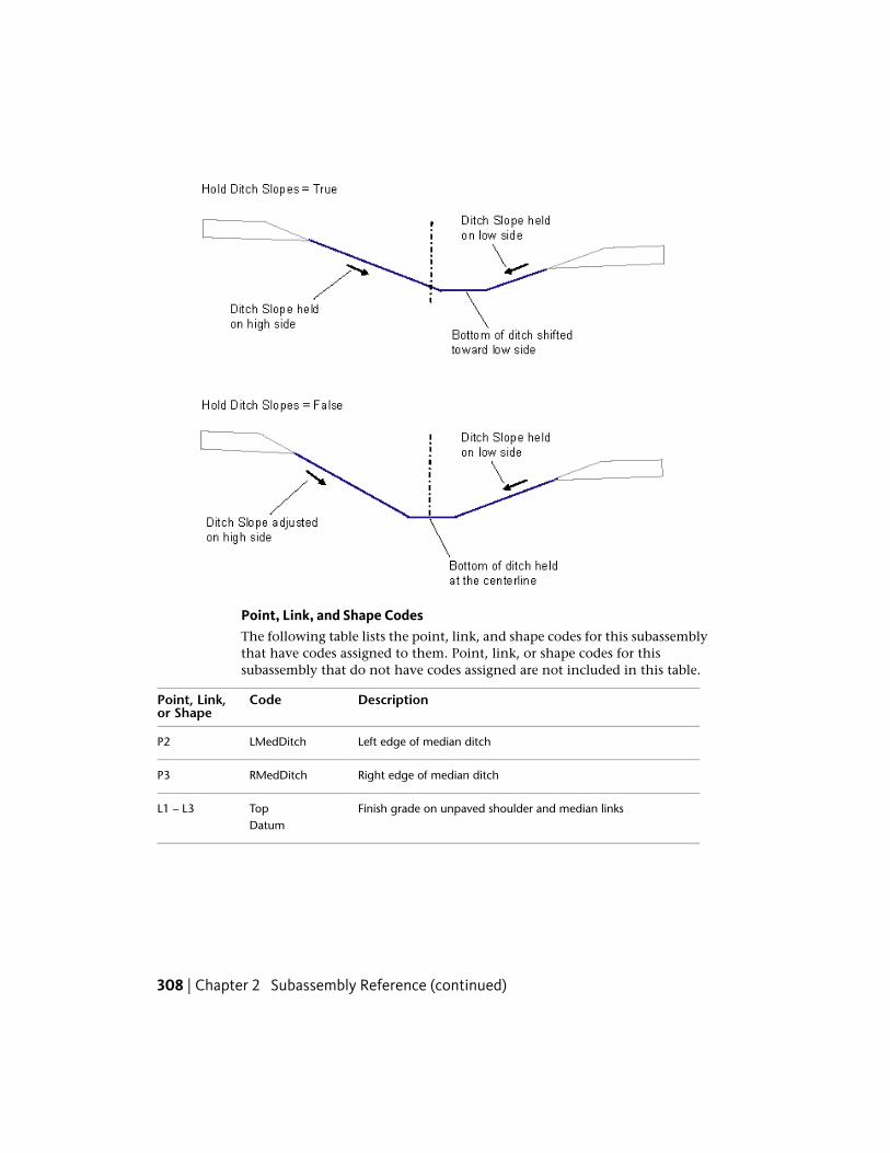
Point, Link, and Shape CodesThe following table lists the point, link, and shape codes for this subassemblythat have codes assigned to them. Point, link, or shape codes for thissubassembly that do not have codes assigned are not included in this table.
DescriptionCodePoint, Link,or Shape
Left edge of median ditchLMedDitchP2
Right edge of median ditchRMedDitchP3
Finish grade on unpaved shoulder and median linksTopL1 – L3Datum
308 | Chapter 2 Subassembly Reference (continued)

Layout Mode Operation
In layout mode, this subassembly calculates and displays the median linksbased on the input parameters given and the relative locations of theattachment point and marked point.
Coding Diagram
MedianDepressedShoulderExtThis subassembly creates a cross-sectional representation of a depressed medianwith inside shoulders, using extended termination of shoulder subbase.
It supports superelevation pivoting about the attachment point at thecenterline, or about the attachment point elevation at the insideedges-of-traveled-way. The pavement structure on the paved portions of theshoulder follows the standards described in "Pavement Structure of PavedSections" in the AutoCAD Civil 3D Help.
MedianDepressedShoulderExt | 309

Attachment
The attachment point is above the centerline of the ditch. The location of themedian links relative to the attachment point varies depending on the pivotmethod, and in some cases, the median widths and lane slopes. The attachmentpoint is typically placed on the baseline alignment at the design profileelevation.
310 | Chapter 2 Subassembly Reference (continued)

Input ParametersNote: All dimensions are in meters or feet unless otherwise noted. All slopesare in run-over-rise form (for example, 4 : 1) unless indicated as a percentslope with a “%” sign.
DefaultTypeDescriptionParameter
0.6 mNumeric,positive
Width of the bottom of the median ditch (zero fora V-ditch)
Ditch Width2 ft
4 : 1Numeric,positive
Inward slope from the shoulders toward the bottomof ditch (x : 1)
Ditch Slope
Hold ditchsideslopes,
Selectionlist
For the cases where the top-of-ditch-slope pointsare at unequal elevations, selects whether to hold
Hold Ditch Slopes
shift ditchthe ditch sideslopes and let the position of the ditchfrom cen-ter
shift, or to hold the ditch at the center and adjustthe sideslope on the high side
Pivotaboutcenterline
Selectionlist
Select whether the profile grade and pivot point isat the centerline above the median ditch, or if it isheld at the inside edges-of-traveled-ways
Centerline Pivot?
6.6 mNumeric,positive
Width from the median centerline to the left insideedge-of-traveled-way
Left Median Width22 ft
6.6 mNumeric,positive
Width from the median centerline to the right in-side edge-of-traveled-way
Right Median Width22 ft
0.6 mNumeric,positive
Width of the paved inside shoulderPaved ShoulderWidth 2.0 ft
0.0Numeric,positive
Width that the Pave1 layer extends beyond theedge-of-shoulder. The bottom of the Pave1 layermay not extend beyond the ditch sideslope.
Pave1 Extension
0.0Numeric,positive
Width that the Pave2 layer extends beyond theedge-of-shoulder. This should be equal to or
Pave2 Extension
greater than the Pave1 extension. The bottom ofthe Pave2 layer may not extend beyond the ditchsideslope.
MedianDepressedShoulderExt | 311
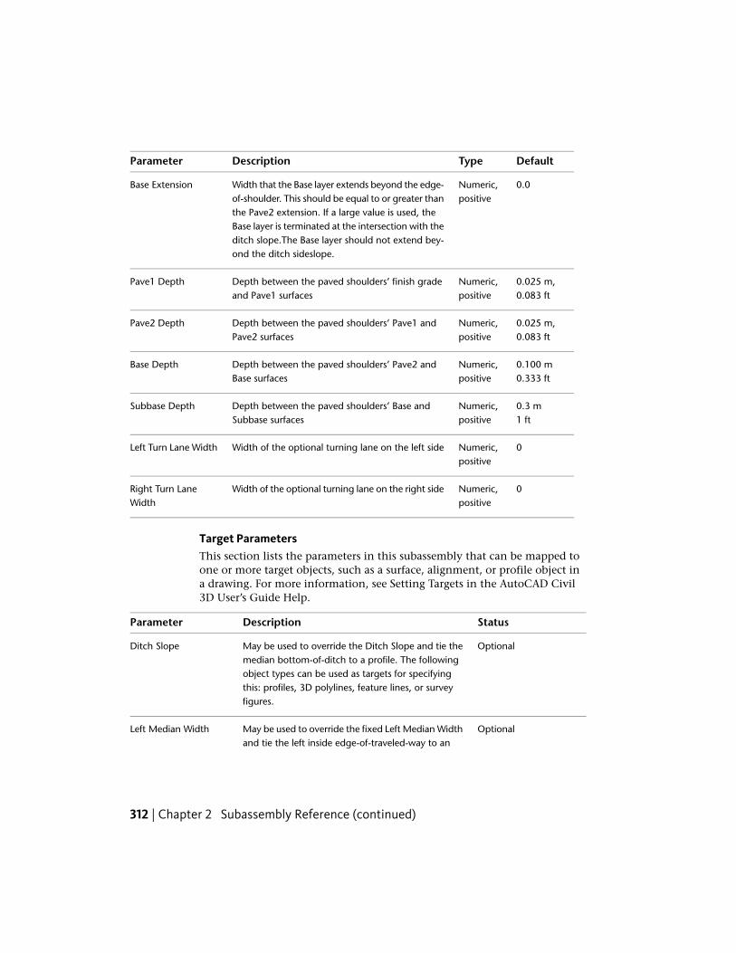
DefaultTypeDescriptionParameter
0.0Numeric,positive
Width that the Base layer extends beyond the edge-of-shoulder. This should be equal to or greater than
Base Extension
the Pave2 extension. If a large value is used, theBase layer is terminated at the intersection with theditch slope.The Base layer should not extend bey-ond the ditch sideslope.
0.025 m,Numeric,positive
Depth between the paved shoulders’ finish gradeand Pave1 surfaces
Pave1 Depth0.083 ft
0.025 m,Numeric,positive
Depth between the paved shoulders’ Pave1 andPave2 surfaces
Pave2 Depth0.083 ft
0.100 mNumeric,positive
Depth between the paved shoulders’ Pave2 andBase surfaces
Base Depth0.333 ft
0.3 mNumeric,positive
Depth between the paved shoulders’ Base andSubbase surfaces
Subbase Depth1 ft
0Numeric,positive
Width of the optional turning lane on the left sideLeft Turn Lane Width
0Numeric,positive
Width of the optional turning lane on the right sideRight Turn LaneWidth
Target ParametersThis section lists the parameters in this subassembly that can be mapped toone or more target objects, such as a surface, alignment, or profile object ina drawing. For more information, see Setting Targets in the AutoCAD Civil3D User’s Guide Help.
StatusDescriptionParameter
OptionalMay be used to override the Ditch Slope and tie themedian bottom-of-ditch to a profile. The following
Ditch Slope
object types can be used as targets for specifyingthis: profiles, 3D polylines, feature lines, or surveyfigures.
OptionalMay be used to override the fixed Left Median Widthand tie the left inside edge-of-traveled-way to an
Left Median Width
312 | Chapter 2 Subassembly Reference (continued)

StatusDescriptionParameter
offset alignment. The following object types can beused as targets for specifying this offset: alignments,polylines, feature lines, or survey figures.
OptionalMay be used to ovrride the fixed Right Median Widthand tie the right inside edge-of-traveled-way to an
Right Median Width
offset alignment. The following object types can beused as targets for specifying this offset: alignments,polylines, feature lines, or survey figures.
Output Parameters
None.
Behavior
This subassembly cannot be inserted separately for the left and right sides. Itbuilds the median to both sides of the attachment point.
Superelevation Pivot Point
The median can be configured to have the pivot point at the centerline, or atthe inside edges of traveled ways. If Centerline Pivot is used, the left and rightoutside lane superelevation slopes are obtained from the baseline’ssuperelevation specifications, and the elevations of the insideedges-of-traveled-ways are calculated by applying these slopes to the left andright median widths from the attachment point. If Centerline Pivot is notused, the edges-of-traveled-ways are held to the elevation of the attachmentpoint.
Ditch Elevations and Slopes
Superelevation or turning lanes may cause the top of the ditch slopes to be atdifferent elevations on the left and right sides, resulting in an asymmetricalditch. There are two options for handling this situation. If Hold Ditch Slopesis set to True, then the given ditch slopes are held constant on both sides,which shifts the bottom of ditch away from the centerline towards the lowerside. If set to False, the ditch bottom is centered about the median centerline,the given slope is held on the lower side, and the slope is adjusted to matchon the higher side.
MedianDepressedShoulderExt | 313
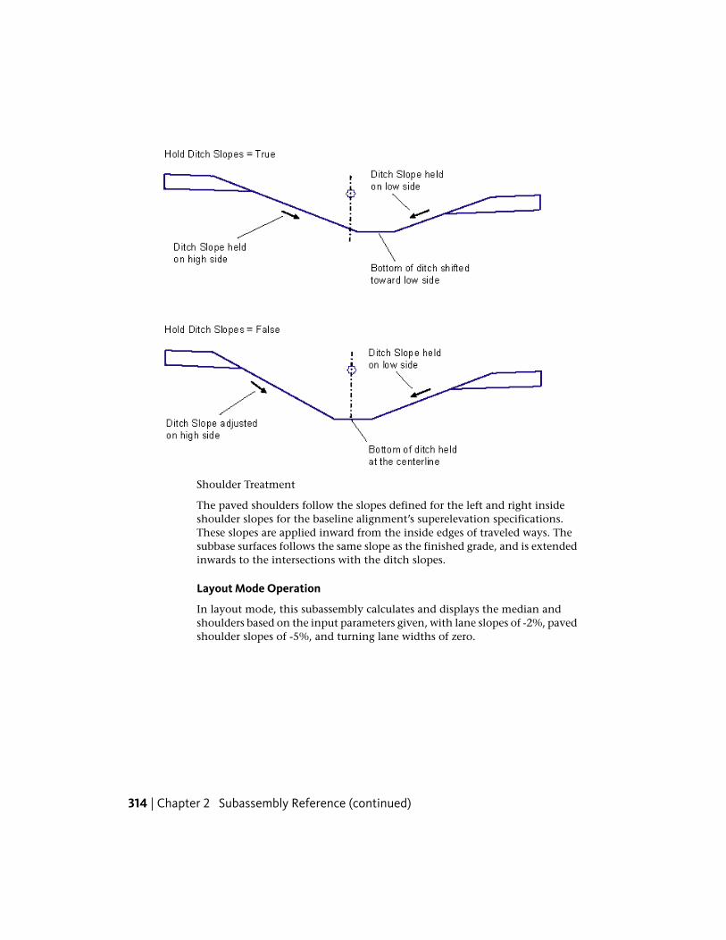
Shoulder Treatment
The paved shoulders follow the slopes defined for the left and right insideshoulder slopes for the baseline alignment’s superelevation specifications.These slopes are applied inward from the inside edges of traveled ways. Thesubbase surfaces follows the same slope as the finished grade, and is extendedinwards to the intersections with the ditch slopes.
Layout Mode Operation
In layout mode, this subassembly calculates and displays the median andshoulders based on the input parameters given, with lane slopes of -2%, pavedshoulder slopes of -5%, and turning lane widths of zero.
314 | Chapter 2 Subassembly Reference (continued)

Point, Link, and Shape CodesThe following table lists the point, link, and shape codes for this subassemblythat have codes assigned to them. Point, link, or shape codes for thissubassembly that do not have codes assigned are not included in this table.
DescriptionCodePoint, Link,or Shape
As shown belowPoints
As shown belowLinks
Pave1S1
Pave2S2
BaseS3
SubbaseS4
Coding Diagram
MedianDepressedShoulderExt | 315

MedianDepressedShoulderVertThis subassembly creates a cross-sectional representation of a depressed medianwith inside shoulders, using vertical termination of shoulder subbase.
It supports superelevation pivoting about the attachment point at thecenterline, or about the attachment point elevation at the insideedges-of-traveled-way. The pavement structure on the paved portions of theshoulder follows the standards described in "Pavement Structure of PavedSections" in the AutoCAD Civil 3DHelp.
316 | Chapter 2 Subassembly Reference (continued)

Table of SlopesTable of Widths
Ditch of ForeslopeS1DitchW1
Unpaved Shoulder SlopeS2Left MedianW2
Left Inside SuperelevationS3Right MedianW3
Right Inside Superelevation Shoulder SlopeS4Paved ShoulderW4
Left Outside Lane SlopeS5Unpaved ShoulderW5
MedianDepressedShoulderVert | 317
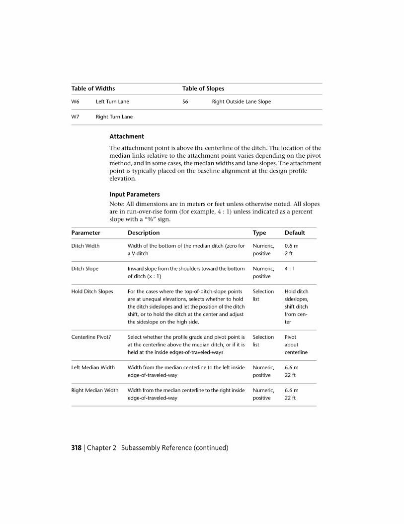
Table of SlopesTable of Widths
Right Outside Lane SlopeS6Left Turn LaneW6
Right Turn LaneW7
Attachment
The attachment point is above the centerline of the ditch. The location of themedian links relative to the attachment point varies depending on the pivotmethod, and in some cases, the median widths and lane slopes. The attachmentpoint is typically placed on the baseline alignment at the design profileelevation.
Input ParametersNote: All dimensions are in meters or feet unless otherwise noted. All slopesare in run-over-rise form (for example, 4 : 1) unless indicated as a percentslope with a “%” sign.
DefaultTypeDescriptionParameter
0.6 mNumeric,positive
Width of the bottom of the median ditch (zero fora V-ditch
Ditch Width2 ft
4 : 1Numeric,positive
Inward slope from the shoulders toward the bottomof ditch (x : 1)
Ditch Slope
Hold ditchsideslopes,
Selectionlist
For the cases where the top-of-ditch-slope pointsare at unequal elevations, selects whether to hold
Hold Ditch Slopes
shift ditchthe ditch sideslopes and let the position of the ditchfrom cen-ter
shift, or to hold the ditch at the center and adjustthe sideslope on the high side.
Pivotaboutcenterline
Selectionlist
Select whether the profile grade and pivot point isat the centerline above the median ditch, or if it isheld at the inside edges-of-traveled-ways
Centerline Pivot?
6.6 mNumeric,positive
Width from the median centerline to the left insideedge-of-traveled-way
Left Median Width22 ft
6.6 mNumeric,positive
Width from the median centerline to the right insideedge-of-traveled-way
Right Median Width22 ft
318 | Chapter 2 Subassembly Reference (continued)

DefaultTypeDescriptionParameter
0.6 mNumeric,positive
Width of the paved portion of the inside shoulderPaved ShoulderWidth 2.0 ft
1.2 mNumeric,positive
Width of the unpaved portion of the inside shoulderUnpaved ShoulderWidth 4.0 ft
-6 (%)Numeric% slope of the unpaved portion of the insideshoulder
Unpaved Shoulder%Slope
0.025 mNumeric,positive
Depth between the finish grade and Pave1 surfacePave1 Depth0.083 ft
0.025 mNumeric,positive
Depth between the Pave1 and Pave2 surfacesPave2 Depth0.083 ft
0.100 mNumeric,positive
Depth between the Pave2 and Base surfacesBase Depth0.333 ft
0.3 mNumeric,positive
Depth between the paved shoulders’ finish gradeand subbase surfaces
Subbase Depth1 ft
0Numeric,positive
Width of the optional turning lane on the left sideLeft Turn Lane Width
0Numeric,positive
Width of the optional turning lane on the right sideRight Turn LaneWidth
Target ParametersThis section lists the parameters in this subassembly that can be mapped toone or more target objects, such as a surface, alignment, or profile object ina drawing. For more information, see Setting Targets in the AutoCAD Civil3D User’s Guide Help.
StatusDescriptionParameter
OptionalMay be used to override the Ditch Slope and tie themedian bottom-of-ditch to a profile. The following
Ditch Slope
object types can be used as targets for specifying this:profiles, 3D polylines, feature lines, or survey figures.
MedianDepressedShoulderVert | 319

StatusDescriptionParameter
OptionalMay be used to override the fixed Left Median Widthand tie the left inside edge-of-traveled-way to an off-
Left Median Width
set alignment. The following object types can be usedas targets for specifying this offset: alignments, poly-lines, feature lines, or survey figures.
OptionalMay be used to override the fixed Right Median Widthand tie the right inside edge-of-traveled-way to an
Right Median Width
offset alignment. The following object types can beused as targets for specifying this offset: alignments,polylines, feature lines, or survey figures.
Output Parameters
None.
Behavior
This subassembly cannot be inserted separately for the left and right sides. Itbuilds the median to both sides of the attachment point.
Superelevation Pivot Point
The median can be configured to have the superelevation pivot point at thecenterline, or at the inside edges of traveled ways. If Centerline Pivot is used,the left and right outside lane superelevation slopes are obtained from thebaseline’s superelevation specifications, and the elevations of the insideedges-of-traveled-ways are calculated by applying these slopes to the left andright median widths from the attachment point. If Centerline Pivot is notused, the edges-of-traveled-ways are held to the elevation of the attachmentpoint.
Ditch Elevations and Slopes
Superelevation or turning lanes may cause the top of the ditch slopes to be atdifferent elevations on the left and right sides, resulting in an asymetricalditch. There are two options for handling this situation. If Hold Ditch Slopesis set to True, then the given ditch slopes are held constant on both sides,which shifts the bottom of ditch away from the centerline towards the lowerside. If set to False, the ditch bottom is centered about the median centerline,the given slope is held on the lower side, and the slope is adjusted to matchon the higher side.
320 | Chapter 2 Subassembly Reference (continued)

Shoulder Treatment
The paved portions of the shoulders follow the slopes defined for the left andright inside shoulder slopes for the baseline alignment’s superelevationspecifications. These slopes are applied inward from the inside edges of traveledways. The unpaved portions of the shoulders are fixed at the given UnpavedShoulder %Slope value.
Layout Mode Operation
In layout mode, this subassembly calculates and displays the median andshoulders based on the input parameters given, and assuming that the laneslopes are -2% and the paved shoulder slopes are -5%.
MedianDepressedShoulderVert | 321

Point, Link, and Shape CodesThe following table lists the point, link, and shape codes for this subassemblythat have codes assigned to them. Point, link, or shape codes for thissubassembly that do not have codes assigned are not included in this table.
DescriptionCodePoint, Link, orShape
Edges of paved shoulder on finish gradeEPSP2, P7
Edges of paved shoulder on Pave1EPS_Pave1P10, P17
Edges of paved shoulder on Pave2EPS_Pave2P12, P19
Edges of paved shoulder on BaseEPS_BaseP14, P21
Edges of paved shoulder on SubbaseEPS_SubP16, P23
Edges of gravel shoulderES_UnpavedP3, P6
Left edge of median ditchLMedDitchP4
Right edge of median ditchRMedDitchP5
Finish grade on paved shouldersTopL1, L7Pave
Finish grade on unpaved shoulder and median linksTopL2 – L6Datum
Pave1L8, L12
Pave2L9, L13
BaseL10, L14
SubBaseL11, L15
Subbase and vertical links on paved shouldersDatumL11, L15, L16,L17
Pave1S1, S5
Pave2S2, S6
322 | Chapter 2 Subassembly Reference (continued)

DescriptionCodePoint, Link, orShape
BaseS3, S7
SubbaseS4, S8
Coding Diagram
MedianFlushWithBarrierThis subassembly inserts surfaces to define a flush median with an optionalNew Jersey Barrier.
The pavement structure follows the standards described in “Pavement Structureof Paved Sections" in the AutoCAD Civil 3D Help.
MedianFlushWithBarrier | 323

Attachment
The attachment point is at the center of median on the finish grade surface.This component inserts to the left and right side simultaneously.
Input ParametersNote: All dimensions are in meters or feet unless otherwise noted. All slopesare in run-over-rise form (for example, 4 : 1) unless indicated as a percentslope with a “%” sign.
DefaultTypeDescriptionParameter
-2 %Selection listSlope of the left median surfaceLeft Slope
-2 %Selection listSlope of the right median surfaceRight Slope
Include Barri-er
Selection listTrue shows the New Jersey barrier.False omits the barrier.
Include Barrier
1.2 mNumeric, posit-ive
Width from the median centerline to the left edgeof median
Left Width4.0 ft
1.2 mNumeric, posit-ive
Width from the median centerline to the rightedge of median
Right Width4.0 ft
Inside LaneSlope
Selection listSpecifies to use superelevation slope for the leftlane
Left Lane - UseSuperelevation
324 | Chapter 2 Subassembly Reference (continued)

DefaultTypeDescriptionParameter
- 2 %NumericSpecifies the default slope of the left lane, if super-elevation slope is not specified
Default LeftSlope
Inside LaneSlope
Selection listSpecifies to use superelevation slope for the rightlane.
Right Lane -Use Supereleva-tion
- 2 %NumericSpecifies the default slope of the right lane, if su-perelevation slope is not specified
Default RightSlope
0.025mNumeric, posit-ive
Thickness of the Pave1 layer; zero to omitPave1 Depth0.083 ft
0.025 mNumeric, posit-ive
Thickness of the Pave2 layer; zero to omit.Pave2 Depth0.083 ft
0.100 mNumeric, posit-ive
Thickness of the base layerBase Depth0.333 ft
0.300 mNumeric, posit-ive
Thickness of the subbase layerSubbase Depth1.0 ft
810 mmNumeric, posit-ive
Height of the barrier at the center of medianDimension A(mm or inches) 32 in
232Numeric, posit-ive
As shown in diagramDimension B(mm or inches) 9 in
59 mmNumeric, posit-ive
As shown in diagramDimension C(mm or inches) 2 in
125 mmNumeric, posit-ive
As shown in diagramDimension D(mm or inches) 5 in
557 mmNumeric, posit-ive
As shown in diagramDimension E(mm or inches) 22 in
178 mmNumeric, posit-ive
As shown in diagramDimension F(mm or inches) 7 in
MedianFlushWithBarrier | 325

Target ParametersThis section lists the parameters in this subassembly that can be mapped toone or more target objects, such as a surface, alignment, or profile object ina drawing. For more information, see Setting Targets in the AutoCAD Civil3D User’s Guide Help.
StatusDescriptionParameter
OptionalMay be used to override the fixed Left Width andtie the left edge-of-median to an offset alignment.
Left Width
The following object types can be used as targetsfor specifying this offset: alignments, polylines,feature lines, or survey figures.
OptionalMay be used to override the fixed Right Widthand tie the right edge-of-median to an offset
Right Width
alignment. The following object types can beused as targets for specifying this offset: align-ments, polylines, feature lines, or survey figures.
Output Parameters
TypeDescriptionParameter
Numeric% slope of the left side of the medianLeft %Slope
Numeric% slope of the right side of the medianRight %Slope
Behavior
The pavement structure links are inserted outward left and right of theattachment point for the given widths and slopes. If the Include Barrier valueis True, a New Jersey barrier is inserted symmetrically about the mediancenterline. If alignments are given as target parameters for the Left and RightWidths, the widths are adjusted to tie to the alignment offsets at each stationalong the corridor.
If the median is in superelevation with a single constant slope across the entiremedian, the top of the barrier is slanted to match the median slope. Otherwisethe top of the barrier remains horizontal. In all cases, the barrier height(Dimension A) is held constant at the centerline of the barrier.
326 | Chapter 2 Subassembly Reference (continued)

Layout Mode Operation
In layout mode, this subasssembly displays all pavement links using the widthand depth input parameters at a -2% slope. If Include Barrier is True, the barrieris displayed with the given dimensions.
Point, Link, and Shape CodesThe following table lists the point, link, and shape codes for this subassemblythat have codes assigned to them. Point, link, or shape codes for thissubassembly that do not have codes assigned are not included in this table.
DescriptionCodePoint, Link, or Shape
All points on the concrete barrierBarrierAll barrier points
Inside edge of lane on finish gradeETWP1, P3
Crown of median on finish gradeCrownP2
Edge-of-traveled-way on Pave1ETW_Pave1P4, P6
Crown on Pave1Crown_Pave1P5
Edge-of-traveled-way on Pave2ETW_Pave2P7, P9
Crown on Pave2Crown_Pave2P8
Edge-of-traveled-way on BaseETW_BaseP10, P12
Crown on BaseCrown_BaseP11
Edge-of-traveled-way on SubbaseETW_SubP13, P15
Crown on SubbaseCrown_SubP14
Top, PaveL1, L2
MedianFlushWithBarrier | 327

DescriptionCodePoint, Link, or Shape
Pave1L3, L4
Pave2L5, L6
BaseL7, L8
SubbaseL9, L10Datum
BarrierAll barrier links
Area between finish grade and Pave1Pave1S1
Area between Pave1 and Pave2Pave2S2
Area between Pave2 and BaseBaseS3
Area between Base and SubbaseSubbaseS4
Shape inclosed by the barrier.BarrierS5
Coding Diagram
328 | Chapter 2 Subassembly Reference (continued)

MedianRaisedConstantSlopeThis subassembly inserts links for a constant-slope raised median between twopoints.
Use the MarkPoint subassembly first if the connecting point has not alreadybeen marked.
Attachment
The attachment point may be at either edge of the median finished grade.The marked point must be at the opposite edge.
Input ParametersNote: Subbase dimensions are in meters or feet. Curb-and-gutter dimensionsmust be given in millimeters or inches.
DefaultTypeDescriptionParameter
NoneStringName of the marked point on the median edge oppositethe attachment point
Marked Point
0.100 mNumeric,positive
Depth of the median cap. May be zero for an unpavedmedian
Depth0.333 ft
Target Parameters
This section lists the parameters in this subassembly that can be mapped toone or more target objects, such as a surface, alignment, or profile object ina drawing. For more information, see Setting Targets in the AutoCAD Civil3D User’s Guide Help.
Target Parameters: None.
Output Parameters
None.
MedianRaisedConstantSlope | 329

Behavior
The top of median link is inserted between the attachment point and markedpoint. If a non-zero Depth is given, the bottom of median link is insertedparallel to the top, and vertical links are added to close the shape.
Point, Link, and Shape CodesThe following table lists the point, link, and shape codes for this subassemblythat have codes assigned to them. Point, link, or shape codes for thissubassembly that do not have codes assigned are not included in this table.
DescriptionCodePoint, Link,or Shape
Edges of median on finish gradeNoneP1, P2
P3, P4
Top of medianTopL1
Bottom of medianDatumL2
NoneL3, L4
MedianS1
Layout Mode Operation
In layout mode, this subassembly shows the generic layout mode display.
Coding Diagram
MedianRaisedWithCrownThis subassembly inserts links for a constant-slope raised median between twopoints.
330 | Chapter 2 Subassembly Reference (continued)
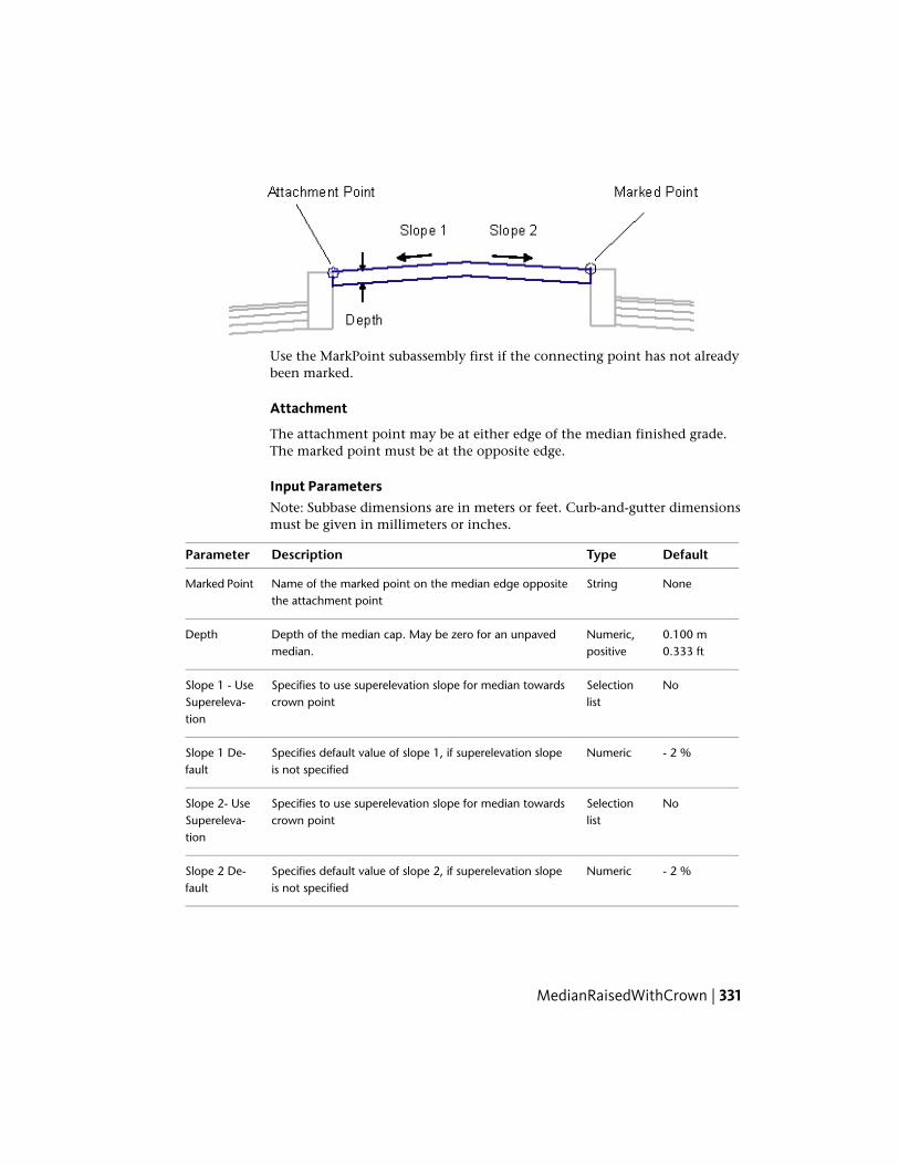
Use the MarkPoint subassembly first if the connecting point has not alreadybeen marked.
Attachment
The attachment point may be at either edge of the median finished grade.The marked point must be at the opposite edge.
Input ParametersNote: Subbase dimensions are in meters or feet. Curb-and-gutter dimensionsmust be given in millimeters or inches.
DefaultTypeDescriptionParameter
NoneStringName of the marked point on the median edge oppositethe attachment point
Marked Point
0.100 mNumeric,positive
Depth of the median cap. May be zero for an unpavedmedian.
Depth0.333 ft
NoSelectionlist
Specifies to use superelevation slope for median towardscrown point
Slope 1 - UseSupereleva-tion
- 2 %NumericSpecifies default value of slope 1, if superelevation slopeis not specified
Slope 1 De-fault
NoSelectionlist
Specifies to use superelevation slope for median towardscrown point
Slope 2- UseSupereleva-tion
- 2 %NumericSpecifies default value of slope 2, if superelevation slopeis not specified
Slope 2 De-fault
MedianRaisedWithCrown | 331

Target Parameters
This section lists the parameters in this subassembly that can be mapped toone or more target objects, such as a surface, alignment, or profile object ina drawing. For more information, see Setting Targets in the AutoCAD Civil3D User’s Guide Help.
Target Parameters: None.
Output Parameters
None.
Behavior
The median crown point is calculated by intersecting lines extended betweenthe attachment point and the marked point at the given slopes. If nointersection is found, the median is not inserted. If a non-zero Depth is given,the bottom of the median links are inserted parallel to the top, and verticallinks are added to close the shape.
Point, Link, and Shape CodesThe following table lists the point, link, and shape codes for this subassemblythat have codes assigned to them. Point, link, or shape codes for thissubassembly that do not have codes assigned are not included in this table.
DescriptionCodePoint, Link,or Shape
NoneP1, P3
Crown of median on finish gradeMedianP2
NoneP4 - P6
Top of medianTopL1, L2
Bottom of median (if given)DatumL3, L4
MedianS1
Layout Mode Operation
In layout mode, this subassembly shows the generic layout mode display.
332 | Chapter 2 Subassembly Reference (continued)

Coding Diagram
OverlayBrokenBackBetweenEdgesThis subassembly is used to overlay a four-lane crowned corridor betweengutter flange points on each side, holding to required slope and breakoverranges. This subassembly differs from OverlayBrokenBackOverGutter becauseit overlays between known flange points, rather than overlaying existing gutterto a known profile on the face of curb.
To use this subassembly, you should have separate alignments defining theleft and right edges. Elevations at these points could come from surfaces orprofiles. Furthermore, if the component defining the edges (for example, curband gutter) is also a rehab component, then they could be passed in as markedpoints, thus transferring offset and elevation information.
Attachment
The attachment point is (near) the crown point of the subassembly. This istypically at the assembly baseline point. While in layout mode, this pointcoincides with crown point, in the corridor state the finshed grade profilepoint (or baseline marker point) may not be same as crown point, since itsoffset and elevation are computed by edge of pavement data.
OverlayBrokenBackBetweenEdges | 333
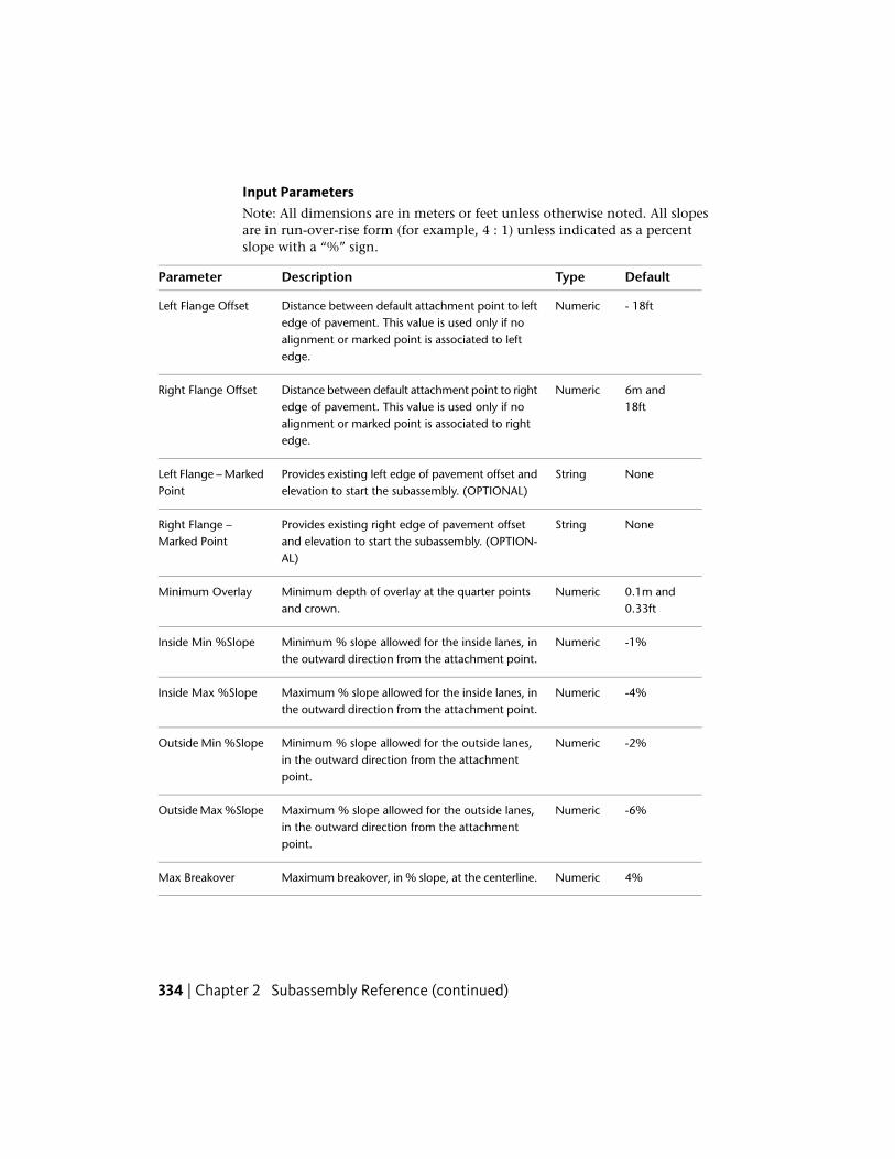
Input ParametersNote: All dimensions are in meters or feet unless otherwise noted. All slopesare in run-over-rise form (for example, 4 : 1) unless indicated as a percentslope with a “%” sign.
DefaultTypeDescriptionParameter
- 18ftNumericDistance between default attachment point to leftedge of pavement. This value is used only if no
Left Flange Offset
alignment or marked point is associated to leftedge.
6m and18ft
NumericDistance between default attachment point to rightedge of pavement. This value is used only if no
Right Flange Offset
alignment or marked point is associated to rightedge.
NoneStringProvides existing left edge of pavement offset andelevation to start the subassembly. (OPTIONAL)
Left Flange – MarkedPoint
NoneStringProvides existing right edge of pavement offsetand elevation to start the subassembly. (OPTION-AL)
Right Flange –Marked Point
0.1m and0.33ft
NumericMinimum depth of overlay at the quarter pointsand crown.
Minimum Overlay
-1%NumericMinimum % slope allowed for the inside lanes, inthe outward direction from the attachment point.
Inside Min %Slope
-4%NumericMaximum % slope allowed for the inside lanes, inthe outward direction from the attachment point.
Inside Max %Slope
-2%NumericMinimum % slope allowed for the outside lanes,in the outward direction from the attachmentpoint.
Outside Min %Slope
-6%NumericMaximum % slope allowed for the outside lanes,in the outward direction from the attachmentpoint.
Outside Max %Slope
4%NumericMaximum breakover, in % slope, at the centerline.Max Breakover
334 | Chapter 2 Subassembly Reference (continued)

DefaultTypeDescriptionParameter
0.05m and0.16ft
NumericMinimum crown deflection at the quarter points.Min Crown Deflec-tions
Note that if target parameters are provided, the preceding parameters (namelydefault offsets and marked points) will be ignored as applicable.
Target ParametersThis section lists the parameters in this subassembly that can be mapped toone or more target objects, such as a surface, alignment, or profile object ina drawing. For more information, see Setting Targets in the AutoCAD Civil3D User’s Guide Help.
StatusDescriptionParameter
OptionalProvides left edge of pavement offset value with re-spect to the attachment point. The following object
Left Flange Point
types can be used as targets for specifying this:alignments, polylines, feature lines, or survey figures.
OptionalProvides right edge of pavement offset value withrespect to the attachment point. The following object
Right Flange Point
types can be used as targets for specifying this:alignments, polylines, feature lines, or survey figures.
OptionalProvides left edge of pavement elevation value withrespect to the attachment point. The following object
Left Flange Profile
types can be used as targets for specifying this: pro-files, 3D polylines, feature lines, or survey figures.
OptionalProvides right edge of pavement elevation value withrespect to the attachment point. The following object
Right Flange Profile
types can be used as targets for specifying this: pro-files, 3D polylines, feature lines, or survey figures.
OverlayBrokenBackBetweenEdges | 335

StatusDescriptionParameter
RequiredIf profiles are not supplied for left/right edge ofpavement elevations, then this surface elevation at
EGTopSurf
that offset will be picked up as elevation value (forleft/right) respectively. The following object typescan be used as targets for specifying this surface:surfaces.
Output Parameters
TypeDescriptionParameter
Numeric% slope of the left outside laneLeft Outside Lane%Slope
Numeric% slope of the left inside laneLeft Inside Lane %Slope
Numeric% slope of the right outside laneRight Outside Lane%Slope
Numeric% slope of the right inside laneRight Inside Lane%Slope
Behavior
This subassembly uses an iterative process to develop acceptable slopes of theinside and outside links. The initial slopes are set as described below. Eachtime the slope of one link is adjusted, resulting changes in the adjacent linksmay put them out of design tolerances. If a solution is not obtained within10 iterations, a message is displayed and the process is aborted.
Left Edge of Pavement
From the attachment point, the left edge of the pavement point is locatedbased on: (a) the location of the alignment through the "Left Flange Point"target parameter, (b) if this is not provided, it is based on the assigned markedpoint (to Left Flange Point), or (c) if both of these are not provided, then it isbased on the default (Left Flange Offset) offset value.
Similarly, the elevation for this point is computed based on: (a) the Left Flangeprofile target parameter, (b) if this is not provided, then the surface elevationis determined from the "EGTopSurf" Logical assignment , or (c) if both of theseare not provided, then the assigned marked point determines the elevation.
336 | Chapter 2 Subassembly Reference (continued)
An error message results if none of these two conditions are met and thecorridor fails to build.
Right Edge of Pavement
From the attachment point, the right edge of pavement point is located basedon: (a) location of alignment through "Right Flange Point" target parameters,(b) if previous is not provided, based on the assigned marked point (to RightFlange Point), or (c) if both are not provided based on the default (Right FlangeOffset) offset value.
Similarly, elevation for this point is computed based on: (a) Right Flangeprofile target parameters assignment, or (b) if previous is not provided thenfinding out the surface elevation from "EGTopSurf" Logical assignment, or (c)if the previous two are not provided, the assigned marked point determinesthe elevation. An error message results if none of these two conditions aremet and the corridor fails to build.
Crown Point
The Crown Point (offset) is located at halfway between the left edge and rightedge of pavements.
Elevation of the crown point is the sum of "average elevation of left and rightedges" and the "crown height" parameter value.
Bottom of Overlay
Bottom of overlay surface is computed by offsetting the proposed finish grade(Left Edge point to New Crown Point to Right Edge Point) by Overlay depthvalue.
Quarter Points and Crown Point Offsets
The distance between left and right flange points is divided by four to get thetwo quarter points and the crown point. These points elevations are computedby adding the minimum overlay depth to the existing ground at these offsets.
Inside and Outside Pavement Slopes
The resulting overlay links from the previous steps are checked for being withinthe slope tolerances for the outside and inside lanes. If the slopes are withinthe tolerence, then the case is a simple overlay as shown in the followingdiagram.
OverlayBrokenBackBetweenEdges | 337

If overlay links are too steep, or if the Maximum Breakover is exceeded at thecenterline, or the Min Crown Deflection is not obtained, some or all links areflattened to their maximum slopes. Milling surfaces are inserted to hold theminimum overlay depths at the quarter points and centerline.
If overlay links are too shallow, the depth of overlay is increased to achievethe minimum slopes. If this results in too much breakover, further adjustmentsand milling may occur. The following diagram explains overlay with millingcase:
Special Cases
A positive slope may be allowed on one inside link if the other inside link hasa negative slope, as shown below.
338 | Chapter 2 Subassembly Reference (continued)
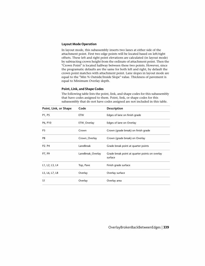
Layout Mode Operation
In layout mode, this subassembly inserts two lanes at either side of theattachment point. First two edge points will be located based on left/rightoffsets. These left and right point elevations are calculated (in layout mode)by subtracting crown height from the ordinate of attachment point. Then the"Crown Point" is located halfway between these two points. However, sincethe programatic defaults are the same for both left and right, by default thecrown point matches with attachment point. Lane slopes in layout mode areequal to the "Min % Outside/Inside Slope" value. Thickness of pavement isequal to Minimum Overlay depth.
Point, Link, and Shape CodesThe following table lists the point, link, and shape codes for this subassemblythat have codes assigned to them. Point, link, or shape codes for thissubassembly that do not have codes assigned are not included in this table.
DescriptionCodePoint, Link, or Shape
Edges of lane on finish gradeETWP1, P5
Edges of lane on OverlayETW_OverlayP6, P10
Crown (grade break) on finish gradeCrownP3
Crown (grade break) on OverlayCrown_OverlayP8
Grade break point at quarter pointsLaneBreakP2. P4
Grade break point at quarter points on overlaysurface
LaneBreak_OverlayP7, P9
Finish grade surfaceTop, PaveL1, L2, L3, L4
Overlay surfaceOverlayL5, L6, L7, L8
Overlay areaOverlayS1
OverlayBrokenBackBetweenEdges | 339

Coding Diagram
OverlayBrokenBackOverGuttersThis subassembly is used to overlay a four-lane crowned corridor over gutters(between flow lines) on each side, holding to required slope and breakoverranges. This subassembly differs from OverlayBrokenBackBetweenEdges becauseit overlays existing gutters to a known profile on the curb face, rather thanoverlaying between known flange points.
To use this subassembly, you should have separate alignments defining theleft and right curb face points. Elevations at these points could come fromsurfaces or profiles. Furthermore, if the component defining the edges (forexample, curb and gutter) is also a rehab component, then they could bepassed in as marked points, thus transferring offset and elevation information.
Attachment
The attachment point is (near) the crown point of the subassembly. Since thesubassembly places lanes on either side of the crown, this attachment pointis typically at the assembly baseline point. While in layout mode this pointcoincides with crown point, in the corridor state the finished grade profilepoint (or baseline marker point) may not be same as crown point, since crownpoint offset and elevation are computed by input data such as left and right(Curb face) offset values.
340 | Chapter 2 Subassembly Reference (continued)

Input ParametersNote: All dimensions are in meters or feet unless otherwise noted. All slopesare in run-over-rise form (for example, 4 : 1) unless indicated as a percentslope with a “%” sign.
DefaultTypeDescriptionParameter
6m and18ft
NumericDistance between attachment point and the leftgutter’s curb face. This value is used only if no
Left Gutter Offset
alignment or marked point is associated to leftedge.
6m and18ft
NumericDistance between attachment point and the rightgutter’s curb face. This value is used only if no
Right Gutter Offset
alignment or marked point is associated to rightedge.
NoneStringProvides existing left edge of pavement offset andelevation to start the subassembly. (OPTIONAL)
Left Gutter – MarkedPoint
NoneStringProvides existing right edge of pavement offsetand elevation to start the subassembly. (OPTION-AL)
Right Gutter –Marked Point
0.1m and0.33ft
NumericMinimum depth of overlay at the quarter pointsand crown.
Minimum Overlay
-1%NumericMinimum % slope allowed for the inside lanes, inthe outward direction from the attachment point.
Inside Min %Slope
-4%NumericMaximum % slope allowed for the inside lanes, inthe outward direction from the attachment point.
Inside Max %Slope
-2%NumericMinimum % slope allowed for the outside lanes,in the outward direction from the attachmentpoint.
Outside Min %Slope
-6%NumericMaximum % slope allowed for the outside lanes,in the outward direction from the attachmentpoint.
Outside Max %Slope
4%NumericMaximum breakover, in % slope, at the centerline.Max Breakover
OverlayBrokenBackOverGutters | 341

DefaultTypeDescriptionParameter
0.05mand 0.16ft
NumericMinimum crown deflection at the quarter points.Min Crown Deflec-tions
If target parameters are provided, the parameters above (namely default offsetsand marked points) will be ignored as applicable.
Target ParametersThis section lists the parameters in this subassembly that can be mapped toone or more target objects, such as a surface, alignment, or profile object ina drawing. For more information, see Setting Targets in the AutoCAD Civil3D User’s Guide Help.
StatusDescriptionParameter
OptionalProvides left edge of pavement offset value with respectto the attachment point. The following object types can
Left Gutter Point
be used as targets for specifying this: alignments, poly-lines, feature lines, or survey figures.
OptionalProvides right edge of pavement offset value with re-spect to the attachment point. The following object
Right Gutter Point
types can be used as targets for specifying this: align-ments, polylines, feature lines, or survey figures.
OptionalProvides left edge of pavement elevation value with re-spect to the attachment point. The following object
Left Gutter Profile
types can be used as targets for specifying this elevation:profiles, 3D polylines, feature lines, or survey figures.
OptionalProvides right edge of pavement elevation value withrespect to the attachment point. The following object
Right Gutter Profile
types can be used as targets for specifying this elevation:profiles, 3D polylines, feature lines, or survey figures.
342 | Chapter 2 Subassembly Reference (continued)

StatusDescriptionParameter
RequiredIf profiles are not supplied for left/right edge of pave-ment elevations, then this surface elevation at that offset
EGTopSurf
will be picked up as elevation value (for left/right) re-spectively.
Output Parameters
TypeDescriptionParameter
Numeric% slope of the left outside laneLeft Outside Lane%Slope
Numeric% slope of the left inside laneLeft Inside Lane %Slope
Numeric% slope of the right outside laneRight Outside Lane%Slope
Numeric% slope of the right inside laneRight Inside Lane%Slope
Behavior
This subassembly uses an iterative pocess to develop acceptable slopes of theinside and outside links. The initial slopes are set as described below. Eachtime the slope of one link is adjusted, resulting changes in the adjacent linksmay put them out of design tolerances. If a solution is not obtained within10 iterations, a message is displayed and the process is aborted.
Left Edge of Pavement
From the attachment point, the left edge of the pavement point is locatedbased on: (a) the location of the alignment through "Left Gutter Point" targetparameters, (b) if this is not provided, then it is based on the assigned markedpoint (to Left Gutter Point), or (c) if both of these are not provided, it is basedon the default (Left Gutter Offset) offset value.
Similarly, the elevation for this point is computed based on: (a) Left Gutterprofile target parameter, (b) if this is not provided, then it determines thesurface elevation from "EGTopSurf" Logical assignment, or (c) if these two arenot provided, then the assigned marked point determines the elevation. Anerror messageresults if none of these two conditions are met and the corridorfails to build.
OverlayBrokenBackOverGutters | 343
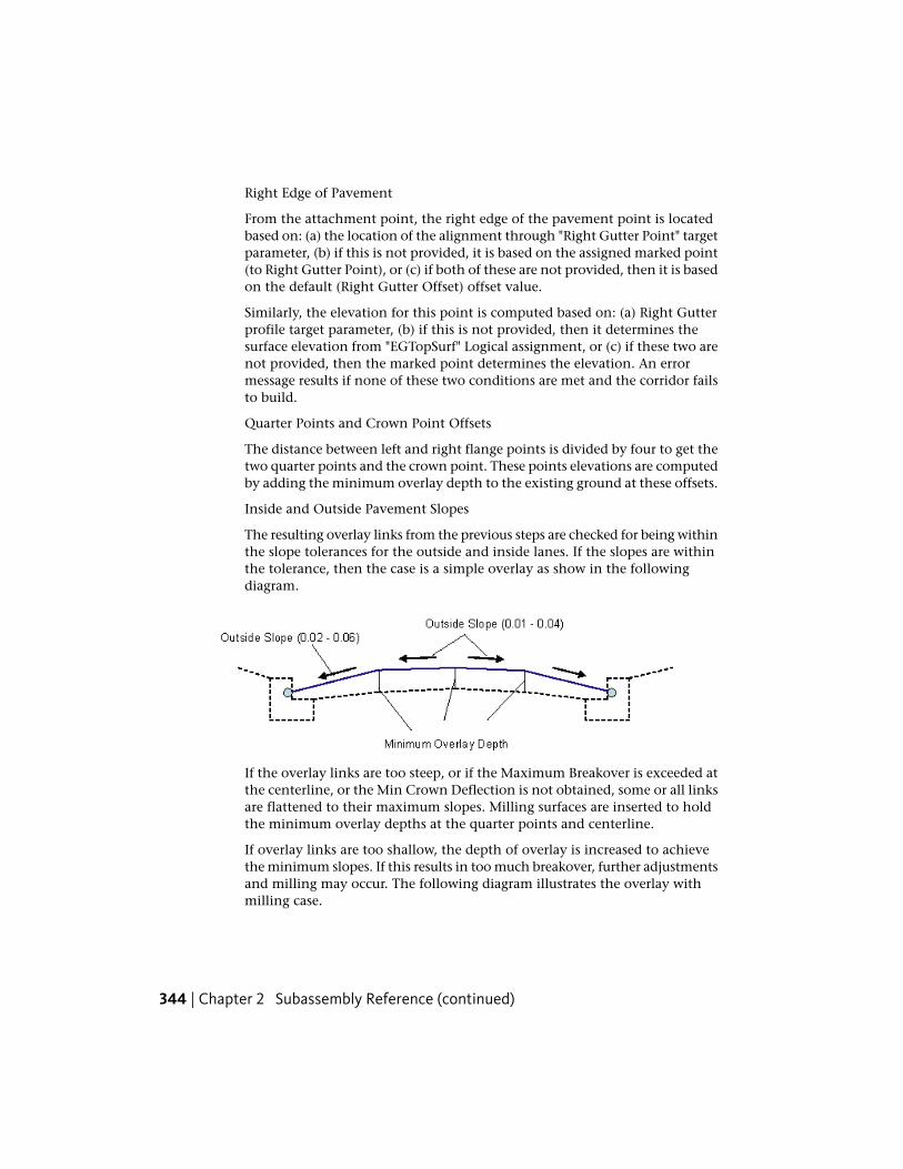
Right Edge of Pavement
From the attachment point, the right edge of the pavement point is locatedbased on: (a) the location of the alignment through "Right Gutter Point" targetparameter, (b) if this is not provided, it is based on the assigned marked point(to Right Gutter Point), or (c) if both of these are not provided, then it is basedon the default (Right Gutter Offset) offset value.
Similarly, the elevation for this point is computed based on: (a) Right Gutterprofile target parameter, (b) if this is not provided, then it determines thesurface elevation from "EGTopSurf" Logical assignment, or (c) if these two arenot provided, then the marked point determines the elevation. An errormessage results if none of these two conditions are met and the corridor failsto build.
Quarter Points and Crown Point Offsets
The distance between left and right flange points is divided by four to get thetwo quarter points and the crown point. These points elevations are computedby adding the minimum overlay depth to the existing ground at these offsets.
Inside and Outside Pavement Slopes
The resulting overlay links from the previous steps are checked for being withinthe slope tolerances for the outside and inside lanes. If the slopes are withinthe tolerance, then the case is a simple overlay as show in the followingdiagram.
If the overlay links are too steep, or if the Maximum Breakover is exceeded atthe centerline, or the Min Crown Deflection is not obtained, some or all linksare flattened to their maximum slopes. Milling surfaces are inserted to holdthe minimum overlay depths at the quarter points and centerline.
If overlay links are too shallow, the depth of overlay is increased to achievethe minimum slopes. If this results in too much breakover, further adjustmentsand milling may occur. The following diagram illustrates the overlay withmilling case.
344 | Chapter 2 Subassembly Reference (continued)

Special Cases
A positive slope may be allowed on one inside link if the other inside link hasa negative slope, as shown below.
Layout Mode Operation
In layout mode, this subassembly inserts two lanes at either side of theattachment point. The firts two edge points will be located based on left/rightoffsets. These left and right point elevations are calculated, in layout mode,by subtracting crown height from the ordinate of attachment point. Then the"Crown Point" is located halfway between these two points. However, sincethe programatic defaults are the same for both left and right, by default, thecrown point matches the attachment point. Lane slopes in layout mode areequal to the "Min % Outside/Inside Slope" value. Thickness of pavement isequal to Minimum Overlay depth.
OverlayBrokenBackOverGutters | 345

Point, Link, and Shape CodesThe following table lists the point, link, and shape codes for this subassemblythat have codes assigned to them. Point, link, or shape codes for thissubassembly that do not have codes assigned are not included in this table.
DescriptionCodePoint, Link, or Shape
Edges of lane on finish gradeETWP1, P5
Edges of lane on OverlayETW_OverlayP6, P10
Crown (grade break) on finish gradeCrownP3
Crown (grade break) on OverlayCrown_OverlayP8
Grade break point at quarter pointsLaneBreakP2. P4
Grade break point at quarter points on overlaysurface
LaneBreak_OverlayP7, P9
Finish grade surfaceTop, PaveL1, L2, L3, L4
Overlay surfaceOverlayL5, L6, L7, L8
Overlay areaOverlayS1
Coding Diagram
OverlayCrownBetweenEdgesThis subassembly creates a simple crowned roadway between twoedge-of-pavement points.
346 | Chapter 2 Subassembly Reference (continued)

To use this subassembly, you should have separate alignments defining theleft and right edges. Elevations at these points could come from surfaces orprofiles. Furthermore, if the component defining the edges (for example, curband gutter) is also a rehab component, then they could be passed in as markedpoints, thus transferring offset and elevation information.
Attachment
The attachment point is (near) the crown point of the subassembly. This istypically at the assembly baseline point. While in layout mode, this pointcoincides with crown point, in the corridor state the finshed grade profilepoint (or baseline marker point) may not be the same as crown point sinceits offset and elevation are computed by edge of pavement data.
Input ParametersNote: All dimensions are in meters or feet unless otherwise noted. All slopesare in run-over-rise form (for example, 4 : 1) unless indicated as a percentslope with a “%” sign.
DefaultTypeDescriptionParameter
3.6m and12ft
NumericDistance between default attachment point to leftedge of pavement. This value is used only if no
Left Edge Offset
alignment or marked point is associated to leftedge.
OverlayCrownBetweenEdges | 347

DefaultTypeDescriptionParameter
3.6m and12ft
NumericDistance between default attachment point to rightedge of pavement. This value is used only if no
Right Edge Offset
alignment or marked point is associated to rightedge.
NoneStringProvides existing left edge of pavement offset andelevation to start the subassembly. (OPTIONAL)
Left Edge – MarkedPoint
NoneStringProvides existing right edge of pavement offsetand elevation to start the subassembly. (OPTION-AL)
Right Edge – MarkedPoint
0.1m and0.33ft
NumericHeight from the center point of the string line tothe crown point.
Crown Height
-1%NumericMinimum % slope allowed for the outside lanes,in the outward direction from the attachmentpoint.
Min %Slope
-3%NumericMaximum % slope allowed for the outside lanes,in the outward direction from the attachmentpoint.
Max %Slope
0.1m and0.30ft
NumericDepth of overlay above existing finish grades.Overlay Depth
If target parameters are provided, the preceding parameters (namely defaultoffsets and marked points) will be ignored as applicable.
Target ParametersThis section lists the parameters in this subassembly that can be mapped toone or more target objects, such as a surface, alignment, or profile object ina drawing. For more information, see Setting Targets in the AutoCAD Civil3D User’s Guide Help.
StatusDescriptionParameter
OptionalProvides left edge of pavement offset value withrespect to the attachment point. The following
Left Edge
object types can be used as targets for specifying
348 | Chapter 2 Subassembly Reference (continued)

StatusDescriptionParameter
this offset: alignments, polylines, feature lines, orsurvey figures.
OptionalProvides right edge of pavement offset value withrespect to the attachment point. The following
Right Edge
object types can be used as targets for specifyingthis offset: alignments, polylines, feature lines, orsurvey figures.
OptionalProvides left edge of pavement elevation value withrespect to the attachment point. . The following
Left Edge
object types can be used as targets for specifyingthis elevation: profiles, 3D polylines, feature lines,or survey figures.
OptionalProvides right edge of pavement elevation valuewith respect to the attachment point. The following
Right Edge
object types can be used as targets for specifyingthis elevation: profiles, 3D polylines, feature lines,or survey figures.
RequiredIf profiles are not supplied for left/right edge ofpavement elevations, then this surface elevation at
EGTopSurf
that offset will be picked up as elevation value (forleft/right) respectively. The following object typescan be used as targets for specifying this surface:surfaces.
Output Parameters
TypeDescriptionParameter
Numeric% slope of the left laneLeft Lane %Slope
Numeric% slope of the right laneRight Lane %Slope
Behavior
Left Edge of Pavement
From the attachment point, the left edge of the pavement point is locatedbased on: (a) the location of the alignment through "Left Edge" target
OverlayCrownBetweenEdges | 349
parameter, (b) if this is not provided, it is based on the assigned marked point(to Left Edge), or (c) if both of these are not provided, then it is based on thedefault (Left Edge) offset value.
Similarly, the elevation for this point is computed based on: (a) Left Edgeprofile target parameter, (b) if this is not provided, then it determines thesurface elevation from "EGTopSurf" Logical assignment, or (c) if these two arenot provided, the assigned marked pointdetermines the elevation. An errormessage results if none of these two conditions are met and the corridor failsto build.
Right Edge of Pavement
From the attachment point, the right edge of the pavement point is locatedbased on: (a) the location of the alignment through "Right Edge" targetparameter, (b) if previous is not provided, based on the assigned marked point(to Right Edge), or (c) if both are not provided based on the default (RightEdge) offset value.
Similarly , the elevation for this point is computed based on: (a) Right Edgeprofile target parameter, (b) if this is not provided, then it determines thesurface elevation from "EGTopSurf" Logical assignment, or (c) if these two arenot provided, then the assigned marked point determines the elevation. Anerror message results if none of these two conditions are met and the corridorfails to build.
Crown Point
Crown Point (offset) is located at halfway between the left edge and right edgeof pavements.
Elevation of the crown point is the sum of "average elevation of left and rightedges" and the "crown height" parameter value.
Bottom of Overlay
Bottom of overlay surface is computed by offsetting the proposed finish grade(Left Edge point to New Crown Point to Right Edge Point) by Overlay depthvalue.
Layout Mode Operation
In layout mode, this subassembly inserts one lane each on either side of theattachment point. First two edge points will be located based on left/rightoffsets. These left and right point elevations are calculated (in layout mode)by subtracting crown height from the ordinate of attachment point. Then the"Crown Point" is located halfway between these two points. However, sincethe programatic defaults are the same for both left and right, by default the
350 | Chapter 2 Subassembly Reference (continued)
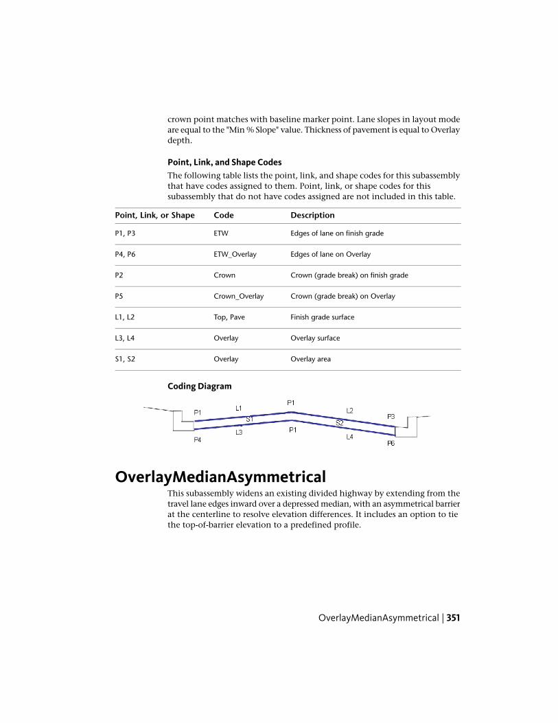
crown point matches with baseline marker point. Lane slopes in layout modeare equal to the "Min % Slope" value. Thickness of pavement is equal to Overlaydepth.
Point, Link, and Shape CodesThe following table lists the point, link, and shape codes for this subassemblythat have codes assigned to them. Point, link, or shape codes for thissubassembly that do not have codes assigned are not included in this table.
DescriptionCodePoint, Link, or Shape
Edges of lane on finish gradeETWP1, P3
Edges of lane on OverlayETW_OverlayP4, P6
Crown (grade break) on finish gradeCrownP2
Crown (grade break) on OverlayCrown_OverlayP5
Finish grade surfaceTop, PaveL1, L2
Overlay surfaceOverlayL3, L4
Overlay areaOverlayS1, S2
Coding Diagram
OverlayMedianAsymmetricalThis subassembly widens an existing divided highway by extending from thetravel lane edges inward over a depressed median, with an asymmetrical barrierat the centerline to resolve elevation differences. It includes an option to tiethe top-of-barrier elevation to a predefined profile.
OverlayMedianAsymmetrical | 351

Attachment
The attachment point is the center of the base of the barrier.
Input ParametersNote: All dimensions are in meters or feet unless otherwise noted. All slopesare in run-over-rise form (for example, 4 : 1) unless indicated as a percentslope with a “%” sign.
DefaultTypeDescriptionParameter
0.100 mNumeric, posit-ive
Thickness of the median overlay layers.Overlay Depth0.3 ft
352 | Chapter 2 Subassembly Reference (continued)

DefaultTypeDescriptionParameter
0.0NumericOffset where the median extension layer beginson the left side.
Left Insert Off-set
0.0NumericOffset of the inside sample point on the left side.The slope of the left side is calculated on the exist-ing surface between the sample points.
Left InsideSample Offset
0.0NumericOffset of the outside sample point on the left side.The slope of the left side is calculated on the exist-ing surface between the sample points.
Left OutsideSample Offset
0.0NumericOffset where the median extension layer beginson the right side.
Right Insert Off-set
0.0NumericOffset of the inside sample point on the right side.The slope of the right side is calculated on theexisting surface between the sample points.
Right InsideSample Offset
0.0NumericOffset of the outside sample point on the rightside. The slope of the right side is calculated onthe existing surface between the sample points.
Right OutsideSample Offset
810 mmNumeric, posit-ive
Height of the barrier from the base on the highside of the median to the top of the barrier.
Dimension A(mm or inches) 32 in
232Numeric, posit-ive
As shown in diagram.Dimension B(mm or inches) 9 in
59 mmNumeric, posit-ive
As shown in diagram.Dimension C(mm or inches) 2 in
125 mmNumeric, posit-ive
As shown in diagram.Dimension D(mm or inches) 5 in
557 mmNumeric, posit-ive
As shown in diagram.Dimension E(mm or inches) 22 in
178 mmNumeric, posit-ive
As shown in diagram.Dimension F(mm or inches) 7 in
OverlayMedianAsymmetrical | 353

Target ParametersThis section lists the parameters in this subassembly that can be mapped toone or more target objects, such as a surface, alignment, or profile object ina drawing. For more information, see Setting Targets in the AutoCAD Civil3D User’s Guide Help.
StatusDescriptionParameter
RequiredName of the Surface defining the existing road-way. The following object types can be used astargets for specifying this surface: surfaces.
Existing Surface
OptionalMay be used to tie the top of barrier to the eleva-tion of a profile. Dimension E may vary to achieve
Top of Barrier
the calculated barrier height. The following objecttypes can be used as targets for specifying thiselevation: profiles, 3D polylines, feature lines, orsurvey figures.
OptionalMay be used to calculate the offset of the left in-sert point from an alignment. The following object
Left Insert Offset
types can be used as targets for specifying thisoffset: alignments, polylines, feature lines, or sur-vey figures.
OptionalMay be used to calculate the offset of the left in-side sample point from an alignment. The follow-
Left Inside Sample Offset
ing object types can be used as targets for specify-ing this offset: alignments, polylines, feature lines,or survey figures.
OptionalMay be used to calculate the offset of the leftoutside sample point from an alignment. The fol-
Left Outside SampleOffset
lowing object types can be used as targets forspecifying this offset: alignments, polylines, featurelines, or survey figures.
OptionalMay be used to calculate the offset of the rightinsert point from an alignment. The following
Right Insert Offset
object types can be used as targets for specifyingthis offset: alignments, polylines, feature lines, orsurvey figures.
354 | Chapter 2 Subassembly Reference (continued)

StatusDescriptionParameter
OptionalMay be used to calculate the offset of the rightinside sample point from an alignment. The fol-
Right Inside Sample Off-set
lowing object types can be used as targets forspecifying this offset: alignments, polylines, featurelines, or survey figures.
OptionalMay be used to calculate the offset of the rightoutside sample point from an alignment. The fol-
Right Outside SampleOffset
lowing object types can be used as targets forspecifying this offset: alignments, polylines, featurelines, or survey figures.
Output Parameters
None.
Behavior
The left and right slopes are calculated between the sample points on eachside. Lines from the cutout points are extended inward at these slopes to thecenterline. The side with the highest elevation at the centerline determinesthe controlling side for the minimum height of the barrier.
The offset of the barrier base on the high side is calculated from the givendimensions. The overlay layer on the high side is extended from the cutoutpoint to this offset.
The overlay layer on the low side is extended from the cutout point to theoffset of the barrier base on the high side.
The barrier is constructed from the base point on the high side, closing to thetop of the overlay layer on the low side, as shown in the diagram.
If a top-of-barrier profile is given as a target parameter, the height of the barrieris controlled by the profile. Dimension E may vary to achieve this height.
Layout Mode Operation
In layout mode, a symmetrical median and barrier are drawn with the fixeddimensions shown below. This is the same figure that is drawn in layout modefor the OverlayMedianSymmetrical subassembly.
OverlayMedianAsymmetrical | 355
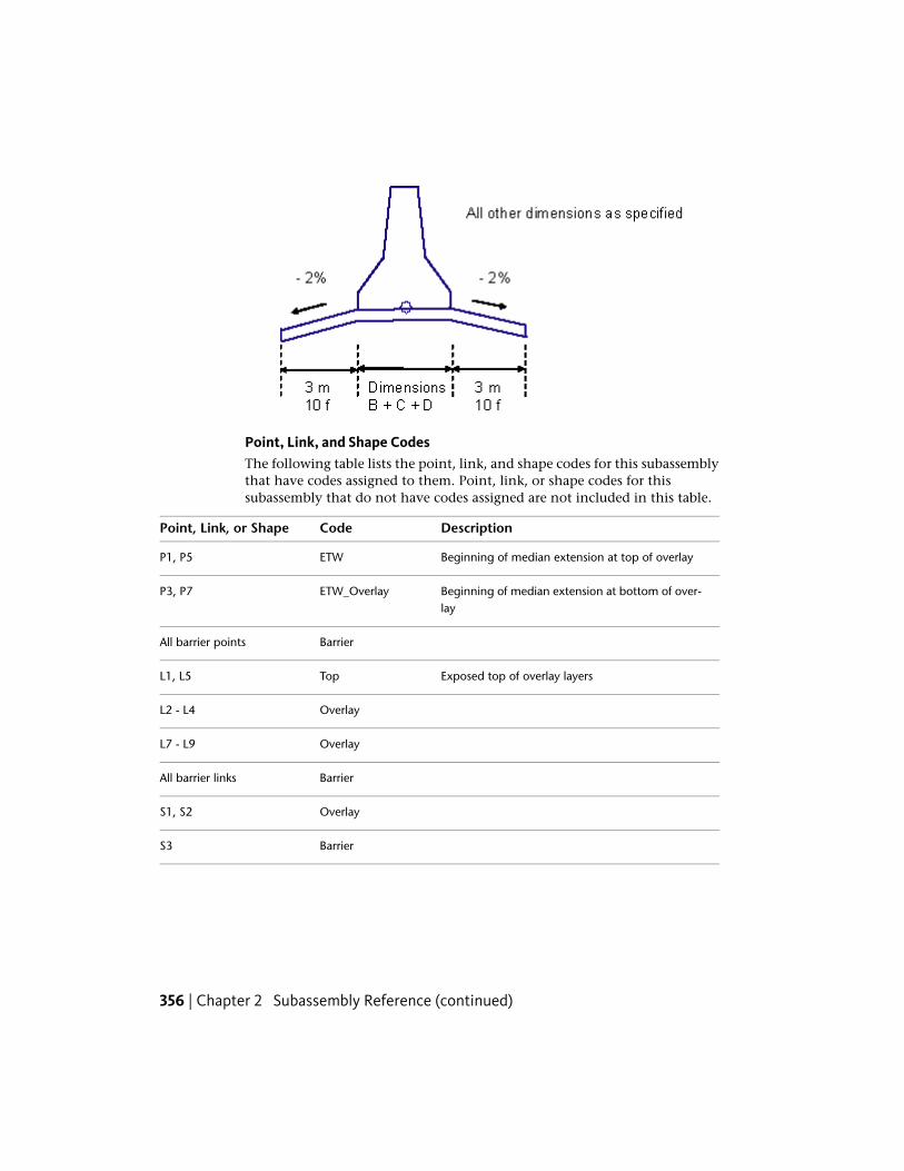
Point, Link, and Shape CodesThe following table lists the point, link, and shape codes for this subassemblythat have codes assigned to them. Point, link, or shape codes for thissubassembly that do not have codes assigned are not included in this table.
DescriptionCodePoint, Link, or Shape
Beginning of median extension at top of overlayETWP1, P5
Beginning of median extension at bottom of over-lay
ETW_OverlayP3, P7
BarrierAll barrier points
Exposed top of overlay layersTopL1, L5
OverlayL2 - L4
OverlayL7 - L9
BarrierAll barrier links
OverlayS1, S2
BarrierS3
356 | Chapter 2 Subassembly Reference (continued)

Coding Diagram
NOTE The mirror image will apply when the high side of the median is on theright instead of the left.
OverlayMedianSymmetricalThis subassembly widens an existing divided highway by extending from thetravel lane edges inward over a depressed median, with a symmetrical barrierat the centerline. The median slopes may vary somewhat from the existingslopes to make both sides meet at the centerline, or to hold the top of thebarrier to a profile.
OverlayMedianSymmetrical | 357

Attachment
The attachment point is at the midpoint of the base of the barrier.
Input ParametersNote: All dimensions are in meters or feet unless otherwise noted. All slopesare in run-over-rise form (for example, 4 : 1) unless indicated as a percentslope with a “%” sign.
DefaultTypeDescriptionParameter
0.100 mNumeric, posit-ive
Thickness of the median overlay layers.Overlay Depth0.3 ft
5%Numeric, posit-ive
Amount that the median % slopes are allowed tovary from the calculated existing Left and Rightslopes.
Slope Tolerance
0.0NumericOffset where the median extension layer beginson the left side.
Left Insert Off-set
358 | Chapter 2 Subassembly Reference (continued)

DefaultTypeDescriptionParameter
0.0NumericOffset of the inside sample point on the left side.The slope of the left side is calculated on the exist-ing surface between the sample points.
Left InsideSample Offset
0.0NumericOffset of the outside sample point on the left side.The slope of the left side is calculated on the exist-ing surface between the sample points.
Left OutsideSample Offset
0.0NumericOffset where the median extension layer beginson the right side.
Right Insert Off-set
0.0NumericOffset of the inside sample point on the right side.The slope of the right side is calculated on theexisting surface between the sample points.
Right InsideSample Offset
0.0NumericOffset of the outside sample point on the rightside. The slope of the right side is calculated onthe existing surface between the sample points.
Right OutsideSample Offset
810 mmNumeric, posit-ive
Height of the barrier from the base on the highside of the median to the top of the barrier.
Dimension A(mm or inches) 32 in
232Numeric, posit-ive
As shown in diagram.Dimension B(mm or inches) 9 in
59 mmNumeric, posit-ive
As shown in diagram.Dimension C(mm or inches) 2 in
125 mmNumeric, posit-ive
As shown in diagram.Dimension D(mm or inches) 5 in
557 mmNumeric, posit-ive
As shown in diagram.Dimension E(mm or inches) 22 in
178 mmNumeric, posit-ive
As shown in diagram.Dimension F(mm or inches) 7 in
Target ParametersThis section lists the parameters in this subassembly that can be mapped toone or more target objects, such as a surface, alignment, or profile object in
OverlayMedianSymmetrical | 359
a drawing. For more information, see Setting Targets in the AutoCAD Civil3D User’s Guide Help.
StatusDescriptionParameter
RequiredName of the Surface defining the existing roadway.The following object types can be used as targets forspecifying this surface: surfaces.
Existing Surface
OptionalMay be used to tie the top of barrier to the elevationof a profile. Dimension E may vary to achieve the
Top of Barrier
calculated barrier heigh. The following object typescan be used as targets for specifying this elevation:profiles, 3D polylines, feature lines, or survey figures.
OptionalMay be used to calculate the offset of the left insertpoint from an alignment. The following object types
Left Insert Offset
can be used as targets for specifying this offset:alignments, polylines, feature lines, or survey figures.
OptionalMay be used to calculate the offset of the left insidesample point from an alignment. The following object
Left Inside Sample Offset
types can be used as targets for specifying this offset:alignments, polylines, feature lines, or survey figures.
OptionalMay be used to calculate the offset of the left outsidesample point from an alignment. The following object
Left Outside SampleOffset
types can be used as targets for specifying this offset:alignments, polylines, feature lines, or survey figures.
OptionalMay be used to calculate the offset of the right insertpoint from an alignment. The following object types
Right Insert Offset
can be used as targets for specifying this offset:alignments, polylines, feature lines, or survey figures.
OptionalMay be used to calculate the offset of the right insidesample point from an alignment. The following object
Right Inside Sample Off-set
types can be used as targets for specifying this offset:alignments, polylines, feature lines, or survey figures.
OptionalMay be used to calculate the offset of the right out-side sample point from an alignment. The following
Right Outside SampleOffset
object types can be used as targets for specifying this
360 | Chapter 2 Subassembly Reference (continued)

StatusDescriptionParameter
offset: alignments, polylines, feature lines, or surveyfigures.
Behavior
The left and right slopes are calculated between the sample points on eachside.
If the Top of Barrier Profile is not given:
■ On each side, a line is calculated that extends from the cutout points tothe centerline using the slopes calculated from the sample points.
■ If the two lines do not meet at equal elevations, the median slope on thehigher side is adjusted down to meet the lower side. The adjustment maynot exceed the Slope Tolerance.
■ If the high side was adjusted by the slope tolerance and the two sides stilldo not meet, the low side is adjusted upward. If the adjustment requiredis greater than the Slope Tolerance, the subassembly exits without storingany points, links, or shapes.
If a Top of Barrier Profile is given as a target parameter:
■ The left and right barrier base points are calculated from the profileelevation using the given barrier dimensions.
■ The slopes between the barrier base points and the insert points arecalculated.
■ If the difference between the median slope and the existing slope is greaterthan the slope tolerance on either side, the subassembly exits withoutstoring any points, links, or shapes.
■ Otherwise, the median and barrier geometry is added, based on thecalculated barrier base point positions, with the median slopes adjustedto tie to the barrier base points.
Output Parameters
None.
OverlayMedianSymmetrical | 361

Layout Mode Operation
In layout mode, a median and barrier are drawn with the fixed dimensionsas shown in the following diagram. This is the same figure that is drawn inlayout mode for the OverlayMedianAsymmetrical subassembly.
Point, Link, and Shape CodesThe following table lists the point, link, and shape codes for this subassemblythat have codes assigned to them. Point, link, or shape codes for thissubassembly that do not have codes assigned are not included in this table.
DescriptionCodePoint, Link, or Shape
Beginning of median extension at top of overlayETWP1, P5
Beginning of median extension at bottom of overlayETW_OverlayP3, P7
BarrierAll barrier points
Exposed top of overlay layersTopL1 - L3
OverlayL4 - L8
BarrierAll barrier links
OverlayS1
BarrierS2
362 | Chapter 2 Subassembly Reference (continued)

Coding Diagram
OverlayMillAndLevel1This subassembly adds an overlay layer on an existing uncrowned roadwayor ramp, with either a leveling and milling layer added as required.
OverlayMillAndLevel1 | 363

Attachment
The attachment point is the edge of overlay on finish grade at the inside trimpoint.
Input ParametersNote: All dimensions are in meters or feet unless otherwise noted. All slopesare in run-over-rise form (for example, 4 : 1) unless indicated as a percentslope with a “%” sign.
DefaultTypeDescriptionParameter
0.0NumericOffset of the inside sample point. The samplepoints are used to calculate the slope of the exist-
Inside Sample PointOffset
ing roadway. Specifying a positive value for thethis parameter inserts this subassembly on the rightside of a corridor, or controlling baseline. A negat-ive value inserts it on the left side. For more inform-ation, see "Inserting Subassemblies on Right andLeft Sides of a Corridor" in the Corridors chapterof the AutoCAD Civil 3D User's Guide Help.
0.0NumericOffset of the outside sample point. Specifying apositive value for the this parameter inserts this
Outside SamplePoint Offset
subassembly on the right side of a corridor, orcontrolling baseline. A negative value inserts it onthe left side. For more information, see "InsertingSubassemblies on Right and Left Sides of a Cor-ridor" in the Corridors chapter of the AutoCADCivil 3D User's Guide Help.
0.0NumericOffset of the inside trim point, which defines theinside edge of the overlay layer
Inside Trim Point
364 | Chapter 2 Subassembly Reference (continued)
DefaultTypeDescriptionParameter
0.0NumericOffset of the outside trim point, which defines theoutside edge of the overlay layer
Outside Trim Point
Matchslope.
Selectionlist
Slope of the overlay layer. This can be specifiedwith the following options: a) to match slope from
Overlay Slope Op-tions
inside sample point to outside sample point or, b)outside lane superelevation slope of the baselinealignment. If the inside points are left of the outsidepoints, then left side superelevation specificationis used; otherwise right side. a) User Defined; b)Match slope; c) Outside lane superelevation.
- 2.0 %Numeric,grade
Specifies user defined slope. Also can be used ifmatch points or superelevation slope doesn’t returnappropriate value.
Default Slope
0.5%Numeric,positive
The value that the Overlay Slope is allowed to varyfrom its design value. The slope tolerance is not
Slope Tolerance
used if the Overlay Slope is given as M (see Beha-vior below for details).
Use minim-um clear-ance
SelectionList
Selects whether to hold the top of overlay at theinside trim point to the corridor profile elevation,or to set the vertical placement of the overlay layerbased on the Minimum Clearance value
Use Profile
0.100 mNumericThe minimum vertical clearance between the exist-ing surface and the bottom of the overlay layer. A
Minimum Clearance(+/-) 0.30 ft
positive value places the bottom-of-overlay linkabove the existing surface, creating a Levelinglayer beneath the overlay. A negative value placesthe bottom-of-overlay link below the existing sur-face, creating a Milling layer that coincides with aportion of the Overlay layer.
0.100 mNumeric,positive
The thickness of the overlay layerOverlay Depth0.30 ft
Target ParametersThis section lists the parameters in this subassembly that can be mapped toone or more target objects, such as a surface, alignment, or profile object in
OverlayMillAndLevel1 | 365
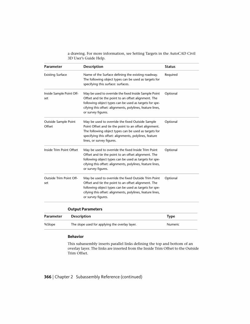
a drawing. For more information, see Setting Targets in the AutoCAD Civil3D User’s Guide Help.
StatusDescriptionParameter
RequiredName of the Surface defining the existing roadway.The following object types can be used as targets forspecifying this surface: surfaces.
Existing Surface
OptionalMay be used to override the fixed Inside Sample PointOffset and tie the point to an offset alignment. The
Inside Sample Point Off-set
following object types can be used as targets for spe-cifying this offset: alignments, polylines, feature lines,or survey figures.
OptionalMay be used to override the fixed Outside SamplePoint Offset and tie the point to an offset alignment.
Outside Sample PointOffset
The following object types can be used as targets forspecifying this offset: alignments, polylines, featurelines, or survey figures.
OptionalMay be used to override the fixed Inside Trim PointOffset and tie the point to an offset alignment. The
Inside Trim Point Offset
following object types can be used as targets for spe-cifying this offset: alignments, polylines, feature lines,or survey figures.
OptionalMay be used to override the fixed Outside Trim PointOffset and tie the point to an offset alignment. The
Outside Trim Point Off-set
following object types can be used as targets for spe-cifying this offset: alignments, polylines, feature lines,or survey figures.
Output Parameters
TypeDescriptionParameter
NumericThe slope used for applying the overlay layer.%Slope
Behavior
This subassembly inserts parallel links defining the top and bottom of anoverlay layer. The links are inserted from the Inside Trim Offset to the OutsideTrim Offset.
366 | Chapter 2 Subassembly Reference (continued)

Overlay Slopes
The slope of the Existing Surface is determined between the inside and outsidesample points. The slope of the overlay layer is determined by the followingsteps:
1 If the Overlay %Slope input is given as M, then the overlay slope matchesthe slope from the Inside Sample Point to the Outside Sample point.
2 If the Overlay %Slope is given as S, then the overlay uses the outside lanesuperelevation slope defined for the corridor alignment. The left sideslope is used if the Outside Sample Point is to the left of the Inside SamplePoint, otherwise the right side superelevation slope is used.
3 If a numeric value is given for the Overlay %Slope, the given value isused.
4 If a numeric value or the superelevation slope is used, the overlay slopeis compared to the existing slope between the sample points. If thedifference exceeds the Slope Tolerance value, the design slope is adjustedup or down by the Tolerance value to make it more closely match theexisting slope and minimize the amount of leveling or milling. Slopeadjustment does not occur if the Slope Tolerance is zero.
OverlayMillAndLevel1 | 367

Overlay Elevations
The elevations of the overlay points are determined as follows:
1 If the Use Profile value is True, the elevation of the corridor profile is heldat the Inside Trim offset on the top of overlay. The overlay is extendedat the overlay slope to the Outside Trim offset, and a parallel link isinserted for the bottom-of-overlay. Any areas above the existing surface
368 | Chapter 2 Subassembly Reference (continued)

and below the bottom-of-overlay are stored as closed shapes with code“Level”. Areas below the existing surface and above the bottom-of-overlayare stored as closed shapes with code “Mill”.
2 If the Use Profile value is False, the bottom-of-overlay link is shiftedvertically to hold to the Minimum Clearance above or below the existingsurface. A positive Minimum Clearance creates a leveling area above theexisting surface and below the bottom-of-overlay. A negative clearancecreates a milling area below the existing surface and above thebottom-of-overlay.
Minimum Clearance Point
The method of determining the point where the Minimum Clearanceappliesis shown in the diagram below.
1 A vertical projection line is established at any arbitrary offset.
2 Each point on the Existing Surface between the two trim points isprojected back to the projection line at the Overlay Slope.
3 The point with the highest elevation on the projection line is the controlpoint for a Minimum Clearance value greater than zero. The one withthe lowest is the control point for a Minimum Clearance value less thanzero.
Layout Mode Operation
In layout mode, this subassembly displays the overlay layer positioned fromany convenient point of attachment at a slope of -2%.
OverlayMillAndLevel1 | 369

Point, Link, and Shape CodesThe following table lists the point, link, and shape codes for this subassemblythat have codes assigned to them. Point, link, or shape codes for thissubassembly that do not have codes assigned are not included in this table.
DescriptionCodePoint, Link, or Shape
Overlay edges on finish gradeEOVP1, P2
Edges of bottom-of-overlayEOV_OverlayP3, P4
Top of overlayTop, PaveL1
Overlay links. Note that L3, L4 go from the bottom-of-overlay to top-of-overlay in both the Levelingand Milling cases
OverlayL2, L3, L4
For the Leveling caseLevelL5, L6For the Milling caseMill
Area between the top and bottom of overlay. Thisoverlaps the milling area (S3) for the Milling caseas shown in the Coding Diagram below.
OverlayS1
Area above existing surface and below the bottomof overlay (Leveling case)
LevelS2
Area below the existing surface and above thebottom of overlay (Milling case). This area overlaps
MillS3
the Overlay area as shown in the Coding Diagrambelow.
370 | Chapter 2 Subassembly Reference (continued)
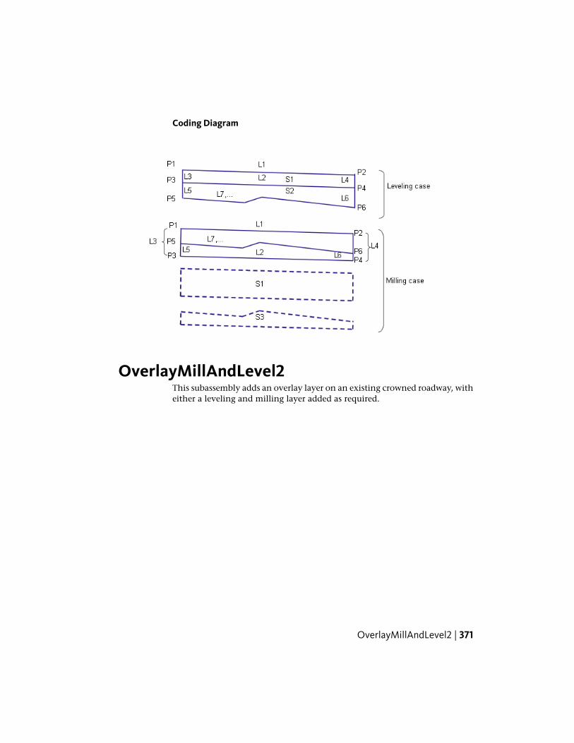
Coding Diagram
OverlayMillAndLevel2This subassembly adds an overlay layer on an existing crowned roadway, witheither a leveling and milling layer added as required.
OverlayMillAndLevel2 | 371

Attachment
The attachment point is the crown point on the overlay finish grade.
Input ParametersNote: All dimensions are in meters or feet unless otherwise noted. All slopesare in run-over-rise form (for example, 4 : 1) unless indicated as a percentslope with a “%” sign.
DefaultTypeDescriptionParameter
0.0NumericOffset of the crown point. The crown and samplepoints are used to calculate the left and right slopesof the existing roadway.
Crown Point Offset
0.0NumericOffset of the left sample pointLeft Sample PointOffset
0.0NumericOffset of the right sample pointRight Sample PointOffset
0.0NumericOffset of the left trim point, which defines theoutside edge of the overlay layer on the left side
Left Trim Point
372 | Chapter 2 Subassembly Reference (continued)

DefaultTypeDescriptionParameter
0.0NumericOffset of the right trim point, which defines theoutside edge of the overlay layer on the right side
Right Trim Point
Match slopeSelectionlist
Specifies the left overlay slope with the followingoptions: a) user defined, b) to match slope from
Left Overlay SlopeOptions
inside sample point to outside sample point or, c)use the outside lane superelevation slope of thebaseline alignment.
- 2.0 %Numeric,grade
Specifies user defined slope. Also can be used ifmatch points or superelevation slope doesn’t returnappropriate value.
Default Left OverlaySlope
Match slopeSelectionlist
Specifies the right overlay slope with the followingoptions: a) user defined, b) to match slope from
Right Overlay SlopeOptions
inside sample point to outside sample point or, c)use the outside lane superelevation slope of thebaseline alignment.
- 2.0 %Numeric,grade
Specifies user defined slope. Also can be used ifmatch points or superelevation slope doesn’t returnappropriate value.
Default Right OverlaySlope
0.5%Numeric,positive
The value that the Overlay Slopes are allowed varyfrom their design values. The slope tolerance is not
%Slope Tolerance
used if the Overlay Slope is given as M (see Beha-vior below for details).
Use minim-um clearance
SelectionList
Selects whether to hold the top of overlay at theinside trim point to the corridor profile elevation,
Use Profile
or to set the vertical placement of the overlay layerbased on the Minimum Clearance value
0.100 mNumericThe minimum vertical clearance between the exist-ing surface and the bottom of the overlay layer. A
Minimum Clearance(+/-) 0.30 ft
positive value places the bottom-of-overlay linkabove the existing surface, creating a Levelinglayer beneath the overlay. A negative value placesthe bottom-of-overlay link below the existing sur-face, creating a Milling layer that coincides with aportion of the Overlay layer.
OverlayMillAndLevel2 | 373
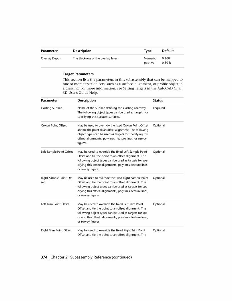
DefaultTypeDescriptionParameter
0.100 mNumeric,positive
The thickness of the overlay layerOverlay Depth0.30 ft
Target ParametersThis section lists the parameters in this subassembly that can be mapped toone or more target objects, such as a surface, alignment, or profile object ina drawing. For more information, see Setting Targets in the AutoCAD Civil3D User’s Guide Help.
StatusDescriptionParameter
RequiredName of the Surface defining the existing roadway.The following object types can be used as targets forspecifying this surface: surfaces.
Existing Surface
OptionalMay be used to override the fixed Crown Point Offsetand tie the point to an offset alignment. The following
Crown Point Offset
object types can be used as targets for specifying thisoffset: alignments, polylines, feature lines, or surveyfigures.
OptionalMay be used to override the fixed Left Sample PointOffset and tie the point to an offset alignment. The
Left Sample Point Offset
following object types can be used as targets for spe-cifying this offset: alignments, polylines, feature lines,or survey figures.
OptionalMay be used to override the fixed Right Sample PointOffset and tie the point to an offset alignment. The
Right Sample Point Off-set
following object types can be used as targets for spe-cifying this offset: alignments, polylines, feature lines,or survey figures.
OptionalMay be used to override the fixed Left Trim PointOffset and tie the point to an offset alignment. The
Left Trim Point Offset
following object types can be used as targets for spe-cifying this offset: alignments, polylines, feature lines,or survey figures.
OptionalMay be used to override the fixed Right Trim PointOffset and tie the point to an offset alignment. The
Right Trim Point Offset
374 | Chapter 2 Subassembly Reference (continued)

StatusDescriptionParameter
following object types can be used as targets for spe-cifying this offset: alignments, polylines, feature lines,or survey figures.
Output Parameters
TypeDescriptionParameter
NumericThe slope used for applying the overlay layer on the leftside
Left Overlay %Slope
NumericThe slope used for applying the overlay layer on the rightside
Right Overlay %Slope
Behavior
This subassembly inserts parallel links defining the top and bottom of anoverlay layer on each side that join at the crown point. The links are insertedfrom the Crown Point Offset to the Left and Right Trim Offsets.
Overlay Slopes
The slope of the Existing Surface on each side is determined betweenthe crownand sample points. The slopes of the overlay layers aredetermined by thefollowing steps:
1 If the Overlay %Slope input is given as M, then the overlay slope matchesthe slope from the Crown Point to the Sample point.
2 If the Overlay %Slope is given as S, then the overlay uses the outside lanesuperelevation slope defined for the corridor alignment.
3 If a numeric value is given for the Overlay %Slope, the given value isused.
4 If a numeric value or the superelevation slope is used, the overlay slopeis compared to the existing slope between the sample points. If thedifference exceeds the Slope Tolerance value, the design slope is adjustedup or down by the Tolerance value to make it more closely match theexisting slope and minimize the amount of leveling or milling. Slopeadjustment does not occur if the Slope Tolerance is zero.
OverlayMillAndLevel2 | 375

376 | Chapter 2 Subassembly Reference (continued)

Overlay Elevations
The elevations of the overlay points are determined as follows:
1 If the Use Profile value is True, the elevation of the corridor profile is heldat the Crown Point offset on the top of overlay. The overlay is extendedto each side at the overlay slopes to the Left and Right Trim offsets, andparallel links are inserted for the bottom-of-overlay. Any areas above theexisting surface and below the bottom-of-overlay are stored as closedshapes with code “Level”. Areas below the existing surface and above thebottom-of-overlay are stored as closed shapes with code “Mill”.
2 If the Use Profile value is False, the bottom-of-overlay link on each sideis shifted vertically to hold to the Minimum Clearance above or belowthe existing surface. A positive Minimum Clearance creates a levelingarea above the existing surface and below the bottom-of-overlay. Anegative clearance creates a milling area below the existing surface andabove the bottom-of-overlay. The overlay links on one side are shiftedvertically so that the links meet at the crown point.
Minimum Clearance Point
The method of determining the point where the Minimum Clearance appliesis shown in the diagram below.
1 A vertical projection line is established at any arbitrary offset.
2 Each point on the Existing Surface between the two trim points isprojected back to the projection line at the Overlay Slope.
OverlayMillAndLevel2 | 377

3 The point with the highest elevation on the projection line is the controlpoint for a Minimum Clearance value greater than zero. The one withthe lowest is the control point for a Minimum Clearance value less thanzero.
Layout Mode Operation
In layout mode, this subassembly displays the overlay layer positioned fromany convenient point of attachment at a slope of -2%.
Point, Link, and Shape CodesThe following table lists the point, link, and shape codes for this subassemblythat have codes assigned to them. Point, link, or shape codes for thissubassembly that do not have codes assigned are not included in this table.
DescriptionCodePoint, Link, or Shape
Crown on finish gradeCrownP1
Overlay edges on finish gradeEOVP2, P3
Crown on bottom-of-overlayCrown_OverlayP4
Edges of bottom-of-overlayEOV_OverlayP5, P6
Top of overlayTop, PaveL1, L2
Overlay links. Note that L5, L6 go from the bot-tom-of-overlay to top-of-overlay in both the Level-ing and Milling cases.
OverlayL3 – L6
378 | Chapter 2 Subassembly Reference (continued)
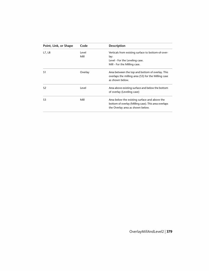
DescriptionCodePoint, Link, or Shape
Verticals from existing surface to bottom-of-over-lay:
LevelMill
L7, L8
Level - For the Leveling case.Mill - For the Milling case.
Area between the top and bottom of overlay. Thisoverlaps the milling area (S3) for the Milling caseas shown below.
OverlayS1
Area above existing surface and below the bottomof overlay (Leveling case)
LevelS2
Area below the existing surface and above thebottom of overlay (Milling case). This area overlapsthe Overlay area as shown below.
MillS3
OverlayMillAndLevel2 | 379

Coding Diagram
OverlayParabolicThis subassembly inserts parabolic travel lanes, to represent finish grade,pavement, and subbase for urban, parabolic lanes between known flangepoints. The parabolic shape is simulated by a series of short, straight-line links.
To use this subassembly, you should have separate alignments defining theleft and right flange points. Elevations at these points could come from surfacesor profiles. Furthermore, if the component defining the edges (for example,curb and gutter) is also a rehab component, then they could be passed in asmarked points, thus transferring offset and elevation information.
380 | Chapter 2 Subassembly Reference (continued)
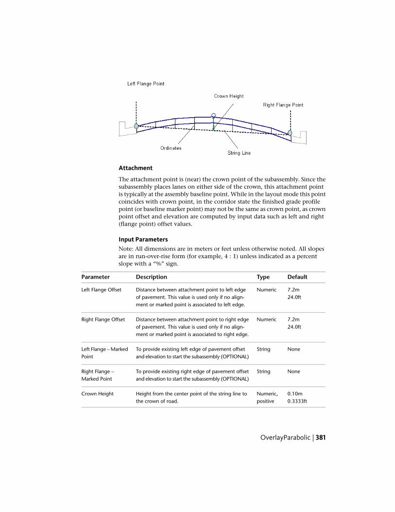
Attachment
The attachment point is (near) the crown point of the subassembly. Since thesubassembly places lanes on either side of the crown, this attachment pointis typically at the assembly baseline point. While in the layout mode this pointcoincides with crown point, in the corridor state the finished grade profilepoint (or baseline marker point) may not be the same as crown point, as crownpoint offset and elevation are computed by input data such as left and right(flange point) offset values.
Input ParametersNote: All dimensions are in meters or feet unless otherwise noted. All slopesare in run-over-rise form (for example, 4 : 1) unless indicated as a percentslope with a “%” sign.
DefaultTypeDescriptionParameter
7.2mNumericDistance between attachment point to left edgeof pavement. This value is used only if no align-ment or marked point is associated to left edge.
Left Flange Offset24.0ft
7.2mNumericDistance between attachment point to right edgeof pavement. This value is used only if no align-ment or marked point is associated to right edge.
Right Flange Offset24.0ft
NoneStringTo provide existing left edge of pavement offsetand elevation to start the subassembly (OPTIONAL)
Left Flange – MarkedPoint
NoneStringTo provide existing right edge of pavement offsetand elevation to start the subassembly (OPTIONAL)
Right Flange –Marked Point
0.10mNumeric,positive
Height from the center point of the string line tothe crown of road.
Crown Height0.3333ft
OverlayParabolic | 381

DefaultTypeDescriptionParameter
-1%NumericMinimum % cross slope allowed for the lanes, inthe outward direction from the attachment point.
Min %Slope
-4%NumericMaximum % cross slope allowed for the lanes, inthe outward direction from the attachment point.
Max %Slope
0.025mNumeric,positive
Depth of overlay below the finish grade.Overlay Depth0.083ft
8Numeric,positive,even
Number of straight line increments simulating theparabolic shape
No. Increments
If target parameters are provided, the parameters above (namely default offsetsand marked points) will be ignored as applicable.
Target ParametersThis section lists the parameters in this subassembly that can be mapped toone or more target objects, such as a surface, alignment, or profile object ina drawing. For more information, see Setting Targets in the AutoCAD Civil3D User’s Guide Help.
StatusDescriptionParameter
OptionalThis will provide left edge of pavement offset valuewith respect to the attachment point. The following
Left Gutter Point
object types can be used as targets for specifying thisoffset: alignments, polylines, feature lines, or surveyfigures.
OptionalThis will provide right edge of pavement offset valuewith respect to the attachment point. The following
Right Gutter Point
object types can be used as targets for specifying thisoffset: alignments, polylines, feature lines, or surveyfigures.
OptionalThis will provide left edge of pavement elevationvalue with respect to the attachment point. The fol-
Left Gutter Profile
lowing object types can be used as targets for specify-ing this elevation: profiles, 3D polylines, feature lines,or survey figures.
382 | Chapter 2 Subassembly Reference (continued)
StatusDescriptionParameter
OptionalThis will provide right edge of pavement elevationvalue with respect to the attachment point. The fol-
Right Gutter Profile
lowing object types can be used as targets for specify-ing this elevation: profiles, 3D polylines, feature lines,or survey figures.
RequiredIf profiles are not supplied for left/right edge ofpavement elevations, then this surface elevation at
EGTopSurf
that offset will be picked up as elevation value (forleft/right) respectively. The following object typescan be used as targets for specifying this surface:surfaces.
Output Parameters
None
Behavior
Initial attachment point is just a place holder (and more applicable in layoutmode). First two points to establish are left and right edges, whose offsets andelevations are determined based on input parameters.
Then a string line is defined by joining the left and right flange points (whichare newly established edges of travelways). This string line is divided by"number of increments" parameter and middle one is taken as "crown point"offset. Crown point elevation is established by adding the 'crown height"parameter to the elevation of midpoint on the string line.
The ordinates of the parabolic curve at other tesselated points are calculatedusing standard vertical curve equations, based on the assumption that thestring line is horizontal. Straight line links are added to connect the ordinatepoints in a series (from left edge to crown point to right edge) to define thefinish grade. A parallel surface is inserted at the overlay depth below this finishgrade.
Layout Mode Operation
In layout mode, this subassembly inserts equal number (based on inputparameter) lanes on either side of the attachment point. First two edge pointswill be located based on left/right offsets. These left and right point elevationsare calculated (in layout mode) by subtracting crown height from the ordinateof attachment point. Then the "Crown Point" is located halfway between these
OverlayParabolic | 383
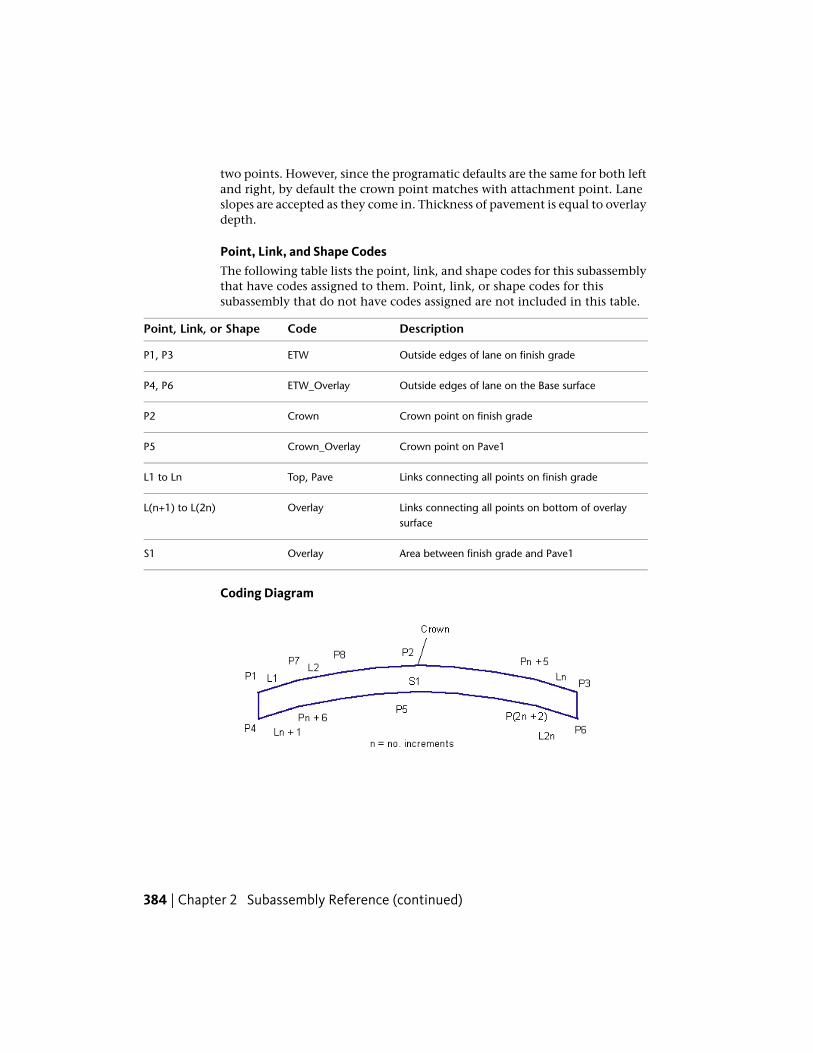
two points. However, since the programatic defaults are the same for both leftand right, by default the crown point matches with attachment point. Laneslopes are accepted as they come in. Thickness of pavement is equal to overlaydepth.
Point, Link, and Shape CodesThe following table lists the point, link, and shape codes for this subassemblythat have codes assigned to them. Point, link, or shape codes for thissubassembly that do not have codes assigned are not included in this table.
DescriptionCodePoint, Link, or Shape
Outside edges of lane on finish gradeETWP1, P3
Outside edges of lane on the Base surfaceETW_OverlayP4, P6
Crown point on finish gradeCrownP2
Crown point on Pave1Crown_OverlayP5
Links connecting all points on finish gradeTop, PaveL1 to Ln
Links connecting all points on bottom of overlaysurface
OverlayL(n+1) to L(2n)
Area between finish grade and Pave1OverlayS1
Coding Diagram
384 | Chapter 2 Subassembly Reference (continued)
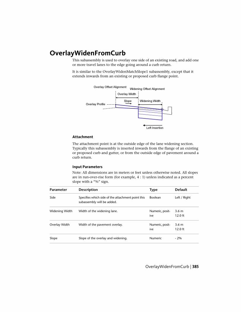
OverlayWidenFromCurbThis subassembly is used to overlay one side of an existing road, and add oneor more travel lanes to the edge going around a curb return.
It is similar to the OverlayWidenMatchSlope1 subassembly, except that itextends inwards from an existing or proposed curb flange point.
Attachment
The attachment point is at the outside edge of the lane widening section.Typically this subassembly is inserted inwards from the flange of an existingor proposed curb and gutter, or from the outside edge of pavement around acurb return.
Input ParametersNote: All dimensions are in meters or feet unless otherwise noted. All slopesare in run-over-rise form (for example, 4 : 1) unless indicated as a percentslope with a “%” sign.
DefaultTypeDescriptionParameter
Left / RightBooleanSpecifies which side of the attachment point thissubassembly will be added.
Side
3.6 mNumeric, posit-ive
Width of the widening lane.Widening Width12.0 ft
3.6 mNumeric, posit-ive
Width of the pavement overlay.Overlay Width12.0 ft
- 2%NumericSlope of the overlay and widening.Slope
OverlayWidenFromCurb | 385

DefaultTypeDescriptionParameter
0.025 mNumeric, posit-ive
Thickness of the Pave1 layer for the lane widen-ing; zero to omit.
Pave1 Depth0.083 ft
0.025 mNumeric, posit-ive
Thickness of the Pave2 layer for the lane widen-ing; zero to omit.
Pave2 Depth0.083 ft
0.100 mNumeric, posit-ive
Thickness of the base layer for the lane widening.Base Depth0.333 ft
0.300 mNumeric, posit-ive
Thickness of the subbase layer for the lanewidenin.
Subbase Depth1.0 ft
Target ParametersThis section lists the parameters in this subassembly that can be mapped toone or more target objects, such as a surface, alignment, or profile object ina drawing. For more information, see Setting Targets in the AutoCAD Civil3D User’s Guide Help.
StatusDescriptionParameter
RequiredName of the Surface defining the existing roadway.The following object types can be used as targetsfor specifying this surface: surfaces.
Existing Surface
OptionalMay be used to override the fixed Widening Widthand tie the inside edge of widening to an alignment.
Widening Offset
The following object types can be used as targetsfor specifying this offset: alignments, polylines, fea-ture lines, or survey figures.
OptionalMay be used to override the Overlay Width and tiethe inside edge of overlay to an alignment. The fol-
Offset Overlay
lowing object types can be used as targets for spe-cifying this offset: alignments, polylines, feature lines,or survey figures.
OptionalMay be used to override the Slope and tie the eleva-tion of the inside edge of overlay to a profile, result-
Overlay Profile
ing in a calculated slope. The following object typescan be used as targets for specifying this elevation:profiles, 3D polylines, feature lines, or survey figures.
386 | Chapter 2 Subassembly Reference (continued)

Output Parameters
TypeDescriptionParameter
NumericThe calculated slope on the existing surface from the SamplePoint to the Insert Point
%Slope
Behavior
The attachment point determines the offset and elevation of the outside edgeof widening. The location of the inside edge of widening and inside edge ofoverlay are determined using the given widths and slope. Alignments can beused to override the given numeric widths. If the Overlay Profile is given, thenthe slope is calculated between the profile elevation at the inside edge of theoverlay and the attachment point.
The following illustration shows a situation with an overlay offset profile. (Ifthe Overlay Profile is given, then the slope is calculated between the profileelevation at the inside edge of the overlay and the attachment point.)
This one below was imported at 150dpi.
The following illustration shows a situation with no overlay offset profile.
This one below was imported at 72dpi.
OverlayWidenFromCurb | 387
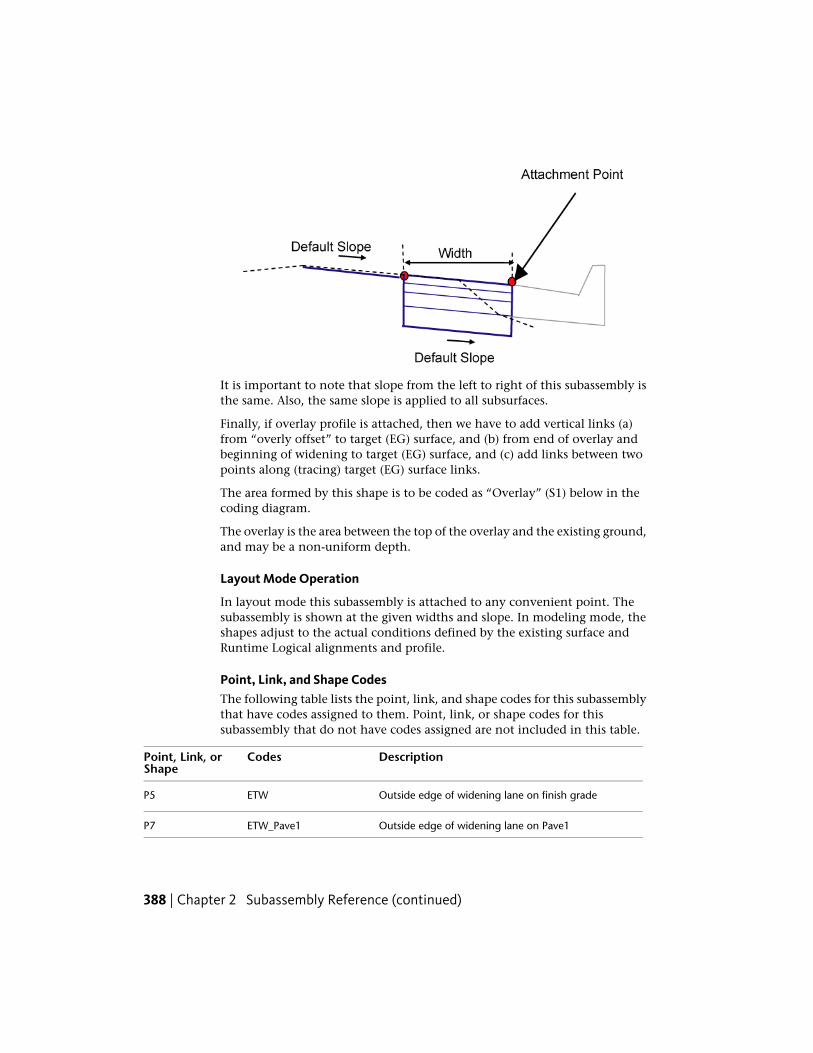
It is important to note that slope from the left to right of this subassembly isthe same. Also, the same slope is applied to all subsurfaces.
Finally, if overlay profile is attached, then we have to add vertical links (a)from “overly offset” to target (EG) surface, and (b) from end of overlay andbeginning of widening to target (EG) surface, and (c) add links between twopoints along (tracing) target (EG) surface links.
The area formed by this shape is to be coded as “Overlay” (S1) below in thecoding diagram.
The overlay is the area between the top of the overlay and the existing ground,and may be a non-uniform depth.
Layout Mode Operation
In layout mode this subassembly is attached to any convenient point. Thesubassembly is shown at the given widths and slope. In modeling mode, theshapes adjust to the actual conditions defined by the existing surface andRuntime Logical alignments and profile.
Point, Link, and Shape CodesThe following table lists the point, link, and shape codes for this subassemblythat have codes assigned to them. Point, link, or shape codes for thissubassembly that do not have codes assigned are not included in this table.
DescriptionCodesPoint, Link, orShape
Outside edge of widening lane on finish gradeETWP5
Outside edge of widening lane on Pave1ETW_Pave1P7
388 | Chapter 2 Subassembly Reference (continued)

DescriptionCodesPoint, Link, orShape
Outside edge of widening lane on Pave2ETW_Pave2P9
Outside edge of widening lane on BaseETW_BaseP11
Outside edge of widening lane on SubbaseETW_SubP13
Finish grade surfaceTop, PaveL1, L5
Superimposed over links on the Existing Surface. Note,there may be more than a single link between pointsP3 and P4.
OverlayL2
Pave1L6
Pave2L7
BaseL8
Subbase, DatumL9
DatumL10
Area between the overlay and existing lane.OverlayS1
Pave1S2
Pave2S3
BaseS4
SubbaseS5
OverlayWidenFromCurb | 389

Coding Diagram
OverlayWidenMatchSlope1This subassembly overlays one side of an existing road, and adds one or moretravel lanes to the edge while matching the existing lane slopes.
390 | Chapter 2 Subassembly Reference (continued)
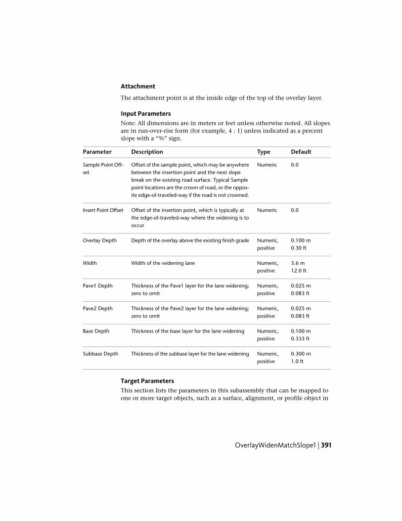
Attachment
The attachment point is at the inside edge of the top of the overlay layer.
Input ParametersNote: All dimensions are in meters or feet unless otherwise noted. All slopesare in run-over-rise form (for example, 4 : 1) unless indicated as a percentslope with a “%” sign.
DefaultTypeDescriptionParameter
0.0NumericOffset of the sample point, which may be anywherebetween the insertion point and the next slope
Sample Point Off-set
break on the existing road surface. Typical Samplepoint locations are the crown of road, or the oppos-ite edge-of-traveled-way if the road is not crowned.
0.0NumericOffset of the insertion point, which is typically atthe edge-of-traveled-way where the widening is tooccur
Insert Point Offset
0.100 mNumeric,positive
Depth of the overlay above the existing finish gradeOverlay Depth0.30 ft
3.6 mNumeric,positive
Width of the widening laneWidth12.0 ft
0.025 mNumeric,positive
Thickness of the Pave1 layer for the lane widening;zero to omit
Pave1 Depth0.083 ft
0.025 mNumeric,positive
Thickness of the Pave2 layer for the lane widening;zero to omit
Pave2 Depth0.083 ft
0.100 mNumeric,positive
Thickness of the base layer for the lane wideningBase Depth0.333 ft
0.300 mNumeric,positive
Thickness of the subbase layer for the lane wideningSubbase Depth1.0 ft
Target ParametersThis section lists the parameters in this subassembly that can be mapped toone or more target objects, such as a surface, alignment, or profile object in
OverlayWidenMatchSlope1 | 391

a drawing. For more information, see Setting Targets in the AutoCAD Civil3D User’s Guide Help.
StatusDescriptionParameter
RequiredName of the Surface defining the existing roadway.The following object types can be used as targets forspecifying this surface: surfaces.
Existing Surface
OptionalMay be used to override the fixed Sample Point Offsetand tie the point to an offset alignment. The following
Sample Point Offset
object types can be used as targets for specifying thisoffset: alignments, polylines, feature lines, or surveyfigures.
OptionalMay be used to override the fixed Insert Point Offsetand tie the point to an offset alignment. The following
Insert Point Offset
object types can be used as targets for specifying thisoffset: alignments, polylines, feature lines, or surveyfigures.
OptionalMay be used to override the fixed widening lane Widthand tie the edge-of-lane to an offset alignment. The
Width
following object types can be used as targets for spe-cifying this offset: alignments, polylines, feature lines,or survey figures.
Output Parameters
TypeDescriptionParameter
NumericThe calculated slope on the existing surface from the SamplePoint to the Insert Point
%Slope
Behavior
The elevations of the Sample Point and Insert Point on the Existing Surfaceare determined, and the slope is calculated from the sample point to the insertpoint. An overlay layer is added above the existing lane at the same slope forthe given Overlay Depth. A closed overlay shape is created by superimposingone or more links over the existing grade.The widening lane is attachedoutward from the overlay at the Insert Offset using the calculated slope.
392 | Chapter 2 Subassembly Reference (continued)
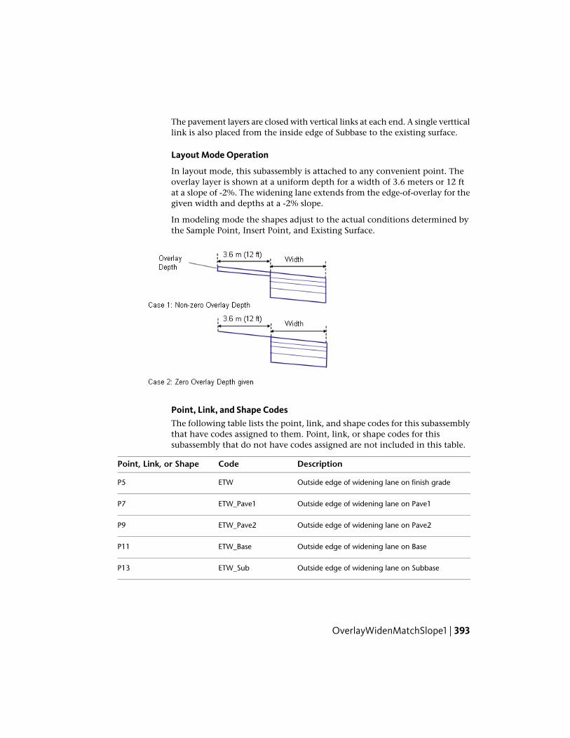
The pavement layers are closed with vertical links at each end. A single vertticallink is also placed from the inside edge of Subbase to the existing surface.
Layout Mode Operation
In layout mode, this subassembly is attached to any convenient point. Theoverlay layer is shown at a uniform depth for a width of 3.6 meters or 12 ftat a slope of -2%. The widening lane extends from the edge-of-overlay for thegiven width and depths at a -2% slope.
In modeling mode the shapes adjust to the actual conditions determined bythe Sample Point, Insert Point, and Existing Surface.
Point, Link, and Shape CodesThe following table lists the point, link, and shape codes for this subassemblythat have codes assigned to them. Point, link, or shape codes for thissubassembly that do not have codes assigned are not included in this table.
DescriptionCodePoint, Link, or Shape
Outside edge of widening lane on finish gradeETWP5
Outside edge of widening lane on Pave1ETW_Pave1P7
Outside edge of widening lane on Pave2ETW_Pave2P9
Outside edge of widening lane on BaseETW_BaseP11
Outside edge of widening lane on SubbaseETW_SubP13
OverlayWidenMatchSlope1 | 393
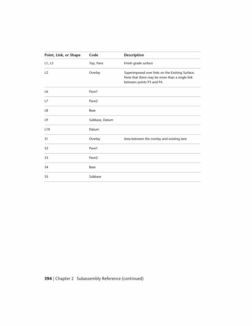
DescriptionCodePoint, Link, or Shape
Finish grade surfaceTop, PaveL1, L5
Superimposed over links on the Existing Surface.Note that there may be more than a single linkbetween points P3 and P4.
OverlayL2
Pave1L6
Pave2L7
BaseL8
Subbase, DatumL9
DatumL10
Area between the overlay and existing laneOverlayS1
Pave1S2
Pave2S3
BaseS4
SubbaseS5
394 | Chapter 2 Subassembly Reference (continued)

Coding Diagram
OverlayWidenMatchSlope2This subassembly overlays an existing uncrowned road, and adds one or moretravel lanes to the left and right edges while matching the existing lane slope.
OverlayWidenMatchSlope2 | 395

Attachment
The attachment point is at the inside edges of the finish grade on the wideninglanes.
Input ParametersNote: All dimensions are in meters or feet unless otherwise noted. All slopesare in run-over-rise form (for example, 4 : 1) unless indicated as a percentslope with a “%” sign.
DefaultTypeDescriptionParameter
0.0NumericOffset of the Left Insert Point. This is the point wherethe widening lane on the left begins, and is typicallyat the existing left edge-of-traveled-way.
Left Insert PointOffset
0.0NumericOffset of the Right Insert Point, typically at the exist-ing right edge-of-traveled way
Right Insert PointOffset
0.100 mNumeric,positive
Depth of the overlay above the existing finish gradeOverlay Depth0.30 ft
396 | Chapter 2 Subassembly Reference (continued)
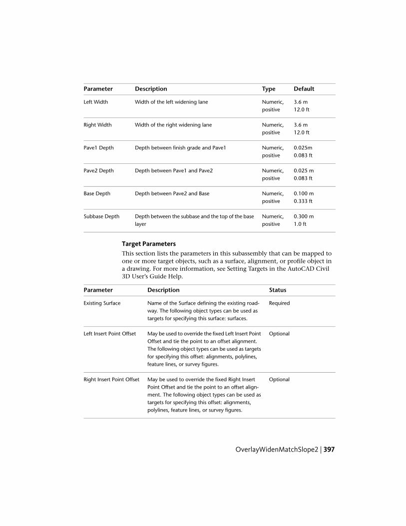
DefaultTypeDescriptionParameter
3.6 mNumeric,positive
Width of the left widening laneLeft Width12.0 ft
3.6 mNumeric,positive
Width of the right widening laneRight Width12.0 ft
0.025mNumeric,positive
Depth between finish grade and Pave1Pave1 Depth0.083 ft
0.025 mNumeric,positive
Depth between Pave1 and Pave2Pave2 Depth0.083 ft
0.100 mNumeric,positive
Depth between Pave2 and BaseBase Depth0.333 ft
0.300 mNumeric,positive
Depth between the subbase and the top of the baselayer
Subbase Depth1.0 ft
Target ParametersThis section lists the parameters in this subassembly that can be mapped toone or more target objects, such as a surface, alignment, or profile object ina drawing. For more information, see Setting Targets in the AutoCAD Civil3D User’s Guide Help.
StatusDescriptionParameter
RequiredName of the Surface defining the existing road-way. The following object types can be used astargets for specifying this surface: surfaces.
Existing Surface
OptionalMay be used to override the fixed Left Insert PointOffset and tie the point to an offset alignment.
Left Insert Point Offset
The following object types can be used as targetsfor specifying this offset: alignments, polylines,feature lines, or survey figures.
OptionalMay be used to override the fixed Right InsertPoint Offset and tie the point to an offset align-
Right Insert Point Offset
ment. The following object types can be used astargets for specifying this offset: alignments,polylines, feature lines, or survey figures.
OverlayWidenMatchSlope2 | 397

StatusDescriptionParameter
OptionalMay be used to override the fixed Left Width andtie the edge-of-lane to an offset alignment. The
Left Width
following object types can be used as targets forspecifying this offset: alignments, polylines, fea-ture lines, or survey figures.
OptionalMay be used to override the fixed Right Widthand tie the edge-of-lane to an offset alignment.
Right Width
The following object types can be used as targetsfor specifying this offset: alignments, polylines,feature lines, or survey figures.
Output Parameters
TypeDescriptionParameter
NumericThe calculated slope on the existing surface from theSample Point to the Insert Point
%Slope
Behavior
The elevations of the Left and Right Insert Points on the Existing Surface aredetermined, and the slope is calculated between the two points. If a non-zeroOverlay Depth is given, an overlay layer is added above the existing lane atthe calculated slope. A closed overlay shape is created by superimposing oneor more links over the existing grade. The widening lanes are inserted outwardfrom the overlay edges for the given widths at calculated slope.
If the Overlay Depth is given as zero, the widening lanes are inserted outwardfrom the insert offsets at the existing grade.
The pavement layers are closed with vertical links at each end. A single vertticallink is also placed from the inside edge of Subbase to the existing surface.
Layout Mode Operation
In layout mode, this subassembly is attached to any convenient point. Theoverlay layer is shown at a uniform depth for a width of 4.2 meters or 14 feetat a slope of -2%. The widening lanes extend from the edges-of-overlay at thegiven widths and depths at the -2% slope.
In modeling mode the subassembly adjusts to the positions and slopesdetermined by the Insert Points and the Existing Surface.
398 | Chapter 2 Subassembly Reference (continued)
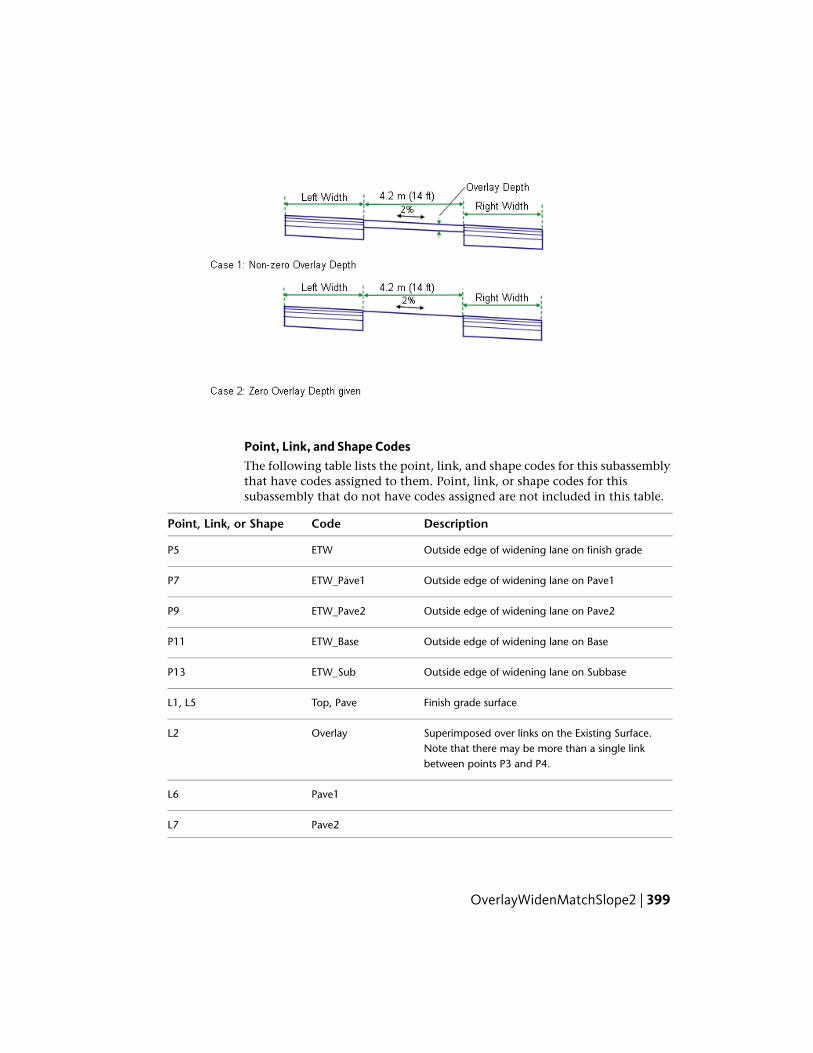
Point, Link, and Shape CodesThe following table lists the point, link, and shape codes for this subassemblythat have codes assigned to them. Point, link, or shape codes for thissubassembly that do not have codes assigned are not included in this table.
DescriptionCodePoint, Link, or Shape
Outside edge of widening lane on finish gradeETWP5
Outside edge of widening lane on Pave1ETW_Pave1P7
Outside edge of widening lane on Pave2ETW_Pave2P9
Outside edge of widening lane on BaseETW_BaseP11
Outside edge of widening lane on SubbaseETW_SubP13
Finish grade surfaceTop, PaveL1, L5
Superimposed over links on the Existing Surface.Note that there may be more than a single linkbetween points P3 and P4.
OverlayL2
Pave1L6
Pave2L7
OverlayWidenMatchSlope2 | 399

DescriptionCodePoint, Link, or Shape
BaseL8
Subbase, DatumL9
DatumL10
Area between the overlay and existing laneOverlayS1
Pave1S2
Pave2S3
BaseS4
SubbaseS5
Coding Diagram
400 | Chapter 2 Subassembly Reference (continued)

OverlayWidenWithSuper1This subassembly overlays one side of an existing road, and adds one or moretravel lanes to the edge using the superelevation slope defined for the outsidetravel lane.
Attachment
The attachment point is at the inside edge of the top of the overlay layer ifthe Overlay Depth is non-zero, or at the inside edge on finish grade of thewidening lane if the Overlay Depth is zero.
Input ParametersNote: All dimensions are in meters or feet unless otherwise noted. All slopesare in run-over-rise form (for example, 4 : 1) unless indicated as a percentslope with a “%” sign.
DefaultTypeDescriptionParameter
0.0NumericOffset of the control point, which defines the begin-ning of the pavement overlay layer
Control Point Offset
0.0NumericOffset of the insertion point of the widening lane,which is typically at the existing edge-of-traveled-
Insert Point Offset
way. Specifying a positive value for the this para-meter inserts this subassembly on the right side ofa corridor, or controlling baseline. A negative value
OverlayWidenWithSuper1 | 401

DefaultTypeDescriptionParameter
inserts it on the left side. For more information, see"Inserting Subassemblies on Right and Left Sidesof a Corridor" in the Corridors chapter of theAutoCAD Civil 3D User's Guide Help.
0.100 mNumeric,positive
Depth of the overlay above the existing finish gradeat the control point.
Overlay Depth0.30 ft
3.6 mNumeric,positive
Width of the widening laneWidth12.0 ft
0.025 mNumeric,positive
Thickness of the Pave1 layer for the lane widening;zero to omit
Pave1 Depth0.083 ft
0.025 mNumeric,positive
Thickness of the Pave2 layer for the lane widening;zero to omit
Pave2 Depth0.083 ft
0.100 mNumeric,positive
Thickness of the base layer for the lane wideningBase Depth0.333 ft
0.300 mNumeric,positive
Thickness of the subbase layer for the lane wideningSubbase Depth1.0 ft
Target ParametersThis section lists the parameters in this subassembly that can be mapped toone or more target objects, such as a surface, alignment, or profile object ina drawing. For more information, see Setting Targets in the AutoCAD Civil3D User’s Guide Help.
StatusDescriptionParameter
RequiredName of the Surface defining the existingroadway. The following object types can be
Existing Surface
used as targets for specifying this surface: sur-faces.
OptionalMay be used to override the fixed Control PointOffset and tie the point to an offset alignment.
Control Point Offset
The following object types can be used as tar-gets for specifying this offset: alignments,polylines, feature lines, or survey figures.
402 | Chapter 2 Subassembly Reference (continued)

StatusDescriptionParameter
OptionalMay be used to override the fixed Insert PointOffset and tie the point to an offset alignment.
Insert Point Offset
The following object types can be used as tar-gets for specifying this offset: alignments,polylines, feature lines, or survey figures.
OptionalMay be used to override the fixed wideninglane Width and tie the edge-of-lane to an offset
Width
alignment. The following object types can beused as targets for specifying this offset: align-ments, polylines, feature lines, or survey figures.
Output Parameters
TypeDescriptionParameter
NumericThe calculated slope on the existing surface from the SamplePoint to the Insert Point
%Slope
Behavior
The outside lane superelevation is obtained from the alignment properties ofthe current control alignment, and the elevation on the Existing Surface atthe Control Point Offset is determined.
If a non-zero Overlay Depth is given, the overlay depth is applied at the controlpoint. The top of the overlay layer extends to the Insert Point Offset at thesuperelevation slope, and the overlay shape is closed by superimposing linksover the Existing Surface between the control and insert points and addingvertical links at each end. The widening lane is extended outward at thesuperelevation slope for the given Width from the edge of the overlay surface.
If the Overlay Depth is zero, the widening lane extends outward from theInsert Point Offset on the Existing Surface at the superelevation slope for thegiven Width.
The pavement layers are closed with vertical links at each end. A single vertticallink is also placed from the inside edge of Subbase to the existing surface.
Layout Mode Operation
In layout mode, this subassembly may be attached to any convenient point.The overlay layer is shown at a uniform depth, with a width of 3.6 meters or
OverlayWidenWithSuper1 | 403

12 feet and extended at a slope of -2%. If the Overlay Depth is zero, the overlayis shown as a single link. The widening lane extends from the edge-of-overlayat a slope of -2%.
When used in corridor modeling mode, the shapes adjust to the selectedcontrol point, insert point, superelevation slope, and existing surface.
Point, Link, and Shape CodesThe following table lists the point, link, and shape codes for this subassemblythat have codes assigned to them. Point, link, or shape codes for thissubassembly that do not have codes assigned are not included in this table.
DescriptionCodePoint, Link, or Shape
Outside edge of widening lane on finish gradeETWP5
Outside edge of widening lane on Pave1ETW_Pave1P7
Outside edge of widening lane on Pave2ETW_Pave2P9
Outside edge of widening lane on BaseETW_BaseP11
Outside edge of widening lane on SubbaseETW_SubP13
Finish grade surfaceTop, PaveL1, L5
404 | Chapter 2 Subassembly Reference (continued)

DescriptionCodePoint, Link, or Shape
Superimposed over links on the Existing Surface.Note that there may be more than a single linkbetween points P3 and P4.
OverlayL2
Pave1L6
Pave2L7
BaseL8
Subbase, DatumL9
DatumL10
Area between the overlay and existing lane.OverlayS1
Pave1S2
Pave2S3
BaseS4
SubbaseS5
OverlayWidenWithSuper1 | 405

Coding Diagram
406 | Chapter 2 Subassembly Reference (continued)

Subassembly Reference(continued)
The subassemblies in this subassembly reference are organized alphabetically into the followingsections:
■ Subassembly Reference - Introduction through LaneTowardCrown (page 1)
■ Subassembly Reference (continued) - LinkMulti through OverlayWidenWithSuper1 (page257)
■ Subassembly Reference (continued) - RailSingle through UrbanSidewalk (this section)
RailSingleThis subassembly inserts the rails, sleeper, ballast, and sub-ballast for asingle-track railroad.
It should be followed with a Daylight subassembly on the left and right sidesto close to existing ground in cut and fill situations.
3
407

NOTE This subassembly is designed for visualization and to demonstrate the useof corridor modeling for rail applications. It is not intended for actual engineeringproduction work.
Attachment
The attachment point is at a distance equal to the rail height above thecenterline of the sleeper.
Input ParametersNote: All dimensions are in meters or feet unless otherwise noted. All slopesare in run-over-rise form (for example, 4 : 1) unless indicated as a percentslope with a “%” sign.
DefaultTypeDescriptionParameter
0 (%)Numeric% slope of the roadbedRail % Slope
1.435 mNumeric,positive
Width of the rail gauge from inside-to-in-side rail. The rails are placed symetricallyabout the centerline alignment.
Gauge Width4.7083 ft (4’ 8-1/2”)
2.4 mNumeric,positive
Width of the sleeper, placed symetricallyabout the centerline
Sleeper Width8.0 ft
0.200 mNumeric,positive
Height of the sleeperSleeper Height0.67 ft
3.6 mNumeric,positive
Width of the top of the ballast layer, placedsymetrically about the centerline
Ballast Width12.0 ft
0.3Numeric,positive
Thickness of the ballast layer from finishgrade
Ballast Depth1.0 ft
2 (: 1)Numeric,positive
Side slope (x : 1) of the ballast layerBallast Side Slope
6.6 mNumeric,positive
Width of the top of the sub-ballast layer,placed symetrically about the centerline
Sub-ballast Width22.0 ft
0.3Numeric,positive
Thickness of the sub-ballast layerSub-ballast Depth1.0 ft
408 | Chapter 3 Subassembly Reference (continued)

DefaultTypeDescriptionParameter
2 (: 1)Numeric,positive
Side slope of the sub-ballast layerSub-ballast SideSlope
Target Parameters
This section lists the parameters in this subassembly that can be mapped toone or more target objects, such as a surface, alignment, or profile object ina drawing. For more information, see Setting Targets in the AutoCAD Civil3D User’s Guide Help.
Target Parameters: None.
Output Parameters
None.
Behavior
The links for the rails, sleeper, ballast, and sub-ballast are calculated and placedbased on the input parameter values provided. If the Rail %Slope is non-zero,the corridor profile elevation is held at the center of the rail on the low side.The finish grade, sleeper, ballast, and sub-ballast links are maintained at theRail %Slope.
Layout Mode Operation
In layout mode, this subassembly displays the links comprising the finishgrade, ballast, sub-ballast, and side slopes.
RailSingle | 409
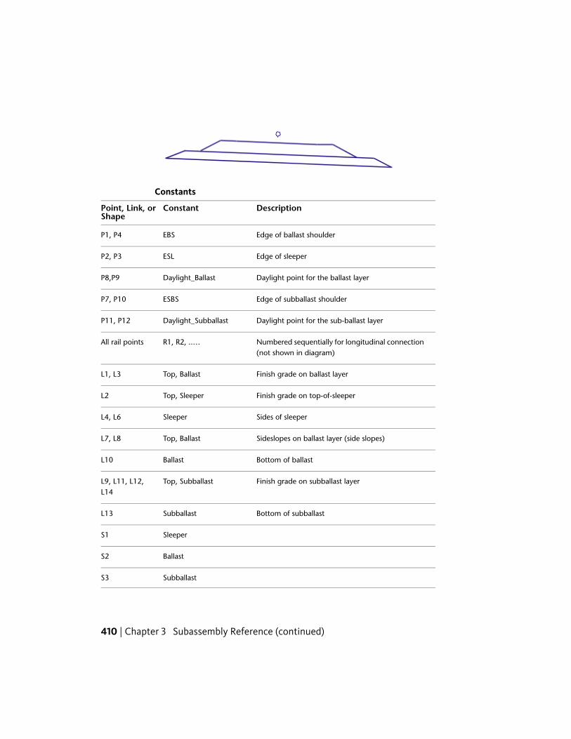
Constants
DescriptionConstantPoint, Link, orShape
Edge of ballast shoulderEBSP1, P4
Edge of sleeperESLP2, P3
Daylight point for the ballast layerDaylight_BallastP8,P9
Edge of subballast shoulderESBSP7, P10
Daylight point for the sub-ballast layerDaylight_SubballastP11, P12
Numbered sequentially for longitudinal connection(not shown in diagram)
R1, R2, ..…All rail points
Finish grade on ballast layerTop, BallastL1, L3
Finish grade on top-of-sleeperTop, SleeperL2
Sides of sleeperSleeperL4, L6
Sideslopes on ballast layer (side slopes)Top, BallastL7, L8
Bottom of ballastBallastL10
Finish grade on subballast layerTop, SubballastL9, L11, L12,L14
Bottom of subballastSubballastL13
SleeperS1
BallastS2
SubballastS3
410 | Chapter 3 Subassembly Reference (continued)
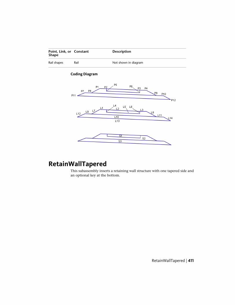
DescriptionConstantPoint, Link, orShape
Not shown in diagramRailRail shapes
Coding Diagram
RetainWallTaperedThis subassembly inserts a retaining wall structure with one tapered side andan optional key at the bottom.
RetainWallTapered | 411
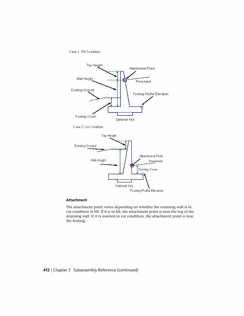
Attachment
The attachment point varies depending on whether the retaining wall is incut condition or fill. If it is in fill, the attachment point is near the top of theretaining wall. If it is inserted in cut condition, the attachment point is nearthe footing.
412 | Chapter 3 Subassembly Reference (continued)

Input Parameters
Note: All dimensions are in meters or feet unless otherwise noted. All slopesare in run-over-rise form (for example, 4 : 1), unless indicated as a percentslope with a “%” sign.
DefaultTypeDescriptionParameter
RightLeft / RightSpecifes to insert the sub-assembly either on the right
Side
or the left side of the attach-ment point.
0.958 ftNumericSpecifies the width of thewall at the top
Wall Top Width0.292 m
1.320 ftNumericThe distance between thetop-of-the wall and the
Top Height0.40 m
hook in fill or the new hookin cut.
1.667 ftNumericThe depth of cover from thetop-of-footing to the finish
Footing Cover0.50 m
grade line on the back sideof the wall in fill or to thehook when in cut.
YesBooleanSpecies to add an optionalkey below the footing
Key
Wall height is determined from the top of the footing to the insertion pointof the ground elevation on the vertical face, whichever is higher. Wall batteredslope, width of the footing, offset of wall vertical face, optional key dimensions,and the location of the key center, are all functions of the wall height.
Target ParametersThis section lists the parameters in this subassembly that can be mapped toone or more target objects, such as a surface, alignment, or profile object in
RetainWallTapered | 413

a drawing. For more information, see Setting Targets in the AutoCAD Civil3D User’s Guide Help.
StatusDescriptionParameter
OptionalMay be used to override the fixed wall height and tie toa profile. The following object types can be used as targets
Wall Height
for specifying this elevation: profiles, 3D polylines, featurelines, or survey figures.
RequiredExisting ground surface name to determine retaining wallin cut or fill. The following object types can be used astargets for specifying this surfaces: surfaces.
Target Surface
Output Parameters
None.
Behavior
This subassembly can be inserted on either the left or the right sides. Theattachment point is different for the fill or cut condition. In fill, the attachmentpoint is assumed to be where the finish grade intersects the inside face of thewall, at a distance of Top Height below the top of the wall. In cut, theattachment point is assumed to be where the finish grade intersects the insideface, at a distance of Footing Cover above the top-of-footing. The wall heightis determined from the Wall Height or Profile input.
In fill, the sloping wall face is toward the center of the roadway. In cut, thesloping wall face is away from the roadway. If the Key option is set to No,then the base of the footing is a single horizontal link. If the Key option isused, links to define the optional Key are inserted.
Layout Mode Operation
In layout mode, the subassembly draws the retaining wall shape as specifiedby the input parameter values, assuming that the subassembly is in a fillcondition.
414 | Chapter 3 Subassembly Reference (continued)
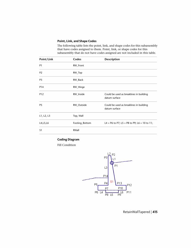
Point, Link, and Shape CodesThe following table lists the point, link, and shape codes for this subassemblythat have codes assigned to them. Point, link, or shape codes for thissubassembly that do not have codes assigned are not included in this table.
DescriptionCodesPoint/Link
RW_FrontP1
RW_TopP2
RW_BackP3
RW_HingeP14
Could be used as breaklines in buildingdatum surface
RW_InsideP12
Could be used as breaklines in buildingdatum surface
RW_OutsideP5
Top, WallL1, L2, L3
L4 = P6 to P7; L5 = P8 to P9; L6 = 10 to 11;Footing_BottomL4,L5,L6
RWallS1
Coding Diagram
Fill Condition
RetainWallTapered | 415

Cut Condition
RetainWallTaperedWideThis subassembly inserts a retaining wall structure with one side tapered, andis typically used if walls are 5.5 meters or higher.
416 | Chapter 3 Subassembly Reference (continued)

This subassembly also adds an optional key at the bottom.
Attachment
The attachment point varies depending on whether the retaining wall is in acut or fill condition. If it is in a fill condition, the attachment point is nearthe top of the retaining wall. In a cut condition, the attachment point is nearthe footing.
Input Parameters
Note: All dimensions are in meters or feet unless otherwise noted. All slopesare in run-over-rise form (for example, 4 : 1), unless indicated as a percentslope with a “%” sign.
DefaultTypeDescriptionParameter
RightLeft / RightSpecifes to insert the subassembly either onthe right or the left side of the attachmentpoint.
Side
1.476 ftNumericSpecifies the width of the wall at the topWall Top Width0.450 m
1.320 ftNumericthe distance between the top-of-the walland the hook in fill or the new hook in cut.
Top Height0.40 m
RetainWallTaperedWide | 417

DefaultTypeDescriptionParameter
1.667 ftNumericThe depth of cover from the top-of-footingto the finish grade line on the back side ofthe wall in fill or to the hook when in cut.
Footing Cover0.50 m
YesBooleanSpecies to add an optional key below thefooting
Key
Wall height is determined from the top of the footing to the attachment pointof ground elevation on the vertical face, whichever is higher. Width and depthof the footing are measured as a function of the wall height. Wall vertical faceis located at ¼ of the footing width, and the bottom of battered slope is at300 mm from the other edge. Optional key is locate right at the center of thefooting at 300mm deep and 600mm wide.
Target ParametersThis section lists the parameters in this subassembly that can be mapped toone or more target objects, such as a surface, alignment, or profile object ina drawing. For more information, see Setting Targets in the AutoCAD Civil3D User’s Guide Help.
StatusDescriptionParameter
OptionalMay be used to override the fixed wall height and tieto a profile. The following object types can be used
Wall Height
as targets for specifying this elevation: profiles, 3Dpolylines, feature lines, or survey figures.
RequiredExisting ground surface name to determine retainingwall in cut or fill. The following object types can beused as targets for specifying this surfaces: surfaces.
Target Surface
Output Parameters
None.
Behavior
This subassembly can be inserted on either the left or the right sides. Theattachment point is different for the fill or cut condition. In fill, the attachmentpoint is assumed to be where the finish grade intersects the inside face of thewall, at a distance below the top of the wall equal to the Top Height parameter.In a cut condition, the attachment point is assumed to be where the finish
418 | Chapter 3 Subassembly Reference (continued)

grade intersects the inside face, above the top-of-footing at a distance equalto the Footing Cover parameter. The wall height is determined from the WallHeight or Profile input.
In a fill condition, the sloping wall face is toward the center of the roadway.In a cut condition, the sloping wall face is away from the roadway, towardthe earth being retained. If the Key option is set to No, then the base of thefooting is a single horizontal link. If the Key option is used, links to definethe optional key are created.
Layout Mode Operation
In layout mode, the subassembly draws the retaining wall shape as specifiedby the input parameter values, assuming that the subassembly is in a fillcondition.
Point, Link, and Shape CodesThe following table lists the point, link, and shape codes for this subassemblythat have codes assigned to them. Point, link, or shape codes for thissubassembly that do not have codes assigned are not included in this table.
DescriptionCodesPoint/Link
RW_FrontP1
RW_TopP2
RW_BackP3
RW_HingeP14
Could be used as breaklines in build-ing datum surface
RW_InsideP12
Could be used as breaklines in build-ing datum surface
RW_OutsideP5
L1=P1 to P2; L2= P2 to P3; L3 = P3to P14;
Top, WallL1, L2, L3
L4 = P6 to P7; L5 = P8 to P9; L6 = 10to 11;
Footing_BottomL4,L5,L6
RWallS1
RetainWallTaperedWide | 419

Coding Diagram
Fill Condition
Cut Condition
RetainWallTieToDitchThis subassembly inserts a retaining wall structure with a paved shoulder andwith special tie slopes to tie to an existing ditch.
420 | Chapter 3 Subassembly Reference (continued)
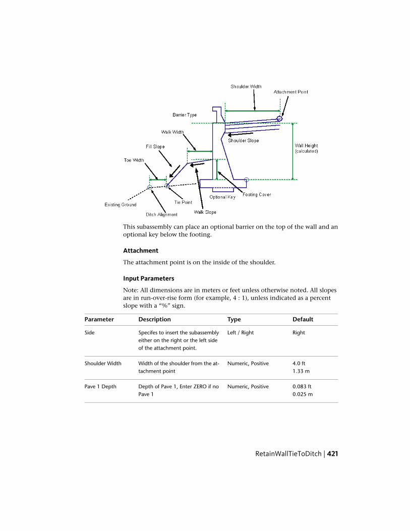
This subassembly can place an optional barrier on the top of the wall and anoptional key below the footing.
Attachment
The attachment point is on the inside of the shoulder.
Input Parameters
Note: All dimensions are in meters or feet unless otherwise noted. All slopesare in run-over-rise form (for example, 4 : 1), unless indicated as a percentslope with a “%” sign.
DefaultTypeDescriptionParameter
RightLeft / RightSpecifes to insert the subassemblyeither on the right or the left sideof the attachment point.
Side
4.0 ftNumeric, PositiveWidth of the shoulder from the at-tachment point
Shoulder Width1.33 m
0.083 ftNumeric, PositiveDepth of Pave 1, Enter ZERO if noPave 1
Pave 1 Depth0.025 m
RetainWallTieToDitch | 421

DefaultTypeDescriptionParameter
0.083 ftNumeric, PositiveDepth of Pave 2, Enter ZERO if noPave 2
Pave 2 Depth0.025 m
0.333 ftNumeric, positiveDepth of base layerBase Depth0.1 m
0.3 mNumeric, positiveDepth of the subbase layer.Subbase Depth1.0 ft
0.958 ftNumericSpecifies the width of the wall.Wall Width0.292 m
1.667 ftNumericThe depth of cover from the top-of-footing to the finish grade line
Footing Cover0.50 m
on the back side of the wall in fillor to the hook when in cut.
YesBooleanSpecies to add an optional key be-low the footing
Key
YesString, (a) Yes, (b) NoSpecifies to use a barrier on the topof the wall
Use Barrier
NoList of option: a) No, b)Outside shoulder slope,c) Inside shoulder slope.
Specifies to use the slope from thesuperelevation specification definedon the baseline alignment.
Use SuperelevationSlope
- 2.0%Numeric, PositiveDefault cross slope of the shapesurface. The value is used if the su-
Default ShoulderSlope
perelevation slope is not used or isnot specified for the baselinealignment.
3.300 ftNumeric, PositiveWidth of the walkway link on thetie slope
Walk Width1.0 m
25 %NumericSlope of the walkway link(grade/slope type)
Walk Slope
2.00 : 1NumericSlope of the fill link from the walk-way to the tie point (Slope type)
Fill Slope
422 | Chapter 3 Subassembly Reference (continued)

DefaultTypeDescriptionParameter
1.670 ftNumeric, PositiveWidth from ditch point to the tiepoint (to existing inside edge ofthe ditch)
Toe Width0.5 m
Wall height is determined from top of the footing to attachment point ofground elevation on the vertical face, whichever is higher. Wall battered slope,width of the footing, offset of wall vertical face, optional key dimensions, andthe location of the key center are all functions of the wall height.
Target ParametersThis section lists the parameters in this subassembly that can be mapped toone or more target objects, such as a surface, alignment, or profile object ina drawing. For more information, see Setting Targets in the AutoCAD Civil3D User’s Guide Help.
StatusDescriptionParameter
OptionalMay be used to override the shoulder slope by tieingto a profile. The following object types can be used
Edge of Shoulder
as targets for specifying this elevation: profiles, 3Dpolylines, feature lines, or survey figures.
RequiredInside edge of ditch profile used to locate Tie Point.The following object types can be used as targets for
Ditch Offset
specifying this offset: alignments, polylines, featureslines, or survey figures.
RequiredExisting ground surface to tie in with respect to spe-cified ditch and toe width. The following object types
Tie-in Surface
can be used as targets for specifying this surfaces:surfaces.
Output Parameters
None.
Behavior
This subassembly can be inserted either on the left or the right sides. Theattachment point is assumed to be at the design edge-of-traveled-way, fromwhere the paved shoulders will be drawn as specified by this subassembly.
RetainWallTieToDitch | 423

The top-of-footing elevation is determined by working inwards from the TiePoint to the inside edge of walkway, then subtracting the Footing Cover fromthe tie link at the offset of the outside footing corner. The height of wall (H)is calculated between the Outside Edge of the Shoulder and the top of footing.If the Key option is set to No, then the base of the footing is a single horizontallink. If the Key option is used, links to define the optional key are inserted.
Note: A very small gap (0.001 for m) is left between the pavement layers andthe inside face of wall. This is to facilitate material analysis using the quantitytakeoff feature, as shown in the detail below.
Layout Mode Operation
In layout mode, the subassembly draws the retaining wall shape as specifiedby the input parameter values, assuming that the subassembly is in a fillcondition.
Point, Link, and Shape CodesThe following table lists the point, link, and shape codes for this subassemblythat have codes assigned to them. Point, link, or shape codes for thissubassembly that do not have codes assigned are not included in this table.
DescriptionCodesPoint/Link
DaylightP2
Edge of the walk widthWalk_EdgeP3
RW_HingeP14
Could be used as breaklines in buildingdatum surface
RW_InsideP12
Could be used as breaklines in buildingdatum surface
RW_OutsideP5
424 | Chapter 3 Subassembly Reference (continued)

DescriptionCodesPoint/Link
TopL1, L2, L3
WallL2, L3
Bottom of the footingFootingL4,L5,L6
Pave1L7
Pave2L8
Base, Footing_BottomL9
RWallS1
BarrierS2
Pave1S3
Pave2S4
BaseS5
Coding Diagram
RetainWallTieToDitch | 425
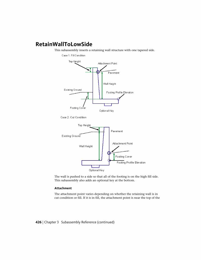
RetainWallToLowSideThis subassembly inserts a retaining wall structure with one tapered side.
The wall is pushed to a side so that all of the footing is on the high fill side.This subassembly also adds an optional key at the bottom.
Attachment
The attachment point varies depending on whether the retaining wall is incut condition or fill. If it is in fill, the attachment point is near the top of the
426 | Chapter 3 Subassembly Reference (continued)

retaining wall. The attachment point is near the footing if it is inserted in cutcondition.
Input Parameters
Note: All dimensions are in meters or feet unless otherwise noted. All slopesare in run-over-rise form (for example, 4 : 1), unless indicated as a percentslope with a “%” sign.
DefaultTypeDescriptionParameter
RightLeft / RightSpecifes to insert the subassemblyeither on the right or the left side of theattachment point.
Side
0.958 ftNumericSpecifies the width of the wall at thetop
Wall Top Width0.292 m
1.320 ftNumericThe distance between the top-of-thewall and the hook in fill or the newhook in cut.
Top Height0.40 m
1.667 ftNumericThe depth of cover from the top-of-footing to the finish grade line on the
Footing Cover0.50 m
back side of the wall in fill or to thehook when in cut.
YesBooleanSpecies to add an optional key belowthe footing
Key
Wall height is determined from top of the footing to attachment point ofground elevation on the vertical face, whichever is higher. Wall battered slope,width of the footing, optional key dimensions, and the location of the keycenter, are all functions of the wall height.
Target ParametersThis section lists the parameters in this subassembly that can be mapped toone or more target objects, such as a surface, alignment, or profile object in
RetainWallToLowSide | 427
a drawing. For more information, see Setting Targets in the AutoCAD Civil3D User’s Guide Help.
StatusDescriptionParameter
OptionalMay be used to override the fixed wall height and tieto a profile. The following object types can be used as
Wall Height
targets for specifying this elevation: profiles, 3D poly-lines, feature lines, or survey figures.
RequiredExisting ground surface name to determine retainingwall in cut or fill. The following object types can be usedas targets for specifying this surfaces: surfaces.
Target Surface
Output Parameters
None.
Behavior
This subassembly can be inserted on either left or right sides. The attachmentpoint is different for the fill or cut condition. In fill, the attachment point isassumed to be where the finish grade intersects the inside face of the wall,below the top of the wall, at a distance equal to the Top Height parameter. Incut, the attachment point is assumed to be where the finish grade intersectsthe inside face, above the top-of-footing, at a distance equal to the FootingCover parameter. The wall height is determined from the Wall Height orProfile input. In fill, the sloping wall face is toward the center of the roadway.In cut, the sloping wall face is away from the roadway, towards the earth beingretained. If the Key option is set to No, then the base of the footing is a singlehorizontal link. If the Key option is used, links to define the optional key areinserted.
Layout Mode Operation
In layout mode, the subassembly draws the retaining wall shape as specifiedby the input parameter values, assuming that the subassembly is in a fillcondition.
428 | Chapter 3 Subassembly Reference (continued)

Point, Link, and Shape CodesThe following table lists the point, link, and shape codes for this subassemblythat have codes assigned to them. Point, link, or shape codes for thissubassembly that do not have codes assigned are not included in this table.
DescriptionCodesPoint/Link
RW_FrontP1
RW_TopP2
RW_BackP3
RW_HingeP14
Could be used as breaklines in buildingdatum surface
RW_InsideP12
Could be used as breaklines in buildingdatum surface
RW_OutsideP5
L1=P1 to P2; L2= P2 to P3; L3 = P3 to P14;Top, WallL1, L2, L3
L4 = P6 to P7; L5 = P8 to P9; L6 = 10 to 11;Footing_BottomL4,L5,L6
RWallS1
Coding Diagram
Fill Condition
RetainWallToLowSide | 429

Cut Condition
RetainWallVerticalThis subassembly inserts a retaining wall structure with both sides as verticalwalls (no tapered side), and an optional key at the bottom.
430 | Chapter 3 Subassembly Reference (continued)
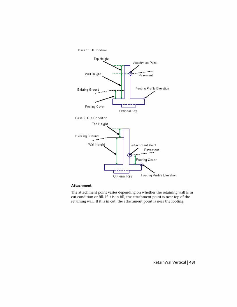
Attachment
The attachment point varies depending on whether the retaining wall is incut condition or fill. If it is in fill, the attachment point is near top of theretaining wall. If it is in cut, the attachment point is near the footing.
RetainWallVertical | 431

Input Parameters
Note: All dimensions are in meters or feet unless otherwise noted. All slopesare in run-over-rise form (for example, 4 : 1), unless indicated as a percentslope with a “%” sign.
DefaultTypeDescriptionParameter
RightLeft / RightSpecifes to insert the sub-assembly either on the right or
Side
the left side of the attachmentpoint.
0.958 ftNumericSpecifies the width of the wall.Wall Width0.292 m
1.320 ftNumericthe distance between the top-of-the wall and the hook in fillor the new hook in cut.
Top Height0.40 m
1.667 ftNumericThe depth of cover from thetop-of-footing to the finish
Footing Cover0.50 m
grade line on the back side ofthe wall in fill or to the hookwhen in cut.
YesBooleanSpecies to add an optional keybelow the footing
Key
Wall height is determined from top of the footing to attachment point ofground elevation on the vertical face, whichever is higher. Width of thefooting, offset of wall vertical face, optional key dimensions, and the locationof the key center, are all functions of the wall height.
Target ParametersThis section lists the parameters in this subassembly that can be mapped toone or more target objects, such as a surface, alignment, or profile object ina drawing. For more information, see Setting Targets in the AutoCAD Civil3D User’s Guide Help.
StatusDescriptionParameter
OptionalMay be used to override the fixed wall height and tieto a profile. The following object types can be used
Wall Height
432 | Chapter 3 Subassembly Reference (continued)

StatusDescriptionParameter
as targets for specifying this elevation: profiles, 3Dpolylines, feature lines, or survey figures.
RequiredExisting ground surface name to determine retainingwall in cut or fill. The following object types can beused as targets for specifying this surfaces: surfaces.
Target Surface
Output Parameters
None.
Behavior
This subassembly can be inserted on either the left or the right sides. Theattachment point is different for the fill or cut condition. In fill, the attachmentpoint is assumed to be where the finish grade intersects the inside face of thewall, below the top of the wall, at a distance equal to the Top Height parameter.In cut, the attachment point is assumed to be where the finish grade intersectsthe inside face, above the top-of-footing at a distance equal to the FootingCover parameter. The wall height is determined from the Wall Height orProfile input.
In fill, the sloping wall face is toward the center of the roadway. In cut, thesloping wall face is away from the roadway, towards the earth being retained.If the Key option is set to No, then the base of the footing is a single horizontallink. If the Key option is used, links to define the optional key are inserted.
Layout Mode Operation
In layout mode, the subassembly draws the retaining wall shape as specifiedby the input parameter values, assuming that the subassembly is in a fillcondition.
Point, Link, and Shape CodesThe following table lists the point, link, and shape codes for this subassemblythat have codes assigned to them. Point, link, or shape codes for thissubassembly that do not have codes assigned are not included in this table.
DescriptionCodesPoint/Link
RW_FrontP1
RW_TopP2
RetainWallVertical | 433

DescriptionCodesPoint/Link
RW_BackP3
RW_HingeP14
Could be used as breaklines in building datum surfaceRW_InsideP12
Could be used as breaklines in building datum surfaceRW_OutsideP5
L1=P1 to P2; L2= P2 to P3; L3 = P3 to P14;TopL1, L2, L3
L4 = P6 to P7; L5 = P8 to P9; L6 = 10 to 11;Footing_BottomL4,L5,L6
RWallS1
Coding Diagram
Fill Condition
Cut Condition
434 | Chapter 3 Subassembly Reference (continued)

ShapeTrapezoidalThis subassembly inserts a trapezoidal shape with flexible parameters andcodes.
This shape can be used as a lane or a shoulder using superelevation parametersfor the slope. The width and outside edge elevation can be calculated basedon an optional alignment and profile. If multiple shapes are stacked, thebottom slope can be used as the top slope of subsequent shapes. If shapes arebutted together, the outside depth can be used as the inside depth of the nextsubassembly. The point, link, and shape codes are left undefined so the shapecan be used to represent different materials in various scenarios.
Attachment
The attachment point is at the inside edge of the shape.
ShapeTrapezoidal | 435
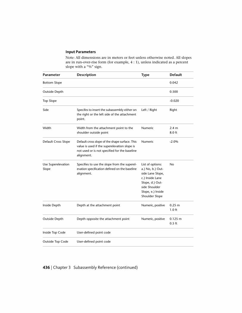
Input ParametersNote: All dimensions are in meters or feet unless otherwise noted. All slopesare in run-over-rise form (for example, 4 : 1), unless indicated as a percentslope with a “%” sign.
DefaultTypeDescriptionParameter
0.042Bottom Slope
0.500Outside Depth
-0.020Top Slope
RightLeft / RightSpecifes to insert the subassembly either onthe right or the left side of the attachmentpoint.
Side
2.4 mNumericWidth from the attachment point to theshoulder outside point
Width8.0 ft
-2.0%NumericDefault cross slope of the shape surface. Thisvalue is used if the superelevation slope is
Default Cross Slope
not used or is not specified for the baselinealignment.
NoList of options:a.) No, b.) Out-
Specifies to use the slope from the superel-evation specification defined on the baselinealignment.
Use SuperelevationSlope
side Lane Slope,c.) Inside LaneSlope, d.) Out-side ShoulderSlope, e.) InsideShoulder Slope
0.25 mNumeric, positiveDepth at the attachment pointInside Depth1.0 ft
0.125 mNumeric, positiveDepth opposite the attachment pointOutside Depth0.5 ft
User-defined point codeInside Top Code
User-defined point codeOutside Top Code
436 | Chapter 3 Subassembly Reference (continued)

DefaultTypeDescriptionParameter
User-defined point codeInside Bottom Code
User-defined point codeOutside Bottom Code
User-defined link codeTop Link Code
User-defined link codeBottom Link Code
User-defined shape codeShape Code
Target ParametersThis section lists the parameters in this subassembly that can be mapped toone or more target objects, such as a surface, alignment, or profile object ina drawing. For more information, see Setting Targets in the AutoCAD Civil3D User’s Guide Help.
StatusType of AssignmentParameter
OptionalMay be used to override the fixed Width and tie the edge-of-shape to an offset aligning. The following object types
Width
can be used as targets for specifying this offset: align-ments, polylines, features lines, or survey figures.
OptionalMay be used to override the normal shape slope and tiethe top outside shape edge to the elevation of a profile.
Outside Elevation
The following object types can be used as targets forspecifying this elevation: profiles, 3D polylines, featurelines, or survey figures.
Output Parameters
TypeDescriptionParameter
NumericSlope of the top linkTop Slope
NumericSlope of the bottom linkBottom Slope
NumericWidth of the shapeWidth
NumericOutside depth of the shapeOutside Depth
ShapeTrapezoidal | 437

Behavior
The finish grade of the shape is inserted for the given Width and % Slopeoutward from the attachment point. The bottom link slope is calculated basedon the inside and outside depth of the shape. The point, link, and shape codesare set in the input parameters using the user-defined strings.
Layout Mode Operation
In layout mode, this subassembly displays the links comprising the shape fora normal crown roadway situation, with default cross slope as the top linkslope value.
Point, Link, and Shape CodesThe following table lists the point, link, and shape codes for this subassemblythat have codes assigned to them. Point, link, or shape codes for thissubassembly that do not have codes assigned are not included in this table.
DescriptionCodeType
User-defined point codeInside Top CodeP1
User-defined point codeOutside Top CodeP2
User-defined point codeInside Bottom CodeP3
User-defined point codeOutside Bottom CodeP4
User-defined link codeTop Link CodeL1
User-defined link codeBottom Link CodeL4
User-defined shape codeShape CodeS1
438 | Chapter 3 Subassembly Reference (continued)

Coding Diagram
ShoulderExtendAllThis subassembly inserts a paved shoulder with all pavement, base, and subbaselayers extended to the shoulder daylight slope.
Attachment
The attachment point is at the inside edge of the paved shoulder, which istypically at the outside edge-of-traveled way.
ShoulderExtendAll | 439
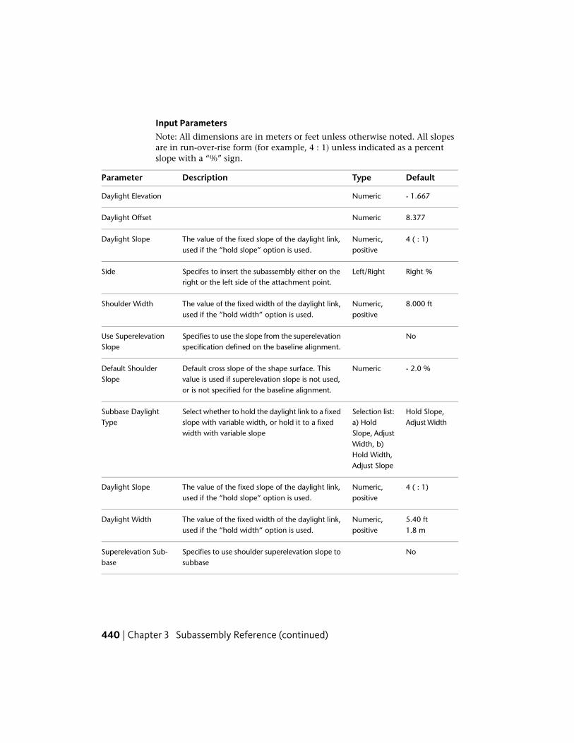
Input ParametersNote: All dimensions are in meters or feet unless otherwise noted. All slopesare in run-over-rise form (for example, 4 : 1) unless indicated as a percentslope with a “%” sign.
DefaultTypeDescriptionParameter
- 1.667NumericDaylight Elevation
8.377NumericDaylight Offset
4 ( : 1)Numeric,positive
The value of the fixed slope of the daylight link,used if the “hold slope” option is used.
Daylight Slope
Right %Left/RightSpecifes to insert the subassembly either on theright or the left side of the attachment point.
Side
8.000 ftNumeric,positive
The value of the fixed width of the daylight link,used if the “hold width” option is used.
Shoulder Width
NoSpecifies to use the slope from the superelevationspecification defined on the baseline alignment.
Use SuperelevationSlope
- 2.0 %NumericDefault cross slope of the shape surface. Thisvalue is used if superelevation slope is not used,or is not specified for the baseline alignment.
Default ShoulderSlope
Hold Slope,Adjust Width
Selection list:a) Hold
Select whether to hold the daylight link to a fixedslope with variable width, or hold it to a fixedwidth with variable slope
Subbase DaylightType
Slope, AdjustWidth, b)Hold Width,Adjust Slope
4 ( : 1)Numeric,positive
The value of the fixed slope of the daylight link,used if the “hold slope” option is used.
Daylight Slope
5.40 ftNumeric,positive
The value of the fixed width of the daylight link,used if the “hold width” option is used.
Daylight Width1.8 m
NoSpecifies to use shoulder superelevation slope tosubbase
Superelevation Sub-base
440 | Chapter 3 Subassembly Reference (continued)
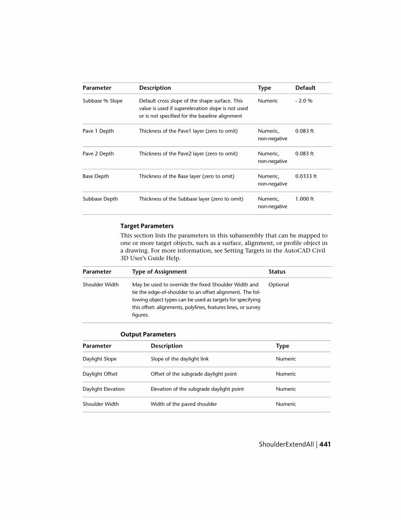
DefaultTypeDescriptionParameter
- 2.0 %NumericDefault cross slope of the shape surface. Thisvalue is used if superelevation slope is not usedor is not specified for the baseline alignment
Subbase % Slope
0.083 ftNumeric,non-negative
Thickness of the Pave1 layer (zero to omit)Pave 1 Depth
0.083 ftNumeric,non-negative
Thickness of the Pave2 layer (zero to omit)Pave 2 Depth
0.0333 ftNumeric,non-negative
Thickness of the Base layer (zero to omit)Base Depth
1.000 ftNumeric,non-negative
Thickness of the Subbase layer (zero to omit)Subbase Depth
Target ParametersThis section lists the parameters in this subassembly that can be mapped toone or more target objects, such as a surface, alignment, or profile object ina drawing. For more information, see Setting Targets in the AutoCAD Civil3D User’s Guide Help.
StatusType of AssignmentParameter
OptionalMay be used to override the fixed Shoulder Width andtie the edge-of-shoulder to an offset alignment. The fol-
Shoulder Width
lowing object types can be used as targets for specifyingthis offset: alignments, polylines, features lines, or surveyfigures.
Output Parameters
TypeDescriptionParameter
NumericSlope of the daylight linkDaylight Slope
NumericOffset of the subgrade daylight pointDaylight Offset
NumericElevation of the subgrade daylight pointDaylight Elevation
NumericWidth of the paved shoulderShoulder Width
ShoulderExtendAll | 441
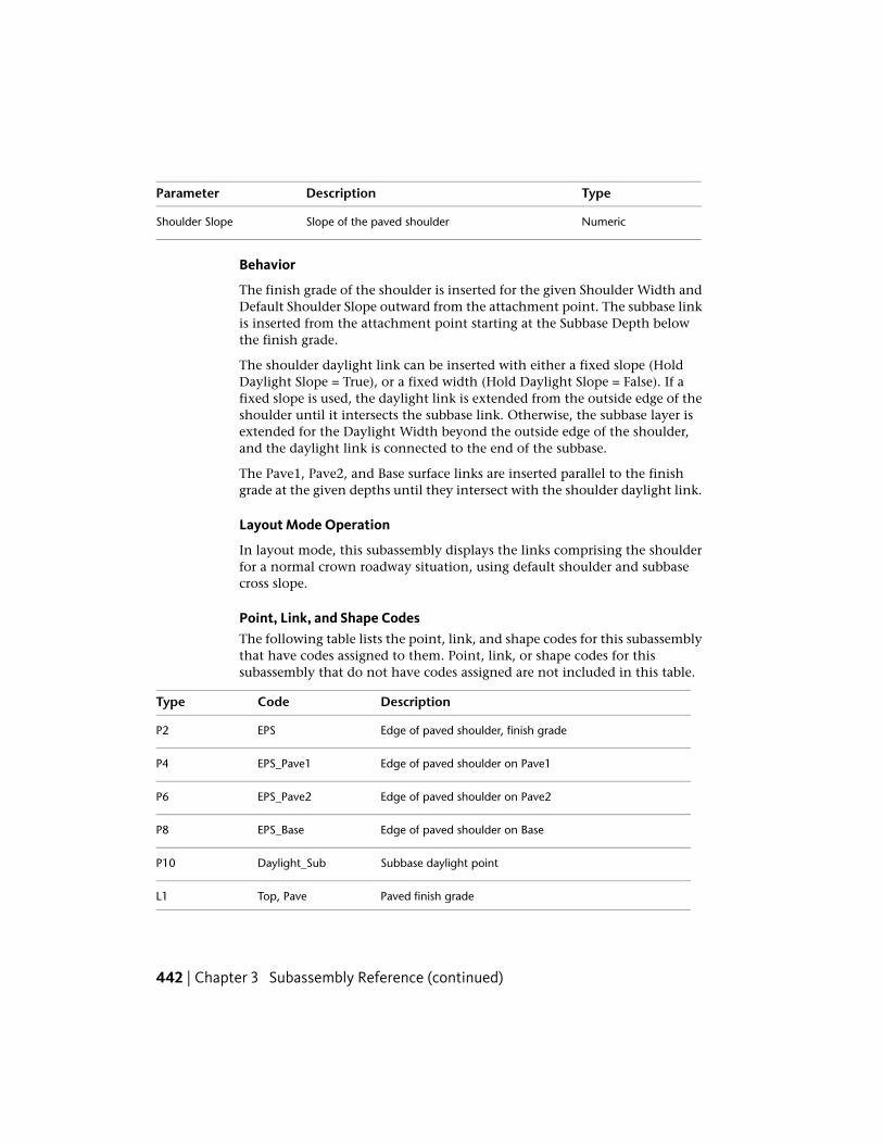
TypeDescriptionParameter
NumericSlope of the paved shoulderShoulder Slope
Behavior
The finish grade of the shoulder is inserted for the given Shoulder Width andDefault Shoulder Slope outward from the attachment point. The subbase linkis inserted from the attachment point starting at the Subbase Depth belowthe finish grade.
The shoulder daylight link can be inserted with either a fixed slope (HoldDaylight Slope = True), or a fixed width (Hold Daylight Slope = False). If afixed slope is used, the daylight link is extended from the outside edge of theshoulder until it intersects the subbase link. Otherwise, the subbase layer isextended for the Daylight Width beyond the outside edge of the shoulder,and the daylight link is connected to the end of the subbase.
The Pave1, Pave2, and Base surface links are inserted parallel to the finishgrade at the given depths until they intersect with the shoulder daylight link.
Layout Mode Operation
In layout mode, this subassembly displays the links comprising the shoulderfor a normal crown roadway situation, using default shoulder and subbasecross slope.
Point, Link, and Shape CodesThe following table lists the point, link, and shape codes for this subassemblythat have codes assigned to them. Point, link, or shape codes for thissubassembly that do not have codes assigned are not included in this table.
DescriptionCodeType
Edge of paved shoulder, finish gradeEPSP2
Edge of paved shoulder on Pave1EPS_Pave1P4
Edge of paved shoulder on Pave2EPS_Pave2P6
Edge of paved shoulder on BaseEPS_BaseP8
Subbase daylight pointDaylight_SubP10
Paved finish gradeTop, PaveL1
442 | Chapter 3 Subassembly Reference (continued)

DescriptionCodeType
Paved finish gradePaveL3
Top of Pavement2Pave1L4
Top of Pavement2Pave1L6
Top of Pavement3Pave2L7
Top of Pavement3Pave2L9
Top of the base courseBaseL10
Top of the base courseBaseL12
Bottom of subbase, datumSubbase, DatumL13
Top surface formation. L14 is the link connecting P2-P10or P2-P8 or P2-P6 or P2-P4, depending on which is thelowest link
Slope_LinkL14
Pave1S1
Pave2S2
BaseS3
SubbaseS4
NOTE L14 is the new link connecting P2-P10 or P2-P8 or P2-P6 or P2-P4,depending on which is the lowest link.
ShoulderExtendAll | 443

Coding Diagram
ShoulderExtendSubbaseThis subassembly inserts a paved shoulder with the subbase layer extendedto a daylight point.
444 | Chapter 3 Subassembly Reference (continued)

Attachment
The attachment point is at the inside edge of the paved shoulder, which istypically at the outside edge-of-traveled way.
Input ParametersNote: All dimensions are in meters or feet unless otherwise noted. All slopesare in run-over-rise form (for example, 4 : 1) unless indicated as a percentslope with a “%” sign.
DefaultTypeDescriptionParameter
- 2.452NumericDaylight Elevation
15.889NumericDaylight Offset
4 ( : 1)Numeric,positive
The value of the fixed slope of the daylight link, usedif the “hold slope” option is used.
Daylight Slope
RightLeft/RightSpecifes to insert the subassembly either on the rightor the left side of the attachment point.
Side
2.4 mNumericWidth from the attachment point to the shoulderhinge point
Shoulder Width8.0 ft
ShoulderExtendSubbase | 445

DefaultTypeDescriptionParameter
OutsideShoulderSlope
SelectionList: a) Out-side
Specifies to use the slope from the superelevationspecification defined on the baseline alignment.
Use SuperelevationSlope
shoulderslope, b)Insideshoulderslope, c)No
-6.000%Numeric,Grade
Default slope of the shoulder if a superelevationslope is not specified.
Default ShoulderSlope
HoldSlope, Ad-just Width
Selectionlist: a)Hold
Select whether to hold the daylight link to a fixedslope with variable width, or hold it to a fixed widthwith variable slope
Subbase DaylightType
Slope, Ad-justWidth, b)HoldWidth, Ad-just Slope
4 ( : 1)Numeric,positive
The value of the fixed slope (x : 1) or fixed width ofthe daylight link, used if the “hold slope” or the“hold width” option is used.
Daylight Slope /Width
OutsideShoulderSlope
SelectionList: a)Outside
Specifies to use superelevation slope for the subbaseslope.
Subbase - Use Super-elevation
shoulderslope, b)Insideshoulderslope, c)No
-6.000%Numeric,Grade
Default slope of the subbase if a superelevation slopeis not specified.
Default SubbaseSlope
446 | Chapter 3 Subassembly Reference (continued)

DefaultTypeDescriptionParameter
0.0Numeric,positive
Width that the Pave1 layer extends beyond theshoulder hinge point. The bottom of the Pave1 layermay not extend beyond the shoulder sideslope.
Pave1 Extension
0.0Numeric,positive
Width that the Pave2 layer extends beyond theshoulder hinge point. This should be equal to or
Pave2 Extension
greater than the Pave1 Extension.The Pave2 layermay not extend beyond the shoulder sideslope.
0.0Numeric,positive
Width that the Base layer extends beyond theshoulder hinge point. This should be equal to or
Base Extension
greater than the Pave2 Extension. The Base layermay not extend beyond the shoulder sideslope.
0.025 mNumeric,non-negat-ive
Depth between finish grade and Pave1 (zero toomit)
Pave1 Depth0.083 ft
0.025 mNumeric,non-negat-ive
Depth between Pave1 and Pave2 (zero to omit)Pave2 Depth0.083 ft
0.100 mNumeric,non-negat-ive
Depth between Pave2 and Base (zero to omit)Base Depth0.333 ft
0.300 mNumeric,non-negat-ive
Depth of the subbase layer at the attachment point(zero to omit)
Subbase Depth1.000 ft
Target ParametersThis section lists the parameters in this subassembly that can be mapped toone or more target objects, such as a surface, alignment, or profile object ina drawing. For more information, see Setting Targets in the AutoCAD Civil3D User’s Guide Help.
StatusType of AssignmentParameter
OptionalMay be used to override the fixed Shoulder Width and tiethe edge-of-shoulder to an offset alignment. The following
Shoulder Width
ShoulderExtendSubbase | 447

StatusType of AssignmentParameter
object types can be used as targets for specifying this offset:alignments, polylines, features lines, or survey figures.
Output Parameters
TypeDescriptionParameter
NumericSlope of the daylight linkDaylight Slope
NumericOffset of the subgrade daylight pointDaylight Offset
NumericElevation of the subgrade daylight pointDaylight Elevation
NumericWidth of the paved shoulderShoulder Width
NumericSlope of the paved shoulderShoulder Slope
Behavior
The finish grade of the shoulder is inserted for the given Shoulder Width andShoulder % Slope outward from the attachment point, and the subbase linkis inserted from the attachment point offset starting at the Subbase Depthbelow the finish grade.
The shoulder daylight link can be inserted with either a fixed slope (HoldDaylight Slope = True) or a fixed width (Hold Daylight Slope = False). If a fixedslope is used, the daylight link is extended from the outside edge of shoulderuntil it intersects the subbase link. Otherwise the subbase layer is extendedfor the Daylight Width beyond the outside edge of shoulder, and the daylightlink is connected to the end of the subbase.
The Pave1, Pave2, and Base surface links are inserted parallel to the finishgrade at the given depths. If the layer Extension values are non-zero, eachlayer is extended for the given distance beyond the shoulder hinge point. Ifa layer extends past the daylight slope, the layer is terminated at the daylightslope intersection. Each layer should be as wide or wider than the one aboveit.
Layout Mode Operation
In layout mode, this subassembly displays the links comprising the shoulderfor a normal crown roadway situation. If numeric slope values are given for
448 | Chapter 3 Subassembly Reference (continued)

the Shoulder % Slope and Subbase % Slope, the links are shown at the givenslope values. Otherwise the default slopes of -6% are used.
Point, Link, and Shape CodesThe following table lists the point, link, and shape codes for this subassemblythat have codes assigned to them. Point, link, or shape codes for thissubassembly that do not have codes assigned are not included in this table.
DescriptionCodeType
Edge of paved shoulder, finish gradeEPSP2
Edge of paved shoulder on Pave1EPS Pave1P4
Edge of paved shoulder on Pave2EPS Pave2P13
Edge of paved shoulder on BaseEPS BaseP7
Subbase daylight pointDaylight SubP11
Paved finish gradeTop, PaveL1, L2
Pave1L4
Pave2L8
BaseL12
SubbaseL15Datum
Unpaved finish gradeTop, GravelL14
Unpaved finish gradeAs shown belowOther Links
Pave1S1
Pave2S2
BaseS3
SubbaseS4
ShoulderExtendSubbase | 449

Coding Diagram
ShoulderMultiLayerThis subassembly inserts a shoulder that you can use to control superelevation.It also supports Pave 2 and Pave 3 Layer extension, as well as varying gradeon Datum.
450 | Chapter 3 Subassembly Reference (continued)

Attachment
The attachment point is at the inside edge of the paved shoulder, which istypically at the outside edge-of-traveled way.
Input ParametersNote: All dimensions are in meters or feet unless otherwise noted. All slopesare in run-over-rise form (for example, 4 : 1) unless indicated as a percentslope with a “%” sign.
DefaultTypeDescriptionParameter
RightLeft / RightSpecifes to insert the sub-assembly either on the right or
Side
the left side of the attachmentpoint.
2.4 mNumericWidth from the attachmentpoint to the shoulder hingepoint
Shoulder Width8.0 ft
0.05 mNumericSpecifies how far the pave 2layer extends from the attach-ment point
Extension Pave 2
0.10 mNumericSpecifies how far the pave 3lay-er extends from the attachmentpoint
Extension Pave 3
Outside Shoulder SlopeSelection list: a)Outside shoulder
Specifies to use the slope fromthe superelevation specification
Use SuperelevationSlope
slope, b) Insidedefined on the baseline align-ment. shoulder slope, c)
No
-2.500%Numeric, GradeDefault slope of the shoulder ifa superelevation slope is notspecified.
Default ShoulderSlope
Hold Slope, AdjustWidth
Selection list: a)Hold Slope, Adjust
Select whether to hold the day-light link to a fixed slope with
Subbase DaylightType
Width, b) HoldWidth, Adjust Slope
variable width, or hold it to afixed width with variable slope
ShoulderMultiLayer | 451

DefaultTypeDescriptionParameter
4 ( : 1)Numeric, positiveThe value of the fixed slope ofthe daylight link, used if oldslope option is used
Daylight Slope
3mNumeric, positiveThe value of the fixed width ofthe daylight link, used if oldwidth option is used
Daylight Width10 ft
0Numeric, positiveWidth of Pave 1 extensionPave 1 Width
0Numeric, positiveWidth of Pave 2 extensionPave 2 Width
0.025 mNumeric, non-neg-ative
Pave depth (zero to omit)Pave Depth0.083 ft
0.025 mNumeric, non-neg-ative
Thickness of the Pave1 layer(zero to omit)
Pave1 Depth0.083 ft
0.025 mNumeric, non-neg-ative
Thickness of the Pave2 layer(zero to omit)
Pave2 Depth0.083 ft
0.025 mNumeric, non-neg-ative
Thickness of the Pave3 layer(zero to omit)
Pave 3 Depth0.083 ft
0.100 mNumeric, non-neg-ative
Thickness of the Base1 layer(zero to omit)
Base1 Depth0.333 ft
0.100 mNumeric, non-neg-ative
Thickness of the Base2 layer(zero to omit)
Base2 Depth0.333 ft
0.100 mNumeric, non-neg-ative
Thickness of the Base3 layer(zero to omit)
Base3 Depth0.333 ft
0.300 mNumeric, non-neg-ative
Thickness of the Subbase1 layer(zero to omit)
Subbase1 Depth1.0 ft
0.300 mNumeric, non-neg-ative
Thickness of the Subbase2 layer(zero to omit)
Subbase2 Depth1.0 ft
452 | Chapter 3 Subassembly Reference (continued)

DefaultTypeDescriptionParameter
0.300 mNumeric, non-neg-ative
Thickness of the Subbase3 layerat the attachment point (zeroto omit)
Subbase3 InnerDepth 1.0 ft
0.300 mNumeric, non-neg-ative
Thickness of the Subbase3 layerat the edge of travelway (zeroto omit)
Subbase3 OuterDepth 1.0 ft
Target ParametersThis section lists the parameters in this subassembly that can be mapped toone or more target objects, such as a surface, alignment, or profile object ina drawing. For more information, see Setting Targets in the AutoCAD Civil3D User’s Guide Help.
StatusTypeParameter
OptionalMay be used to override the fixed ShoulderWidth and tie the edge-of-shoulder to an offset
Shoulder Width
alignment. The following object types can beused as targets for specifying this: alignments,polylines, feature lines, or survey figures.
Output Parameters
TypeDescriptionParameter
NumericSlope of the daylight linkDaylight Slope
NumericOffset of the subgrade daylight pointDaylight Offset
NumericElevation of the subgrade daylight pointDaylight Elevation
NumericWidth of the paved shoulderShoulder Width
NumericSlope of the paved shoulderShoulder Slope
Behavior
This subassembly is inserted on the side of the attachment point specified.All links follow the slope specified for the top link L1, with the exception of
ShoulderMultiLayer | 453

L10. Link L10 is determined by the Subbase 3 Inner Depth and SuperElevation/Grade on Link L1, if a User specified Grade is not given for L10.
Layout Mode Operation
In layout mode, this subassembly displays the links comprising the shoulderfor a normal crowned roadway situation. If numeric slope values are given forthe Shoulder % Slope and Subbase % Slope, the links are shown at the givenslope values. Otherwise the default slopes of -2.50% are used.
Point, Link, and Shape CodesThe following table lists the point, link, and shape codes for this subassemblythat have codes assigned to them. Point, link, or shape codes for thissubassembly that do not have codes assigned are not included in this table.
DescriptionCodesPoint, Link,or Shape
Edg- of-traveledway on top surfaceETWP1
HingeP2
Edge of Pave shoulder on Pave2EPS_Pave2P11
Edge of Pave shoulder on Pave3EPS_Pave3P13
Edge of Paved shoulder on Base1EPS_Base1P3
Edge of Paved shoulder on Base2EPS_Base2P4
Edge of Paved shoulder on Base3EPS_Base3P5
Edge of Paved shoulder on SubBase1EPS_SubBase1P6
Edge of Paved shoulder on SubBase2EPS_SubBase2P7
Edge of Paved shoulder on SubBase3EPS_SubBase3P8
Subbase daylight pointDaylight_SubP9
Finished grade surfaceTop, SRL1
Pave2L2
454 | Chapter 3 Subassembly Reference (continued)
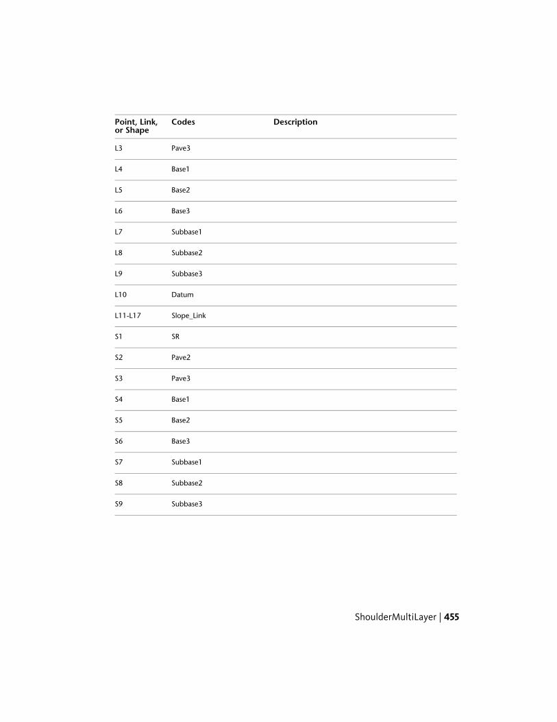
DescriptionCodesPoint, Link,or Shape
Pave3L3
Base1L4
Base2L5
Base3L6
Subbase1L7
Subbase2L8
Subbase3L9
DatumL10
Slope_LinkL11-L17
SRS1
Pave2S2
Pave3S3
Base1S4
Base2S5
Base3S6
Subbase1S7
Subbase2S8
Subbase3S9
ShoulderMultiLayer | 455

Coding Diagram
ShoulderMultiLayerVaryingWidthThis subassembly inserts a shoulder that you can use to control superelevation.It is intended to work in combination with the LaneInsideSuperMultiLayersubassembly and supports Pave 1 through Pave 10 layer extension.
Attachment
The attachment point is at the inside edge of the paved shoulder, which istypically at the outside edge-of-traveled way.
Input ParametersNote: All dimensions are in meters or feet unless otherwise noted. All slopesare in run-over-rise form (for example, 4 : 1) unless indicated as a percentslope with a “%” sign.
DefaultTypeDescriptionParameter
RightLeft / RightSpecifes to insert the sub-assembly either on the right or
Side
the left side of the attachmentpoint.
2.4 mNumericWidth from the attachmentpoint to the shoulder hingepoint
Shoulder Width8.0 ft
456 | Chapter 3 Subassembly Reference (continued)

DefaultTypeDescriptionParameter
Outside Shoulder SlopeSelection list: a)Outside shoulder
Specifies to use the slope fromthe superelevation specification
Use SuperelevationSlope
slope, b) Insidedefined on the baseline align-ment for the shoulder. shoulder slope, c)
No
-6.000%Numeric, GradeDefault slope of the shoulder ifa superelevation slope is notspecified.
Default ShoulderSlope
Hold Slope, AdjustWidth
Selection list: a)Hold Slope, Adjust
Select whether to hold the day-light link to a fixed slope with
Subbase DaylightType
Width, b) HoldWidth, Adjust Slope
variable width, or hold it to afixed width with variable slope
4 ( : 1)Numeric, positiveThe value of the fixed slope (x: 1) of the daylight link
Daylight Slope
3mNumeric, positiveValue of the fixed widthWidth10 ft
0Numeric, positiveWidth of Pave 1 extensionPave 1 Width
0Numeric, positiveWidth of Pave 2 extensionPave 2 Width
0.025 mNumeric, non-neg-ative
Pave depth (zero to omit)Pave Depth0.083 ft
0.025 mNumeric, non-neg-ative
Thickness of the Pave1 layer(zero to omit)
Pave1 Depth0.083 ft
0.025 mNumeric, non-neg-ative
Thickness of the Pave2 layer(zero to omit)
Pave2 Depth0.083 ft
0.025 mNumeric, non-neg-ative
Thickness of the Pave3 layer(zero to omit)
Pave 3 Depth0.083 ft
0.100 mNumeric, non-neg-ative
Thickness of the Base1 layer(zero to omit)
Base1 Depth0.333 ft
ShoulderMultiLayerVaryingWidth | 457

DefaultTypeDescriptionParameter
0.100 mNumeric, non-neg-ative
Thickness of the Base2 layer(zero to omit)
Base2 Depth0.333 ft
0.100 mNumeric, non-neg-ative
Thickness of the Base3 laye(zero to omit)r
Base3 Depth0.333 ft
0.300 mNumeric, non-neg-ative
Thickness of the Subbase1 layer(zero to omit)
Subbase1 Depth1.0 ft
0.300 mNumeric, non-neg-ative
Thickness of the Subbase2 layer(zero to omit)
Subbase2 Depth1.0 ft
0.300 mNumeric, non-neg-ative
Thickness of the Subbase3 layerat the attachment point (zeroto omit)
Subbase3 InnerDepth 1.0 ft
0.300 mNumeric, non-neg-ative
Thickness of the Subbase3 layerat the edge of travelway (zeroto omit)
Subbase3 OuterDepth 1.0 ft
Target ParametersThis section lists the parameters in this subassembly that can be mapped toone or more target objects, such as a surface, alignment, or profile object ina drawing. For more information, see Setting Targets in the AutoCAD Civil3D User’s Guide Help.
StatusTypeParameter
OptionalAlignment that defines the edge of the pavedportion of the shoulder. May be used to override
Shoulder Width
the fixed Shoulder Width and tie the edge-of-shoulder to an offset alignment. The followingobject types can be used as targets for specifyingthis: alignments, polylines, feature lines, or sur-vey figures.
Output Parameters
TypeDescriptionParameter
NumericSlope of the daylight linkDaylight Slope
458 | Chapter 3 Subassembly Reference (continued)
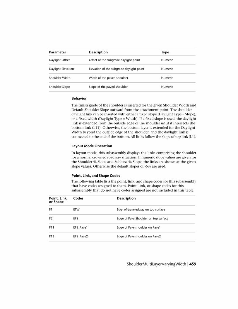
TypeDescriptionParameter
NumericOffset of the subgrade daylight pointDaylight Offset
NumericElevation of the subgrade daylight pointDaylight Elevation
NumericWidth of the paved shoulderShoulder Width
NumericSlope of the paved shoulderShoulder Slope
Behavior
The finish grade of the shoulder is inserted for the given Shoulder Width andDefault Shoulder Slope outward from the attachment point. The shoulderdaylight link can be inserted with either a fixed slope (Daylight Type = Slope),or a fixed width (Daylight Type = Width). If a fixed slope is used, the daylightlink is extended from the outside edge of the shoulder until it intersects thebottom link (L11). Otherwise, the bottom layer is extended for the DaylightWidth beyond the outside edge of the shoulder, and the daylight link isconnected to the end of the bottom. All links follow the slope of top link (L1).
Layout Mode Operation
In layout mode, this subassembly displays the links comprising the shoulderfor a normal crowned roadway situation. If numeric slope values are given forthe Shoulder % Slope and Subbase % Slope, the links are shown at the givenslope values. Otherwise the default slopes of -6% are used.
Point, Link, and Shape CodesThe following table lists the point, link, and shape codes for this subassemblythat have codes assigned to them. Point, link, or shape codes for thissubassembly that do not have codes assigned are not included in this table.
DescriptionCodesPoint, Link,or Shape
Edg- of-traveledway on top surfaceETWP1
Edge of Pave Shoulder on top surfaceEPSP2
Edge of Pave shoulder on Pave1EPS_Pave1P11
Edge of Pave shoulder on Pave2EPS_Pave2P13
ShoulderMultiLayerVaryingWidth | 459

DescriptionCodesPoint, Link,or Shape
Edge of Paved shoulder on Base1EPS_Base1P3
Edge of Paved shoulder on Base2EPS_Base2P4
Edge of Paved shoulder on Base3EPS_Base3P5
Edge of Paved shoulder on SubBase1EPS_SubBase1P6
Edge of Paved shoulder on SubBase2EPS_SubBase2P7
Edge of Paved shoulder on SubBase3EPS_SubBase3P8
Subbase daylight pointDaylight_SubP9
Finish grade surfaceTop, PaveL1
Pave1L2
Pave2L3
Pave3L4
Base1L5
Base2L6
Base3L7
Subbase1L8
Subbase2L9
Datum, Subbase3L10
Slope_LinkL11-L17
PaveS1
Pave1S2
460 | Chapter 3 Subassembly Reference (continued)

DescriptionCodesPoint, Link,or Shape
Pave2S3
Pave3S4
Base1S5
Base2S6
Base3S7
Subbase1S8
Subbase2S9
Subbase3S10
Coding Diagram
ShoulderMultiSurfaceThis subassembly inserts a paved and an earthen (unpaved or gravel) shoulderwith all pavement, base, and subbase layers extended to the subgrade shoulderpoint.
ShoulderMultiSurface | 461
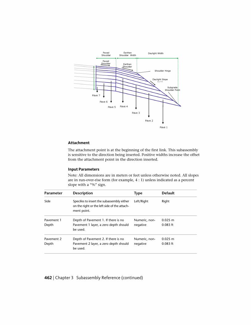
Attachment
The attachment point is at the beginning of the first link. This subassemblyis sensitive to the direction being inserted. Positive widths increase the offsetfrom the attachment point in the direction inserted.
Input ParametersNote: All dimensions are in meters or feet unless otherwise noted. All slopesare in run-over-rise form (for example, 4 : 1) unless indicated as a percentslope with a “%” sign.
DefaultTypeDescriptionParameter
RightLeft/RightSpecifes to insert the subassembly eitheron the right or the left side of the attach-ment point.
Side
0.025 mNumeric, non-negative
Depth of Pavement 1. If there is noPavement 1 layer, a zero depth shouldbe used.
Pavement 1Depth 0.083 ft
0.025 mNumeric, non-negative
Depth of Pavement 2. If there is noPavement 2 layer, a zero depth shouldbe used.
Pavement 2Depth 0.083 ft
462 | Chapter 3 Subassembly Reference (continued)
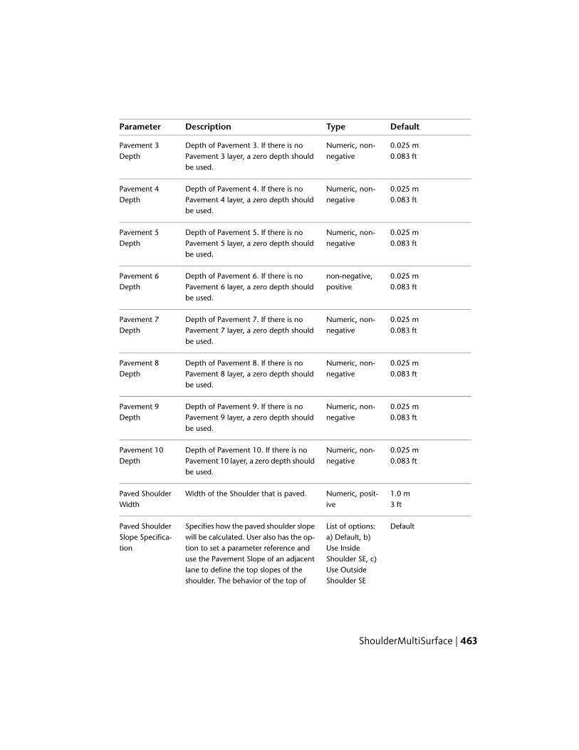
DefaultTypeDescriptionParameter
0.025 mNumeric, non-negative
Depth of Pavement 3. If there is noPavement 3 layer, a zero depth shouldbe used.
Pavement 3Depth 0.083 ft
0.025 mNumeric, non-negative
Depth of Pavement 4. If there is noPavement 4 layer, a zero depth shouldbe used.
Pavement 4Depth 0.083 ft
0.025 mNumeric, non-negative
Depth of Pavement 5. If there is noPavement 5 layer, a zero depth shouldbe used.
Pavement 5Depth 0.083 ft
0.025 mnon-negative,positive
Depth of Pavement 6. If there is noPavement 6 layer, a zero depth shouldbe used.
Pavement 6Depth 0.083 ft
0.025 mNumeric, non-negative
Depth of Pavement 7. If there is noPavement 7 layer, a zero depth shouldbe used.
Pavement 7Depth 0.083 ft
0.025 mNumeric, non-negative
Depth of Pavement 8. If there is noPavement 8 layer, a zero depth shouldbe used.
Pavement 8Depth 0.083 ft
0.025 mNumeric, non-negative
Depth of Pavement 9. If there is noPavement 9 layer, a zero depth shouldbe used.
Pavement 9Depth 0.083 ft
0.025 mNumeric, non-negative
Depth of Pavement 10. If there is noPavement 10 layer, a zero depth shouldbe used.
Pavement 10Depth 0.083 ft
1.0 mNumeric, posit-ive
Width of the Shoulder that is paved.Paved ShoulderWidth 3 ft
DefaultList of options:a) Default, b)
Specifies how the paved shoulder slopewill be calculated. User also has the op-
Paved ShoulderSlope Specifica-tion Use Insidetion to set a parameter reference and
Shoulder SE, c)use the Pavement Slope of an adjacentUse OutsideShoulder SE
lane to define the top slopes of theshoulder. The behavior of the top of
ShoulderMultiSurface | 463

DefaultTypeDescriptionParameter
shoulder slope when this option is selec-ted is described in the Behavior section.
-4.0%SlopeDefault cross slope of the pavedshoulder surface
Default PavedShoulder Slope
Numeric, posit-ive
Width of the Shoulder that is unpavedEarthenedShoulder Width
DefaultList of options:a) Default, b)
Specifies how the unpaved shoulderslope will be calculated. User also has
EarthenedShoulder SlopeSpecification Use Insidethe option to set a parameter reference
Shoulder SE, c)and use the Pavement Slope of an adja-Use OutsideShoulder SE
cent lane to define the top slopes of theshoulder. The behavior of the top ofshoulder slope when this option is selec-ted is described in the Behavior section.
-4.0%SlopeDefault cross slope of the unpavedshoulder surface.
DefaultEarthenedShoulder Slope
1.0 mNumeric, posit-ive
Specifies the shoulder daylight widthDaylight Width3 ft
2: 1SlopeSlope of the Foreslope of the shoulder,which extends from the Shoulder HingePoint to the Subgrade Shoulder Point
Daylight Slope
Hold Slope, AdjustWidth
Selection list: a)Hold Slope, Ad-
Select whether to hold the daylight linkto a fixed slope with variable width, or
Subbase Day-light Type
just Width, b)hold it to a fixed width with variableslope Hold Width, Ad-
just Slope
Target ParametersThis section lists the parameters in this subassembly that can be mapped toone or more target objects, such as a surface, alignment, or profile object in
464 | Chapter 3 Subassembly Reference (continued)

a drawing. For more information, see Setting Targets in the AutoCAD Civil3D User’s Guide Help.
StatusDescriptionParameter
OptionalAlignment that defines the edge of the paved portionof the shoulder. The following object types can be used
Paved ShoulderWidth
as targets for specifying this: alignments, polylines,feature lines, or survey figures.
OptionalAlignment that defines the shoulder hinge point. Thefollowing object types can be used as targets for spe-
Earthened ShoulderWidth
cifying this: alignments, polylines, feature lines, orsurvey figures.
OptionalAlignment that defines the location of the subgradeshoulder point.
Daylight Width
OptionalProfile that defines the elevation of the shoulder sub-grade point. The following object types can be used
Daylight Slope
as targets for specifying this elevation: profiles, 3Dpolylines, feature lines, or survey figures.
Output Parameters
TypeDescriptionParameter
NumericSlope of the daylight linkDaylight Slope
NumericOffset of the subgrade daylight pointDaylight Offset
NumericElevation of the subgrade daylight pointDaylight Elevation
Behavior
The shoulder is inserted using width and depth parameters provided. Theslope of the subgrade surface can also be set using a parameter reference thatsets the slope equal to that of the subgrade surface of an adjacent lane. Youcan also enter a fixed slope, if desired. The slopes of all base surfaces will followthe slope of the subgrade surface. When an alignment is used to define theWidth to Subgrade Shoulder Point, the Foreslope of the Shoulder parameteris ignored. The shoulder subassembly ties in to the pavement layers (even ifthe outside edges of the pavement layers are extended).
ShoulderMultiSurface | 465

Layout Mode Operation
In layout mode, this subassembly displays the links defined by the inputparameters.
Point, Link, and Shape CodesThe following table lists the point, link, and shape codes for this subassemblythat have codes assigned to them. Point, link, or shape codes for thissubassembly that do not have codes assigned are not included in this table.
DescriptionCodesPoint, Link, orShape
Edge-of-traveledway on top surfaceETWP1
Edge of Paved ShoulderEPSP2
No codes are assigned to these points.P3 throughP27
Coding Diagram
466 | Chapter 3 Subassembly Reference (continued)

ShoulderVerticalSubbaseThis subassembly inserts a paved shoulder with the pavement and subbaselayers terminating with a vertical link.
Attachment
The attachment point is at the inside edge of the paved shoulder, which istypically at the outside edge-of-traveled way.
Input ParametersNote: All dimensions are in meters or feet unless otherwise noted. All slopesare in run-over-rise form (for example, 4 : 1) unless indicated as a percentslope with a “%” sign.
DefaultTypeDescriptionParameter
RightLeft/RightSpecifes to insert the subassembly either on theright or the left side of the attachment point.
Side
2.4 mNumericWidth from the attachment point to the edge ofpaved shoulder
Paved Width8.0 ft
-6.000%Numeric,Grade
Default slope of the paved shoulder, if a superelev-ation slope is not specified.
Default Paved Slope
OutsideShoulderSlope
SelectionList: a) Out-side
Specifies to use superelevation slope, from the su-perelevation specification defined on the baselinealignment, for the paved portion of the shoulder.
Use SuperelevationSlope
shoulderslope, b)Insideshoulderslope, c)No
ShoulderVerticalSubbase | 467

DefaultTypeDescriptionParameter
1Numeric,1 – 3
Determines when or if the unpaved portion of theshoulder is inserted. Value should be one of thefollowing:
Unpaved Link Treat-ment
Code: Treatment1: Always used2: Used only if shoulder is in cut3: Used only if shoulder is in cut, or is in fill on thehigh side of superelevation.
1.8 mNumeric,positive
Width of the unpaved portion of the shoulder. Setto zero to omit the unpaved link.
Unpaved Width6.0 ft
-6 (%)Numeric,positive
% slope of the unpaved shoulder surfaceUnpaved % Slope
8 (%)Numeric,positive
Maximum breakover between the % slopes of thepaved and unpaved portions on the high side ofsuperelevation
Unpaved Max Break-over
0.025mNumeric,non-negat-ive
Depth between finish grade and Pave1 (zero toomit)
Pave1 Depth0.083 ft
0.025 mNumeric,non-negat-ive
Depth between Pave1 and Pave2 (zero to omit)Pave2 Depth0.083 ft
0.100 mNumeric,non-negat-ive
Depth between Pave2 and Base (zero to omit)Base Depth0.333 ft
0.300 mNumeric,non-negat-ive
Depth between Base and Subbase (zero to omit)Subbase Depth1.0 ft
Target ParametersThis section lists the parameters in this subassembly that can be mapped toone or more target objects, such as a surface, alignment, or profile object in
468 | Chapter 3 Subassembly Reference (continued)

a drawing. For more information, see Setting Targets in the AutoCAD Civil3D User’s Guide Help.
StatusType of AssignmentParameter
OptionalMay be used to override the fixed Paved Width andtie the edge-of-shoulder to an offset alignment. The
Paved Width
following object types can be used as targets forspecifying this offset: alignments, polylines, featureslines, or survey figures.
Conditional; required if Un-paved Link Treatment is 2 or3.
Used to determine if the outside edge of pavedshoulder is in cut or fill. This parameter is notneeded if the Unpaved Link Treatment is 1. The
Daylight Surface
following object types can be used as targets forspecifying this surfaces: surfaces.
Output Parameters
TypeDescriptionParameter
NumericWidth of the paved shoulderShoulder Width
NumericSlope of the paved shoulderShoulder Slope
Behavior
The links for the shoulder finish grade, Pave1, Pave2, Base and Subbase areinserted outward using the given Paved Width, Paved % Slope, material depths.If the Unpaved Link Treatment is 1, the unpaved shoulder link is insertedunder all conditions. If the Treatment code is 2, the outside edge of the pavedshoulder is checked to determine if it is in cut or fill; the unpaved shoulderlink is inserted only in cut. Treatment code 3 uses the unpaved link in cut, orwhen the paved shoulder link has a positive %slope.The unpaved finish gradelink is inserted at the given Unpaved % Slope, unless the difference betweenthe Paved %Slope and Unpaved %Slope exceeds the Unpaved Max Breakovervalue. In that case the slope of the unpaved link is adjusted to hold thedifference to the given breakover..
Layout Mode Operation
In layout mode, this subassembly displays the links comprising the shoulderfor the normal crown roadway condition, based on the input parametersprovided. If a numeric value is given for the Paved %Slope, the paved portion
ShoulderVerticalSubbase | 469
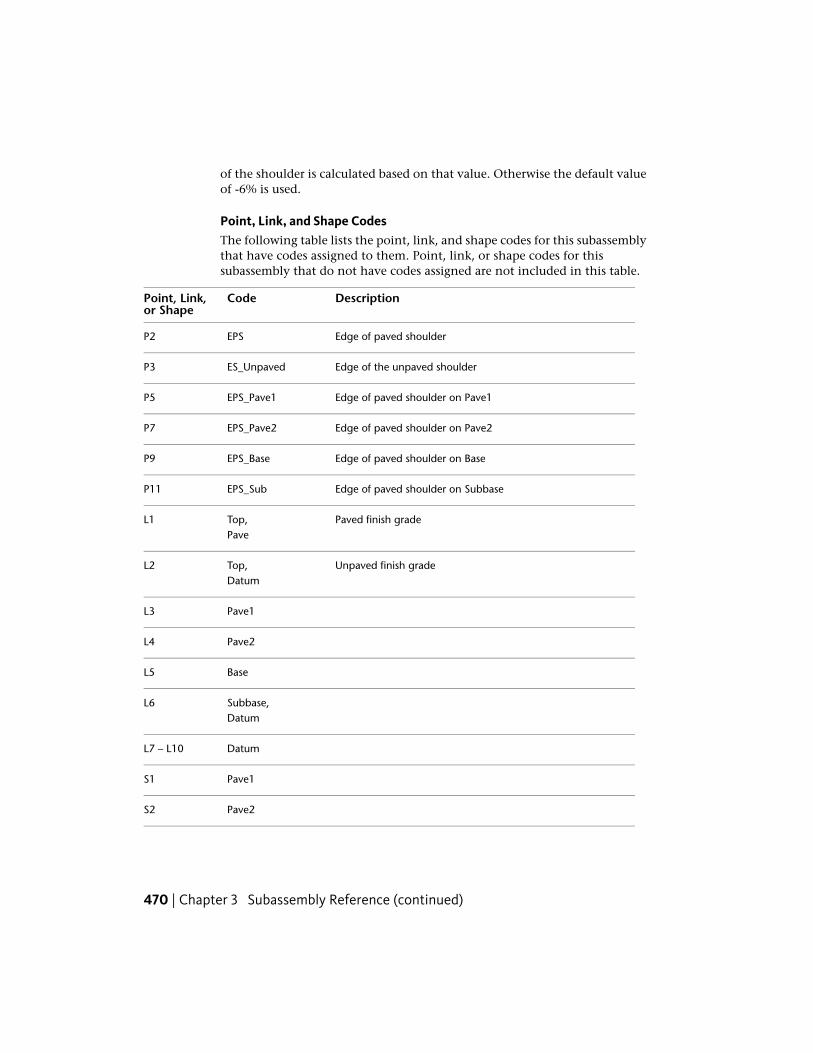
of the shoulder is calculated based on that value. Otherwise the default valueof -6% is used.
Point, Link, and Shape CodesThe following table lists the point, link, and shape codes for this subassemblythat have codes assigned to them. Point, link, or shape codes for thissubassembly that do not have codes assigned are not included in this table.
DescriptionCodePoint, Link,or Shape
Edge of paved shoulderEPSP2
Edge of the unpaved shoulderES_UnpavedP3
Edge of paved shoulder on Pave1EPS_Pave1P5
Edge of paved shoulder on Pave2EPS_Pave2P7
Edge of paved shoulder on BaseEPS_BaseP9
Edge of paved shoulder on SubbaseEPS_SubP11
Paved finish gradeTop,L1Pave
Unpaved finish gradeTop,L2Datum
Pave1L3
Pave2L4
BaseL5
Subbase,L6Datum
DatumL7 – L10
Pave1S1
Pave2S2
470 | Chapter 3 Subassembly Reference (continued)

DescriptionCodePoint, Link,or Shape
BaseS3
SubbaseS4
Coding Diagram
ShoulderWideningThis subassembly inserts a shoulder for widening situations that will trim thebase and subbase layers based on the location of the existing ground surface.
ShoulderWidening | 471

Attachment
The attachment point is at the inside edge of the shoulder on the finish gradesurface.
Input ParametersNote: All dimensions are in meters or feet unless otherwise noted. All slopesare in run-over-rise form (for example, 4 : 1) unless indicated as a percentslope with a “%” sign.
DefaultTypeDescriptionParameter
RightLeft / RightSpecifes to insert the subassembly eitheron the right or the left side of the attach-ment point.
Side
- 2.0 %NumericDefault cross slope of the shape surface.This value is used if superelevation slope
Default Shoulder Slope
is not used, or is not specified for thebaseline alignment.
Hold Slope, Ad-just Width
Selection list: a)Hold Slope, Ad-
Select whether to hold the daylight linkto a fixed slope with variable width, or
Subbase Daylight Type
just Width, b)hold it to a fixed width with variableslope Hold Width, Ad-
just Slope
4 ( : 1)Numeric, posit-ive
The value of the fixed slope of the day-light link, used if the “hold slope” op-tion is used
Daylight Slope
5.40 ftNumeric, posit-ive
The value of the fixed width of thedaylight link, used if the “hold width”option is used
Daylight Width1.8 m
0.025 mNumeric, non-negative
Depth of Pave 1 (zero to omit)Pave 1 Depth0.083 ft
0.025 mNumeric, non-negative
Depth of Pave 2 (zero to omit)Pave 2 Depth0.083 ft
0.100 mNumeric, non-negative
Depth of base layer (zero to omit)Base Depth0.333 ft
472 | Chapter 3 Subassembly Reference (continued)

DefaultTypeDescriptionParameter
0.300 mNumeric, non-negative
Depth of Subbase Layer (zero to omit)Subbase Depth1.0 ft
- 2.0 %NumericDefault cross slope of the shape surface.This value is used if superelevation slope
Default Subbase Slope
is not used, or is not specified for thebaseline alignment.
Target ParametersThis section lists the parameters in this subassembly that can be mapped toone or more target objects, such as a surface, alignment, or profile object ina drawing. For more information, see Setting Targets in the AutoCAD Civil3D User’s Guide Help.
StatusDescriptionParameter
OptionalMay be used to override the fixed Shoulder Widthand tie the edge-of-shoulder to an offset alignment.
Shoulder Width
The following object types can be used as targets forspecifying this: alignments, polylines, feature lines,or survey figures.
OptionalMay be used to specify an existing surface to trimbase and subbase layers to. The following object
Existing Surface
types can be used as targets for specifying this sur-face: surfaces.
Output Parameters
TypeDescriptionParameter
NumericSlope of the daylight linkDaylight Slope
NumericOffset of the subgrade daylight pointDaylight Offset
NumericElevation of the subgrade daylight pointDaylight Elevation
NumericWidth of the paved shoulderShoulder Width
NumericSlope of the paved shoulderShoulder Slope
ShoulderWidening | 473

Behavior
When inserted, this subassembly checks for the presence of the target existingground surface. If this surface exists, then the base and subbase surfaces willbe trimmed to the existing ground.
If the surface does not exist, then this shoulder behaves the same as theShoulderExtendAll subassembly.
Layout Mode Operation
In layout mode, this subassembly displays the links defined by the inputparameters.
Point, Link, and Shape CodesThe following table lists the point, link, and shape codes for this subassemblythat have codes assigned to them. Point, link, or shape codes for thissubassembly that do not have codes assigned are not included in this table.
DescriptionCodePoint, Link, orShape
Edge of paved shoulder, finish gradeEPSP2
Edge of paved shoulder on Pave1EPS_Pave1P4
Edge of paved shoulder on Pave2EPS_Pave2P6
Edge of paved shoulder on BaseEPS_BaseP8
Subbase daylight pointDaylight_SubP10
Paved finish gradeTop, PaveL1
Paved finish gradePaveL3
Top of Pavement2Pave1L4
Top of Pavement2Pave1L6
Top of Pavement3Pave2L7
Top of Pavement3Pave2L9
Top of the base courseBaseL10
474 | Chapter 3 Subassembly Reference (continued)

DescriptionCodePoint, Link, orShape
Top of the base courseBaseL12
Bottom of subbase, datumSubbase, DatumL13
Top surface formationTopL14
Pave1S1
Pave2S2
BaseS3
SubbaseS4
Coding Diagram
ShoulderWidening | 475

ShoulderWithSubbaseInterlacedThis subassembly inserts a paved shoulder with all layers including subbaseextended to a daylight point. Optionally you can reduce the depths of varioussublayers to interlace subbase material around some of the select materiallayers.
Attachment
The attachment point is at the inside edge of the paved shoulder, which istypically at the outside edge-of-traveled way.
476 | Chapter 3 Subassembly Reference (continued)

Input ParametersNote: All dimensions are in meters or feet unless otherwise noted. All slopesare in run-over-rise form (for example, 4 : 1) unless indicated as a percentslope with a “%” sign.
DefaultTypeDescriptionParameter
RightLeft/RightSpecifes to insert the subassembly eitheron the right or the left side of the attach-ment point.
Side
2.4 mNumericWidth from the attachment point to theshoulder hinge point.
Shoulder Width8.0 ft
NoList of options:a.) No, b.) Out-
Specifies to use the slope from the super-elevation specification defined on thebaseline alignment.
Use Supereleva-tion Slope
side shoulderslope, c.) Insideshoulder slope
-4.0%NumericDefault cross slope of the shoulder surface.This value is used if superelevation slope
DefaultShoulder Slope
is not used, or is not specified for thebaseline alignment.
Hold Slope, AdjustWidth
Selection list: a)Hold Slope, Ad-
Select whether to hold the daylight linkto a fixed slope with variable width, orhold it to a fixed width with variable slope
Subbase Day-light Type
just Width, b)Hold Width, Ad-just Slope
4 ( : 1)Numeric, positiveThe value of the fixed width or fixed slope(x : 1) of the daylight link.
Daylight Slope/ Width
NoList of options:a.) No, b.) Out-
Specifies to use the slope from the super-elevation specification defined on thebaseline alignment.
Subbase Super-elevation
side shoulderslope, c.) Insideshoulder slope
-4.0%NumericDefault cross slope of the subbase surface.This value is used if superelevation slope
Default SubbaseSlope
ShoulderWithSubbaseInterlaced | 477

DefaultTypeDescriptionParameter
is not used, or is not specified for thebaseline alignment.
0.025 mNumeric, non-negative
Depth between finish grade and Pave1(zero to omit)
Pave1 Depth(0.083 ft)
0.000mNumeric, positiveDepth reduction of Pave1 to interlacesubbase material between Pave1 andPave2
Gap betweenPave1 and Pave2
0.000 ft
0.025 mNumeric, non-negative
Depth second level pavement material(zero to omit)
Pave2 Depth0.083 ft
0.4 mNumeric, positiveReduced width of Pave 2 material to en-able subbase interlacing. Side edge of the
Pave2 Trim1.32 ft
material layer will have same slope asshoulder daylight slope.
0.01 mNumeric, positiveDepth reduction of pave2 to interlacesubbase material between Pave2 and BaseCourse
Gap betweenPave2 and Base (.033 ft
0.100 mNumeric, non-negative
Depth of base course (between Pave2 andBase; zero to omit)
Base Depth0.333 ft
0.4 mNumeric, positiveReduced width of Base course material toto enable subbase interlacing. Side edge
Base Trim1.32 ft
of the material layer will have same slopeas shoulder daylight slope.
0.300 mNumeric, non-negative
Depth of the subbase layer at the attach-ment point from bottom of base course(zero to omit)
Subbase Depth1.0 ft
0.0Numeric, non-negative
Specifies depth of material lining alongdaylight link. If a value of ZERO is entered- then no lining material is added.
Topsoil Thick-ness
TopsoilStringSpecifies shape code for the topsoil mater-ial
Topsoil ShapeCode
478 | Chapter 3 Subassembly Reference (continued)

DefaultTypeDescriptionParameter
Pave1StringSpecifies shape code for the top layer(below topsoil if enabled) material
Pave1 ShapeCode
Pave2StringSpecifies shape code for the second layermaterial (above base course)
Pave2 ShapeCode
Target ParametersThis section lists the parameters in this subassembly that can be mapped toone or more target objects, such as a surface, alignment, or profile object ina drawing. For more information, see Setting Targets in the AutoCAD Civil3D User’s Guide Help.
StatusDescriptionParameter
OptionalCan be used to override the fixed Shoulder Widthand tie the edge-of-shoulder to an offset alignment.
Shoulder Width
The following object types can be used as targetsfor specifying this offset: alignments, polylines, fea-tures lines, or survey figures.
Output Parameters
TypeDescriptionParameter
NumericSlope of the daylight linkDaylight Slope
NumericOffset of the subgrade daylight pointDaylight Offset
NumericElevation of the subgrade daylight pointDaylight Elevation
NumericWidth of the paved shoulderShoulder Width
NumericSlope of the paved shoulderShoulder Slope
Behavior
The finish grade of the shoulder is inserted for the given Shoulder Width andDefault Shoulder Slope outward from the attachment point. The subbase linkis inserted from the attachment point starting at the Subbase Depth belowthe finish grade.
ShoulderWithSubbaseInterlaced | 479
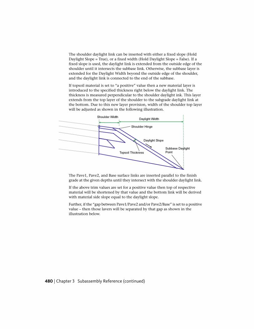
The shoulder daylight link can be inserted with either a fixed slope (HoldDaylight Slope = True), or a fixed width (Hold Daylight Slope = False). If afixed slope is used, the daylight link is extended from the outside edge of theshoulder until it intersects the subbase link. Otherwise, the subbase layer isextended for the Daylight Width beyond the outside edge of the shoulder,and the daylight link is connected to the end of the subbase.
If topsoil material is set to “a positive” value then a new material layer isintroduced to the specified thickness right below the daylight link. Thethickness is measured perpendicular to the shoulder daylight ink. This layerextends from the top layer of the shoulder to the subgrade daylight link atthe bottom. Due to this new layer provision, width of the shoulder top layerwill be adjusted as shown in the following illustration.
The Pave1, Pave2, and Base surface links are inserted parallel to the finishgrade at the given depths until they intersect with the shoulder daylight link.
If the above trim values are set for a positive value then top of respectivematerial will be shortened by that value and the bottom link will be derivedwith material side slope equal to the daylight slope.
Further, if the “gap between Pave1/Pave2 and/or Pave2/Base” is set to a positivevalue – then those lavers will be separated by that gap as shown in theillustration below.
480 | Chapter 3 Subassembly Reference (continued)

If the gaps between Pave1/Pave2 and Pave2/Base are set to ZERO then thesubassembly will be drawn as shown below.
If the sub-layers are set with zero trim values, then this subassembly will besimilar to the ShoulderExtendAll subassembly with optional topsoil lining.
Layout Mode Operation
In layout mode this subassembly displays the links comprising the shoulderwith default parameters assigned to it.
ShoulderWithSubbaseInterlaced | 481

Point, Link, and Shape CodesThe following table lists the point, link, and shape codes for this subassemblythat have codes assigned to them. Point, link, or shape codes for thissubassembly that do not have codes assigned are not included in this table.
DescriptionCodesType
Edge of paved shoulder, finish gradeEPSP2
Subbase daylight pointDaylight_SubP3
Edge of paved shoulder on Pave1EPS_Pave1P5
Edge of paved shoulder on Pave2EPS_Pave2P7
Edge of paved shoulder on BaseEPS_BaseP9
Finish grade of the shoulderTopL1, L2
Pave1L4
Pave2L5
BaseL6
Datum, SubbaseL3
User defined code for top layer of shoulder (default - Pave1)User Defined CodeS1
User defined code for second layer of shoulder (default - Pave2)User Defined CodeS2
BaseS3
SubbaseS4
User defined code for topsoil material (default - Topsoil)User Defined CodeS5
482 | Chapter 3 Subassembly Reference (continued)

Coding Diagram
ShoulderWithSubbaseInterlacedAndDitchThis subassembly inserts a paved shoulder with all pavement, base, and subbaselayers extended to the shoulder daylight slope.
ShoulderWithSubbaseInterlacedAndDitch | 483

Attachment
The attachment point is at the inside edge of the paved shoulder, which istypically at the outside edge-of-traveled way.
Input Parameters
Note: All dimensions are in meters or feet unless otherwise noted. All slopesare in run-over-rise form (for example, 4 : 1) unless indicated as a percentslope with a “%” sign.
DefaultTypeDescriptionParameter
RightLeft / RightSpecifes to insert the subassembly either onthe right or the left side of the attachmentpoint.
Side
2.4 mNumericWidth from the attachment point to theshoulder hinge point.
Shoulder Width8.0 ft
NoList of options:a.) No, b.) Out-
Specifies to use the slope from the superel-evation specification defined on the baselinealignment.
Use Supereleva-tion Slope
side shoulderslope, c.) Insideshoulder slope
-6.0%NumericDefault cross slope of the shoulder surface.This value is used if superelevation slope is
Default ShoulderSlope
484 | Chapter 3 Subassembly Reference (continued)

DefaultTypeDescriptionParameter
not used, or is not specified for the baselinealignment.
3.00mNumeric, posit-ive
Specifies width of the ditch from shoulderhinge point.
Ditch Width9.00ft
0.40mNumeric, Posit-ive
Specifies depth of the ditch.Ditch Depth1.20ft
2 ( : 1)Numeric, posit-ive
The value of the subbase forelsope to tie inthe ditch top.
SubbaseForeslope
NoList of options:a.) No, b.) Out-
Specifies to use the slope from the superel-evation specification defined on the baselinealignment.
Subbase Superel-evation
side shoulderslope, c.) Insideshoulder slope
-4.0%NumericDefault cross slope of the subbase surface.This value is used if superelevation slope is
Default SubbaseSlope
not used, or is not specified for the baselinealignment.
0.025 mNumeric, non-negative
Depth between finish grade and Pave1(zero to omit)
Pave1 Depth0.083 ft
0.000mNumeric, posit-ive
Depth reduction of Pave1 to interlace sub-base material between Pave1 and Pave2
Gap betweenPave1 and Pave2
0.000 ft
0.025 mNumeric, non-negative
Depth second level pavement material (zeroto omit)
Pave2 Depth0.083 ft
0.4 mNumeric, posit-ive
Reduced width of Pave 2 material to enablesubbase interlacing. Side edge of the mater-
Pave2 Trim1.32 ft
ial layer will have same slope as shoulderdaylight slope.
0.01 mNumeric, posit-ive
Depth reduction of pave2 to interlace sub-base material between Pave2 and BaseCourse
Gap betweenPave2 and Base 0.033 ft
ShoulderWithSubbaseInterlacedAndDitch | 485
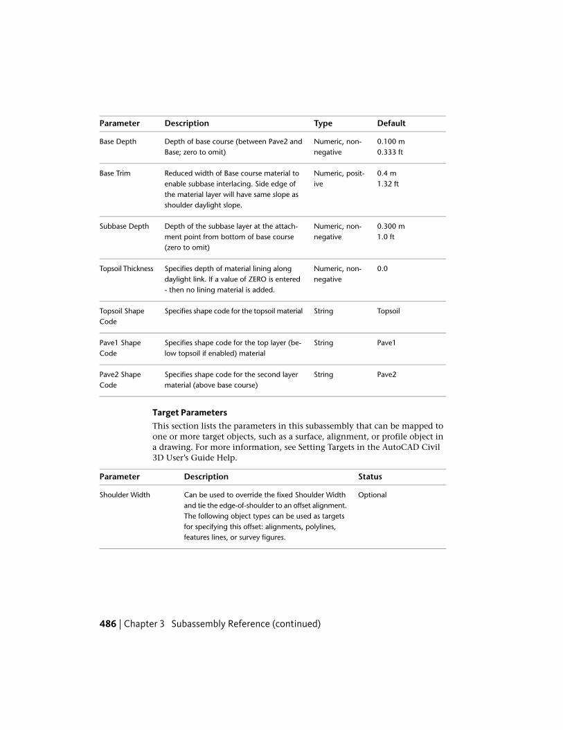
DefaultTypeDescriptionParameter
0.100 mNumeric, non-negative
Depth of base course (between Pave2 andBase; zero to omit)
Base Depth0.333 ft
0.4 mNumeric, posit-ive
Reduced width of Base course material toenable subbase interlacing. Side edge of
Base Trim1.32 ft
the material layer will have same slope asshoulder daylight slope.
0.300 mNumeric, non-negative
Depth of the subbase layer at the attach-ment point from bottom of base course(zero to omit)
Subbase Depth1.0 ft
0.0Numeric, non-negative
Specifies depth of material lining alongdaylight link. If a value of ZERO is entered- then no lining material is added.
Topsoil Thickness
TopsoilStringSpecifies shape code for the topsoil materialTopsoil ShapeCode
Pave1StringSpecifies shape code for the top layer (be-low topsoil if enabled) material
Pave1 ShapeCode
Pave2StringSpecifies shape code for the second layermaterial (above base course)
Pave2 ShapeCode
Target ParametersThis section lists the parameters in this subassembly that can be mapped toone or more target objects, such as a surface, alignment, or profile object ina drawing. For more information, see Setting Targets in the AutoCAD Civil3D User’s Guide Help.
StatusDescriptionParameter
OptionalCan be used to override the fixed Shoulder Widthand tie the edge-of-shoulder to an offset alignment.
Shoulder Width
The following object types can be used as targetsfor specifying this offset: alignments, polylines,features lines, or survey figures.
486 | Chapter 3 Subassembly Reference (continued)
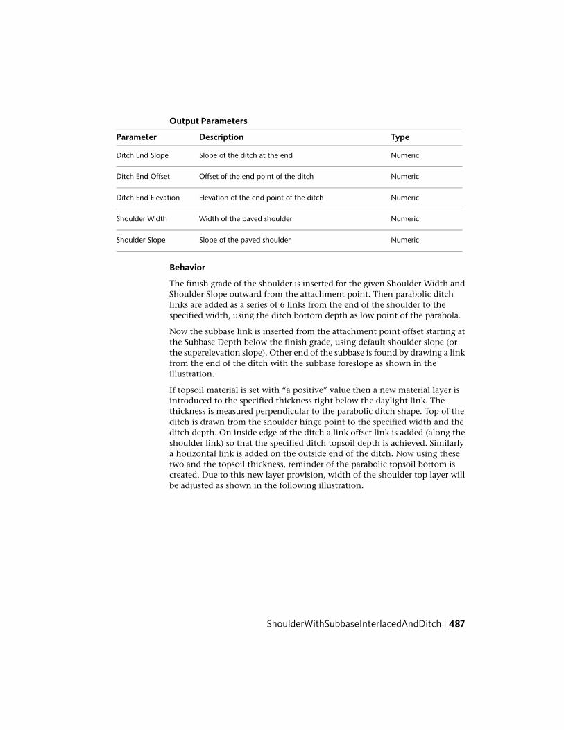
Output Parameters
TypeDescriptionParameter
NumericSlope of the ditch at the endDitch End Slope
NumericOffset of the end point of the ditchDitch End Offset
NumericElevation of the end point of the ditchDitch End Elevation
NumericWidth of the paved shoulderShoulder Width
NumericSlope of the paved shoulderShoulder Slope
Behavior
The finish grade of the shoulder is inserted for the given Shoulder Width andShoulder Slope outward from the attachment point. Then parabolic ditchlinks are added as a series of 6 links from the end of the shoulder to thespecified width, using the ditch bottom depth as low point of the parabola.
Now the subbase link is inserted from the attachment point offset starting atthe Subbase Depth below the finish grade, using default shoulder slope (orthe superelevation slope). Other end of the subbase is found by drawing a linkfrom the end of the ditch with the subbase foreslope as shown in theillustration.
If topsoil material is set with “a positive” value then a new material layer isintroduced to the specified thickness right below the daylight link. Thethickness is measured perpendicular to the parabolic ditch shape. Top of theditch is drawn from the shoulder hinge point to the specified width and theditch depth. On inside edge of the ditch a link offset link is added (along theshoulder link) so that the specified ditch topsoil depth is achieved. Similarlya horizontal link is added on the outside end of the ditch. Now using thesetwo and the topsoil thickness, reminder of the parabolic topsoil bottom iscreated. Due to this new layer provision, width of the shoulder top layer willbe adjusted as shown in the following illustration.
ShoulderWithSubbaseInterlacedAndDitch | 487

The Pave1, Pave2, and Base surface links are inserted parallel to the finishgrade at the given depths. Bottom of the Pave1 link is always extended to thedaylight link. If Pave 2 and/or Base Trim values are set to zero value – thenthe top links of these layers will be extended to the offset of “bottom link ofthe previous layer”. Bottom links of these layers are extended such that slopeof the wedge formed on the side is same as the ditch start grade (Note: computethe start grade of the parabolic ditch using three known points of the parabolicequation).
If the above trim values are set for a positive value then top of respectivematerial will be shortened by that value and the bottom link will be derivedwith material side slope equal to the daylight slope.
Further, if the “gap between Pave1/Pave2 and/or Pave2/Base” is set to a positivevalue – then those lavers will be separated by that gap as explained inShoulderWithSubbaseInterlaced subassembly.
Layout Mode Operation
In layout mode this subassembly displays the links comprising the shoulderwith default parameters assigned to it.
Point, Link, and Shape CodesThe following table lists the point, link, and shape codes for this subassemblythat have codes assigned to them. Point, link, or shape codes for thissubassembly that do not have codes assigned are not included in this table.
DescriptionCodesType
Edge of paved shoulder, finish gradeEPSP2
Subbase daylight pointDaylight_SubP3
Edge of paved shoulder on Pave1EPS_Pave1P5
488 | Chapter 3 Subassembly Reference (continued)

DescriptionCodesType
Edge of paved shoulder on Pave2EPS_Pave2P7
Edge of paved shoulder on BaseEPS_BaseP9
Finish grade of the shoulderTopL1, L2
Datum, SubbaseL3, L4
Pave1L5
Pave2L6
BaseL7
User defined code for top layer of shoulder (default - Pave1)User Defined CodeS1
User defined code for second layer of shoulder (default - Pave2)User Defined CodeS2
BaseS3
SubbaseS4
User defined code for topsoil material (default - Topsoil)User Defined CodeS5
ShoulderWithSubbaseInterlacedAndDitch | 489

Coding Diagram
SideDitchThe subassembly is used to create a ditch structure with optional backslopeand foreslopes.
490 | Chapter 3 Subassembly Reference (continued)
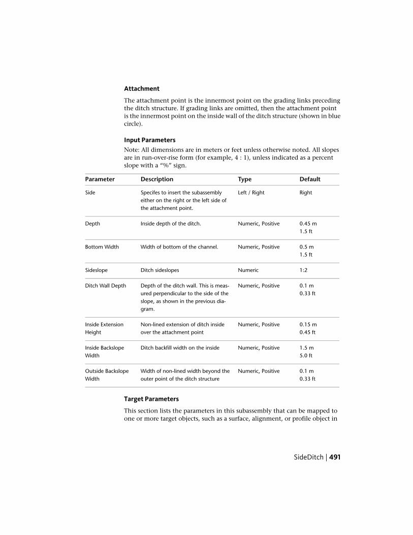
Attachment
The attachment point is the innermost point on the grading links precedingthe ditch structure. If grading links are omitted, then the attachment pointis the innermost point on the inside wall of the ditch structure (shown in bluecircle).
Input ParametersNote: All dimensions are in meters or feet unless otherwise noted. All slopesare in run-over-rise form (for example, 4 : 1), unless indicated as a percentslope with a “%” sign.
DefaultTypeDescriptionParameter
RightLeft / RightSpecifes to insert the subassemblyeither on the right or the left side ofthe attachment point.
Side
0.45 mNumeric, PositiveInside depth of the ditch.Depth1.5 ft
0.5 mNumeric, PositiveWidth of bottom of the channel.Bottom Width1.5 ft
1:2NumericDitch sideslopesSideslope
0.1 mNumeric, PositiveDepth of the ditch wall. This is meas-ured perpendicular to the side of the
Ditch Wall Depth0.33 ft
slope, as shown in the previous dia-gram.
0.15 mNumeric, PositiveNon-lined extension of ditch insideover the attachment point
Inside ExtensionHeight 0.45 ft
1.5 mNumeric, PositiveDitch backfill width on the insideInside BackslopeWidth 5.0 ft
0.1 mNumeric, PositiveWidth of non-lined width beyond theouter point of the ditch structure
Outside BackslopeWidth 0.33 ft
Target Parameters
This section lists the parameters in this subassembly that can be mapped toone or more target objects, such as a surface, alignment, or profile object in
SideDitch | 491

a drawing. For more information, see Setting Targets in the AutoCAD Civil3D User’s Guide Help.
Target Parameters: None.
Output Parameters
None.
Behavior
The subassembly builds the shape for a ditch structure, as shown in the aboveillustration.
NOTE In Civil 3D 2010 and previous versions, the Ditch Wall Depth parameterwas measured vertically. In Civil 3D 2011 and later, this parameter is measuredperpendicular to the side of the slope. Therefore, if you open a drawing containingthese subassemblies that was created in Civil 3D 2010 or prior in Civil 3D 2011or later, and then rebuild the corridor(s), this parameter will be changed to reflectthe new behavior. Any volume reports that use this subassembly will be updatedto reflect the new behavior.
Layout Mode Operation
In layout mode, this subassembly is created outward, starting from theattachment point, as defined using the input parameters.
Point, Link, and Shape CodesThe following table lists the point, link, and shape codes for this subassemblythat have codes assigned to them. Point, link, or shape codes for thissubassembly that do not have codes assigned are not included in this table.
DescriptionCodesPoint/Link
Ditch_BackP1, P6
Ditch_FaceP2, P5
Ditch_InP10
Ditch_OutP11
Top, DatumL9, L10, L11
Top, Ditch_TopL1 to L5
492 | Chapter 3 Subassembly Reference (continued)
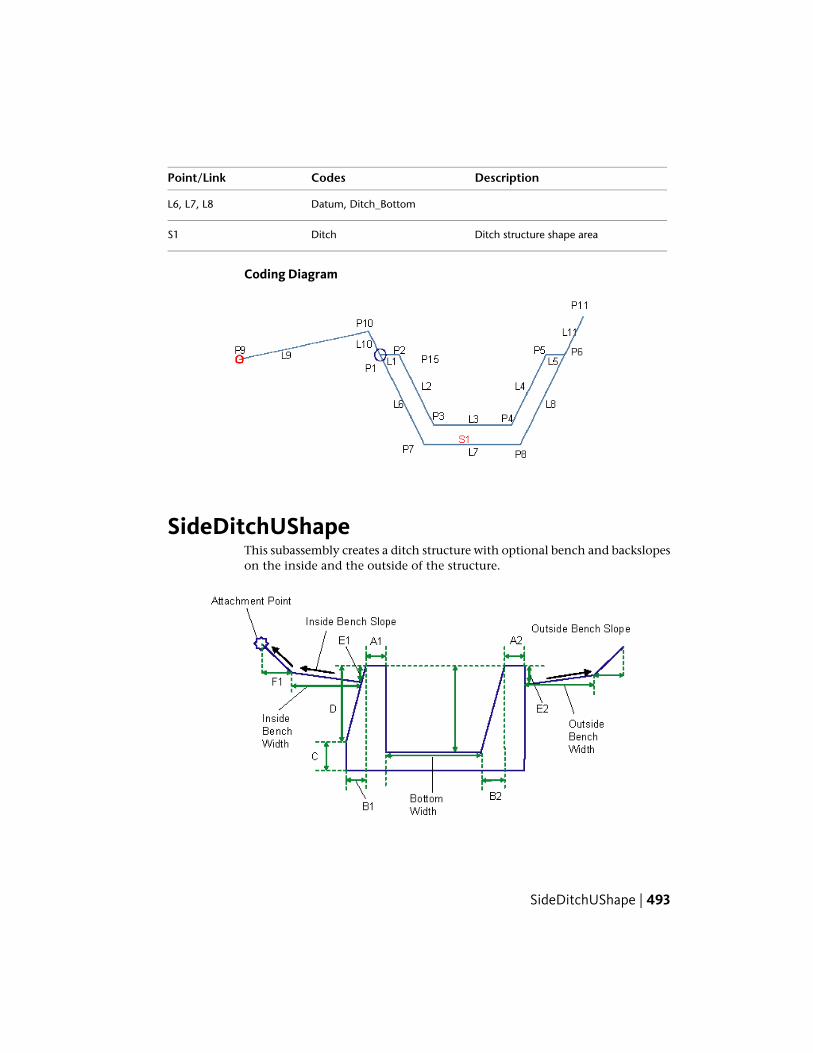
DescriptionCodesPoint/Link
Datum, Ditch_BottomL6, L7, L8
Ditch structure shape areaDitchS1
Coding Diagram
SideDitchUShapeThis subassembly creates a ditch structure with optional bench and backslopeson the inside and the outside of the structure.
SideDitchUShape | 493

Attachment
The attachment point is the innermost point of the optional inside bench. Ifinside benches are omitted, the attachment point is on the innermost pointof the inside wall of the ditch structure.
Input ParametersNote: All dimensions are in meters or feet unless otherwise noted. All slopesare in run-over-rise form (for example, 4 : 1), unless indicated as a percentslope with a “%” sign.
DefaultTypeDescriptionParameter
RightLeft / RightSpecifes to insert the subassemblyeither on the right or the left side ofthe attachment point.
Side
2.0 ftNumeric, PositiveBottom width of the ditchBottom Width0.6 m
2.0 ftNumeric, PositiveDepth of the ditchDitch Depth0.6 m
0.45 ftNumeric, PositiveThickness of the inside wall at the topA10.15m
0.6 ftNumeric, PositiveIncreased wall thickness of the insidewall at the bottom
B10.2m
0.5 ftNumeric, PositiveThickness of ditch bottom liningC0.15 m
2.0 ftNumeric, PositiveDepth of the tapered face on the in-side wall
D0.6 m
0.0 ftNumeric, PositiveDepth of the hinge point where thestart of inside bench/backslope linksis located
E10.0 m
1.5 ftNumeric, positiveWidth of the (optional) inside bench.Enter ZERO for no bench
Inside BenchWidth 0.5 m
4%Numeric, Grade typeCross grade of the (optional) insidebench. It is measured away from the
Inside BenchGrade
494 | Chapter 3 Subassembly Reference (continued)

DefaultTypeDescriptionParameter
ditch structure edge, and a positiveslope indicates rising bench from theditch
1.0 ftNumeric, PositiveInside backslope link (optional)width. Enter ZERO value for nobackslope link
F10.3 m
1:1Numeric, Slope typeSlope of the (optional) inside back-slope link. It is measured away from
G1
the ditch structure, and a positiveslope indicates rising link from thestart point
0.45 ftNumeric, PositiveThickness of the inside wall at the topA20.15 m
0.6 ftNumeric, PositiveTapered width of the outside wallB20.2 m
1.0 ftNumeric, PositiveDepth of the hinge point for the startof outside bench/backslope links
E20.3 m
3.0 ftNumeric, positiveWidth of the (optional) outsidebench. Enter ZERO for no bench
Outside BenchWidth 1.0 m
4%Numeric, Grade typeCross grade of the (optional) outsidebench. It is measured away from the
Outside BenchGrade
ditch structure edge, and a positiveslope indicates rising bench from theditch
1.0 ftNumeric, PositiveOutside backslope link (optional)width. Enter ZERO value for nobackslope link
F20.3 m
1:1Numeric, Slope typeSlope of the (optional) outside back-slope link. It is measured away from
G2
the ditch structure, and a positiveslope indicates rising link from thestart point
SideDitchUShape | 495

Target Parameters
This section lists the parameters in this subassembly that can be mapped toone or more target objects, such as a surface, alignment, or profile object ina drawing. For more information, see Setting Targets in the AutoCAD Civil3D User’s Guide Help.
Target Parameters: None.
Output Parameters
Behavior
The subassembly builds the shape for a ditch structure, as shown in theillustration. To omit benching and foreslope links, enter zero for theappropriate width parameters.
Layout Mode Operation
In layout mode, this subassembly draws as it is defined using the inputparameters, starting from the attachment point.
Point, Link, and Shape CodesThe following table lists the point, link, and shape codes for this subassemblythat have codes assigned to them. Point, link, or shape codes for thissubassembly that do not have codes assigned are not included in this table.
DescriptionCodesPoint/Link
Ditch_InP10
Ditch_BackP1, P6
Ditch_FaceP2, P5
Ditch_OutP14
TopL10, L13
If the offsets of P11 is < P8; and P13 is > P9respectively
DatumL10, L13
TopL11
TopL12
496 | Chapter 3 Subassembly Reference (continued)
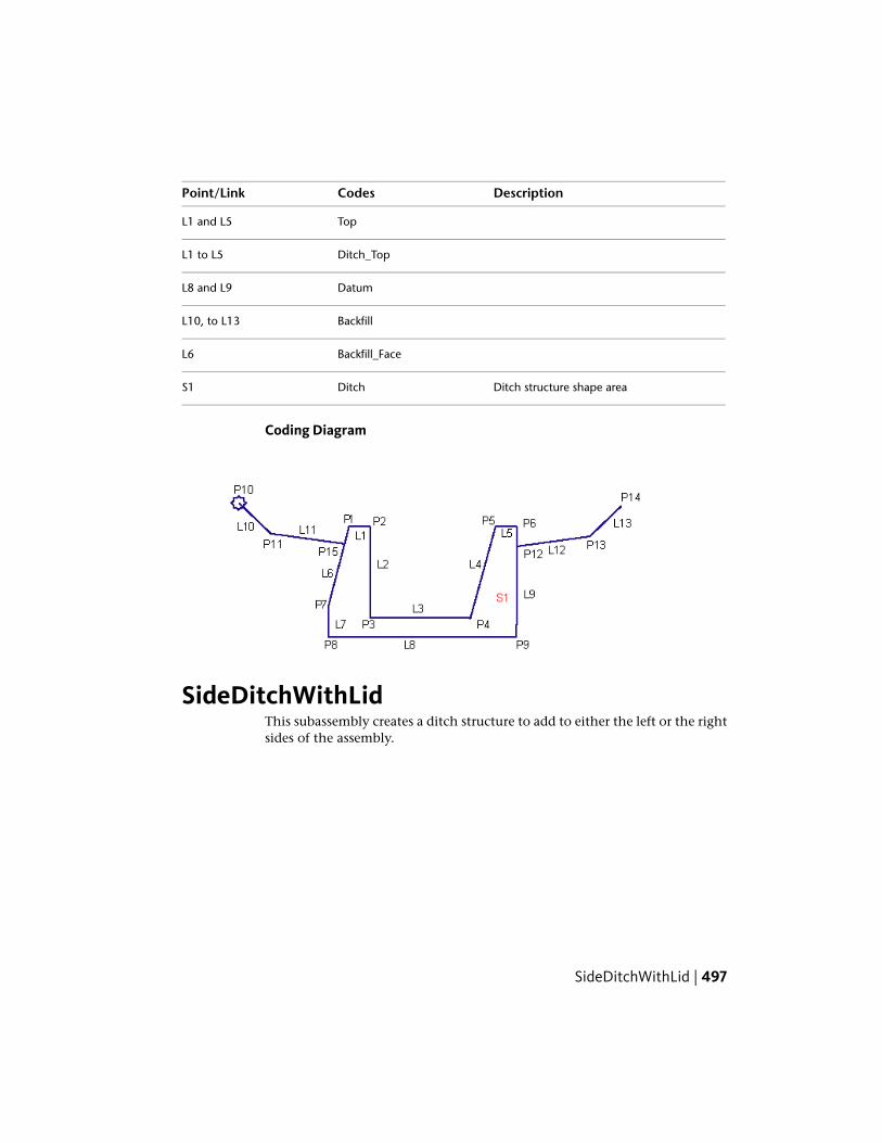
DescriptionCodesPoint/Link
TopL1 and L5
Ditch_TopL1 to L5
DatumL8 and L9
BackfillL10, to L13
Backfill_FaceL6
Ditch structure shape areaDitchS1
Coding Diagram
SideDitchWithLidThis subassembly creates a ditch structure to add to either the left or the rightsides of the assembly.
SideDitchWithLid | 497

Optionally, this subassembly can add daylight links on either side of thestructure.
Attachment
The attachment point is at the innermost point on the grading links precedingthe ditch structure. If the grading links on the inside are omitted, then theattachment point is on the innermost point of the inside wall.
Input ParametersNote: All dimensions are in meters or feet unless otherwise noted. All slopesare in run-over-rise form (for example, 4 : 1), unless indicated as a percentslope with a “%” sign.
DefaultTypeDescriptionParameter
RightLeft / RightSpecifes to insert the sub-assembly either on the right
Side
or the left side of the attach-ment point.
2.0ftNumeric, PositiveDepth of the ditch on theinside
Ditch Depth0.6m
1.0ftNumeric, PositiveBottom width of the ditchBottom Width0.3m
498 | Chapter 3 Subassembly Reference (continued)
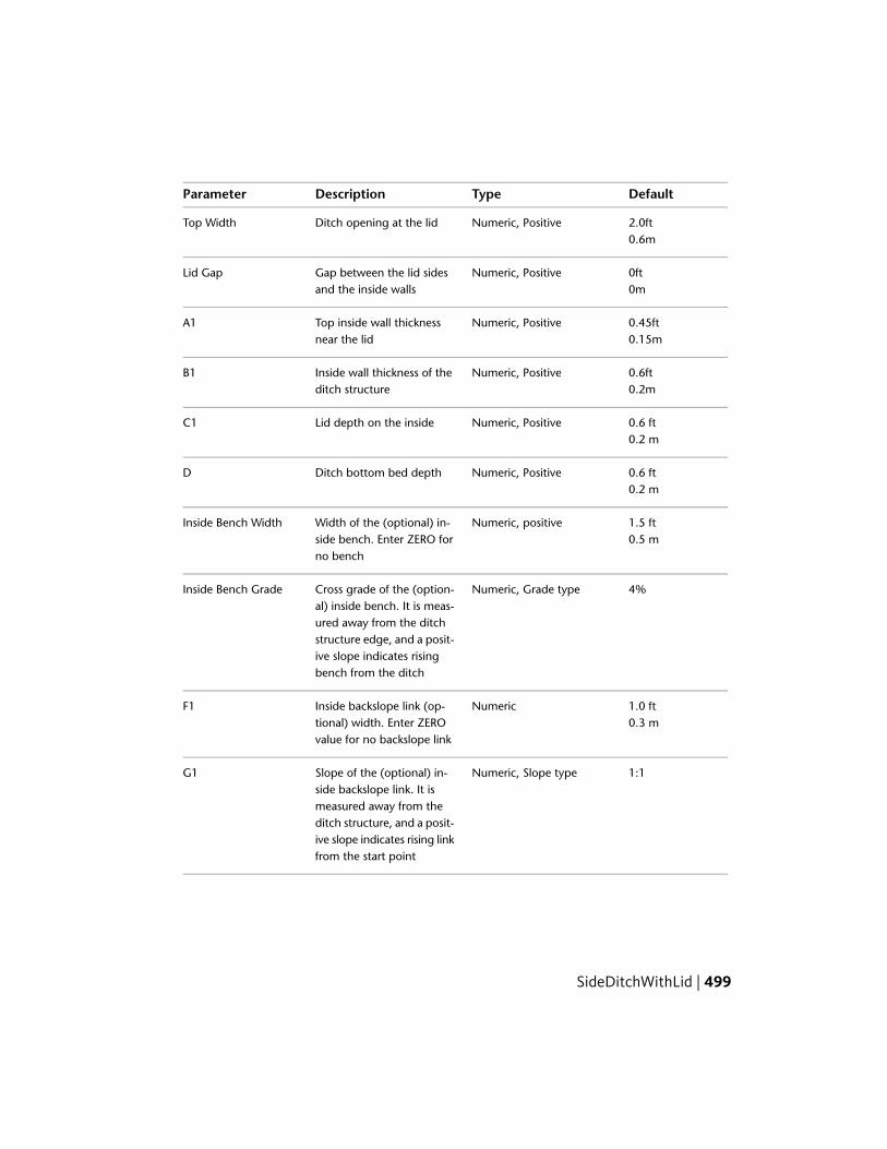
DefaultTypeDescriptionParameter
2.0ftNumeric, PositiveDitch opening at the lidTop Width0.6m
0ftNumeric, PositiveGap between the lid sidesand the inside walls
Lid Gap0m
0.45ftNumeric, PositiveTop inside wall thicknessnear the lid
A10.15m
0.6ftNumeric, PositiveInside wall thickness of theditch structure
B10.2m
0.6 ftNumeric, PositiveLid depth on the insideC10.2 m
0.6 ftNumeric, PositiveDitch bottom bed depthD0.2 m
1.5 ftNumeric, positiveWidth of the (optional) in-side bench. Enter ZERO forno bench
Inside Bench Width0.5 m
4%Numeric, Grade typeCross grade of the (option-al) inside bench. It is meas-
Inside Bench Grade
ured away from the ditchstructure edge, and a posit-ive slope indicates risingbench from the ditch
1.0 ftNumericInside backslope link (op-tional) width. Enter ZEROvalue for no backslope link
F10.3 m
1:1Numeric, Slope typeSlope of the (optional) in-side backslope link. It is
G1
measured away from theditch structure, and a posit-ive slope indicates rising linkfrom the start point
SideDitchWithLid | 499

DefaultTypeDescriptionParameter
0.45 ftNumeric, PositiveTop outside wall thicknessnear the lid
A20.15 m
0.6 ftNumeric, PositiveOutside wall thickness ofthe ditch structure
B20.2 m
0.45 ftNumeric, PositiveLid depth on the outsideC20.15 m
0 ftNumeric, PositiveDepth of the hinge pointwhere the start of outside
E0 m
bench/backslope links islocated
3.5ftOutside Bench WidthWidth of the (optional)outside bench. Enter ZEROfor no bench
Outside Bench Width1.1m
4%Outside Bench GradeCross grade of the (option-al) outside bench. It is
Outside Bench Grade
measured away from theditch structure edge, and apositive slope indicatesrising bench from the ditch
0.3Numeric, PositiveOutside backslope link (op-tional) width. Enter ZEROvalue for no backslope link
F2
1 : 1Numeric, Slope typeSlope of the (optional) out-side backslope link. It is
G2
measured away from theditch structure, and a posit-ive slope indicates rising linkfrom the start point
Target Parameters
This section lists the parameters in this subassembly that can be mapped toone or more target objects, such as a surface, alignment, or profile object in
500 | Chapter 3 Subassembly Reference (continued)
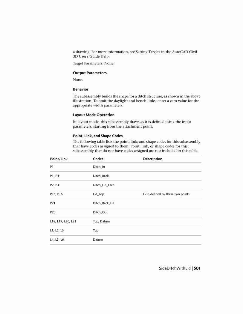
a drawing. For more information, see Setting Targets in the AutoCAD Civil3D User’s Guide Help.
Target Parameters: None.
Output Parameters
None.
Behavior
The subassembly builds the shape for a ditch structure, as shown in the aboveillustration. To omit the daylight and bench links, enter a zero value for theappropriate width parameters.
Layout Mode Operation
In layout mode, this subassembly draws as it is defined using the inputparameters, starting from the attachment point.
Point, Link, and Shape CodesThe following table lists the point, link, and shape codes for this subassemblythat have codes assigned to them. Point, link, or shape codes for thissubassembly that do not have codes assigned are not included in this table.
DescriptionCodesPoint/Link
Ditch_InP1
Ditch_BackP1, P4
Ditch_Lid_FaceP2, P3
L2 is defined by these two pointsLid_TopP15, P16
Ditch_Back_FillP21
Ditch_OutP23
Top, DatumL18, L19, L20, L21
TopL1, L2, L3
DatumL4, L5, L6
SideDitchWithLid | 501
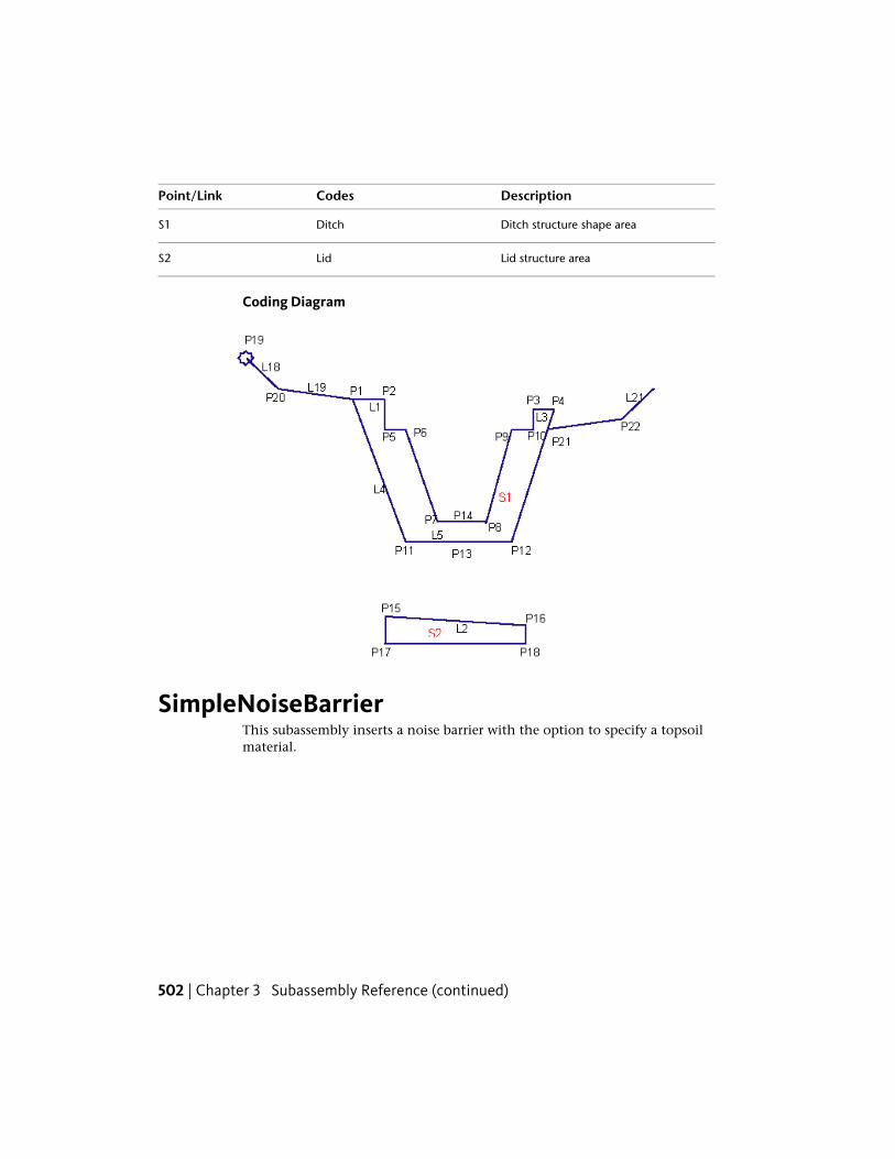
DescriptionCodesPoint/Link
Ditch structure shape areaDitchS1
Lid structure areaLidS2
Coding Diagram
SimpleNoiseBarrierThis subassembly inserts a noise barrier with the option to specify a topsoilmaterial.
502 | Chapter 3 Subassembly Reference (continued)

Attachment
The attachment point is at the inside edge of the barrier, which is typicallyat the outside edge-of-traveled way or shoulder or another road element.
Input Parameters
Note: All dimensions are in meters or feet unless otherwise noted. All slopesare in run-over-rise form (for example, 4 : 1), unless indicated as a percentslope with a “%” sign.
DefaultTypeDescriptionParameter
RightLeft/RightSpecifes to insert the subassemblyeither on the right or the left sideof the attachment point.
Side
1.0mNumeric, Posit-ive
Width of the top barrier top.Top Width3.0 ft
1:1.5NumericDefault slope of the barrierforeslope link.
Foreslope
1:1.5NumericDefault slope of the barrier backslope link.
Backslope
3.00mNumeric, Posit-ive
Specifies height of the barriermeasure from the attachmentpoint elevation.
Height9.00ft
0.0Numeric, posit-ive
Specifies depth of material liningalong daylight link. If a value of
TopsoilThickness
SimpleNoiseBarrier | 503

DefaultTypeDescriptionParameter
zero is entered, then no liningmaterial is added.
TopsoilStringSpecifies shape code for the top-soil material
TopsoilShapeCode
Target ParametersThis section lists the parameters in this subassembly that can be mapped toone or more target objects, such as a surface, alignment, or profile object ina drawing. For more information, see Setting Targets in the AutoCAD Civil3D User’s Guide Help.
StatusDescriptionParameter
OptionalCan be used to tie in the back of the barrierinto an existing surface at the user defined
Target Surface
slope. The following object types can be usedas targets for specifying this surfaces: surfaces.
Output Parameters
TypeDescriptionParameter
NumericElevation of the mid point of the barrier top linkBarrier Top Elevation
NumericOffset of the mid point of the barrier top linkBarrier Top Offset
NumericThickness of topsoil materialTopsoil Thickness
NumericSlope of the noise barrier backslope linkBackslope
NumericOffset of the end point of the noise barrier.Barrier End Offset
NumericElevation of the end point of the noise barrierBarrier End Elevation
Behavior
This noise barrier is introduced from the attachment point with the foreslopeand backslope as specified by the user. If the Top width is set to zero value,then a triangular shaped noise barrier results. Further if a topsoil layer is
504 | Chapter 3 Subassembly Reference (continued)

selected for this subassembly – then a lined material layer is introduced asillustrated below. (Note: a horizontal link at the attachment point is introducedsuch that the thickness of the material is equal to the specified value).
If the backslope is tied into a surface, then that side height is adjusted todaylight into the surface as shown below.
If the backslope is not tied into any surface, then the height of that side is setwith specified height. Further, if the surface at that point is higher than thetop of the barrier then again backslope link is drawn downwards with specifiedslope and height parameters.
Layout Mode Operation
In layout mode, this subassembly draws the links showing the defaultparameters, including height for back slope.
SimpleNoiseBarrier | 505

Point, Link, and Shape CodesThe following table lists the point, link, and shape codes for this subassemblythat have codes assigned to them. Point, link, or shape codes for thissubassembly that do not have codes assigned are not included in this table.
DescriptionCodesType
Top point of the barrierRW_TopP2
Subbase daylight pointRW_OutsideP3
Only if Target Surface is setDaylightP3
Inside edge of the barrier top (only if Top Width is non-zerovalue)
Bench_InP4
Outside edge of the barrier top (only if Top Width is non-zerovalue)
Bench_OutP5
Finish grade of the shoulderTopL1, L2,L3
Only if the topsoil is thickness is set to zeroDatumL1, L2,L3
Only if the topsoil thickness is set to Positive valueDatumL4 to L7
Only if Target Surface is not setDatumL8
User defined code for topsoil (default - Topsoil)User Defined CodeS1
506 | Chapter 3 Subassembly Reference (continued)

Coding Diagram
StrippingPavementThis subassembly is used to specify the existing top layer stripping to a specifieddepth.
StrippingPavement | 507

Optionally, this subassembly can extend the stripping back to the existingground with a specified backslope.
Attachment
The attachment point is at the daylight point on the finish grade.
Input Parameters
Note: All dimensions are in meters or feet unless otherwise noted. All slopesare in run-over-rise form (for example, 4 : 1), unless indicated as a percentslope with a “%” sign.
DefaultTypeDescriptionParameter
0.05mNumericSpecifies depth of the topsoil toremove.
Stripping Depth0.167ft
508 | Chapter 3 Subassembly Reference (continued)

DefaultTypeDescriptionParameter
YesBooleanSpecifies to extend the strippingback to existing ground
Extend to Existing Ground
-2 (:1)NumericDefault foreslope of the strippingextension from original daylight
Foreslope
point to beginning of backslope.
2 (:1)Numeric, positiveBackslope to grade from bottomof stripping back into the exist-ing ground
Backslope
Target ParametersThis section lists the parameters in this subassembly that can be mapped toone or more target objects, such as a surface, alignment, or profile object ina drawing. For more information, see Setting Targets in the AutoCAD Civil3D User’s Guide Help.
StatusDescriptionParameter
RequiredName of the existing surface to grade backfrom bottom of stripping. The following object
Existing Surface
types can be used as targets for specifying thissurfaces: surfaces.
Output Parameters
None.
Behavior
This subassembly inserts parallel links defining the bottom of the strippinglayer below a specified surface. If the option to extend stripping to the existingground with a backslope is set to No, then stripping starts at the attachmentpoint directly on the specified surface, with a vertical link with depth valuespecified in the input parameters. From the bottom of this vertical link, aseries of links parallel to the specified surface are introduced inwards, untilthe baseline location of the assembly. If the option to extend stripping to theexisting ground is set to Yes, then at the attachment point, a link is introducedwith the specified foreslope, until the elevation difference between the bottomof this new link and the specified existing ground is equal to the “stripping
StrippingPavement | 509
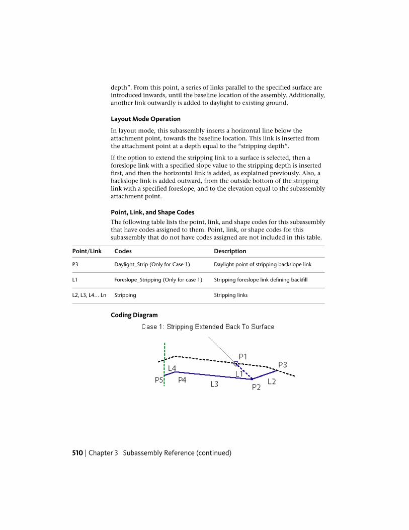
depth”. From this point, a series of links parallel to the specified surface areintroduced inwards, until the baseline location of the assembly. Additionally,another link outwardly is added to daylight to existing ground.
Layout Mode Operation
In layout mode, this subassembly inserts a horizontal line below theattachment point, towards the baseline location. This link is inserted fromthe attachment point at a depth equal to the “stripping depth”.
If the option to extend the stripping link to a surface is selected, then aforeslope link with a specified slope value to the stripping depth is insertedfirst, and then the horizontal link is added, as explained previously. Also, abackslope link is added outward, from the outside bottom of the strippinglink with a specified foreslope, and to the elevation equal to the subassemblyattachment point.
Point, Link, and Shape CodesThe following table lists the point, link, and shape codes for this subassemblythat have codes assigned to them. Point, link, or shape codes for thissubassembly that do not have codes assigned are not included in this table.
DescriptionCodesPoint/Link
Daylight point of stripping backslope linkDaylight_Strip (Only for Case 1)P3
Stripping foreslope link defining backfillForeslope_Stripping (Only for case 1)L1
Stripping linksStrippingL2, L3, L4… Ln
Coding Diagram
510 | Chapter 3 Subassembly Reference (continued)
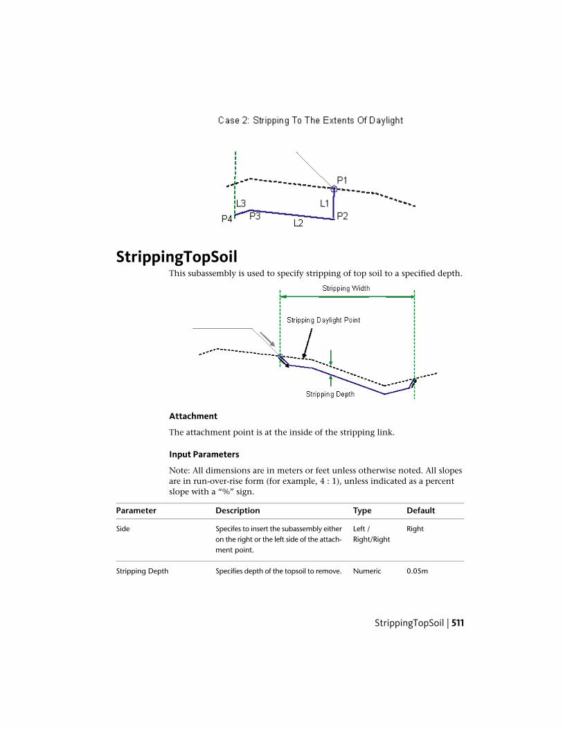
StrippingTopSoilThis subassembly is used to specify stripping of top soil to a specified depth.
Attachment
The attachment point is at the inside of the stripping link.
Input Parameters
Note: All dimensions are in meters or feet unless otherwise noted. All slopesare in run-over-rise form (for example, 4 : 1), unless indicated as a percentslope with a “%” sign.
DefaultTypeDescriptionParameter
RightLeft /Right/Right
Specifes to insert the subassembly eitheron the right or the left side of the attach-ment point.
Side
0.05mNumericSpecifies depth of the topsoil to remove.Stripping Depth
StrippingTopSoil | 511
DefaultTypeDescriptionParameter
0.167ft
5mNumericSpecifies width of the topsoil strippingregion.
Stripping Width16.67ft
-2 (:1)NumericDefault foreslope of the stripping exten-sion from original daylight point to be-ginning of back slope.
Foreslope
2 (:1)Numeric,positive
Backslope to grade from bottom ofstripping back into the existing ground
Backslope
Target ParametersThis section lists the parameters in this subassembly that can be mapped toone or more target objects, such as a surface, alignment, or profile object ina drawing. For more information, see Setting Targets in the AutoCAD Civil3D User’s Guide Help.
StatusDescriptionParameter
OptionalMay be used to override the fixed Stripping Width andtie to an offset alignment. The following object types
Stripping Width
can be used as targets for specifying this offset: align-ments, polylines, features lines, or survey figures.
RequiredName of the existing surface to grade back from bottomof stripping. The following object types can be used astargets for specifying this surfaces: surfaces.
Existing Surface
Output Parameters
None.
Behavior
This subassembly inserts parallel links defining the bottom of the strippinglayer below a specified surface. The stripping starts at the insertion point justbelow the specified surface. A foreslope link is placed from the insertion pointto the side specified in the input parameters. This link is drawn until theelevation difference between its lowest point and the existing ground is equalto the “stripping depth”.
512 | Chapter 3 Subassembly Reference (continued)

Similarly, a backslope link is drawn from the topsoil surface at an offestspecified by the “stripping width” from the insertion point. Again the depthof this link is such that the elevation difference at the bottom of the link, withrespect to the topsoil surface, is equal to the stripping depth.
Now a series of links parallal to the specified topsoil surface are introducedconnecting above two new links to define the stripping layer.
To insert vertical links at the insertion point, and or at the other end of thestripping, specify foreslope and or backslope values to zero.
Layout Mode Operation
In layout mode, foreslope and backslope links are added using the inputparameters. Connecting the bottom of these two links, a horizontal line isadded to represent the stripping layer.
Point, Link, and Shape CodesThe following table lists the point, link, and shape codes for this subassemblythat have codes assigned to them. Point, link, or shape codes for thissubassembly that do not have codes assigned are not included in this table.
DescriptionCodesPoint/Link
Daylight point of stripping backslope linkDaylight_StripP2
Stripping linksStrippingAll Links
Coding Diagram
TrenchPipe1This subassembly creates a flat-bottom trench with equal sideslopes and upto three layers of backfill material.
TrenchPipe1 | 513

Attachment
The attachment point is at the Offset To Bottom distance above the midpointof the base of the trench.
Input ParametersNote: All dimensions are in meters or feet unless otherwise noted. All slopesare in run-over-rise form (for example, 4 : 1) unless indicated as a percentslope with a “%” sign.
DefaultTypeDescriptionParameter
2.0 mNumeric,positive
Width of the bottom of the trenchWidth6.0 ft
3 : 1Numeric,positive
X : 1 slope of the trench sideslopesSideslope
0.0Numeric,positive
Depth of the bedding layerBedding Depth
0.0Numeric,positive
Depth of the special backfill layerSpecial BackfillDepth
0.0NumericThe vertical offset down from the profile grade lineelevation to the bottom of the trench. For example,
Offset to Bottom
if the profile runs along the top of a circular pipe,the vertical offset is the pipe diameter plus the dis-
514 | Chapter 3 Subassembly Reference (continued)

DefaultTypeDescriptionParameter
tance from the bottom of the pipe to the bottomof the trench.
Behavior
The elevation of the bottom of the trench is calculated as the profile gradeline elevation minus the Offset To Bottom value. The horizontal trench bottomlink is placed symmetrically about the attachment point offset at that elevation,and the sideslopes are extended upward to the Existing Surface. The horizontalBedding link is placed at the given depth above the trench bottom. Thehorizontal Special Backfill link is placed at the given depth above the Beddinglink.
Target ParametersThis section lists the parameters in this subassembly that can be mapped toone or more target objects, such as a surface, alignment, or profile object ina drawing. For more information, see Setting Targets in the AutoCAD Civil3D User’s Guide Help.
StatusDescriptionParameter
RequiredSurface model defining the existing roadwaysurface. The following object types can be usedas targets for specifying this surfaces: surfaces.
Existing Surface
Output Parameters
None.
Layout Mode Operation
In layout mode, the trench and existing surface are drawn as shown below.
TrenchPipe1 | 515

Point, Link, and Shape CodesThe following table lists the point, link, and shape codes for this subassemblythat have codes assigned to them. Point, link, or shape codes for thissubassembly that do not have codes assigned are not included in this table.
DescriptionCodePoint / Link
Trench_BottomP1, P2
Trench_DaylightP3, P4
Trench_BeddingP5, P6
Trench_BackfillP7, P8
Trench DatumL1 – L7
Trench_BottomL8
Trench_DaylightL9
Trench_BeddingS1
Trench_BackfillS2
516 | Chapter 3 Subassembly Reference (continued)

Coding Diagram
TrenchPipe2This subassembly creates a flat-bottom trench with equal sideslopes, and upto three layers of backfill material. The width of the trench is determined bya user- specified width and minimum pipe cover.
Attachment
The attachment point is located along the target surface in the middle of thetrench.
TrenchPipe2 | 517

Input ParametersNote: All dimensions are in meters or feet unless otherwise noted. All slopesare in run-over-rise form (for example, 4 : 1) unless indicated as a percentslope with a “%” sign.
DefaultTypeDescriptionParameter
3 : 1Numeric, positiveX : 1 slope of the trench sideslopesSideslope
0.0Numeric, positiveDepth of the bedding layerBedding Depth
0.0Numeric, positiveMinimum amount of special backfillcover placed over the highest outerpipe diameter.
Special Backfill Minim-um Cover
0.0Numeric, positiveMinimum depth for special backfillbelow lowest pipe. The pipe is
Special Backfill Minim-um Depth
measured from the pipe’s outerdiameter.
2.0 mNumeric, positiveWidth of the bottom of the trenchWidth6.0 ft
0.0Numeric, positiveOffset from the centerline of thepipe to the trench sideslope
Pipe Network 1 Offset
0.0Numeric, positiveOffset from the centerline of thepipe to the trench sideslope
Pipe Network 2 Offset
Target ParametersThis section lists the parameters in this subassembly that can be mapped toone or more target objects, such as a surface, alignment, or profile object ina drawing. For more information, see Setting Targets in the AutoCAD Civil3D User’s Guide Help.
StatusDescriptionParameter
RequiredExisting Ground surface to connect sideslopes to.The following object types can be used as targetsfor specifying this surface: surfaces.
Existing Surface
518 | Chapter 3 Subassembly Reference (continued)

StatusDescriptionParameter
RequiredUsed to specify Pipe Network 1. The following objecttypes can be used as targets for specifying this pipenetwork: pipe networks.
Pipe Network 1
OptionalUsed to Specify Pipe Network 2. The following ob-ject types can be used as targets for specifying thispipe network: pipe networks.
Pipe Network 2
Output Parameters
None.
Behavior
In both cases, the subassembly will determine the bottom of the trench depthand the trench width based on the location of a pipe (or pipes) in a specifiedpipe network. The Special Backfill Minimum Cover is determined by measuringthe distance from the centerline of the highest pipe found at the sampledsection. The Special Backfill Minimum Depth is determined by measuring thedistance from the bottom outer diameter of the lowest pipe found at thesampled station.
Case 1: Single Pipe Network Selected
If only Pipe Network 1 is selected, the subassembly will search 3 feet (1m)from the controlling baseline to the left and right to find the pipe center lineat the sampled station. Apply the Pipe Network 1 offset value to both sides todetermine the trench width, or the minimum width, whichever is larger. Thebottom of the trench is determined by the outer pipe diameter, plus the SpecialBackfill Minimum Depth, plus the Bedding Depth.
Case2: Two Pipe Networks Selected
TrenchPipe2 | 519
When two pipe networks are selected, Pipe Network 1 will be assumed to beon the left side of the baseline. Pipe network 2 will be assumed to be on theright side of the alignment. The material depth of the Special Backfill MinimumDepth is determined by the higher of the two pipe outer diameters, plus theSpecial Backfill Minimum Cover depth. The bottom of the trench depth isdetermined by the lower of the two pipe outer diameters, plus the SpecialBackfill Minimum Depth, plus the Bedding Depth.
Layout Mode Operation
In layout mode, this subassembly draws a trench as shown in the previousillustrations.
Point, Link, and Shape CodesThe following table lists the point, link, and shape codes for this subassemblythat have codes assigned to them. Point, link, or shape codes for thissubassembly that do not have codes assigned are not included in this table.
DescriptionCodesPoint/Link
Trench_BottomP1, P2
Trench_DaylightP3, P4
Trench_BeddingP5, P6
Trench_BackfillP7, P8
Trench DatumL1 - L7
Trench_BackfillL8
Trench_BeddingL9
Trench_BeddingS1
Trench_BackfillS2
520 | Chapter 3 Subassembly Reference (continued)
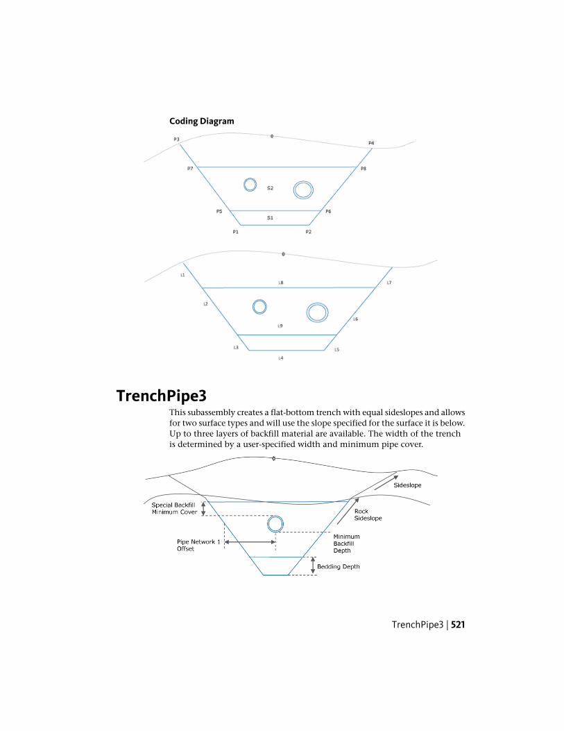
Coding Diagram
TrenchPipe3This subassembly creates a flat-bottom trench with equal sideslopes and allowsfor two surface types and will use the slope specified for the surface it is below.Up to three layers of backfill material are available. The width of the trenchis determined by a user-specified width and minimum pipe cover.
TrenchPipe3 | 521

Attachment
The attachment point is located along the target surface in the middle of thetrench.
Input ParametersNote: All dimensions are in meters or feet unless otherwise noted. All slopesare in run-over-rise form (for example, 4 : 1) unless indicated as a percentslope with a “%” sign.
DefaultTypeDescriptionParameter
3 : 1Numeric, positiveX : 1 slope of the trenchsideslopes
Sideslope
0.0Numeric, positiveDepth of the bedding layerBedding Depth
0.0Numeric, positiveMinimum amount of specialbackfill cover placed over the
Special Backfill MinimumCover
highest pipe. The pipe ismeasured from the pipe’s topouter diameter.
0.0Numeric, positiveMinimum depth for specialbackfill below the lowest
Special Backfill MinimumDepth
pipe. The pipe is measuredfrom the pipe’s bottom outerdiameter.
2.0 mNumeric, positiveWidth of the bottom of thetrench
Width6.0 ft
0.0Numeric, positiveOffset from the centerline ofthe pipe to the trenchsideslope
Pipe Network 1 Offset
0.0Numeric, positiveOffset from the centerline ofthe pipe to the trenchsideslope
Pipe Network 2 Offset
1 : 1Numeric, positiveX : 1 slope of the trench rocksideslopes
Sideslope Rock
522 | Chapter 3 Subassembly Reference (continued)
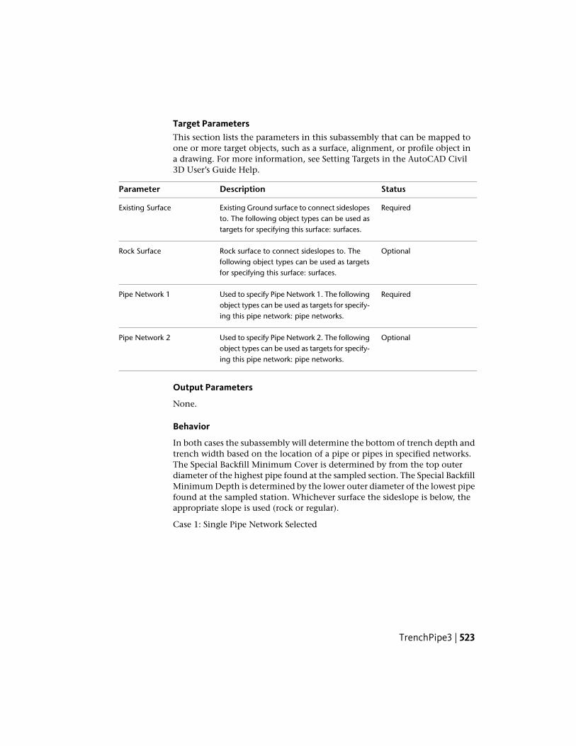
Target ParametersThis section lists the parameters in this subassembly that can be mapped toone or more target objects, such as a surface, alignment, or profile object ina drawing. For more information, see Setting Targets in the AutoCAD Civil3D User’s Guide Help.
StatusDescriptionParameter
RequiredExisting Ground surface to connect sideslopesto. The following object types can be used astargets for specifying this surface: surfaces.
Existing Surface
OptionalRock surface to connect sideslopes to. Thefollowing object types can be used as targetsfor specifying this surface: surfaces.
Rock Surface
RequiredUsed to specify Pipe Network 1. The followingobject types can be used as targets for specify-ing this pipe network: pipe networks.
Pipe Network 1
OptionalUsed to specify Pipe Network 2. The followingobject types can be used as targets for specify-ing this pipe network: pipe networks.
Pipe Network 2
Output Parameters
None.
Behavior
In both cases the subassembly will determine the bottom of trench depth andtrench width based on the location of a pipe or pipes in specified networks.The Special Backfill Minimum Cover is determined by from the top outerdiameter of the highest pipe found at the sampled section. The Special BackfillMinimum Depth is determined by the lower outer diameter of the lowest pipefound at the sampled station. Whichever surface the sideslope is below, theappropriate slope is used (rock or regular).
Case 1: Single Pipe Network Selected
TrenchPipe3 | 523

If only Pipe Network 1 is selected, the subassembly will search 3 feet (1 meter)from the controlling baseline to the left and right to find the pipe centerlineat the sampled station. Apply the Pipe Network 1 offset value to both sides todetermine the pipe width, or the minimum width, whichever is smaller. Thebottom of the trench is determined by the pipe bottom outer diameter, plusthe Special Backfill Minimum Depth, plus the Bedding Depth.
Case2: Two Pipe Networks Selected
When two pipe networks are selected, Pipe Network 1 will be assumed to beon the left side of the baseline, Pipe Network 2 will be assumed to be on theright side of the alignment. The material depth of the Special Backfill MinimumDepth will be determined by the higher of the two pipe top outer diameters,plus the Special Backfill Minimum Cover value. The bottom of the trenchdepth will be determined by the lower of the two pipe bottom outer diameters,plus the Special Backfill Minimum Depth, plus the Bedding Depth.
Layout Mode Operation
In layout mode, this subassembly draws a trench as shown in the previousillustrations.
524 | Chapter 3 Subassembly Reference (continued)

Point, Link, and Shape CodesThe following table lists the point, link, and shape codes for this subassemblythat have codes assigned to them. Point, link, or shape codes for thissubassembly that do not have codes assigned are not included in this table.
DescriptionCodesPoint/Link
Trench_BottomP1, P2
Trench_DaylightP3, P4
Trench_BeddingP5, P6
Trench_BackfillP7, P8
Trench DatumL1 - L9
Trench_BottomL5
Trench_DaylightL1,L9
Trench_BackfillL10
Trench_BeddingL11
Trench_BeddingS1
Trench backfill minus area of pipesTrench_BackfillS2
Coding Diagram
TrenchPipe3 | 525

TrenchWithPipeThis subassembly creates a stone-filled drain structure with a circular pipeinside.
Attachment
The attachment point for this subassembly can be at the bottom center, thetop center, or the top corner of the drain structure.
Input Parameters
Note: All dimensions are in meters or feet unless otherwise noted. All slopesare in run-over-rise form (for example, 4 : 1), unless indicated as a percentslope with a “%” sign.
DefaultTypeDescriptionParameter
RightLeft / RightSpecifes to insert the subassemblyeither on the right or the left side ofthe attachment point.
Side
Top cornerString; (a) Top center; (b)Bottom center, (c) Topcorner
Specifies location of subassembly at-tachment point.
Attachment Point
1.0 ftNumeric, PositiveBottom Width of the trenchBottom Width0.3 m
526 | Chapter 3 Subassembly Reference (continued)

DefaultTypeDescriptionParameter
1.5 ftNumeric, PositiveTop width of the trenchTop Width0.5 m
2.0 ftNumeric, PositiveTotal depth of the trenchDepth0.6 m
0.6 ftNumeric, PositiveDepth of the pipe bedding over trenchbottom
Bedding Depth0.2 m
0.6 ftNumeric, PositiveDrain pipe diameterPipe Diameter0.2 ft
0.0 ftNumeric, PositiveThickness of the pipe material (option-al)
Pipe Thickness0.0 m
Target ParametersThis section lists the parameters in this subassembly that can be mapped toone or more target objects, such as a surface, alignment, or profile object ina drawing. For more information, see Setting Targets in the AutoCAD Civil3D User’s Guide Help.
StatusDescriptionParameter
OptionalDepth of the trench can be optionally be overridden from aprofile elevation. If the attachment point is on the top of the
Depth
trench, then this profile is assigned for the trench bottomand vice-versa. The following object types can be used astargets for specifying this elevation: profiles, 3D polylines,feature lines, or survey figures.
Output Parameters
Behavior
The subassembly builds the shape for a simple drain structure as shown in theabove illustration.
Layout Mode Operation
In layout mode, this subassembly draws as it is defined using the inputparameters, starting from the attachment point.
TrenchWithPipe | 527

Point, Link, and Shape CodesThe following table lists the point, link, and shape codes for this subassemblythat have codes assigned to them. Point, link, or shape codes for thissubassembly that do not have codes assigned are not included in this table.
DescriptionCodesPoint/Link
Drain_BottomP1
Drain_Bottom_OutsideP2
Drain_Top_OutsideP3
Drain_Top_InsideP4
Drain_Bottom_InsideP5
Drain_CenterP6
Use existing point code, if any, among curband gutters.
Flow_LineP7
Top, Drain_TopL1
Datum, Drain_BottomL2, L3, L4
Trench_BackfillS1
Drain_AreaS2
528 | Chapter 3 Subassembly Reference (continued)

Coding Diagram
UrbanCurbGutterGeneralThis subassembly inserts links for a standard shape concrete curb-and-gutterwith subbase.
User-defined input parameters control the dimensions of the shape.
Attachment
The attachment point is at the flange point of the gutter or the back of thecurb.
UrbanCurbGutterGeneral | 529

Input ParametersNote: Subbase dimensions are in meters or feet. Curb-and-gutter dimensionsmust be given in millimeters or inches.
DefaultTypeDescriptionParameter
RightLeft/RightSpecifes to insert the subassembly either on theright or the left side of the attachment point.
Side
GutterEdge
BooleanSpecifies insertion point of the curb and gutter aseither Gutter Edge or Back of Curb
Insertion Point
Outsidelane super-
BooleanSpecifies method of gutter slope input as: Use out-side lane superelevation slope; Fixed slope; Usedepth of flow line from flange point.
Gutter SlopeMethod
elevationslope
- 2%NumericSpecifies fixed gutter slopeGutter Slope
0.450 mNumeric,positive
Depth to subbase at the flange point. Use zero ifthere is no subbase.
Subbase Depth1.5 ft
0.3 mNumeric,positive
Distance the subbase is extended beyond the back-of-curb. Use zero to terminate the subbase at theback-of-curb.
Subbase Exten-sion 1.0 ft
Use superel-evation
Selection listSelects whether to use the Outside Lane superelev-ation slope for the subbase layer, or to set a numeric% slope value
Use SE
-2 (%)Numeric% slope of the subbase layer. Not used if Use SE isset to True.
Subbase %Slope
175 mmNumeric,positive,
Depth of the gutter at the flange pointDimension A(mm/in) 7 in
non-zero
400 mmWidth from the flange point to the gutter flowlineDimension B16 in(mm/in)
25 mmNumeric,positive,
Depth from the flange point to the gutter flowlineDimension C(mm/in) 1 in
non-zero
530 | Chapter 3 Subassembly Reference (continued)

DefaultTypeDescriptionParameter
150 mmNumeric,positive,
Height of curb from the gutter flowline to the top-of-curb
Dimension D(mm/in) 6 in
non-zero
200 mmNumeric,positive,
Width from the gutter flowline to the back-of-curbDimension E(mm/in) 8 in
non-zero
150 mmNumeric,positive,
Width of the top-of-curbDimension F(mm/in) 6 in
non-zero
325 mmNumeric,positive,
Height of the back-of-curbDimension G(mm/in) 13 in
non-zero
Behavior
The curb and gutter links are inserted based on the Input Parameter dimensionsDimension A – Dimension F. All dimensions must be positive, non-zero values.If a non-zero subbase depth is given, the subbase layer is inserted to the backof curb, and continues for the Subbase Extension width. The subbase layercloses to the bottom-back-of-curb, as shown in the diagram.
The subassembly builds the shape for a simple curb and gutter, with theattachment point either at (a) inside edge of the gutter (or lip), or (b) the backof the curb. The face of the curb is given a small, constant width to make itnon-vertical.
Target Parameters
This section lists the parameters in this subassembly that can be mapped toone or more target objects, such as a surface, alignment, or profile object ina drawing. For more information, see Setting Targets in the AutoCAD Civil3D User’s Guide Help.
Target Parameters: None.
Output Parameters
None.
UrbanCurbGutterGeneral | 531

Layout Mode Operation
In layout mode, this subassembly displays the curb-and-gutter componentbased on the input parameters given. If the Use SE parameter is set to true,the subbase layer is inserted at a slope of -2%.
Point, Link, and Shape CodesThe following table lists the point, link, and shape codes for this subassemblythat have codes assigned to them. Point, link, or shape codes for thissubassembly that do not have codes assigned are not included in this table.
DescriptionCodePoint / Link
Flange point of the gutterFlangeP1
Gutter flowline pointFlowline_GutterP2
Top-of-curbTopCurbP3
Back-of-curbBackCurbP4
Finish grade on the curb and gutterTop,L1 – L3Curb
SubbaseL7Datum
Curb-and-gutter concrete areaCurbS1
SubbaseS2
532 | Chapter 3 Subassembly Reference (continued)
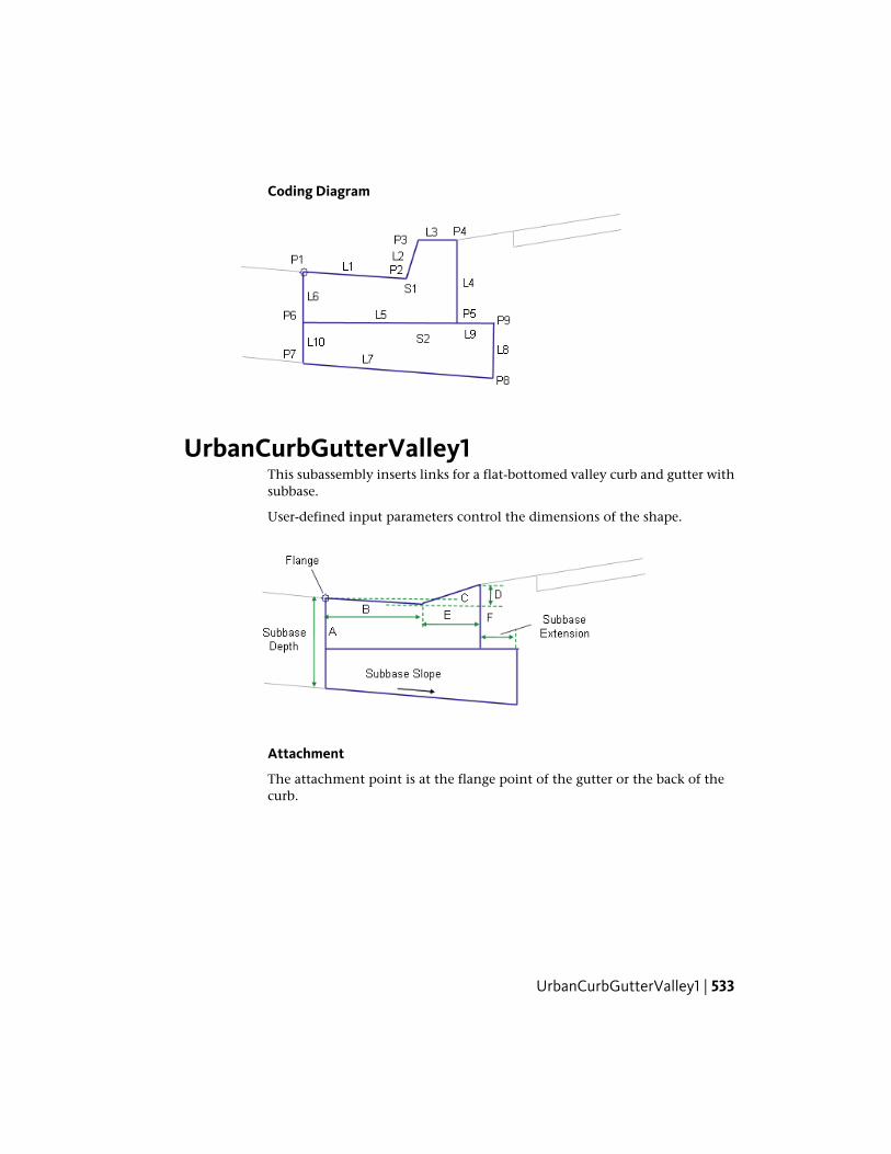
Coding Diagram
UrbanCurbGutterValley1This subassembly inserts links for a flat-bottomed valley curb and gutter withsubbase.
User-defined input parameters control the dimensions of the shape.
Attachment
The attachment point is at the flange point of the gutter or the back of thecurb.
UrbanCurbGutterValley1 | 533

Input ParametersNote: Subbase dimensions are in meters or feet. Curb-and-gutter dimensionsmust be given in millimeters or inches.
DefaultTypeDescriptionParameter
RightLeft/RightSpecifes to insert the subassembly either on theright or the left side of the attachment point.
Side
Gutter EdgeBooleanSpecifies insertion point of the curb and gutter aseither Gutter Edge or Back of Curb
Insertion Point
Outside lanesupereleva-tion slope
BooleanSpecifies method of gutter slope input as: Useoutside lane superelevation slope; Fixed slope; Usedepth of flow line from flange point.
Gutter SlopeMethod
- 2%NumericSpecifies fixed gutter slopeGutter Slope
0.450 mNumeric, posit-ive
Depth to subbase at the flange point. Use zero ifthere is no subbase.
Subbase Depth1.5 ft
0.3 mNumeric, posit-ive
Distance the subbase is extended beyond theback-of-curb. Use zero to terminate the subbaseat the back-of-curb
Subbase Exten-sion 1 ft
Use outsidelane superel-evation
BooleanSelect for subbase to use outside lane supereleva-tion, or to specify a numeric % slope
Use SE
-2 (%)Numeric% slope of the subbase layer. Not used if Use SEis set to True.
Subbase %Slope
175 mmNumeric, posit-ive,
Depth of the gutter at the flange pointDimension A7 in
non-zero
375 mmNumeric, posit-ive,
Width from the gutter flange point to the gutterflowline
Dimension B15 in
non-zero
25 mmNumeric, posit-ive,
Depth from the gutter flange point to the gutterflowline
Dimension C1 in
non-zero
534 | Chapter 3 Subassembly Reference (continued)

DefaultTypeDescriptionParameter
75 mmNumeric, posit-ive,
Height from the gutter flowline to the top-of-curbDimension D3 in
non-zero
250 mmNumeric, posit-ive,
Width from the gutter flowline to the top-of-curbDimension E9 in
non-zero
250 mmNumeric, posit-ive,
Height of the back-of-curbDimension F9 in
non-zero
Behavior
The curb and gutter links are inserted based on the Input Parameter dimensionsDimension A – Dimension F. All dimensions must be positive, non-zero values.If a non-zero subbase depth is given, the subbase layer is inserted to the backof curb, and continues for the Subbase Extension width. The subbase layercloses to the bottom-back-of-curb, as shown in the diagram.
The subassembly builds the shape for a simple curb and gutter, with theattachment point either at (a) inside edge of the gutter (or lip), or (b) the backof the curb. The face of the curb is given a small, constant width to make itnon-vertical.
Target Parameters
This section lists the parameters in this subassembly that can be mapped toone or more target objects, such as a surface, alignment, or profile object ina drawing. For more information, see Setting Targets in the AutoCAD Civil3D User’s Guide Help.
Target Parameters: None.
Output Parameters
None.
Layout Mode Operation
In layout mode, this subassembly displays the curb-and-gutter componentbased on the input parameters given. If the Use SE parameter is set to true,the subbase layer is inserted at a slope of -2%.
UrbanCurbGutterValley1 | 535
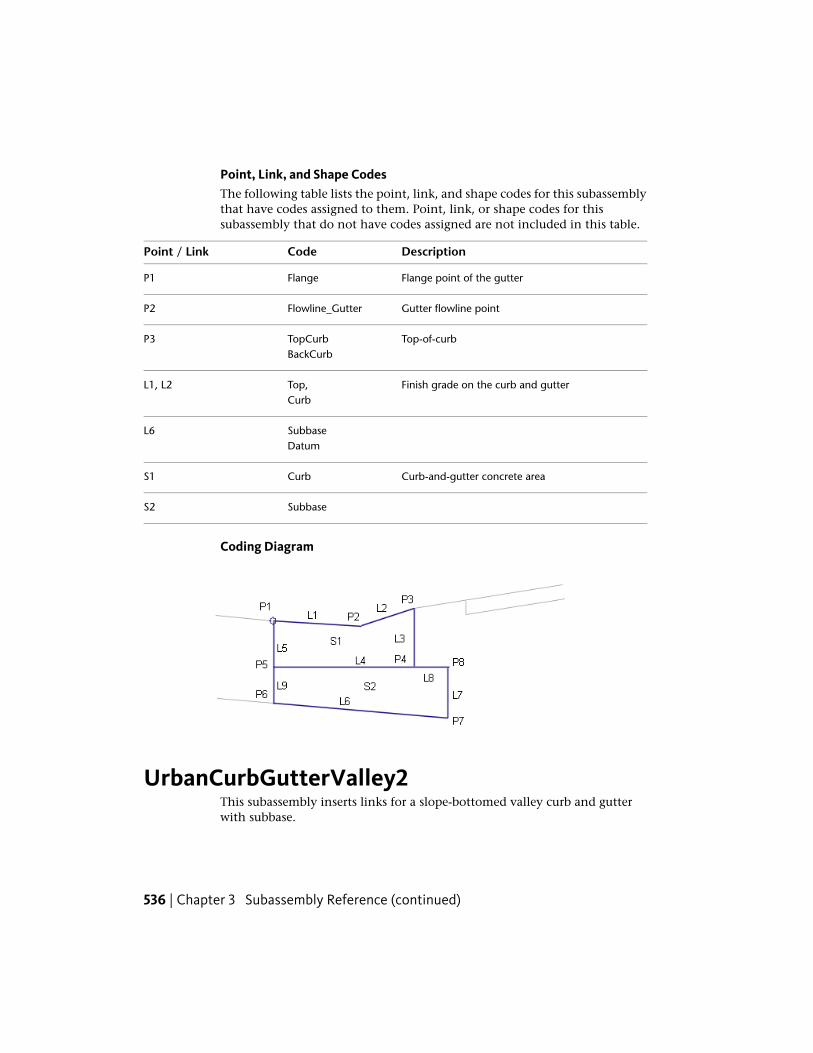
Point, Link, and Shape CodesThe following table lists the point, link, and shape codes for this subassemblythat have codes assigned to them. Point, link, or shape codes for thissubassembly that do not have codes assigned are not included in this table.
DescriptionCodePoint / Link
Flange point of the gutterFlangeP1
Gutter flowline pointFlowline_GutterP2
Top-of-curbTopCurbP3BackCurb
Finish grade on the curb and gutterTop,L1, L2Curb
SubbaseL6Datum
Curb-and-gutter concrete areaCurbS1
SubbaseS2
Coding Diagram
UrbanCurbGutterValley2This subassembly inserts links for a slope-bottomed valley curb and gutterwith subbase.
536 | Chapter 3 Subassembly Reference (continued)
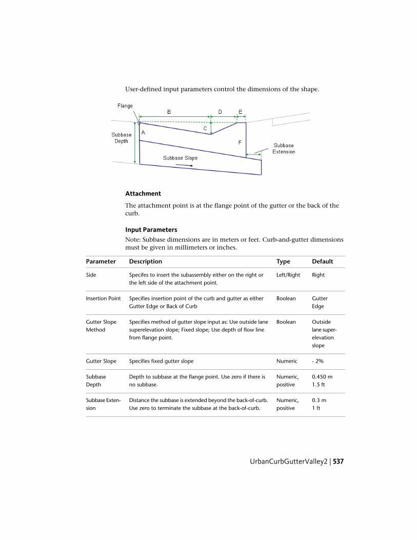
User-defined input parameters control the dimensions of the shape.
Attachment
The attachment point is at the flange point of the gutter or the back of thecurb.
Input ParametersNote: Subbase dimensions are in meters or feet. Curb-and-gutter dimensionsmust be given in millimeters or inches.
DefaultTypeDescriptionParameter
RightLeft/RightSpecifes to insert the subassembly either on the right orthe left side of the attachment point.
Side
GutterEdge
BooleanSpecifies insertion point of the curb and gutter as eitherGutter Edge or Back of Curb
Insertion Point
Outsidelane super-
BooleanSpecifies method of gutter slope input as: Use outside lanesuperelevation slope; Fixed slope; Use depth of flow linefrom flange point.
Gutter SlopeMethod
elevationslope
- 2%NumericSpecifies fixed gutter slopeGutter Slope
0.450 mNumeric,positive
Depth to subbase at the flange point. Use zero if there isno subbase.
SubbaseDepth 1.5 ft
0.3 mNumeric,positive
Distance the subbase is extended beyond the back-of-curb.Use zero to terminate the subbase at the back-of-curb.
Subbase Exten-sion 1 ft
UrbanCurbGutterValley2 | 537

DefaultTypeDescriptionParameter
Use out-side lane
BooleanSelect for subbase to use outside lane superelevation, or tospecify a numeric % slope
Use SE
supereleva-tion
-2 (%)Numeric% slope of the subbase layer. Not used if Use SE is set toTrue.
Subbase%Slope
150 mmNumeric,positive,
Depth of the gutter at the flange pointDimension A6 in
non-zero
610 mmNumeric,positive,
Width from the gutter flange point to the gutter flowlineDimension B24 in
non-zero
100 mmNumeric,positive,
Depth from the gutter flange point to the gutter flowline,and from the gutter flowline to the top-of-curb
Dimension C4 in
non-zero
225 mmNumeric,positive,
Width from the gutter flowline to the top-of-curbDimension D9 in
non-zero
75 mmNumeric,positive,
Width from the top-of-curb to back-of-curbDimension E3 in
non-zero
300 mmNumeric,positive,
Height of the back-of-curbDimension F12 in
non-zero
Behavior
The curb and gutter links are inserted based on the Input Parameter dimensionsDimension A – Dimension F. All dimensions must be positive, non-zero values.If a non-zero subbase depth is given, the subbase layer is inserted to the backof curb, and continues for the Subbase Extension width. The subbase layercloses to the bottom-back-of-curb, as shown in the diagram.
The subassembly builds the shape for a simple curb and gutter, with theattachment point either at (a) inside edge of the gutter (or lip), or (b) the back
538 | Chapter 3 Subassembly Reference (continued)

of the curb. The face of the curb is given a small, constant width to make itnon-vertical.
Target Parameters
This section lists the parameters in this subassembly that can be mapped toone or more target objects, such as a surface, alignment, or profile object ina drawing. For more information, see Setting Targets in the AutoCAD Civil3D User’s Guide Help.
Target Parameters: None.
Output Parameters
None.
Layout Mode Operation
In layout mode, this subassembly displays the curb-and-gutter componentbased on the input parameters given. If the Use SE parameter is set to true,the subbase layer is inserted at a slope of -2%.
Point, Link, and Shape CodesThe following table lists the point, link, and shape codes for this subassemblythat have codes assigned to them. Point, link, or shape codes for thissubassembly that do not have codes assigned are not included in this table.
DescriptionCodePoint / Link
Flange point of the gutterFlangeP1
Gutter flowline pointFlowline_GutterP2
Top-of-curbTopCurbP3
Back-of-curbBackCurbP4
Finish grade on the curb and gutterTop,L1 – L3Curb
SubbaseL7Datum
Curb-and-gutter concrete areaCurbS1
UrbanCurbGutterValley2 | 539

DescriptionCodePoint / Link
SubbaseS2
Coding Diagram
UrbanCurbGutterValley3This subassembly inserts links for a slope-bottomed valley curb and gutterwith subbase.
The bottom surface of the curve flattens to a horizontal link at the gutterflowline. User-defined input parameters control the dimensions of the shape.
Attachment
The attachment point is at the flange point of the gutter or the back of thecurb.
540 | Chapter 3 Subassembly Reference (continued)

Input ParametersNote: Subbase dimensions are in meters or feet. Curb-and-gutter dimensionsmust be given in millimeters or inches.
DefaultTypeDescriptionParameter
RightLeft/RightSpecifes to insert the subassembly either on the right orthe left side of the attachment point.
Side
GutterEdge
BooleanSpecifies insertion point of the curb and gutter as eitherGutter Edge or Back of Curb
Insertion Point
Outsidelane super-
BooleanSpecifies method of gutter slope input as: Use outsidelane superelevation slope; Fixed slope; Use depth of flowline from flange point.
Gutter SlopeMethod
elevationslope
- 2%NumericSpecifies fixed gutter slopeGutter Slope
1.0 mNumeric,positive
Depth to subbase at the flange point. Use zero if there isno subbase.
Subbase Depth1.5 ft
0.3 mNumeric,positive
Distance the subbase is extended beyond the back-of-curb. Use zero to terminate the subbase at the back-of-curb.
Subbase Exten-sion 1 ft
Use Out-side Lane
Selection listSelects whether to use the Outside Lane superelevationslope for the subbase layer, or to set a numeric % slopevalue
Use SE
Supereleva-tion
- 2 (%)NumericCross slope of the subbase layer. Not used if Use SE is setto True.
Subbase Slope
150 mmNumeric,positive,
Depth of the gutter at the flange pointDimension A6 in
non-zero
600 mmNumeric,positive,
Width from the gutter flange point to the gutter flowlineDimension B24 in
non-zero
UrbanCurbGutterValley3 | 541

DefaultTypeDescriptionParameter
50 mmNumeric,positive,
Depth from the gutter flange point to the gutter flowline,and from the gutter flowline to the top-of-curb
Dimension C2 in
non-zero
40 mmNumeric,positive,
Width from the gutter flowline to the top-of-curbDimension D1.5 in
non-zero
150 mmNumeric,positive,
Width from the top-of-curb to back-of-curbDimension E6 in
non-zero
300 mmNumeric,positive,
Height of the back-of-curbDimension F12 in
non-zero
Behavior
The curb and gutter links are inserted based on the Input Parameter valuesfor Dimension A – Dimension F. All dimensions must be positive, non-zerovalues. If a non-zero subbase depth is given, the subbase layer is inserted tothe back of curb, and continues for the Subbase Extension width. The subbaselayer closes to the bottom-back-of-curb, as shown in the diagram.
The subassembly builds the shape for a simple curb and gutter, with theattachment point either at (a) inside edge of the gutter (or lip), or (b) the backof the curb. The face of the curb is given a small, constant width to make itnon-vertical.
Target Parameters
This section lists the parameters in this subassembly that can be mapped toone or more target objects, such as a surface, alignment, or profile object ina drawing. For more information, see Setting Targets in the AutoCAD Civil3D User’s Guide Help.
Target Parameters: None.
Layout Mode Operation
In layout mode, this subassembly displays the curb-and-gutter componentbased on the input parameters given. If a numeric value is given for the Subbase
542 | Chapter 3 Subassembly Reference (continued)
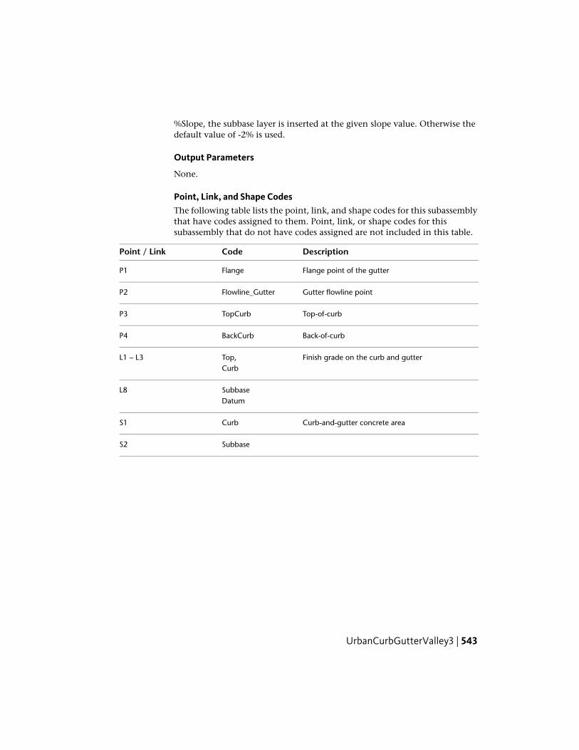
%Slope, the subbase layer is inserted at the given slope value. Otherwise thedefault value of -2% is used.
Output Parameters
None.
Point, Link, and Shape CodesThe following table lists the point, link, and shape codes for this subassemblythat have codes assigned to them. Point, link, or shape codes for thissubassembly that do not have codes assigned are not included in this table.
DescriptionCodePoint / Link
Flange point of the gutterFlangeP1
Gutter flowline pointFlowline_GutterP2
Top-of-curbTopCurbP3
Back-of-curbBackCurbP4
Finish grade on the curb and gutterTop,L1 – L3Curb
SubbaseL8Datum
Curb-and-gutter concrete areaCurbS1
SubbaseS2
UrbanCurbGutterValley3 | 543

Coding Diagram
UrbanReplaceCurbGutter1This subassembly is used to replace an existing curb and gutter, with the sodstrip tying to the existing inside edge of sidewalk. The vertical placement ofcurb and gutter is determined by allowable milling and/or overlay at the flangepoints and by allowable ranges of slopes for sod strip.
To apply this subassembly, flange point information (alignment or offsetvalue) is essential.
544 | Chapter 3 Subassembly Reference (continued)

Attachment
The attachment point is outside/highside point of the sod strip edge of thesidewalk. Though notionally this attachment point is to mark the highsideof the sodstrip, actual location of sod strip high point could vary from this asthe user attaches an appropriate marked point or alignment and profile.Therefore, this attachment point is more of layout time assistance rather thandesign point control.
Input ParametersNote: All dimensions are in meters or feet unless otherwise noted. All slopesare in run over rise form (for example, 4 : 1) unless indicated as a percent slopewith a "%" sign.
DefaultTypeDescriptionParameter
RightLeft/RightSpecifes to insert the subassembly either on theright or the left side of the attachment point.
Side
3.6 mNumericPoint defining the offset of the face of the flangeof the gutter. This offset is as neasured from thebaseline point.
Flange Point Off-set from CL 10 ft
NoneStringThis inside sidewalk point will be used as the highpoint of sod strip. (OPTIONAL)
Sidewalk Point
0.05 mNumeric, posit-ive
Maximum allowable depth of the flange pointbelow the edge of existing pavement.
Max Milling2.5 in
0.08m3.5 in
Numeric, posit-ive
Desirable difference in elevation from the edge ofexisting pavement to the flange point. A positive
Desirable Lift
UrbanReplaceCurbGutter1 | 545

DefaultTypeDescriptionParameter
value is for the flange point being above the exist-ing pavement.
0.02Minimum allowable slope from the back of curbto the sidewalk point.
Min Sod Slope
0.06Maximum allowable slope from the back of curbto the sidewalk point.
Max Sod Slope
NoneStringMark Flange Point - name of a marked point tobe stored at the flange point - for later rehabsubassemblies.
Mark InsidePoint
The following are the same parameters as Curb-AndGutterGeneral subassembly.
0.450 mNumeric, posit-ive
Depth to subbase at the flange point. Use zero ifthere is no subbase.
Subbase Depth1.5 ft
0.3 mNumeric, posit-ive
Distance the subbase is extended beyond theback-of-curb. Use zero to terminate the subbaseat the back-of-curb.
Subbase Exten-sion 1 ft
Use superel-evation
Selection listSelects whether to use the Outside Lane superel-evation slope for the subbase layer, or to set anumeric % slope value
Use SE
-2 (%)Numeric% slope of the subbase layer. Not used if Use SEis set to True.
Subbase %Slope
175 mmNumeric, posit-ive,
Depth of the gutter at the flange point.Dimension A(mm/in) 6 in
non-zero
400 mmWidth from the flange point to the gutter flowline.Dimension B16 in(mm/in)
25 mmNumeric, posit-ive,
Depth from the flange point to the gutter flowline.Dimension C(mm/in) 1 in
non-zero
546 | Chapter 3 Subassembly Reference (continued)

DefaultTypeDescriptionParameter
150 mmNumeric, posit-ive,
Height of curb from the gutter flowline to the top-of-curb.
Dimension D(mm/in) 6 in
non-zero
200 mmNumeric, posit-ive,
Width from the gutter flowline to the back-of-curb.Dimension E(mm/in) 8 in
non-zero
150 mmNumeric, posit-ive,
Width of the top-of-curb.Dimension F(mm/in) 6 in
non-zero
325 mmNumeric, posit-ive,
Height of the back-of-curb.Dimension G(mm/in) 13 in
non-zero
Target ParametersThis section lists the parameters in this subassembly that can be mapped toone or more target objects, such as a surface, alignment, or profile object ina drawing. For more information, see Setting Targets in the AutoCAD Civil3D User’s Guide Help.
StatusDescriptionParameter
OptionalThis will set the offset value for the highside point forsod strip. The following object types can be used as
Inside Edge of Sidewalk
targets for specifying this offset: alignments, polylines,features lines, or survey figures.
OptionalThis will establish the offset value of flange point tostart the subassembly. The following object types can
Flange Point
be used as targets for specifying this offset: align-ments, polylines, features lines, or survey figures.
OptionalThis will set the offset value for the highside point forsod strip. The following object types can be used as
Inside Edge of SidewalkProfile
targets for specifying this elevation: profiles, 3Dpolylines, feature lines, or survey figures.
RequiredName of the existing surface, used to determine theedge of pavement elevation at the flange point, and
EGTopSurf
UrbanReplaceCurbGutter1 | 547

StatusDescriptionParameter
is also used to determine the elevation of the SidewalkPoint if given as an offset or alignment; but profilesnot set. The following object types can be used astargets for specifying this surfaces: surfaces.
If marked points are provided, target parameters are unnecessary and will beignored even if set. If marked points are not set and offsets or alignments areused to locate points, it is expected to set profiles through target parameters.If they are not, this subassembly takes its elevation from the surface set in thetarget parameter listed above.
Output Parameters
DefaultTypeDescriptionParameter
NumericCross slope of designed sod stripSod Strip Slope
Numeric, posit-ive
Gutter slope in the new curb and gutter sub-assembly
Gutter Slope
Behavior
This subassembly is used to place a new curb and gutter parametrically, andcan optionally tie (with a sod strip) into either the inside edge of the existingsidewalk, or to a new sidewalk created with another subasembly. The horizontalplacement of the curb and gutter is determined from the previously knownflange point location. Highside of the sod strip can be located either by a fixedoffset or any other marked point, such as the inside edge of sidewalk.Alternatively, this point can come from target parameters of an aligment andprofile. Newly designed flange point, optionally marked so that it can be usedas input later for replacement lane subassemblies.
Key steps in completing this conditional subassembly are as follows:
1 Get existing pavement elevation at the flange point offset.
2 Set flange point elevation based on the minimum lift value.
3 Next insert curb and gutter points from P to P4 using the input parameters(similar to CurbAndGutterGeneral).
4 If the inside sidewalk marked point is assigned, establish that point asP10. If marked point is not associated, look for target parameters for
548 | Chapter 3 Subassembly Reference (continued)
'inside edge of sidewalk" alignment. If yes, then get profile elevation fromthe surface target parameter.
5 If none of the above data is available for the highside of the sod strip,use the offset as dictated by attachment point to establish point P10.
6 Find the slope between P4 and P10.
7 Check whether that slope is within the parameters of Min/Max sod stripslopes.
8 If it is lower than minimum, set the slope to minimum allowable andcomputed points P4 to P1 backwards. Similarly, if the slope is more thanmaximum allowable sod strip slopes, set it to maximum allowable andcalculate P4 to P1.
9 Check whether the elevation difference between P1 and P11 is withintolerable limits of max milling. If P is below P11 and difference is morethan max milling, then abort, resulting in an error displayed in the eventviewer.
All other curb and gutter links are inserted, based on the Input Parameterdimensions Dimension A - Dimension F. All dimensions must be positive,non-zero values. If a non-zero subbase depth is given, the subbase layer isinserted to the back of curb, and continues for the Subbase Extension width.The subbase layer closes to the bottom-back-of-curb as shown in the diagram.
Layout Mode Operation
In layout mode , this subassembly is set based on the attachment point andthe default flange point offset from baseline. The width of the sod strip iscomputed by subtracting the curb and gutter total widt from "flange point toattacment point" distance. The minimum allowable sod strip slope is used tocalculate the back of curb point from which the rest of the curb and gutter isdrawn, using the input parameters given.
Point, Link, and Shape CodesThe following table lists the point, link, and shape codes for this subassemblythat have codes assigned to them. Point, link, or shape codes for thissubassembly that do not have codes assigned are not included in this table.
DescriptionCodePoint / Link
Flange point of the gutterFlangeP1
UrbanReplaceCurbGutter1 | 549

DescriptionCodePoint / Link
Gutter flowline pointFlowline_GutterP2
Top-of-curbTopCurbP3
Back-of-curbBackCurbP4
All curb linksCurbL1–L6
Finish grade on the curb and gutterTopL1–L3
SubbaseL7Datum
DatumL4, L8, L9
Top, Datum, SodL11
Curb-and-gutter concrete areaCurbS1
SubbaseS2
Coding Diagram
UrbanReplaceCurbGutter2This subassembly is used to replace an existing curb and gutter, with the sodstrip tying to the existing inside edge of sidewalk. The vertical placement ofthe curb and gutter is controlled by a design profile of the back of curb.
550 | Chapter 3 Subassembly Reference (continued)

To apply this subassembly, flange point information (alignment or offsetvalue) is essential.
Attachment
The attachment point is outside/highside point of the sod strip edge of thesidewalk. Though notionally this attachment point is to mark the highsideof the sodstrip, actual location of sod strip high point could vary from this asthe user attaches an appropriate marked point or alignment and profile.Therefore, this attachment point is more of layout time assistance rather thandesign point control.
Input ParametersNote: All dimensions are in meters or feet unless otherwise noted. All slopesare in run over rise form (for example, 4 : 1) unless indicated as a percent slopewith a "%" sign.
DefaultTypeDescriptionParameter
RightLeft/RightSpecifes to insert the subassembly either on theright or the left side of the attachment point.
Side
UrbanReplaceCurbGutter2 | 551

DefaultTypeDescriptionParameter
3.6 mNumericPoint defining the offset of the face of the flangeof the gutter. This offset is as measured from the
Flange Point Off-set from CL 10 ft
baseline of the assembly (or corridor in corridorstate).
NoneStringThis inside sidewalk point will be used as the highpoint of sod strip. (OPTIONAL)
Sidewalk Point
NoneStringMark Flange Point - name of a marked point tobe stored at the flange point - for later rehabsubassemblies.
Mark InsidePoint
The following are the same parameters as Curb-AndGutterGeneral subassembly.
0.450 mNumeric, posit-ive
Depth to subbase at the flange point. Use zero ifthere is no subbase.
Subbase Depth1.5 ft
0.3 mNumeric, posit-ive
Distance the subbase is extended beyond theback-of-curb. Use zero to terminate the subbaseat the back-of-curb.
Subbase Exten-sion 1 ft
-2 (%)Numeric% slope of the subbase layer. Not used if Use SEis set to True.
Subbase %Slope
175 mmNumeric, posit-ive,
Depth of the gutter at the flange point.Dimension A(mm/in) 7 in
non-zero
400 mmWidth from the flange point to the gutter flowline.Dimension B16 in(mm/in)
25 mmNumeric, posit-ive,
Depth from the flange point to the gutter flowline.Dimension C(mm/in) 1 in
non-zero
150 mmNumeric, posit-ive,
Height of curb from the gutter flowline to the top-of-curb.
Dimension D(mm/in) 6 in
non-zero
552 | Chapter 3 Subassembly Reference (continued)

DefaultTypeDescriptionParameter
200 mmNumeric, posit-ive,
Width from the gutter flowline to the back-of-curb.Dimension E(mm/in) 8 in
non-zero
150 mmNumeric, posit-ive,
Width of the top-of-curb.Dimension F(mm/in) 6 in
non-zero
325 mmNumeric, posit-ive,
Height of the back-of-curb.Dimension G(mm/in) 13 in
non-zero
Target ParametersThis section lists the parameters in this subassembly that can be mapped toone or more target objects, such as a surface, alignment, or profile object ina drawing. For more information, see Setting Targets in the AutoCAD Civil3D User’s Guide Help.
StatusDescriptionParameter
OptionalThis will set offset value for the highside point for sodstrip. The following object types can be used as tar-
Inside Edge of Sidewalk
gets for specifying this offset: alignments, polylines,features lines, or survey figures.
OptionalThis will establish offfest of flange point to start thesubassembly. The following object types can be used
Flange Point
as targets for specifying this offset: alignments, poly-lines, features lines, or survey figures.
RequiredThis helps position curb and gutter. The followingobject types can be used as targets for specifying this
Back of Curb Profile
elevation: profiles, 3D polylines, feature lines, or sur-vey figures.
OptionalThis will set offset value for the highside point for sodstrip. The following object types can be used as tar-
Inside Edge of Sidewalk
gets for specifying this elevation: profiles, 3D poly-lines, feature lines, or survey figures.
UrbanReplaceCurbGutter2 | 553

StatusDescriptionParameter
RequiredName of the existing surface, used to determine theedge of pavement elevation at the flange point, and
EGTopSurf
is also used to determine the elevation of the SidewalkPoint if given as an offset or alignment; but profilesnot set. The following object types can be used astargets for specifying this surfaces: surfaces.
If marked points are provided, target parameters are unnecessary and will beignored even if set. If marked points are not set, and offsets or alignments areused to locate points, it is expected to set profiles through target parameters.If they are not, this subassembly takes its elevation from the surface that isset in the target parameters described above.
If Back of Curb profile is not assigned in corridor definition, then thesubassembly aborts with an error message in event viewer.
Output Parameters
DefaultTypeDescriptionParameter
NumericCross slope of designed sod stripSod Strip Slope
Numeric, posit-ive
Gutter slope in the new curb and gutter sub-assembly
Gutter Slope
Behavior
This subassembly is used to place a new curb and gutter parametrically, andcan optionally tie (with a sod strip) into either the inside edge of the existingsidewalk, or to a new sidewalk created with another subasembly. The horizontalplacement of the curb and gutter is determined from the previously knowflange point location. Highside of the sod strip can be located either by a fixedoffset or any other marked point, such as inside edge of sidewalk. Alternativelythis point can come from the target parameter of an aligment and profile.Newly designed flange point, optionally marked so that it can be used as inputlater for replacement lane subassemblies.
Key steps in completing this conditional subassembly are as follows:
1 From flange point offset and the input parameters locate the offset of“back of curb”.
554 | Chapter 3 Subassembly Reference (continued)

2 From the target parameter, get the "back of curb" elevation at that stationand establish this point P4.
3 From this point establish all curb and gutter points and links using theinput parameters (similar to UrbanCurbGutterGeneral1
4 If inside sidewalk marked point is assigned, establish that point as P10.If marked point is not associated, look for target parameters for 'insideedge of sidewalk" alignment. If yes then get profile elevation or from thesurface target parameter.
5 If none of the above data is available for the highside of the sod strip,use the offset as dictated by attachment point to establish point P10.
All other curb and gutter links are inserted based on the Input Parameterdimensions Dimension A - Dimension F. All dimensions must be positive,non-zero values. If a non-zero subbase depth is given, the subbase layer isinserted to the back of curb, and continues for the Subbase Extension width.The subbase layer closes to the bottom-back-of-curb as shown in the diagram.
Layout Mode Operation
In layout mode the subassembly is set based on the attachment point and thedefault flange point offset from baseline. Width of the sod strip is computedby subtracting the curb and gutter total width from "flange point to attachmentpoint" distance. Use 2% slope to calculate the low side of sod strip (or back ofcurb point), from which the rest of curb and gutter is drawn using the inputparameters given.
Point, Link, and Shape CodesThe following table lists the point, link, and shape codes for this subassemblythat have codes assigned to them. Point, link, or shape codes for thissubassembly that do not have codes assigned are not included in this table.
DescriptionCodePoint / Link
Flange point of the gutterFlangeP1
Gutter flowline pointFlowline_GutterP2
Top-of-curbTopCurbP3
Back-of-curbBackCurbP4
All curb linksCurbL1–L6
UrbanReplaceCurbGutter2 | 555
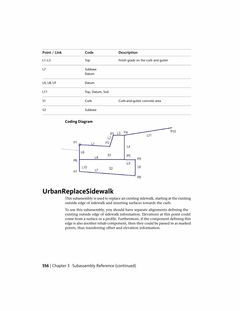
DescriptionCodePoint / Link
Finish grade on the curb and gutterTopL1–L3
SubbaseL7Datum
DatumL4, L8, L9
Top, Datum, SodL11
Curb-and-gutter concrete areaCurbS1
SubbaseS2
Coding Diagram
UrbanReplaceSidewalkThis subassembly is used to replace an existing sidewalk, starting at the existingoutside edge of sidewalk and inserting surfaces towards the curb.
To use this subassembly, you should have separate alignments defining theexisting outside edge of sidewalk information. Elevations at this point couldcome from a surface or a profile. Furthermore, if the component defining thisedge is also another rehab component, then they could be passed in as markedpoints, thus transferring offset and elevation information.
556 | Chapter 3 Subassembly Reference (continued)

Attachment
The attachment point is (near) the outside edge of the sidewalk. For betterresults, insert this on a controlling offset (with fixed offset) marker pointduring assembly construction.
Input ParametersNote: All dimensions are in meters or feet unless otherwise noted. All slopesare in run-over-rise form (for example, 4 : 1) unless indicated as a percentslope with a “%” sign.
DefaultTypeDescriptionParameter
RightLeft/RightSpecifes to insert the subassembly either on theright or the left side of the attachment point.
Side
NoneStringTo define outside edge of sidewalk and elevationto start the subassembly (OPTIONAL)
Outside SidewalkMarked Point
1.5mNumericWidth of the sidewalk, measuring inwards fromhigh edge of sidewalk point
Width5.0ft
-2%NumericCross slope of sidewalk in %, measuring inwardsfrom high edge of sidewalk
% Slope
Numeric,positive
Depth or thickness of the sidewalkDepth
NoneStringName of the marked point to be stored at the newlow edge of sidewalk (OPTIONAL)
Mark Inside Point
UrbanReplaceSidewalk | 557

Target ParametersThis section lists the parameters in this subassembly that can be mapped toone or more target objects, such as a surface, alignment, or profile object ina drawing. For more information, see Setting Targets in the AutoCAD Civil3D User’s Guide Help.
StatusDescriptionParameter
OptionalThis will set the outside edge of proposed sidewalk asstart point. The following object types can be used as
Outside Edge of Side-walk
targets for specifying this offset: alignments, polylines,features lines, or survey figures.
OptionalThis will set the outside edge elevation value of pro-posed sidewalk. The following object types can be used
Left Gutter Profile
as targets for specifying this elevation: profiles, 3Dpolylines, feature lines, or survey figures.
RequiredIf profiles are not supplied for left/right edge of pave-ment elevations, then this surface elevation at that
EGTopSurf
offset will be picked up as elevation value. The follow-ing object types can be used as targets for specifyingthis surfaces: surfaces.
Output Parameters
DefaultTypeDescriptionParameter
-2%NumericCross slope of sidewalk in %, measuring inwardsfrom high edge of sidewalk
% Slope
Numeric,positive
Depth or thickness of the sidewalkDepth
Behavior
By default outside edge of sidewalk is located at the attached marked point orat the associated alignment. Similraly elevation is set based on marker pointassociated, or profile or from the surface at that offset.
Once this start point is established,sidewalk structure links are inserted inwardsfrom this point for given width, slope, and depth. If a name is given for MarkInside Point, a marked point is stored at the new low edge of sidwalk.
558 | Chapter 3 Subassembly Reference (continued)

Layout Mode Operation
In layout mode, this subassembly starts at the attached point and draws asingle shape with given dimensions, such as width, slope and depth.
NOTE While constructing an assembly, it is recommended that this subassemblybe added at a controlling offset, if there is no previously marked point. Thiscontrolling offset could be at a decent offset from the baseline marker, so that thelayout mode looks like a typical section. However, it is recommended that the userdoesn't have to map this controlling offset to any "alignment/profile" in the corridorstate, as that would cause problems such as making the design not perpendicularto the baseline in some cases. Not associating this controlling offset will not haveany effect on the corridor, as the start point is attached to an alignment/markedpoint through the subassembly macro for an exact location.
Point, Link, and Shape Codes
DescriptionCodePoint / Link
Inside edge of sidewalk on finish gradeSidewalk_InP1
Outside edge of sidewalk on finish gradeSidewalk_OutP2
Top SidewalkL1
DatumL2
Sidewalk concrete areaSidewalkS1
Coding Diagram
UrbanReplaceSidewalk | 559

UrbanSidewalkThis subassembly inserts links for a concrete sidewalk with inside and outsidegrass boulevards.
Attachment
The attachment point is at the inside edge of the inside boulevard. TheUrbanSidewalk subassembly is typically attached to a back-of-curb or edge ofpavement.
Input ParametersNote: All dimensions are in meters or feet unless otherwise noted. All slopesare in run-over-rise form (for example, 4 : 1) unless indicated as a percentslope with a “%” sign.
DefaultTypeDescriptionParameter
RightLeft/RightSpecifes to insert the subassembly either on theright or the left side of the attachment point.
Side
0.0Numeric,positive
Width of the inside grass boulevardInside BoulevardWidth
1.5 mNumeric,positive,
Width of the concrete sidewalkSidewalk Width5.0 ft
non-zero
0.0Numeric,positive
Width of the outside grass boulevardOutsideBoulevard Width
2 (%)Numeric% slope of the sidewalk and grass strips. Positiveslopes are upwards from the attachment point.
%Slope
560 | Chapter 3 Subassembly Reference (continued)

DefaultTypeDescriptionParameter
0.100 mNumeric,positive
Depth of concrete for the sidewalkDepth0.333 ft
Behavior
The inside grass strip, sidewalk, and outside grass boulevard links are insertedoutward from the attachment point at the given slope. The grass strips canbe omitted by specifying a zero-width.
Optionally, various element widths can be attained by attaching to offsetalignments. Also, the sidewalk cross slope can be derived by tying into anoffset profile.
Target ParametersThis section lists the parameters in this subassembly that can be mapped toone or more target objects, such as a surface, alignment, or profile object ina drawing. For more information, see Setting Targets in the AutoCAD Civil3D User’s Guide Help.
StatusType of AssignmentParameter
OptionalMay be used to override the fixed Inside BoulevardWidth and tie the inside edge-of-sidewalk to an offset
Inside BoulevardWidth
alignment. The following object types can be used astargets for specifying this offset: alignments, polylines,features lines, or survey figures.
OptionalMay be used to override the fixed Width of Sidewalkand tie the outside edge-of-sidwalk to an offset align-
Sidewalk Width
ment. The following object types can be used as targetsfor specifying this offset: alignments, polylines, featureslines, or survey figures.
OptionalMay be used to override the fixed Outside BoulevardWidth with an offset alignment. The following object
Outside BoulevardWidth
types can be used as targets for specifying this offset:alignments, polylines, features lines, or survey figures.
Output Parameters
None.
UrbanSidewalk | 561
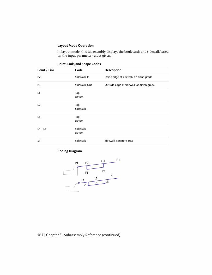
Layout Mode Operation
In layout mode, this subassembly displays the boulevards and sidewalk basedon the input parameter values given.
Point, Link, and Shape Codes
DescriptionCodePoint / Link
Inside edge of sidewalk on finish gradeSidewalk_InP2
Outside edge of sidewalk on finish gradeSidewalk_OutP3
TopL1Datum
TopL2Sidewalk
TopL3Datum
SidewalkL4 – L6Datum
Sidewalk concrete areaSidewalkS1
Coding Diagram
562 | Chapter 3 Subassembly Reference (continued)
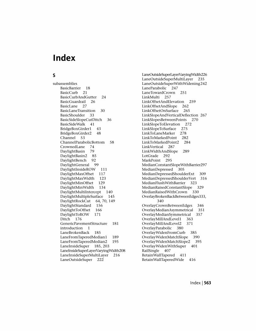
Index
S
subassembliesBasicBarrier 18BasicCurb 21BasicCurbAndGutter 24BasicGuardrail 26BasicLane 27BasicLaneTransition 30BasicShoulder 33BasicSideSlopeCutDitch 36BasicSideWalk 41BridgeBoxGirder1 43BridgeBoxGirder2 48Channel 53ChannelParabolicBottom 58CrownedLane 74DaylightBasin 79DaylightBasin2 85DaylightBench 92DaylightGeneral 99DaylightInsideROW 111DaylightMaxOffset 117DaylightMaxWidth 123DaylightMinOffset 129DaylightMinWidth 134DaylightMultiIntercept 140DaylightMultipleSurface 145DaylightRockCut 64, 70, 149DaylightStandard 156DaylightToOffset 166DaylightToROW 171Ditch 176GenericPavementStructure 181introduction 1LaneBrokenBack 185LaneFromTaperedMedian1 189LaneFromTaperedMedian2 195LaneInsideSuper 185, 203LaneInsideSuperLayerVaryingWidth208LaneInsideSuperMultiLayer 216LaneOutsideSuper 222
LaneOutsideSuperLayerVaryingWidth226LaneOutsideSuperMultiLayer 235LaneOutsideSuperWithWidening242LaneParabolic 247LaneTowardCrown 251LinkMulti 257LinkOffsetAndElevation 259LinkOffsetAndSlope 262LinkOffsetOnSurface 265LinkSlopeAndVerticalDeflection 267LinkSlopesBetweenPoints 270LinkSlopeToElevation 272LinkSlopeToSurface 275LinkToLaneMarker 278LinkToMarkedPoint 282LinkToMarkedPoint2 284LinkVertical 287LinkWidthAndSlope 289LotGrade 292MarkPoint 295MedianConstantSlopeWithBarrier297MedianDepressed 305MedianDepressedShoulderExt 309MedianDepressedShoulderVert 316MedianFlushWithBarrier 323MedianRaisedConstantSlope 329MedianRaisedWithCrown 330OverlayBrokenBackBetweenEdges333,
340OverlayCrownBetweenEdges 346OverlayMedianAsymmetrical 351OverlayMedianSymmetrical 357OverlayMillAndLevel1 363OverlayMillAndLevel2 371OverlayParabolic 380OverlayWidenFromCurb 385OverlayWidenMatchSlope 390OverlayWidenMatchSlope2 395OverlayWidenWithSuper 401RailSingle 407RetainWallTapered 411RetainWallTaperedWide 416
Index | 563

RetainWallTieToDitch 420RetainWallToLowSide 426RetainWallVertical 430ShapeTrapezoidal 435ShoulderExtendAll 439, 476, 483ShoulderExtendSubbase 444ShoulderMultiLayer 450ShoulderMultiLayerVaryingWidth456ShoulderMultiSurface 461ShoulderVerticalSubbase 467ShoulderWidening 471SideDitch 490SideDitchUShape 493SideDitchWithLid 497SimpleNoiseBarrier 502
StrippingPavement 507StrippingTopSoil 511TrenchPipe1 513TrenchPipe2 517TrenchPipe3 521TrenchWithPipe 526UrbanCurbGutterGeneral 529UrbanCurbGutterValley1 533UrbanCurbGutterValley2 536UrbanCurbGutterValley3 540UrbanReplaceCurbGutter1 544UrbanReplaceCurbGutter2 550UrbanReplaceSidewalk 556UrbanSidewalk 560
564 | Index