SUB-COMMITTEE ON SHIP DESIGN AND CONSTRUCTION€¦ · 1 The Sub-Committee on Ship Design and...
125
I:\SDC\06\SDC 6-7-Add.2.docx E SUB-COMMITTEE ON SHIP DESIGN AND CONSTRUCTION 6th session Agenda item 7 SDC 6/7/Add.2 21 September 2018 Original: ENGLISH AMENDMENTS TO THE 2011 ESP CODE Consolidated version of the ESP Code (part 3) Submitted by IACS and the Secretariat SUMMARY Executive summary: This document provides part 3 of the report on the development of a draft consolidated text of the ESP Code, including the draft consolidated text of part A of annex B of the Code Strategic direction, if applicable: Other work Output: OW 2 Action to be taken: Paragraph 6 Related documents: SDC 4/16; SDC 5/15, SDC 5/15/Add.1; MSC 99/22; SDC 6/7, SDC 6/7/Add.1 and SDC 6/7/Add.3 Background 1 The Sub-Committee on Ship Design and Construction (SDC), at its fourth session, authorized the IMO Secretariat and IACS to prepare a draft consolidated text of the ESP Code (in track changes showing all amendments to the 2011 ESP Code) for consideration at SDC 6 (SDC 4/16, paragraph 9.5.2). 2 SDC 5 agreed to proceed with the development of the draft consolidated version of the ESP Code, taking into account: .1 corrigenda 1 and 2 to resolution A.1049(27); .2 amendments adopted by resolutions MSC.371(93), MSC.381(94) and Corr.1, MSC.405(96) and MSC.412(97);
Transcript of SUB-COMMITTEE ON SHIP DESIGN AND CONSTRUCTION€¦ · 1 The Sub-Committee on Ship Design and...

I:\SDC\06\SDC 6-7-Add.2.docx
E
SUB-COMMITTEE ON SHIP DESIGN AND CONSTRUCTION 6th session Agenda item 7
SDC 6/7/Add.2
21 September 2018 Original: ENGLISH
AMENDMENTS TO THE 2011 ESP CODE
Consolidated version of the ESP Code (part 3)
Submitted by IACS and the Secretariat
SUMMARY
Executive summary: This document provides part 3 of the report on the development of a draft consolidated text of the ESP Code, including the draft consolidated text of part A of annex B of the Code
Strategic direction,
if applicable:
Other work
Output: OW 2
Action to be taken: Paragraph 6
Related documents: SDC 4/16; SDC 5/15, SDC 5/15/Add.1; MSC 99/22; SDC 6/7, SDC 6/7/Add.1 and SDC 6/7/Add.3
Background 1 The Sub-Committee on Ship Design and Construction (SDC), at its fourth session, authorized the IMO Secretariat and IACS to prepare a draft consolidated text of the ESP Code (in track changes showing all amendments to the 2011 ESP Code) for consideration at SDC 6 (SDC 4/16, paragraph 9.5.2). 2 SDC 5 agreed to proceed with the development of the draft consolidated version of the ESP Code, taking into account:
.1 corrigenda 1 and 2 to resolution A.1049(27); .2 amendments adopted by resolutions MSC.371(93), MSC.381(94) and Corr.1,
MSC.405(96) and MSC.412(97);

SDC 6/7/Add.2 Page 2
I:\SDC\06\SDC 6-7-Add.2.docx
.3 draft amendments aligning the Code with the latest version of IACS UR Z10, proposing editorial changes to identify all mandatory requirements and improving the format of the tables and forms, expected to be approved at MSC 99; and
.4 the outcome of the intersessional review of the existing footnotes.
3 SDC 5 also agreed that the draft consolidated version of the ESP Code should be finalized for consideration at this session, taking into account the related outcome of MSC 100, with a view to:
.1 preparing a draft Assembly resolution for adoption of the draft consolidated version of the ESP Code, revoking resolutions A.744(18) and A.1049(27); and
.2 subsequent submission to MSC 101, for endorsement, and final adoption
at A 31. 4 MSC 99 approved the draft amendments to the 2011 ESP Code, prepared by SDC 5 and requested the Secretary-General to circulate them in accordance with SOLAS article VIII, with a view to adoption at MSC 100. Proposal 5 This part of the report on the development of a draft consolidated text of the ESP Code provides the draft consolidated text of part A of annex B of the Code. Action requested of the Sub-Committee 6 The Sub-Committee is invited to consider the enclosed draft consolidated text of part A of annex B of the Code, taking into account the amendments to be adopted by MSC 100, and take action, as appropriate.
***

SDC 6/7/Add.2 Annex, page 1
I:\SDC\06\SDC 6-7-Add.2.docx
ANNEX DRAFT INTERNATIONAL CODE ON THE ENHANCED PROGRAMME OF INSPECTIONS
DURING SURVEYS OF BULK CARRIERS AND OIL TANKERS, 2011[2019] (2011[2019] ESP CODE)*
ANNEX B
CODE ON THE ENHANCED PROGRAMME OF INSPECTIONS
DURING SURVEYS OF OIL TANKERS
Part A
CODE ON THE ENHANCED PROGRAMME OF INSPECTIONS DURING SURVEYS OF DOUBLE-HULL OIL TANKERS
1 General 1.1 Application18 1.1.1 The Code should is to apply to all self-propelled double-hull oil tankers of 500 gross tonnage and above. 1.1.2 The Code should is to apply to surveys of hull structure and piping systems in way of cargo tanks, pump-rooms, cofferdams, pipe tunnels, void spaces within the cargo area and all ballast tanks. 1.1.3 The Code contains the minimum extent of examination, thickness measurements and tank testing. The survey should is to be extended when substantial corrosion and/or structural defects are found and include additional close-up survey when necessary. * Tracked changes are created using "strikeout" for deleted text and:
.1 "purple shading" to highlight all modifications and new insertions, including deleted text, introduced
by corrigenda 1 and 2 to resolution A.1049(27); .2 "blue shading" to highlight all modifications and new insertions, including deleted text, introduced by
resolution MSC.371(93); .3 "green shading" to highlight all modifications and new insertions, including deleted text, introduced
by resolution MSC.381(94) and Corr.1; .4 "yellow shading" to highlight all modifications and new insertions, including deleted text, introduced
by resolution MSC.405(96); .5 "red shading" to highlight all modifications and new insertions, including deleted text, introduced by
resolution MSC.412(97); .6 "pink shading" to highlight all modifications and new insertions, including deleted text, approved by
MSC 99 (MSC 99/22/Add.2); and .7 "grey shading" to highlight all new modifications and insertions, including deleted text, introduced by
the co-sponsors for consideration at this session.
18 The intention of the Code is to ensure that an appropriate level of review of plans and documents is
conducted and consistency in application is attained. Such evaluation of survey reports, survey programmes, planning documents, etc., should be carried out at the managerial level of the Administration or organization recognized by the Administration.

SDC 6/7/Add.2 Annex, page 2
I:\SDC\06\SDC 6-7-Add.2.docx
1.1.4 The surveys should are to be carried out during the surveys prescribed by regulation I/10 of the Convention. 1.2 Definitions 1.2.1 Double-hull oil tanker is a ship which is constructed primarily for the carriage of oil19 in bulk, which has the cargo tanks protected by a double-hull which extends for the entire length of the cargo area, consisting of double sides and double-bottom spaces for the carriage of water ballast or void spaces. 1.2.2 Ballast tank is a tank which is used solelyprimarily for the carriage of salt water ballast. 1.2.3 Combined cargo/ballast tank, if referred to within the Code, is a tank which is used for the carriage of cargo or ballast water as a routine part of the vessel's operation and will be treated as a Ballast Tank. Cargo tanks in which water ballast might be carried only in exceptional cases per MARPOL regulation I/18.3 are to be treated as cargo tanks. 1.2.4 Overall survey is a survey intended to report on the overall condition of the hull structure and determine the extent of additional close-up surveys. 1.2.5 Close-up survey is a survey where the details of structural components are within the close visual inspection range of the surveyor, i.e. normally within reach of hand. 1.2.6 Transverse section is the cross section of the hull perpendicular to the ship's centreline and includes all longitudinal members such as plating, longitudinals and girders at the deck, sides, bottom, inner bottom and longitudinal bulkheads. For transversely framed oil tankers, a transverse section includes adjacent frames and their end connections in way of transverse sections. 1.2.7 Representative tanks are those which are expected to reflect the condition of other tanks of similar type and service and with similar corrosion prevention systems. When selecting representative tanks, account should is to be taken of the service and repair history on board and identifiable critical structural areas and/or suspect areas. 1.2.8 Suspect areas are locations showing substantial corrosion and/or are considered by the surveyor to be prone to rapid wastage. 1.2.9 Substantial corrosion is an extent of corrosion such that assessment of corrosion pattern indicates a wastage in excess of 75% of allowable margins, but within acceptable limits. For ships built under the IACS Common Structural Rules, substantial corrosion is an extent of corrosion such that the assessment of the corrosion pattern indicates a gauged (or measured) thickness between tnet + 0.5mm and tneta measured thickness between tren + 0.5 mm and tren. Renewal thickness (tren) is the minimum allowable thickness, in mm, below which renewal of structural members is to be carried out. 1.2.10 Corrosion prevention system is normally considered a full hard protective coating. Hard protective coating should is to usually be epoxy coating or equivalent. Other coating systems, which are neither soft nor semi-hard coatings, may be considered acceptable as alternatives provided that they are applied and maintained in compliance with the manufacturer's specification.
19 MARPOL Annex I cargoes. The requirements of these Guidelines are also applicable to existing double-hull
tankers not complying with MARPOL regulation I/19, but having a U-shaped midship section.

SDC 6/7/Add.2 Annex, page 3
I:\SDC\06\SDC 6-7-Add.2.docx
1.2.11 Coating condition is defined as follows:
GOOD condition with only minor spot rusting; FAIR condition with local breakdown of coating at edges of stiffeners and weld
connections and/or light rusting over 20% or more of areas under consideration, but less than as defined for POOR condition; and
POOR condition with general breakdown of coating over 20% or more of areas or
hard scale at 10% or more of areas under consideration. 1.2.12 Critical structural areas are locations which have been identified from calculations to require monitoring or from the service history of the subject ship or from similar or sister ships to be sensitive to cracking, buckling or corrosion which would impair the structural integrity of the ship. 1.2.13 Cargo area is that part of the ship which contains cargo tanks, slop tanks and cargo/ballast pump-rooms, cofferdams, ballast tanks and void spaces adjacent to cargo tanks and also deck areas throughout the entire length and breadth of the part of the ship over the above-mentioned spaces. 1.2.14 Intermediate survey is a survey carried out either at the second or the third annual survey. 1.2.15 Prompt and thorough repair is a permanent repair completed at the time of survey to the satisfaction of the surveyor, therein removing the need for the imposition of any associated condition of classification or recommendation. 1.2.16 Special consideration or specially considered (in connection with close-up surveys and thickness measurements) means sufficient close-up inspection and thickness measurements are taken to confirm the actual average condition of the structure under coating. 1.2.17 Pitting corrosion is defined as scattered corrosion spots/areas with local material reductions which are greater than the general corrosion in the surrounding area. Pitting intensity is defined in figure 1.
1.2.18 Edge corrosion is defined as local material loss at the free edges of plates, stiffeners, primary support members and around openings. An example of edge corrosion is shown in figure 2.
1.2.19 Grooving corrosion is typically local material loss adjacent to weld joints along abutting stiffeners and at stiffener or plate butts or seams. An example of groove corrosion is shown in figure 3.

SDC 6/7/Add.2 Annex, page 4
I:\SDC\06\SDC 6-7-Add.2.docx
Figure 1: Pitting intensity diagrams
Figure 2: Edge corrosion

SDC 6/7/Add.2 Annex, page 5
I:\SDC\06\SDC 6-7-Add.2.docx
Figure 3: Grooving corrosion 1.3 Repairs 1.3.1 Any damage in association with wastage over the allowable limits (including buckling, grooving, detachment or fracture), or extensive areas of wastage over the allowable limits, which affects or, in the opinion of the Administration, will affect the ship's structural, watertight or weathertight integrity, should is to be promptly and thoroughly (see 1.2.15) repaired. Areas to be considered include:
.1 bottom structure and bottom plating; .2 side structure and side plating; .3 deck structure and deck plating; .4 watertight or oiltight bulkheads; and .5 hatch covers and hatch coamings, where fitted (combination carriers).
For locations where adequate repair facilities are not available, the Administration may allow the ship to proceed directly to a repair facility. This may require discharging the cargo and/or temporary repairs for the intended voyage. 1.3.2 Additionally, when a survey results in the identification of corrosion or structural defects, either of which, in the opinion of the Administration, will impair the ship's fitness for continued service, remedial measures should are to be implemented before the ship continues in service.

SDC 6/7/Add.2 Annex, page 6
I:\SDC\06\SDC 6-7-Add.2.docx
1.3.3 Where the damage found on the structure mentioned in paragraph 1.3.1 above is isolated and of a localized nature which does not affect the ship's structural integrity (as for example a minor hole in a cross-deck strip), consideration may be given by the surveyor to allow an appropriate temporary repair to restore watertight or weathertight integrity after evaluation of the surrounding structure and impose an associated condition of classification or recommendation with a specific time limit in order to complete the permanent repair and retain classification.Where the damage found on the structure mentioned in paragraph 1.3.1 above is isolated and of a localized nature which does not affect the ship's structural integrity (as for example a minor hole in a cross-deck strip), consideration may be given by the surveyor to allow an appropriate temporary repair to restore watertight or weathertight integrity after evaluation of the surrounding structure and impose an associated condition or recommendation with a specific time limit in order to complete the permanent repair and retain the validity of the relevant statutory certification. 1.4 Surveyors* For tankers of 20,000 tons deadweight and above, two surveyors should jointly carry out the first scheduled renewal survey after the tanker passes 10 years of age (i.e. third renewal survey), and all subsequent renewal surveys and intermediate surveys. If the surveys are carried out by a recognized organization, the surveyors should be exclusively employed by such recognized organizations.1.4.1 On oil tankers 20,000 tonnes deadweight (DWTdwt) and above starting with renewal survey No.3, at renewal and intermediate hull surveys, the survey of hull structure and piping systems to which this Code applies is to be carried out by at least two exclusive surveyors of a recognized organization. 1.4.2 This requires that at least two exclusive surveyors attend on board at the same time to perform the required survey. Though each attending surveyor is not required to perform all aspects of the required survey, they are required to consult with each other and to do joint overall and close-up surveys to the extent necessary to determine the condition of the vessel areas to which this Code applies. The extent of these surveys should be sufficient for the surveyors to agree on actions required to complete the survey with respect to renewals, repairs, and other recommendations or conditions of class. Each surveyor is required to co-sign the survey report or indicate their concurrence in an equivalent manner. 1.4.3 The following surveys may be witnessed by a single surveyor:
.1 thickness measurements; .2 tank testing; and .3 repairs carried out in association with intermediate and renewal hull
surveys, the extent of which have been agreed upon by the required two surveyors during the course of the surveys.
1.5 Thickness measurements and close-up surveys In any kind of survey, i.e. renewal, intermediate, annual or other surveys having the scope of the foregoing ones, thickness measurements of structures in areas where close-up surveys are required should be carried out simultaneously with close-up surveys.In any kind of survey, i.e. renewal, intermediate, annual or other surveys having the scope of the foregoing ones, for
* Refer to paragraph 4.2.4 of part 2 of the Code for recognized organizations (RO Code), adopted by resolution
MSC.349(92).

SDC 6/7/Add.2 Annex, page 7
I:\SDC\06\SDC 6-7-Add.2.docx
structures in areas where close-up surveys are required, thickness measurements, when required by annex 2, should are to be carried out simultaneously with close-up surveys. 2 Renewal survey 2.1 General 2.1.1 The renewal survey may be commenced at the fourth annual survey and be progressed during the succeeding year with a view to completion by the fifth anniversary date. When the renewal survey is commenced prior to the fourth annual survey, the entire survey is to be completed within 15 months if such work is to be credited to the renewal survey. 2.1.2 As part of the preparation for the renewal survey the survey programme should is to be dealt with in advance of the renewal survey. The thickness measurement should is not to be carried out before the fourth annual survey. 2.1.3 The survey should is to include, in addition to the requirements of the annual survey, examination, tests and checks of sufficient extent to ensure that the hull and related piping as required in 2.1.5 is in a satisfactory condition and is fit for its intended purpose for the new period of validity of the Cargo Ship Safety Construction Certificate, subject to proper maintenance and operation and to periodical surveys being carried out at the due dates. 2.1.4 All cargo tanks, ballast tanks, and any other tanks in double-hull spaces, including double -bottom tanks, pump-rooms, pipe tunnels, cofferdams and void spaces bounding cargo tanks, decks and outer hull should are to be examined, and this examination should is to be supplemented by thickness measurement and testing as required in 2.5 and 2.6, to ensure that the structural integrity remains effective. The aim of the examination is to discover substantial corrosion, significant deformation, fractures, damages or other structural deterioration that may be present. 2.1.5 Cargo piping on deck, including crude oil washing (COW) piping, and cargo and ballast piping within the above tanks and spaces should is to be examined and operationally tested to working pressure to attending surveyor's satisfaction to ensure that tightness and condition remain satisfactory. Special attention should is to be given to any ballast piping in cargo tanks and any cargo piping in ballast tanks and void spaces, and surveyors should are to be advised on all occasions when this piping, including valves and fittings, are open during repair periods and can be examined internally. 2.1.6 Concurrent crediting to both intermediate survey and renewal survey for surveys and thickness measurements of spaces should are not to be acceptable. 2.2 Dry-dock survey 2.2.1 A survey in dry dock should is to be a part of the renewal survey. There should are to be a minimum of two inspections of the outside of the ship's bottom during the five-year period of the Safety Construction Certificate. In all cases, the maximum interval between bottom inspections should is not to exceed 36 months. 2.2.2 For ships of 15 years of age and over, inspection of the outside of the ship's bottom should is to be carried out with the ship in dry dock. For ships of less than 15 years of age, alternate inspections of the ship's bottom not conducted in conjunction with the renewal survey may be carried out with the ship afloat. Inspection of the ship afloat should is only to be carried out when the conditions are satisfactory and the proper equipment and suitably qualified staff is are available.

SDC 6/7/Add.2 Annex, page 8
I:\SDC\06\SDC 6-7-Add.2.docx
2.2.3 If a survey in dry dock is not completed in conjunction with the renewal survey or if the 36-month maximum interval referred to in 2.2.1 is not complied with, the Cargo Ship Safety Construction Certificate should is to cease to be valid until a survey in dry dock is completed. 2.2.4 The overall and close-up surveys and thickness measurements, as applicable, of the lower portions of the cargo tanks and ballast tanks should are to be carried out in accordance with the applicable requirements for renewal surveys, if not already performed.
Note: Lower portions of the cargo and ballast tanks are considered to be the parts below the light ballast water line.
2.3 Tank corrosion prevention systemprotection Where provided, the condition of the corrosion prevention system of cargo tanks should is to be examined. A ballast tank should is to be examined at subsequent annual intervals where:
.1 a hard protective coating has not been applied from the time of construction; or .2 a soft or semi-hard coating has been applied; or .3 substantial corrosion is found within the tank; or .4 the hard protective coating is found to be in less than GOOD condition and
the hard protective coating is not repaired to the satisfaction of the surveyor.
Thickness measurements should isare to be carried out as deemed necessary by the surveyor. 2.4 Extent of overall and close-up surveys 2.4.1 An overall survey of all tanks and spaces should is to be carried out at the renewal survey. Suspect areas identified at previous surveys should are to be examined. 2.4.2 The minimum requirements for close-up surveys at the renewal survey are given in annex 1. 2.4.3 The surveyor may extend the scope of the close-up survey as deemed necessary taking into account the maintenance of the tanks under survey, the condition of the corrosion prevention system and also in the following cases:
.1 in particular, tanks having structural arrangements or details which have suffered defects in similar tanks or on similar ships according to available information; and
.2 in tanks which have structures approved with reduced scantlings in
association with a corrosion prevention system approved by the Administration.
2.4.4 For areas in tanks where hard protective coatings are found to be in GOOD condition as defined in 1.2.11, the extent of close-up surveys according to annex 1 may be specially considered by the Administration.

SDC 6/7/Add.2 Annex, page 9
I:\SDC\06\SDC 6-7-Add.2.docx
2.5 Extent of thickness measurements 2.5.1 The minimum requirements for thickness measurements at the renewal survey are given in annex 2. 2.5.2 Provisions for extended measurements for areas with substantial corrosion are given in annex 4, and may be additionally specified in the survey programme as required in 5.1. These extended thickness measurements should are to be carried out before the survey is credited as completed. Suspect areas identified at previous surveys should have thickness measurements takenare to be examined. Areas of substantial corrosion identified at previous surveys are to have thickness measurements taken. 2.5.3 The surveyor may further extend the thickness measurements as deemed necessary. 2.5.4 For areas in tanks where hard protective coatings are found to be in GOOD condition as defined in 1.2.11, the extent of thickness measurements according to annex 2 may be specially considered by the Administration. 2.5.5 Transverse sections should are to be chosen where the largest reductions are suspected to occur or are revealed from deck plating measurements. 2.5.6 In cases where two or three sections are to be measured, at least one should include a ballast tank within 0.5L amidships. In case of oil tankers of 130 m in length and upwards (as defined in the International Convention on Load Lines in force) and more than 10 years of age, for the evaluation of the ship's longitudinal strength as required in 8.2, the sampling method of thickness measurements is given in annex 12.In cases where two or three sections are to be measured, at least one should is to include a ballast tank within 0.5L amidships. In case of oil tankers of 130 m in length and upwards (as defined in the International Convention on Load Lines in force) and more than 10 years of age, for the evaluation of the ship's longitudinal strength as required in 8.1.29.1.2, the sampling method of thickness measurements is given in annex 123. 2.6 Extent of tank pressure testing 2.6.1 The minimum requirements for tank pressure testing at the renewal survey are given in annex 3.The minimum requirements for ballast tank pressure testing at the renewal survey are given in 2.6.3 and in annex 3.
The minimum requirements for cargo tank testing at the renewal survey are given in 2.6.4 and annex 3. Cargo tank testing carried out by the vessel's crew under the direction of the master may be accepted by the surveyor provided the following conditions are complied with:
.1 the tank testing procedure has been submitted by the owner and reviewed by the Administration or recognized organization prior to the testing being carried out;tank testing procedure, specifying fill heights, tanks being filled and bulkheads being tested, has been submitted by the owner and reviewed by the Administration or recognized organization prior to the testing being carried out;
.2 there is no record of leakage, distortion or substantial corrosion that would
affect the structural integrity of the tank;

SDC 6/7/Add.2 Annex, page 10
I:\SDC\06\SDC 6-7-Add.2.docx
.3 the tank testing has been satisfactorily carried out within special survey window not more than 3 months prior to the date of the survey on which the overall or close up survey is completed;
.4 the satisfactory results of the testing is recorded in the vessel's logbook; and .5 the internal and external condition of the tanks and associated structure are
found satisfactory by the surveyor at the time of the overall and close up survey.
2.6.2 The surveyor may extend the tank pressure testing as deemed necessary. 2.6.3 Boundaries of ballast tanks should are to be tested with a head of liquid to the top of air pipes. 2.6.4 Boundaries of cargo tanks should are to be tested to the highest point that liquid will rise under service conditions. 2.6.5 The testing of double-bottom tanks and other spaces not designed for the carriage of liquid may be omitted, provided a satisfactory internal examination together with an examination of the tanktop is carried out. 3 Annual survey 3.1 General Annual surveys are to be held within three months before or after the anniversary date from the date of the initial survey or of the date credited for the last renewal survey. The annual survey should is to consist of an examination for the purpose of ensuring, as far as practicable, that the hull and piping are maintained in a satisfactory condition and should is to take into account the service history, condition and extent of the corrosion prevention system of ballast tanks and areas identified in the survey report file. 3.2 Examination of the hull 3.2.1 Examination of the hull plating and its closing appliances should is to be carried out as far as can be seen. 3.2.2 Examination of watertight penetrations should is to be carried out as far as practicable. 3.3 Examination of weather decks 3.3.1 Examination of cargo tank openings including gaskets, covers, coamings and flame screens. 3.3.2 Examination of cargo tank pressure/vacuum valves and flame screens. 3.3.3 Examination of flame screens on vents to all bunker tanks. 3.3.4 Examination of cargo, crude oil washing, bunker and vent piping systems, including vent masts and headers.

SDC 6/7/Add.2 Annex, page 11
I:\SDC\06\SDC 6-7-Add.2.docx
3.4 Examination of cargo pump-rooms and pipe tunnels if fitted 3.4.1 Examination of all pump-room bulkheads for signs of oil leakage or fractures and, in particular, the sealing arrangements of all penetrations of pump-room bulkheads. 3.4.2 Examination of the condition of all piping systems and pipe tunnels. 3.5 Examination of ballast tanks 3.5.1 Examination of ballast tanks should is to be carried out when required as a consequence of the results of the renewal survey and intermediate survey. When considered necessary by the Administration or when extensive corrosion is found, thickness measurements should are to be carried out. 3.5.2 Where substantial corrosion as defined in 1.2.9 is found, the extent of thickness measurements should areis to be increased in accordance with the requirements in annex 4. These extended thickness measurements should are to be carried out before the survey is credited as completed. Suspect areas identified at previous surveys should are to be examined. Areas of substantial corrosion identified at previous surveys should are to have thickness measurements taken. For oil tankers built under IACS Common Structural Rules, the identified substantial corrosion areas are required to be examined and additional thickness measurements are to be carried out. 4 Intermediate survey 4.1 General 4.1.1 Items that are additional to the requirements of the annual survey may be surveyed either at the second or third annual survey or between these surveys. 4.1.2 The survey extent of cargo and ballast tanks dependent on the age of the ship is specified in 4.2, 4.3 and 4.4 and shown in annex 5. 4.1.3 For weather decks, an examination as far as applicable of cargo, crude oil washing, bunker, ballast, steam and vent piping systems as well as vent masts and headers should are to be carried out. If upon examination there is any doubt as to the condition of the piping, the piping may be required to be pressure tested, thickness measured or both. 4.1.4 For oil tankers built under IACS Common Structural Rules, the identified substantial corrosion areas are required to be examined and additional thickness measurements are to be carried out. 4.1.45 Concurrent crediting to both intermediate survey and renewal survey for surveys and thickness measurements of spaces should are not to be acceptable. 4.2 Oil tankers 5 to 10 years of age 4.2.1 The requirements of 4.1.3 apply. 4.2.2 For tanks used for salt-water ballast, an overall survey of representative tanks selected by the surveyor should is to be carried out. If the overall survey of salt water ballast tanks reveals no visible structural defects, the examination may be limited to verification that the hard protective coatings remain in GOOD condition.

SDC 6/7/Add.2 Annex, page 12
I:\SDC\06\SDC 6-7-Add.2.docx
4.2.3 A ballast tank should is to be examined at subsequent annual intervals where:
.1 a hard protective coating has not been applied from the time of construction; or
.2 a soft or semi-hard coating has been applied; or .3 substantial corrosion is found within the tank; or .4 the hard protective coating is found to be in less than GOOD condition and
the hard protective coating is not repaired to the satisfaction of the surveyor. 4.3 Oil tankers 10 to 15 years of age 4.3.1 The requirements of the intermediate survey should are to be to the same extent as the previous renewal survey as required in 2 and 5.1. However, pressure testing of cargo and ballast tanks and the requirements for longitudinal strength evaluation of hull girder as required in 8.1.29.1.2 are not required unless deemed necessary by the Administration. 4.3.2 In application of 4.3.1, the intermediate survey may be commenced at the second annual survey and be progressed during the succeeding year with a view to completion at the third annual survey in lieu of application of 2.1.1. 4.3.3 In application of 4.3.1, an underwater survey may be considered in lieu of the requirements of 2.2. 4.4 Oil tankers exceeding 15 years of age 4.4.1 The requirements of the intermediate survey should are to be to the same extent as the previous renewal survey as required in 2 and 5.1. However, pressure testing of cargo and ballast tanks and the requirements for longitudinal strength evaluation of hull girder as required in 8.1.29.1.2 are not required unless deemed necessary by the Administration. 4.4.2 In application of 4.4.1, the intermediate survey may be commenced at the second annual survey and be progressed during the succeeding year with a view to completion at the third annual survey in lieu of the application of 2.1.1. 4.4.3 In application of 4.4.1, a survey in dry dock should is to be part of the intermediate survey. The overall and close-up surveys and thickness measurements, as applicable, of the lower portions of the cargo tanks and water ballast tanks should are to be carried out in accordance with the applicable requirements for intermediate surveys, if not already carried out.
Note: Lower portions of the cargo and ballast tanks are considered to be the parts below the light ballast water line.
5 Preparations for survey 5.1 Survey programme 5.1.1 The owner in cooperation with the Administration or organization recognized by the Administration should work out a specific survey programme prior to the commencement of any part of:

SDC 6/7/Add.2 Annex, page 13
I:\SDC\06\SDC 6-7-Add.2.docx
.1 the renewal survey; and .2 the intermediate survey for oil tanker over 10 years of age.
The survey programme at intermediate survey may consist of the survey programme at the previous renewal survey supplemented by the condition evaluation report of that renewal survey and later relevant survey reports. The survey programme should be worked out taking into account any amendments to the survey requirements implemented after the last renewal survey carried out. The survey programme should be in a written format based on the information in annex 6A. The survey should not commence until the survey programme has been agreed.The owner in cooperation with the Administration or organization recognized by the Administration are to work out a specific survey programme prior to the commencement of any part of the renewal survey and, for oil tanker over 10 years of age, the intermediate survey. The survey programme at an intermediate survey may consist of the survey programme at the previous renewal survey supplemented by the condition evaluation report (executive hull summary report) of that renewal survey and later relevant survey reports. The survey programme is to be worked out taking into account any amendments to the survey requirements implemented after the last renewal survey carried out. The survey programme is to be in a written format based on the information in annex 7A. The survey is not to commence until the survey programme has been agreed. 5.1.1.1 Prior to the development of the survey programme, the survey planning questionnaire should is to be completed by the owner, based on the information set out in annex 67B, and forwarded to the Administration. 5.1.2 In developing the survey programme, the following documentation should is to be collected and consulted with a view to selecting tanks, areas, and structural elements to be examined:
.1 survey status and basic ship information; .2 documentation on board, as described in 6.2 and 6.3; .3 main structural plans of cargo and ballast tanks (scantlings drawings),
including information regarding use of high-tensile steels (HTS); .4 Ccondition Eevaluation Rreport (executive hull summary report), according
to annex 910; .5 relevant previous damage and repair history; .6 relevant previous survey and inspection reports from both the recognized
organization and the owner; .7 cargo and ballast history for the last three years, including carriage of cargo
under heated conditions; .8 details of the inert gas plant and tank cleaning procedures; .9 information and other relevant data regarding conversion or modification of
the ship's cargo and ballast tanks since the time of construction; .10 description and history of the coating and corrosion protection system
(including anodes and previous class notations), if any;

SDC 6/7/Add.2 Annex, page 14
I:\SDC\06\SDC 6-7-Add.2.docx
.11 inspections of the owner's personnel during the last three years with reference to structural deterioration in general, leakages in tank boundaries and piping and condition of the coating and corrosion prevention protection system (including anodes) if any. Guidance for reporting is shown in annex 56;
.12 information regarding the relevant maintenance level during operation
including port State control reports of inspection containing hull related deficiencies, safety management system non-conformities relating to hull maintenance, including the associated corrective action(s); and
.13 any other information that will help identify suspect areas and critical
structural areas. 5.1.3 The submitted survey programme should is to account for and comply, as a minimum, with the requirements of 2.6 and annexes 1, 2 and 3 for close-up survey, thickness measurement and tank testing, respectively, and should is to include relevant information including at least:
.1 basic ship information and particulars; .2 main structural plans of cargo and ballast tanks (scantling drawings),
including information regarding use of high tensile steels (HTS); .3 plan of tanks; .4 list of tanks with information on their use, corrosion prevention system and
condition of coating; .5 conditions for survey (e.g. information regarding tank cleaning, gas freeing,
ventilation, lighting, etc.); .6 provisions and methods for access to structures; .7 equipment for surveys; .8 identification of tanks and areas for close-up survey (see 2.4); .9 identification of areas and sections for thickness measurement (see 2.5); .10 identification of tanks for tank testing (see 2.6); .11 identification of the thickness measurement companyfirm; .12 damage experience related to the ship in question; and .13 critical structural areas and suspect areas, where relevant.
5.1.4 The Administration will is to advise the owner of the maximum acceptable structural corrosion diminution levels applicable to the ship.
SDC 6/7/Add.2 Annex, page 15
I:\SDC\06\SDC 6-7-Add.2.docx
5.1.5 Use may also be made of the Guidelines for technical assessment in conjunction with the planning of enhanced surveys for tankers, contained in annex 112. These Guidelines are a recommended tool which may be invoked at the discretion of the Administration, when considered necessary and appropriate, in conjunction with the preparation of the required survey programme. 5.2 Conditions for survey 5.2.1 The owner should is to provide the necessary facilities for a safe execution of the survey. 5.2.1.1 In order to enable the attending surveyors to carry out the survey, provisions for proper and safe access should be agreed between the owner and the Administration.In order to enable the attending surveyors to carry out the survey, provisions for proper and safe access should are to be agreed between the owner and the Administration, based on recommendations developed by the Organization.* 20 5.2.1.2 Details of the means of access should are to be provided in the survey planning questionnaire. 5.2.1.3 In cases where the provisions of safety and required access are judged by the attending surveyors not to be adequate, the survey of the spaces involved should is not to proceed. 5.2.2 Tanks and spaces should are to be safe for access. Tanks and spaces should are to be gas free and properly ventilated. Prior to entering a tank, void or enclosed space, it should is to be verified that the atmosphere in that space is free from hazardous gas and contains sufficient oxygen. 5.2.3 In preparation for survey and thickness measurements and to allow for a thorough examination, all spaces should are to be cleaned including removal from surfaces of all loose accumulated corrosion scale. Spaces should are to be sufficiently clean and free from water, scale, dirt, oil residues, etc., to reveal corrosion, deformation, fractures, damages or other structural deterioration as well as the condition of the coating. However, those areas of structure whose renewal has already been decided by the owner need only be cleaned and descaled to the extent necessary to determine the limits of the areas to be renewed. 5.2.4 Sufficient illumination should is to be provided to reveal corrosion, deformation, fractures, damages or other structural deterioration as well as the condition of the coating. 5.2.5 Where soft or semi-hard coatings have been applied, safe access should is to be provided for the surveyor to verify the effectiveness of the coating and to carry out an assessment of the conditions of internal structures which may include spot removal of the coating. When safe access cannot be provided, the soft or semi-hard coating should is to be removed. 5.2.6 The surveyor(s) should always be accompanied by at least one responsible person, assigned by the owner, experienced in tank and enclosed spaces inspection. In addition a backup team of at least two experienced persons should be stationed at the hatch opening of the tank or space that is being surveyed. The back-up team should continuously observe
* 20 Refer to the Revised recommendations for entering enclosed spaces aboard ships, adopted by
the Organization by resolution A.1050(27).

SDC 6/7/Add.2 Annex, page 16
I:\SDC\06\SDC 6-7-Add.2.docx
the work in the tank or space and should keep lifesaving and evacuation equipment ready for use.The surveyor(s) should is(are) always to be accompanied by at least one responsible person, assigned by the owner, experienced in tank and enclosed space inspection. 5.2.7 A communication system should be arranged between the survey party in the tank or space being examined, the responsible officer on deck and, as the case may be, the navigation bridge. The communication arrangements should be maintained throughout the survey. 5.3 Access to structures*21 5.3.1 For overall surveys, means should are to be provided to enable the surveyor to examine the structure in a safe and practical way. 5.3.2 For close-up surveys, one or more of the following means for access, acceptable to the surveyor, should is to be provided:
.1 permanent staging and passages through structures; .2 temporary staging and passages through structures; .3 lifts and moveable platformshydraulic arm vehicles such as conventional
cherry pickers, lifts and moveable platforms; .4 boats or rafts; .5 portable ladders; and .6 other equivalent means.
5.4 Equipment for survey 5.4.1 Thickness measurements should isare normally to be carried out by means of ultrasonic test equipment. The accuracy of the equipment should is to be proven to the surveyor as required. 5.4.2 One or more of the following fracture detection procedures may be required if deemed necessary by the surveyor:
.1 radiographic equipment; .2 ultrasonic equipment; .3 magnetic particle equipment; .4 dye penetrant; and .5 other equivalent means.
5.4.3 Explosimeter, oxygen-meter, breathing apparatus, lifelines, riding belts with rope and hook and whistles together with instructions and guidance on their use should isare to be made available during the survey. A safety checklist should is to be provided.
* 21 Refer to MSC/Circ.686, Guidelines on the means of access to structures for inspection and maintenance of
oil tankers and bulk carriers.

SDC 6/7/Add.2 Annex, page 17
I:\SDC\06\SDC 6-7-Add.2.docx
5.4.4 Adequate and safe lighting should is to be provided for the safe and efficient conduct of the survey. 5.4.5 Adequate protective clothing should is to be made available and used during the survey (e.g. safety helmet, gloves, safety shoes, etc.). 5.5 Rescue and emergency response equipment If breathing apparatus and/or other equipment is used as "Rescue and emergency response equipment", then the equipment should is to be suitable for the configuration of the space being surveyed. 5.56 Surveys at sea or at anchorage 5.56.1 Surveys at sea or at anchorage may be accepted provided the surveyor(s) is given the necessary assistance from the personnel on board. Necessary precautions and procedures for carrying out the survey should are to be in accordance with 5.1, 5.2, 5.3 and 5.4. 5.56.2 A communication system should is to be arranged between the survey party in the tank and the responsible officer on deck. This system should is also to include the personnel in charge of ballast pump handling if boats or rafts are used. 5.56.3 Surveys of tanks by means of boats or rafts may only be undertaken with the agreement of the surveyor, who should is to take into account the safety arrangements provided, including weather forecasting and ship response under foreseeable conditions and provided the expected rise of water within the tank does not exceed 0.25 m. 5.56.4 When rafts or boats are used for close-up surveys, the following conditions should are to be observed:
.1 only rough duty, inflatable rafts or boats, having satisfactory residual buoyancy and stability even if one chamber is ruptured, should isare to be used;
.2 the boat or raft should is to be tethered to the access ladder and an additional person should is to be stationed down the access ladder with a clear view of the boat or raft;
.3 appropriate lifejackets should are to be available for all participants;
.4 the surface of water in the tank should is to be calm (under all foreseeable conditions the expected rise of water within the tank should is not to exceed 0.25 m) and the water level stationary. On no account should is the level of the water to be rising while the boat or raft is in use;
.5 the tank or space must is to contain clean ballast water only. Even a thin sheen of oil on the water is not acceptable;
.6 at no time should is the water level to be allowed to be within 1 m of the deepest under-deck web face flat so that the survey team is not isolated from a direct escape route to the tank hatch. Filling to levels above the deck transverses should is only to be contemplated if a deck access manhole is fitted and open in the bay being examined, so that an escape route for

SDC 6/7/Add.2 Annex, page 18
I:\SDC\06\SDC 6-7-Add.2.docx
the survey party is available at all times. Other effective means of escape to the deck may be considered; and
.7 if the tanks (or spaces) are connected by a common venting system, or inert gas system, the tank in which the boat or raft should is to be used should is to be isolated to prevent a transfer of gas from other tanks (or spaces).
5.56.5 Rafts or boats alone may be allowed for inspection of the under deck areas of tanks or spaces if the depth of the webs is 1.5 m or less.
5.56.6 If the depth of the webs is more than 1.5 m, rafts or boats alone may be allowed only:
.1 when the coating of the under-deck structure is in GOOD condition and there is no evidence of wastage; or
.2 if a permanent means of access is provided in each bay to allow safe entry and exit. This means:
.1 access direct from the deck via a vertical ladder with a small platform fitted approximately 2 m below the deck in each bay; or
.2 access to deck from a longitudinal permanent platform having ladders to deck in each end of the tank. The platform shouldis, for the full length of the tank, to be arranged in level with, or above, the maximum water level needed for rafting of under deck structure. For this purpose, the ullage corresponding to the maximum water level should is to be assumed not more than 3 m from the deck plate measured at the midspan of deck transverses and in the middle length of the tank (see figure 14).
Figure 4: Maximum water level in a tank If neither of the above conditions are met, then staging or other equivalent means should areis to be provided for the survey of the under-deck areas. 5.56.7 The use of rafts or boats alone in 5.56.5 and 5.56.6 does not preclude the use of boats or rafts to move about within a tank during a survey. 5.67 Survey planning meeting 5.67.1 Proper preparation and close cooperation between the attending surveyor(s) and the owner's representatives on board prior to and during the survey are an essential part in the safe and efficient conduct of the survey. During the survey on board safety meetings should are to be held regularly.

SDC 6/7/Add.2 Annex, page 19
I:\SDC\06\SDC 6-7-Add.2.docx
5.67.2 Prior to commencement of any part of the renewal and intermediate survey, a survey planning meeting should is to be held between the attending surveyor(s), the owner's representative in attendance, the thickness measurement companyfirm operator (as applicable) representative, where involved, and the master of the ship or an appropriately qualified representative nominated by the master or company for the purpose of ascertaining that all the arrangements envisaged in the survey programme are in place, so as to ensure the safe and efficient conduct of the survey work to be carried out. 5.67.3 The following is an indicative list of items that should isare to be addressed in the meeting:
.1 schedule of the vessel (i.e. the voyage, docking and undocking manoeuvres, periods alongside, cargo and ballast operations, etc.);
.2 provisions and arrangements for thickness measurements (i.e. access, cleaning/descaling, illumination, ventilation, personal safety);
.3 extent of the thickness measurements;
.4 acceptance criteria (refer to the list of minimum thicknesses);
.5 extent of close-up survey and thickness measurement considering the coating condition and suspect areas/areas of substantial corrosion;
.6 execution of thickness measurements;
.7 taking representative readings in general and where uneven corrosion/pitting is found;
.8 mapping of areas of substantial corrosion; and .9 communication between attending surveyor(s) the thickness measurement
companyfirm operator(s) and owner representative(s) concerning findings. 6 Documentation on board 6.1 General 6.1.1 The owner should is to obtain, supply and maintain on board the ship, documentation as specified in 6.2 and 6.3 which should is to be readily available for the surveyor. The condition evaluation report (executive hull summary report) referred to in 6.2 should is to include a translation into English. 6.1.2 The documentation should is to be kept on board for the lifetime of the ship. 6.1.3 For oil tankers subject to SOLAS regulation II-1/3-10, the owner should is to arrange the updating of the Ship Construction File (SCF) throughout the ship's life whenever a modification of the documentation included in the SCF has taken place. Documented procedures for updating the SCF should are to be included within the Safety Management System. 6.1.4 For oil tankers with coatings of dedicated seawater ballast tanks subject to PSPC standards (MSC.215(82)), and for crude oil tankers as applicable with coatings of cargo oil tanks subject to the requirements of Resolution MSC.288(87), the owner is to arrange the updating of the Coating Technical File (CTF) throughout the ship's life whenever

SDC 6/7/Add.2 Annex, page 20
I:\SDC\06\SDC 6-7-Add.2.docx
a maintenance, repair, or recoating activity to these coatings has taken place. Documented procedures for updating the CTF are to be included within the Safety Management System. 6.2 Survey report file 6.2.1 A survey report file should is to be a part of the documentation on board consisting of:
.1 reports of structural surveys (annex 89); .2 condition evaluation report (executive hull summary report) (annex 910); and .3 thickness measurement reports (annex 1011A/annex 11B).
6.2.2 The survey report file should is to be available also in the owner's and the Administration's offices, or in the office of the organization recognized by the Administration. 6.3 Supporting documents 6.3.1 The following additional documentation should is to be available on board:
.1 survey programme as required by 5.1 until such time as the renewal survey or intermediate survey, as applicable, has been completed;
.2 main structural plans of cargo and ballast tanks (for CSR ships these plans
are to include for each structural element both the as-built and renewal thickness. Any thickness for voluntary addition is also to be clearly indicated on the plans. The midship section plan to be supplied on board the ship is to include the minimum allowable hull girder sectional properties for the tank transverse section in all cargo tanks);
.3 previous repair history; .4 cargo and ballast history; .5 extent of use of inert gas plant and tank cleaning procedures; .6 inspections by ship's personnel with reference to:
.1 structural deterioration in general; .2 leakage in bulkheads and piping; and .3 condition of coating or corrosion prevention system, if any; and
.7 any other information that would help to identify critical structural areas
and/or suspect areas requiring inspection. 6.3.2 For oil tankers subject to SOLAS regulation II-1/3-10, the Ship Construction File (SCF), limited to the items to be retained on board, should is to be available on board.

SDC 6/7/Add.2 Annex, page 21
I:\SDC\06\SDC 6-7-Add.2.docx
6.3.3 For oil tankers with coatings of dedicated seawater ballast tanks subject to PSPC standards (MSC.215(82)), and for crude oil tankers as applicable with coatings of cargo oil tanks subject to the requirements of Resolution MSC.288(87), the Coating Technical File (CTF) is to be available on board. 6.4 Review of documentation on board 6.4.1 Prior to survey, the surveyor should is to examine the completeness of the documentation on board and its contents as a basis for the survey. 6.4.2 For oil tankers subject to SOLAS regulation II-1/3-10, on completion of the survey, the surveyor should is to verify that the update of the Ship Construction File (SCF) has been done whenever a modification of the documentation included in the SCF has taken place. 6.4.2.1 For the SCF stored on board ship, the surveyor is to examine the information on board ship. In cases where any major event, including, but not limited to, substantial repair and conversion, or any modification to the ship structures, the surveyor is to also verify that the updated information is kept on board the ship. If the updating of the SCF on board is not completed at the time of survey, the surveyor records it and requires confirmation at the next periodical survey. 6.4.2.2 For the SCF stored in the onshore archive, the surveyor is to examine the list of information included in the onshore archive. In cases where any major event, including, but not limited to, substantial repair and conversion, or any modification to the ship structures, the surveyor is to also verify that the updated information is stored in the onshore archive by examining the list of information included in the onshore archive or kept on board the ship. In addition, the surveyor is to confirm that the service contract with of the archive centre is valid. If the updating of the SCF Supplement ashore is not completed at the time of survey, the surveyor records it and requires confirmation at the next periodical survey. 6.4.3 For oil tankers subject to SOLAS regulation II-1/3-10, on completion of the survey, the surveyor should is to verify any addition and/or renewal of materials used for the construction of the hull structure are documented within the Ship Construction File list of materials. 6.4.4 For oil tankers with coatings of dedicated seawater ballast tanks subject to PSPC standards (MSC.215(82)), and for crude oil tankers as applicable with coatings of cargo oil tanks subject to the requirements of Resolution MSC.288(87), on completion of the survey, the surveyor is to verify any maintenance, repair, or recoating activities to these coatings are documented within the Coating Technical File (CTF). 7 Procedures for thickness measurements 7.1 General 7.1.1 The required thickness measurements, if not carried out by the recognized organization acting on behalf of the Administration, should are to be witnessed by a surveyor of the recognized organization. The surveyor should is to be on board to the extent necessary to control the process. 7.1.2 The thickness measurement company should firm is to be part of the survey planning meeting to be held prior to commencing the survey.

SDC 6/7/Add.2 Annex, page 22
I:\SDC\06\SDC 6-7-Add.2.docx
7.1.3 Thickness measurements of structures in areas where close-up surveys are required should are to be carried out simultaneously with close-up surveys.
7.1.4 In all cases the extent of the thickness measurements should areis to be sufficient as to represent the actual average condition.
7.2 Certification of thickness measurement companyfirm
The thickness measurements should are to be carried out by a qualified companyfirm certified by an organization recognized by the Administration according to principles stated in annex 78.
7.3 Number and locations of measurements
7.3.1 Application
This section only applies to ships built under the IACS Common Structural Rules*19 (CSR). For ships not built under IACS CSR, the requirements for number and locations of measurements are according to the Rules of the individual classification society and/or specific IACS URs depending on ship's age and structural elements concerned. 7.3.2 Number of measurements Considering the extent of thickness measurements according to the different structural elements of the ship and surveys (renewal, intermediate and annual), the locations of the points to be measured are given for the most important items of the structure.
7.3.3 Locations of measurements
7.3.3.1 Table 1 provides explanations and/or interpretations for the application of those requirements indicated in the IACS CSR, which refer to both systematic thickness measurements related to the calculation of global hull girder strength and specific measurements connected to close-up surveys.
7.3.3.2 Figures 5 to 8 are provided to facilitate the explanations and/or interpretations given in table 1, to show typical arrangements of double -hull oil tankers.
Table 1 – Interpretations of rule requirements for the locations and number of points to be measured
Item Interpretation Figure reference
Selected plates "Selected" means at least a single point on one out of three plates, to be chosen on representative areas of average corrosion.
Deck, bottom plates and wind-and-water strakes
At least two points on each plate to be taken either at each 1/4 extremity of plate or at representative areas of average corrosion.
Transverse section Measurements to be taken on all longitudinal members such as plating, longitudinals and girders at the deck, side, bottom, longitudinal bulkheads, inner bottom and hopper. One point to be taken on each plate. Both web and flange to be measured on longitudinals, if applicable.
Figure 5
*19 IACS Common Structural Rules mean IACS Common Structural Rules for Double Hull Oil Tankers (CSR of
Oil Tankers) or IACS Common Structural Rules for Bulk Carriers or Oil Tankers (IACS CSR BC&OT).

SDC 6/7/Add.2 Annex, page 23
I:\SDC\06\SDC 6-7-Add.2.docx
Item Interpretation Figure reference
For tankers older than 10 years of age, within 0.1D (where D is the ship's moulded depth) of the deck and bottom at each transverse section to be measured, every longitudinal and girder is to be measured on the web and face plate, and every plate is to be measured at one point between longitudinals.
Transverse rings* in cargo and ballast tanks
At least two points on each plate in a staggered pattern and two points on the corresponding flange where applicable. Minimum four points on the first plate below deck. Additional points in way of curved parts. At least one point on each of two stiffeners between stringers/ longitudinal girders.
Figure 6
Transverse bulkheads in cargo tanks
At least two points on each plate. Minimum 4 points on the first plate below main deck. At least one point on every third stiffener to be taken between each stringer. At least two points on each plate of stringers and girders, and two points on the corresponding flange. Additional points in way of curved part. Two points of each diaphragm plate of stools if fitted.
Figure 7
Transverse bulkheads in ballast tanks
At least four points on plates between stringers/longitudinal girders, or per plate if stringers/girders not fitted. At least two points on each plate of stringers and girders, and two points on the corresponding flange. Additional points in way of curved part. At least one point on two stiffeners between each stringer/longitudinal girder.
Figure 8
Adjacent structural members
On adjacent structural members one point per plate and one point on every third stiffener/longitudinal.
Note: * Transverse rings means all transverse material appearing in a cross-section of the ship's hull, in way of a
double -bottom floor, vertical web and deck transverse.

SDC 6/7/Add.2 Annex, page 24
I:\SDC\06\SDC 6-7-Add.2.docx
Figure 5: Transverse section
Figure 6: Transverse rings in cargo and ballast tanks

SDC 6/7/Add.2 Annex, page 25
I:\SDC\06\SDC 6-7-Add.2.docx
Figure 7: Transverse bulkheads in cargo tanks
Figure 8: Transverse bulkheads in ballast tanks

SDC 6/7/Add.2 Annex, page 26
I:\SDC\06\SDC 6-7-Add.2.docx
7.34 Reporting 7.34.1 A thickness measurement report should is to be prepared and submitted to the Administration. The report should is to give the location of measurements, the thickness measured as well as corresponding original thickness. Furthermore, the report should is to give the date when the measurements were carried out, type of measuring equipment, names of personnel and their qualifications and be signed by the operator. The thickness measurement report should is to follow the principles as specified in the recommended procedures for thickness measurements set out in annex 1011A/annex 11B. 7.34.2 The surveyor should is to review the final thickness measurement report and countersign the cover page. 8 Acceptance criteria 8.1 General 8.1.1 For ships built under IACS CSR, the acceptance criteria are according to IACS Common Structural Rules*, as applicable, and as specified in sections 8.2, 8.3 and 8.4. 8.1.2 For ships not built under IACS CSR, the acceptance criteria are according to the Rules of the individual classification society and/or specific IACS URs depending on ship's age and structural elements concerned. 8.2 Acceptance criteria for pitting corrosion for ships built under IACS CSR 8.2.1 For plates with pitting intensity less than 20%, see figure 1, the measured thickness, tm, of any individual measurement is to meet the lesser of the following criteria:
tm ≥ 0.7 (tas-built - tvol add) (mm); and tm ≥ tren - 1 (mm), where:
tas-built as-built thickness of the member, in mm; tvol add voluntary thickness addition; thickness, in mm, voluntarily added as
the owner's extra margin for corrosion wastage in addition to tC; and tren renewal criteria for general corrosion as defined in IACS CSR, *20 as
applicable.
8.2.2 The average thickness across any cross section in the plating is not to be less than the renewal criteria for general corrosion given in IACS CSR,+21 as applicable.
* Section 12 of IACS CSR for Oil Tankers or Chapter 13 of Part 1 of IACS CSR BC&OT
SDC 6/7/Add.2 Annex, page 27
I:\SDC\06\SDC 6-7-Add.2.docx
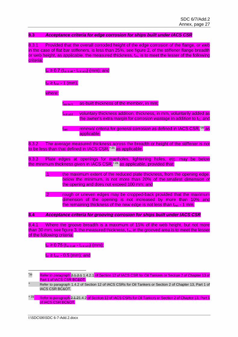
8.3 Acceptance criteria for edge corrosion for ships built under IACS CSR 8.3.1 Provided that the overall corroded height of the edge corrosion of the flange, or web in the case of flat bar stiffeners, is less than 25%, see figure 2, of the stiffener flange breadth or web height, as applicable, the measured thickness, tm, is to meet the lesser of the following criteria:
tm ≥ 0.7 (tas-built - tvol add) (mm); and
tm ≥ tren - 1 (mm), where:
tas-built as-built thickness of the member, in mm; tvol add voluntary thickness addition; thickness, in mm, voluntarily added as
the owner's extra margin for corrosion wastage in addition to tC; and
tren renewal criteria for general corrosion as defined in IACS CSR,*20 as applicable.
8.3.2 The average measured thickness across the breadth or height of the stiffener is not to be less than that defined in IACS CSR,+ 21 as applicable. 8.3.3 Plate edges at openings for manholes, lightening holes, etc. may be below the minimum thickness given in IACS CSR,+ 21 as applicable, provided that:
.1 the maximum extent of the reduced plate thickness, from the opening edge, below the minimum, is not more than 20% of the smallest dimension of the opening and does not exceed 100 mm; and
.2 rough or uneven edges may be cropped-back provided that the maximum
dimension of the opening is not increased by more than 10% and the remaining thickness of the new edge is not less than tren - 1 mm.
8.4 Acceptance criteria for grooving corrosion for ships built under IACS CSR 8.4.1 Where the groove breadth is a maximum of 15% of the web height, but not more than 30 mm, see figure 3, the measured thickness, tm, in the grooved area is to meet the lesser of the following criteria:
tm ≥ 0.75 (tas-built - tvol add) (mm); tm ≥ tren - 0.5 (mm); and
*20 Refer to paragraph 2.1.2.1 1.4.2.1 of Section 12 of IACS CSR for Oil Tankers or Section 2 of Chapter 13 of
Part 1 of IACS CSR BC&OT. + Refer to paragraph 1.4.2 of Section 12 of IACS CSRs for Oil Tankers or Section 2 of Chapter 13, Part 1 of
IACS CSR BC&OT. + 21 Refer to paragraph 2.1.21.4.2 of Section 12 of IACS CSRs for Oil Tankers or Section 2 of Chapter 13, Part 1
of IACS CSR BC&OT.

SDC 6/7/Add.2 Annex, page 28
I:\SDC\06\SDC 6-7-Add.2.docx
tm ≥ 6 mm, where:
tas-built as-built thickness of the member, in mm; tvol add voluntary thickness addition; thickness, in mm, voluntarily added as
the owner's extra margin for corrosion wastage in addition to tC; and tren renewal criteria for general corrosion as defined in IACS CSR,*22 as
applicable.
8.4.2 Structural members with areas of grooving greater than those in 8.4.1 are to be assessed based on the criteria for general corrosion as defined in IACS CSR+22 using the average measured thickness across the plating/stiffener. 89 Reporting and evaluation of survey 89.1 Evaluation of survey report 89.1.1 The data and information on the structural condition of the ship collected during the survey should isare to be evaluated for acceptability and continued structural integrity of the ship. 89.1.2 In case of oil tankers of 130 m in length and upwards (as defined in the International Convention on Load Lines in force), the ship's longitudinal strength should is to be evaluated by using the thickness of structural members measured, renewed and reinforced, as appropriate, during the renewal survey of safety construction carried out after the ship reached 10 years of age, in accordance with the criteria for longitudinal strength of the ship's hull girder for oil tankers specified in annex 1213. 89.1.3 The analysis of data should is to be carried out and endorsed by the Administration or recognized organization authorized by the Administration and the conclusions of the analysis should are to form a part of the condition evaluation report (executive hull summary report). 89.1.4 The final result of the evaluation of the ship's longitudinal strength required in 89.1.2, after renewal or reinforcement work of structural members, if carried out as a result of initial evaluation, should is to be reported as a part of the condition evaluation report (executive hull summary report). 89.2 Reporting 89.2.1 Principles for survey reporting are shown in annex 89. 89.2.2 When a survey is split between different survey stations, a report should is to be made for each portion of the survey. A list of items examined and/or tested (pressure testing, thickness measurements, etc.) and an indication of whether the item has been credited, should is to be made available to the next attending surveyor(s), prior to continuing or completing the survey.
* 22 Refer to paragraph 2.1.2.1 1.4.2.1 of Section 12 of IACS CSR for Oil Tankers or Section 2 of Chapter 13 of
Part 1 of IACS CSR BC&OT.
SDC 6/7/Add.2 Annex, page 29
I:\SDC\06\SDC 6-7-Add.2.docx
89.2.3 A condition evaluation report (executive hull summary report) of the survey and results should are to be issued to the owner as shown in annex 910 and placed on board the ship for reference at future surveys. The condition evaluation report (executive hull summary report) should is to be endorsed by the Administration or recognized organization authorized by the Administration.
SDC 6/7/Add.2 Annex, page 30
I:\SDC\06\SDC 6-7-Add.2.docx
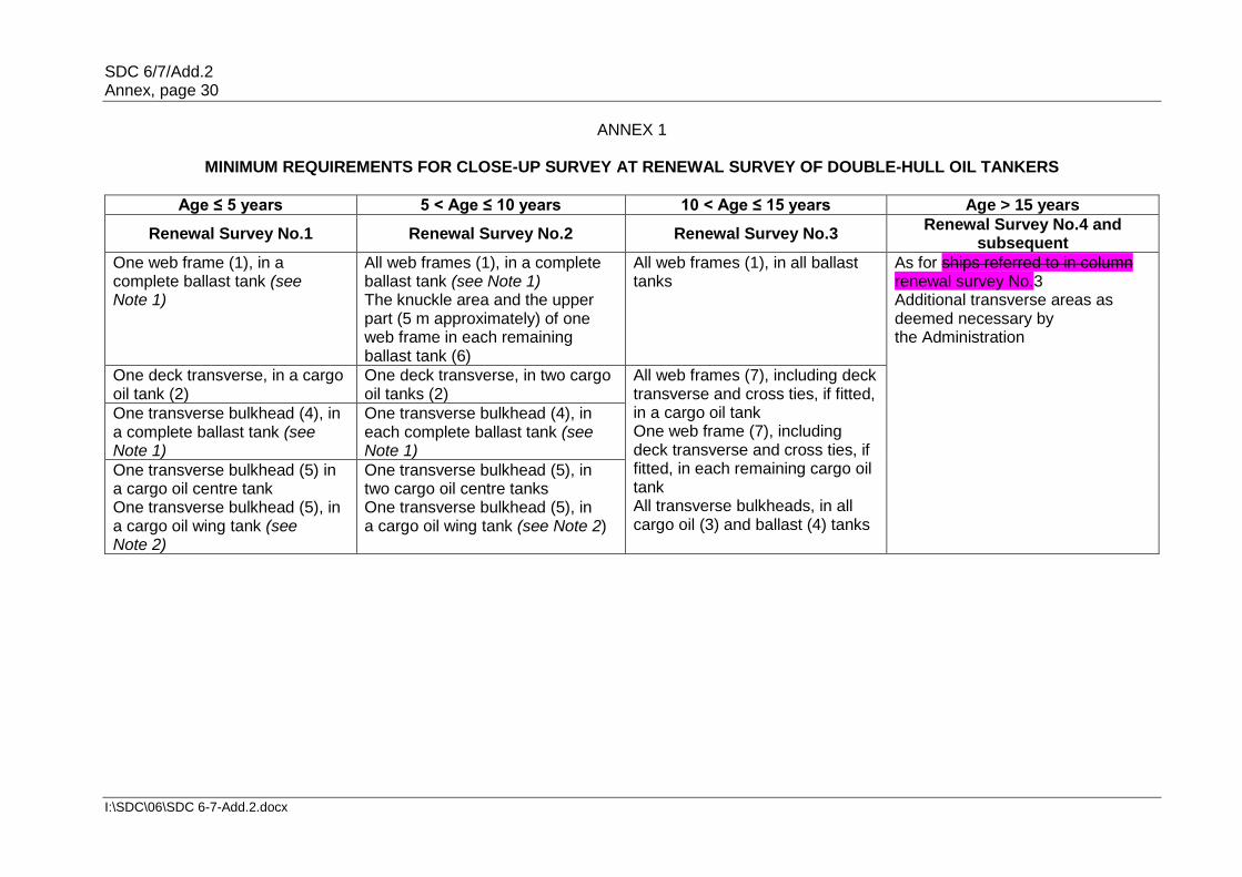
ANNEX 1
MINIMUM REQUIREMENTS FOR CLOSE-UP SURVEY AT RENEWAL SURVEY OF DOUBLE-HULL OIL TANKERS
Age ≤ 5 years 5 < Age ≤ 10 years 10 < Age ≤ 15 years Age > 15 years
Renewal Survey No.1 Renewal Survey No.2 Renewal Survey No.3 Renewal Survey No.4 and
subsequent
One web frame (1), in a complete ballast tank (see Note 1)
All web frames (1), in a complete ballast tank (see Note 1) The knuckle area and the upper part (5 m approximately) of one web frame in each remaining ballast tank (6)
All web frames (1), in all ballast tanks
As for ships referred to in column renewal survey No.3 Additional transverse areas as deemed necessary by the Administration
One deck transverse, in a cargo oil tank (2)
One deck transverse, in two cargo oil tanks (2)
All web frames (7), including deck transverse and cross ties, if fitted, in a cargo oil tank One web frame (7), including deck transverse and cross ties, if fitted, in each remaining cargo oil tank All transverse bulkheads, in all cargo oil (3) and ballast (4) tanks
One transverse bulkhead (4), in a complete ballast tank (see Note 1)
One transverse bulkhead (4), in each complete ballast tank (see Note 1)
One transverse bulkhead (5) in a cargo oil centre tank One transverse bulkhead (5), in a cargo oil wing tank (see Note 2)
One transverse bulkhead (5), in two cargo oil centre tanks One transverse bulkhead (5), in a cargo oil wing tank (see Note 2)
SDC 6/7/Add.2 Annex, page 31
I:\SDC\06\SDC 6-7-Add.2.docx
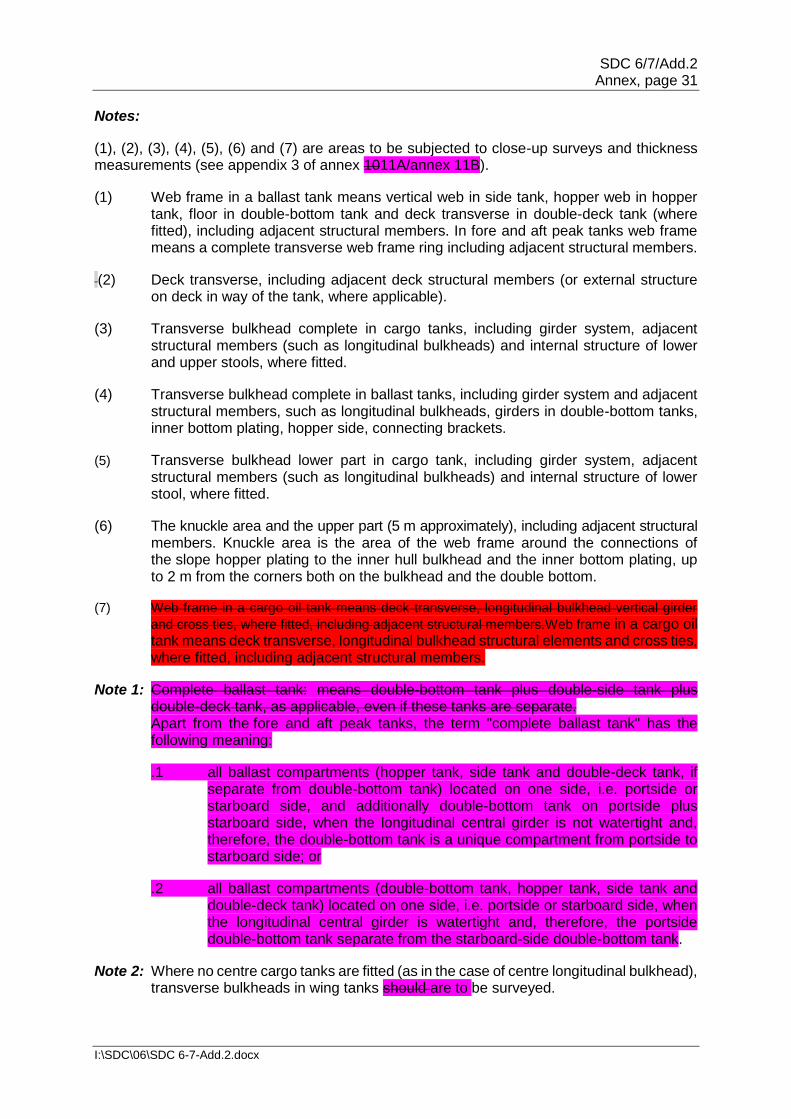
Notes:
(1), (2), (3), (4), (5), (6) and (7) are areas to be subjected to close-up surveys and thickness measurements (see appendix 3 of annex 1011A/annex 11B).
(1) Web frame in a ballast tank means vertical web in side tank, hopper web in hopper tank, floor in double-bottom tank and deck transverse in double-deck tank (where fitted), including adjacent structural members. In fore and aft peak tanks web frame means a complete transverse web frame ring including adjacent structural members.
(2) Deck transverse, including adjacent deck structural members (or external structure on deck in way of the tank, where applicable).
(3) Transverse bulkhead complete in cargo tanks, including girder system, adjacent structural members (such as longitudinal bulkheads) and internal structure of lower and upper stools, where fitted.
(4) Transverse bulkhead complete in ballast tanks, including girder system and adjacent structural members, such as longitudinal bulkheads, girders in double-bottom tanks, inner bottom plating, hopper side, connecting brackets.
(5) Transverse bulkhead lower part in cargo tank, including girder system, adjacent structural members (such as longitudinal bulkheads) and internal structure of lower stool, where fitted.
(6) The knuckle area and the upper part (5 m approximately), including adjacent structural members. Knuckle area is the area of the web frame around the connections of the slope hopper plating to the inner hull bulkhead and the inner bottom plating, up to 2 m from the corners both on the bulkhead and the double bottom.
(7) Web frame in a cargo oil tank means deck transverse, longitudinal bulkhead vertical girder
and cross ties, where fitted, including adjacent structural members.Web frame in a cargo oil tank means deck transverse, longitudinal bulkhead structural elements and cross ties, where fitted, including adjacent structural members.
Note 1: Complete ballast tank: means double-bottom tank plus double-side tank plus double-deck tank, as applicable, even if these tanks are separate. Apart from the fore and aft peak tanks, the term "complete ballast tank" has the following meaning:
.1 all ballast compartments (hopper tank, side tank and double-deck tank, if separate from double-bottom tank) located on one side, i.e. portside or starboard side, and additionally double-bottom tank on portside plus starboard side, when the longitudinal central girder is not watertight and, therefore, the double-bottom tank is a unique compartment from portside to starboard side; or
.2 all ballast compartments (double-bottom tank, hopper tank, side tank and double-deck tank) located on one side, i.e. portside or starboard side, when the longitudinal central girder is watertight and, therefore, the portside double-bottom tank separate from the starboard-side double-bottom tank.
Note 2: Where no centre cargo tanks are fitted (as in the case of centre longitudinal bulkhead), transverse bulkheads in wing tanks should are to be surveyed.

SDC 6/7/Add.2 Annex, page 32
I:\SDC\06\SDC 6-7-Add.2.docx
ANNEX 2
MINIMUM REQUIREMENTS FOR THICKNESS MEASUREMENTS AT RENEWAL SURVEY OF DOUBLE-HULL OIL TANKERS
Age ≤ 5 years 5 < Age ≤ 10 years 10 < Age ≤ 15 years Age > 15 years
1 2 3 4
One section of deck plating for the full beam of the ship within the cargo area
Within the cargo area: - each deck plate - one transverse section
Within the cargo area: - each deck plate - two transverse sections (1) - all wind and water strakes
Within the cargo area: - each deck plate - three transverse sections (1) - each bottom plate
Selected wind and water strakes outside the cargo area
Selected wind and water strakes outside the cargo area
All wind and water strakes in full length
Measurements, for general assessment and recording of corrosion pattern, of those structural members subject to close-up survey according to annex 1
Measurements, for general assessment and recording of corrosion pattern, of those structural members subject to close-up survey according to annex 1
Measurements, for general assessment and recording of corrosion pattern, of those structural members subject to close-up survey according to annex 1
Measurements, for general assessment and recording of corrosion pattern, of those structural members subject to close-up survey according to annex 1
Suspect areas Suspect areas Suspect areas Suspect areas
(1): at least one section should is to be within 0.5L amidships.

SDC 6/7/Add.2 Annex, page 33
I:\SDC\06\SDC 6-7-Add.2.docx
ANNEX 3
MINIMUM REQUIREMENTS FOR TANK TESTING AT RENEWAL SURVEY OF DOUBLE-HULL OIL TANKERS
Age ≤ 5 years Age > 5 years Age > 10 years
1 2 3
All ballast tank boundaries All ballast tank boundaries All ballast tank boundaries
Cargo tank boundaries facing ballast tanks, void spaces, pipe tunnels, representative fuel oil tanks, pump-rooms or cofferdams
Cargo tank boundaries facing ballast tanks, void spaces, pipe tunnels, representative fuel oil tanks, pump-rooms or cofferdams
Cargo tank boundaries facing ballast tanks, void spaces, pipe tunnels, representative fuel oil tanks, pump-rooms or cofferdams
All cargo tank bulkheads which form the boundaries of segregated cargoes
All remaining cargo tank bulkheads
Age of ship (in years at time of renewal survey due date)
Renewal survey No.1 age ≤ 5
Renewal survey No.2 and subsequent age > 5
All ballast tank boundaries
All ballast tank boundaries
Cargo tank boundaries facing ballast tanks, void spaces, pipe tunnels, pump rooms or cofferdams
All cargo tank bulkheads

SDC 6/7/Add.2 Annex, page 34
I:\SDC\06\SDC 6-7-Add.2.docx
ANNEX 4/SHEET 1
REQUIREMENTS FOR EXTENT OF THICKNESS MEASUREMENTS AT AREAS OF SUBSTANTIAL CORROSION OF DOUBLE-HULL OIL TANKERS WITHIN
THE CARGO AREA LENGTH
Renewal survey of double-hull oil tankers
Bottom, inner bottom and hopper structure
Structural member
Extent of measurement Pattern of measurement
Bottom, inner bottom and hopper structure plating
Minimum of three bays across double-bottom tank, including aft bay Measurements around and under all suction bell mouths
Five-point pattern for each panel between longitudinals and floors
Bottom, inner bottom and hopper structure longitudinals
Minimum of three longitudinals in each bay where bottom plating measured
Three measurements in line across flange and three measurements on vertical web
Bottom girders, including the watertight ones
At fore and aft watertight floors and in centre of tanks
Vertical line of single measurements on girder plating with one measurement between each panel stiffener, or a minimum of three measurements
Bottom floors, including the watertight ones
Three floors in bays where bottom plating measured, with measurements at both ends and middle
Five-point pattern over 2 m2 area
Hopper structure web frame ring
Three floors in bays where bottom plating measured
Five-point pattern over 1 m2 of plating. Single measurements on flange
Hopper structure transverse watertight bulkhead or swash bulkhead
- lower ⅓ of bulkhead Five-point pattern over 1 m2 of plating
- upper ⅔ of bulkhead Five-point pattern over 2 m2 of plating
- stiffeners (minimum of three)
For web, five-point pattern over span (two measurements across web at each end and one at centre of span). For flange, single measurements at each end and centre of span
Panel stiffening
Where applicable Single measurements

SDC 6/7/Add.2 Annex, page 35
I:\SDC\06\SDC 6-7-Add.2.docx
ANNEX 4/SHEET 2
REQUIREMENTS FOR EXTENT OF THICKNESS MEASUREMENTS AT AREAS OF SUBSTANTIAL CORROSION OF DOUBLE-HULL OIL TANKERS WITHIN
THE CARGO AREA LENGTH
Renewal survey of double-hull oil tankers within the cargo area length
Deck structure
Structural member
Extent of measurement
Pattern of measurement
Deck plating Two transverse bands across tank
Minimum of three measurements per plate per band
Deck longitudinals Every third longitudinal in each of two bands with a minimum of one longitudinal
Three measurements in line vertically on webs and two measurements on flange (if fitted)
Deck girders and brackets (usually in cargo tanks only)
At fore and aft transverse bulkhead, bracket toes and in centre of tanks
Vertical line of single measurements on web plating with one measurement between each panel stiffener, or a minimum of three measurements. Two measurements across flange. Five-point pattern on girder/bulkhead brackets
Deck transverse webs
Minimum of two webs, with measurements at both ends and middle of span
Five-point pattern over 1 m2 area. Single measurements on flange
Vertical web and transverse bulkhead in wing ballast tank (2 m from deck)
Minimum of two webs, and both transverse bulkheads
Five-point pattern over 1 m2 area
Panel stiffening Where applicable Single measurements

SDC 6/7/Add.2 Annex, page 36
I:\SDC\06\SDC 6-7-Add.2.docx
ANNEX 4/SHEET 3
REQUIREMENTS FOR EXTENT OF THICKNESS MEASUREMENTS AT AREAS OF SUBSTANTIAL CORROSION OF DOUBLE-HULL OIL TANKERS WITHIN
THE CARGO AREA LENGTH
Renewal survey of double-hull oil tankers within the cargo area length
Structure in wing ballast tanks
Structural member
Extent of measurement
Pattern of measurement
Side shell and longitudinal bulkhead plating: - upper strake
and strakes in way of horizontal girders
- all other strakes
Plating between each pair of longitudinals in a minimum of three bays (along the tank) Plating between every third pair of longitudinals in same three bays
Single measurement Single measurement
Side shell and longitudinal bulkhead longitudinals on: - upper strake - all other strakes
Each longitudinal in same three bays Every third longitudinal in same three bays
Three measurements across web and one measurement on flange Three measurements across web and one measurement on flange
Longitudinals brackets
Minimum of three at top, middle and bottom of tank in same three bays
Five-point pattern over area of bracket
Vertical web and transverse bulkheads (excluding deckhead area): - strakes in way
of horizontal girders
- other strakes
Minimum of two webs and both transverse bulkheads Minimum of two webs and both transverse bulkheads
Five-point pattern over approximately 2 m2 area Two measurements between each pair of vertical stiffeners
Horizontal girders Plating on each girder in a minimum of three bays
Two measurements between each pair of longitudinal girder stiffeners
Panel stiffening Where applicable Single measurements

SDC 6/7/Add.2 Annex, page 37
I:\SDC\06\SDC 6-7-Add.2.docx
ANNEX 4/SHEET 4
REQUIREMENTS FOR EXTENT OF THICKNESS MEASUREMENTS AT AREAS OF SUBSTANTIAL CORROSION OF DOUBLE-HULL OIL TANKERS WITHIN
THE CARGO AREA LENGTH
Renewal survey of double-hull oil tankers within the cargo area length
Longitudinal bulkheads in cargo tanks
Structural member
Extent of measurement
Pattern of measurement
Deckhead and bottom strakes, and strakes in way of the horizontal stringers of transverse bulkheads
Plating between each pair of longitudinals in a minimum of three bays
Single measurement
All other strakes Plating between every third pair of longitudinals in same three bays
Single measurement
Longitudinals on deckhead and bottom strakes
Each longitudinal in same three bays
Three measurements across web and one measurement on flange
All other longitudinals
Every third longitudinal in same three bays
Three measurements across web and one measurement on flange
Longitudinals brackets
Minimum of three at top, middle and bottom of tank in same three bays
Five-point pattern over area of bracket
Web frames and cross ties
Three webs with minimum of three locations on each web, including in way of cross tie connections
Five-point pattern over approximately 2 m2 area of webs, plus single measurements on flanges of web frame and cross ties
Lower end brackets (opposite side of web frame)
Minimum of three brackets
Five-point pattern over approximately 2 m2 area of brackets, plus single measurements on bracket flanges

SDC 6/7/Add.2 Annex, page 38
I:\SDC\06\SDC 6-7-Add.2.docx
ANNEX 4/SHEET 5
REQUIREMENTS FOR EXTENT OF THICKNESS MEASUREMENTS AT AREAS OF SUBSTANTIAL CORROSION OF DOUBLE-HULL OIL TANKERS WITHIN
THE CARGO AREA LENGTH
Renewal survey of double-hull oil tankers within the cargo area length
Transverse watertight and swash bulkheads in cargo tanks
Structural member
Extent of measurement
Pattern of measurement
Upper and lower stool, where fitted
Transverse band within 25 mm of welded connection to inner bottom/deck plating Transverse band within 25 mm of welded connection to shelf plate
Five-point pattern between stiffeners over 1 m length
Deckhead and bottom strakes, and strakes in way of horizontal stringers
Plating between pair of stiffeners at three locations: approximately ¼, ½ and ¾ width of tank
Five-point pattern between stiffeners over 1 m length
All other strakes Plating between pair of stiffeners at middle location
Single measurement
Strakes in corrugated bulkheads
Plating for each change of scantling at centre of panel and at flange of fabricated connection
Five-point pattern over approximately 1 m2 of plating
Stiffeners Minimum of three typical stiffeners
For web, five-point pattern over span between bracket connections (two measurements across web at each bracket connection and one at centre of span) For flange, single measurements at each bracket toe and at centre of span
Brackets Minimum of three at top, middle and bottom of tank
Five-point pattern over area of bracket
Horizontal stringers
All stringers with measurements at both ends and middle
Five-point pattern over 1 m2 area, plus single measurements near bracket toes and on flanges
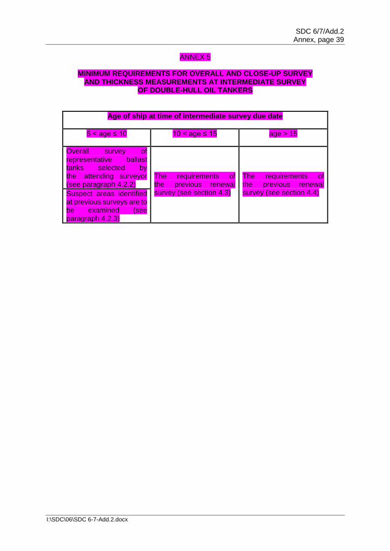
SDC 6/7/Add.2 Annex, page 39
I:\SDC\06\SDC 6-7-Add.2.docx
ANNEX 5
MINIMUM REQUIREMENTS FOR OVERALL AND CLOSE-UP SURVEY AND THICKNESS MEASUREMENTS AT INTERMEDIATE SURVEY
OF DOUBLE-HULL OIL TANKERS
Age of ship at time of intermediate survey due date
5 < age ≤ 10
10 < age ≤ 15 age > 15
Overall survey of representative ballast tanks selected by the attending surveyor (see paragraph 4.2.2)
The requirements of the previous renewal survey (see section 4.3)
The requirements of the previous renewal survey (see section 4.4) Suspect areas identified
at previous surveys are to be examined (see paragraph 4.2.3)
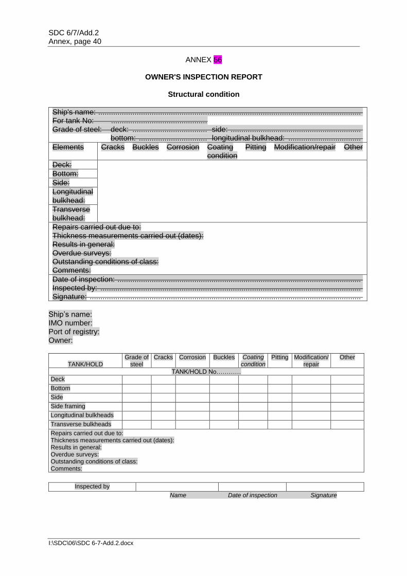
SDC 6/7/Add.2 Annex, page 40
I:\SDC\06\SDC 6-7-Add.2.docx
ANNEX 56
OWNER'S INSPECTION REPORT
Structural condition
Ship's name: ........................................................................................................................... For tank No: ............................................. Grade of steel: deck: ................................... side: .............................................................
bottom: ................................ longitudinal bulkhead: ..................................
Elements Cracks Buckles Corrosion Coating condition
Pitting Modification/repair Other
Deck:
Bottom:
Side:
Longitudinal bulkhead:
Transverse bulkhead:
Repairs carried out due to: Thickness measurements carried out (dates): Results in general: Overdue surveys: Outstanding conditions of class: Comments:
Date of inspection: .................................................................................................................. Inspected by: .......................................................................................................................... Signature: ...............................................................................................................................
Ship’s name: IMO number: Port of registry: Owner:
TANK/HOLD
Grade of steel
Cracks Corrosion Buckles Coating condition
Pitting Modification/repair
Other
TANK/HOLD No………… Deck Bottom Side Side framing Longitudinal bulkheads Transverse bulkheads Repairs carried out due to: Thickness measurements carried out (dates): Results in general: Overdue surveys: Outstanding conditions of class: Comments:
Inspected by Name Date of inspection Signature

SDC 6/7/Add.2 Annex, page 41
I:\SDC\06\SDC 6-7-Add.2.docx
ANNEX 67A
SURVEY PROGRAMME Basic information and particulars
Ship’s name Name of ship:
IMO number:
Flag State:
Port of registry:
Gross tonnage:
Deadweight (metric tonnes):
Length between perpendiculars (m):
Shipbuilder:
Hull number:
Recognized organization (RO):
RO ship identity:
Date of delivery build of the ship:
Owner:
Thickness measurement companyfirm:
1 Preamble 1.1 Scope 1.1.1 The present survey programme covers the minimum extent of overall surveys, close-up surveys, thickness measurements and pressure testing within the cargo area, cargo tanks, ballast tanks, including fore and aft peak tanks, required by the Code. 1.1.2 The arrangements and safety aspects of the survey should are to be acceptable to the attending surveyor(s). 1.2 Documentation All documents used in the development of the survey programme should are to be available on board during the survey as required by section 6. 2 Arrangement of tanks and spaces This section of the survey programme should is to provide information (either in the form of plans or text) on the arrangement of tanks and spaces that fall within the scope of the survey. 3 List of tanks and spaces with information on their use, extent of coatings and
corrosion prevention system This section of the survey programme should is to indicate any changes relating to (and should is to update) the information on the use of the tanks of the ship, the extent of coatings and the corrosion protective system provided in the survey planning questionnaire.

SDC 6/7/Add.2 Annex, page 42
I:\SDC\06\SDC 6-7-Add.2.docx
4 Conditions for survey This section of the survey programme should is to provide information on the conditions for survey, e.g. information regarding cargo hold and tank cleaning, gas freeing, ventilation, lighting, etc. 5 Provisions and method of access to structures This section of the survey programme should is to indicate any changes relating to (and should is to update) the information on the provisions and methods of access to structures provided in the survey planning questionnaire. 6 List of equipment for survey This section of the survey programme should is to identify and list the equipment that will be made available for carrying out the survey and the required thickness measurements. 7 Survey requirements 7.1 Overall survey This section of the survey programme should is to identify and list the spaces that should are to undergo an overall survey for the ship in accordance with 2.4.1. 7.2 Close-up survey This section of the survey programme should is to identify and list the hull structures that should are to undergo a close-up survey for the ship in accordance with 2.4.2. 8 Identification of tanks for tank testing This section of the survey programme should is to identify and list the tanks that should are to undergo tank testing for the ship in accordance with 2.6. 9 Identification of areas and sections for thickness measurements This section of the survey programme should is to identify and list the areas and sections where thickness measurements should are to be taken in accordance with 2.5.1. 10 Minimum thickness of hull structures This section of the survey programme should is to specify the minimum thickness for hull structures of the ship that are subject to the Code (indicate either (a) or preferably (b), if such information is available):
(a) Determined from the attached wastage allowance table and the original thickness to the hull structure plans of the ship;
(b) Given in the following table(s):

SDC 6/7/Add.2 Annex, page 43
I:\SDC\06\SDC 6-7-Add.2.docx
Area or location Original as-built thickness (mm)
Minimum thickness (mm)
Substantial corrosion thickness (mm)
Deck
Plating
Longitudinals
Longitudinal girders
Bottom
Plating
Longitudinals
Longitudinal girders
Ship side
Plating
Longitudinals
Longitudinal girders
Longitudinal bulkhead
Plating
Longitudinals
Longitudinal girders
Inner bottom
Plating
Longitudinals
Longitudinal girders
Transverse bulkheads
Plating
Stiffeners
Transverse web frames, floors and stringers
Plating
Flanges
Stiffeners
Cross ties
Flanges
Webs
Note: The wastage allowance tables should isare to be attached to the survey programme. For vessels built under IACS CSR, the renewal thickness of the hull structure elements is indicated in the appropriate drawings.
11 Thickness measurement companyfirm This section of the survey programme should is to identify changes, if any, relating to the information on the thickness measurement companyfirm provided in the survey planning questionnaire. 12 Damage experience related to the ship This section of the survey programme should is to, using the tables provided below, provide details of the hull damages for at least the last three years in way of the cargo and ballast tanks and void spaces within the cargo area, using the tables provided below. These damages are subject to survey.

SDC 6/7/Add.2 Annex, page 44
I:\SDC\06\SDC 6-7-Add.2.docx
Hull damages sorted by location for this ship
Tank or space number or
area
Possible cause, if known
Description of the damages
Location Repair Date of repair
Hull damages for sister or similar ships
(if available) in the case of design-related damage
Tank or space number or
area
Possible cause, if known
Description of the damages
Location Repair Date of repair
13 Areas identified with substantial corrosion from previous surveys This section of the survey programme should is to identify and list the areas of substantial corrosion from previous surveys. 14 Critical structural areas and suspect areas This section of the survey programme should is to identify and list the critical structural areas and the suspect areas, if such information is available. 15 Other relevant comments and information This section of the survey programme should is to provide any other comments and information relevant to the survey.

SDC 6/7/Add.2 Annex, page 45
I:\SDC\06\SDC 6-7-Add.2.docx
APPENDICES Appendix 1 – List of plans ParagraphThe provisions of 5.1.3.2 requires that main structural plans of cargo and ballast tanks (scantling drawings), including information on regarding use of high tensile steel (HTS), is to be available. This appendix of the survey programme should is to identify and list the main structural plans which form part of the survey programme. Appendix 2 – Survey planning questionnaire The survey planning questionnaire (annex 6B), which has been submitted by the owner, should is to be appended to the survey programme. Appendix 3 – Other documentation This part of the survey programme should is to identify and list any other documentation that forms part of the plan. Prepared by the owner in cooperation with the Administration for compliance with 5.1.3. Date:
(name and signature of authorized owner's representative) Date:
(name and signature of authorized representative of the Administration)

SDC 6/7/Add.2 Annex, page 46
I:\SDC\06\SDC 6-7-Add.2.docx
ANNEX 67B
SURVEY PLANNING QUESTIONNAIRE The following information will enable the owner in cooperation with the Administration to develop a survey programme complying with the requirements of the Code. It is essential that the owner provides, when completing the present questionnaire, up-to-date information. The present questionnaire, when completed, should is to provide all information and material required by the resolution. 1 Particulars Ship's name: IMO number: Flag State: Port of registry: Owner: Recognized organization (RO): Gross tonnage: Deadweight (metric tonnes): Date of deliverybuild: 2 Information on access provision for close-up surveys and thickness
measurement The owner should is to indicate, in the table below, the means of access to the structures subject to close-up survey and thickness measurement. A close-up survey is an examination where the details of structural components are within the close visual inspection range of the attending surveyor, i.e. normally within reach of hand.
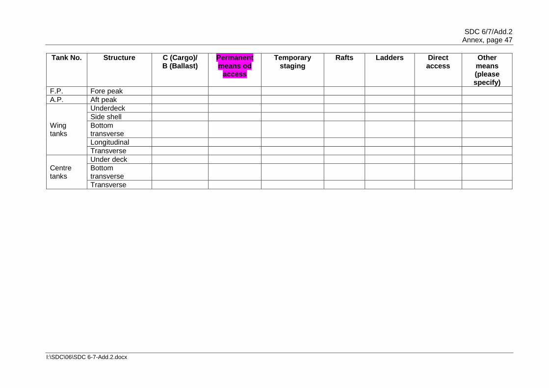
SDC 6/7/Add.2 Annex, page 47
I:\SDC\06\SDC 6-7-Add.2.docx
Tank No. Structure C (Cargo)/ B (Ballast)
Permanent means od
access
Temporary staging
Rafts Ladders Direct access
Other means (please specify)
F.P. Fore peak
A.P. Aft peak
Wing tanks
Underdeck
Side shell
Bottom transverse
Longitudinal
Transverse
Centre tanks
Under deck
Bottom transverse
Transverse
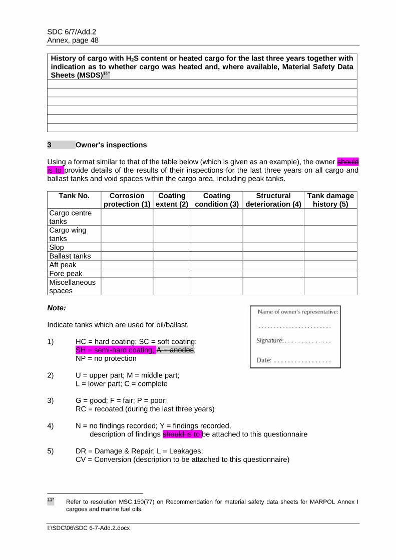
SDC 6/7/Add.2 Annex, page 48
I:\SDC\06\SDC 6-7-Add.2.docx
History of cargo with H2S content or heated cargo for the last three years together with indication as to whether cargo was heated and, where available, Material Safety Data Sheets (MSDS)11*
3 Owner's inspections Using a format similar to that of the table below (which is given as an example), the owner should is to provide details of the results of their inspections for the last three years on all cargo and ballast tanks and void spaces within the cargo area, including peak tanks.
Tank No. Corrosion protection (1)
Coating extent (2)
Coating condition (3)
Structural deterioration (4)
Tank damage history (5)
Cargo centre tanks
Cargo wing tanks
Slop
Ballast tanks
Aft peak
Fore peak
Miscellaneous spaces
Note: Indicate tanks which are used for oil/ballast. 1) HC = hard coating; SC = soft coating; SH = semi-hard coating; A = anodes; NP = no protection 2) U = upper part; M = middle part; L = lower part; C = complete 3) G = good; F = fair; P = poor; RC = recoated (during the last three years) 4) N = no findings recorded; Y = findings recorded, description of findings should is to be attached to this questionnaire 5) DR = Damage & Repair; L = Leakages; CV = Conversion (description to be attached to this questionnaire)
11* Refer to resolution MSC.150(77) on Recommendation for material safety data sheets for MARPOL Annex I
cargoes and marine fuel oils.

SDC 6/7/Add.2 Annex, page 49
I:\SDC\06\SDC 6-7-Add.2.docx
Reports of port State control inspections
List the reports of port State control inspections containing hull structural related deficiencies and relevant information on rectification of the deficiencies:
Safety management system
List non-conformities related to hull maintenance, including the associated corrective actions:
Name and address of the approved thickness measurement companyfirm
SDC 6/7/Add.2 Annex, page 50
I:\SDC\06\SDC 6-7-Add.2.docx
ANNEX 78
PROCEDURES FOR APPROVAL AND CERTIFICATION OF A COMPANYFIRM ENGAGED IN THICKNESS MEASUREMENT OF HULL STRUCTURES
1 Application This guidance applies for certification of the companyfirm which intends to engage in the thickness measurement of hull structures of ships. 2 Procedures for approval and certification Submission of documents 2.1 The following documents should are to be submitted to an organization recognized by the Administration for approval:
.1 outline of the companyfirm, e.g. organization and management structure; .2 experience of the companyfirm in thickness measurement of hull structures of
ships; .3 technicians' careers, i.e. experience of technicians as thickness measurement
operators, technical knowledge and experience of hull structure, etc. Operators should are to be qualified according to a recognized industrial non-destructive test (NDT) standard;
.4 equipment used for thickness measurement such as ultrasonic testing
machines and their maintenance/calibration procedures; .5 a guide for thickness measurement operators; .6 training programmes for technicians for thickness measurement; and .7 measurement record format in accordance with recommended procedures for
thickness measurements (see annex 1011A/annex 11B). Recommended procedures for thickness measurements of double-hull oil tankers are contained in annex 2.
Auditing of the companyfirm 2.2 Upon satisfactory review of the documents submitted, the companyfirm should is to be audited in order to ascertain that the companyfirm is duly organized and managed in accordance with the documents submitted and is capable of conducting thickness measurement of the hull structure of ships. 2.3 Certification is conditional upon an on board demonstration of thickness measurement as well as satisfactory reporting.
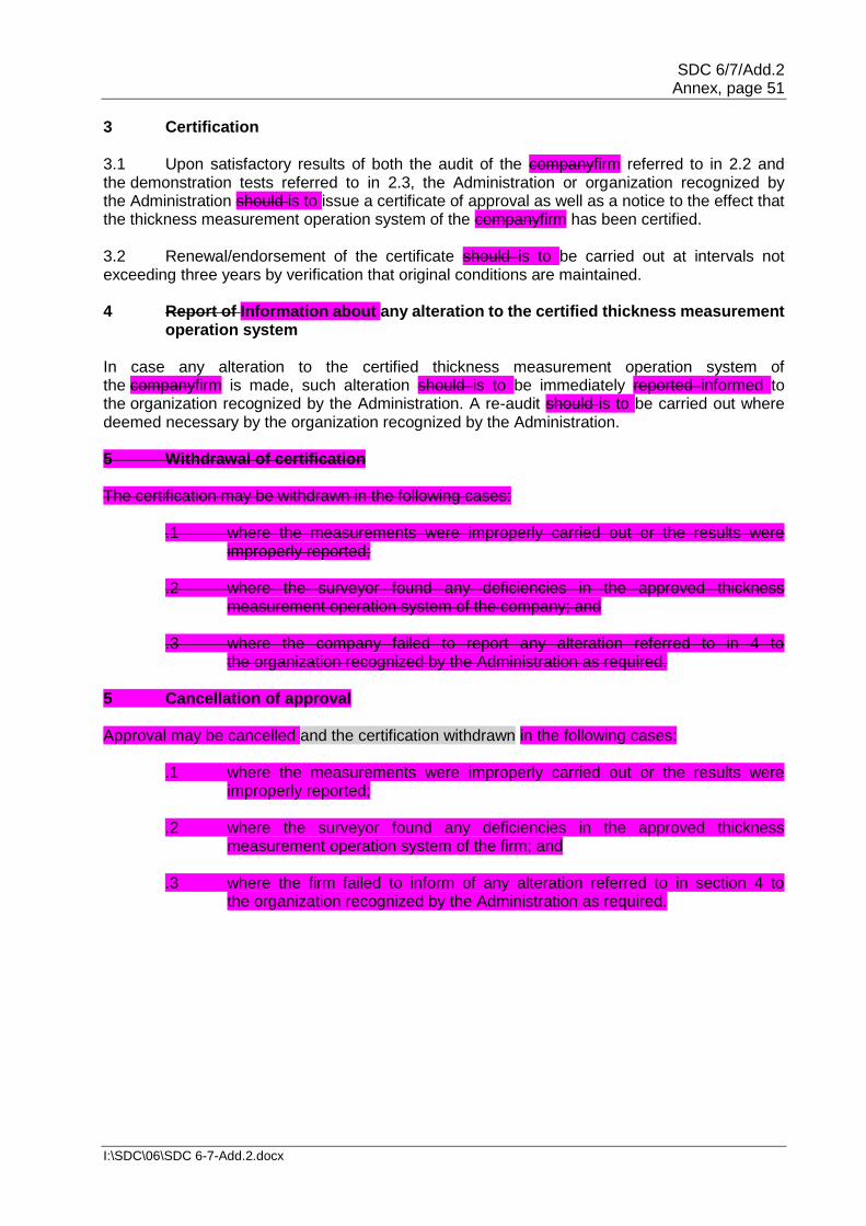
SDC 6/7/Add.2 Annex, page 51
I:\SDC\06\SDC 6-7-Add.2.docx
3 Certification 3.1 Upon satisfactory results of both the audit of the companyfirm referred to in 2.2 and the demonstration tests referred to in 2.3, the Administration or organization recognized by the Administration should is to issue a certificate of approval as well as a notice to the effect that the thickness measurement operation system of the companyfirm has been certified. 3.2 Renewal/endorsement of the certificate should is to be carried out at intervals not exceeding three years by verification that original conditions are maintained. 4 Report of Information about any alteration to the certified thickness measurement
operation system In case any alteration to the certified thickness measurement operation system of the companyfirm is made, such alteration should is to be immediately reported informed to the organization recognized by the Administration. A re-audit should is to be carried out where deemed necessary by the organization recognized by the Administration. 5 Withdrawal of certification The certification may be withdrawn in the following cases:
.1 where the measurements were improperly carried out or the results were improperly reported;
.2 where the surveyor found any deficiencies in the approved thickness
measurement operation system of the company; and .3 where the company failed to report any alteration referred to in 4 to
the organization recognized by the Administration as required. 5 Cancellation of approval Approval may be cancelled and the certification withdrawn in the following cases:
.1 where the measurements were improperly carried out or the results were improperly reported;
.2 where the surveyor found any deficiencies in the approved thickness
measurement operation system of the firm; and .3 where the firm failed to inform of any alteration referred to in section 4 to
the organization recognized by the Administration as required.

SDC 6/7/Add.2 Annex, page 52
I:\SDC\06\SDC 6-7-Add.2.docx
ANNEX 89
SURVEY REPORTING PRINCIPLES As a principle, for oil tankers subject to the Code, the surveyor should include the following contents in his report for survey of hull structure and piping systems, as relevant for the survey. As a principle, for oil tankers subject to this Code, the surveyor(s) are to include the following contents in the report for survey of hull structure and piping systems, as relevant for the survey. The structure of the reporting content may be different, depending on the reporting system of the Administration or by the recognized organization acting on behalf of the Administration. 1 General 1.1 A survey report should is to be generated in the following cases:
.1 in connection with commencement, continuation and/or completion of periodical hull surveys, i.e. annual, intermediate and renewal surveys, as relevant;
.2 when structural damages/defects have been found; .3 when repairs, renewals or modifications have been carried out; and .4 when condition of class (recommendation) has been imposed or deleted.
1.2 The reporting should is to provide:
.1 evidence that prescribed surveys have been carried out in accordance with applicable requirements;
.2 documentation of surveys carried out with findings, repairs carried out and
condition of class (recommendation) imposed or deleted; .3 survey records, including actions taken, which should isare to form an auditable
documentary trail. Survey reports should are to be kept in the survey report file required to be on board;
.4 information for planning of future surveys; and .5 information which may be used as input for maintenance of classification rules
and instructions. 1.3 When a survey is split between different survey stations, a report should is to be made for each portion of the survey. A list of items surveyed, relevant findings and an indication of whether the item has been credited, should are to be made available to the next attending surveyor, prior to continuing or completing the survey. Thickness measurement and tank testing carried out should are also to be listed for the next surveyor. 2 Extent of the survey 2.1 Identification of compartments where an overall survey has been carried out. 2.2 Identification of locations, in each tank, where a close-up survey has been carried out, together with information of the means of access used.

SDC 6/7/Add.2 Annex, page 53
I:\SDC\06\SDC 6-7-Add.2.docx
2.3 Identification of locations, in each tank, where thickness measurement has been carried out.
Note: As a minimum, the identification of location of close-up survey and thickness measurement should areis to include a confirmation with description of individual structural members corresponding to the extent of requirements stipulated in this part of annex B based on type of periodical survey and the ship's age.
Where only partial survey is required, i.e. one web frame ring/one deck transverse, the identification should is to include location within each ballast tank and cargo hold tank by reference to frame numbers. 2.4 For areas in tanks where protective coating is found to be in good condition and the extent of close-up survey and/or thickness measurement has been specially considered, structures subject to special consideration should are to be identified. 2.5 Identification of tanks subject to tank testing. 2.6 Identification of cargo piping systems on deck, including crude oil washing (COW) piping, and ballast piping within cargo and ballast tanks, pump rooms, pipe tunnels, cofferdams and void spaces where:
.1 examination including internal examination of piping with valves and fittings and thickness measurement, as relevant, has been carried out; and
.2 operational test to working pressure has been carried out.
3 Result of survey 3.1 Type, extent and condition of protective coating in each tank, as relevant (rated GOOD, FAIR or POOR), including identification of tanks fitted with anodes. 3.2 Structural condition of each compartment with information on the following, as relevant:
.1 Identification of findings, such as:
.1 corrosion with description of location, type and extent; .2 areas with substantial corrosion; .3 cracks/fractures with description of location and extent; .4 buckling with description of location and extent; and .5 indents with description of location and extent.
.2 Identification of compartments where no structural damage/defects are found.
The report may be supplemented by sketches/photographs. .3 Thickness measurement report should is to be verified and signed by
the surveyor controlling the measurements on board.

SDC 6/7/Add.2 Annex, page 54
I:\SDC\06\SDC 6-7-Add.2.docx
.4 Evaluation result of longitudinal strength of the hull girder of oil tankers of 130 m in length and upwards and over 10 years of age. The following data should is to be included, as relevant:
.1 measured and as-built transverse sectional areas of deck and bottom
flanges; .2 diminution of transverse sectional areas of deck and bottom flanges;
and .3 details of renewals or reinforcements carried out, as relevant (see 4.2).
4 Actions taken with respect to findings 4.1 Whenever the attending surveyor is of the opinion that repairs are required, each item to be repaired should is to be identified in a numbered listsurvey report. Whenever repairs are carried out, details of the repairs effected should are to be reported by making specific reference to relevant items in the numbered listsurvey report. 4.2 Repairs carried out should are to be reported with identification of:
.1 compartment; .2 structural member; .3 repair method (i.e. renewal or modification), including:
.1 steel grades and scantlings (if different from the original); and .2 sketches/photographs, as appropriate;
.4 repair extent; and .5 non-destructive tests (NDT)/tests.
4.3 For repairs not completed at the time of survey, condition of class/recommendation should is to be imposed with a specific time limit for the repairs. In order to provide correct and proper information to the surveyor attending for survey of the repairs, condition of class/recommendation should is to be sufficiently detailed with identification of each item to be repaired. For identification of extensive repairs, reference may be given to the survey report.

SDC 6/7/Add.2 Annex, page 55
I:\SDC\06\SDC 6-7-Add.2.docx
ANNEX 910
CONDITION EVALUATION REPORT (EXECUTIVE HULL SUMMARY REPORT)
Issued upon completion of renewal survey General particulars Ship's name: Class/Administration identity number:Administration/recognized
organization identity number: Previous class/Administration identity number(s):Previous Administration/recognized organization identity number(s): IMO number:
Port of registry: National flag: Previous national flag(s):
Deadweight (metric tonnes):
Gross tonnage: National: ITC (1969):
Date of build: Classification notation: Date of major conversion:
Type of conversion: Owner: Previous owner(s):
1 The survey reports and documents listed below have been reviewed by the undersigned and found to be satisfactory. 2 A summary of the survey is attached herewith on sheet 2. 3 The renewal survey has been completed in accordance with the present Code on (date) ................................
Condition evaluation report (executive hull summary report) completed by
Name
Signature
Title
Office Date
Condition evaluation report (executive hull summary report) verified by
Name
Signature
Title
Office Date
Attached reports and documents: 1) 2) 3) 4) 5) 6)

SDC 6/7/Add.2 Annex, page 56
I:\SDC\06\SDC 6-7-Add.2.docx
Contents of condition evaluation report (executive hull summary report) Part 1 – General particulars: - See front page Part 2 – Report review: - Where and how survey was done Part 3 – Close-up survey: - Extent (which tanks) Part 4 – Cargo and ballast piping
system: - Examined - Operationally tested
Part 5 – Thickness measurements: - Reference to thickness measurement report - Summary of where measured - Separate form indicating the spaces/areas with
substantial corrosion, and corresponding: - thickness diminution - corrosion pattern
Part 6 – Tank corrosion prevention system:
- Separate form indicating: - location of coating/anodes - condition of coating (if applicable)
Part 7 – Repairs: - Identification of tanks/areas Part 8 – Condition of class
(recommendations)/flag State requirements:
Part 9 – Memoranda: - Acceptable defects - Any points of attention for future surveys,
e.g. for suspect areas - Extended annual/intermediate survey due to
coating breakdown Part 10 – Evaluation results of the
ship's longitudinal strength (for oil tankers of 130 m in length and upwards and over 10 years of age)
Part 11 – Conclusion: - Statement on evaluation/ verification of survey report
Extract of thickness measurements for ships not built under IACS CSR Reference is made to the thickness measurement report:
Position of substantially corroded tanks/areas1 or areas with deep pitting3
Thickness diminution [%]
Corrosion pattern2
Remarks: (e.g. reference to
attached sketches)
Notes: 1 Substantial corrosion, i.e. 75 to 100% of acceptable margins wasted. 2 P = Pitting
C = Corrosion in general 3 Any bottom plating with a pitting intensity of 20% or more, with wastage in the substantial
corrosion range or having an average depth of pitting of ⅓ or more of actual plate thickness should us to be noted.

SDC 6/7/Add.2 Annex, page 57
I:\SDC\06\SDC 6-7-Add.2.docx
Extract of thickness measurements for ships built under IACS CSR
Reference is made to the thickness measurements report:
Position of substantially corroded tanks/areas1 or areas
with deep pitting
tm - tren (mm) Corrosion pattern2
Remarks (e.g. reference to
attached sketches)
Notes: 1 Substantial corrosion, an extent of corrosion such that the assessment of the corrosion
pattern indicates a measured thickness between tren + 0.5 mm and tren. 2 P = Pitting
C = Corrosion in general Areas with deep pitting assessed according to section 8.2 are to be recorded in this column.
Tank corrosion prevention systemprotection
Tank Nos.1 Tank corrosion prevention
protectionsystem2
Coating condition3 Remarks
Notes: 1 All segregated ballast tanks and combined cargo/ballast tanks should are to be listed. 2 C = Coating NP = No protection 3 Coating condition according to the following standard:
GOOD condition with only minor spot rusting. FAIR condition with local breakdown of coating at edges of stiffeners and weld connections and/or light rusting over 20% or more of areas under consideration, but less than as defined for POOR condition. POOR condition with general breakdown of coating over 20% or more of areas or hard scale at 10% or more of areas under consideration.
If coating condition less than GOOD is given, extended annual surveys should are to be introduced. This should is to be noted in part 9 of the Contents of condition evaluation report (executive hull summary report).

SDC 6/7/Add.2 Annex, page 58
I:\SDC\06\SDC 6-7-Add.2.docx
Evaluation result of longitudinal strength of the hull girder of oil tankers of 130 m in length and upwards and of over 10 years of age (of sections 1, 2 and 3 below, only one applicable section should is to be completed) 1 This section applies to ships regardless of the date of construction: Transverse sectional areas of deck flange (deck plating and deck longitudinals) and bottom flange (bottom shell plating and bottom longitudinals) of the ship's hull girder have been calculated by using the thickness measured, renewed or reinforced, as appropriate, during the renewal survey of the Cargo Ship Safety Construction Certificate or the Cargo Ship Safety Certificate (SC renewal survey) most recently conducted after the ship reached 10 years of age, and found that the diminution of the transverse sectional area does not exceed 10% of the as-built area, as shown in the following table:
Table 1 – Transverse sectional area of hull girder flange
Measured As-built Diminution
Transverse section 1
Deck flange cm2 cm2 cm2 (%)
Bottom flange cm2 cm2 cm2 (%)
Transverse section 2
Deck flange cm2 cm2 cm2 (%)
Bottom flange cm2 cm2 cm2 (%)
Transverse section 3
Deck flange cm2 cm2 cm2 (%)
Bottom flange cm2 cm2 cm2 (%)
2 This section applies to ships constructed on or after 1 July 2002: Section moduli of transverse section of the ship's hull girder have been calculated by using the thickness of structural members measured, renewed or reinforced, as appropriate, during the SC renewal survey most recently conducted after the ship reached 10 years of age in accordance with the provisions of paragraph 2.2.1.1 of annex 1213, and are found to be within their diminution limits determined by the Administration, taking into account the recommendations recommended diminution limit adopted by IMO resolution MSC.108(73): 90% of the required section modulus for new buildings specified in IACS' Unified Requirements S7 (C=1.0Cn is to be used for the purpose of this calculation) or S11, whichever is the greaterthe Organization12, as shown in the following table:
Table 2 – Transverse section modulus of hull girder
Zact (cm3)1 Zreq (cm3)2 Remarks
Transverse section 1
Upper deck
Bottom
Transverse section 2
Upper deck
Bottom
Transverse section 3
Upper deck
Bottom
Notes: 1 Zact means the actual section moduli of the transverse section of the ship's hull girder
calculated by using the thickness of structural members measured, renewed or reinforced, as appropriate, during the SC renewal survey, in accordance with the provisions of paragraph 2.2.1.1 of annex 1213.
12 Refer to resolution MSC.108(73) on Recommendations on compliance with the requirements of
paragraph 2.2.1.1 of annex 12 to annex B to resolution A.744(18). Refer to section 2 of Annex 13.

SDC 6/7/Add.2 Annex, page 59
I:\SDC\06\SDC 6-7-Add.2.docx
2 Zreq means the diminution limit of the longitudinal bending strength of ships, as calculated in accordance with the provisions of paragraph 2.2.1.1 of annex 1213.
The calculation sheets for Zact should isare to be attached to this report. 3 This section applies to ships constructed before 1 July 2002: Section moduli of transverse sections of the ship's hull girder have been calculated by using the thickness of structural members measured, renewed or reinforced, as appropriate, during the SC renewal survey most recently conducted after the ship reached 10 years of age in accordance with the provisions of paragraph 2.2.1.2 of annex 12, and found to meet the criteria required by the Administration or the recognized classification society and that Zact is not less than Zmc (defined in note 2 below) as specified in appendix 2 to annex 12, as shown in the following table. This section applies to ships constructed before 1 July 2002: Section moduli of transverse sections of the ship's hull girder have been calculated by using the thickness of structural members measured, renewed or reinforced, as appropriate, during the SC renewal survey most recently conducted after the ship reached 10 years of age in accordance with the provisions of paragraph 2.2.1.2 of annex 1213, and found to meet the criteria required by the Administration or the recognized organization and that Zact is not less than Zmc (defined in note 2 below) as specified in appendix 2 to annex 1213, as shown in the following table. Describe the criteria for acceptance of the minimum section moduli of the ship's hull girder for ships in service required by the Administration or the recognized classification societyorganization.
Table 3 – Transverse section modulus of hull girder
Zact (cm3)1 Zmc (cm3)2 Remarks
Transverse section 1
Upper deck
Bottom
Transverse section 2
Upper deck
Bottom
Transverse section 3
Upper deck
Bottom
Notes: 1 As defined in note 1 of table 2. 2 Zmc means the diminution limit of minimum section modulus calculated in accordance
with the provisions of paragraph 2.2.1.2 of annex 1213.

SDC 6/7/Add.2 Annex, page 60
I:\SDC\06\SDC 6-7-Add.2.docx
ANNEX 1011A
RECOMMENDED PROCEDURES FOR THICKNESS MEASUREMENTS OF DOUBLE-HULL OIL TANKERS NOT BUILT UNDER IACS CSR*
General 1 These procedures should be used for recording thickness measurements as required by annexes 2 and 4. 2 Reporting forms TM1-DHT, TM2-DHT(i), TM2-DHT(ii), TM3-DHT, TM4-DHT, TM5-DHT and TM6-DHT, set out in appendix 2, should be used for recording thickness measurements and the maximum allowable diminution should be stated. The maximum allowable diminution could be stated in an attached document. 3 Appendix 3 contains guidance diagrams and notes relating to the reporting forms and the requirements for thickness measurement. 4 The reporting forms should, where appropriate, be supplemented by data presented on structural sketches.
* This annex is recommendatory.

SDC 6/7/Add.2 Annex, page 61
I:\SDC\06\SDC 6-7-Add.2.docx
Appendix 1
GENERAL PARTICULARS Ship's name: ............................................................................................................................ IMO number: ........................................................................................................................... Class/Administration identity number: ....................................................................................... Port of registry: ........................................................................................................................ Gross tonnage: ........................................................................................................................ Deadweight: ............................................................................................................................ Date of build: ........................................................................................................................... Classification society: .............................................................................................................. __________________________________________________________________________ Name of companyfirm performing thickness measurement: .................................................... Thickness measurement companyfirm y certified by: .............................................................. Certificate number: .................................................................................................................. Certificate valid from: .......................................... to ........................................................... Place of measurement: ............................................................................................................ First date of measurement: ...................................................................................................... Last date of measurement: ...................................................................................................... Renewal survey/intermediate survey13* due: ............................................................................ Details of measurement equipment: ........................................................................................ Qualification of operator: ......................................................................................................... __________________________________________________________________________ Report number: .................................................. consisting of ............................... pages Name of operator: .............................................. Name of surveyor: ................................. Signature of operator: ......................................... Signature of surveyor: ............................ CompanyFirm official stamp: .............................. Administration: .......................................
Official stamp
13* Delete as appropriate.
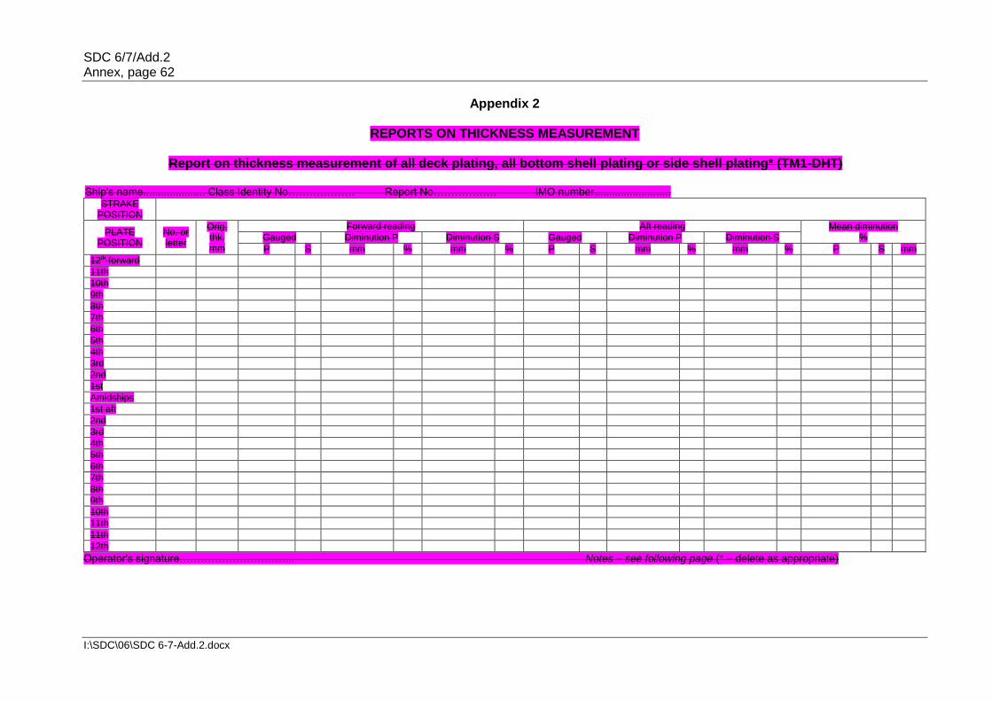
SDC 6/7/Add.2 Annex, page 62
I:\SDC\06\SDC 6-7-Add.2.docx
Appendix 2
REPORTS ON THICKNESS MEASUREMENT
Report on thickness measurement of all deck plating, all bottom shell plating or side shell plating* (TM1-DHT)
Ship's name..................... Class Identity No………………. Report No……………… IMO number.......................... STRAKE
POSITION
PLATE POSITION
No. or letter
Orig. thk. mm
Forward reading Aft reading Mean diminution % Gauged Diminution P Diminution S Gauged Diminution P Diminution S
P S mm % mm % P S mm % mm % P S mm
12th forward
11th
10th
9th
8th
7th
6th
5th
4th
3rd
2nd
1st
Amidships
1st aft
2nd
3rd
4th
5th
6th
7th
8th
9th
10th
11th
11th
12th
Operator's signature…………………………... Notes – see following page (* – delete as appropriate)

SDC 6/7/Add.2 Annex, page 63
I:\SDC\06\SDC 6-7-Add.2.docx
TM1-DHT Report on thickness measurement of all deck plating, all bottom shell plating or side shell plating*
Ship's name…….……………..................... IMO number.......................... Class identity No.......................... Report No………………
Operator's signature.................. Notes – see following page
* Delete as appropriate.
STRAKE POSITION
PLATE
POSITION
No. or
letter
Org. thk. mm
Forward reading Aft reading Mean diminution
mm
Maximum allowable diminution
Gauged Diminution P
Diminution S
Gauged Diminution P
Diminution S
P S mm % mm % P S mm % mm % P S mm
12th forward
11th
10th
9th
8th
7th
6th
5th
4th
3rd
2nd
1st
Amidships
1st aft
2nd
3rd
4th
5th
6th
7th
8th
9th
10th
11th
12th

SDC 6/7/Add.2 Annex, page 64
I:\SDC\06\SDC 6-7-Add.2.docx
Notes to the report TM1-DHT: 1 This report should be used for recording the thickness measurement of:
.1 All strength deck plating within the cargo area. .2 All keel, bottom shell plating and bilge plating within the cargo area. .3 Side shell plating including selected wind and water strakes outside cargo
area. .4 All wind and water strakes within cargo area.
2 The strake position should be clearly indicated as follows:
.1 For strength deck indicate the number of the strake of plating inboard from the stringer plate.
.2 For bottom plating indicate the number of the strake of plating outboard from
the keel plate. .3 For side shell plating give number of the strake of plating below sheerstrake
and letter as shown on shell expansion. 3 Measurements should be taken at the forward and aft areas of all and where plates
cross ballast/cargo tank boundaries, separate measurements for the area of plating in way of each type of tank should be recorded.
4 The single measurements recorded should represent the average of multiple
measurements. 5 The maximum allowable diminution could be stated in an attached document.

SDC 6/7/Add.2 Annex, page 65
I:\SDC\06\SDC 6-7-Add.2.docx
Report on thickness measurement of shell and deck plating (one, two or three transverse sections) (TM2-DHT(i))
Ship's name..................... Class Identity No………………. Report No……………… IMO number.......................... STRENGTH DECK AND SHEERSTRAKE PLATING
FIRST TRANSVERSE SECTION AT FRAME
NUMBER…. SECOND TRANSVERSE SECTION AT FRAME
NUMBER…. THIRD TRANSVERSE SECTION AT FRAME NUMBER….
STRAKE POSITION
No. or letter
Orig. thk.
Max allow. dimin.
Gauged Diminution
P Diminution
S No. or letter
Orig. thk.
Max allow. dimin.
Gauged Diminution
P Diminution
S No. or
letter
Orig. thk.
Max allow. dimin.
Gauged Diminution
P Diminution
S
mm mm P S mm % mm % mm mm P S mm % mm % mm mm P S mm % mm %
Stringer plate
1st strake inboard
2nd
3rd
4th
5th
6th
7th
8th
9th
10th
11th
12th
13th
14th
centre strake
sheerstrake
TOPSIDE TOTAL
Operator's signature………………………….........………… Notes – see following page

SDC 6/7/Add.2 Annex, page 66
I:\SDC\06\SDC 6-7-Add.2.docx
TM2-DHT(i) Report on thickness measurement of shell and deck plating (one, two or three transverse sections)
Ship's name…….……………..................... IMO number.......................... Class identity No.......................... Report No………………
STRENGTH DECK AND SHEERSTRAKE PLATING
FIRST TRANSVERSE SECTION AT FRAME NUMBER…. SECOND TRANSVERSE SECTION AT FRAME
NUMBER…. THIRD TRANSVERSE SECTION AT FRAME NUMBER….
STRAKE POSITION
No. or
letter
Orig. thk.
Max allow. dimin.
Gauged Diminution
P Diminution
S No. or
letter
Orig. thk.
Max allow. dimin.
Gauged Diminution
P Diminution
S No. or
letter
Orig. thk.
Max allow. dimin.
Gauged Diminution
P Diminution
S
mm mm P S mm % mm % mm mm P S mm % mm % mm mm P S mm % mm %
Stringer plate
1st strake inboard
2nd
3rd
4th
5th
6th
7th
8th
9th
10th
11th
12th
13th
14th
centre strake
sheerstrake
TOPSIDE TOTAL
Operator's signature.................. Notes – see following page

SDC 6/7/Add.2 Annex, page 67
I:\SDC\06\SDC 6-7-Add.2.docx
Notes to the report TM2-DHT(i): 1 This report form should be used for recording the thickness measurements of strength
deck plating and sheerstrake plating transverse sections:
One, two or three sections within the cargo area comprising of the structural items (0), (1) and (2) as shown on the diagrams of typical transverse sections illustrated in appendix 3.
2 The topside area comprises deck plating, stringer plate and sheerstrake (including
rounded gunwales). 3 The exact frame station of measurement should be stated. 4 The single measurements recorded should represent the average of multiple
measurements. 5 The maximum allowable diminution could be stated in an attached document.

SDC 6/7/Add.2 Annex, page 68
I:\SDC\06\SDC 6-7-Add.2.docx
Report on thickness measurement of shell and deck plating (one, two or three transverse sections) (TM2-DHT(ii))
Ship's name..................... Class Identity No………………. Report No……………… IMO number.......................... SHELL PLATING
FIRST TRANSVERSE SECTION AT FRAME
NUMBER…. SECOND TRANSVERSE SECTION AT FRAME NUMBER…. THIRD TRANSVERSE SECTION AT FRAME NUMBER….
STRAKE POSITION
No. or letter
Orig. thk.
Max allow. dimin.
Gauged Diminution
P Diminution
S No. or
letter
Orig. thk.
Max allow. dimin.
Gauged Diminution
P Diminution
S No. or
letter
Orig. thk.
Max allow. dimin.
Gauged Diminution
P Diminution
S
mm mm P S mm % mm % mm mm P S mm % mm % mm mm P S mm % mm %
1st below sheerstrake
2nd
3rd
4th
5th
6th
7th
8th
9th
10th
11th
12th
13th
14th
15th
16th
17th
18th
19th
20th
keel strake
BOTTOM TOTAL
Operator's signature………………………….........………… Notes – see following page
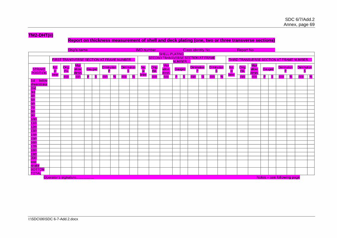
SDC 6/7/Add.2 Annex, page 69
I:\SDC\06\SDC 6-7-Add.2.docx
TM2-DHT(ii) Report on thickness measurement of shell and deck plating (one, two or three transverse sections)
Ship's name…….……………..................... IMO number.......................... Class identity No.......................... Report No………………
SHELL PLATING
FIRST TRANSVERSE SECTION AT FRAME NUMBER…. SECOND TRANSVERSE SECTION AT FRAME
NUMBER…. THIRD TRANSVERSE SECTION AT FRAME NUMBER….
STRAKE POSITION
No. or
letter
Orig. thk.
Max allow. dimin.
Gauged Diminution
P Diminution
S No. or
letter
Orig. thk.
Max allow. dimin.
Gauged Diminution
P Diminution
S No. or
letter
Orig. thk.
Max allow. dimin.
Gauged Diminution
P Diminution
S
mm mm P S mm % mm % mm mm P S mm % mm % mm mm P S mm % mm %
1st below sheerstrake
2nd
3rd
4th
5th
6th
7th
8th
9th
10th
11th
12th
13th
14th
15th
16th
17th
18th
19th
20th
keel strake
BOTTOM TOTAL
Operator's signature.................. Notes – see following page

SDC 6/7/Add.2 Annex, page 70
I:\SDC\06\SDC 6-7-Add.2.docx
Notes to the report TM2-DHT(ii): 1 This report form should be used for recording the thickness measurements of shell
plating transverse sections:
One, two or three sections within the cargo area comprising of the structural items (3), (4) and (5) and (6) as shown on the diagrams of typical transverse sections illustrated in appendix 3.
2 The bottom area comprises keel, bottom and bilge plating. 3 The exact frame station of measurement should be stated. 4 The single measurements recorded should represent the average of multiple
measurements. 5 The maximum allowable diminution could be stated in an attached document.

SDC 6/7/Add.2 Annex, page 71
I:\SDC\06\SDC 6-7-Add.2.docx
Report on thickness measurement of longitudinal members (one, two or three transverse sections) (TM3-DHT)
Ship's name..................... Class Identity No………………. Report No……………… IMO number..........................
FIRST TRANSVERSE SECTION AT FRAME
NUMBER…. SECOND TRANSVERSE SECTION AT FRAME NUMBER…. THIRD TRANSVERSE SECTION AT FRAME NUMBER….
STRUCTURAL MEMBER
Item no.
Orig. thk.
Max allow. dimin.
Gauged Diminution
P Diminution
S Item no.
Orig. thk.
Max allow. dimin.
Gauged Diminution
P Diminution
S Item no.
Orig. thk.
Max allow. dimin.
Gauged Diminution
P Diminution
S
mm mm P S mm % mm % mm mm P S mm % mm % mm mm P S mm % mm %
Operator's signature………………………….........………… Notes – see following page

SDC 6/7/Add.2 Annex, page 72
I:\SDC\06\SDC 6-7-Add.2.docx
TM3-DHT Report on thickness measurement of longitudinal members (one, two or three transverse sections)
Ship's name…….……………..................... IMO number.......................... Class identity No.......................... Report No………………
FIRST TRANSVERSE SECTION AT FRAME
NUMBER…. SECOND TRANSVERSE SECTION AT FRAME
NUMBER…. THIRD TRANSVERSE SECTION AT FRAME
NUMBER….
STRUCTURAL MEMBER
Item no.
Orig. thk.
Max allow. dimin.
Gauged Diminution
P Diminution
S Item no.
Orig. thk.
Max allow. dimin.
Gauged Diminution
P Diminution
S Item no.
Orig. thk.
Max allow. dimin.
Gauged Diminution
P Diminution
S
mm mm P S mm % mm % mm mm P S mm % mm % mm mm P S mm % mm %
Operator's signature.................. Notes – see following page

SDC 6/7/Add.2 Annex, page 73
I:\SDC\06\SDC 6-7-Add.2.docx
Notes to the report TM3-DHT: 1 This report should be used for recording the thickness measurements of longitudinal
members at transverse sections:
One, two or three sections within the cargo area comprising of the appropriate structural items (10) to (29) as shown on the diagrams of typical transverse sections illustrated in appendix 3.
2 The exact frame station of measurement should be stated. 3 The single measurements recorded should represent the average of multiple
measurements. 4 The maximum allowable diminution could be stated in an attached document.
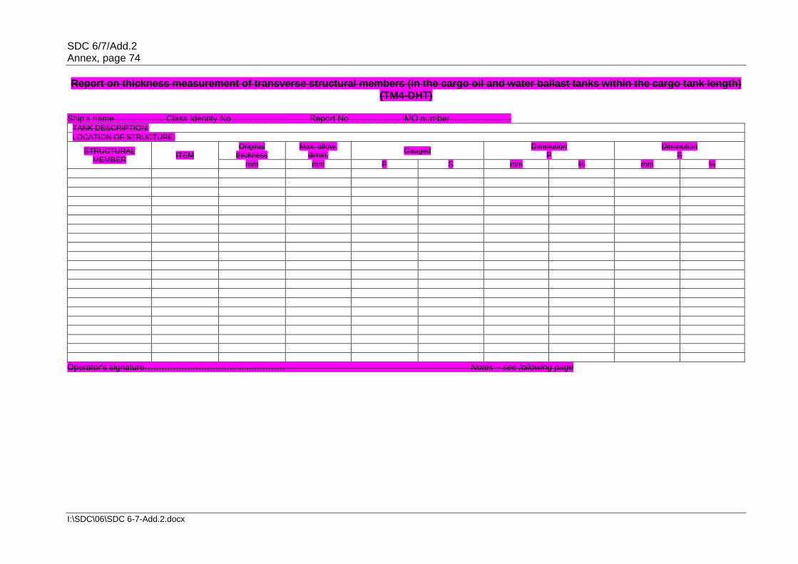
SDC 6/7/Add.2 Annex, page 74
I:\SDC\06\SDC 6-7-Add.2.docx
Report on thickness measurement of transverse structural members (in the cargo oil and water ballast tanks within the cargo tank length) (TM4-DHT)
Ship's name..................... Class Identity No………………. Report No……………… IMO number..........................
TANK DESCRIPTION:
LOCATION OF STRUCTURE:
STRUCTURAL MEMBER
ITEM Original
thickness Max. allow.
dimin. Gauged
Diminution P
Diminution S
mm mm P S mm % mm %
Operator's signature………………………….........………… Notes – see following page
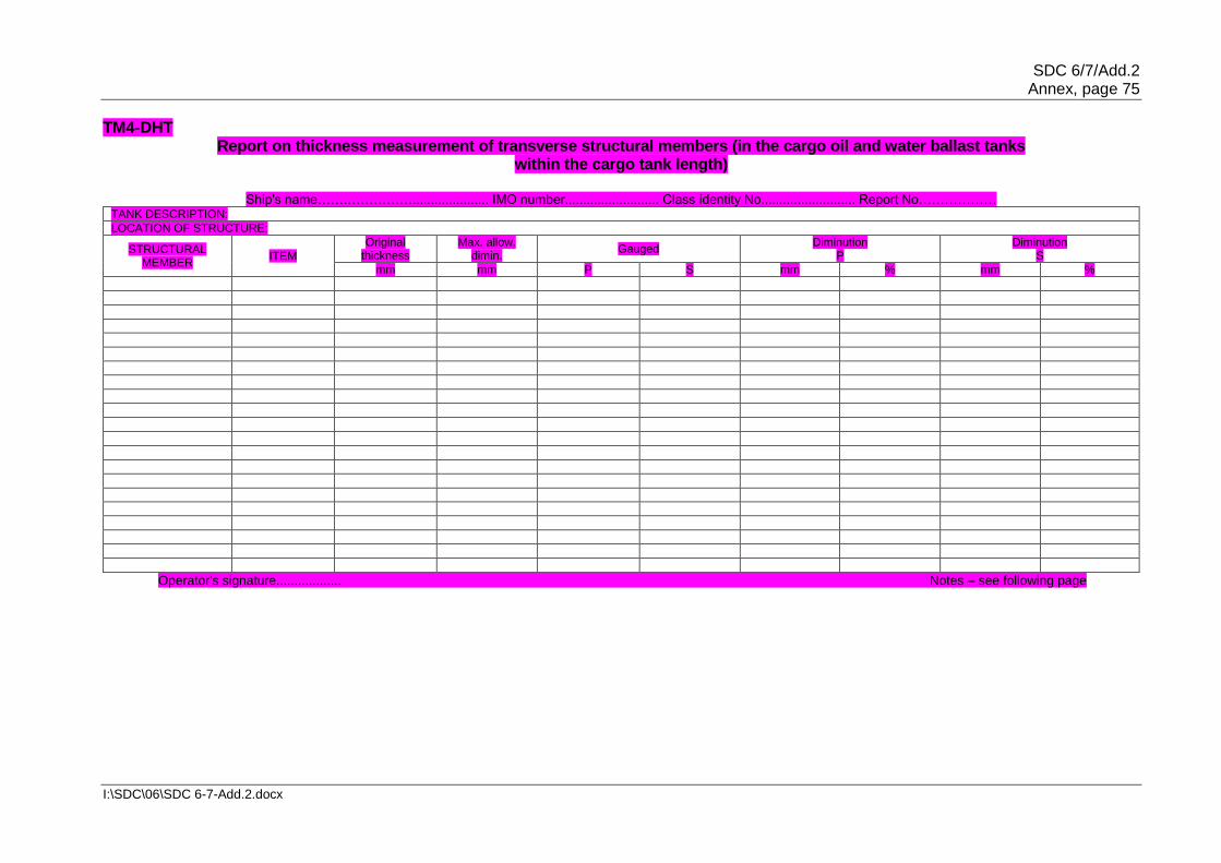
SDC 6/7/Add.2 Annex, page 75
I:\SDC\06\SDC 6-7-Add.2.docx
TM4-DHT Report on thickness measurement of transverse structural members (in the cargo oil and water ballast tanks
within the cargo tank length)
Ship's name…….……………..................... IMO number.......................... Class identity No.......................... Report No……………… TANK DESCRIPTION:
LOCATION OF STRUCTURE:
STRUCTURAL MEMBER
ITEM
Original thickness
Max. allow. dimin.
Gauged Diminution
P Diminution
S
mm mm P S mm % mm %
Operator's signature.................. Notes – see following page

SDC 6/7/Add.2 Annex, page 76
I:\SDC\06\SDC 6-7-Add.2.docx
Notes to the report TM4-DHT: 1 This report should be used for recording the thickness measurements of transverse
structural members, comprising of the appropriate structural items (30) to (36) as shown on diagrams of typical transverse sections illustrated in appendix 3.
2 Guidance for areas of measurement is indicated in appendix 3. The single
measurements recorded should represent the average of multiple measurements. 3 The maximum allowable diminution could be stated in an attached document.

SDC 6/7/Add.2 Annex, page 77
I:\SDC\06\SDC 6-7-Add.2.docx
Report on thickness measurement of W.T./O.T. transverse bulkheads (within the cargo tank or cargo hold spaces) (TM5-DHT)
Ship's name..................... Class Identity No………………. Report No……………… IMO number.......................... TANK/HOLD description
LOCATION OF STRUCTURE: FRAME NO:
STRUCTURAL COMPONENT (Plating, Stiffener)
Original thickness
Max. allow. dimin. Gauged Diminution
P Diminution
S
mm mm P S mm % mm %
Operator's signature………………………….........………… Notes – see following page

SDC 6/7/Add.2 Annex, page 78
I:\SDC\06\SDC 6-7-Add.2.docx
TM5-DHT Report on thickness measurement of watertight/oiltight transverse bulkheads
(within the cargo tank or cargo hold spaces)
Ship's name…….……………..................... IMO number.......................... Class identity No.......................... Report No……………… TANK/HOLD description
LOCATION OF STRUCTURE: FRAME NO:
STRUCTURAL COMPONENT (Plating, Stiffener)
Original thickness
Max. allow. dimin. Gauged Diminution
P Diminution
S
mm mm P S mm % mm %
Operator's signature.................. Notes – see following page

SDC 6/7/Add.2 Annex, page 79
I:\SDC\06\SDC 6-7-Add.2.docx
Notes to the report TM5-DHT: 1 This report should be used for recording the thickness measurement of W.T./O.T.
transverse bulkheads. 2 Guidance for areas of measurement is indicated in appendix 3. 3 The single measurements recorded should represent the average of multiple
measurements. 4 The maximum allowable diminution could be stated in an attached document.

SDC 6/7/Add.2 Annex, page 80
I:\SDC\06\SDC 6-7-Add.2.docx
Report on thickness measurement of miscellaneous structural members (TM6-DHT)
Ship's name..................... IMO number.......................... Class Identity No………………. Report No……………… STRUCTURAL MEMBER: SKETCH
LOCATION OF STRUCTURE:
Description Org. thk. Max. allow. dimin.
Gauged Diminution P
Diminution S
mm mm P S mm % mm %
Operator's signature………………………….........………… Notes – see following page

SDC 6/7/Add.2 Annex, page 81
I:\SDC\06\SDC 6-7-Add.2.docx
TM6-DHT Report on thickness measurement of miscellaneous structural members
Ship's name…….……………..................... IMO number.......................... Class identity No.......................... Report No………………
STRUCTURAL MEMBER: SKETCH
LOCATION OF STRUCTURE:
Description Org. thk. Max. allow. dimin.
Gauged Diminution P
Diminution S
mm mm P S mm % mm %
Operator's signature.................. Notes – see following page

SDC 6/7/Add.2 Annex, page 82
I:\SDC\06\SDC 6-7-Add.2.docx
Notes to the report TM6-DHT: 1 This report should be used for recording the thickness measurement of miscellaneous
structural members. 2 The single measurements recorded should represent the average of multiple
measurements. 3 The maximum allowable diminution could be stated in an attached document.

SDC 6/7/Add.2 Annex, page 83
I:\SDC\06\SDC 6-7-Add.2.docx
Appendix 3
GUIDANCE ON THICKNESS MEASUREMENT – DOUBLE-HULL OIL TANKERS NOT BUILT UNDER IACS CSR
Typical transverse section of a double-hull oil tanker above 150,000 dwt with
indication of longitudinal and transverse members.

SDC 6/7/Add.2 Annex, page 84
I:\SDC\06\SDC 6-7-Add.2.docx
THICKNESS MEASUREMENT – DOUBLE-HULL OIL TANKERS
Typical transverse section of a double-hull oil tanker up to 150,000 dwt with indication of longitudinal and transverse members.

SDC 6/7/Add.2 Annex, page 85
I:\SDC\06\SDC 6-7-Add.2.docx
THICKNESS MEASUREMENT – DOUBLE-HULL OIL TANKERS
Transverse section outline The diagram may be used for those ships where typical sections are not applicable.

SDC 6/7/Add.2 Annex, page 86
I:\SDC\06\SDC 6-7-Add.2.docx
THICKNESS MEASUREMENT – DOUBLE-HULL OIL TANKERS Close-up survey and thickness measurements areas
Areas subject to close-up survey and thickness measurements – areas (1) to (5) as defined in annex 1. Thickness to be reported on TM3-DHT, TM4-DHT and TM5-DHT as appropriate.

SDC 6/7/Add.2 Annex, page 87
I:\SDC\06\SDC 6-7-Add.2.docx
THICKNESS MEASUREMENT – DOUBLE-HULL OIL TANKERS
Areas subject to close-up survey and thickness measurements – areas (6) to (7) as defined in annex 1. Thickness to be reported on TM3-DHT and TM4-DHT as appropriate.

SDC 6/7/Add.2 Annex, page 88
I:\SDC\06\SDC 6-7-Add.2.docx
ANNEX 11B
RECOMMENDED PROCEDURES FOR THICKNESS MEASUREMENTS OF DOUBLE-HULL OIL TANKERS BUILT UNDER IACS CSR*
General 1 This document should be used for recording thickness measurements of bulk carriers built under IACS CSR. 2 Reporting forms TM1-DHT(CSR), TM2-DHT(CSR)(i), TM2-DHT(CSR)(ii), TM3-DHT(CSR), TM4-DHT(CSR), TM5-DHT(CSR) and TM6-DHT(CSR) (see appendix 2) should be used for recording thickness measurements. The as-built thickness and the voluntary thickness addition and renewal thickness (minimum allowable thickness) should be stated in the aforementioned forms. 3 Appendix 3 contains guidance diagrams and notes clarifying the areas for thickness measurement and the respective reporting forms. 4 The reporting forms should, where appropriate, be supplemented by data presented on structural sketches. Appendix 1 – General particulars Appendix 2 – Reporting forms and Notes Appendix 3 – Guidance on thickness measurement
* This annex is recommendatory.

SDC 6/7/Add.2 Annex, page 89
I:\SDC\06\SDC 6-7-Add.2.docx
Appendix 1
GENERAL PARTICULARS
Ship's name: ……………………………………………………………………………………………. IMO number: …………………………………………………………………………………………… Class/Administration identity number: ………………………………………………………………. Port of registry: ……………………………………………………………………………………..….. Gross tons: ……………………………………………………………………………………………... Deadweight: ……………………………………………………………………………………………. Date of build: …………………………………………………………………………………………… Classification society: …………………………………………………………………………………. __________________________________________________________________________ Name of the firm performing thickness measurement: …………………………………………….. Thickness measurement firm certified by: …………………………………………………………… Certificate No: ……………………………………………………………………………...………...... Certificate valid from...........................................to…………………………….............................. Place of measurement: ………………………………………………………………………………... First date of measurement: ……………………………………………………………………………. Last date of measurement: …………………………………………………………………………… Renewal survey/intermediate* survey due: …………………………………………………………. Details of measurement equipment: ……………………………………........................................ Qualification of operators: …………………………………………………………………………….. __________________________________________________________________________ Report number: ………………………………. consisting of............................pages Name of operator: ......................................... Name of surveyor: ............................ Signature of operator: ................................... Signature of surveyor: ..................... Firm official stamp: ........................................ Administration: ………………………
Official Stamp
* Delete as appropriate.

SDC 6/7/Add.2 Annex, page 90
I:\SDC\06\SDC 6-7-Add.2.docx
Appendix 2
REPORTS ON THICKNESS MEASUREMENT TM1-DHT(CSR)
Report on thickness measurement of all deck plating, all bottom platingor side shell plating*
Ship's name…….……………..................... IMO number.......................... Class identity No.......................... Report No………………
STRAKE POSITION
PLATE
POSITION
No. or
letter
As-built thk. mm
Voluntary thickness addition
mm
Renewal thickness
mm (a)
Forward reading Aft reading Mean remaining corr. addition, mm
[(c1)+(c2)]/2
Gauged thk. mm (b1)
Remaining corr. addition, mm (c1)=(b1)-(a)
Gauged thk. mm (b2)
Remaining corr. addition, mm (c2)=(b2)-(a)
P S P S P S P S P S 12th forward
11th
10th
9th
8th
7th
6th
5th
4th
3rd
2nd
1st
Amidships
1st aft
2nd
3rd
4th
5th
6th
7th
8th
9th
10th
11th
12th
Operator's signature.................. Notes – see following page
* Delete as appropriate.

SDC 6/7/Add.2 Annex, page 91
I:\SDC\06\SDC 6-7-Add.2.docx
Notes to report TM1-DHT(CSR) 1 This report should be used for recording the thickness measurement of:
.1 all strength deck plating within cargo length area; .2 all keel, bottom shell plating and bilge plating within the cargo length area; .3 side shell plating including selected wind and water strakes outside the cargo
length area; and .4 all wind and water strakes within the cargo length area.
2 The strake position should be clearly indicated as follows:
.1 for strength deck indicate the number of the strake of plating inboard from the stringer plate;
.2 for bottom plating indicate the number of the strake of plating outboard from
the keel plate; and .3 for side shell plating give number of the strake of plating sheerstrake and
letter as shown on shell expansion.
3 Measurements should be taken at the forward and aft areas of all plates cross ballast/cargo tank boundaries and where plates cross ballast/cargo tank boundaries, separate measurements for the area of plating in way of each type of tank are to be recorded.
4 The single measurements recorded should represent the average of multiple measurements.
5 The remaining corrosion addition should be recorded with result of gauged thickness minus renewal thickness. If the result is negative, the structure in way should be renewed, and the mark "R" should be indicated in the right-hand column. If the result is between 0 and 0.5 mm (0 included), the structure in way should be additional gauged, and the mark "S" should be indicated in the right-hand column.

SDC 6/7/Add.2 Annex, page 92
I:\SDC\06\SDC 6-7-Add.2.docx
TM2-DHT(CSR)(i) Report on thickness measurement of shell and deck plating
(one, two or three transverse sections)
Ship's name…….……………..................... IMO number.......................... Class identity No.......................... Report No………………
STRENGTH DECK AND SHEERSTRAKE PLATING
FIRST TRANSVERSE SECTION AT FRAME NUMBER
SECOND TRANSVERSE SECTION AT FRAME NUMBER
THIRD TRANSVERSE SECTION AT FRAME NUMBER
STRAKE
POSITION
No. or
letter
As-built thk. mm
Vol. thk. add.mm
Ren.tthk. mm (a)
Gauged thk. mm (b)
Remaining corr. addition, mm
(b)-(a)
No. or
letter
As-built thk. mm
Vol. thk. add. mm
Ren.thk. mm (a)
Gauged thk. mm (b)
Remaining corr. addition, mm
(b)-(a)
No. or
letter
As-built thk. mm
Vol. thk. add. mm
Ren.tthk. mm (a)
Gauged thk. mm (b)
Remaining corr. addition, mm
(b)-(a)
P S P S P S P S P S P S
Stringer Plate
1st strake inboard
2nd
3rd
4th
5th
6th
7th
8th
9th
10th
11th
12th
13th
14th
centre strake
sheer strake
TOPSIDE TOTAL
Operator's signature.................. Notes – see following page

SDC 6/7/Add.2 Annex, page 93
I:\SDC\06\SDC 6-7-Add.2.docx
Notes to report TM2-DHT(CSR)(i) 1 This report should be used for recording the thickness measurement of strength deck
plating and sheerstrake plating transverse sections (one, two or three sections within the cargo length area, comprising of the structural items (0), (1) and (2) as shown on the diagram of typical transverse section in appendix 3).
2 The topside area comprises deck plating, stringer plate and sheerstrake (including
rounded gunwales). 3 The exact frame station of measurement should be stated. 4 The single measurements recorded should represent the average of multiple
measurements. 5 The remaining corrosion addition should be recorded with result of gauged thickness
minus renewal thickness. If the result is negative, the structure in way should be renewed, and the mark "R" should be indicated in the right-hand column. If the result is between 0 and 0.5 mm (0 included), the structure in way should be additional gauged, and the mark "S" should be indicated in the right-hand column.

SDC 6/7/Add.2 Annex, page 94
I:\SDC\06\SDC 6-7-Add.2.docx
TM2-DHT(CSR)(ii) Report on thickness measurement of shell plating (one, two or three transverse sections)
Ship's name…….……………..................... IMO number.......................... Class identity No.......................... Report No………………
SHELL PLATING
FIRST TRANSVERSE SECTION AT FRAME NUMBER
SECOND TRANSVERSE SECTION AT FRAME NUMBER
THIRD TRANSVERSE SECTION AT FRAME NUMBER
STRAKE
POSITION
No. or
letter
As-built thk. mm
Vol. thk. add.mm
Ren. thk. mm (a)
Gauged thk. mm (b)
Remaining corr. addition, mm
(b)-(a)
No. or
letter
As-built thk. mm
Vol. thk. add. mm
Ren.thk. mm (a)
Gauged thk. mm (b)
Remaining corr. addition, mm
(b)-(a)
No. or
letter
As-built thk. mm
Vol. thk. Add. mm
Ren. thk. mm (a)
Gauged thk. mm (b)
Remaining corr. addition, mm
(b)-(a)
P S P S P S P S P S P S
1st below sheer strake
2nd
3rd
4th
5th
6th
7th
8th
9th
10th
11th
12th
13th
14th
15th
16th
17th
18th
19th
20th
Keel strake
BOTTOM TOTAL
Operator's signature.................. Notes – see following page

SDC 6/7/Add.2 Annex, page 95
I:\SDC\06\SDC 6-7-Add.2.docx
Notes to report TM2-DHT(CSR)(ii) 1 This report should be used for recording the thickness measurement of shell plating
transverse sections (one, two or three sections within cargo length area comprising of the structural items (3), (4), (5) and (6) as shown on the diagram of typical transverse section in appendix 3).
2 The bottom area comprises keel, bottom and bilge plating. 3 The exact frame station of measurement should be stated. 4 The single measurements recorded should represent the average of multiple
measurements. 5 The remaining corrosion addition should be recorded with result of gauged thickness
minus renewal thickness. If the result is negative, the structure in way should be renewed, and the mark "R" should be indicated in the right-hand column. If the result is between 0 and 0.5 mm (0 included), the structure in way should be additional gauged, and the mark "S" should be indicated in the right-hand column.

SDC 6/7/Add.2 Annex, page 96
I:\SDC\06\SDC 6-7-Add.2.docx
TM3-DHT(CSR) Report on thickness measurement of longitudinal members(one, two or three transverse sections)
Ship's name…….……………..................... IMO number.......................... Class identity No.......................... Report No………………
FIRST TRANSVERSE SECTION AT FRAME NUMBER
SECOND TRANSVERSE SECTION AT FRAME NUMBER
THIRD TRANSVERSE SECTION AT FRAME NUMBER
STRUCTURAL MEMBER
Item No.
As-built thk. mm
Vol. thk. add.mm
Ren. thk. mm (a)
Gauged thk. mm (b)
Remaining corr. addition, mm
(b)-(a)
Item No.
As-built thk. mm
Vol. thk. add. mm
Ren. thk. mm (a)
Gauged thk. mm (b)
Remaining corr. addition, mm
(b)-(a)
Item No.
As-built thk. mm
Vol. thk. add. mm
Ren. thk. mm (a)
Gauged thk. mm (b)
Remaining corr. addition, mm
(b)-(a)
P S P S P S P S P S P S
Operator's signature.................. Notes – see following page

SDC 6/7/Add.2 Annex, page 97
I:\SDC\06\SDC 6-7-Add.2.docx
Notes to report TM3-DHT(CSR) 1 This report should be used for recording the thickness measurement of longitudinal
members at transverse sections (one, two, or three sections within the cargo length area, comprising of the appropriate structural items (10) to (29) as shown on diagram of typical transverse section in appendix 3).
2 The exact frame station of measurement should be stated. 3 The single measurements recorded should represent the average of multiple
measurements. 4 The remaining corrosion addition should be recorded with result of gauged thickness
minus renewal thickness. If the result is negative, the structure in way should be renewed, and the mark "R" should be indicated in the right-hand column. If the result is between 0 and 0.5 mm (0 included), the structure in way should be additional gauged, and the mark "S" should be indicated in the right-hand column.

SDC 6/7/Add.2 Annex, page 98
I:\SDC\06\SDC 6-7-Add.2.docx
TM4-DHT(CSR) Report on thickness measurement of transverse structural members in the cargo oil and water ballast tanks within the cargo tank length
Ship's name…….……………..................... IMO number.......................... Class identity No.......................... Report No………………
TANK DESCRIPTION:
LOCATION OF STRUCTURE
STRUCTURAL MEMBER
ITEM
As-built thickness
mm
Voluntary thickness addition
mm
Renewal thickness
mm (a)
Gauged thickness mm
(b)
Remaining corr. addition mm
(b)-(a)
P S P S
Operator's signature.................. Notes – see following page

SDC 6/7/Add.2 Annex, page 99
I:\SDC\06\SDC 6-7-Add.2.docx
Notes to report TM4-DHT(CSR) 1 This report should be used for recording the thickness measurement of transverse
structural members, comprising of the appropriate structural items (30) to (36) as shown on diagram of typical transverse section in appendix 3.
2 Guidance for areas of measurement is indicated on the diagrams shown in
appendix 3. 3 The single measurements recorded should represent the average of multiple
measurements. 4 The remaining corrosion addition should be recorded with result of gauged thickness
minus renewal thickness. If the result is negative, the structure in way should be renewed, and the mark "R" should be indicated in the right-hand column. If the result is between 0 and 0.5 mm (0 included), the structure in way shall be additional gauged, and the mark "S" should be indicated in the right-hand column.

SDC 6/7/Add.2 Annex, page 100
I:\SDC\06\SDC 6-7-Add.2.docx
TM5-DHT(CSR) Report on thickness of watertight/oiltight transverse bulkheads within the cargo and ballast tanks
Ship's name…….……………..................... IMO number.......................... Class identity No.......................... Report No………………
TANK DESCRIPTION:
LOCATION OF STRUCTURE: FRAME NO.:
STRUCTURAL COMPONENT (PLATING/STIFFENER)
As-built thickness
mm
Voluntary thickness addition
mm
Renewal thickness
mm (a)
Gauged thickness mm
(b)
Remaining corr. addition mm
(b)-(a)
P S P S
Operator's signature.................. Notes – see following page

SDC 6/7/Add.2 Annex, page 101
I:\SDC\06\SDC 6-7-Add.2.docx
Notes to report TM5-DHT(CSR) 1 This report form should be used for recording the thickness measurement of
watertight/oiltight transverse bulkheads. 2 Guidance for areas of measurement is indicated on the diagrams shown in appendix 3. 3 The single measurements recorded should represent the average of multiple
measurements. 4 The remaining corrosion addition should be recorded with result of gauged thickness
minus renewal thickness. If the result is negative, the structure in way should be renewed, and the mark "R" should be indicated in the right-hand column. If the result is between 0 and 0.5 mm (0 included), the structure in way should be additional gauged, and the mark "S" should be indicated in the right-hand column.
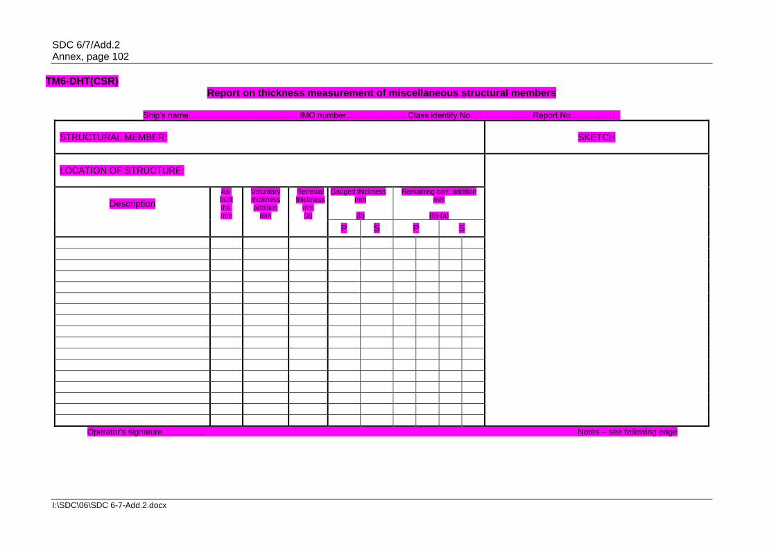
SDC 6/7/Add.2 Annex, page 102
I:\SDC\06\SDC 6-7-Add.2.docx
TM6-DHT(CSR) Report on thickness measurement of miscellaneous structural members
Ship's name…….……………..................... IMO number.......................... Class identity No.......................... Report No………………
STRUCTURAL MEMBER:
SKETCH
LOCATION OF STRUCTURE:
Description
As-built thk. mm
Voluntary thickness addition
mm
Renewal thickness
mm (a)
Gauged thickness mm
(b)
Remaining corr. addition mm
(b)-(a)
P S P S
Operator's signature.................. Notes – see following page

SDC 6/7/Add.2 Annex, page 103
I:\SDC\06\SDC 6-7-Add.2.docx
Notes to report TM6-DHT(CSR) 1 This report should be used for recording the thickness measurement of miscellaneous
structural members. 2 The single measurements recorded should represent the average of multiple
measurements. 3 The remaining corrosion addition should be recorded with result of gauged thickness
minus renewal thickness. If the result is negative, the structure in way should be renewed, and the mark "R" should be indicated in the right-hand column. If the result is between 0 and 0.5 mm (0 included), the structure in way should be additional gauged, and the mark "S" should be indicated in the right-hand column.
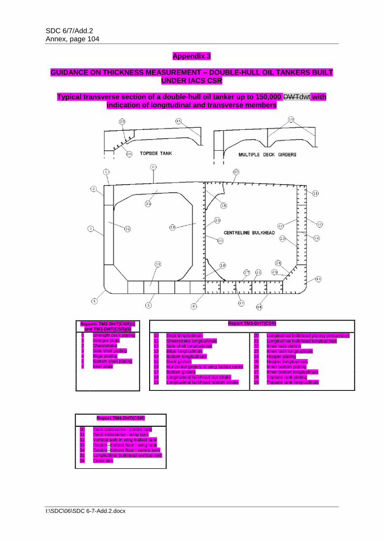
SDC 6/7/Add.2 Annex, page 104
I:\SDC\06\SDC 6-7-Add.2.docx
Appendix 3
GUIDANCE ON THICKNESS MEASUREMENT – DOUBLE-HULL OIL TANKERS BUILT UNDER IACS CSR
Typical transverse section of a double-hull oil tanker up to 150,000 DWTdwt with
indication of longitudinal and transverse members
Reports TM2-DHT(CSR)(i) and TM2-DHT(CSR)(ii)
0 Strength deck plating 1 Stringer plate 2 Sheerstrake 3 Side shell plating 4 Bilge plating 5 Bottom shell plating 6 Keel plate
Report TM3-DHT(CSR)
10 Deck longitudinals 20 Longitudinal bulkhead plating (remainder) 11 Sheerstrake longitudinals 21 Longitudinal bulkhead longitudinals 12 Side shell longitudinals 22 Inner side plating 13 Bilge longitudinals 23 Inner side longitudinals 14 Bottom longitudinals 24 Hopper plating 15 Deck girders 25 Hopper longitudinals 16 Horizontal girders in wing ballast tanks 26 Inner bottom plating 17 Bottom girders 27 Inner bottom longitudinals 18 Longitudinal bulkhead top strake 28 Topside tank plating 19 Longitudinal bulkhead bottom strake 29 Topside tank longitudinals
Report TM4-DHT(CSR)
30 Deck transverse - centre tank 31 Deck transverse - wing tank 32 Vertical web in wing ballast tank 33 Double -bottom floor - wing tank 34 Double -bottom floor - centre tank 35 Longitudinal bulkhead vertical web 36 Cross ties

SDC 6/7/Add.2 Annex, page 105
I:\SDC\06\SDC 6-7-Add.2.docx
Typical transverse section of a double -hull oil tanker above 150,000 DWTdwt with indication of longitudinal and transverse members
Report TM3-DHT(CSR)
10 Deck longitudinals 20 Longitudinal bulkhead plating (remainder) 11 Sheerstrake longitudinals 21 Longitudinal bulkhead longitudinals 12 Side shell longitudinals 22 Inner side plating 13 Bilge longitudinals 23 Inner side longitudinals 14 Bottom longitudinals 24 Hopper plating 15 Deck girders 25 Hopper longitudinals 16 Horizontal girders in wing ballast tanks 26 Inner bottom plating 17 Bottom girders 27 Inner bottom longitudinals 18 Longitudinal bulkhead top strake 28 Topside tank plating 19 Longitudinal bulkhead bottom strake 29 Topside tank longitudinals
Reports TM2-DHT(CSR)(i) and TM2-DHT(CSR)(ii)
0 Strength deck plating 1 Stringer plate 2 Sheerstrake 3 Side shell plating 4 Bilge plating 5 Bottom shell plating 6 Keel plate
Report TM4-DHT(CSR)
30 Deck transverse - centre tank 31 Deck transverse - wing tank 32 Vertical web in wing ballast tank 33 Double -bottom floor - wing tank 34 Double -bottom floor - centre tank 35 Longitudinal bulkhead vertical web 36 Cross ties

SDC 6/7/Add.2 Annex, page 106
I:\SDC\06\SDC 6-7-Add.2.docx
Transverse section outline
(This diagram may be used for those ships where the above diagrams are not suitable).
Report TM3-DHT(CSR)
10 Deck longitudinals 20 Longitudinal bulkhead plating (remainder) 11 Sheerstrake longitudinals 21 Longitudinal bulkhead longitudinals 12 Side shell longitudinals 22 Inner side plating 13 Bilge longitudinals 23 Inner side longitudinals 14 Bottom longitudinals 24 Hopper plating 15 Deck girders 25 Hopper longitudinals 16 Horizontal girders in wing ballast tanks 26 Inner bottom plating 17 Bottom girders 27 Inner bottom longitudinals 18 Longitudinal bulkhead top strake 28 Topside tank plating 19 Longitudinal bulkhead bottom strake 29 Topside tank longitudinals
Reports TM2-DHT(CSR)(i) and TM2-DHT(CSR)(ii)
0 Strength deck plating 1 Stringer plate 2 Sheerstrake 3 Side shell plating 4 Bilge plating 5 Bottom shell plating 6 Keel plate
Report TM4-DHT(CSR)
30 Deck transverse - centre tank 31 Deck transverse - wing tank 32 Vertical web in wing ballast tank 33 Double -bottom floor - wing tank 34 Double -bottom floor - centre tank 35 Longitudinal bulkhead vertical web 36 Cross ties

SDC 6/7/Add.2 Annex, page 107
I:\SDC\06\SDC 6-7-Add.2.docx
Close-up survey and thickness measurement areas
Areas subject to close-up survey and thickness measurements are - areas (1) to (5) as defined in annex 1. The thickness to be reported in forms TM3-DHT(CSR), TM4-DHT(CSR) and TM5-DHT(CSR), as appropriate.

SDC 6/7/Add.2 Annex, page 108
I:\SDC\06\SDC 6-7-Add.2.docx
Areas subject to close-up survey and thickness measurements are - areas (6) and (7) as defined in annex 1. The thickness to be reported in forms TM3-DHT(CSR) and TM4-DHT(CSR), as appropriate.
".
SDC 6/7/Add.2 Annex, page 109
I:\SDC\06\SDC 6-7-Add.2.docx
ANNEX 1112
GUIDELINES FOR TECHNICAL ASSESSMENT IN CONJUNCTION WITH THE PLANNING OF ENHANCED SURVEYS FOR OIL TANKERS*
Renewal survey
1 Introduction These Guidelines contain information and suggestions concerning technical assessments which may be of use in conjunction with the planning of renewal surveys of oil tankers. As indicated in 5.1.5, these Guidelines are a recommended tool which may be invoked at the discretion of an Administration, when considered necessary and appropriate, in conjunction with the preparation of the required survey programme. 2 Purpose and principles 2.1 Purpose The technical assessments described in these Guidelines should assist in identifying critical structural areas, nominating suspect areas and in focusing attention on structural elements or areas of structural elements which may be particularly susceptible to, or evidence a history of, wastage or damage. This information may be useful in nominating locations, areas and tanks for thickness measurement, close-up survey and tank testing. 2.2 Minimum requirements These Guidelines may not be used to reduce the requirements of annexes 1, 2 and 3 for close-up survey, thickness measurement and tank testing, respectively, which are, in all cases, to be complied with as a minimum. 2.3 Timing As with other aspects of survey planning, the technical assessments described in these Guidelines should be carried out by the owner or operator in cooperation with the Administration well in advance of the commencement of the renewal survey, i.e. prior to commencing the survey and normally at least 12 to 15 months before the survey's completion due date. 2.4 Aspects to be considered Technical assessments, which may include quantitative or qualitative evaluation of relative risks of possible deterioration, of the following aspects of a particular ship may be used as a basis for the nomination of tanks and areas for survey of:
.1 design features such as stress levels on various structural elements, design details and extent of use of high-tensile steel (HTS);
.2 former history with respect to corrosion, cracking, buckling, indents and
repairs for the particular ship as well as similar vessels, where available; and
* This annex is recommendatory.

SDC 6/7/Add.2 Annex, page 110
I:\SDC\06\SDC 6-7-Add.2.docx
.3 information with respect to types of cargo carried, use of different tanks for cargo/ballast, protection of tanks and condition of coating, if any.
Technical assessments of the relative risks of susceptibility to damage or deterioration of various structural elements and areas should be judged and decided on the basis of recognized principles and practices, such as may be found in references 1 and 2. 3 Technical assessment 3.1 General 3.1.1 There are three basic types of possible failure which may be the subject of a technical assessment in connection with the planning of surveys: corrosion, cracks and buckling. Contact damages are not normally covered by the survey plan since indents are usually noted in memoranda and assumed to be dealt with as normal routine by surveyors. 3.1.2 Technical assessments performed in conjunction with the survey planning process should, in principle, be as shown schematically in figure 1 which depicts how technical assessments can be carried out in conjunction with the survey planning process. The approach is basically an evaluation of the risk, based on the knowledge and experience related to design and corrosion. 3.1.3 The design should be considered with respect to structural details which may be susceptible to buckling or cracking as a result of vibration, high stress levels or fatigue. 3.1.4 Corrosion is related to the ageing process and is closely connected with the quality of corrosion protection at newbuilding and subsequent maintenance during the service life. Corrosion may also lead to cracking and/or buckling. 3.2 Methods 3.2.1 Design details 3.2.1.1 Damage experience related to the ship in question and similar ships, where available, are the main source of information to be used in the process of planning. In addition, a selection of structural details from the design drawings should be included. Typical damage experience to be considered will consist of:
.1 number, extent, location and frequency of cracks; and .2 location of buckles.
3.2.1.2 This information may be found in the survey reports and/or the owner's files, including the results of the owner's own inspections. The defects should be analysed, noted and marked on sketches. 3.2.1.3 In addition, general experience should be utilized. For example, reference should be made to reference 1, which contains a catalogue of typical damages and proposed repair methods for various tanker structural details. 3.2.1.4 Such figures should be used together with a review of the main drawings, in order to compare with the actual structure and search for similar details which may be susceptible to damage. An example is shown in figure 2. In particular, chapter 3 of reference 1 deals with various aspects specific to double-hull tankers, such as stress concentration locations,

SDC 6/7/Add.2 Annex, page 111
I:\SDC\06\SDC 6-7-Add.2.docx
misalignment during construction, corrosion trends, fatigue considerations and areas requiring special attention, which should be considered in working out the survey planning. 3.2.1.5 The review of the main structural drawings, in addition to using the above-mentioned figures, should include checking for typical design details where cracking has been experienced. The factors contributing to damage should be carefully considered. 3.2.1.6 The use of HTS is an important factor. Details showing good service experience where ordinary, mild steel has been used may be more susceptible to damage when HTS, and its higher associated stresses, are utilized. There is extensive and, in general, good experience, with the use of HTS for longitudinal material in deck and bottom structures. Experience in other locations, where the dynamic stresses may be higher, is less favourable, e.g. side structures. 3.2.1.7 In this respect, stress calculations of typical and important components and details, in accordance with relevant methods, may prove useful and should be considered. 3.2.1.8 The selected areas of the structure identified during this process should be recorded and marked on the structural drawings to be included in the survey programme. 3.2.2 Corrosion 3.2.2.1 In order to evaluate relative corrosion risks, the following information is generally to be considered:
.1 usage of tanks and spaces; .2 condition of coatings; .3 condition of anodes; .43 cleaning procedures; .54 previous corrosion damage; .65 ballast use and time for cargo tanks; .76 corrosion risk scheme (see reference 2, table 2.1); and .87 location of heated tanks.
3.2.2.2 Reference 2 gives definitive examples which can be used for judging and describing coating condition, using typical pictures of conditions. 3.2.2.3 The evaluation of corrosion risks should be based on information in reference 2, together with the age of the ship and relevant information on the anticipated condition of the ship as derived from the information collected in order to prepare the survey programme. 3.2.2.4 The various tanks and spaces should be listed with the corrosion risks nominated accordingly. Special attention should be given to the areas where the double-hull tanker is particularly exposed to corrosion. To this end, the specific aspects addressing corrosion in double-hull tankers indicated in 3.4 (Corrosion trends) of reference 1 should be taken into account.

SDC 6/7/Add.2 Annex, page 112
I:\SDC\06\SDC 6-7-Add.2.docx
3.2.3 Locations for close-up survey and thickness measurement 3.2.3.1 On the basis of the table of corrosion risks and the evaluation of design experience, the locations for initial close-up survey and thickness measurement (areas and sections) may be nominated. 3.2.3.2 The sections subject to thickness measurement should normally be nominated in tanks and spaces where corrosion risk is judged to be the highest. 3.2.3.3 The nomination of tanks and spaces for close-up survey should, initially, be based on highest corrosion risk and should always include ballast tanks. The principle for the selection should be that the extent is increased by age or where information is insufficient or unreliable. References 1 TSCF, Guidelines for the Inspection and Maintenance of Double Hull Tanker
Structures, 1995. 2 TSCF, Guidance Manual for Tanker Structures, 1997.

SDC 6/7/Add.2 Annex, page 113
I:\SDC\06\SDC 6-7-Add.2.docx
Figure 1 – Technical assessment and the survey planning process

SDC 6/7/Add.2 Annex, page 114
I:\SDC\06\SDC 6-7-Add.2.docx

SDC 6/7/Add.2 Annex, page 115
I:\SDC\06\SDC 6-7-Add.2.docx
Figure 2 – Typical damage and repair example (reproduced from reference 2)

SDC 6/7/Add.2 Annex, page 116
I:\SDC\06\SDC 6-7-Add.2.docx
ANNEX 1213
CRITERIA FOR LONGITUDINAL STRENGTH OF HULL GIRDER FOR OIL TANKERS* 1 General 1.1 These criteria should are to be used for the evaluation of the longitudinal strength of the ship's hull girder as required by 8.1.29.1.2. 1.2 In order that the ship's longitudinal strength to be evaluated can be recognized as valid, fillet welding between longitudinal internal members and hull envelopes should is to be in sound condition so as to keep the integrity of longitudinal internal members with hull envelopes. 2 Evaluation of longitudinal strength On oil tankers of 130 m in length and upwards and over 10 years of age, the longitudinal strength of the ship's hull girder should is to be evaluated in compliance with the requirements of this annex on the basis of the thickness measured, renewed or reinforced, as appropriate, during the renewal survey of the Cargo Ship Safety Construction Certificate or Cargo Ship Safety Certificate (SC renewal survey). The condition of the hull girder for longitudinal strength evaluation should be determined in accordance with the methods specified in appendix 3. 2.1 Calculation of transverse sectional areas of deck and bottom flanges of hull
girder 2.1.1 The transverse sectional areas of deck flange (deck plating and deck longitudinals) and bottom flange (bottom shell plating and bottom longitudinals) of the ship's hull girder should are to be calculated by using the thickness measured, renewed or reinforced, as appropriate, during the SC renewal survey. 2.1.2 If the diminution of sectional areas of either deck or bottom flange exceeds 10% of their respective as-built area (i.e. original sectional area when the ship was built), either one of the following measures should is to be taken:
.1 to renew or reinforce the deck or bottom flanges so that the actual sectional area is not less than 90% of the as-built area; or
.2 to calculate the actual section of moduli (Zact) of transverse section of
the ship's hull girder by applying the calculation method specified in appendix 1, by using the thickness measured, renewed or reinforced, as appropriate, during the SC renewal survey.
2.2 Requirements for transverse section modulus of hull girder 2.2.1 The actual section moduli of the transverse section of the ship's hull girder, calculated in accordance with 2.1.2.2, should are to satisfy either of the following provisions, as applicable:
* This annex is recommendatory.

SDC 6/7/Add.2 Annex, page 117
I:\SDC\06\SDC 6-7-Add.2.docx
.1 for ships constructed on or after 1 July 2002, the actual section moduli (Zact) of the transverse section of the ship's hull girder calculated in accordance with the requirements of paragraph 2.1.2.2 should are to be not less than the diminution limits determined by the Administration, taking into account the recommendations recommended diminution limit adopted by IMO resolution MSC.108(73) the Organization14: 90% of the required section modulus for new buildings specified in IACS' Unified Requirements S7 (C=1.0Cn is to be used for the purpose of this calculation) or S11, whichever is the greater; or
.2 for ships constructed before 1 July 2002, the actual section moduli (Zact) of
the transverse section of the ship's hull girder calculated in accordance with the requirements of 2.1.2.2 should meet the criteria for minimum section modulus for ships in service required by the Administration or recognized classification society, provided that in no case Zact should be less than the diminution limit of the minimum section modulus (Zmc) as specified in appendix 2.for ships constructed before 1 July 2002, the actual section moduli (Zact) of the transverse section of the ship's hull girder calculated in accordance with the requirements of 2.1.2.2 should are to meet the criteria for minimum section modulus for ships in service required by the Administration or recognized organization, provided that in no case Zact should is to be less than the diminution limit of the minimum section modulus (Zmc) as specified in appendix 2.
14 Refer to resolution MSC.108(73). on Recommendation on compliance with the requirements of
paragraph 2.2.1.1 of annex 12 to annex B to resolution A.744(18).

SDC 6/7/Add.2 Annex, page 118
I:\SDC\06\SDC 6-7-Add.2.docx
Appendix 1
CALCULATION CRITERIA OF SECTION MODULI OF MIDSHIP SECTION OF HULL GIRDER
1 When calculating the transverse section modulus of the ship's hull girder, the sectional area of all continuous longitudinal strength members should is to be taken into account. 2 Large openings, i.e. openings exceeding 2.5 m in length or 1.2 m in breadth, and scallops, where scallop welding is applied, are always to be deducted from the sectional areas used in the section modulus calculation. 3 Smaller openings (manholes, lightening holes, single scallops in way of seams, etc.) need not be deducted, provided that the sum of their breadths or shadow area breadths in one transverse section does not reduce the section modulus at deck or bottom by more than 3% and provided that the height of lightening holes, draining holes and single scallops in longitudinals or longitudinal girders does not exceed 25% of the web depth, for scallops maximum 75 mm. 4 A deduction-free sum of smaller opening breadths in one transverse section in the bottom or deck area of 0.06(B –Σb) (where B = breadth of ship, Σb = total breadth of large openings) may be considered equivalent to the above reduction in sectional modulus. 5 The shadow area will be obtained by drawing two tangent lines with an opening angle of 30°. 6 The deck modulus is related to the moulded deck line at side. 7 The bottom modulus is related to the baseline. 8 Continuous trunks and longitudinal hatch coamings should are to be included in the longitudinal sectional area provided they are effectively supported by longitudinal bulkheads or deep girders. The deck modulus is then to be calculated by dividing the moment of inertia by the following distance, provided this is greater than the distance to the deck line at side:
where:
y = distance from neutral axis to top of continuous strength member; x = distance from top of continuous strength member to centreline of the ship; x and y to be measured to the point giving the largest value of yt.
9 Longitudinal girders between multi-hatchways will be considered by special calculations.

SDC 6/7/Add.2 Annex, page 119
I:\SDC\06\SDC 6-7-Add.2.docx
Appendix 2
DIMINUTION LIMIT OF MINIMUM LONGITUDINAL STRENGTH OF SHIPS IN SERVICE 1 The diminution limit of the minimum section modulus (Zmc) of oil tankers in service is given by the following formula:
Zmc = cL2B(Cb + 0.7)k (cm3) where: L = Length of ships. L is the distance, in metres, on the summer load waterline from
the fore-side of stem to the after side of the rudder post, or the centre of the rudder stock if there is no rudder post. L is not to be less than 96 per cent, and need not be greater than 97%, of the extreme length on the summer load waterline. In ships with unusual stern and bow arrangement, the length L may be specially considered.
B = Greatest moulded breadth in metres. Cb = Moulded block coefficient at draught d corresponding to summer load
waterline, based on L and B. Cb is not to be taken less than 0.6.
k = material factor, e.g.
k = 1.0 for mild steel with yield stress of 235 N/mm2 and over k = 0.78 for high-tensile steel with yield stress of 315 N/mm2 and over
k = 0.72 for high-tensile steel with yield stress of 355 N/mm2 and over.
2 Scantlings of all continuous longitudinal members of the ship's hull girder based on the section modulus requirement in 1 above are to be maintained within 0.4L amidships. However, in special cases, based on consideration of type of ship, hull form and loading conditions, the scantlings may be gradually reduced towards the end of 0.4L part, bearing in mind the desire not to inhibit the ship's loading flexibility. 3 However, the above standard may not be applicable to ships of unusual type or design, e.g. for ships of unusual main proportions and/or weight distributions.
SDC 6/7/Add.2 Annex, page 120
I:\SDC\06\SDC 6-7-Add.2.docx
Appendix 3
SAMPLING METHOD OF THICKNESS MEASUREMENTS FOR LONGITUDINAL STRENGTH EVALUATION AND REPAIR METHODS
1 Extent of longitudinal strength evaluation Longitudinal strength should be evaluated within 0.4L amidships for the extent of the hull girder length that contains tanks therein and within 0.5L amidships for adjacent tanks which may extend beyond 0.4L amidships, where tanks means ballast tanks and cargo tanks. 2 Sampling method of thickness measurement 2.1 Pursuant to the requirements of section 2.5, transverse sections should be chosen such that thickness measurements can be taken for as many different tanks in corrosive environments as possible, e.g. ballast tanks sharing a common plane boundary with cargo tanks fitted with heating coils, other ballast tanks, cargo tanks permitted to be filled with seawater and other cargo tanks. Ballast tanks sharing a common plane boundary with cargo tanks fitted with heating coils and cargo tanks permitted to be filled with seawater should be selected where present. 2.2 The minimum number of transverse sections to be sampled should be in accordance with annex 2. The transverse sections should be located where the largest thickness reductions are suspected to occur or are revealed from deck and bottom plating measurements prescribed in 2.3 and should be clear of areas which have been locally renewed or reinforced. 2.3 At least two points should be measured on each deck plate and/or bottom shell plate required to be measured within the cargo area in accordance with the requirements of annex 2. 2.4 Within 0.1D (where D is the ship's moulded depth) of the deck and bottom at each transverse section to be measured in accordance with the requirements of annex 2, every longitudinal and girder should be measured on the web and face plate, and every plate should be measured at one point between longitudinals. 2.5 For longitudinal members other than those specified in 2.4 to be measured at each transverse section in accordance with the requirements of annex 2, every longitudinal and girder should be measured on the web and face plate, and every plate should be measured at least in one point per strake. 2.6 The thickness of each component should be determined by averaging all of the measurements taken in way of the transverse section on each component. 3 Additional measurements where the longitudinal strength is deficient 3.1 Where one or more of the transverse sections are found to be deficient in respect of the longitudinal strength requirements given in this annex, the number of transverse sections for thickness measurement should be increased such that each tank within the 0.5L amidships region has been sampled. Tank spaces that are partially within, but extend beyond, the 0.5L region, should be sampled. 3.2 Additional thickness measurements should also be performed on one transverse section forward and one aft of each repaired area to the extent necessary to ensure that the areas bordering the repaired section also comply with the requirements of the Code.

SDC 6/7/Add.2 Annex, page 121
I:\SDC\06\SDC 6-7-Add.2.docx
4 Effective repair methods 4.1 The extent of renewal or reinforcement carried out to comply with this annex should be in accordance with 4.2. 4.2 The minimum continuous length of a renewed or reinforced structural member should be not less than twice the spacing of the primary members in way. In addition, the thickness diminution in way of the butt joint of each joining member forward and aft of the replaced member (plates, stiffeners, girder webs and flanges, etc.) should not be within the substantial corrosion range (75% of the allowable diminution associated with each particular member). Where differences in thickness at the butt joint exceed 15% of the lower thickness, a transition taper should be provided. 4.3 Alternative repair methods involving the fitting of straps or structural member modification should be subject to special consideration. In considering the fitting of straps, it should be limited to the following conditions:
.1 to restore and/or increase longitudinal strength; .2 the thickness diminution of the deck or bottom plating to be reinforced should
not be within the substantial corrosion range (75% of the allowable diminution associated with the deck plating);
.3 the alignment and arrangement, including the termination of the straps, is in
accordance with a standard recognized by the Administration; .4 the straps are continuous over the entire 0.5L amidships length; and .5 continuous fillet welding and full penetration welds are used at butt welding
and, depending on the width of the strap, slot welds. The welding procedures applied should be acceptable to the Administration.
4.4 The existing structure adjacent to replacement areas and in conjunction with the fitted straps, etc., should be capable of withstanding the applied loads, taking into account the buckling resistance and the condition of welds between the longitudinal members and hull envelope plating.

SDC 6/7/Add.2 Annex, page 122
I:\SDC\06\SDC 6-7-Add.2.docx
ANNEX 14
PROCEDURAL REQUIREMENTS FOR THICKNESS MEASUREMENTS
1 General Thickness measurements required in the context of hull structural surveys, if not carried out by the recognized organization acting on behalf of the Administration, shall be witnessed by a surveyor of the recognized organization. The attendance of the surveyor shall be recorded. This also applies to thickness measurements taken during voyages. 2 Survey meeting 2.1 Prior to commencement of the renewal or intermediate survey, a meeting is to be held between the attending surveyor(s), the master of the ship or an appropriately qualified representative appointed by the master or company, the owner's representative(s) in attendance and the thickness measurement firm's representative(s) so as to ensure the safe and efficient execution of the surveys and thickness measurements to be carried out on board. 2.2 Communication with the thickness measurement operator(s) and owner's representative(s) shall be agreed during the meeting, with respect to the following:
.1 reporting of thickness measurements on a regular basis to the attending surveyor; and
.2 prompt notification to the surveyor in case of findings such as:
.1 excessive and/or extensive corrosion or pitting/grooving of any significance;
.2 structural defects like buckling, fractures and deformed structures; .3 detached and/or holed structure; and .4 corrosion of welds.
2.3 When thickness measurements are taken in association with intermediate or renewal surveys, a documented record indicating where and when the meeting took place and who attended (the name of the surveyor(s), the master of the ship or an appropriately qualified representative appointed by the master or company, the owner's representative(s) and the representative(s) of the thickness measurement firm(s)) is to be maintained. 3 Monitoring of the thickness measurement process on board 3.1 The surveyor shall decide final extent and location of thickness measurements after overall survey of representative spaces on board. 3.2 In case the owner prefers to commence the thickness measurements prior to the overall survey, then the surveyor shall advise that the planned extent and locations of thickness measurements are subject to confirmation during the overall survey. Based on findings, the surveyor may require additional thickness measurements to be taken.

SDC 6/7/Add.2 Annex, page 123
I:\SDC\06\SDC 6-7-Add.2.docx
3.3 The surveyor shall direct the gauging operation by selecting locations such that readings taken represent, on average, the condition of the structure for that area. 3.4 Thickness measurements taken mainly to evaluate the extent of corrosion, which may affect the hull girder strength, shall be carried out in a systematic manner such that all longitudinal structural members are gauged, as required. 3.5 Where thickness measurements indicate substantial corrosion or wastage in excess of allowable diminution, the surveyor shall direct locations for additional thickness measurements in order to delineate areas of substantial corrosion and to identify structural members for repairs/renewals. 3.6 Thickness measurements of structures in areas where close-up surveys are required shall be carried out simultaneously with close-up survey. 4 Review and verification 4.1 Upon completion of the thickness measurements, the surveyor shall confirm that no further gaugings are needed, or specify additional gaugings. 4.2 If, where special consideration is allowed by this Code, the extent of thickness measurements is reduced, the surveyor's special consideration is to be reported. 4.3 In case thickness measurements are partly carried out, the extent of remaining thickness measurements shall be reported for the use of the next surveyor.
___________