Sub Code: CS1251 - book1478965436987456.yolasite.com/resources/Kinematics of Machinery.pdf ·...
64
Sub Code: ME35 Page 2 of 65 ©Einstein College of Engineering Lecture plan UNIT I Basics of Mechanisms SYLLABUS Introduction: Definitions : Link or Element, Pairing of Elements with degrees of freedom, Grubler’s criterion (without derivation), Kinematic chain, Mechanism, Mobility of Mechanism, Inversions, Machine. Kinematic Chains and Inversions : Kinematic chain with three lower pairs, Four bar chain, Single slider crank chain and Double slider crank chain and their inversions. Mechanisms: 1. Quick returns motion mechanisms – Drag link mechanism, Whitworth mechanism and Crank and slotted lever mechanism 2. Straight line motion mechanisms – Peacelier’s mechanism and Robert’s mechanism. 3. Intermittent motion mechanisms – Geneva mechanism and Ratchet & Pawl mechanism. 4. Toggle mechanism, Pantograph, Hooke’s joint and Ackerman Steering gear mechanism. What is Kinematics? Kinematics is the study of motion (position, velocity, acceleration). A major goal of understanding kinematics is to develop the ability to design a system that will satisfy specified motion requirements. This will be the emphasis of this class. What is Kinetics? Kinetics is the study of effect of forces on moving bodies. Good kinematic design should produce good kinetics. Definitions Link: A link is defined as a member or a combination of members of a mechanism connecting other members and having relative motion between them. The link may consist of one or more resistant bodies. A link may be called as kinematic link or element. Eg: Reciprocating steam engine. www.eeeexclusive.blogspot.com
Transcript of Sub Code: CS1251 - book1478965436987456.yolasite.com/resources/Kinematics of Machinery.pdf ·...

Sub Code: ME35
Page 2 of 65
©Einstein College of Engineering
Lecture plan
UNIT I Basics of Mechanisms
SYLLABUS
Introduction:
Definitions : Link or Element, Pairing of Elements with degrees of freedom, Grubler’s
criterion (without derivation), Kinematic chain, Mechanism, Mobility of Mechanism,
Inversions, Machine.
Kinematic Chains and Inversions :
Kinematic chain with three lower pairs, Four bar chain, Single slider crank chain and
Double slider crank chain and their inversions.
Mechanisms:
1. Quick returns motion mechanisms – Drag link mechanism, Whitworth mechanism
and Crank and slotted lever mechanism
2. Straight line motion mechanisms – Peacelier’s mechanism and Robert’s
mechanism.
3. Intermittent motion mechanisms – Geneva mechanism and Ratchet & Pawl
mechanism.
4. Toggle mechanism, Pantograph, Hooke’s joint and Ackerman Steering gear
mechanism.
What is Kinematics?
Kinematics is the study of motion (position, velocity, acceleration). A major goal of
understanding kinematics is to develop the ability to design a system that will satisfy
specified motion requirements. This will be the emphasis of this class.
What is Kinetics?
Kinetics is the study of effect of forces on moving bodies. Good kinematic design should
produce good kinetics.
Definitions
Link:
A link is defined as a member or a combination of members of a mechanism connecting other
members and having relative motion between them. The link may consist of one or more
resistant bodies. A link may be called as kinematic link or element. Eg: Reciprocating steam
engine.
www.eeee
xclus
ive.bl
ogsp
ot.co
m

Sub Code: ME35
Page 3 of 65
©Einstein College of Engineering
Classification of link is binary, ternary and quarternary.
Joint: A connection between two links that allows motion between the links. The motion
allowed may be rotational (revolute joint), translational (sliding or prismatic joint), or a
combination of the two (roll-slide joint).
Kinematic pair:
Kinematic pair is a joint of two links having relative motion between them. The types of
kinematic pair are classified according to
Nature of contact ( lower pair, Higher pair)
Nature of mechanical contact ( Closed pair, unclosed pair)
Nature of relative motion ( Sliding pair, turning pair, rolling pair, screw pair, spherical
pair)
In the above given Slider crank mechanism, link 2 rotates relative to link 1 and constitutes a
revolute or turning pair. Similarly, links 2, 3 and 3, 4 constitute turning pairs. Link 4 (Slider)
reciprocates relative to link 1 and its a sliding pair.
www.eeee
xclus
ive.bl
ogsp
ot.co
m
Sub Code: ME35
Page 4 of 65
©Einstein College of Engineering
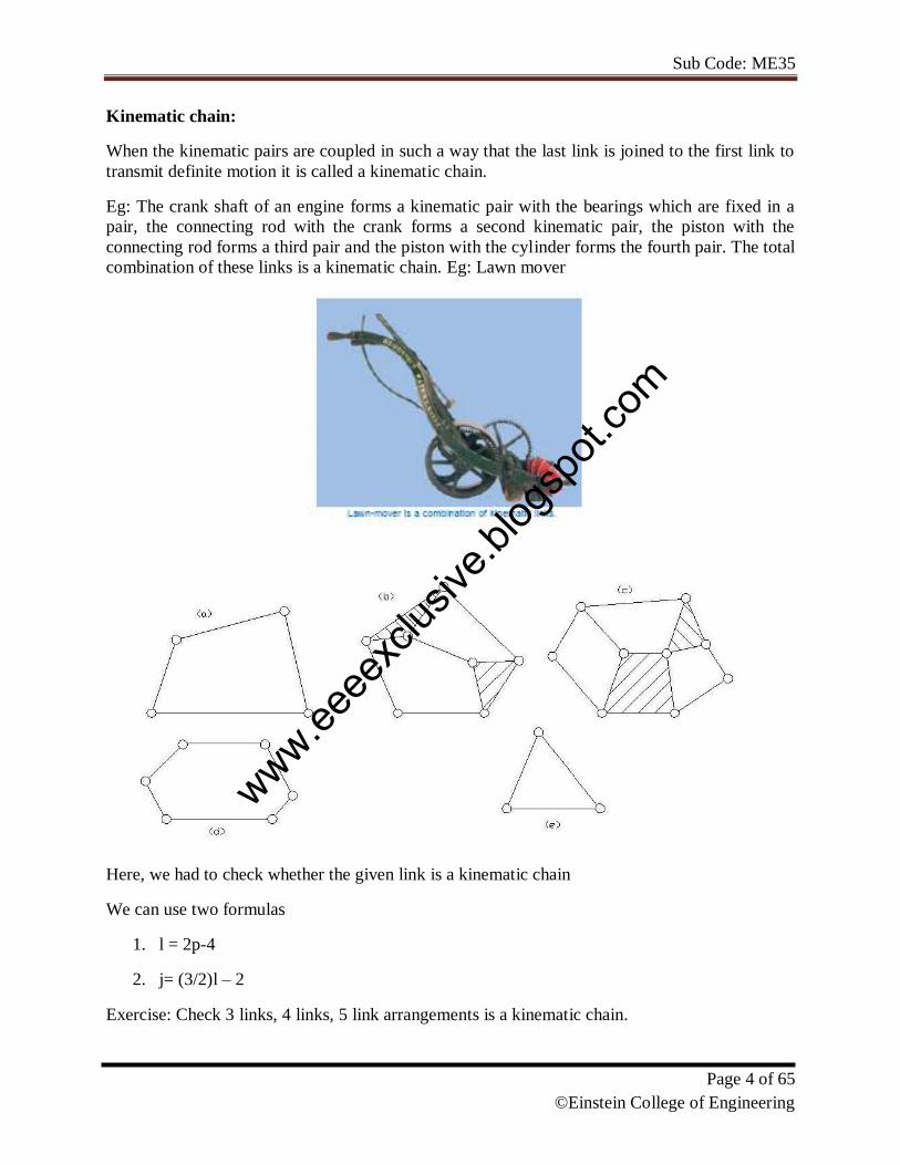
Kinematic chain:
When the kinematic pairs are coupled in such a way that the last link is joined to the first link to
transmit definite motion it is called a kinematic chain.
Eg: The crank shaft of an engine forms a kinematic pair with the bearings which are fixed in a
pair, the connecting rod with the crank forms a second kinematic pair, the piston with the
connecting rod forms a third pair and the piston with the cylinder forms the fourth pair. The total
combination of these links is a kinematic chain. Eg: Lawn mover
Here, we had to check whether the given link is a kinematic chain
We can use two formulas
1. l = 2p-4
2. j= (3/2)l – 2
Exercise: Check 3 links, 4 links, 5 link arrangements is a kinematic chain.
www.eeee
xclus
ive.bl
ogsp
ot.co
m
Sub Code: ME35
Page 5 of 65
©Einstein College of Engineering
Mechanism
If motion of any of the movable links results in definite motions of the others the linkage is
known as mechanism
Machine
When a mechanism is required to transmit power or to do some particular type of work it then
becomes a machine.
Degrees of Freedom
It is defined as the number of input parameters which must be independently controlled in order
to bring the mechanism in to useful engineering purposes.
It is also defined as the number of independent relative motions, both translational and rotational,
a pair can have.
Degrees of freedom = 6 – no. of restraints.
To find the number of degrees of freedom for a plane mechanism we have Grubler’s equation
F = 3 (n – 1) – 2 j1 – j2
F = Mobility or number of degrees of freedom
n = Number of links including frame.
j1 = Joints with single (one) degree of freedom.
J2 = Joints with two degrees of freedom.
F > 0, results in a mechanism with ‘F’ degrees of freedom.
F = 0, results in a statically determinate structure.
F < 0, results in a statically indeterminate structure.
MOBILITY- Kutzbach criterion, Grashoff's law
Mobility: Kutzbach criterion:
Fundamental Equation for 2-D Mechanisms: M = 3(L – 1) – 2J1 – J2
Here we solve, the following problems
www.eeee
xclus
ive.bl
ogsp
ot.co
m
Sub Code: ME35
Page 6 of 65
©Einstein College of Engineering
If you pin one end of the link to the plane, how many degrees of freedom does it now
have?
Add a second link to the picture so that you have one link pinned to the plane and one
free to move in the plane. How many degrees of freedom exist between the two links? (4
is the correct answer)
Pin the second link to the free end of the first link. How many degrees of freedom do you
now have?
How many degrees of freedom do you have each time you introduce a moving link?
How many degrees of freedom do you take away when you add a simple joint? How
many degrees of freedom would you take away by adding a half joint? Do the different
terms in equation make sense in light of this knowledge?
Here we would also calculate the following:
1. Number of binary links
2. Number of ternary links
3. The number of quaternary links
4. number of loops
5. number of joints or pairs
6. the number of degrees of freedom
7. Stating whether the given linkages are mechanisms with one degree of freedom.
Grashoff's law:
Grashoff 4-bar linkage: A linkage that contains one or more links capable of undergoing a full rotation.
A linkage is Grashoff if: S + L < P + Q
(Where: S = shortest link length, L = longest, P, Q = intermediate length links).
Both joints of the shortest link are capable of 360 degrees of rotation in a Grashoff
linkages.
This gives us 4 possible linkages:
crank-rocker (input rotates 360
rocker-crank-rocker (coupler rotates 360)
rocker-crank (follower)
double crank (all links rotate 360).
www.eeee
xclus
ive.bl
ogsp
ot.co
m
Sub Code: ME35
Page 7 of 65
©Einstein College of Engineering
Problems:
We can also calculate how many unique mechanisms can be obtained from the 8- link
kinematic chain.
We can also calculate degree of freedom and the number of ternary and quaternary links
it will have if it has only single turning pairs.
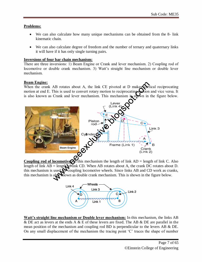
Inversions of four bar chain mechanism: There are three inversions: 1) Beam Engine or Crank and lever mechanism. 2) Coupling rod of
locomotive or double crank mechanism. 3) Watt’s straight line mechanism or double lever
mechanism.
Beam Engine:
When the crank AB rotates about A, the link CE pivoted at D makes vertical reciprocating
motion at end E. This is used to convert rotary motion to reciprocating motion and vice versa. It
is also known as Crank and lever mechanism. This mechanism is shown in the figure below.
Coupling rod of locomotive: In this mechanism the length of link AD = length of link C. Also
length of link AB = length of link CD. When AB rotates about A, the crank DC rotates about D.
this mechanism is used for coupling locomotive wheels. Since links AB and CD work as cranks,
this mechanism is also known as double crank mechanism. This is shown in the figure below.
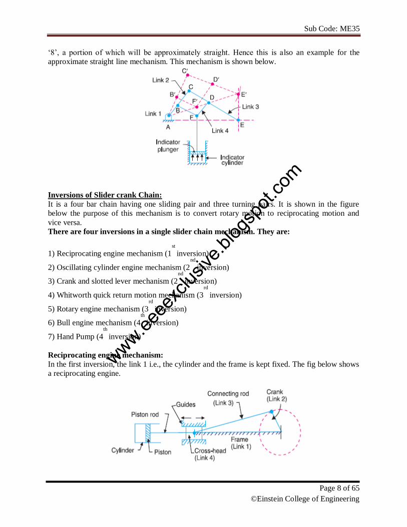
Watt’s straight line mechanism or Double lever mechanism: In this mechanism, the links AB
& DE act as levers at the ends A & E of these levers are fixed. The AB & DE are parallel in the
mean position of the mechanism and coupling rod BD is perpendicular to the levers AB & DE.
On any small displacement of the mechanism the tracing point ‘C’ traces the shape of number
www.eeee
xclus
ive.bl
ogsp
ot.co
m
Sub Code: ME35
Page 8 of 65
©Einstein College of Engineering
‘8’, a portion of which will be approximately straight. Hence this is also an example for the
approximate straight line mechanism. This mechanism is shown below.
Inversions of Slider crank Chain:
It is a four bar chain having one sliding pair and three turning pairs. It is shown in the figure
below the purpose of this mechanism is to convert rotary motion to reciprocating motion and
vice versa.
There are four inversions in a single slider chain mechanism. They are:
1) Reciprocating engine mechanism (1st
inversion)
2) Oscillating cylinder engine mechanism (2nd
inversion)
3) Crank and slotted lever mechanism (2nd
inversion)
4) Whitworth quick return motion mechanism (3rd
inversion)
5) Rotary engine mechanism (3rd
inversion)
6) Bull engine mechanism (4th
inversion)
7) Hand Pump (4th
inversion)
Reciprocating engine mechanism:
In the first inversion, the link 1 i.e., the cylinder and the frame is kept fixed. The fig below shows
a reciprocating engine.
www.eeee
xclus
ive.bl
ogsp
ot.co
m
Sub Code: ME35
Page 9 of 65
©Einstein College of Engineering
A slotted link 1 is fixed. When the crank 2 rotates about O, the sliding piston 4 reciprocates in
the slotted link 1. This mechanism is used in steam engine, pumps, compressors, I.C. engines,
etc.
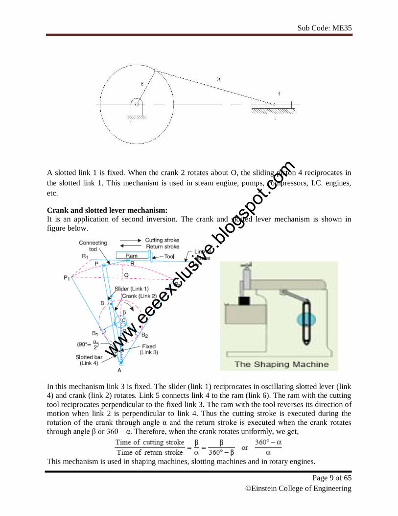
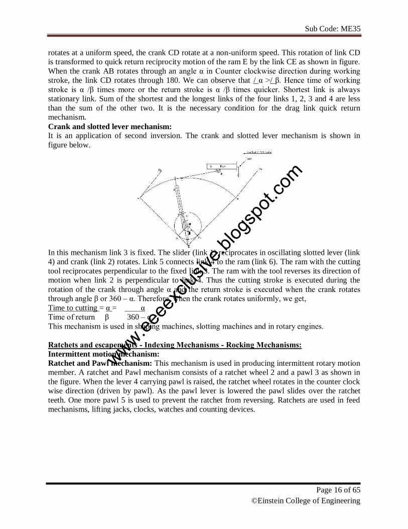
Crank and slotted lever mechanism:
It is an application of second inversion. The crank and slotted lever mechanism is shown in
figure below.
In this mechanism link 3 is fixed. The slider (link 1) reciprocates in oscillating slotted lever (link
4) and crank (link 2) rotates. Link 5 connects link 4 to the ram (link 6). The ram with the cutting
tool reciprocates perpendicular to the fixed link 3. The ram with the tool reverses its direction of
motion when link 2 is perpendicular to link 4. Thus the cutting stroke is executed during the
rotation of the crank through angle α and the return stroke is executed when the crank rotates
through angle β or 360 – α. Therefore, when the crank rotates uniformly, we get,
This mechanism is used in shaping machines, slotting machines and in rotary engines.
www.eeee
xclus
ive.bl
ogsp
ot.co
m
Sub Code: ME35
Page 10 of 65
©Einstein College of Engineering
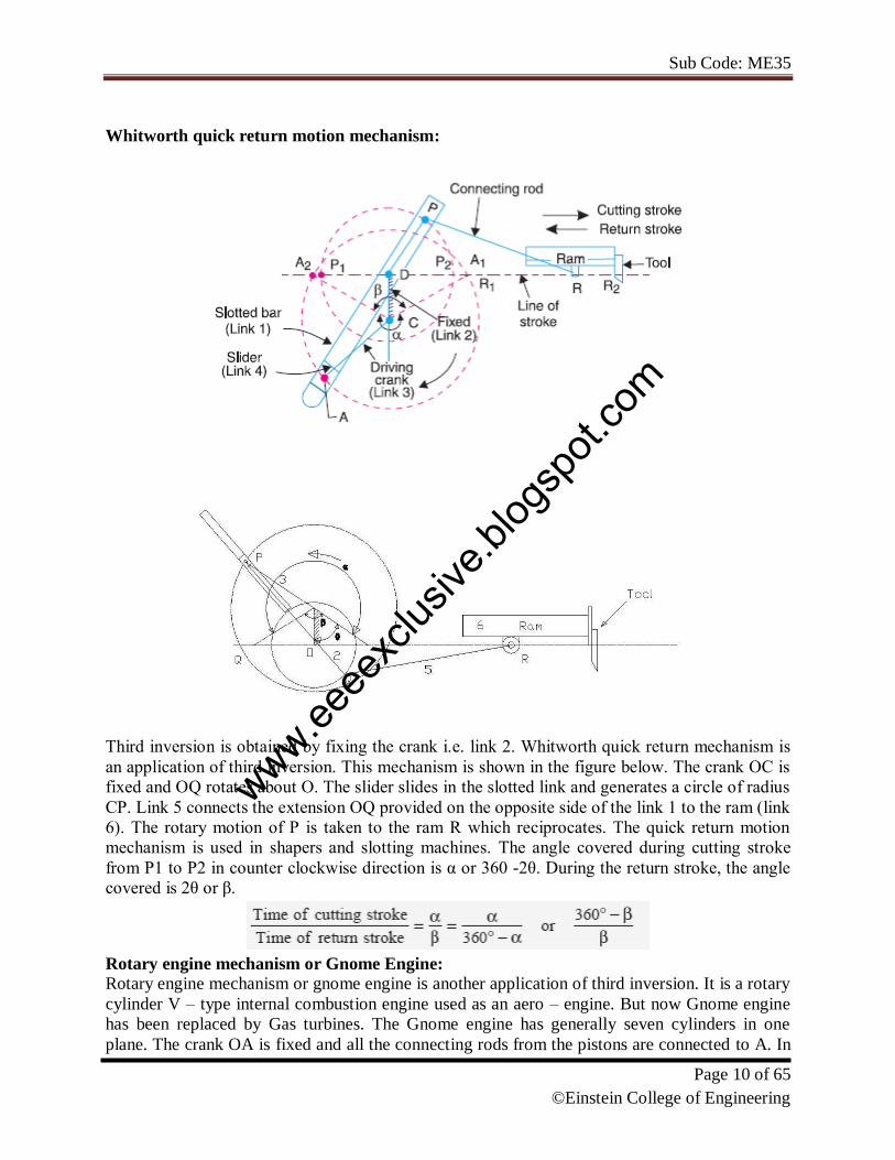
Whitworth quick return motion mechanism:
Third inversion is obtained by fixing the crank i.e. link 2. Whitworth quick return mechanism is
an application of third inversion. This mechanism is shown in the figure below. The crank OC is
fixed and OQ rotates about O. The slider slides in the slotted link and generates a circle of radius
CP. Link 5 connects the extension OQ provided on the opposite side of the link 1 to the ram (link
6). The rotary motion of P is taken to the ram R which reciprocates. The quick return motion
mechanism is used in shapers and slotting machines. The angle covered during cutting stroke
from P1 to P2 in counter clockwise direction is α or 360 -2θ. During the return stroke, the angle
covered is 2θ or β.
Rotary engine mechanism or Gnome Engine:
Rotary engine mechanism or gnome engine is another application of third inversion. It is a rotary
cylinder V – type internal combustion engine used as an aero – engine. But now Gnome engine
has been replaced by Gas turbines. The Gnome engine has generally seven cylinders in one
plane. The crank OA is fixed and all the connecting rods from the pistons are connected to A. In
www.eeee
xclus
ive.bl
ogsp
ot.co
m

Sub Code: ME35
Page 11 of 65
©Einstein College of Engineering
this mechanism when the pistons reciprocate in the cylinders, the whole assembly of cylinders,
pistons and connecting rods rotate about the axis O, where the entire mechanical power
developed, is obtained in the form of rotation of the crank shaft. This mechanism is shown in the
figure below.
Double Slider Crank Chain: A four bar chain having two turning and two sliding pairs such that two pairs of the same kind
are adjacent is known as double slider crank chain.
Inversions of Double slider Crank chain:
It consists of two sliding pairs and two turning pairs. There are three important inversions of
double slider crank chain. 1) Elliptical trammel. 2) Scotch yoke mechanism. 3) Oldham’s
Coupling.
Elliptical Trammel:
This is an instrument for drawing ellipses. Here the slotted link is fixed. The sliding block P and
Q in vertical and horizontal slots respectively. The end R generates an ellipse with the
displacement of sliders P and Q.
www.eeee
xclus
ive.bl
ogsp
ot.co
m
Sub Code: ME35
Page 12 of 65
©Einstein College of Engineering
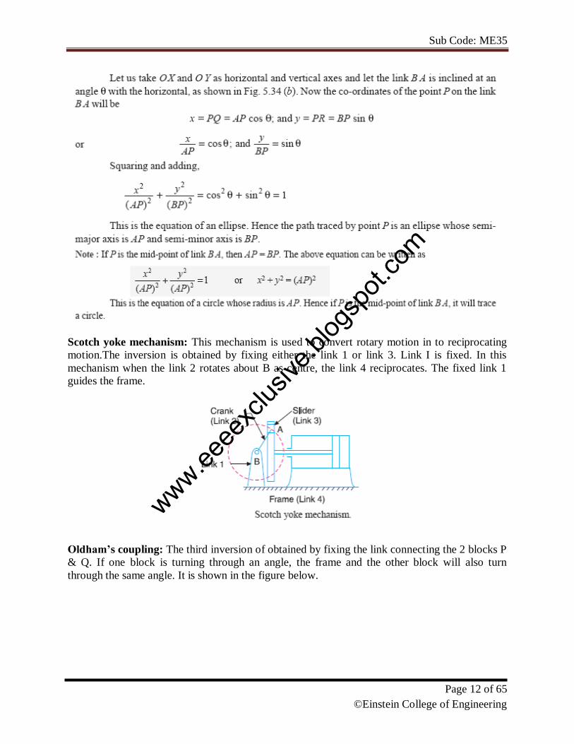
Scotch yoke mechanism: This mechanism is used to convert rotary motion in to reciprocating
motion.The inversion is obtained by fixing either the link 1 or link 3. Link I is fixed. In this
mechanism when the link 2 rotates about B as centre, the link 4 reciprocates. The fixed link 1
guides the frame.
Oldham’s coupling: The third inversion of obtained by fixing the link connecting the 2 blocks P
& Q. If one block is turning through an angle, the frame and the other block will also turn
through the same angle. It is shown in the figure below.
www.eeee
xclus
ive.bl
ogsp
ot.co
m
Sub Code: ME35
Page 13 of 65
©Einstein College of Engineering
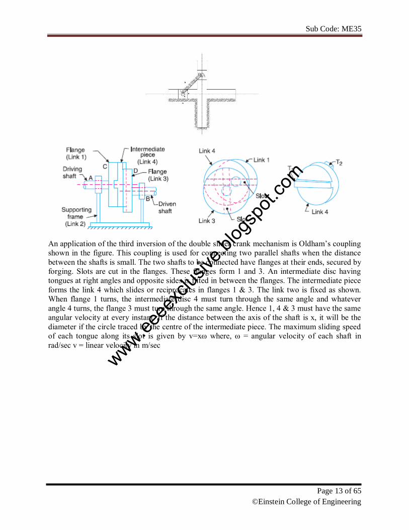
An application of the third inversion of the double slider crank mechanism is Oldham’s coupling
shown in the figure. This coupling is used for connecting two parallel shafts when the distance
between the shafts is small. The two shafts to be connected have flanges at their ends, secured by
forging. Slots are cut in the flanges. These flanges form 1 and 3. An intermediate disc having
tongues at right angles and opposite sides is fitted in between the flanges. The intermediate piece
forms the link 4 which slides or reciprocates in flanges 1 & 3. The link two is fixed as shown.
When flange 1 turns, the intermediate disc 4 must turn through the same angle and whatever
angle 4 turns, the flange 3 must turn through the same angle. Hence 1, 4 & 3 must have the same
angular velocity at every instant. If the distance between the axis of the shaft is x, it will be the
diameter if the circle traced by the centre of the intermediate piece. The maximum sliding speed
of each tongue along its slot is given by v=xω where, ω = angular velocity of each shaft in
rad/sec v = linear velocity in m/sec
www.eeee
xclus
ive.bl
ogsp
ot.co
m

Sub Code: ME35
Page 14 of 65
©Einstein College of Engineering
Mechanical Advantage, Transmission angle:
The mechanical advantage (MA) is defined as the ratio of output torque to the input
torque. (Or) ratio of load to output.
Transmission angle.
The extreme values of the transmission angle occur when the crank lies along the line of
frame.
www.eeee
xclus
ive.bl
ogsp
ot.co
m

Sub Code: ME35
Page 15 of 65
©Einstein College of Engineering
common mechanisms-Single, Double and offset slider mechanisms - Quick return
mechanisms:
Quick Return Motion Mechanisms:
Many times mechanisms are designed to perform repetitive operations. During these operations
for a certain period the mechanisms will be under load known as working stroke and the
remaining period is known as the return stroke, the mechanism returns to repeat the operation
without load. The ratio of time of working stroke to that of the return stroke is known a time
ratio. Quick return mechanisms are used in machine tools to give a slow cutting stroke and a
quick return stroke. The various quick return mechanisms commonly used are i) Whitworth ii)
Drag link. iii) Crank and slotted lever mechanism.
Whitworth quick return mechanism: Whitworth quick return mechanism is an application of third inversion of the single slider crank
chain. This mechanism is shown in the figure below. The crank OC is fixed and OQ rotates
about O. The slider slides in the slotted link and generates a circle of radius CP. Link 5 connects
the extension OQ provided on the opposite side of the link 1 to the ram (link 6). The rotary
motion of P is taken to the ram R which reciprocates. The quick return motion mechanism is
used in shapers and slotting machines.
The angle covered during cutting stroke from P1 to P2 in counter clockwise direction is α or 360
-2θ. During the return stroke, the angle covered is 2θ or β.
Drag link mechanism:
This is four bar mechanism with double crank in which the shortest link is fixed. If the crank AB
www.eeee
xclus
ive.bl
ogsp
ot.co
m
Sub Code: ME35
Page 16 of 65
©Einstein College of Engineering
rotates at a uniform speed, the crank CD rotate at a non-uniform speed. This rotation of link CD
is transformed to quick return reciprocity motion of the ram E by the link CE as shown in figure.
When the crank AB rotates through an angle α in Counter clockwise direction during working
stroke, the link CD rotates through 180. We can observe that / α >/ β. Hence time of working
stroke is α /β times more or the return stroke is α /β times quicker. Shortest link is always
stationary link. Sum of the shortest and the longest links of the four links 1, 2, 3 and 4 are less
than the sum of the other two. It is the necessary condition for the drag link quick return
mechanism.
Crank and slotted lever mechanism:
It is an application of second inversion. The crank and slotted lever mechanism is shown in
figure below.
In this mechanism link 3 is fixed. The slider (link 1) reciprocates in oscillating slotted lever (link
4) and crank (link 2) rotates. Link 5 connects link 4 to the ram (link 6). The ram with the cutting
tool reciprocates perpendicular to the fixed link 3. The ram with the tool reverses its direction of
motion when link 2 is perpendicular to link 4. Thus the cutting stroke is executed during the
rotation of the crank through angle α and the return stroke is executed when the crank rotates
through angle β or 360 – α. Therefore, when the crank rotates uniformly, we get,
Time to cutting = α = α
Time of return β 360 – α
This mechanism is used in shaping machines, slotting machines and in rotary engines.
Ratchets and escapements - Indexing Mechanisms - Rocking Mechanisms:
Intermittent motion mechanism:
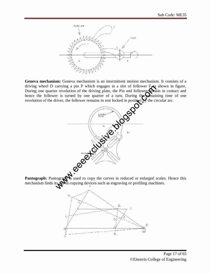
Ratchet and Pawl mechanism: This mechanism is used in producing intermittent rotary motion
member. A ratchet and Pawl mechanism consists of a ratchet wheel 2 and a pawl 3 as shown in
the figure. When the lever 4 carrying pawl is raised, the ratchet wheel rotates in the counter clock
wise direction (driven by pawl). As the pawl lever is lowered the pawl slides over the ratchet
teeth. One more pawl 5 is used to prevent the ratchet from reversing. Ratchets are used in feed
mechanisms, lifting jacks, clocks, watches and counting devices.
www.eeee
xclus
ive.bl
ogsp
ot.co
m
Sub Code: ME35
Page 17 of 65
©Einstein College of Engineering
Geneva mechanism: Geneva mechanism is an intermittent motion mechanism. It consists of a
driving wheel D carrying a pin P which engages in a slot of follower F as shown in figure.
During one quarter revolution of the driving plate, the Pin and follower remain in contact and
hence the follower is turned by one quarter of a turn. During the remaining time of one
revolution of the driver, the follower remains in rest locked in position by the circular arc.
Pantograph: Pantograph is used to copy the curves in reduced or enlarged scales. Hence this
mechanism finds its use in copying devices such as engraving or profiling machines.
www.eeee
xclus
ive.bl
ogsp
ot.co
m

Sub Code: ME35
Page 18 of 65
©Einstein College of Engineering
This is a simple figure of a Pantograph. The links are pin jointed at A, B, C and D. AB is parallel
to DC and AD is parallel to BC. Link BA is extended to fixed pin O. Q is a point on the link AD.
If the motion of Q is to be enlarged then the link BC is extended to P such that O, Q and P are in
a straight line. Then it can be shown that the points P and Q always move parallel and similar to
each other over any path straight or curved. Their motions will be proportional to their distance
from the fixed point. Let ABCD be the initial position. Suppose if point Q moves to Q1 , then all
the links and the joints will move to the new positions (such as A moves to A1 , B moves to Q1,
C moves to Q1 , D moves to D1 and P to P1 ) and the new configuration of the mechanism is
shown by dotted lines. The movement of Q (Q Q1) will be enlarged to PP1 in a definite ratio.
Toggle Mechanism:
In slider crank mechanism as the crank approaches one of its dead centre position, the slider
approaches zero. The ratio of the crank movement to the slider movement approaching infinity is
proportional to the mechanical advantage. This is the principle used in toggle mechanism. A
toggle mechanism is used when large forces act through a short distance is required. The figure
below shows a toggle mechanism. Links CD and CE are of same length. Resolving the forces at
C vertically F Sin α =P Cos α 2
Therefore, F = P. (because Sin α/Cos α = Tan α) 2 tan α Thus for the given value of P, as the
links CD and CE approaches collinear position (αO), the force F rises rapidly.
Hooke’s joint:
Hooke’s joint used to connect two parallel intersecting shafts as shown in figure. This can also
be used for shaft with angular misalignment where flexible coupling does not serve the purpose.
Hence Hooke’s joint is a means of connecting two rotating shafts whose axes lie in the same
www.eeee
xclus
ive.bl
ogsp
ot.co
m

Sub Code: ME35
Page 19 of 65
©Einstein College of Engineering
plane and their directions making a small angle with each other. It is commonly known as
Universal joint. In Europe it is called as Cardan joint.
5. Ackermann steering gear mechanism:
This mechanism is made of only turning pairs and is made of only turning pairs wear and tear of
the parts is less and cheaper in manufacturing. The cross link KL connects two short axles AC
and BD of the front wheels through the short links AK and BL which forms bell crank levers
CAK and DBL respectively as shown in fig, the longer links AB and KL are parallel and the
shorter links AK and BL are inclined at an angle α. When the vehicles steer to the right as shown
in the figure, the short link BL is turned so as to increase α, where as the link LK causes the other
short link AK to turn so as to reduce α. The fundamental equation for correct steering is, CotΦ–
Cosθ = b / l. In the above arrangement it is clear that the angle Φ through which AK turns is less
than the angle θ through which the BL turns and therefore the left front axle turns through a
smaller angle than the right front axle. For different angle of turn θ, the corresponding value of Φ
and (Cot Φ – Cos θ) are noted. This is done by actually drawing the mechanism to a scale or by
calculations. Therefore for different value of the corresponding value of and are tabulated.
Approximate value of b/l for correct steering should be between 0.4 and 0.5. In an Ackermann
steering gear mechanism, the instantaneous centre I does not lie on the axis of the rear axle but
on a line parallel to the rear axle axis at an approximate distance of 0.3l above it.
Question Bank- I unit
Important Two marks
Define resistant body.
Define Link or Element
Differentiate Machine and Structure
Define Kinematic Pair.
Define Kinematic Chain.
What are the types of joints?
Define Degrees of Freedom (Mobility).
Write down the Kutzbach criterion for plane mechanism.
What is meant by spatial mechanism?
Differentiate Machine and Mechanism.
Define Inversion of Mechanism
www.eeee
xclus
ive.bl
ogsp
ot.co
m
Sub Code: ME35
Page 20 of 65
©Einstein College of Engineering
Define Grashof’s Law.
Define Pantograph.
What is Elliptical Trammel?
Define Transmission Angle and Mechanical Advantage
What is a straight line Mechanism?
Important Descriptive University questions:
Explain different types of Link.
Classify and explain the Kinematic pair.
Explain any two inversion of four bar chain.
Explain the first inversion of Single Slider Crank Chain.
Explain first inversion of Double Slider crank chain.
Explain third inversion of double slider crank chain.
Explain the offset slider crank mechanism.
Explain Straight line mechanism with neat sketch.
With the help of a neat sketch explain the working of Oldham’s coupling.
Explain steering gear mechanism with neat sketch.
With the help of a neat sketch explain the working of Whitworth quick return mechanism.
With the help of a neat sketch explain the working of Single slider and double slider crank chain mechanism.
References
1. Ambekar A. G., Mechanism and Machine Theory, Prentice Hall of India, New Delhi, 2007.
2. Khurmi R.S., Gupta J.K., Theory of machines, S. Chand company limited, New Delhi, 2009.
Web site:
www. nptel.iitm.ac.in (National programme on technology enhanced learning by IIT, India)
http://www.scribd.com/doc/18424291/Kinematics-of-Machines
www.eeee
xclus
ive.bl
ogsp
ot.co
m
Sub Code: ME35
Page 21 of 65
©Einstein College of Engineering
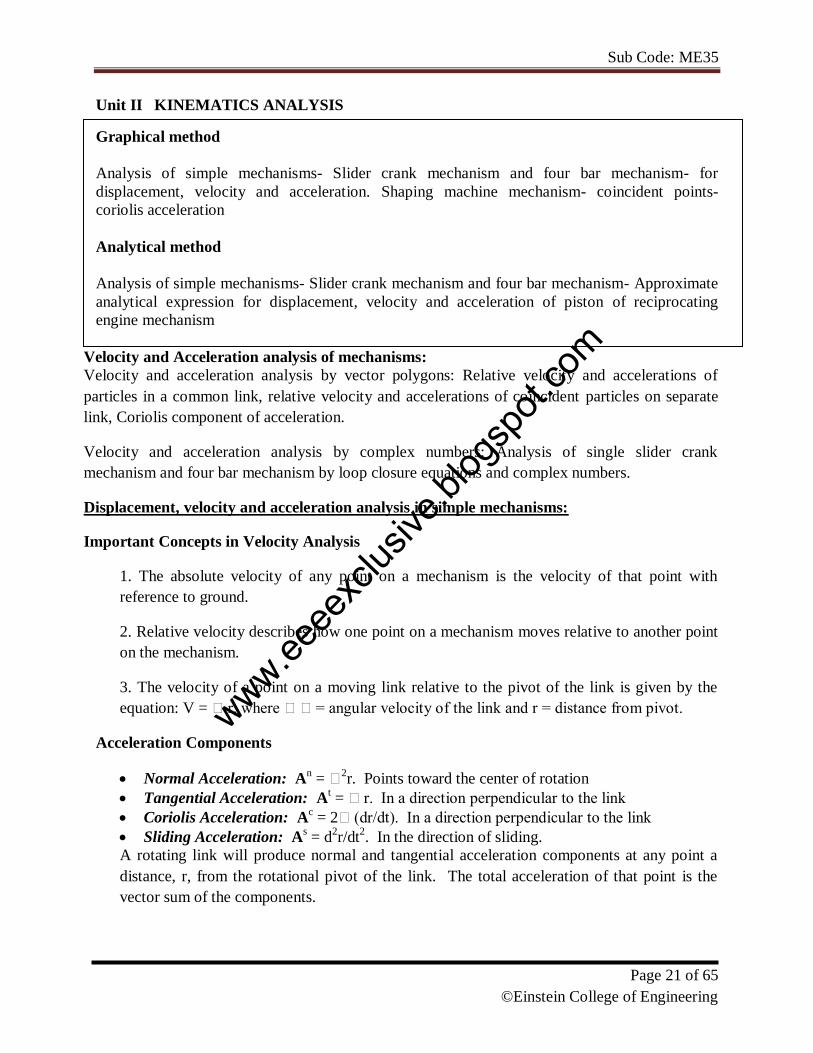
Unit II KINEMATICS ANALYSIS
Graphical method
Analysis of simple mechanisms- Slider crank mechanism and four bar mechanism- for
displacement, velocity and acceleration. Shaping machine mechanism- coincident points-
coriolis acceleration
Analytical method
Analysis of simple mechanisms- Slider crank mechanism and four bar mechanism- Approximate
analytical expression for displacement, velocity and acceleration of piston of reciprocating
engine mechanism
Velocity and Acceleration analysis of mechanisms:
Velocity and acceleration analysis by vector polygons: Relative velocity and accelerations of
particles in a common link, relative velocity and accelerations of coincident particles on separate
link, Coriolis component of acceleration.
Velocity and acceleration analysis by complex numbers: Analysis of single slider crank
mechanism and four bar mechanism by loop closure equations and complex numbers.
Displacement, velocity and acceleration analysis in simple mechanisms:
Important Concepts in Velocity Analysis
1. The absolute velocity of any point on a mechanism is the velocity of that point with
reference to ground.
2. Relative velocity describes how one point on a mechanism moves relative to another point
on the mechanism.
3. The velocity of a point on a moving link relative to the pivot of the link is given by the
equation: V = r, where = angular velocity of the link and r = distance from pivot.
Acceleration Components
Normal Acceleration: An =
2r. Points toward the center of rotation
Tangential Acceleration: At = r. In a direction perpendicular to the link
Coriolis Acceleration: Ac = 2(dr/dt). In a direction perpendicular to the link
Sliding Acceleration: As = d
2r/dt
2. In the direction of sliding.
A rotating link will produce normal and tangential acceleration components at any point a
distance, r, from the rotational pivot of the link. The total acceleration of that point is the
vector sum of the components.
www.eeee
xclus
ive.bl
ogsp
ot.co
m

Sub Code: ME35
Page 22 of 65
©Einstein College of Engineering
A slider attached to ground experiences only sliding acceleration.
A slider attached to a rotating link (such that the slider is moving in or out along the link as the
link rotates) experiences all 4 components of acceleration. Perhaps the most confusing of these
is the coriolis acceleration, though the concept of coriolis acceleration is fairly simple. Imagine
yourself standing at the center of a merry-go-round as it spins at a constant speed (). You
begin to walk toward the outer edge of the merry-go-round at a constant speed (dr/dt). Even
though you are walking at a constant speed and the merry-go-round is spinning at a constant
speed, your total velocity is increasing because you are moving away from the center of rotation
(i.e. the edge of the merry-go-round is moving faster than the center). This is the coriolis
acceleration. In what direction did your speed increase? This is the direction of the coriolis
acceleration.
The total acceleration of a point is the vector sum of all applicable acceleration components:
A = An + A
t + A
c + A
s
These vectors and the above equation can be broken into x and y components by applying sines
and cosines to the vector diagrams to determine the x and y components of each vector. In this
way, the x and y components of the total acceleration can be found.
Graphical Method, Velocity and Acceleration polygons :
Graphical velocity analysis:
It is a very short step (using basic trigonometry with sines and cosines) to convert the graphical
results into numerical results. The basic steps are these:
1. Set up a velocity reference plane with a point of zero velocity designated.
2. Use the equation, V = r, to calculate any known linkage velocities.
3. Plot your known linkage velocities on the velocity plot. A linkage that is rotating about
ground gives an absolute velocity. This is a vector that originates at the zero velocity point
and runs perpendicular to the link to show the direction of motion. The vector, VA, gives the
velocity of point A.
www.eeee
xclus
ive.bl
ogsp
ot.co
m

Sub Code: ME35
Page 23 of 65
©Einstein College of Engineering
4. Plot all other velocity vector directions. A point on a grounded link (such as point B) will
produce an absolute velocity vector passing through the zero velocity point and perpendicular
to the link. A point on a floating link (such as B relative to point A) will produce a relative
velocity vector. This vector will be perpendicular to the link AB and pass through the
reference point (A) on the velocity diagram.
5. One should be able to form a closed triangle (for a 4-bar) that shows the vector equation:
VB = VA + VB/A where VB = absolute velocity of point B, VA = absolute velocity of point A,
and VB/A is the velocity of point B relative to point A.
Velocity Analysis of Four Bar Mechanisms:
Problems solving in Four Bar Mechanisms and additional links.
Velocity Analysis of Slider Crank Mechanisms:
Problems solving in Slider Crank Mechanisms and additional links.
Acceleration Analysis of Four Bar Mechanisms:
Problems solving in Four Bar Mechanisms and additional links.
Acceleration Analysis of Slider Crank Mechanisms:
Problems solving in Slider Crank Mechanisms and additional links.
Kinematic analysis by Complex Algebra methods:
Analysis of single slider crank mechanism and four bar mechanism by loop closure
equations and complex numbers.
vector Approach:
Relative velocity and accelerations of particles in a common link, relative velocity and
accelerations of coincident particles on separate link
Computer applications in the kinematic analysis of simple mechanisms:
Computer programming for simple mechanisms
Coincident points, Coriolis Acceleration:
Coriolis Acceleration: Ac = 2(dr/dt). In a direction perpendicular to the link. A slider
attached to ground experiences only sliding acceleration.
A slider attached to a rotating link (such that the slider is moving in or out along the link as the
link rotates) experiences all 4 components of acceleration. Perhaps the most confusing of these
is the coriolis acceleration, though the concept of coriolis acceleration is fairly simple. Imagine
yourself standing at the center of a merry-go-round as it spins at a constant speed (). You
begin to walk toward the outer edge of the merry-go-round at a constant speed (dr/dt). Even
though you are walking at a constant speed and the merry-go-round is spinning at a constant
speed, your total velocity is increasing because you are moving away from the center of rotation
(i.e. the edge of the merry-go-round is moving faster than the center). This is the coriolis
acceleration. In what direction did your speed increase? This is the direction of the coriolis
acceleration.
www.eeee
xclus
ive.bl
ogsp
ot.co
m
Sub Code: ME35
Page 24 of 65
©Einstein College of Engineering
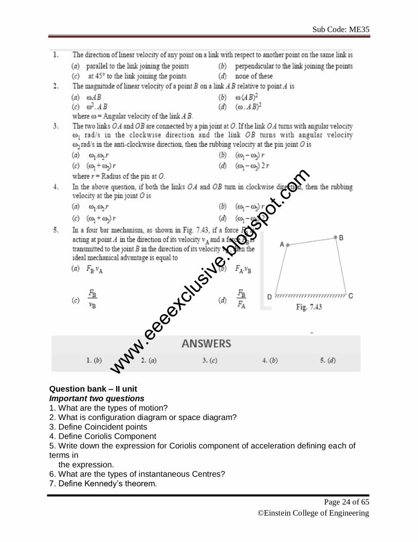
Question bank – II unit Important two questions 1. What are the types of motion? 2. What is configuration diagram or space diagram? 3. Define Coincident points 4. Define Coriolis Component 5. Write down the expression for Coriolis component of acceleration defining each of terms in the expression. 6. What are the types of instantaneous Centres? 7. Define Kennedy’s theorem.
www.eeee
xclus
ive.bl
ogsp
ot.co
m
Sub Code: ME35
Page 25 of 65
©Einstein College of Engineering
8. Define rubbing velocity at a pin joint. 9. What are the various methods used for finding out velocity of mechanism? 10. Define Instantaneous centre. 11. Define Angular Velocity ratio theorem.
Important descriptive university questions:
The Crank of a slider crank mechanisms rotates clockwise at a Constant speed of 600 r.p.m. The crank is 125 mm and connecting rod is 500 mm long. Determine 1. Linear velocity and acceleration of the mid Point of the connecting rod, and 2. Angular velocity and angular acceleration of the connecting rod, at a crank angle of 45° from inner dead centre position.
In a four link mechanism, the dimensions of the links are AB=200 mm, BC=400mm, CD=450 mm and AD=600mm. At the instant when DAB=90°, the link AB has angular velocity of 36 rad/s in the clockwise direction. Determine (i) The velocity of point C, (ii) The velocity of point E on the link BC When BE =200 mm (iii) the angular velocities of links BC and CD, iv) acceleration of link of link BC.
Derive the expressions for Velocity and acceleration of piston in reciprocating steam engine mechanism with neat sketch
Derive the expression for Coriolis component of acceleration with neat sketch
In a slider crank mechanism, the length of the crank and the connecting rod are 100 mm and 400 mm respectively./ The crank [position is 45° from IDC, the crank shaft speed is 600 r.p.m., Clockwise. Using analytical method Determine (1) Velocity and acceleration of the slider, and (2) Angular velocity and angular acceleration of the connecting rod.
Locate all instantaneous centers of the slider crank mechanism; the length of crank OB and Connecting rod AB are 125 mm and 500 mm respectively. The crank speed is 600 rpm clockwise. When the crank has turned 45° from the IDC, Determine (i)velocity of slider’ A’ (ii)Angular Velocity of connecting rod ‘AB’.
References
1. Ambekar A. G., Mechanism and Machine Theory, Prentice Hall of India, New Delhi, 2007.
2. Khurmi R.S., Gupta J.K., Theory of machines, S. Chand company limited, New Delhi, 2009.
Web site:
www. nptel.iitm.ac.in (National programme on technology enhanced learning by IIT, India)
http://www.scribd.com/doc/18424291/Kinematics-of-Machines
www.eeee
xclus
ive.bl
ogsp
ot.co
m
Sub Code: ME35
Page 26 of 65
©Einstein College of Engineering
3. KINEMATICS OF CAMS
INTRODUCTION
A cam is a mechanical device used to transmit motion to a follower by direct contact. The
driver is called the cam and the driven member is called the follower. In a cam follower pair, the
cam normally rotates while the follower may translate or oscillate. A familiar example is the
camshaft of an automobile engine, where the cams drive the push rods (the followers) to open
and close the valves in synchronization with the motion of the pistons.
Types of cams
Cams can be classified based on their physical shape.
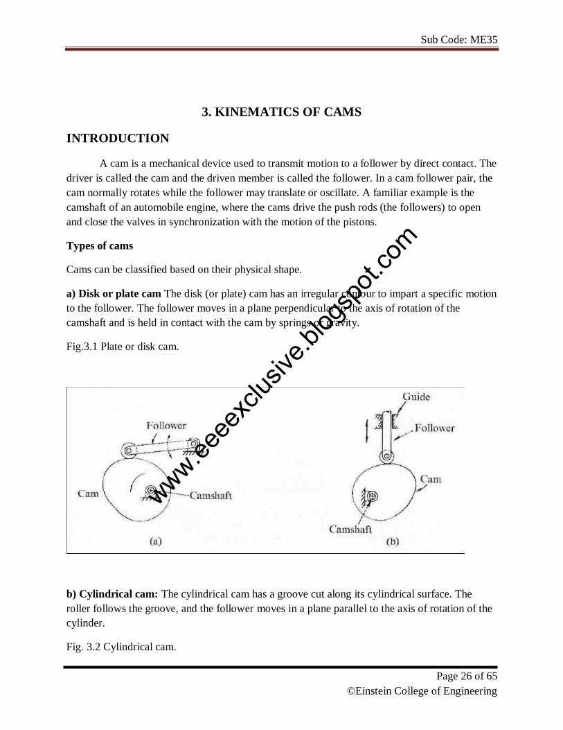
a) Disk or plate cam The disk (or plate) cam has an irregular contour to impart a specific motion
to the follower. The follower moves in a plane perpendicular to the axis of rotation of the
camshaft and is held in contact with the cam by springs or gravity.
Fig.3.1 Plate or disk cam.
b) Cylindrical cam: The cylindrical cam has a groove cut along its cylindrical surface. The
roller follows the groove, and the follower moves in a plane parallel to the axis of rotation of the
cylinder.
Fig. 3.2 Cylindrical cam.
www.eeee
xclus
ive.bl
ogsp
ot.co
m

Sub Code: ME35
Page 27 of 65
©Einstein College of Engineering
c) Translating cam. The translating cam is a contoured or grooved plate sliding on a guiding
surface(s). The follower may oscillate (Fig. 3.3a) or reciprocate (Fig. 3.3b). The contour or the
shape of the groove is determined by the specified motion of the follower.
Fig. 3.3 translating cam
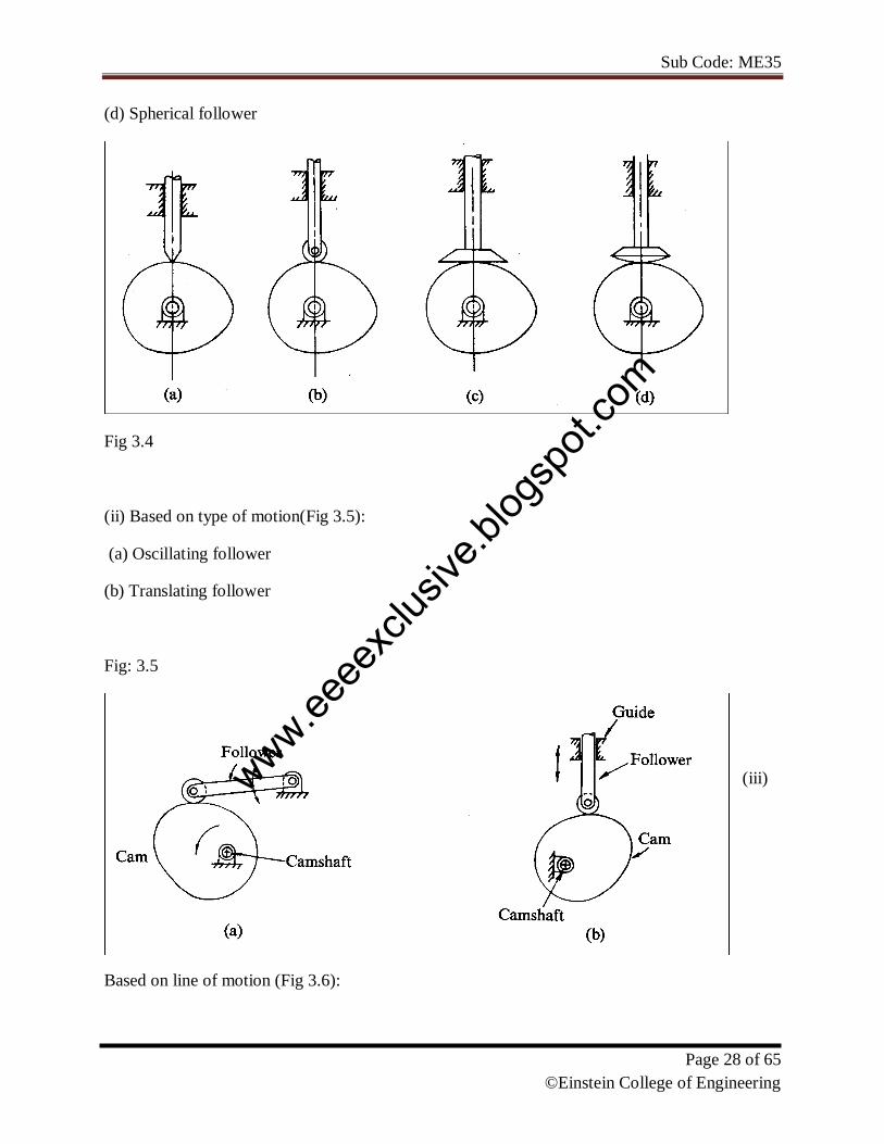
Types of followers(Fig 3.4):
(i) Based on surface in contact.
(a) Knife edge follower
(b) Roller follower
(c) Flat faced follower
www.eeee
xclus
ive.bl
ogsp
ot.co
m
Sub Code: ME35
Page 28 of 65
©Einstein College of Engineering
(d) Spherical follower
Fig 3.4
(ii) Based on type of motion(Fig 3.5):
(a) Oscillating follower
(b) Translating follower
Fig: 3.5
(iii)
Based on line of motion (Fig 3.6):
www.eeee
xclus
ive.bl
ogsp
ot.co
m

Sub Code: ME35
Page 29 of 65
©Einstein College of Engineering
(a) Radial follower: The lines of movement of in-line cam followers pass through the centers of
the camshafts
(b) Off-set follower: For this type, the lines of movement are offset from the centers of the
camshafts
Fig
3.6
Cam
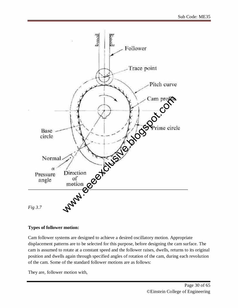
nomenclature (Fig. 3.7):
Cam Profile The contour of the working surface of the cam.
Tracer Point The point at the knife edge of a follower, or the center of a roller, or the center of a
spherical face.
Pitch Curve The path of the tracer point.
Base Circle The smallest circle drawn, tangential to the cam profile, with its center on the axis of
the camshaft. The size of the base circle determines the size of
the cam.
Prime Circle The smallest circle drawn, tangential to the pitch curve, with its center on
the axis of the camshaft.
Pressure Angle The angle between the normal to the pitch curve and the direction of
motion of the follower at the point of contact.
www.eeee
xclus
ive.bl
ogsp
ot.co
m
Sub Code: ME35
Page 30 of 65
©Einstein College of Engineering
Fig 3.7
Types of follower motion:
Cam follower systems are designed to achieve a desired oscillatory motion. Appropriate
displacement patterns are to be selected for this purpose, before designing the cam surface. The
cam is assumed to rotate at a constant speed and the follower raises, dwells, returns to its original
position and dwells again through specified angles of rotation of the cam, during each revolution
of the cam. Some of the standard follower motions are as follows:
They are, follower motion with,
www.eeee
xclus
ive.bl
ogsp
ot.co
m

Sub Code: ME35
Page 31 of 65
©Einstein College of Engineering
(a) Uniform velocity
(b) Modified uniform velocity
(c) Uniform acceleration and deceleration
(d) Simple harmonic motion
(e) Cycloidal motion
Displacement diagrams: In a cam follower system, the motion of the follower is very
important. Its displacement can be plotted against the angular displacement θ of the cam and it is
called as the displacement diagram. The displacement of the follower is plotted along the y-axis
and angular displacement θ of the cam is plotted along x-axis. From the displacement diagram,
velocity and acceleration of the follower can also be plotted for different angular displacements θ
of the cam. The displacement, velocity and acceleration diagrams are plotted for one cycle of
operation i.e., one rotation of the cam. Displacement diagrams are basic requirements for the
construction of cam profiles. Construction of displacement diagrams and calculation of velocities
and accelerations of followers with different types of motions are discussed in the following
sections.
(a) Follower motion with Uniform velocity:
Fig.3.8 shows the displacement, velocity and acceleration patterns of a follower having uniform
velocity type of motion. Since the follower moves with constant velocity, during rise and fall, the
displacement varies linearly with θ. Also, since the velocity changes from zero to a finite value,
within no time, theoretically, the acceleration becomes infinite at the beginning and end of rise
and fall.
www.eeee
xclus
ive.bl
ogsp
ot.co
m

Sub Code: ME35
Page 32 of 65
©Einstein College of Engineering
Fig
3.8
(b)
Follower motion with modified uniform velocity:
www.eeee
xclus
ive.bl
ogsp
ot.co
m
Sub Code: ME35
Page 33 of 65
©Einstein College of Engineering
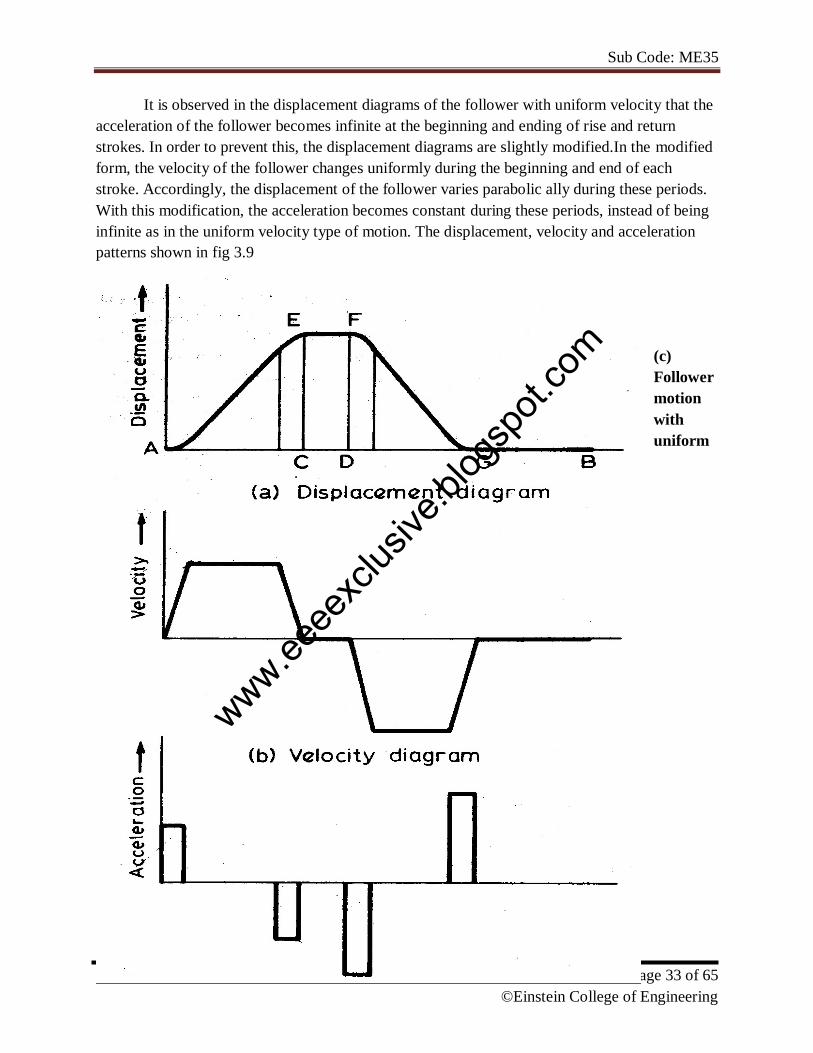
It is observed in the displacement diagrams of the follower with uniform velocity that the
acceleration of the follower becomes infinite at the beginning and ending of rise and return
strokes. In order to prevent this, the displacement diagrams are slightly modified.In the modified
form, the velocity of the follower changes uniformly during the beginning and end of each
stroke. Accordingly, the displacement of the follower varies parabolic ally during these periods.
With this modification, the acceleration becomes constant during these periods, instead of being
infinite as in the uniform velocity type of motion. The displacement, velocity and acceleration
patterns shown in fig 3.9
(c)
Follower
motion
with
uniform
www.eeee
xclus
ive.bl
ogsp
ot.co
m
Sub Code: ME35
Page 34 of 65
©Einstein College of Engineering
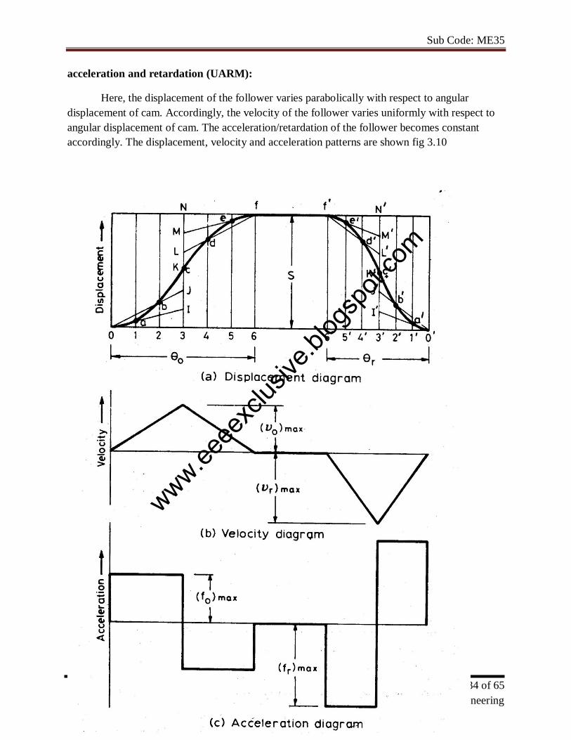
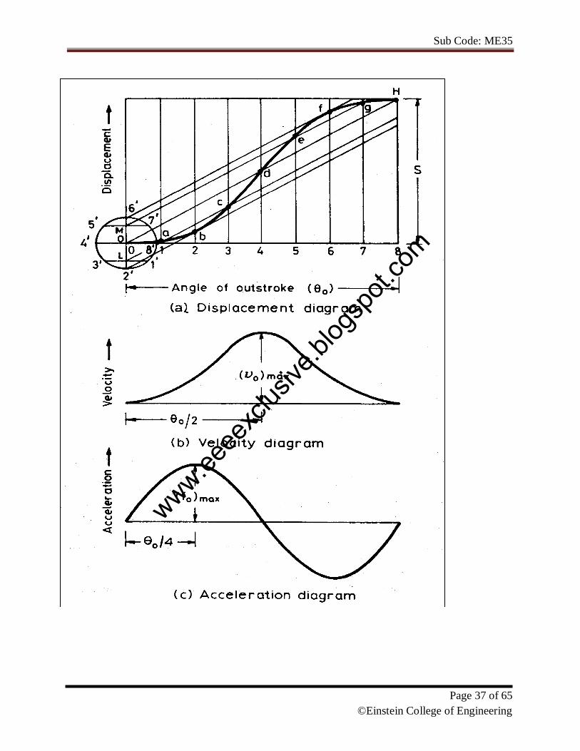
acceleration and retardation (UARM):
Here, the displacement of the follower varies parabolically with respect to angular
displacement of cam. Accordingly, the velocity of the follower varies uniformly with respect to
angular displacement of cam. The acceleration/retardation of the follower becomes constant
accordingly. The displacement, velocity and acceleration patterns are shown fig 3.10
www.eeee
xclus
ive.bl
ogsp
ot.co
m

Sub Code: ME35
Page 35 of 65
©Einstein College of Engineering
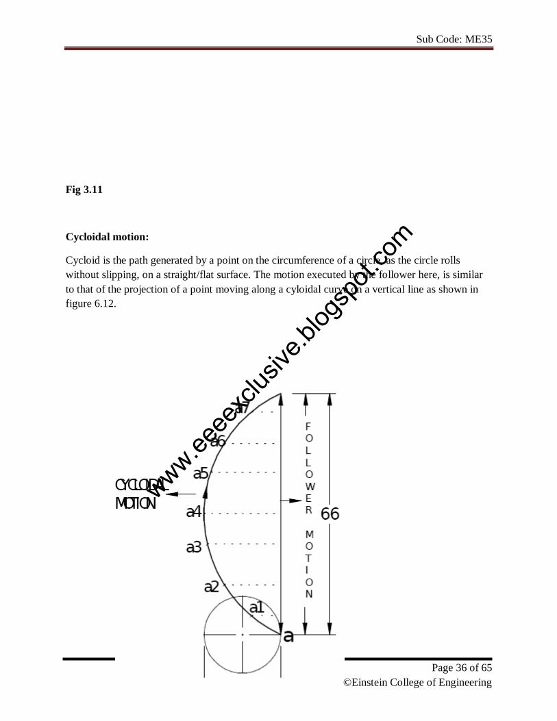
(d) Simple Harmonic Motion: In fig3.11, the motion executed by point Pl, which is the
projection of point P on the vertical diameter is called simple harmonic motion. Here, P moves
with uniform angular velocity ωp, along a circle of radius r (r = s/2).
www.eeee
xclus
ive.bl
ogsp
ot.co
m
Sub Code: ME35
Page 36 of 65
©Einstein College of Engineering
Fig 3.11
Cycloidal motion:
Cycloid is the path generated by a point on the circumference of a circle, as the circle rolls
without slipping, on a straight/flat surface. The motion executed by the follower here, is similar
to that of the projection of a point moving along a cyloidal curve on a vertical line as shown in
figure 6.12.
www.eeee
xclus
ive.bl
ogsp
ot.co
m
Sub Code: ME35
Page 37 of 65
©Einstein College of Engineering
www.eeee
xclus
ive.bl
ogsp
ot.co
m

Sub Code: ME35
Page 38 of 65
©Einstein College of Engineering
(1) Draw the cam profile for following conditions:
Follower type = Knife edged, in-line; lift = 50mm; base circle radius = 50mm; out stroke with
SHM, for 600 cam rotation; dwell for 45
0cam rotation; return stroke with SHM, for 90
ocam
rotation; dwell for the remaining period.
(2) Draw the cam profile for the same operating conditions of with the follower off set by 10 mm
to the left of cam center.
Cam profile:
www.eeee
xclus
ive.bl
ogsp
ot.co
m
Sub Code: ME35
Page 39 of 65
©Einstein College of Engineering
Cam profile with 10 mm offset:
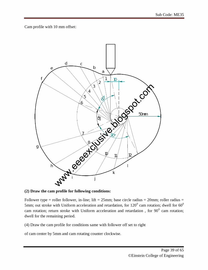
(2) Draw the cam profile for following conditions:
Follower type = roller follower, in-line; lift = 25mm; base circle radius = 20mm; roller radius =
5mm; out stroke with Uniform acceleration and retardation, for 1200 cam rotation; dwell for 60
0
cam rotation; return stroke with Uniform acceleration and retardation , for 900 cam rotation;
dwell for the remaining period.
(4) Draw the cam profile for conditions same with follower off set to right
of cam center by 5mm and cam rotating counter clockwise.
www.eeee
xclus
ive.bl
ogsp
ot.co
m

Sub Code: ME35
Page 40 of 65
©Einstein College of Engineering
Displacement Diagram :
Cam profile ;
www.eeee
xclus
ive.bl
ogsp
ot.co
m

Sub Code: ME35
Page 41 of 65
©Einstein College of Engineering
Cam profile with 5 mm offset
(3) Draw the cam profile for following conditions:
Follower type = knife edged follower, in line; lift = 30mm; base circle radius = 20mm;out stroke
with uniform velocity in 1200 of cam rotation; dwell for 60
0; return stroke with uniform velocity,
during 900 of cam rotation; dwell for the remaining period.
www.eeee
xclus
ive.bl
ogsp
ot.co
m

Sub Code: ME35
Page 42 of 65
©Einstein College of Engineering
Displacement Diagram
Cam profile
www.eeee
xclus
ive.bl
ogsp
ot.co
m
Sub Code: ME35
Page 43 of 65
©Einstein College of Engineering
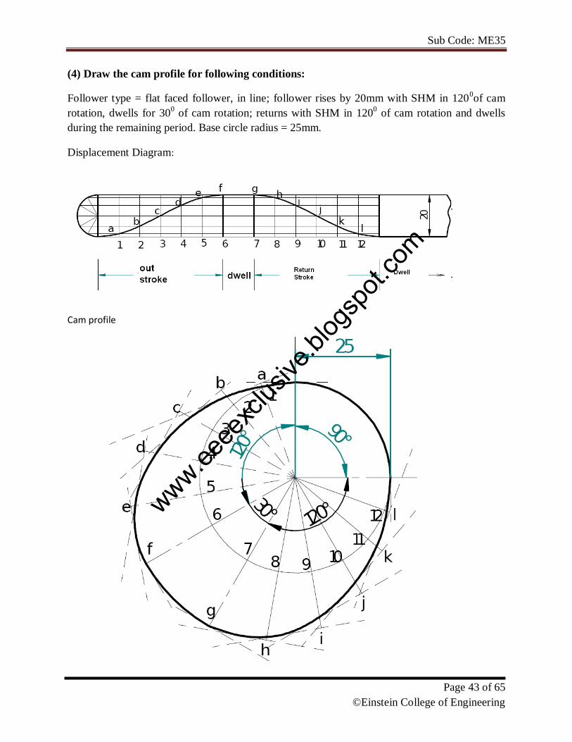
(4) Draw the cam profile for following conditions:
Follower type = flat faced follower, in line; follower rises by 20mm with SHM in 1200of cam
rotation, dwells for 300 of cam rotation; returns with SHM in 120
0 of cam rotation and dwells
during the remaining period. Base circle radius = 25mm.
Displacement Diagram:
Cam profile
www.eeee
xclus
ive.bl
ogsp
ot.co
m
Sub Code: ME35
Page 44 of 65
©Einstein College of Engineering
4. Gears
Introduction: The slip and creep in the belt or rope drives is a common phenomenon, in the
transmission of motion or power between two shafts. The effect of slip is to reduce the velocity
ratio of the drive. In precision machine, in which a definite velocity ratio is importance (as in
watch mechanism, special purpose machines..etc), the only positive drive is by means of gears or
toothed wheels.
Gears are machine elements that transmit motion by means of successively engaging teeth. The
gear teeth act like small levers. Gears are highly efficient (nearly 95%) due to primarily rolling
contact between the teeth, thus the motion transmitted is considered as positive.
Gears essentially allow positive engagement between teeth so high forces can be transmitted
while still undergoing essentially rolling contact. Gears do not depend on friction and do best
when friction is minimized.
4.1 Gear Classification: Gears may be classified according to the relative position of the
axes of revolution. The axes may be
1. Gears for connecting parallel shafts,
2. Gears for connecting intersecting shafts,
3. Gears for neither parallel nor intersecting shafts.
Gears for connecting parallel shafts
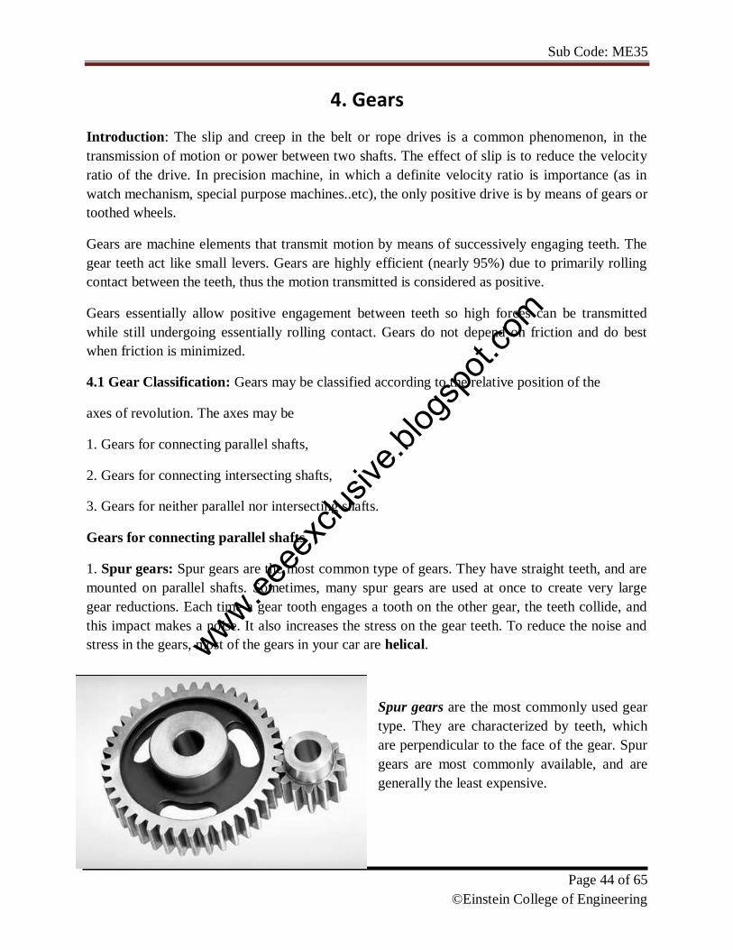
1. Spur gears: Spur gears are the most common type of gears. They have straight teeth, and are
mounted on parallel shafts. Sometimes, many spur gears are used at once to create very large
gear reductions. Each time a gear tooth engages a tooth on the other gear, the teeth collide, and
this impact makes a noise. It also increases the stress on the gear teeth. To reduce the noise and
stress in the gears, most of the gears in your car are helical.
Spur gears are the most commonly used gear
type. They are characterized by teeth, which
are perpendicular to the face of the gear. Spur
gears are most commonly available, and are
generally the least expensive.
www.eeee
xclus
ive.bl
ogsp
ot.co
m
Sub Code: ME35
Page 45 of 65
©Einstein College of Engineering
Limitations: Spur gears generally cannot be used when a direction change between the two
shafts is required.
Advantages: Spur gears are easy to find, inexpensive, and efficient.
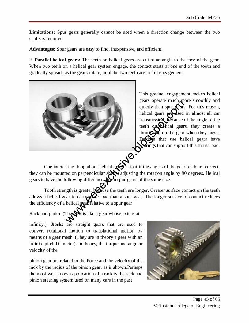
2. Parallel helical gears: The teeth on helical gears are cut at an angle to the face of the gear.
When two teeth on a helical gear system engage, the contact starts at one end of the tooth and
gradually spreads as the gears rotate, until the two teeth are in full engagement.
This gradual engagement makes helical
gears operate much more smoothly and
quietly than spur gears. For this reason,
helical gears are used in almost all car
transmission. Because of the angle of the
teeth on helical gears, they create a
thrust load on the gear when they mesh.
Devices that use helical gears have
bearings that can support this thrust load.
One interesting thing about helical gears is that if the angles of the gear teeth are correct,
they can be mounted on perpendicular shafts, adjusting the rotation angle by 90 degrees. Helical
gears to have the following differences from spur gears of the same size:
Tooth strength is greater because the teeth are longer, Greater surface contact on the teeth
allows a helical gear to carry more load than a spur gear. The longer surface of contact reduces
the efficiency of a helical gear relative to a spur gear
Rack and pinion (The rack is like a gear whose axis is at
infinity.): Racks are straight gears that are used to
convert rotational motion to translational motion by
means of a gear mesh. (They are in theory a gear with an
infinite pitch Diameter). In theory, the torque and angular
velocity of the
pinion gear are related to the Force and the velocity of the
rack by the radius of the pinion gear, as is shown.Perhaps
the most well-known application of a rack is the rack and
pinion steering system used on many cars in the past
www.eeee
xclus
ive.bl
ogsp
ot.co
m
Sub Code: ME35
Page 46 of 65
©Einstein College of Engineering
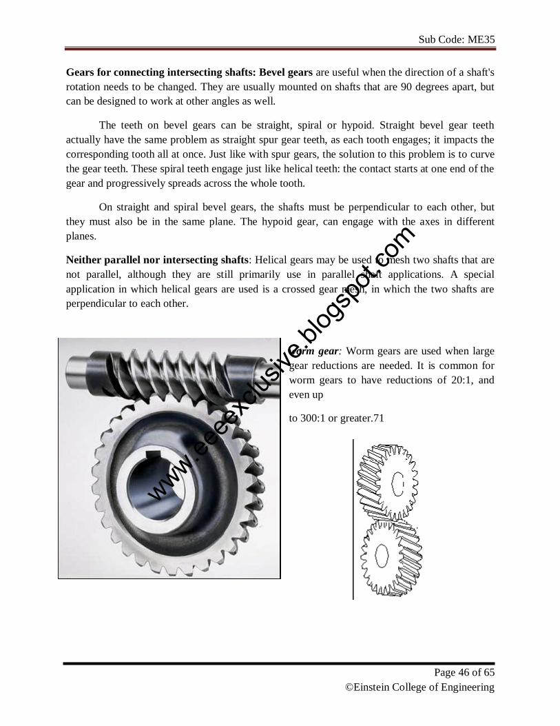
Gears for connecting intersecting shafts: Bevel gears are useful when the direction of a shaft's
rotation needs to be changed. They are usually mounted on shafts that are 90 degrees apart, but
can be designed to work at other angles as well.
The teeth on bevel gears can be straight, spiral or hypoid. Straight bevel gear teeth
actually have the same problem as straight spur gear teeth, as each tooth engages; it impacts the
corresponding tooth all at once. Just like with spur gears, the solution to this problem is to curve
the gear teeth. These spiral teeth engage just like helical teeth: the contact starts at one end of the
gear and progressively spreads across the whole tooth.
On straight and spiral bevel gears, the shafts must be perpendicular to each other, but
they must also be in the same plane. The hypoid gear, can engage with the axes in different
planes.
Neither parallel nor intersecting shafts: Helical gears may be used to mesh two shafts that are
not parallel, although they are still primarily use in parallel shaft applications. A special
application in which helical gears are used is a crossed gear mesh, in which the two shafts are
perpendicular to each other.
worm gear: Worm gears are used when large
gear reductions are needed. It is common for
worm gears to have reductions of 20:1, and
even up
to 300:1 or greater.71
www.eeee
xclus
ive.bl
ogsp
ot.co
m

Sub Code: ME35
Page 47 of 65
©Einstein College of Engineering
TERMINOLOGY:
Addendum: The radial distance between the Pitch Circle and the top of the teeth.
Arc of Action: Is the arc of the Pitch Circle between the beginning and the end of the
engagement of a given pair of teeth.
Arc of Approach: Is the arc of the Pitch Circle between the first point of contact of the gear
teeth and the Pitch Point.
Arc of Recession: That arc of the Pitch Circle between the Pitch Point and the last point of
contact of the gear teeth.
Backlash: Play between mating teeth.
Base Circle: The circle from which is generated the involute curve upon which the tooth profile
is based.
Center Distance: The distance between centers of two gears.
Chordal Addendum: The distance between a chord, passing through the points where the Pitch
Circle crosses the tooth profile, and the tooth top.
Chordal Thickness: The thickness of the tooth measured along a chord passing through the
points where the Pitch Circle crosses the tooth profile.
Circular Pitch: Millimeter of Pitch Circle circumference per tooth.
www.eeee
xclus
ive.bl
ogsp
ot.co
m

Sub Code: ME35
Page 48 of 65
©Einstein College of Engineering
Circular Thickness: The thickness of the tooth measured along an arc following the Pitch Circle
Clearance: The distance between the top of a tooth and the bottom of the space into which it fits
on the meshing gear.
Contact Ratio: The ratio of the length of the Arc of Action to the Circular Pitch.
Dedendum: The radial distance between the bottom of the tooth to pitch circle.
Diametral Pitch: Teeth per mm of diameter.
Face: The working surface of a gear tooth, located between the pitch diameter and the top of the
tooth.
Face Width: The width of the tooth measured parallel to the gear axis.
Flank: The working surface of a gear tooth, located between the pitch diameter and the bottom
of the teeth
Gear: The larger of two meshed gears. If both gears are the same size, they are both called
"gears".
Land: The top surface of the tooth.
Line of Action: That line along which the point of contact between gear teeth travels,between
the first point of contact and the last.
Module: Millimeter of Pitch Diameter to Teeth.
Pinion: The smaller of two meshed gears.
Pitch Circle: The circle, the radius of which is equal to the distance from the center of the gear
to the pitch point.
Diametral pitch: Teeth per millimeter of pitch diameter.
Pitch Point: The point of tangency of the pitch circles of two meshing gears, where the Line of
Centers crosses the pitch circles.
Pressure Angle: Angle between the Line of Action and a line perpendicular to the Line of
Centers.
Profile Shift: An increase in the Outer Diameter and Root Diameter of a gear, introduced
to lower the practical tooth number or acheive a non-standard Center Distance.
Ratio: Ratio of the numbers of teeth on mating gears.
www.eeee
xclus
ive.bl
ogsp
ot.co
m

Sub Code: ME35
Page 49 of 65
©Einstein College of Engineering
Root Circle: The circle that passes through the bottom of the tooth spaces.
Root Diameter: The diameter of the Root Circle.
Working Depth: The depth to which a tooth extends into the space between teeth on the mating
gear.
Fundamental Law of Gear-Tooth
Pitch point divides the line between the line of
centers and its position decides the velocity ratio of
the two teeth. The above expression is the
fundamental law of gear-tooth action.
Formation of teeth:
Involute teeth
Cycloidal teeth
Involute curve:
The curve most commonly used for gear-tooth
profiles is the involute of a circle. This involute
curve is the path traced by a point on a line as the line
rolls without slipping on the circumference of a circle. It may also be defined as a path traced by
the end of a string, which is originally wrapped on a circle when the string is unwrapped from
the circle. The circle from which the involute is derived is called
the base circle.
www.eeee
xclus
ive.bl
ogsp
ot.co
m
Sub Code: ME35
Page 50 of 65
©Einstein College of Engineering
Cycloidal Curve
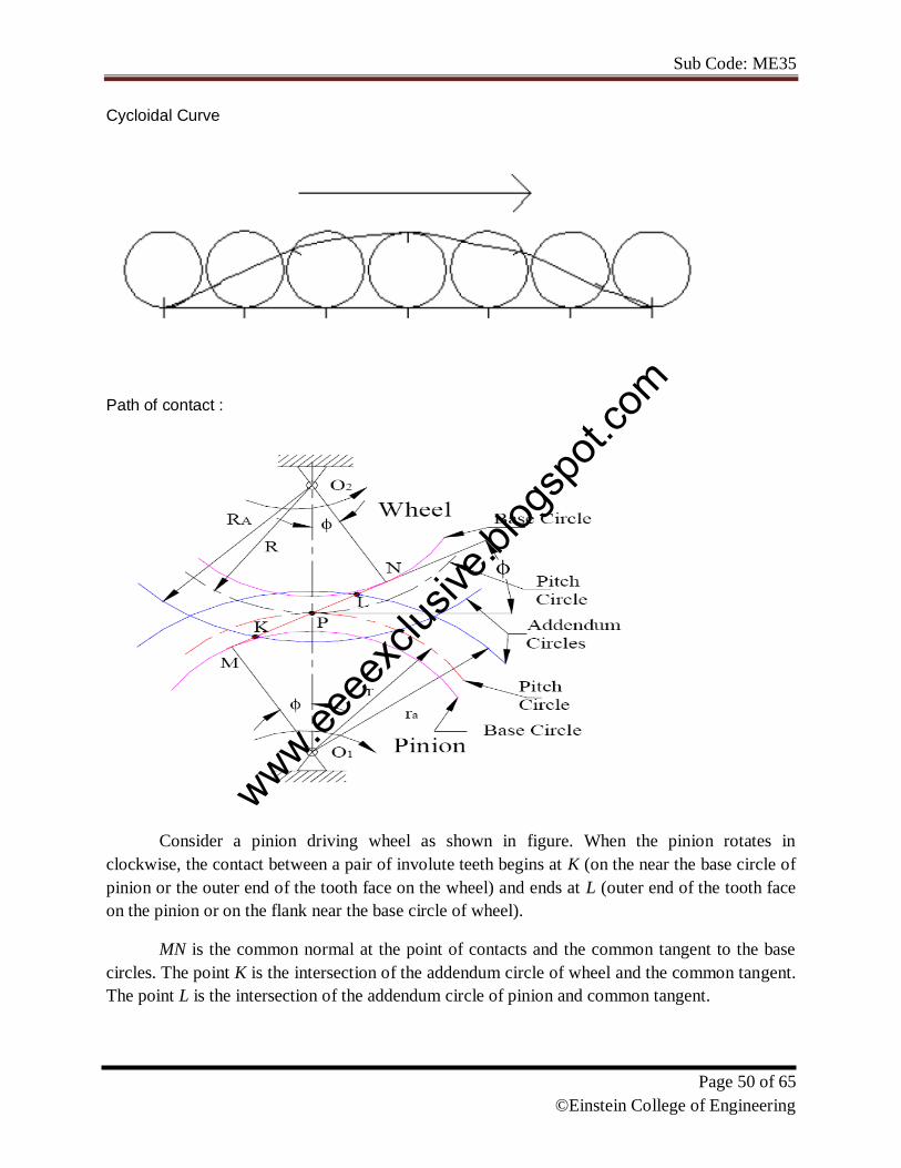
Path of contact :
Consider a pinion driving wheel as shown in figure. When the pinion rotates in
clockwise, the contact between a pair of involute teeth begins at K (on the near the base circle of
pinion or the outer end of the tooth face on the wheel) and ends at L (outer end of the tooth face
on the pinion or on the flank near the base circle of wheel).
MN is the common normal at the point of contacts and the common tangent to the base
circles. The point K is the intersection of the addendum circle of wheel and the common tangent.
The point L is the intersection of the addendum circle of pinion and common tangent.
www.eeee
xclus
ive.bl
ogsp
ot.co
m
Sub Code: ME35
Page 51 of 65
©Einstein College of Engineering
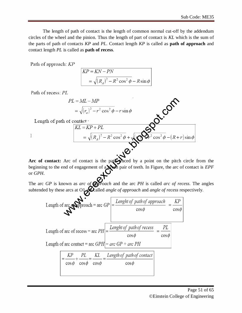
The length of path of contact is the length of common normal cut-off by the addendum
circles of the wheel and the pinion. Thus the length of part of contact is KL which is the sum of
the parts of path of contacts KP and PL. Contact length KP is called as path of approach and
contact length PL is called as path of recess.
Arc of contact: Arc of contact is the path traced by a point on the pitch circle from the
beginning to the end of engagement of a given pair of teeth. In Figure, the arc of contact is EPF
or GPH.
The arc GP is known as arc of approach and the arc PH is called arc of recess. The angles
subtended by these arcs at O1 are called angle of approach and angle of recess respectively.
www.eeee
xclus
ive.bl
ogsp
ot.co
m
Sub Code: ME35
Page 52 of 65
©Einstein College of Engineering
Contact Ratio (or Number of Pairs of Teeth in Contact)
The contact ratio or the number of pairs of teeth in contact is defined as the ratio of the
length of the arc of contact to the circular pitch.
Continuous motion transfer requires two pairs of teeth in contact at the ends of the
path of contact, though there is only one pair in contact in the middle of the path, as in Figure.
The average number of teeth in contact is an important parameter - if it is too low due to the use
of inappropriate profile shifts or to an excessive centre distance. The manufacturing inaccuracies
may lead to loss of kinematic continuity - that is to impact, vibration and noise The average
number of teeth in contact is also a guide to load sharing between teeth; it is termed the contact
ratio
www.eeee
xclus
ive.bl
ogsp
ot.co
m

Sub Code: ME35
Page 53 of 65
©Einstein College of Engineering
The tooth tip of the pinion will then undercut the tooth on the wheel at the
root and damages part of the involute profile. This effect is known as
interference, and occurs when the teeth are being cut and weakens the tooth at its root.
In general, the phenomenon, when the tip of tooth undercuts the root on its mating gear is
known as interference. Similarly, if the radius of the addendum circles of the wheel increases
beyond O2M, then the tip of tooth on wheel will cause interference with the tooth on pinion. The
points M and N are called interference points.
Interference may be avoided if the path of the contact does not extend beyond
interference points. The limiting value of the radius of the addendum circle of the pinion is O1N
and of the wheel is O2M.
The interference may only be prevented, if the point of contact between the two teeth is
always on the involute profiles and if the addendum circles of the two mating gears cut the
common tangent to the base circles at the points of tangency.
Methods to avoid Interference
1. Height of the teeth may be reduced.
2. under cut of the radial flank of the pinion.
3. Centre distance may be increased. It leads to increase in pressure angle.
4. By tooth correction, the pressure angle, centre distance and base circles remain unchanged, but
tooth thickness of gear will be greater than the pinion tooth thickness.
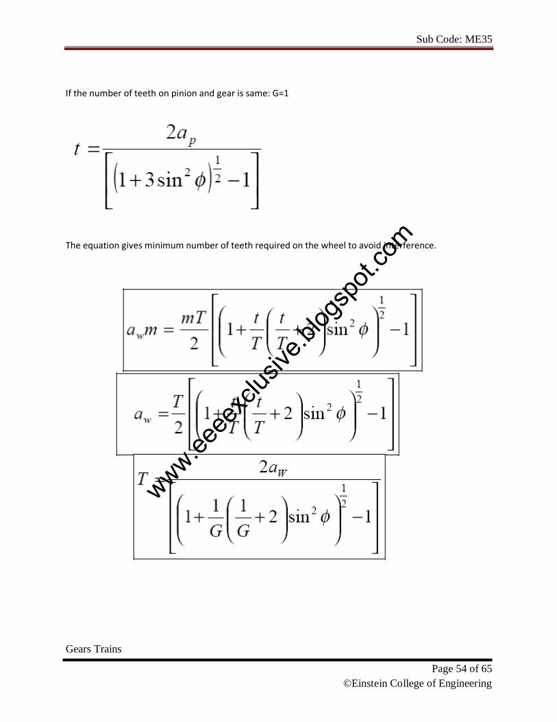
Minimum numbers of teeth on the pinion avoid Interference
The pinion turns clockwise and drives the gear as shown in Figure.
Points M and N are called interference points. i.e., if the contact takes place beyond M and N,
interference will occur.
The limiting value of addendum circle radius of pinion is O1N and the limiting value of
addendum circle radius of gear is O2M. Considering the critical addendum circle radius of gear,
the limiting number of teeth on gear can be calculated.
The equation gives minimum number of teeth required on the pinion to avoid
interference.
www.eeee
xclus
ive.bl
ogsp
ot.co
m
Sub Code: ME35
Page 54 of 65
©Einstein College of Engineering
If the number of teeth on pinion and gear is same: G=1
The equation gives minimum number of teeth required on the wheel to avoid interference.
Gears Trains
www.eeee
xclus
ive.bl
ogsp
ot.co
m
Sub Code: ME35
Page 55 of 65
©Einstein College of Engineering
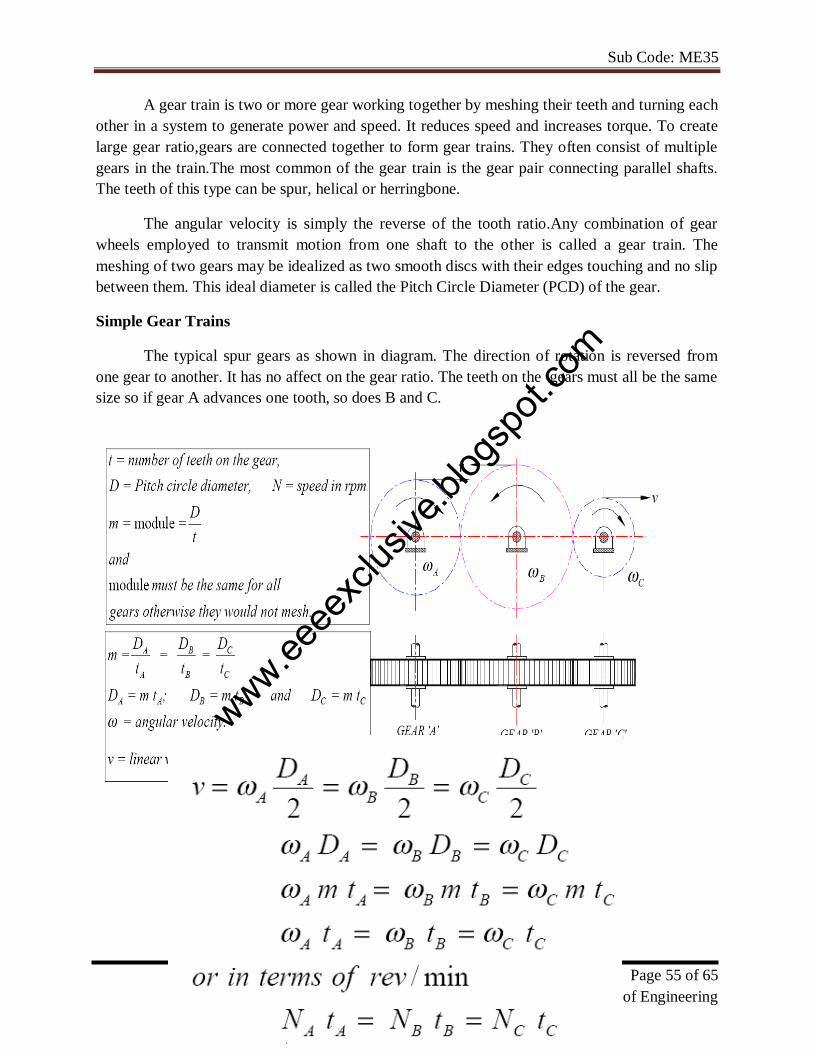
A gear train is two or more gear working together by meshing their teeth and turning each
other in a system to generate power and speed. It reduces speed and increases torque. To create
large gear ratio,gears are connected together to form gear trains. They often consist of multiple
gears in the train.The most common of the gear train is the gear pair connecting parallel shafts.
The teeth of this type can be spur, helical or herringbone.
The angular velocity is simply the reverse of the tooth ratio.Any combination of gear
wheels employed to transmit motion from one shaft to the other is called a gear train. The
meshing of two gears may be idealized as two smooth discs with their edges touching and no slip
between them. This ideal diameter is called the Pitch Circle Diameter (PCD) of the gear.
Simple Gear Trains
The typical spur gears as shown in diagram. The direction of rotation is reversed from
one gear to another. It has no affect on the gear ratio. The teeth on the gears must all be the same
size so if gear A advances one tooth, so does B and C.
www.eeee
xclus
ive.bl
ogsp
ot.co
m

Sub Code: ME35
Page 56 of 65
©Einstein College of Engineering
Compound Gear train
Compound gears are simply a chain of simple gear trains with the input of the second being the
output of the first. A chain of two pairs is shown below. Gear B is the output of the first pair and
gear C is the input of the second pair. Gears B and C are locked to the same shaft and revolve at
the same speed. For large velocities ratios, compound gear train arrangement is preferred.
www.eeee
xclus
ive.bl
ogsp
ot.co
m
Sub Code: ME35
Page 57 of 65
©Einstein College of Engineering
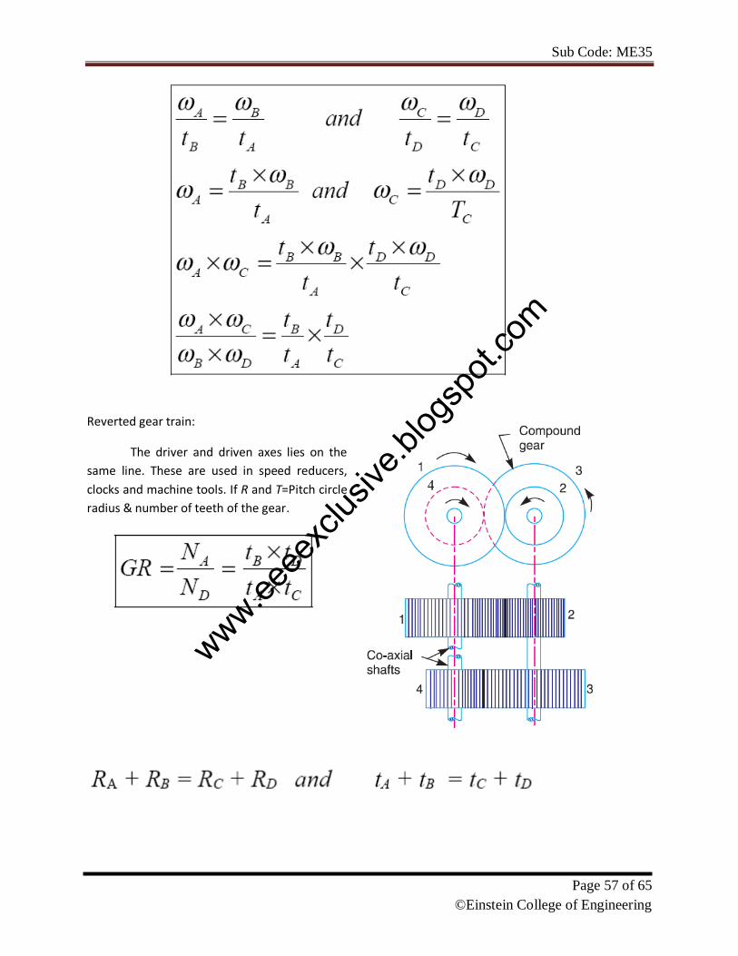
Reverted gear train:
The driver and driven axes lies on the
same line. These are used in speed reducers,
clocks and machine tools. If R and T=Pitch circle
radius & number of teeth of the gear.
www.eeee
xclus
ive.bl
ogsp
ot.co
m

Sub Code: ME35
Page 58 of 65
©Einstein College of Engineering
UNIT 5 FRICTION
FRICTION
Dry friction – Friction in screw jack – Pivot and collar friction - Plate clutches - Belt and
rope drives - Block brakes, band brakes.
Friction:
The opposing force which acts in the opposite direction of the movement of the upper
block is called the force of friction or friction.
Types or friction:
1. Static friction: It is experienced by a body, when at rest.
2. Dynamic friction: It is friction experienced by a body when in motion.
a. Sliding friction: It is friction experienced by a body when it slides over another
body.
b. Rolling friction: It is friction experienced between the surfaces which the balls or
rollers interposed between them.
c. Pivot friction: It is the friction experienced by a body due to motion of rotation.
Further classified
1. Friction between unlubricated surfaces
2. Friction between lubricated surfaces.
Laws of dry or solid friction:
The force of friction directly proportional to the normal load between the surfaces.
The force of friction is independent of the area of the contact surface for a given normal
load.
The force of friction depends upon material which the contact surfaces or made.
The force of friction is independent of the velocity of sliding of one body relative to other
body.
www.eeee
xclus
ive.bl
ogsp
ot.co
m
Sub Code: ME35
Page 59 of 65
©Einstein College of Engineering
Coefficient of friction (µ):
It is as the ratio the limiting friction (F) to the normal reaction (RN) between the two bodies.
µ= F/ RN
Angle of friction:
It may be defined as the angle which the resultant reaction R makes with normal
reactions
tan ϕ= F/ RN
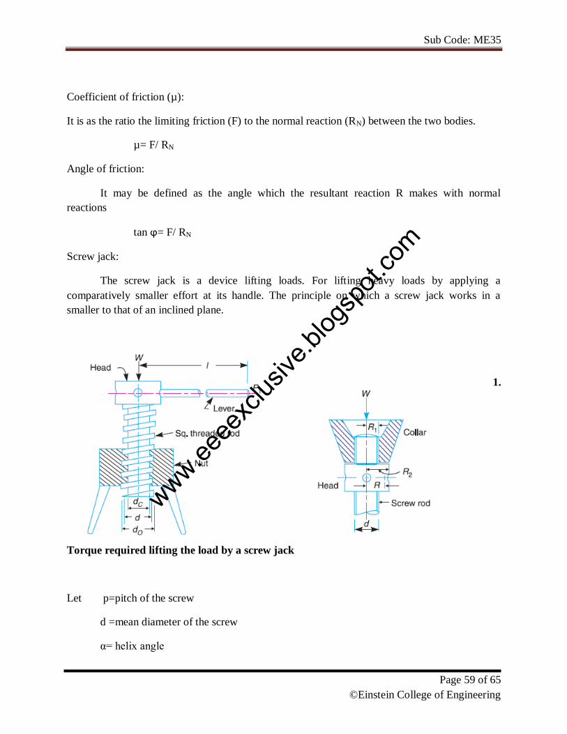
Screw jack:
The screw jack is a device lifting loads. For lifting heavy loads by applying a
comparatively smaller effort at its handle. The principle on which a screw jack works in a
smaller to that of an inclined plane.
1.
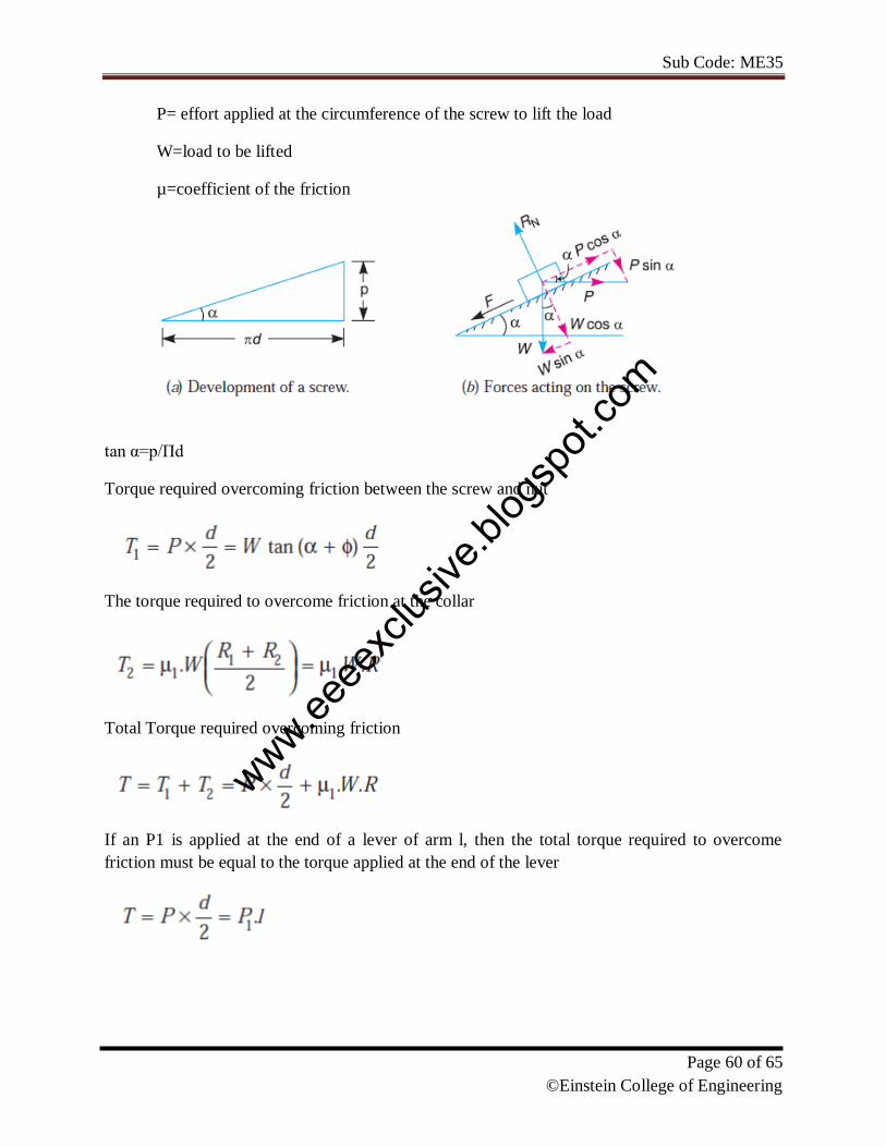
Torque required lifting the load by a screw jack
Let p=pitch of the screw
d =mean diameter of the screw
α= helix angle
www.eeee
xclus
ive.bl
ogsp
ot.co
m
Sub Code: ME35
Page 60 of 65
©Einstein College of Engineering
P= effort applied at the circumference of the screw to lift the load
W=load to be lifted
µ=coefficient of the friction
tan α=p/Πd
Torque required overcoming friction between the screw and nut
The torque required to overcome friction at the collar
Total Torque required overcoming friction
If an P1 is applied at the end of a lever of arm l, then the total torque required to overcome
friction must be equal to the torque applied at the end of the lever
www.eeee
xclus
ive.bl
ogsp
ot.co
m
Sub Code: ME35
Page 61 of 65
©Einstein College of Engineering
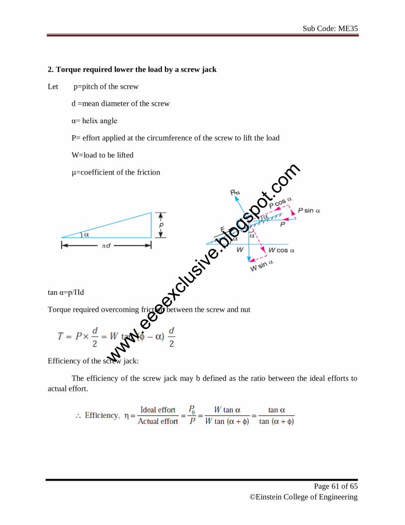
2. Torque required lower the load by a screw jack
Let p=pitch of the screw
d =mean diameter of the screw
α= helix angle
P= effort applied at the circumference of the screw to lift the load
W=load to be lifted
µ=coefficient of the friction
tan α=p/Πd
Torque required overcoming friction between the screw and nut
Efficiency of the screw jack:
The efficiency of the screw jack may b defined as the ratio between the ideal efforts to
actual effort.
www.eeee
xclus
ive.bl
ogsp
ot.co
m

Sub Code: ME35
Page 62 of 65
©Einstein College of Engineering
Self locking and over hauling of screws
Torque required to lower the load
In the above expressions ,if ϕ< α ,then the torque required to lower the load will be
negative ,the load will start moving downward without application of force, such a condition is
known as overhauling of screw.
If ϕ> α ,then the torque required to lower the load will be positive ,indicating that an
efforts applied lower the load , such a condition is known as self locking of screw
www.eeee
xclus
ive.bl
ogsp
ot.co
m
Sub Code: ME35
Page 63 of 65
©Einstein College of Engineering
BELT
The belt or ropes are used to transmit power from one shaft to another shaft by
means of pulleys which rotate at the same speed or at different speed.
Types of belt drives.
1. Light drives: belt speed up to 10m/s
2. Medium drives: speed 10m/s to 22 m/s
3. Heavy drives : Speed over 22m/s
Types of belt
1. Flat belt
2. V- belt
3. Circular belt or rope
Type of flat belt drives
Open belt drive
Cross belt drive
Quarter turn belt drive
Belt drive with idler pulley
Velocity of belt drive
It is the ratio between the velocies of the driver and follower or driven.
d1 = diameter of the driver
d2 = diameter of the follower
N1 = Speed of the driver r.p.m
N2 = Speed of the driven r.p.m
www.eeee
xclus
ive.bl
ogsp
ot.co
m
Sub Code: ME35
Page 64 of 65
©Einstein College of Engineering
Let r1 and r1 = Radii of the larger or smaller pulleys
x = Distance between the centres of the two pulleys
L = Total length of the belt.
Length of an open belt drive
Length of the cross belt drive.
Power transmitted by a belt
T1 and T2 = Tensions in the tight and slack side of the belt respectively N
r1 and r1 = Radii of the larger or smaller pulleys
v = Velocity of the belt m/s
Power = (T1-T2)v W
Ratio of driving tensions for flat belt drive
µ
θ = angle of contact
determination of angle of contact
www.eeee
xclus
ive.bl
ogsp
ot.co
m
Sub Code: ME35
Page 65 of 65
©Einstein College of Engineering
www.eeee
xclus
ive.bl
ogsp
ot.co
m