Study on supporting structures of magnets and blankets for a heliotron-type fusion reactors Study on...
23
Study on supporting Study on supporting structures of magnets and structures of magnets and blankets for a heliotron- blankets for a heliotron- type fusion reactors type fusion reactors Shinsaku Imagawa, Akio Sagara National Institute for Fusion Science 1. Introduction 2. Layout of magnets 3. Structural analysis of the magnets 4. Summary JA-US Workshop on Fusion Power Plants and Related Advanced Technologies with participation of EU, Jan. 11-13, 2005, Tokyo, Japan.
-
date post
18-Dec-2015 -
Category
Documents
-
view
215 -
download
1
Transcript of Study on supporting structures of magnets and blankets for a heliotron-type fusion reactors Study on...

Study on supporting structures of Study on supporting structures of magnets and blankets for a magnets and blankets for a
heliotron-type fusion reactorsheliotron-type fusion reactors
Shinsaku Imagawa, Akio Sagara
National Institute for Fusion Science
1. Introduction
2. Layout of magnets
3. Structural analysis of the magnets
4. Summary
JA-US Workshop on Fusion Power Plants and Related Advanced Technologies with participation of EU, Jan. 11-13, 2005, Tokyo, Japan.
1. Introduction1. IntroductionAdvantages of Helical Fusion Reactor: (1) no current-disruptions, (2) no current-drive (3) constant coil-currents (owing to inherently current-less plasma)
Disadvantages: (1) necessarily large major radius
to realize the self-ignition conditionto produce sufficient space for blankets.
(2) difficulty of replacement of HCs (3) difficulty of maintenance of blankets
–> SC magnets,especially the helical coils (HCs), must be simplifiedfor high reliability of them, good maintainability of blankets, and reasonable construction cost.
ObjectivesObjectives
(1) To survey the major parameters of the reactor with the blanket space > 1.1 m
(2) To optimize the position of poloidal coils
(3) To discuss the simplified supporting structure for SC magnets
(4) To estimate the mechanical feasibility by Finite Element Method.
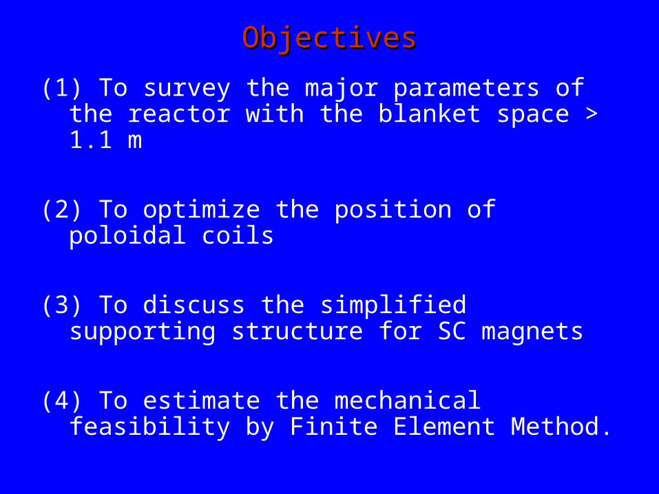
Coordinate of Helical CoilCoordinate of Helical Coil
Pitch parameter : m
ac
R0
, Coil current : I 2R0B0
0m
Coil current density : j I
W H
B0
R0
(when the shape is similar)
B0: Central toroidal fieldl: pole numberm: periodic number
Minimum gap for blanket Db=Min(ac-ap) - H/2 - 0.1 [m]
(0.1 m is a space for thermal shield.)
R0
Rc
apDb
ac
Helical Coil
Blanket
H
W
tan-1
Plasma
Poloidal Coil
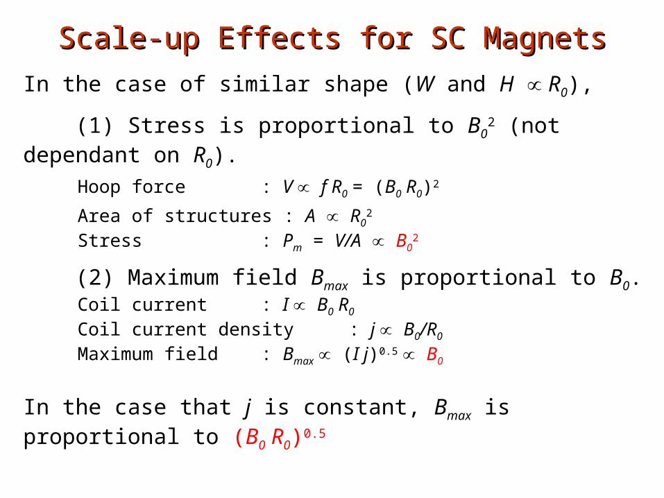
Scale-up Effects for SC MagnetsScale-up Effects for SC Magnets
In the case of similar shape (W and H ∝ R0),
(1) Stress is proportional to B02 (not dependant on R0).
Hoop force : V ∝ f R0 = (B0 R0)2
Area of structures : A ∝ R02
Stress : Pm = V/A ∝ B02
(2) Maximum field Bmax is proportional to B0.Coil current : I ∝ B0 R0
Coil current density : j ∝ B0/R0
Maximum field : Bmax ∝ (I j)0.5 ∝ B0
In the case that j is constant, Bmax is proportional to (B0 R0)0.5
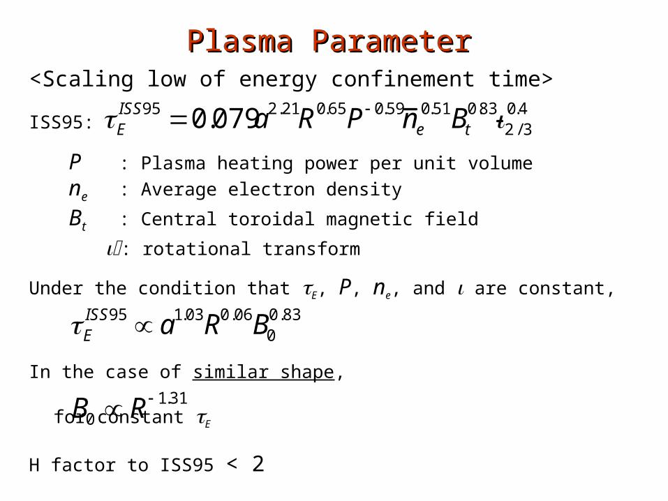
Plasma ParameterPlasma Parameter<Scaling low of energy confinement time>
ISS95:
P : Plasma heating power per unit volume
ne : Average electron density
Bt : Central toroidal magnetic field
: rotational transform
Under the condition that E, P, ne, and are constant,
In the case of similar shape,
for constant E
H factor to ISS95 < 2
EISS95 0.079a2.21R0.65P 0.59n e
0.51Bt0.832 / 3
0.4
EISS95 a1.03R0.06B0
0.83
B0 R 1.31
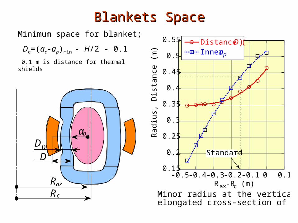
Blankets SpaceBlankets SpaceMinimum space for blanket;
Db=(ac-ap)min - H/2 - 0.1
0.1 m is distance for thermal shields
0.15
0.2
0.25
0.3
0.35
0.4
0.45
0.5
0.55
-0.5 -0.4 -0.3 -0.2 -0.1 0 0.1
Distance (D)Inner ap
Rad
ius,
Dis
tanc
e (m
)
Rax-Rc (m)
Minor radius at the verticallyelongated cross-section of LHD.
Standard
Rax
Rc
ap
DDb

Normalized Force of the Helical CoilNormalized Force of the Helical Coil
(1) The normalized forces
become lower with the
smaller .
(2) The ‘force free’ is attained
at = 0.6 - 0.85.
(3) The curves are shifted in
the positive y-axis with the
higher current density or
the lower aspect ratio. It
depends on mainly the
ratio of area occupied by
the coils in the torus
surface.
-0.1
0
0.1
0.2
0.3
0.4
0.7 0.8 0.9 1 1.1 1.2 1.3 1.4 1.5
R0/ac=10, j=50 MA/m2
R0/ac=5, j=25 MA/m2
R0/ac=3.33, j=25 MA/m2
R0/ac=3.33, j=50 MA/m2
B0
I
Coil pitch parameter, (=m/l*ac/R0)
l = 2
l = 3
LHD
FFHR2
FFHR1
W
H
ac
B0/R0 = 1, W/H = 2
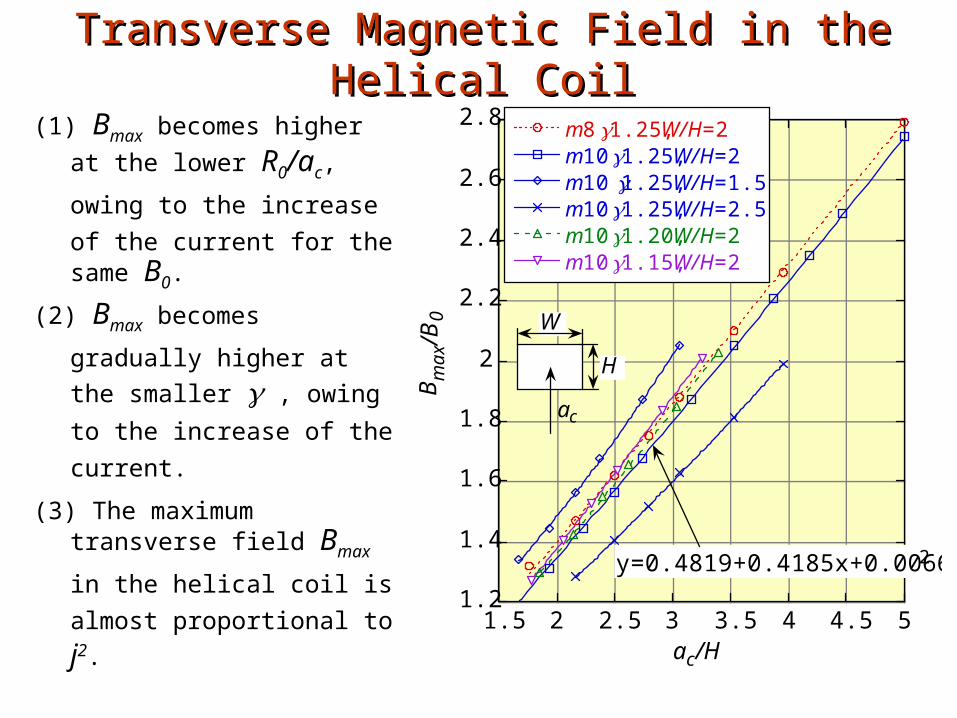
Transverse Magnetic Field in the Helical CoilTransverse Magnetic Field in the Helical Coil
(1) Bmax becomes higher at the
lower R0/ac, owing to the
increase of the current for the same B0.
(2) Bmax becomes gradually
higher at the smaller ,
owing to the increase of
the current.
(3) The maximum transverse field Bmax in the helical coil
is almost proportional to j2.
1.2
1.4
1.6
1.8
2
2.2
2.4
2.6
2.8
1.5 2 2.5 3 3.5 4 4.5 5
m8 1.25, W/H=2m10 1.25, W/H=2m101.25, W/H=1.5m10 1.25, W/H=2.5m10 1.20, W/H=2m10 1.15, W/H=2
Bm
ax/
B0
ac/H
y=0.4819+0.4185x+0.006685x 2
W
H
ac
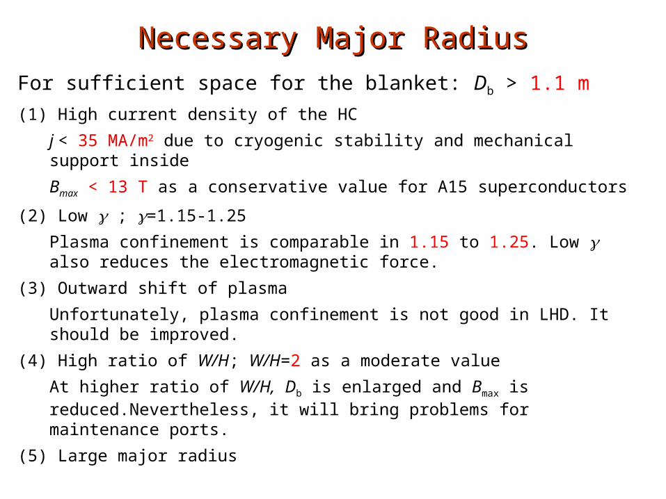
Necessary Major RadiusNecessary Major Radius
For sufficient space for the blanket: Db > 1.1 m
(1) High current density of the HC
j < 35 MA/m2 due to cryogenic stability and mechanical support inside
Bmax < 13 T as a conservative value for A15 superconductors
(2) Low ; =1.15-1.25
Plasma confinement is comparable in 1.15 to 1.25. Low also reduces the electromagnetic force.
(3) Outward shift of plasma
Unfortunately, plasma confinement is not good in LHD. It should be improved.
(4) High ratio of W/H; W/H=2 as a moderate value
At higher ratio of W/H, Db is enlarged and Bmax is reduced.Nevertheless, it will bring problems for maintenance ports.
(5) Large major radius
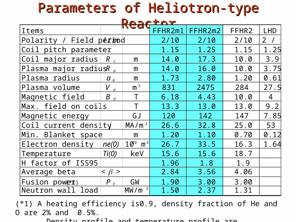
Parameters of Heliotron-type ReactorParameters of Heliotron-type ReactorItems FFHR2m1 FFHR2m2 FFHR2 LHDPolarity / Field period l / m 2/10 2/10 2/10 2 / 10Coil pitch parameter 1.15 1.25 1.15 1.25Coil major radius R c m 14.0 17.3 10.0 3.9Plasma major radius R p m 14.0 16.0 10.0 3.75Plasma radius a p m 1.73 2.80 1.20 0.61Plasma volume V p m3 831 2475 284 27.5Magnetic field B 0 T 6.18 4.43 10.0 4Max. field on coils T 13.3 13.0 13.0 9.2Magnetic energy GJ 120 142 147 7.85Coil current density j MA/m2 26.6 32.8 25.0 53Min. Blanket space m 1.20 1.10 0.70 0.12Electron density ne(0) 1019 m-3 26.7 33.5 16.3 1.64Temperature Ti(0) keV 15.6 15.6 18.7H factor of ISS95 1.96 1.8 1.9Average beta < > 2.84 3.56 4.06Fusion power (*1) P F GW 1.90 3.00 3.00Neutron wall load MW/m2 1.50 2.37 1.31
(*1) A heating efficiency is0.9, density fraction of He and O are 2% and 0.5%. Density profile and temperature profile are parabolic.
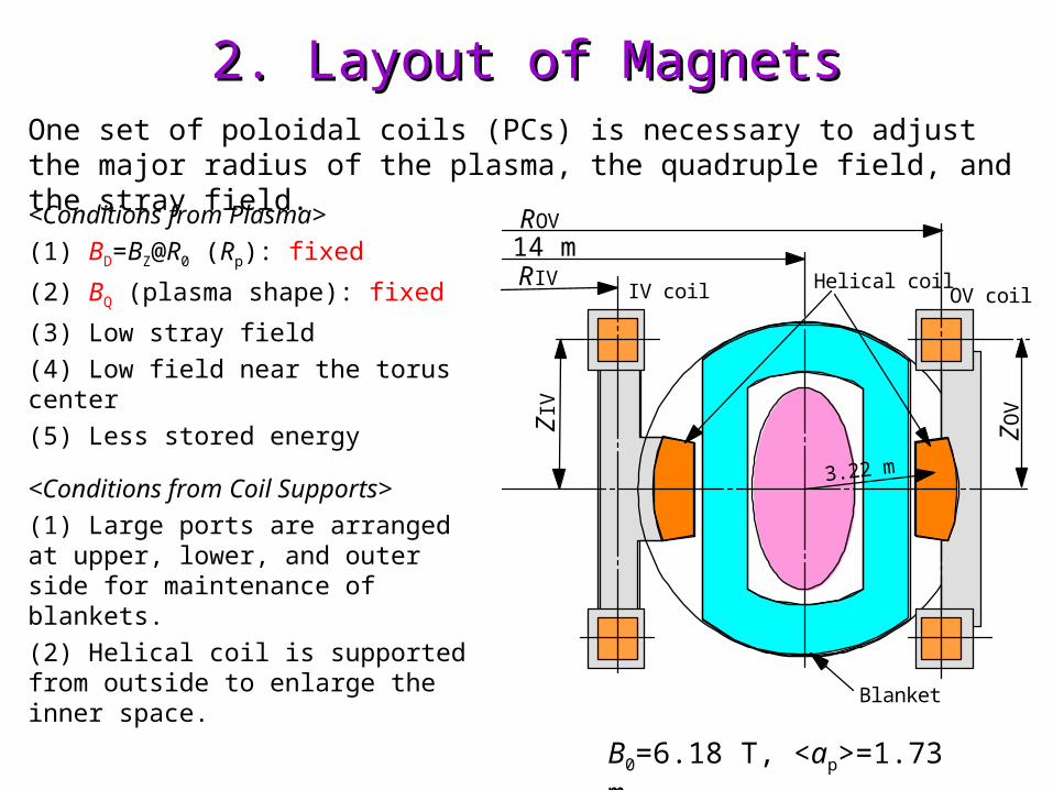
2. Layout of Magnets2. Layout of Magnets
<Conditions from Plasma>
(1) BD=BZ@R0 (Rp): fixed
(2) BQ (plasma shape): fixed
(3) Low stray field
(4) Low field near the torus center
(5) Less stored energy
<Conditions from Coil Supports>
(1) Large ports are arranged at upper, lower, and outer side for maintenance of blankets.
(2) Helical coil is supported from outside to enlarge the inner space.
One set of poloidal coils (PCs) is necessary to adjust the major radius of the plasma, the quadruple field, and the stray field.
14 m
3.22 m
IV coil OV coilHelical coil
Blanket
ROV
RIV
ZO
V
ZIV
B0=6.18 T, <ap>=1.73 m
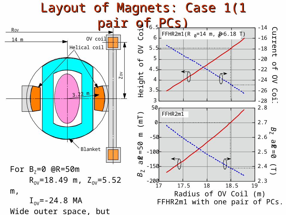
Layout of Magnets: Case 1(1 pair of PCs)Layout of Magnets: Case 1(1 pair of PCs)
14 m
3.22 m
ROV
OV coil
Helical coil
Blanket
ZO
V
For BZ=0 @R=50m ROV=18.49 m, ZOV=5.52 m, IOV=-24.8 MAWide outer space, but WB=152 GJ, BZ(R=0)=2.4 T
3
3.5
4
4.5
5
5.5
6
6.5
-28
-26
-24
-22
-20
-18
-16
-14
Hei
ght o
f OV
Coi
l (m
)
Current of O
V C
oil (MA
)
FFHR2m1(R0=14 m, B0=6.18 T)
-200
-150
-100
-50
0
50
2.3
2.4
2.5
2.6
2.7
2.8
17 17.5 18 18.5 19
BZ a
t R=
50 m
(m
T)
BZ at R
=0 (T
)
Radius of OV Coil (m)FFHR2m1 with one pair of PCs.
FFHR2m1
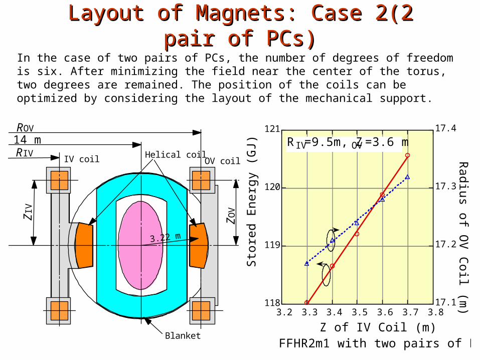
Layout of Magnets: Case 2(2 pair of PCs)Layout of Magnets: Case 2(2 pair of PCs)
In the case of two pairs of PCs, the number of degrees of freedom is six. After minimizing the field near the center of the torus, two degrees are remained. The position of the coils can be optimized by considering the layout of the mechanical support.
118
119
120
121
17.1
17.2
17.3
17.4
3.2 3.3 3.4 3.5 3.6 3.7 3.8
Sto
red
Ene
rgy
(GJ)
Radius of O
V C
oil (m)
Z of IV Coil (m)
RIV=9.5m, ZOV=3.6 m
FFHR2m1 with two pairs of PCs.
14 m
3.22 m
IV coil OV coilHelical coil
Blanket
ROV
RIV
ZO
V
ZIV
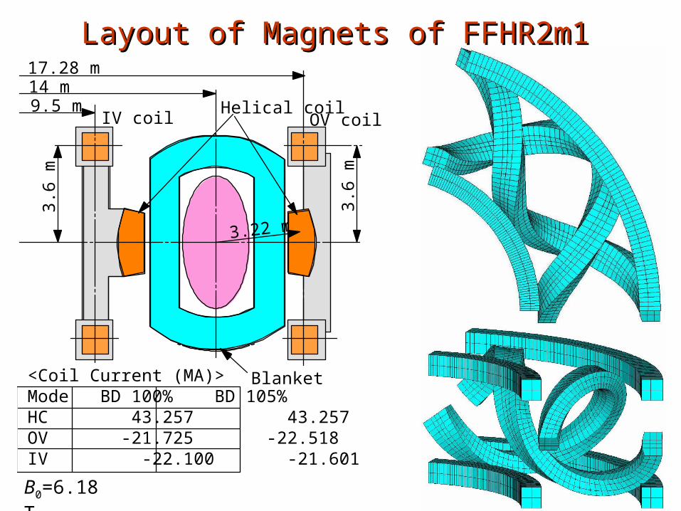
Layout of Magnets of FFHR2m1Layout of Magnets of FFHR2m1
<Coil Current (MA)> Mode BD 100% BD 105% HC 43.257 43.257 OV -21.725 -22.518 IV -22.100 -21.601
9.5 m14 m
3.22 m
17.28 m3.
6 m
IV coil OV coilHelical coil
3.6
m
Blanket
B0=6.18 T
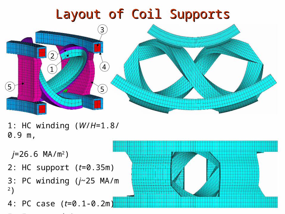
Layout of Coil SupportsLayout of Coil Supports
2
1
3
4
55
1: HC winding (W/H=1.8/0.9 m, j=26.6 MA/m2)
2: HC support (t=0.35m)
3: PC winding (j~25 MA/m2)
4: PC case (t=0.1-0.2m)
5: Inner and Outer support (t~0.5 m)
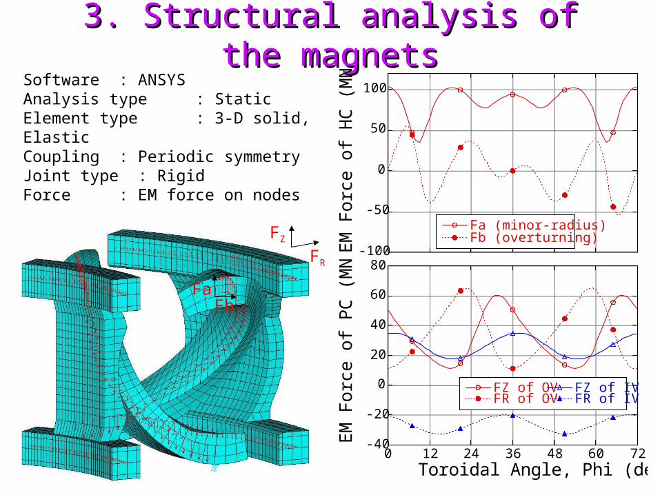
3. Structural analysis of the magnets3. Structural analysis of the magnetsSoftware : ANSYSAnalysis type: StaticElement type : 3-D solid, ElasticCoupling : Periodic symmetryJoint type : RigidForce : EM force on nodes
-100
-50
0
50
100
Fa (minor-radius)Fb (overturning)
EM
For
ce o
f H
C (
MN
/m)
-40
-20
0
20
40
60
80
0 12 24 36 48 60 72
FZ of OVFR of OV
FZ of IVFR of IV
EM
For
ce o
f P
C (
MN
/m)
Toroidal Angle, Phi (deg)
FZ
FR
FaFb
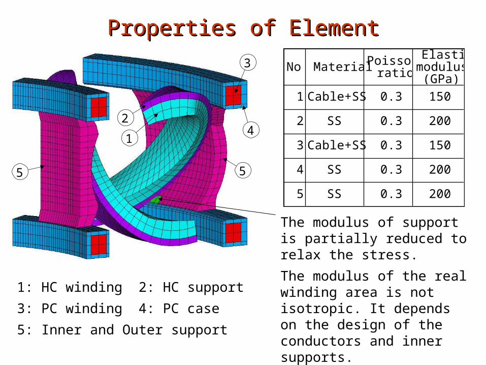
Properties of ElementProperties of Element
2
1
3
4
55
1: HC winding 2: HC support
3: PC winding 4: PC case
5: Inner and Outer support
No Material Poissonratio
Elasticmodulus
(GPa)
1 Cable+SS 0.3 150
2 SS 0.3 200
3 Cable+SS 0.3 150
4 SS 0.3 200
5 SS 0.3 200
The modulus of support is partially reduced to relax the stress.
The modulus of the real winding area is not isotropic. It depends on the design of the conductors and inner supports.
–> Future work
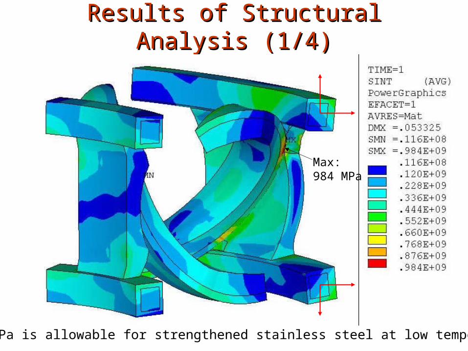
Results of Structural Analysis (1/4)Results of Structural Analysis (1/4)
1,000 MPa is allowable for strengthened stainless steel at low temperature.
Max: 984 MPa
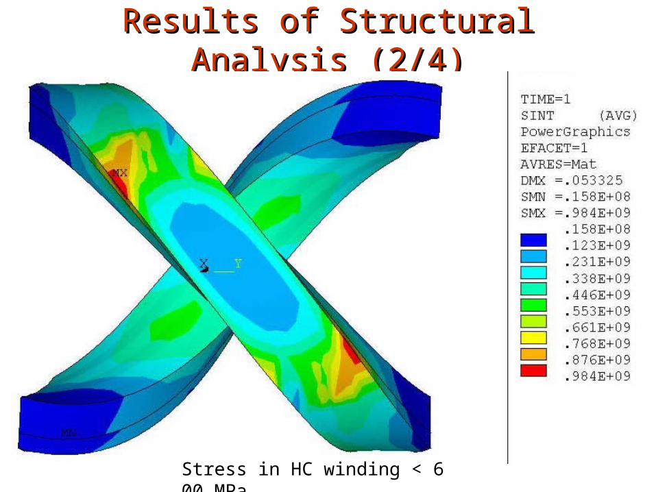
Results of Structural Analysis (2/4)Results of Structural Analysis (2/4)
Stress in HC winding < 600 MPa
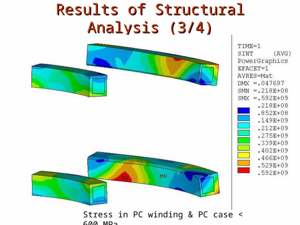
Results of Structural Analysis (3/4)Results of Structural Analysis (3/4)
Stress in PC winding & PC case < 600 MPa
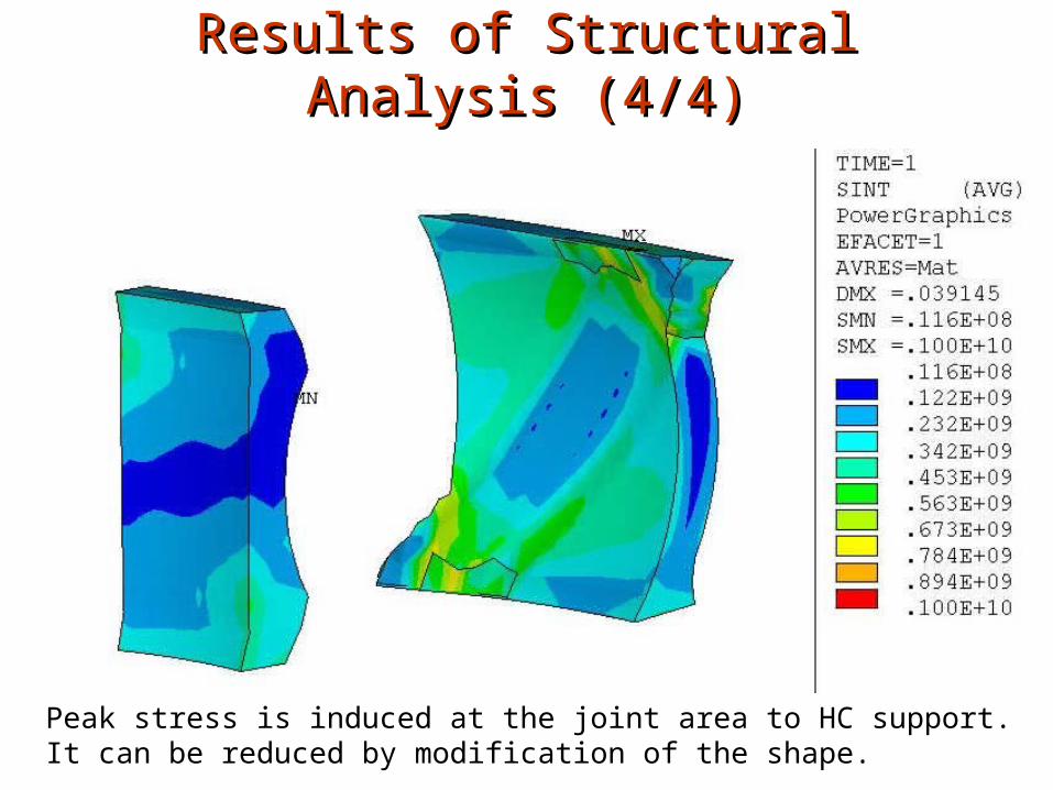
Results of Structural Analysis (4/4)Results of Structural Analysis (4/4)
Peak stress is induced at the joint area to HC support. It can be reduced by modification of the shape.
SummarySummary
(1) Two sets of poloidal coils (PCs) make it possible to reduce the magnetic field near the center and stored energy.
(2) The position of PCs is not optimized yet. Slightly larger radius of OV coils will reduce the peak stress.
(3) The supporting structure with wide ports at upper, lower, and outer area was proposed. The feasibility of this concept was confirmed by structural analysis.
(4) Future works arenew design of winding with high rigidity and strength,further optimization of supporting structure ( < 900 MPa),and conceptual design of remote maintenance of blankets.