Study on Heel Stabilization for Cruise Ship by using … on Heel Stabilization for Cruise Ship by...
18
Study on Heel Stabilization for Cruise Ship by using Active Fin and Anti-Rolling Tank Jae-Han Kim and Yonghwan Kim Department of Naval Architecture and Ocean Engineering, Seoul National University, Korea International Research Exchange Meeting of Ship and Ocean Engineering in Osaka 22 December 2012
Transcript of Study on Heel Stabilization for Cruise Ship by using … on Heel Stabilization for Cruise Ship by...

Study on Heel Stabilization for Cruise Ship by using Active Fin and Anti-Rolling Tank
Jae-Han Kim and Yonghwan Kim
Department of Naval Architecture and Ocean Engineering,
Seoul National University, Korea
International Research Exchange Meeting of Ship and Ocean Engineering in Osaka
22 December 2012

International Research Exchange Meeting of Ship and Ocean Engineering in Osaka
Wind-Induced Heel of Cruise Ship
• Wind-induced heel of cruise ship‒ Large superstructure of cruise ship makes her vulnerable to
lateral wind load.
‒ Wind-induced heel of cruise ship is considered in the seakeeping
point of view.
‒ Heel stabilization is recommended to improve passenger comfort
and seakeeping performance.
• Prediction of heel moment‒ Wind-induced heel moment to the ship is computed numerically.
‒ Wind speed profile: DNV Recommended Practice C205 (October
2010)
‒ Calculation of heel moment (Fujiwara & Ueno, 2006)
‒ Heel moment coefficient from wind tunnel experiment in
Fincantieri (Serra, 2002)
• Stabilization of heel effect‒ Actuator: Stabilizing fin, anti-rolling tank (U-tube tank)
‒ Linear optimal control algorithm: LQG
2
Wind
Wind-induced heel of cruise ship

International Research Exchange Meeting of Ship and Ocean Engineering in Osaka
Computational Program
• WISH-CRUISE‒ Computational methods of heel moment and motion stabilization integrate to the program WISH-CRUISE.
‒ WISH-CRUISE is extension based on WISH (computer program for nonlinear wave induced load and ship motion) which
is developed in Seoul National University.
‒ Assessment of seakeeping performance of cruise ship in time domain can be carried out by using the program WISH-
CRUISE.
3
WISH(Ship motion analysis
in time domain)
Motion control Comfort analysis
Added resistance Seakeeping analysis
Wind-inducedheel moment
WISH-CRUISE
Computationresult

International Research Exchange Meeting of Ship and Ocean Engineering in Osaka 4
Prediction of Wind-Induced Heel
I. Model cruise ship
II. Wind speed profile model
III. Computation of heel moment

International Research Exchange Meeting of Ship and Ocean Engineering in Osaka
Model Cruise Ship
• Similar cruise ships to model cruise ship‒ Caribbean Princess, computational model cruise ship,
experimental model cruise ship
‒ Specification and shape of superstructure are necessary to
obtain the heel moment accurately.
→ Superstructure of Caribbean Princess is considered in the
present study.
5
Model Cruise Ship Caribbean Princess
Length (LBP) 242 m 242 m
Breadth 36 m 36 m
Depth 8.3 m 8.4 m
Displacement 51,000 ton 52,000 ton
Model cruise ship of Fujiwara & Ueno (2006)
Caribbean Princess (Fincantieri, 2004)
Test model No. 1852 (1/125, Fincantieri)
It seems to be sister ships
Solution panels of model cruise ship

International Research Exchange Meeting of Ship and Ocean Engineering in Osaka
Parameters for Computation of Wind Load
• Coordinate system for numerical computation‒ Apparent wind velocity is computed from vector summation of
true wind velocity and forward speed of ship.
• Definition of parameters‒ Parameters for wind load computation are obtained from
specifications of the superstructure of Caribbean Princess.
6
Definition of parameters for calculation
Length overall, LOA 275.7 m
Breadth, B 36.0 m
Frontal projected area, AF 1738.3 m2
Lateral projected area, AL 9093.0 m2
Height of top of superstructure, HBR 46.2 m
Height from calm water surface to center of lateral projected area C, HC
17.3 m
Mean height of the ship (equal to AL/LOA), HL
33.0 m
air density (kg/m3), ρA 1.2754 kg/m3
Lateral view of model cruise ship
Frontal view of model cruise ship
Coordinate system

International Research Exchange Meeting of Ship and Ocean Engineering in Osaka
Wind Speed Profile
• Wind speed profile for heel moment‒ Logarithmic wind speed profile model
‒ DNV (2010), “Wind loads”, Recommended Practice C205, Section 5
‒ The 10 minutes mean wind speed at 10m height above the still water
level is to be used as a wind parameter U(H).
κ: surface friction coefficient
ka = 0.4: von Karman’s constant
z: altitude
z0: terrain roughness parameter
‒ Terrain roughness parameter z0
‒ DNV RP C205, Table 2.1: to consider difference between open sea
and coastal area
‒ Constant terrain roughness parameter
z0 = 0.0001 (for open sea)
z0 = 0.001 (for coastal areas with onshore wind)
7
11 lna
zU z U Hk H
2
2
0
ln
ak
Hz
Definition of wind speed profile model
0 2 4 6 8 10 12 140
5
10
15
20
25
30
35
40
45
50
Wind speed (m/s)
Alti
tude
(m)
Wind speed profile
open sea with wavescoastal areas with onshore wind
Computed wind speed profile at U(H) = 10 m/s
z
U(z)
z = z0
z = 0
U(H)
H = 10m
The height of model cruise ship is over 40m, therefore, difference should be considered.

International Research Exchange Meeting of Ship and Ocean Engineering in Osaka
Heel Moment
• Prediction of heel moment‒ Fujiwara, T. and Ueno, M. (2006), Cruising performance of a large
passenger ship in heavy sea, Proceedings of 16th ISOPE, USA
‒ Regression analysis of wind-tunnel experimental results has been
carried out.
‒ Estimated formulation of heel moment by wind load
8
A H AK A A L LK C C q A H
( )
H
AK A
A
L
L
q
whereC heel effect coefficientC heel moment coefficient
heel angleapparent relative wind direction
A lateral projected areaH mean height of the shipk empirical parameter
From experimental resultFrom estimated formula
2 2 2
2 2 2
1 1 12 2 2
1 1 12cos 12 2 2
LL
LL
A AA A q T A q T
HL H
AA q T A q A T
HL H
pressure in the actual sea wind condition
q U k U dz k UH
U k U dz k UH
Calculation of pressure component by wind load
x
x
x
x
xx x x x x x x x x
x
x
x
x
xRelative wind direction, A (deg)
Hee
lmom
ent(
Nm
)0 30 60 90 120 150 1800
5E+07
1E+08
1.5E+08
2E+08
2.5E+08
3E+08
Beaufort No.5 (10 m/s)Beaufort No.8 (20 m/s)Beaufort No.11 (30 m/s)x
Heel moment by wind direction
Wind speed (m/s)
Alti
tude
(m)
0 10 20 30 400
10
20
30
40
50Beaufort No.5 (10 m/s)Beaufort No.8 (20 m/s)Beaufort No.11 (30 m/s)
Computed wind profile for prediction of heel moment (open sea)

International Research Exchange Meeting of Ship and Ocean Engineering in Osaka
Coefficients for Heel Prediction: CH, CAK
• Heel effect coefficient: CH
‒ Serra, A. (2002), Experimental wind tunnel tests on large
passenger ships, Report of CETENA Research Plan 2002
‒ Heel moment variation by heel angle
‒ Wind tunnel experiment using modern cruise ship model by
Fincantieri: Model No. 1852 (Caribbean Princess)
• Heel moment coefficient: CAK
‒ Heel moment variation by apparent wind direction
‒ Heel moment coefficient
9
0.00738 1.0 20 0 deg0.00757 1.0 0 20 degH
forC
for
0.821
0.0737 0.097
0.500 0.097
C CAY
OA OAAK A
CAY
OA
H HC forL L
CHC forL
,
:AY A CF YLI
C
C C C lateral wind force coefficient
H height from waterline to center of lateral projected area m
Heel moment by heel angle(experiment, 1/125)
Heel angle (deg)
MY
(Nm
)
-30 -20 -10 0 10 20 306
8
10
12
14
Test Model No. 1852Test Model No. 2036
A
Coe
ff.
0 30 60 90 120 150 1800
0.2
0.4
0.6
0.8
1
1.2
1.4
CAYCCFCYLI
lift
drag
lift+drag
Lateral wind force coefficient, CAY

International Research Exchange Meeting of Ship and Ocean Engineering in Osaka 10
Analysis of Heel Stabilization
I. Stabilization using stabilizing fin
II. Stabilization using U-tube tank

International Research Exchange Meeting of Ship and Ocean Engineering in Osaka
Controller Design: Stabilizing Fin
• Controller design of stabilizing fin‒ State-space equation is derived from equation of roll motion to
apply the linear optimal control algorithm LQR (linear quadratic
regulator)
‒ Equation of roll motion
‒ Effective angle of attack (lift force)
‒ State-space equation
11
22
44 44 044 ,44
44 ,44 44 ,44
0 10 01 cos1 12
S w Y w YPL
Saa a
V u z l v ldCc b Sd I II I I I
Control input
Fin angle
44 ,44 44 44( )a Ext FinI I b c M M
Directions of lift force and drag force
1tan Y X wE
S w
z l l vV u
Effects of ship motion and waveFin inclination by controller
• Stabilizing moment is calculated from lift and drag forces and applied into motion simulation instantaneously.
• Hydrodynamic effects of lifting surface such as stall and free surface effect are also considered.
• Two stabilizing fins are controlled simultaneously to reduce heel and roll motion.• LQR controller is applied to determine the control inputs of two stabilizing fins in real time.

International Research Exchange Meeting of Ship and Ocean Engineering in Osaka
Motion Stabilization: Control Algorithm
• Optimal control algorithm: LQR‒ LQR (linear quadratic regulator) control is an
optimal control. Optimal control input u should
minimize performance index J.
‒ Control performance is tuned by adjusting the
state and control input weight matrices
‒ Control input u is obtained by solving algebraic
Riccati equation.
• LQG (linear quadratic Gaussian)‒ Application of LQG controller can make the
robustness of the designed controller better by
reducing the noise effect, so that the overall
performance of the active stabilizing fin improves.
0 ( ) ( ) ( ) ( )T Ts sJ x t x t u t u t dt Q R
state weight matrixwhere
control input weight matrix
QR
• State observer: Kalman Filter Kalman filter is an optimal state observer based on the
current and past measurement (Kalman, 1960).
Augmented state space equation includes the process and measurement noises.
State observer based on Kalman filter
State observer(Kalman Filter)
Controller (LQR)
Plant(Motion analysis)
Control input
Measured output
Estimated states
Disturbance
Noise
r y
ˆ( ) :
:x t estimated stateL observer gain Kalman filter gain
1: ( ) ( )TControl input u t R B P x t
LQR + Kalman filter → LQG (linear quadratic Gaussian)
12Diagram of designed controller
0 0
ˆ ˆ ˆ( ) ( ) ( ) ( ( ) ( ))( )
x t Ax t Bu t L y t Cx tx t x
1 0T TPA A P PBR B P Q
International Research Exchange Meeting of Ship and Ocean Engineering in Osaka
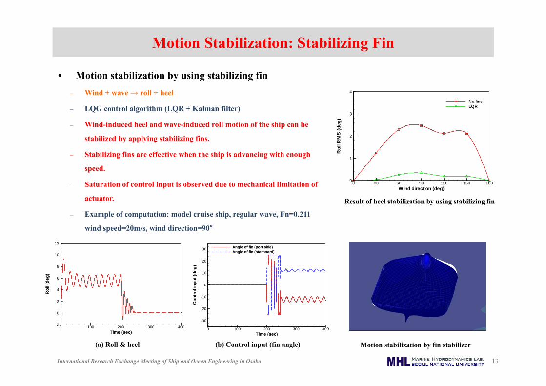
Motion Stabilization: Stabilizing Fin
• Motion stabilization by using stabilizing fin‒ Wind + wave → roll + heel
‒ LQG control algorithm (LQR + Kalman filter)
‒ Wind-induced heel and wave-induced roll motion of the ship can be
stabilized by applying stabilizing fins.
‒ Stabilizing fins are effective when the ship is advancing with enough
speed.
‒ Saturation of control input is observed due to mechanical limitation of
actuator.
‒ Example of computation: model cruise ship, regular wave, Fn=0.211
wind speed=20m/s, wind direction=90°
13
Result of heel stabilization by using stabilizing fin
(a) Roll & heel (b) Control input (fin angle) Motion stabilization by fin stabilizer
Time (sec)
Rol
l(de
g)
0 100 200 300 400-2
0
2
4
6
8
10
12
Time (sec)
Con
troli
nput
(deg
)
0 100 200 300 400
-30
-20
-10
0
10
20
30 Angle of fin (port side)Angle of fin (starboard)
Wind direction (deg)
Rol
lRM
S(d
eg)
0 30 60 90 120 150 1800
1
2
3
4
No finsLQR

International Research Exchange Meeting of Ship and Ocean Engineering in Osaka
Anti-Rolling & Heeling Tank: U-tube Tank
• Heel stabilization by using U-tube tank‒ U-tube tank is usually considered as anti-rolling tank.
‒ U-tube tank can also be actuated as anti-heeling tank.
‒ Internal fluid height in the tank can be controlled by
using hydraulic pump or compressed air.
‒ In the present study, pressure of actuator is considered
as a control input.
• Dimension of tank‒ In general, volume of internal fluid in the tank is
determined about 1~2% of ship displacement.
‒ In the present study, arbitrary dimension of the tank is
applied to perform the simulation.
14
Dimension of U-tube tank
Density of fluid in the tank 1025 kg/m3
Fluid height in the reservoir (hr) 3.0 m
Width of vertical reservoir (wr) 2.0 m
Height of horizontal duct (hd) 1.0 m
Length between two reservoir (w) 30 m
Volume of internal fluid 860 m3
G
Starboard
Equilibrium level
Port
wr
hd
w/2
τ(t)
hr y
z
r
rd
w/2

International Research Exchange Meeting of Ship and Ocean Engineering in Osaka
Controller Design: Active U-tube Tank
• State-space model to design the controller of U-tube tank‒ Controller of U-tube tank is also designed by adopting the LQG algorithm
‒ Equation of motion: roll motion and U-tube tank
‒ Derivation of state-space equation to apply the LQR control
15
(Roll motion of the ship)
(Height variation of internal fluid in the tank)
44 ,44 4 44 4 44 4 4 4a ExtI I x b x c x a c F
4 4 4 4 Ta b c a x c x F r
Moment by tank
Control input
4 4 4 44444 4
4
4
4 44 4 44 4 44
44 ,44 44 ,44 44 ,44
1 1
1 0 0 0
1 1
0 0 1 0a a a
a c a b a cb c cA A a a A A ax
x
a b a c b a cc cB B BB I I I I I I
4
4
4
4
44 ,44
1
00
0 0
T Ext
a
a rx Aa Ax
F FarB I IB
4 4 4 4
44 ,4444 ,44
,aa
a a a awhere A I I B aa I I
Control inputSystem matrix for fluid level in the tank
• Stabilizing moment is calculated from height variation of internal fluid in the U-tube tank and applied into motion simulation instantaneously.
• Dynamics of internal fluid in the tank should be considered to obtain the stabilizing moment from the control input.
• Designed controller by using state-space equation integrates to the WISH-CRUISE.• Control input from U-tube tank is applied simultaneously to reduce heel and roll motion.

International Research Exchange Meeting of Ship and Ocean Engineering in Osaka
Motion Stabilization: Active U-tube Tank
• Motion stabilization by using active U-tube tank‒ Wind + wave → roll + heel
‒ LQG control algorithm (LQR + Kalman filter)
‒ Wind-induced heel and wave-induced roll motion of the ship can be
stabilized by applying U-tube tank.
‒ Motion stabilization by using tank can be effective regardless of
forward speed of the ship.
‒ Performance of stabilization is dependent on the dimension of tank
and capacity of actuator.
‒ Example of computation: model cruise ship, regular wave, wind
speed=20m/s, wind direction=90°
16
Result of heel motion stabilization by using U-tube tank (regular waves)
(a) Roll & heel (b) Control input (tank fluid height) Motion stabilization by active U-tube tank
Time (sec)
Rol
l(de
g)
0 100 200 300 400-2
0
2
4
6
8
10
12
Time (sec)
Tank
leve
l(de
g)
0 100 200 300 400-5
0
5
10
15
20
Wind direction (deg)
Rol
lRM
S(d
eg)
0 30 60 90 120 150 180
0
1
2
3
4
No tankLQR
International Research Exchange Meeting of Ship and Ocean Engineering in Osaka
Conclusions
• Computational methods to predict the wind-induced heel and to stabilize the motion of cruise
ship are developed.
• Heel moment by wind load is computed using the estimated formulation. In this procedure,
heel effect coefficient is corrected using another wind tunnel experimental result.
• Motion stabilizations by using stabilizing fin or active U-tube tank are considered based on
linear optimal control algorithm LQG.
• These computational methods integrate to the time-domain seakeeping analysis program for
cruise ship, called WISH-CRUISE.
• From result of numerical computations, it is observed that wind-induced heel of cruise ship
can be reduced effectively by applying active fins or active U-tube tank.
• For more realistic simulation, mechanical limitation of control actuator will be considered
appropriately.
17

International Research Exchange Meeting of Ship and Ocean Engineering in Osaka
Thank You
18