Study on Development in Medical Bone Regeneration and ...
143
Study on Development in Medical Bone Regeneration and Biodegradable of Mg-Based Alloys for Biomedical Applications 骨の再生医療における Mg 基合金の開発と 生分解性に関する研究 Haijian Wang Saitama Institute of Technology August, 2020
Transcript of Study on Development in Medical Bone Regeneration and ...

Study on Development in Medical Bone Regeneration and Biodegradable of Mg-Based
Alloys for Biomedical Applications
骨の再生医療における Mg 基合金の開発と
生分解性に関する研究
Haijian Wang
Saitama Institute of Technology
August, 2020

I
Contents Abstract ................................................................................................................................. i
Chapter 1 Introduction ......................................................................................................... 1
1.1 Biomedical Materials ............................................................................................. 1
1.2 Biomedical metallic materials ................................................................................ 3
1.2.1 Stainless steel bone reinforcement plate ...................................................... 4
1.2.2 Bone reinforcement plate of CoCr alloy ...................................................... 6
1.2.3 Ti and Ti alloy .............................................................................................. 8
1.3 Biodegradable magnesium alloy .......................................................................... 10
1.3.1 Degradation characteristics ...................................................................... 11
1.3.2 Mechanical properties ............................................................................... 13
1.3.3 Biocompatibility ......................................................................................... 14
1.3.4 Advantages and disadvantages in biomedical applications ...................... 15
1.4 Modification of magnesium alloy materials ......................................................... 17
1.4.1 Surface modification .................................................................................. 17
1.4.2 Alloying of bone reinforcement materials ................................................. 19
1.4.3 Research status of magnesium alloys......................................................... 20
1.5 The purpose of this research ................................................................................. 21
1.6 References ............................................................................................................ 24
Chapter 2 The microstructure, composition design and experiment methods of Mg-based
alloy ................................................................................................................................... 31
2.1 The microstructure of Mg-based alloy design ...................................................... 31
2.1.1 The microstructure of amorphous / nanocrystalline alloy ......................... 31
2.1.2 Rapid solidification in producing amorphous / nanocrystalline alloys ..... 32
2.1.3 Rapid solidification of twin roll casting technique .................................... 33
2.2 The composition of Mg-based alloy design ......................................................... 35
2.2.1 The glass forming ability rules in alloys .................................................... 35
2.2.2 Compositions of the alloys ......................................................................... 36
2.3 Preparation of Mg-based alloys with TRC ........................................................... 39

II
2.4 Microscopic characterization ............................................................................... 41
2.5 Preparation of TEM foils by focused ion beam (FIB) milling ............................. 41
2.6 Electrochemical characterization ......................................................................... 42
2.6.1 Introduction of Electrochemical Workstation ............................................ 42
2.6.2 Tafel linear extrapolation .......................................................................... 44
2.6.3 Electrochemical impedance spectroscopy (EIS) ........................................ 45
2.7 Animals tests ........................................................................................................ 46
2.7.1 Implant method .......................................................................................... 46
2.7.2 Experimental animals ................................................................................ 47
2.7.3 Surgical procedure ..................................................................................... 47
2.8 Methods of in vivo test analysis ........................................................................... 49
2.9 Concluding remarks ............................................................................................. 50
2.10 References .......................................................................................................... 51
Chapter 3 Preparation and characterization of Mg-RE by TRC for biomedical application
........................................................................................................................................... 53
3.1 Introduction .......................................................................................................... 53
3.2 Materials and methods.......................................................................................... 55
3.3 Results and discussion .......................................................................................... 58
3.3.1 Microstructure characteristic .................................................................... 58
3.3.2 Electrochemical measurements ................................................................. 64
3.3.3 Immersion test ............................................................................................ 68
3.3.4 In vivo implantation ................................................................................... 71
3.4 Concluding remarks ............................................................................................. 74
3.5 References ............................................................................................................ 75
Chapter 4 In vivo degradation behaviour and bone response of cast-rolled alloy in rat
femoral model .................................................................................................................... 78
4.1 Introduction .......................................................................................................... 78
4.2 Materials and Methods ......................................................................................... 80
4.2.1 Material preparation and characterization ............................................... 80
4.2.2 Implant method .......................................................................................... 82

III
4.2.3 Electrochemical characterization .............................................................. 82
4.2.4 Micro-CT analysis ..................................................................................... 82
4.2.5 In vivo corrosion assessment ..................................................................... 83
4.2.6 Histological observation ............................................................................ 83
4.2.7 Statistical analysis ..................................................................................... 83
4.3 Results and discussion .......................................................................................... 84
4.3.1 Microstructures analysis ............................................................................ 84
4.3.2 In vitro corrosion properties ...................................................................... 91
4.3.3 Animal test ................................................................................................. 93
4.3.4 Degradable implant cross-sectional examination ..................................... 93
4.3.5 Bone response and histological examination ............................................ 97
4.4 Concluding remarks ........................................................................................... 101
4.5 References .......................................................................................................... 102
Chapter 5 Influence of casting speed on microstructure and biodegradation properties of
Mg-RE alloy .................................................................................................................... 108
5.1 Introduction ........................................................................................................ 108
5.2 Experimental methods ........................................................................................ 110
5.2.1 Materials preparation .............................................................................. 110
5.2.2 Electrochemical tests ............................................................................... 111
5.2.3 In vivo bone implantation ........................................................................ 111
5.2.4 Micro-CT and histological assessments .................................................. 112
5.2.5 In vivo degradation tests .......................................................................... 112
5.2.6 Statistical analysis ................................................................................... 112
5.3 Experimental results ........................................................................................... 113
5.3.1 Investigation of microstructures .............................................................. 113
5.3.2 Electrochemical characterization ............................................................ 116
5.3.3 Micro-CT and histological characterization ........................................... 118
5.3.4 In vivo degradation .................................................................................. 120
5.4 Discussion of experimental results ..................................................................... 121
5.4.1 Microstructure analyses ........................................................................... 121

IV
5.4.2 Electrochemical test analyses .................................................................. 123
5.4.3 In vivo degradation property analyses .................................................... 125
5.5 Concluding remarks ........................................................................................... 127
5.6 References .......................................................................................................... 128
Chapter 6 Conclusions ..................................................................................................... 131
Related publications......................................................................................................... 134
Acknowledgements.......................................................................................................... 136

Abstract
i
Abstract
Nowadays, the approved and commonly metallic biomaterials include stainless steels,
titanium alloys, cobalt-chromium-based alloys and noble metals. The limitations of these
current metallic biomaterials are the possible release of toxic metallic ions or particles
through corrosion or wear processes and the long-term biological incompatibility caused
by interactions between tissues and permanent metallic implants. Magnesium (Mg) alloys
are considered as the new generation of biomedical implant materials due to their good
biocompatibility, biodegradability and excellent mechanical properties. This paper reports
an exploratory study on the biodegradation of Mg-RE (RE - rare-earth elements) alloy
sheets with fine grain around amorphous zone produced by vertical twin roll casting (TRC)
and its interaction with rat femur was observed by micro-CT, which provides a novel
method of crystalline/amorphous structuring alloy design and an important evidence of the
potential use of Mg-RE for future surgical implant applications.
A new type of Mg-RE (Ce, La) sheets were prepared by vertical (TRC) technology.
The microscopic characterization experiments show that the crystal structure is crystalline
phase containing amorphous phase. Electrochemical experiments and immersion testing
both showed that Mg-RE (La,Ce) sheet with TRC has a better corrosion resistance than
master alloy of Mg-RE alloys, and a uniform corrosion layer on the sheet surface. In vivo
tests show that Mg-RE sheets have better biocompatibility and induce new bone formation.
Mg-RE and AZ31 sheets were prepared by vertical (TRC) technology under identical
casting conditions. The microstructure characterization showed that the Mg-RE exhibited
a higher amorphous forming ability than the AZ31. Moreover, the results of
electrochemical impedance spectroscopy (EIS) and potentiodynamic polarization indicated
that the Mg-RE sheets displayed a higher corrosion resistance compared with the AZ31
sheets. Additionally, the Ti, Mg-RE and AZ31 sheet implants were immobilized and
implanted in a rat femur model to observe degradation behavior during 16 weeks. In vivo
tests showed that no significant change in the femur surrounding the Ti group, which
excluded the external factor that the new bone formation resulting from bone remodeling.

Abstract
ii
Furthermore, the Mg-RE group induced more newly formed bones, which met the
necessary conditions for the prevention of pathological fractures.
Two casting speeds of 10 rpm and 30 rpm were used in vertical twin-roll casting (TRC)
to obtain Mg-rare earth (Mg-RE) alloys. The results indicated that the roll-castings of TRC-
30-rpm exhibited a finer grain size and higher volume fraction of non-crystallization than
those in castings of TRC-10-rpm. Moreover, the results of electrochemical impedance
spectroscopy (EIS) and potentiodynamic polarization indicated that the castings of TRC-
30 rpm displayed a higher corrosion resistance compared to those in the castings of TRC-
10-rpm. Animal tests showed that a higher degree of newly formed bone tissues was
achieved by implants of TRC-30-rpm. Additionally, in vivo tests displayed that degradation
properties of the TRC-30-rpm implants were better than those of the TRC-10-rpm implants;
furthermore, the degradation layer was a two-layer structure, and P and Ca were enriched
in the outer degradation layer. In summary, these findings elucidated that casting speed has
a substantial effect on the microstructure and degradation property of Mg-based implants,
and the degradation property performs better with increased casting speed.
Keywords: Magnesium alloys, Biomedical materials, Microstructure, In vivo degradation
and bone response

Chapter 1 Introduction
1
Chapter 1 Introduction
For a long time, the biological materials, such as artificial joints and sutures, have been
implanted in body to heal damaged tissue. The artificial joints as a permanent implant
require high durability, while the sutures as a biodegradable implant are broken down and
absorbed by the body after tissue repair. In the past, the implants were usually durable and
permanent, so they had to be surgically removed after tissue repair. However, the
biodegradable materials have been developed and used as fixation materials for fractures,
such as polylactic acid materials (PLA) are used for suture and as a fixed material for
fractures in low-burden areas, thus reducing the burden of reoperation. In addition, the
calcium cyanate ceramics can also be used as the bone - free compensation materials.
However, only polymers and ceramic materials are developed, and their applications in
biomedical materials are limited. Because these biodegradable absorbent materials lack the
necessary mechanical strength, they cannot be overused in stressed areas. Therefore, it is
desirable to develop biomaterials with better mechanical and better biodegradable
properties.
In recent years, the application of magnesium (Mg) alloy in biodegradable materials
have attracted the attention of researchers and medical personnel. Mg has high specific
strength and is the lightest of the practical metal materials used as structural materials. In
addition, as Mg is a bio-essential element, the biological safety of magnesium alloys
remains high after in vivo degradation.
1.1 Biomedical Materials
Biomaterial can be made into devices that can be used to diagnose, treat or replace
tissues and organs that are weakened or completely lost due to lesions or damage [1].
Biomaterials can be natural, synthetic, or a combination of them. As early as 5000 BC,
there are records of artificial teeth being used to repair lost teeth in ancient Egypt and China.
In the 2nd century AD, there are records of artificial teeth being used as suture lines to

Chapter 1 Introduction
2
ligate wounds and prevent arterial blood loss. With the rapid development of social progress
and modern science and technology, the biomedical material industry has also entered its
rapid development stage, which plays an important role in improving people's quality of
life and guaranteeing human health. It has gradually become an emerging industry with
extremely rapid development.
Fig. 1.1 Various biomedical materials and their functions [1].
Biomedical materials can be classified into three categories according to the
biochemical reaction level of materials in physiological environment: (1) nearly inert
biological materials, (2) bioactive materials, (3) biodegradable and absorbable biological
materials. According to the traditional material composition and properties, biomedical
materials can be divided into five categories: (1) medical metal materials, (2) medical
polymer materials, (3) biological ceramic materials, (4) biological derivative materials and
(5) biomedical composite materials. Each of them account for more than 40 percent of
biomaterial application amount. Table 1-1 describes the application, advantages and
disadvantages of different types of biomaterials.

Chapter 1 Introduction
3
Table 1-1 Commonly used biomaterials [2]
Materials category Advantage Shortcoming Application
Metallic materials
(Titanium and its alloy;
CO-Cr alloy; Stainless
steel; Au; Pt, etc)
High strength; stiffness;
flexible
Easy-corrosive
high density
Joint replacement;
Bone nail and bone plate
High polymer material Good resilience;
Easy preparation
Low intensity;
Prone creep
Stylolite; blood vessel,
ear, soft tissue
Ceramics (aluminum
oxide; calcium phosphate;
base apatite, etc)
Good biocompatibility;
inert, high compression
strength
Too brittle, poor
elasticity;
Not easy processing
Surface coatings for
dental, femoral head,
dental and orthopedic
implants
Composites (carbon-
carbon composites,
carbon fiber reinforced
bone cement, etc.)
High strength, can be cut Not easy preparation Joint implants, heart
valves
1.2 Biomedical metallic materials
Metal materials are applied as biological materials due to their excellent mechanical
properties and good electrical conductivity and thermal conductivity. Because the metal
bonds in metal materials are non-directional, they can change the position of metal atoms
without destroying the crystal structure. Therefore, metal materials show the characteristics
of plastic deformation.
Due to its excellent mechanical properties and corrosion resistance, some metal
materials can be applied to replace bone screws, plates and other bone fracture repair
devices of hard tissues such as hip and knee joints, spinal fixation devices and dental

Chapter 1 Introduction
4
implants. It can also be applied to cardiovascular stents, orthodontic teeth, cochlear
implants and other places that need to play an active role in the location.
Fig. 1.2 Biomedical metallic materials.
The alloying elements in most medical metal materials are allowed in very small
amounts in the human body. Trace amounts of metallic elements can play a positive role in
human body. For example, trace amounts of Fe are very important for red blood cells, and
Co is an essential element for the synthesis of vitamin B12. However, when the intake of
these metallic elements exceeds the limit of human body, it will have many negative effects
on human physiological functions [3]. Due to the long-term existence of metal implants in
the human body and the corrosion of the internal body fluid environment, it is inevitable
that trace elements will be dissolved into the human body. Therefore, the biocompatibility
of metal elements is an important factor that metal materials as biological materials must
be concerned. At present, the widely used medical metal materials mainly include four
categories: stainless steel, titanium alloy, cobalt-based alloy and precious metal.
1.2.1 Stainless steel bone reinforcement plate
The first-generation stainless steel used in making implanted devices is 302 stainless
steel, and the stainless steel has higher strength and more excellent corrosion resistance in
the human body environment compared to the vanadium steel. The researchers found that
based on the composition of 302 stainless steel by adding a small amount of Mo (2 ~ 4
wt %) can significantly improve corrosion resistance in saline environment features. The

Chapter 1 Introduction
5
introduction of Mo in the composition stainless steel can dramatically improve the
performance of the resistance to pitting formation caused by chloride ion. In the last century
1950s, the researchers further enhance the corrosion resistance of stainless steel in the
physiological saline by reducing the concentration of the carbon element in stainless steel
(0.08 wt % decrease to 0.03 wt %), which is now known as SUS316/316L stainless steel
and its composition as shown in table 1-2. The Cr content in stainless steel must be higher
than 12 wt % to guarantee enough corrosion resistant performance, and the Ni is used to
make stainless steel in the austenite phase to keep stable at room temperature [4].
The SUS316/316L steels are austenitic stainless steels and are widely used in the
manufacture of medical implant devices. They are difficult to be strengthened by heat
treatment, but it can be strengthened by work hardening. The mechanical properties of
SUS316/316L stainless steel show in Table 1-3.
Fig. 1.3 Stainless steel bone reinforcement as bone fixed implants.
Although SUS316/316L steel has a good corrosion resistance in the biotic
environment. when the material is subject to the great stress and in the absence of oxygen
environment, it will also be corroded, such as the position where the bone nail contacts the
bone. The material will lose its fixation function due to the influence of corrosion.
Therefore, the SUS316/316L stainless steel can only be used as temporary implant device
when it is used as bone nail, bone plate and femoral head nail.

Chapter 1 Introduction
6
Table1-2 Composition of USL316L stainless steel [2]
Element C Mn P S Si Cr Ni Mo
Content
wt% <0,03 <2.00 <0.03 <0.03 <0.75 17~20 12~14 2~4
Table1-3 Mechanical properties of USL316L stainless steel for implants [2]
Condition YTS (MPa) UTS (MPa) Elongation (%) Rockwell hardness
Annealed 172 485 40 95
Cold-worked 690 860 12 -
1.2.2 Bone reinforcement plate of CoCr alloy
The CoCrMo with the as-cast state is common typical alloy. The as-cast CoCrMo alloy
has been used as a medical metal for decades. It was mainly used as a dental material in the
early stage. Recently, it has been widely used in the field of artificial joints. The deformed
CoNiCrMo alloy as a medical metal material has a relatively short use time, and it is mainly
used to make the handle of knee or hip prosthesis that to bear a large load [5,6].
American ASTM recommends four types of CoCr alloys for use in medical metallic
materials: (1) as-cast CoNiCrMo alloy, (2) morphed CoCrWNi alloy, (3) morphed
CoNiCrMo alloy, and (4) morphed CoNiCrMoWFe alloy. The chemical compositions are
shown in Table 1-4. At present, the cast CoCrMo alloy and the variable CoNiCrMo alloy
are most widely used for applications. In these two alloys, the content of Co can be as high
as 65%, and the alloy element Mo can significantly refine the grain size of the alloy. The
Cr can play a role in solid solution strengthening, on the other hand, it can also significantly
improve the corrosion resistance of the alloy [6].

Chapter 1 Introduction
7
Fig. 1.4 Bone reinforcement of Cobalt alloy.
Table 1-4 Chemical Compositions of Co–Cr alloys [9]
Element (wt. %) CoCrMo CoCrWNi CoNiCrMo CoNiCrMoWFe
Cr 27.0~30.0 19.0~21.0 19.0~21.0 18.00~22.00
Mo 5.0~7.0 - 9.0~10.5 3.00~4.00
Ni ~2.5 9.0~11.0 33.0~37.0 15.00~25.00
Fe ~0.75 ~3.0 ~1.0 4.00~6.00
C ~0.35 0.05~015 ~0.025 ~0.05
Si ~1.00 ~1.00 ~0.15 ~0.05
Mn ~1.00 ~2.00 ~0.15 ~1.00
W - 14.0~16.0 - 3.0~4.0
P - - ~0.01 ~0.01
Ti - - ~1.0 0.50~3.50
Co Balance

Chapter 1 Introduction
8
Table 1-5 Mechanical properties of Co-Cr alloys [9]
Property Cast
CoCrMo Wrought CoCrWNi
Wrought CoNiCrMo
Solution
Annealed
Cold worked
and aged
YS/MPa 450 310 240~650 1585
UTS/MPa 655 860 793~1000 1793
Elongation/% 8 10 50 35
Elastic modulus/GPa 220~234
The deformed CoNiCrMo alloy and the as-cast CoCrMo alloy have similar wear
resistance (their wear rate is 0.14mm/year). The CoNiCrMo alloy has high tensile strength
and fatigue resistance, which is more suitable for the handle of hip prosthesis. The
mechanical properties of the CoCr alloy are shown in Table 1-5. The elastic modulus of the
CoCr alloy is 220 ~ 234GPa, so this alloy is very hard with very low wear in metal-metal,
which has obvious advantages in application of metal-metal artificial joint replacement [7].
When the CoCr alloy is applied in joint replacement, the metal products result from
the metal wear and corrosion will have an adverse effect on the surrounding organ tissues.
In vitro experiment results show that the Co particles have a toxic effect on osteoclasts and
inhibit the synthesis of I-type collagen, osteocalcin and alkaline phosphatase. However, the
metal Cr and CoCr alloy particles did not show significant toxicity. The experiments of
metal extraction liquid showed that the Co and the Ni extracts had significant cytotoxicity
and significantly reduced the survival rate of cells, thus, the Cr extracts had lower
cytotoxicity than Co and Ni [8].
1.2.3 Ti and Ti alloy
In the 1930s, people began to try to apply titanium implant device for manufacturing.
It found that the titanium showed better biocompatibility, low density of titanium relative
Chapter 1 Introduction
9
to the stainless steel, the CoCrMo alloy, and its alloys (as shown in Table 1-6), and the
excellent mechanical properties (Table 1-7), which is the most significant advantage used
for making implanted devices [10, 11].
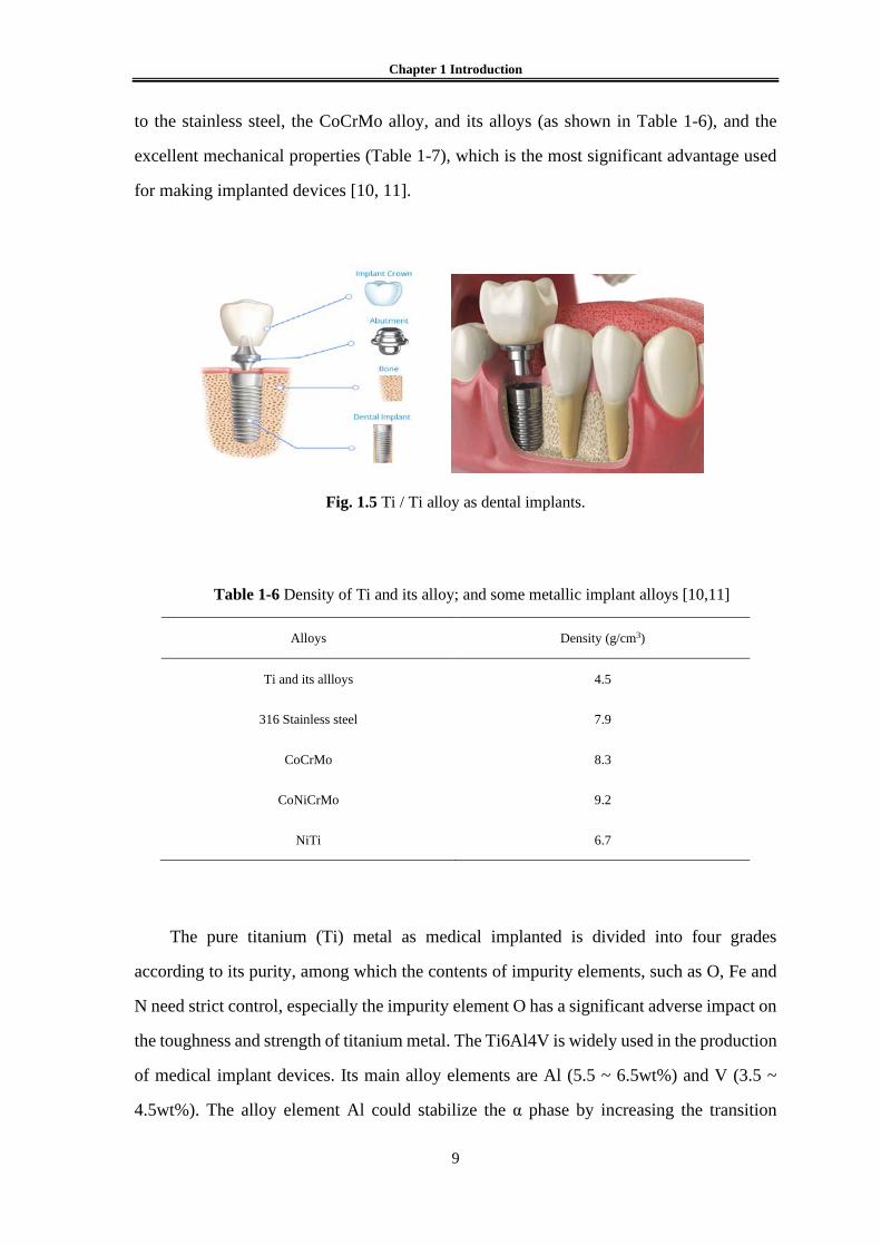
Fig. 1.5 Ti / Ti alloy as dental implants.
Table 1-6 Density of Ti and its alloy; and some metallic implant alloys [10,11]
Alloys Density (g/cm3)
Ti and its allloys 4.5
316 Stainless steel 7.9
CoCrMo 8.3
CoNiCrMo 9.2
NiTi 6.7
The pure titanium (Ti) metal as medical implanted is divided into four grades
according to its purity, among which the contents of impurity elements, such as O, Fe and
N need strict control, especially the impurity element O has a significant adverse impact on
the toughness and strength of titanium metal. The Ti6Al4V is widely used in the production
of medical implant devices. Its main alloy elements are Al (5.5 ~ 6.5wt%) and V (3.5 ~
4.5wt%). The alloy element Al could stabilize the α phase by increasing the transition

Chapter 1 Introduction
10
temperature of the α phase / β phase, while alloy element V stabilizes the β phase by
reducing the phase transition temperature of the α phase / β phase [12].
In commercial pure titanium, with the increase of impurity content, the strength
increases and the plasticity decreases of the materials. Although the strength of titanium
alloy is lower than some stainless steel and CoCr alloy, it’s the specific strength is obviously
higher than these two materials. In addition, the shear strength of titanium and its alloys is
lower, which makes them not suitable for the preparation of bone screws, bone plate and
other types of devices which need to withstand higher shear stress. The wear-resisting
performance of titanium and its alloys is poorer when it is in contact with the same material
or other metal materials, which limits the application as a medical implant metal material
[13].
Table 1-7 Mechanical properties of Ti and its alloys [9]
Properties Pure Ti
Ti6Al4V Ti13Ni13Zr Grade1 Grade2 Grade3 Grade4
UTS / MPa 240 345 450 550 860 1030
YS / MPa 170 275 380 480 795 900
Elongation / % 24 20 18 15 10 15
E / GPa 110 79
1.3 Biodegradable magnesium alloy
The biomaterials mentioned above are biologically inert, non-biodegradable, and once
implanted, they will remain permanently in the body unless removed by a second surgery.
The process of a second surgical excision will undoubtedly increase the patient's pain and
financial burden (Fig. 6) [14]. Therefore, the development trend of the new generation of
biomedical materials not only requires that the materials have good biocompatibility, but
also hopes that they can be biodegradable in vivo. Medical polymer materials have made

Chapter 1 Introduction
11
great progress in this direction. However, the polymer materials generally have low elastic
modulus and poor plasticity, which are difficult to be applied in some occasions such as
cardiovascular stent, bone nail and plate, anastomosis nail, etc. Magnesium and its alloys
are biodegradable, and it also has advantages in mechanical properties and processing
properties of metal materials [15-19].
1.3.1 Degradation characteristics
The degradation of magnesium alloy is accomplished by corrosion of magnesium
alloy in physiological environment. The corrosion process is an electrochemical reaction
process, and the total reaction formula can be written as follows [15, 20]:
Mg + H2O = Mg (OH)2 + H2 (1-1)
The electrochemical reactions can be decomposed into the following anodic oxidation
and cathodic reduction reactions:
Anode reaction: Mg → Mg2+ + 2e- (1-2)
Cathode reaction: 2H2O + 2e-→H2 + 2OH- (1-3)
Product formation: Mg2+ + 2OH- → Mg (OH)2 (1-4)
The degradation mechanism of magnesium alloy in physiological environment is
shown in Fig. 1.7. When the magnesium alloy comes into contact with the humoral
environment, the Mg is oxidized to Mg2+, and the generated electrons are reaction with
water to form H2 and OH-. Due to the poor electronegativity between the magnesium alloy
matrix and the intermetallic compound as the second phase, the above reactions generally
occur at the surface position where the magnesium alloy materials are in contact with the
fluid environment. At the same time, the organic molecules such as proteins, amino acids
and fats, which are widely existed in the humoral environment. It is easy to be adsorbed on
the surface of materials, thus affecting the degradation of magnesium alloys.

Chapter 1 Introduction
12
Fig. 1.6 Clinical observation of degradation and bone healing of Mg alloy screw over a 1-year [14].
Fig. 1.7 Schematic diagram of the biocorrosion at magnesium/medium interface [15, 20].

Chapter 1 Introduction
13
The reaction product of Mg(OH)2 is easily dissolved in humoral environment that
contains Cl- ions and absorbed by the body. The adsorption of Cl- on the surface of the
material will lead to the dissolution of Mg(OH)2 protective layer which result in pitting. It
is not easy to form a deep corrosion pit in magnesium alloy. This because the corrosion
process of magnesium alloy occurs quickly, and the local environment around the place
where the corrosion occurs presents a high alkalinity, leading to the difficulty of further
corrosion reaction at this place. Because the degradation of magnesium alloy makes the
surrounding environment became alkaline, and the saturated Ca ions and phosphates exist
in the body fluids, the calcium phosphate is easy to deposit on the Mg(OH)2 product layer,
the cells tend to adsorb on this surface layer. With the extension of implantation time, the
deposited cells grew into tissues adjacent to the layer of corrosion products [15].
1.3.2 Mechanical properties
Mechanical property is one of the important indexes of magnesium alloy as
medical metal materials, which determines the bearing capacity and plastic
deformation capacity of medical devices. Pure magnesium has a dense hexagonal
crystal structure and only three slip systems, so its plastic deformation ability is
poor. The commonly methods to improve the deformation properties of magnesium
alloys include alloying heat treatment and deformation processing. By adding the
Ca [22], Zr [23], Zn [24] and other alloy elements into magnesium, the grain size
of the as-cast magnesium alloy can be significantly refined and the plastic
deformation ability of the magnesium alloy can be improved. In addition, it has
been reported in the literature [24] that the addition of Nd, Gd, Pr, Dy and other
rare earth elements in magnesium alloy can refine the grain size and reduce the
stacking fault energy of magnesium alloy, which is considered to be one of the
important mechanisms to improve the plasticity of magnesium alloy. It is also
helpful for improve the plasticity of magnesium alloy to choose the treatment
technology and reduce the rough second phase in the as-cast magnesium alloy.
The strength of pure magnesium is relatively low (between 100 and 150MPa),

Chapter 1 Introduction
14
which cannot meet the requirements in occasions that requiring higher bearing
capacity. To improve the strength of magnesium alloy, there are usually several
ways as follows: the firstly, the solid solution strengthening method. The strength
of magnesium alloy can be improved by adding Al, Zn, rare earth elements and
other alloy elements with solid solution strengthening into pure magnesium.
Secondly, the second phase strengthening. The strength of magnesium alloy can be
improved by adding alloy elements to the magnesium alloy to form intermetallic
compounds with strengthening effect. Thirdly, the grain boundary strengthening.
The grain size of magnesium alloy can be effectively reduced through the alloying
or thermal deformation processing, the strength of magnesium alloy can be
improved by increasing the proportion of grain boundary.
1.3.3 Biocompatibility
The cell toxicity evaluation is an important means of characterization of
magnesium alloy biocompatibility. Theoretically, the human body has a limit for
the intake of any element [16, 25]. When a certain element is consumed in excess
of the limit, it can cause toxic reactions in humans. The biocompatibility of a
material is related to its elemental release, which depends on the corrosion rate of
the materials. Magnesium is considered as an essential element in human body.
However, when the concentration of Mg2+ in human serum is higher than 1.05
mmol/L, it will also cause muscle paralysis, hypotension, respiratory disorders and
other adverse reactions. When the concentration of Mg2+ in blood is as high as
6~7mmol/L, it will also lead to cardiac arrest and other risks.
There are a lot of in vitro experimental results show that the main factors
affecting the biocompatibility of magnesium alloys are the increase of ambient pH
value and the change of magnesium ion concentration due to the degradation of
magnesium alloys. The squeezed state of pure magnesium show that the different
degradation rates have a significant impact on cell adhesion, proliferation and the
cell survival rate [17].

Chapter 1 Introduction
15
From the year of 2000 to 2003, Heublein et al. [26] attempted to make the
degradable cardiovascular stents with AE21 magnesium alloy. They implanted
magnesium stents into coronary arteries of domestic pigs. The scaffold lost its
mechanical integrity after 35 to 56 days of implantation due to the rapid
degradation of magnesium alloy. Biotronik, a German company, has tried to
implant magnesium alloy stents made from WE43 into the coronary arteries of
miniature pigs, and no deaths have occurred after a period of implantation. In 2005,
Peeters et al. [27] who first attempted to implant magnesium alloy stents into 20
patients for the treatment of varicose veins. The stents were completely degraded
after 6 weeks, and no adverse reactions such as poisoning or allergy occurred in
the patients. In 2007, Biotronik implanted 71 magnesium stents in 63 patients and
no myocardial infarction clots or deaths occurred before the stents broke down
[28]. In 2013, Haude et al. implanted drug-coated magnesium alloy stents into 46
patients. The stents degraded after 9-12 months, and no stent thrombosis or
decreased blood flow was observed within 6-12 months after implantation [29].
Magnesium alloy plate, screws and wires are considered to have great
potential for bone fixation. The screws prepared by ZEK100 [30] LAE442 [31]
MgCa0.8 [32] and Mg-Y-RE-Zr [33] have been used in animal experiments, and
the results show that magnesium alloy has the ability to induce new bone formation.
After 12 months of implantation, the adhesion of Mg-0.8Ca bone nail and bone
tissue were much higher than that LAE442 and bone tissue, indicating that Mg-
0.8Ca had better biocompatibility. The MAGNEZIX® bone nail made of Mg-Y-
RE-Zr alloy showed the same efficacy as titanium nail in the correction of thumb
eversion, and no adverse symptoms such as foreign body reaction, osteolysis and
inflammatory reaction occurred 6 months after implantation.
1.3.4 Advantages and disadvantages in biomedical applications
As a biomedical implant material, magnesium alloy has its unique advantages
and disadvantages. Narayanan et al. [34] summarized the advantages of

Chapter 1 Introduction
16
magnesium and its alloys in biomedical field in the literature: (1) Mg has no toxic
effect on human body. Magnesium is an essential trace element, and the amount of
magnesium in human body is relatively high. Therefore, the degraded magnesium
ion does not cause any side effects; (2) The presence of Mg in the human bone
system is beneficial to bone strengthening and growth; (3) Compared with other
implanted metals, the density and young's modulus of Mg alloy closest to human
bone can reduce the interfacial stress between bone and implanted material. In
addition, Mg stimulate the growth of bone, and enhance the stability of implants;
(4) Mg has better physical and mechanical properties than other metal-based or
polymer-based implants and is more suitable for bone repair and replacement; (5)
Mg has higher fracture toughness than ceramic biomaterials, higher strength than
degradable plastics, and more suitable elastic modulus than other commonly used
metallic biomaterials; (6) Mg is involved in a variety of metabolic reactions and
biological mechanisms in the human body, including the formation of crystal
apatite, which is important for metal bone implant materials. Mg is also a cofactor
of many enzymes and stabilizes the structure of DNA and RNA. (7) Mg is
important from a physiological point of view, as a deficiency of Mg promotes
cardiovascular disease, and low serum levels of magnesium have been linked to an
increased risk of neuropathy in patients with peripheral artery disease.
Although Mg alloy has certain advantages as a biomedical implant material,
there are still many problems in the large-scale application of magnesium alloy in
biological and medical fields. The implanted Mg will react with water and other
ions in the body fluids to form Mg(OH)2 and H2, which the forming gas pockets
that may cause delayed wound healing and tissue necrosis. At the same time, the
rapid degradation of magnesium in vivo is accompanied by the rise of PH value in
local body fluids, and local alkalinity is not conducive to the balance of
physiological reactions dependent on pH value near the implant material [34].

Chapter 1 Introduction
17
1.4 Modification of magnesium alloy materials
At present, the most of researches on degradable medical Mg alloys are the
commercial Mg alloys, and AZ series, such as AZ31 [35-37], AZ61 [38, 39], AZ91
[40, 41], etc. These Mg alloy materials have been applied in the industry due to
their excellent performance in strength or corrosion resistance respectively. The
elastic modulus of Mg alloy (45 GPa) is very close to that of natural bone (3~20
GPa) and the stress shielding effect can be effectively avoided [42]. It has been
reported that Mg can also promote osteogenesis [35]. Therefore, Mg alloys have
been widely studied as orthopedic implant materials. As orthopedic materials (such
as bone plate and bone screw), Mg alloy usually needs to have higher corrosion
resistance to meet the performance requirements of implant material instrument.
As a bone graft material, Mg alloy has its unique advantages. However, it has
been reported that Mg alloy will be seriously degraded after implantation [43,44].
How to solve the problem of too fast degradation of Mg alloy has become the focus
in research. At present, the commonly used solutions are surface modification and
alloying.
1.4.1 Surface modification
(1) Electrochemical deposition
Electrochemical deposition is the process of deposition ions on the electrode
surface to prepare coatings under the action of electric fields. It is an important
method for surface modification of Mg alloys. Electrodeposition can be divided
into inert metal (Ni, Cu) coating and calcium hydroxy-phosphate coating. At
present, the research focuses on electrodeposited bioactive coatings.
Electrodeposited coating has its unique advantages, and there is no residual thermal
stress in the coating, and uniform coating can be prepared on a special shape or
porous substrate. Song et al [45]. prepared the coating on the surface of Mg alloy
by electrochemical deposition, and then soaked it in 80℃ to transform it into
Chapter 1 Introduction
18
stable hydroxyapatite. The coating improves the degradation rate of Mg alloys in
simulated body fluids. The thin and loose shape is good for bone tissue to grow,
but the bond strength between coating and substrate is weak. Gao et al [46].
obtained porous coatings by micro-arc oxidation (MAO) on the surface and
prepared rod-like nano hydroxyapatite coatings on the surface by electrochemical
deposition. This layer of hydroxyapatite dense uniform distribution and conducive
to cell survival in the pores. Because of the membrane, the coating bond strength
about times of electrochemical deposition film alone. How to further improve the
bonding strength of coating and base still need a lot of research.
(2) plasma spraying
Plasma spraying technology is used to drive dc arc plasma as a heat source,
such as ceramic alloy metal materials heated to molten or semi-molten state, and
at high speed injection to the workpiece surface to form a solid surface method.
The substrate surface can be wear-resistant, corrosion resistant and high
temperature oxidation resistance.
(3) Chemical conversion film
Chemical conversion film is a chemical or electrochemical method to form
metal oxide, chromate, phosphate or other refractory conversion film on the surface
of a metal. Magnesium alloy conversion film mainly includes chromate conversion
film, potassium permanganate conversion film, fluorozirconate conversion film,
stannate conversion film, rare earth conversion film and phytic acid conversion
film [47-51].
(4) Biomimetic
Bionic method is to prepare a layer of coating on the surface of magnesium
and its alloy under conditions similar to physiological environment. This method
simulates the deposition process of human body fluids, and the coating material
prepared can better meet the requirements of human implants. Compared with other
methods, the bionic method has the following advantages [52]: (1) Biomimetic
mineralization enables apatite to be deposited on human tissues and its composition
is closer to the quality of human bone mineral. (2) The bionic method is carried out

Chapter 1 Introduction
19
at room temperature, which avoids the phase transition and brittle cracking caused
by high temperature, and also provides the possibility for the deposition of
biological macromolecules such as proteins. (3) This process can be used to prepare
coating on the surface of complex and porous materials by bionic method.
(5) Micro-arc oxidation
Micro-arc oxidation [53-57] is the formation of ceramic film dominated by
matrix metal oxide under the action of instantaneous high temperature and high
pressure caused by light arc discharge on its alloy surface. The characteristics of
micro-arc oxidation process are as follows: (1) simple process, environmentally
friendly and pollution-free electrolyte. (2) The micro-arc oxide film not only
contains high temperature stable phase, but also contains a certain number of
amorphous phases, so the film has higher hardness, toughness, wear resistance and
corrosion resistance. (3) This process is widely applicable. (4) The micro-arc
oxidation technology mostly adopts pulsed dc, so it has little influence on the
mechanical properties of raw materials. (5) The micro-arc oxidation film formed is
rough and porous.
1.4.2 Alloying of bone reinforcement materials
In recent years, the alloying has greatly improved the mechanical properties
and corrosion resistance of purity Mg alloys. The addition of some alloy elements
can refine the microstructure. In the Mg alloy matrix, the second phase is mostly
the cathode phase, and the second phase is refined after the addition of alloy
elements. Gu et al. [58] compared magnesium alloys composed of different metals
with pure magnesium. It was found that the alloying of magnesium can improve
the hardness of the alloy or reduce the corrosion rate of the alloy in the liquid. Song
et al [59] compared the dissolution rates of Mg-Zn with that of pure Mg immersed
in simulated body fluids, the results showed that the dissolution rates much lower
than that of pure Mg, therefore, the alloying treatment can effectively reduce the
corrosion rate of magnesium alloy. Hassel et al [60] pointed out that the corrosion

Chapter 1 Introduction
20
resistance and mechanical properties of Mg alloy could be improved. Zhang et al.
showed that adding Ca into Mg-Zn-Ca could significantly refine grain, and the
refinement effect was best when the mass fraction of Ca was 0.5%.
1.4.3 Research status of magnesium alloys
At present, researches on Mg alloy as a degradable medical implant material
mainly focus on the following aspects: bone fixation material, bone tissue
engineering, porous stent material and cardiovascular stent material [61]. Mg
alloys have been tried as orthopedic implants since the early 20th century to repair
damaged bone tissue [62]. Studies [63,64] have shown that Mg alloy is not suitable
for use as a splint because of its fast degradation rate, but it is suitable for making
screws. Mg has a positive effect on the deposition and hardening of bone tissue. In
1944, some people implant bone nails and plates with small amounts of Ca and Mg
in patients with severe fractures. There was no postoperative increase in Mg
content caused by inflammation of the implant. It was found that the Mg alloy
implant could promote bone growth. After 6 weeks of fracture healing, the Mg
alloy plate of the implant had disappeared [65]. F. whitte implanted four different
Mg alloys into the thigh bone of guinea pigs, and it found that the degradation rates
of different Mg alloys in vivo were significantly different. He added HA particles
to AZ31 alloy, and the corroded materials showed uniform corrosion
characteristics, and the CaCO3 deposition was formed on the surface [66,67].
Zhang et al. implanted Mg alloy into rabbits and concluded that Mg alloy had an
obvious effect on the osteogenesis of bone tissue [68]. Zhang [69,70] implanted
four different components and magnesium alloy into rabbits, and the results
showed that the degradation product (calcium phosphate) could induce the growth
of new bone tissue, and the new bone could be formed between the degradation
product and bone tissue. Therefore, we believe that Mg alloy has good bone
induction performance. In recent years, Magnesium alloys have made progress in
cardiovascular stents. Erbel, etc. used Mg alloy as a cardiovascular stent. After 4

Chapter 1 Introduction
21
months, the stent was completely degraded, and certain successful clinical
application was achieved. Due to the slow degradation of Mg alloy in the vascular
wall, the incidence of long-term vascular wall stimulation caused by intimal
hyperplasia caused by traditional scaffolds is reduced [71,72].
1.5 The purpose of this research
As a biodegradable medical metal material, Mg alloy has an attractive
application prospect. It is likely to be applied in clinical applications in bone plates,
anastomoses, sutures and other implant devices in the next few years. However,
the poor corrosion resistance of magnesium alloy materials is a very important
reason that affects its service performance. For example, in the process of treating
fracture healing, Mg alloy as a bone plate needs to undergo greater corrosion.
However, the corrosion resistance of Mg alloy is poor, and it is easy to over
degrade, leading to fracture healing failure. To solve this problem, we mainly start
from the perspective of material design, and make the Mg-based materials have
good corrosion resistance and degradation to meet the application requirements by
designing reasonable processing technology.
In this study, a new Mg-RE alloy is designed and developed by twin-roll
casting (TRC). Its microscopic characterization experiments shown that the
microstructure structure is crystalline phase containing amorphous phase. This
particular microstructure composed of amorphous/crystalline composite. The
degradation characteristics and corrosion resistance of Mg-based materials are
usually improved by adding rare earth elements. Finally, the Mg-RE sheets were
processed into bone sheets and a fixation device. Through this study, we expect to the
Mg-RE sheet with a special organizational structure to be potential biodegradable material.
Meanwhile, it was implanted into the femur of rat to explore its prospect as biological
transplantation material.

Chapter 1 Introduction
22
Although the crystal structure has better corrosion resistance than the amorphous
structure, the microstructure of the designed Mg-RE alloy in this study is partial amorphous
structure rather than all amorphous structure. In addition, the amorphous structure of the
Mg-RE alloy through the whole crystal structure (Fig. 2.1). The reasons are as follows:
(1) In this study, the TRC technology has a maximum casting speed of 30rpm, which
indicates that the solidification rates provided by the experimental equipment is limited. It
is very difficult to process the bulk amorphous with the existing experimental equipment.
However, the TRC equipment is more cost-effective than other amorphous alloy production
equipment, and has better cost performance.
(2) The microstructure characteristics of the new Mg-RE alloy are amorphous
structure throughout the whole crystal structure, and the distribution is relatively uniform.
Previous studies showed that the amorphous structure has better strength, toughness and
corrosion resistance than the crystal structure. However, the amorphous structure is more
brittle. therefore, the microstructure of the amorphous and crystal composite can provide
better support function as the implant material.
(3) In this study, the master alloy for the preparation of the new Mg-based alloy
includes AZ31 ingot, because AZ31 alloy contains Al element. Previous studies showed
that Al is an adverse element to the organism, and it is important to minimize the amount
of Al. The microstructure of the new Mg-RE alloy in this study consists of amorphous
spheres, and Al is enriched in the amorphous sphere and surrounded by crystal structure.
Because the crystal structure is more easily degraded than the amorphous structure, the
amorphous structure containing Al element is not easily degraded. As bone implant
material, the amorphous sphere containing the element Al is finally surrounded by the new
bone, making it part of the new bone.

Chapter 1 Introduction
23
The research contents of this paper are as follows:
(1) Designed of novel Mg-based materials.
The composition of Mg-based alloy was designed, the new alloy was processed by
twin-roll casting (TRC) technology. The microstructure and the corrosion resistance of the
material were analyzed, and the Mg-RE alloy with better comprehensive performance was
obtained.
(2) Characterization of novel Mg-based materials.
The Mg-based sheet was processed by TRC, and the microstructure and corrosion
resistance of the plate were characterized, and the degradation performance of Mg-based
alloy as bone sheet was evaluated.
(3) Application research of Mg-based materials
The corrosion behaviour of Mg-based alloy sheet was characterized by in vitro
electrochemical experiments and immersion experiments. The alloy sheet was fixed to the
femur of rats, and the pathological reaction of the bone tissue around the femur was
observed at different time periods, to characterize the performance of the sheet as a
degradable fixation material.
(4) Optimization of TRC casting method for Mg-based materials.
Different TRC casting methods were used to process novel Mg-RE alloys. The
microstructures, degradation properties and bone tissue reaction in vivo of these alloys were
studied to obtain a more favorable casting method.

Chapter 1 Introduction
24
1.6 References
1. Yaoting Yu, Xingdong Zhang. Biomedical material. Tianjin university press; 2000.
2. Front Matter. Biomaterials: CRC Press; 2012. p. i-xviii.
3. Black J. Biological performance of materials: fundamentals of biocompatibility: CRC
Press; 2005.
4. Bordjih K, Jouzeau J-Y, Mainard D, Payan E, Delagoutte J-P, Netter P. Evaluation of
the effect of three surface treatments on the biocompatibility of 316L stainless steel
using human differentiated cells. Biomaterials 1996; 17:491-500.
5. Hanawa T. Metals for medicine. Japan Institute of Metals, Sendai 2010.
6. Niinomi M. Metallic biomaterials. Journal of artificial organs: the official journal of
the Japanese Society for Artificial Organs 2008; 11:105-10.
7. Kumagai K, Nomura N, Ono T, Hotta M, Chiba A. Dry friction and wear behavior of
forged Co-29Cr-6Mo alloy without Ni and C additions for implant applications.
Materials transactions 2005; 46:1578.
8. Granchi D, Ciapetti G, Savarino L, Cavedagna D, Donati ME, Pizzoferrato A.
Assessment of metal extract toxicity on human lymphocytes cultured in vitro. Journal
of biomedical materials research 1996; 31:183-91.
9. International A, Testing ASf, Materials. Annual book of ASTM standards. American
Society for Testing & Materials; 2004.
10. Geetha M, Singh A, Asokamani R, Gogia A. Ti based biomaterials, the ultimate
choice for orthopaedic implants–a review. Progress in Materials Science 2009;
54:397-425.
11. Bannon B, Mild E. „Titanium Alloys for Biomaterial Application: An Overview.
Titanium alloys in surgical implants, ASTM STP 1983;796:7-15.
12. Nastac L, Gungor M, Ucok I, Klug K, Tack WT. Advances in investment casting of
Ti–6Al–4V alloy: a review. International Journal of Cast Metals Research 2006;
19:73-93.
13. Balazic M, Kopac J, Jackson MJ, Ahmed W. Review: titanium and titanium alloy
applications in medicine. International Journal of Nano and Biomaterials 2007;

Chapter 1 Introduction
25
1:3-34.
14. J.W Lee, H. S Han, K. J Han, S. J Yang. Long-term clinical study and multiscale
analysis of in vivo biodegradation mechanism of Mg alloy. Proceedings of the
National Academy of Sciences, 2016, 113:3, 716-721.
15. Zheng YF, Gu XN, Witte F. Biodegradable metals. Materials Science and Engineering:
R: Reports 2014; 77:1-34.
16. Staiger MP, Pietak AM, Huadmai J, Dias G. Magnesium and its alloys as orthopedic
biomaterials: a review. Biomaterials 2006; 27:1728-34.
17. Chen Y, Xu Z, Smith C, Sankar J. Recent advances on the development of magnesium
alloys for biodegradable implants. Acta Biomater 2014; 10:4561-73.
18. Witte F. The history of biodegradable magnesium implants: a review. Acta Biomater
2010; 6:1680-92.
19. Farraro KF, Kim KE, Woo SL, Flowers JR, McCullough MB. Revolutionizing
orthopaedic biomaterials: The potential of biodegradable and bioresorbable
magnesium-based materials for functional tissue engineering. Journal of
biomechanics 2014; 47:1979-86.
20. Witte F, Hort N, Vogt C, Cohen S, Kainer KU, Willumeit R, et al. Degradable
biomaterials based on magnesium corrosion. Current Opinion in Solid State and
Materials Science 2008; 12:63-72.
21. Zheng Y, Gu X. Research activities of biomedical magnesium alloys in China. JOM
2011; 63:105-8.
22. Li Z, Gu X, Lou S, Zheng Y. The development of binary Mg-Ca alloys for use as
biodegradable materials within bone. Biomaterials 2008; 29:1329-44.
23. Zhang E, Yin D, Xu L, Yang L, Yang K. Microstructure, mechanical and corrosion
properties and biocompatibility of Mg–Zn–Mn alloys for biomedical application.
Materials Science and Engineering: C 2009; 29:987-93.
24. Zhang S, Zhang X, Zhao C, Li J, Song Y, Xie C, et al. Research on an Mg-Zn alloy
as a degradable biomaterial. Acta Biomater 2010; 6:626-40.
25. Kirkland NT, Staiger MP, Nisbet D, Davies CH, Birbilis N. Performance-driven
design of Biocompatible Mg alloys. JOM 2011; 63:28-34.

Chapter 1 Introduction
26
26. Heublein B, Rohde R, Kaese V, Niemeyer M, Hartung W, Haverich A. Biocorrosion
of magnesium alloys: a new principle in cardiovascular implant technology? Heart
2003; 89:651-6.
27. Peeters P, Bosiers M, Verbist J, Deloose K, Heublein B. Preliminary results after
application of absorbable metal stents in patients with critical limb ischemia. Journal
of Endovascular Therapy 2005; 12:1-5.
28. Erbel R, Di Mario C, Bartunek J, Bonnier J, de Bruyne B, Eberli FR, et al. Temporary
scaffolding of coronary arteries with bioabsorbable magnesium stents: a prospective,
non-randomised multicentre trial. The Lancet 2007; 369:1869-75.
29. Haude M, Erbel R, Erne P, Verheye S, Degen H, Böse D, et al. Safety and
performance of the drug-eluting absorbable metal scaffold (DREAMS) in patients
with de-novo coronary lesions: 12 month results of the prospective, multicentre, first-
in-man BIOSOLVE-I trial. The Lancet 2013; 381:836-44.
30. Reifenrath J, Angrisani N, Erdmann N, Lucas A, Waizy H, Seitz JM, et al. Degrading
magnesium screws ZEK100: biomechanical testing, degradation analysis and soft-
tissue biocompatibility in a rabbit model. Biomedical Materials 2013; 8:045012.
31. Wolters L, Angrisani N, Seitz J, Helmecke P, Weizbauer A, Reifenrath J.
Applicability of Degradable Magnesium LAE442 Alloy Plate-Screw-Systems in a
Rabbit Model. Biomedical Engineering/Biomedizinische Technik 2013.
32. Erdmann N, Angrisani N, Reifenrath J, Lucas A, Thorey F, Bormann D, et al.
Biomechanical testing and degradation analysis of MgCa0. 8 alloy screws: a
comparative in vivo study in rabbits. Acta biomaterialia 2011; 7:1421-8.
33. Erdmann N, Angrisani N, Reifenrath J, Lucas A, Thorey F, Bormann D, et al.
Biomechanical testing and degradation analysis of MgCa0. 8 alloy screws: a
comparative in vivo study in rabbits. Acta biomaterialia 2011; 7:1421-8.
34. Narayanan T. S. N. S., Park I. S., Lee M. H. Strategies to improve the
corrosion resistance of microarc oxidation (MAO) coated magnesium alloys for
degradable implants: Prospects and challenges[J]. Progress in Materials Science,
2014, 60: 1-71.
35. Gu X. N., Xie X. H., Li N., et al. In vitro and in vivo studies on a Mg-Sr binary alloy

Chapter 1 Introduction
27
system developed as a new kind of biodegradable metal [J]. Acta Biomaterialia, 2012,
8(6): 2360-2374.
36. Brar H. S., Wong J., Manuel M. V. Investigation of the mechanical and degradation
properties of Mg-Sr and Mg-Zn-Sr alloys for use as potential biodegradable implant
materials [J]. Journal of the Mechanical Behavior of Biomedical Materials, 2012, 7:
87-95.
37. Huan Z., Leeflang M. A., Zhou J., et al. In vitro degradation behavior and
cytocompatibility of Mg-Zn-Zr alloys[J]. Journal of Materials Science: Materials in
Medicine, 2010, 21(9): 2623-2635.
38. Zhang B., Hou Y., Wang X., et al. Mechanical properties, degradation performance
and cytotoxicity of Mg-Zn-Ca biomedical alloys with different compositions[J].
Materials Science and Engineering: C, 2011, 31: 1667-1173.
39. Xu Z, Smith C, Chen S, et al. Development and microstructural characterizations
of Mg-Zn-Ca alloys for biomedical applications[J]. Materials Science and
Engineering: B, 2011, 176(20): 1660-1665.
40. Hort N., Huang Y., Fechner D., et al. Magnesium alloys as implant materials –
Principles of property design for Mg-RE alloys[J]. Acta Biomaterialia, 2010, 6(5):
1714-1725.
41. Li Y., Wen C., Mushahary D., et al. Mg-Zr-Sr alloys as biodegradable implant
materials[J]. Acta Biomaterialia, 2012, 8(8): 3177-3188.
42. Hermawan H., Dubé D., Mantovani D. Developments in metallic biodegradable
stents[J]. Acta Biomaterialia, 2010, 6(5): 1693-1697.
43. Ascencio M., Pekguleryuz M., Omanovic S. An investigation of the corrosion
mechanisms of WE43 Mg alloy in a modified simulated body fluid solution: The
influence of immersion time[J]. Corrosion Science, 2014, 87: 489-503.
44. Li wei. Preparation technology and properties of biodegradable rare-earth magnesium
alloy stent seamless tubes [D]. Chongqing: chongqing university, 2011.
45. Liu tong. Biodegradation of medical magnesium alloys [D]. Guangzhou: south China
university of technology, 2011.
46. Hofstetter J., Martinelli E., Pogatscher S., et al. Influence of trace impurities on the in

Chapter 1 Introduction
28
vitro and in vivo degradation of biodegradable Mg-5Zn-0.3Ca alloys[J]. Acta
Biomateriallia, 2015, 23: 347-353.
47. Nene S. S., Kashyap B. P., Prabhu N., et al. Microstructure refinement and its effect
on specific strength and bio-corrosion resistance in ultralight Mg-4Li-1Ca (LC41)
alloy by hot rolling[J]. Journal of Alloys and Compounds, 2014, 615: 501-506.
48. Gu CD, Lian JS, Li GY, Niu LY, Jiang ZH. Electroless Ni–P plating on AZ91D
magnesium alloy from a sulfate solution. Journal of Alloys and Compounds. 2005;
391(1-2): 104-109
49. Umehara H, Takaya M, Terauchi S. Chrome-free surface treatments for magnesium
alloy. Surface and Coating Technology. 2003; 169-170: 666-669
50. Zhang Y, Yan C, Wang F, Lou H, Cao C. Study on the environmentally friendly
anodizing of AZ91D magnesium alloy. Surface and Coating Technology. 2002;
161(1): 36-43
51. Gonzalez-Nunez MA, Nunez-Lopez CA, Skeldon P, Thompson GE, Karimzadeh H,
Lyon P, et al. A non-chromate conversion coating for magnesium alloys and
magnesium-based metal matrix composites. Corrosion Science. 1995; 37(11): 1763-
1772
52. Hu T., Xiao W. L., Wang F., et al. Improving tensile properties of Mg-Sn-Zn
magnesium alloy sheets using pre-tension and ageing treatment[J]. Journal of
Alloys and Compounds, 2018, 735: 1494-1504.
53. Chiu L-H, Chen C-C, Yang C-F. Improvement of corrosion properties in an
aluminum-sprayed AZ31 magnesium alloy by a post-hot pressing and anodizing
treatment. Surface and Coating Technology. 2005; 191(2-3):181-187.
54. Hsiao HY, Tsung HC, Tsai WT. Anodization of AZ91D magnesium alloy in silicate-
containing electrolytes. Surface and Coating Technology. 2005; 199(2-3): 127-134.
55. Hsiao HY, Tsai WT. Characterization of anodic films formed on AZ91D magnesium
alloy. Surface and Coating Technology. 2005; 190(2-3): 299-308
56. Sharma AK, Rani RU, Mayanna SM. Thermal studies on electrodeposited black
oxide coating on magnesium alloys. Thermochimica Acta. 2001; 376(1): 67-75
57. Skar JI. Corrosion and corrosion prevention of magnesium alloys. Materials and

Chapter 1 Introduction
29
Corrosion. 1999; 50: 2-6
58. Gu X. N., Zheng Y. F., Cheng Y., et al. In vitro corrosion and biocompatibility of
binary magnesium alloys[J]. Biomaterials, 2009, 30(4): 484-498.
59. Su xin. First principle calculation and microstructure properties of rare earth
magnesium alloy [D]. Shanghai: Shanghai jiao tong university, 2013.
60. Chen xingwei, wu jianhua, wang jia, et al. Research progress on influencing factors
of galvanic corrosion [J]. Corrosion science and protection technology, 2010, 22(4):
363-366.
61. Song guangling. Corrosion and protection of magnesium alloy [M]. Beijing: chemical
industry press, 2006, 4.
62. Li J. R., Jiang Q. T., Sun H. Y., et al. Effect of heat treatment on corrosion behavior
of AZ63 magnesium alloy in 3.5 wt.% sodium chloride solution[J]. Corrosion
Science, 2016, 111: 288-301.
63. Jia J., Fan J. F., Xu B. S., et al. Microstructure and properties of the super-hydrophobic
films fabricated on magnesium alloys[J]. Journal of Alloys and Compounds, 2013,
554: 142-146.
64. Kang Z. X., Sang J., Shao M., et al. Polymer plating on AZ31 magnesium alloy
surface and film evaluation of corrosion property[J]. Journal of Materials Processing
Technology, 2009, 209(9): 4590-4594.
65. Huang n. study on biodegradable magnesium and magnesium alloy coronary stents
[D]. Tianjin: hebei university of technology, 2009.
66. Jiang J. H., Ma A. B., Saito N. B., et al. Improving corrosion resistance of RE-
containing magnesium alloy ZE41A through ECAP[J]. Journal of Rare Earths, 2009,
27(5): 848-852.
67. Orlov D., Ralston K. D., Birbilis N., et al. Enhanced corrosion resistance of Mg alloy
ZK60 after processing by integrated extrusion and equal channel angular pressing[J].
Acta Materialia, 2011, 59(15): 6176-6186.
68. Song G., Xu Z. The surface, microstructure and corrosion of magnesium alloy AZ31
sheet[J]. Electrochimica Acta, 2010, 55(13): 4148-4161.
69. Gui Z. Z., Kang Z. X., Li Y. Y. Mechanical and corrosion properties of Mg-Gd-Zn-

Chapter 1 Introduction
30
Zr-Mn biodegradable alloy by hot extrusion[J]. Journal of Alloys and Compounds,
2016, 685: 222-230.
70. Zhang Y, Li J X, Li J Y. Microstructure, mechanical properties, corrosion behavior
and film formation mechanism of Mg-Zn-Mn-x Nd in Kokubo's solution[J]. Journal
of Alloys and Compounds, 2018, 730: 458-470.
71. Zhang L., Zhu S., Han Y., et al. Formation and bioactivity of HA nanorods on micro-
arc oxidized zirconium[J]. Materials Science and Engineering: C, 2014, 43: 86-91.
72. Zhao Q. M., Guo X., Dang X. Q., et al. Preparation and properties of composite
MAO/ECD coatings on magnesium alloy[J]. Colloids and Surfaces B:
Biointerfaces, 2013, 102: 321-326.

Chapter 2 The microstructure, composition design and experiment methods of Mg-based alloy
31
Chapter 2 The microstructure, composition design and
experiment methods of Mg-based alloy
In this chapter, the purpose is to provide a description of the design and select
experimental methods of Mg-based alloy employed in this thesis work, in more
detail than could be necessarily found in subsequent chapters. Special attention is
devoted towards details that may be considered necessary if the work is to be
reproduced or continued in future studies.
2.1 The microstructure of Mg-based alloy design
2.1.1 The microstructure of amorphous / nanocrystalline alloy
Considering the environmental impact of modern industry on sustainable
development, the new materials and new processes are expected, and many
researchers devote themselves to these fields. It has been clarified that
nanocrystalline alloys have new atomic configurations which are differ from those
of crystalline alloys. These features have facilitated the appearance of various
characteristics, such as good mechanical properties, unique chemical and physical
properties which have not been obtained from conventional crystalline alloys [1].
It's worth noting that an amorphous/ nanocrystalline structure (Fig. 2.1), in which
the atoms have short-range arranging or are no crystalline defects, like gain
boundaries or dislocations. The previous studies [2,3] showed that
amorphous/nanocrystalline structure alloys have much higher corrosion resistance
than crystalline alloys due to the absence of grain boundaries and second phases.
In this study, the biodegradability of the designed Mg-based alloys may be
improved if they approach the amorphous/nanocrystalline microstructure. The
reasons for the design of such microstructure in this study are described in detail in
Chapter 1.5.

Chapter 2 The microstructure, composition design and experiment methods of Mg-based alloy
32
Fig. 2.1 Schematic illustration of microstructure characteristic of amorphous / nanocrystalline phase and
atomic structure of a two-dimensional nanocrystalline material. Atoms (hexagonal arrays) in the centers
of the ―crystals are indicated in filled circles. The ones in the boundary core regions are represented by
open circles [4].
2.1.2 Rapid solidification in producing amorphous / nanocrystalline
alloys
Amorphous alloys have been produced by rapidly solidifying metallic melts at cooling
rates of about 106 K∙s−1 more than half a century ago. The ability to produce amorphous/
nanocrystalline materials with excellent mechanical, chemical and magnetic properties
through quench solidification has led to the development of various quench solidification
technologies.
Rapid solidification is widely reported as a non-equilibrium process, the extent of
departure from equilibrium being a direct function of the increase in solidification rate [5].
A schematic description of the effect of solidification rate on microstructure of alloys is
given in Fig 2.2. Using various processes, quenching rates spanning several order of
magnitude can be achieved. Increasing the solidification rate, a progressive refinement of
the microstructure is generally observed. Composition gradients are reduced and the system
evolves towards a single solid phase [6].

Chapter 2 The microstructure, composition design and experiment methods of Mg-based alloy
33
With proper control of the solidification rate, it is possible to tailor the microstructure
and/or to select the solidification path. The new phases and microstructures can show
significantly improved properties or can be used as precursor for controlled phase
transformations.
Fig. 2.2 Schematic description of the effect of solidification rate on microstructure of alloy systems [6].
2.1.3 Rapid solidification of twin roll casting technique
In 1970, after Duwez’s seminal discoveries, a twin roll casting (TRC) technique for
preparing uniform films of metastable phases was taken out by Chen and Miller [7]. And
to date, this technique in producing metallic glass ribbons is almost still limited to
laboratory scale studies [8-14]. It turns out that TRC is an available process for producing
amorphous alloy sheets with a wide range of cooling rates. Nevertheless, most of the studies
so far are based on horizontal type twin-roll casters.
Twin roll casting is a rapid solidification process with high temperature gradient
combined with thermal flow and rolling deformation in the casting region. Compared with
the traditional horizontal continuous casting process, the vertical TRC process can obtain a
higher casting speed and thinner alloy sheet, so the vertical TRC process casting Mg-based
alloy sheet was adopted in this research.
In this research, the vertical two-roll continuous caster in Saitama Institute of
Technology [15, 16] was used as experimental equipment. The characteristics of Mg-based

Chapter 2 The microstructure, composition design and experiment methods of Mg-based alloy
34
alloy sheets produced by vertical TRC was studied. The vertical twin roll caster and the
schematic diagram of casting process is shown in Fig. 2.3, and the specification of the
vertical twin roll caster is listed in Table 2-1.
Although higher cooling rates can be achieved using the vertical TRC process, the
ability of the system to reach metastable equilibrium is relative and it has great relations
with the element composition and other factors.
Fig. 2.3 The vertical twin roll caster of Saitama Institute of Technology and the schematic diagram of
casting process.
Table 2-1 Specification of vertical pilot twin roll caster
Items Specification Remark
Roll diameter 300 mm Copper Chromium alloy
Roll width 100 mm
Drive motor AC 5 kW Variable Frequency
Casting speed 6~30 rpm
Strip thickness 0.5~4 mm
Separating force 0-10000 N
Nozzle Slot type Refractory<1000 ºC
Side dam Refractory<1000 ºC
Protection gas SF6 10% + CO2 90%.
Chapter 2 The microstructure, composition design and experiment methods of Mg-based alloy
35
2.2 The composition of Mg-based alloy design
There are many standards and models for designing alloy components that have glass
(amorphous) phase forming properties. Most of these methods are based on the analysis of
a large number of experimental data or based on experience, not applicable to all alloy
systems.
2.2.1 The glass forming ability rules in alloys
According to previous research, in general, the bulk metallic glasses (BMGs) have
the following four important characteristics [17]:
1. The alloy system has at least three components. This is why they are commonly
referred to as multi-component alloy systems. Although the binary BMGs have
been reported, the maximum diameter of their products in a fully glassy state is
usually reported as 1 ~ 2 mm. Even in a glassy state of binary BMGs, a small
amount of nanocrystalline precipitates dispersed in the glassy matrix can be
observed.
2. The BMGs can be produced at a slower solidification rate, usually 103 K s−1 or less.
The reported minimum solidification rate is 0.067 K s−1. In addition, the BMGs
exhibit large section thicknesses or diameters, a minimum of about 1 mm.
3. A large supercooled liquid region is another character of BMGs. The difference
between the glass transition temperature, Tg, and the crystallization temperature,
Tx, (i.e., ΔTx = Tx - Tg) is large, usually a few tens of degrees.
Based on a large amount of data from synthetic BMGs, Inoue formulated three basic
empirical rules for BMGs formation that stated as follows [18]:
1. The alloy must contain at least three components. The formation of glass
becomes easier with increasing number of components in the alloy system.
2. A significant atomic size difference should exist among the constituent
elements in the alloy. It is suggested that the atomic size differences should be
above about 12% among the main constituent elements.

Chapter 2 The microstructure, composition design and experiment methods of Mg-based alloy
36
3. There should be negative heat of mixing among the (major) constituent
elements in the alloy system.
Akihisa Inoue [17] had mentioned that a metallic glass should not contain any
crystalline phases which is called a nanocrystalline alloy. If it contains a glass phase and a
crystalline phase, it should be called a composite material.
2.2.2 Compositions of the alloys
The amorphous/ nanocrystalline alloys are characterised by an amorphous structure,
from which interesting properties stem. However, their stability is moderate so that they
can loose all their peculiar properties when annealed. By rapid solidification glasses can be
produced in different forms (powders by gas atomisation, ribbons by means of planar flow
casting, wires, surface layers and others). The range of applications and the industrial
interest for amorphous alloys have been continuously growing during the last years and
various materials are commercially available nowadays [19]. The major field of
applications is related to the peculiar magnetic properties of Fe, Ni and Co based
amorphous alloys, which represent a valid alternative to the traditional soft magnetic
materials. The composition ranges of alloys that can be quenched to the glassy state depend
on the production technique. Increasing the cooling rate enhances the glass forming range
for a given system. The types of alloys showing good glass forming ability are summarized
in Table 2-2.
In order to retain an expect structure from the melt, (1) appropriate quenching
techniques must be applied, and (2) careful alloy selection must be made. Considering from
the topological aspect, atomic radii of candidate alloying elements for magnesium alloys
are listed in Table 2-3. Atomic size differences between the alloying elements and
magnesium (aluminum) are also calculated which symbolized by ASDMg (ASDAl).

Chapter 2 The microstructure, composition design and experiment methods of Mg-based alloy
37
Table 2-2 A selection of glass-forming alloy systems
Main components Minor components Examples
Late transition metal
Fe, Co, Ni
Metalloid
B, P, Si
Fe-B, Fe-Ni-B
Fe-B-Si, Co-Fe-B-Si
Early transition metal
Ti
Metalloid
Si Ti-Si
Early transition metal
Nb, Zr, Ti
Late transition metal
Ni,Cu
Cu-Zr, Cu-Ti
Ni-Zr, Ni-Ti
Aluminium
Al
Rare earth-Late transition metal:
La, Ce, Sm, Ni, Fe
Al-La, Al-Sm, Al-Ce
Al-Ni-Y, Al-Fe-Ce
Rare earth
La, Gd
Late transition metal
Fe, Ni, Co
La-Au, Gd-Co, Gd-Fe
La-Al-Ni
Alkaline earth
Mg, Ca
Metal
Al, Cu, Y
Mg-Cu-Y
Ca-Al
The AZ series magnesium alloy is a kind of commonly used commercial magnesium
alloy. The alloy composition design considers Mg and Al as the main elements of the Mg-
based alloy. According to the Inoue radius principle and Table 2-3, it can be seen that the
selected elements mainly include Ca, Ge, La, Ce, Si, Ni, Sm and Gd. According to Table
2.2, the Aluminum - Rare earth – Late transition glass-forming alloy system has the most
combinations of these elements. It is well kown that the rare earth (RE) element has a
characteristic of so-called―scavenger effect in Mg-based alloys, and impurity elements
can form less cathode intermetallic compounds with rare earth elements. In addition, it has
been reported that rare-earth elements (La, Ce) can improve the corrosion resistance of Mg
alloy materials [20]. Considering the above analysis, we adopted La and Ce elements in the
composition design scheme.

Chapter 2 The microstructure, composition design and experiment methods of Mg-based alloy
38
Table 2-3 Atomic radius of some common elements used in Mg alloys
Elements Radius / nm ASDMg / % ASDAl / %
Mg 0.160 - 11.85
Zn 0.139 12.92 2.60
Ca 0.198 23.40 38.02
Ge 0.124 22.56 13.39
Cu 0.128 20.19 10.74
Mn 0.135 15.69 5.71
Al 0.143 10.59 -
Ti 0.146 8.73 2.08
Ce 0.183 13.95 27.45
La 0.188 17.34 31.24
Si 0.115 27.30 19.47
Y 0.180 12.50 25.82
Fe 0.127 20.63 11.90
Ni 0.124 22.50 13.29
Zr 0.160 0.08 11.90
B 0.095 40.63 33.57
Co 0.126 21.25 11.89
Sm 0.180 12.50 25.87
Gd 0.180 12.50 15.87

Chapter 2 The microstructure, composition design and experiment methods of Mg-based alloy
39
Fig. 2.4 Projection of Mg- rich angle on liquid surface of ternary phase diagram of Mg-Ce-La [21].
Through the above analysis, the Ce and La were added to the Mg-based alloy in this
research, and their ternary phase diagram with magnesium (Mg-Ce-La) is shown Fig. 2.4
[21]. According to the ternary phase diagram, it is feasible to prepare the new Mg-RE (rare-
earth ) alloy by TRC process under the current casting conditions with the addition of rare-
earth elements (Ce, La).
2.3 Preparation of Mg-based alloys with TRC
All materials in the studies were fabricated with vertical-type twin roll casting (TRC)
system. The TRC experiments were carried out on a vertical-type twin roll casting mill with
two identical rolls made of copper alloy. The diameter and width of both rolls are 300 mm
and 100 mm respectively, and the initial roll gap was set to be 0 mm. In consideration of
the separation force generated in the casting process, metal blocks were set at the two
rotating rolls side to form a supporting force, minimizing the roll gap during casting process
as much as possible. When the alloy melted completely, the melt was introduced into the
roll gap between the left and right rolls through the asbestos casting nozzle, and the casting
rolls begins to operate with 30 rpm. An oil tank was placed under the rotating rolls to avoid

Chapter 2 The microstructure, composition design and experiment methods of Mg-based alloy
40
further grain growth, hence the cast sheet dipped into the tank could quickly solidify as
exits at the rolls. The schematic diagram and practicality illustration of TRC are shown in
Fig. 2.5 (a) and Fig. 2.5 (b), respectively.
Fig. 2.5 Schematic diagram (a) and practicality illustration (b) of TRC technique.
High purity of Mg ingot (99.99%), AZ31 ingot, Mg-10La and Mg-20Ce (in wt.%) were
used as raw materials. The melting process was carried out in a resistance furnace under
the protection of shielding gas (SF610% and CO2 90%). AZ31 sheets in this study were
produced by melting Mg ingot and AZ31 ingot. The Mg-RE sheets in this study were
produced by melting Mg ingot, AZ31 ingot, Mg-10La and Mg-20Ce.

Chapter 2 The microstructure, composition design and experiment methods of Mg-based alloy
41
Firstly, the Mg ingot and AZ31 ingot were placed into the resistance furnace, and the
compound were heated up to 720 ℃ for 1.5 h to completely melted. Secondly, the Mg-
10La and Mg-20Ce master alloys were added into the melt, then the melt temperature
reduced to 700 ℃ and held for 1.5 h. It can be seen that AZ31 alloy sheets could be obtained
in the first casting process, while Mg-RE alloy sheets could be obtained in the whole casting
process. The final thickness of the sheets between 0.5 mm and 1.1 mm and the width of the
strip rang is 25 mm to 50 mm.
2.4 Microscopic characterization
From the as-extruded Mg-based sheets, samples with a dimension of 10 × 10
× 1 mm3 were firstly grounded with SiC papers to1200 grid, and then by diamond
pastes down to #0.25 μm grade. The microstructures of the polished surfaces were
observed using a field emission scanning electron microscope (FE-SEM, JMS-
6301, Tokyo, Japan) and the elements distribution maps were observed by electron
probe micro-analysis (EPMA, JXA-8530F, Tokyo, Japan). The alloy phases were
obtained by an X-ray diffractometer (XRD, D/Max 2500 PC, Tokyo, Japan). For
TEM (HF-3300, Tokyo, Japan) analysis, the focused ion beam (FIB, JIB-4500,
Tokyo, Japan) was used for preparation. During the original work of sample
preparation, the alloy sheet was cut into 10 mm2 square shapes, and the thinned
section thickness was about 60 μm. Square metal sheets with an area of 1.5 mm2
were cut off from the as-cast sheet and stuck together on a Mo grid with some resin
glue, and then the sample was further cut with FIB to obtain the ultimate sample
thickness of 0.1 μm.
2.5 Preparation of TEM foils by focused ion beam (FIB) milling
A combination of mechanical thinning and FIB milling was used to prepare
TEM foils from the size of 1.5mm×1.5mm alloy specimens. The FIB equipment
used for preparing TEM samples is JIB-4500 Multi Beam system, and the sample
making process is illustrated in Fig. 2.6.

Chapter 2 The microstructure, composition design and experiment methods of Mg-based alloy
42
Fig. 2.6 From (a) to (b), the process flow for preparing TEM sample by mechanical thinning
and ion milling.
Beginning with 400 grit SiC paper and finishing with 1200 grint SiC paper,
the individual cub segments were thinned with an automated parallel-plate polisher
to a final thickness of approximately 30 μm (Fig. 2.6a). The samples were
transferred and glued (resin glue) on a molybdenum grid, one at a time, to the ion
mill for further thinning. The milling processes by FIB method was shown in Fig.
2.6 (b). The focus of sample was milled into stair-step shape initially, finally milled
down to a thickness of 0.1 μm of thin film.
2.6 Electrochemical characterization
2.6.1 Introduction of Electrochemical Workstation
Electrochemical workstation is short for electrochemical measurement system.
In this research field, it is mainly used in the study of corrosion or degradation
behavior of Mg-based materials.
It is important to construct a reasonable three-electrode system when using
electrochemical workstation to measure corrosion information. The three-electrode
system consists of two loops, one consisting of a working electrode (WE) and a
reference electrode (RE), for measuring the electrochemical reaction process of the

Chapter 2 The microstructure, composition design and experiment methods of Mg-based alloy
43
working electrode. The other circuit consists of a working electrode (WE) and a
counter (CE) electrode, which transmits electrons to form a circuit. The connection
mode of the three electrodes is shown in the Fig. 2.7.
Fig. 2.7 Model diagram of two connection modes of three-electrode operation.
Fig. 2.8 The diagram of three-electrode.

Chapter 2 The microstructure, composition design and experiment methods of Mg-based alloy
44
One end of the working electrode is connected to the alloy sample in this study.
The counter electrode and the working electrode form a series circuit. In addition,
platinum or graphite materials are often used as counter electrodes. Common
reference electrodes include saturated calomel electrode (SCE), Ag/AgCl electrode,
reversible hydrogen electrode (RHE), Hg/HgO electrode, Hg/Hg2SO4 electrode,
etc. The diagram of the three electrodes as shown in the Fig. 2.8.
2.6.2 Tafel linear extrapolation
When a metal is immersed in a corrosive medium, the metal and the medium
form a corrosive system, which is called the conjugate system. The metal is
anodized and the depolarizer is reduced. Take metallic M in hydrochloric acid
system as an example:
Anodic reaction: M-2e = M2+
Cathodic reaction: H++2e = H2
The current density of anode reaction is expressed as ia, and the speed of
cathode reaction is expressed as ib. When the system reaches stability, there will be
no net current accumulation in the system, and the system is at a stable potential
Фc. According to Faraday's law, there is a strict one-to-one correspondence
between the current passing through the system and the amount of substances that
react on the electrode, so the current density of the anodic and cathodic reaction
can represent the corrosion rate of the metals. Therefore, the corrosion current of
the metal is calculated to represent the corrosion rate of the metals.
The relation curve between the polarization potential and the polarization
current or polarization current density is called the polarization curve. The
polarization curve is very important in the study of metal corrosion behavior. The
corrosion rate can be obtained by gathering measurements in the weak polarization
zone near the corrosion point. The main parameters of cathodic protection and
anodic protection can also be obtained by measuring the polarization curve.

Chapter 2 The microstructure, composition design and experiment methods of Mg-based alloy
45
2.6.3 Electrochemical impedance spectroscopy (EIS)
Typical electrochemical processes contain some basic components, such as
double layers and Faraday reaction, which can be approximated by the following
model as shown in Fig. 2.9. Internal resistance (RΩ): Internal resistance between
electrolyte and electrode. Double layer capacitance (Cd): From the electrolyte of
inactive ions, no chemical reaction occurred, and only change the charge
distribution. Faraday impedance (Zf): From the active ions in the electrolyte, redox
reaction occurs and there is charge transfer.
Fig. 2.9 Electrochemical reaction model.
Electrochemical reaction equivalent circuit as shown in Fig. 2.10, where,
Faraday process (Zf) is further divided into charge transfer resistance (Rct) and
warburg impedance (Zw).

Chapter 2 The microstructure, composition design and experiment methods of Mg-based alloy
46
It should be noted that for the same set of spectra, more than one circuit can
be found to perform fitting analysis, so it is a highly subjective method to predict
electrochemical reaction process by relying on equivalent circuit.
Fig. 2.10 Electrochemical reaction equivalent circuit diagram. Faraday process (Zf) is further
divided into charge transfer resistance (Rct) and warburg impedance (Zw).
2.7 Animals tests
In the present study, The Mg-based alloy as implants were investigated during a
16-week observation in rat femoral model. In addition, the evaluation of bone response
might be influenced by bone remodeling result from sheet fixed model. This part mainly
introduces the surgical methods of animal experiments.
2.7.1 Implant method
The sheet samples were machined into 15 mm × 5 mm with a thickness 0.5 mm. All
surfaces were grounded with SiC papers up to 1200 grid in order to ensure surface flatness
and roughness. The Ti and Mg screws (4.5 mm in length, with a shaft diameter of 3.2 mm)
were selected to immobilized the Ti, and the casting-rolled sheets respectively. The implant
device as shown in Fig. 2.11. The implants were sterilized using ethylene oxide in an
ultrasonic vibrator.

Chapter 2 The microstructure, composition design and experiment methods of Mg-based alloy
47
Fig. 2.11 Digital image showing implants before implantation (a); schematic diagram of cast-rolled or
Ti sheets and screws fixation device with rat femoral (b).
2.7.2 Experimental animals
All animal experiments were reviewed by the Saitama Institute of Technology Animal
Care and Use Committee (Grant No. 2019-5). All procedures in this study were permitted
by the Animal Institutional Review Board of Saitama Institute of Technology in accordance
with the guidelines of the U.S. National Institutes of Health, and performed compliance
with the Guiding Principles for the Care and Use of Animals in the Field of Physiological
Sciences approved by the council of the Physiological Society of Japan. The experimental
white rats (Wistar; male, 16 weeks of age, 340 ± 15 g) from Tokyo University Institute of
Medicine were selected for the animal study. For micro-CT analysis and histological
preparation, groups of fives animals for sheet implants were used for 16 weeks
postoperatively respectively.
2.7.3 Surgical procedure
Before surgical, all rats were anesthetized with isoflurane inhalation solution with the
concentration 1% ~ 3%. The rats were placed in a lateral position and prepared for an
aseptic operation on the right femur. Photographs of the surgical procedure are shown in
Fig. 2.12.

Chapter 2 The microstructure, composition design and experiment methods of Mg-based alloy
48
Fig. 2.12 Surgical procedure used to implant sheet implants: (a) marking indicating symbolic
and the skin incision to reveal the femur; (b) screw holes being created in rat femur using
electric drill; (c) sheet was fixed inside by screws; (d) after the sheet was implanted; (e) the
fascia was closed with monofilament; (f) surgical site fully closed and sutured.
Firstly, the right hind limb of each rat was shaved and sterilized, and an
incision of approximately 20 mm was marked in the dorsolateral right hind limbs
as shown in Fig. 2.12 (a). Subsequently, the incisions were cut over the femur.
Then, the region of the femur was exposed through subcutaneous dissections
approach. Two screw holes (3 mm diameter) were made on both sides of femur
according to the sheet geometry with sterile water cooling, as shown in Fig. 2.12
(b). The implant sheets were fixed by Mg/Ti screws (Fig. 2.12c and 2.12d). After
the sheet samples were implanted, the muscles and fascia were closed with
absorbable monofilament (GA03SW) (Fig. 2.12e), and the skin was closed using
non-absorbable metal clips (Reflex 9) (Fig. 2.12f). Post-operative pain and distress
were observed on a daily for expressions of behavioral abnormalities, food and
water intake. All analgesics with an intramuscular injection of buprenorphine

Chapter 2 The microstructure, composition design and experiment methods of Mg-based alloy
49
hydrochloride (0.01 ~ 0.05 mg/kg; three times a day; one-week), carprofen (5
mg/kg; weekly; four weeks) and penicillin antibiotic (0.2 mg/kg; three times a day;
one-week) were used to suppressed pain after the surgery.
2.8 Methods of in vivo test analysis
Micro-computed tomography (micro-CT) using a microtomographic imaging
system (R.mCT2, Rigaku, Tokyo, Japan) at every two weeks evaluate device
degradation and new bone formation. Image processing was performed by the 3D
image processing software 3D Viewer and Volume Rendering Control. 3D
volumes of the scanned devices were generated from acquired 2D lateral
projections using Simple Viewer software (Fig. 2.13).
Fig. 2.13 2D images using Simple Viewer software and 3D images using 3D Viewer Volume
Rendering software.

Chapter 2 The microstructure, composition design and experiment methods of Mg-based alloy
50
2.9 Concluding remarks
To overcome the disadvantage of rapid degradation of biological Mg alloy, a
novel Mg-based alloy with amorphous/nanocrystalline structure is designed in this
chapter.
According to the three experimental principles for evaluating the amorphous
forming ability, and in combination with the selection of the glass forming alloy
system, we selected the rare-earth elements (Ce, La) as the components of the new
Mg-based alloy material. In addition, the experimental method of producing new
Mg-based alloy by TRC process and the characterization method of microstructure
are introduced in detail.
The corrosion performance of the new material in vitro can be evaluated by
electrochemical experiments. Animal experiment program was designed, and the
process of material implantation in animals was introduced, as well as the means
of evaluating the effect of new material degradation on bone in vivo.
Following the above, the experimental principles and methods involved in this
study are described in detail for the convenience of understanding the experimental
data and the conclusions in the following research.

Chapter 2 The microstructure, composition design and experiment methods of Mg-based alloy
51
2.10 References
1. Inoue A, Hashimoto K. Amorphous and nanocrystalline materials: Preparation,
properties, and applications [M]. Springer-Verlag Berlin Heidelberg, 2001.
2. H.F. Li, Y.F. Zheng, Recent advances in bulk metallic glasses for biomedical
applications, Acta biomater. 36 (2016): 1-20.
3. H. Wang, D. Ju, H. Wang, Preparation and Characterization of Mg-RE Alloy Sheets
and Formation of Amorphous/Crystalline Composites by Twin Roll Casting for
Biomedical Implant Application, Metals, 9 (10), 1075.
4. Gleiter H. Nanocrystalline materials [J]. Progress in Materials Science, 1989, 33(4):
223-315.
5. Boettinger, W.J. and Perepezko, J.H. (1993) ‘Fundamentals of Solidification at High
Rates’, in Liebermann, H.H. (Ed.): Rapidly Solidified Alloys, M. Dekker, New York,
pp.17–78.
6. Baricco, M., Bosco, E., Olivetti, E., Palumbo, M., Rizzi, P., Stantero, A., & Battezzati,
L. Rapid solidification of alloys. International Journal of Materials and Product
Technology, 2004, 20(5-6), 358-376.
7. Chen H S, Miller C E. A Rapid Quenching Technique for the Preparation of Thin
Uniform Films of Amorphous Solids [J]. Review of Scientific Instruments, 1970,
41(8): 1237-1238.
8. Suzuki T, Anthony A-M. Rapid quenching on the binary systems of high temperature
oxides [J]. Materials Research Bulletin, 1974, 9(6): 745-753.
9. Lee J G, Park S S, Lee S B, et al. Sheet fabrication of bulk amorphous alloys by twin-
roll strip casting [J]. Scripta Materialia, 2005, 53(6): 693-697.
10. Lee J G, Lee H, Oh Y S, et al. Continuous fabrication of bulk amorphous alloy sheets
by twin-roll strip casting [J]. Intermetallics, 2006, 14(8–9): 987-993.
11. Oh Y S, Lee H, Lee J G, et al. Twin-Roll Strip Casting of Iron-Base Amorphous Alloys
[J]. MATERIALS TRANSACTIONS, 2007, 48(7): 1584-1588.
12. Urata A, Nishiyama N, Amiya K, et al. Continuous casting of thick Fe-base glassy
plates by twin-roller melt-spinning [J]. Materials Science and Engineering: A, 2007,

Chapter 2 The microstructure, composition design and experiment methods of Mg-based alloy
52
449–451(12): 269-272.
13. Hofmann D C, Roberts S N, Johnson W L. Twin roll sheet casting of bulk metallic
glasses and composites in an inert environment [M]. US. 2013.
14. East D R, Kellam M, Gibson M A, et al. Amorphous magnesium sheet produced by
twin roll casting [J]. Materials Science Forum, 2010, 654-656(1): 1078-1081.
15. D.Y. JU and T. INOUE. Simulation of Solidification and Viscoplastic Deformation in
the Twin roll Continuous Casting Process. Transaction of the Japan Society of
Mechanical Engineering, 1991, 57(537): 1147-1154.
16. T. INOUE and D.Y. JU. Simulation of Solidification and Viscoplastic Stresses during
Vertical Semi-continuous Direct Chill Casting Process of Aluminum Alloy.
International Journal of Plasticity,1992, 8(2): 161-183.
17. Suryanarayana C, Inoue A. Bulk metallic glasses [M]. CRC Press, 2010.
18. Takeuchi A, Inoue A. Calculation of Supercooled Liquid Range and Estimation of
Glass-Forming Ability of Metallic Glasses using the Vogel-Fulcher-Tammann
Equation [J]. Materials Transactions, 2002, 43(5): 1205-1213.
19. Suryanarayana, C. and Froes, F.H. (1993) ‘Mechanical, Chemical, and Electrical
Applications of Rapidly Solidified Alloys’, in Liebermann, H.H. (Ed.): Rapidly
Solidified Alloys.
20. Liu W, Cao F, Chang L, et al. Effect of rare earth element Ce and La on corrosion
behavior of AM60 magnesium alloy [J]. Corrosion Science, 2009, 51(6): 1334-1343.
21. Liu C M, Zhu X R, Zhou H T. Magnesium Alloy Phase Diagram.2nd Ed. Changsha:
Central South University Press, 2006.

Chapter 3 Preparation and characterization of Mg-RE alloy by TRC for biomedical application
53
Chapter 3 Preparation and characterization of Mg-RE
by TRC for biomedical application
A new type of Mg-based metallic glass has attracted extensive attention due
to its excellent corrosion resistance and favorable biocompatibility. In this chapter,
an amorphous/crystalline composite Mg-RE alloy sheet was prepared by a vertical
type twin roll caster (VTRC) method, and its microstructure was characterized by
scanning electron microscopy (SEM), X-ray diffraction (XRD), and electron probe
micro-analysis (EPMA) and transmission electron microscopy (TEM); furthermore,
the corrosion behaviors of the Mg-RE alloy sheet were investigated in PBS solution
using electrochemical techniques and immersion testing in a simulated
physiological condition. Furthermore, it was implanted into the femur of rats to
explore its prospect as biological transplantation material. Its microscopic
characterization experiments show that the crystal structure is crystalline phase
containing amorphous phase. Electrochemical experiments and immersion testing
both showed that Mg-RE (La, Ce) sheet with VTRC has a better corrosion
resistance than master alloy, and a uniform corrosion layer on the surface. In vivo,
as an implant material, tests show that Mg-RE alloy sheets have better
biocompatibility and induce new bone formation, and they can be expected to be
utilized as implant materials in the future.
3.1 Introduction
Metallic glasses present excellent mechanical and chemical properties that are
distinctive among solid metals, and are becoming a research hotspot for current
studies in the field of metallic materials [1]. In the field of biological health,
biomaterials are developing rapidly and improving people’s life quality. Among
biomaterials, bioinert metals have been found to be mainly used in cardiovascular
scaffolds, orthopedics and dental implants [2–4]. However, the characteristics of

Chapter 3 Preparation and characterization of Mg-RE alloy by TRC for biomedical application
54
these crystalline alloys, instance of high elastic modulus, relative low abrasion
resistance, and stress corrosion cracking lead to bone stress shielding. Compared
with traditional crystalline metals, metallic glass has an amorphous structure,
higher strength, lower Young’s modulus, better wear resistance, higher corrosion
resistance, and anti-fatigue performance for some Ti-, Zr-, Fe-base systems [5,6].
Over the course of the decades, many metallic glassy alloys have been developed
using a wide range of components, including Pd-, Pt-, Zr-, Mg-, Ti-, Co-, and Au-
base systems. Among the various different compositions of metallic glasses, Mg-
based metallic glass has been widely studied for biomedical applications.
Many amorphization techniques have been developed for metallic glasses,
including gun and splat quenching [7], melt spinning [8], high-pressure die casting
[9,10], copper mold casting [11], and twin roll casting (TRC). TRC has the
advantages of a shorter production cycle, low production cost and lower capital
investment compared with conventional techniques [12]. In 1970, following
Duvez’s seminal discoveries, Chen and Miller developed a TRC technique for
producing metastable uniform sheets [13]. Until now, the technique for producing
metallic glass strips has been almost solely confined to laboratory-scale research
[14–20].
Previous studies have shown that TRC is a useful technique for preparing
amorphous alloy sheets with an extensive cooling speed. However, the major
research until now has been based on horizontal double roll casters. It is turns out
that the heat transfer efficiency of vertical-type twin roll casting (VTRC) is higher
than that of horizontal double roll casting (HTRC), and the cooling speed of VTRC
is higher [21,22]. The rapid cooling speed of the alloy during the TRC process is
beneficial for reducing segregation, achieving higher uniformity and expanded
solid solubility, refining the microstructure characteristics [23]. It enables better
utilization to be made of a variety of transition elements that have limited solid
solubilities in magnesium alloy, to improve mechanical and chemical properties
[24]. As mentioned above, heat transfer VTRC is more effective method for
continuous production of magnesium alloy sheet than HTRC, and the VTRC

Chapter 3 Preparation and characterization of Mg-RE alloy by TRC for biomedical application
55
process enables achieve a wide range of variable casting speed [25], as a result, the
processability and application performance of the products are improved.
However, studies of the rapid casting speed of Mg alloy sheets produced by
rapid solidification technology using TRC are rare. In this study, based on the
VTRC process, the Mg-RE (RE—rare-earth elements) sheets were produced on a
vertical twin roll caster and then were annealed. The microstructure of the Mg-RE
sheets was investigated. The corrosion behavior properties were studied. Through
this study, we expect to the Mg-RE sheet with a special organizational structure to
be potential biodegradable material. Meanwhile, it was implanted into the femur of
rat to explore its prospect as biological transplantation material.
3.2 Materials and methods
Ingots of Mg-RE alloy were prepared by induction melting the mixture of
industrial AZ31, Mg-10%La and Mg-20%Ce (wt%) master alloys in an induction
furnace at 993 K for 30 min under the protection of a mixture of CO2 and SF6. The
chemical compositions of the ingots were measured by X-ray fluorescence
spectrometry, and the results are listed in Table 3-1. Fig. 2.5 is a schematic diagram
of the manufacturing process for magnesium alloy sheets. The Mg-based sheets
were prepared by VTRC. The roll, which had a diameter of 300 mm and a width
of 100 mm, was made from a copper alloy. Twin roll casting experiments were
carried out under casting conditions with a casting speed of 30 m/min and a pouring
temperature 973 K. Because the casting produces separation force during the
casting process, the metal block was set at the side of the moving roller to form a
supporting force in order to minimize the gap between the rollers as much as
possible during the casting process. Afterward, the melt of magnesium alloy flowed
through a nozzle to a position between running rolls. The initial roll gap was set to
0 mm. An oil tank was set under the roll and the Mg-RE alloy sheet was completely
submerged in the tank when the casting process was completed to prevent further
grain growth. The final thickness of the sheets between 0.5 mm and 1.1 mm and

Chapter 3 Preparation and characterization of Mg-RE alloy by TRC for biomedical application
56
the width of the strip rang is 25 mm to 50 mm.
From the Mg-RE master ingots and the as-extruded Mg-RE sheets, samples
with a dimension of 10 × 10 × 1 mm3 were firstly grounded with SiC papers to1200
grid, and then by diamond pastes down to #0.25 μm grade. The microstructures of
the polished surfaces were observed using a field emission scanning electron
microscope (FE-SEM, JMS-6301, Tokyo, Japan) and the elements distribution
maps were observed by electron probe micro-analysis (EPMA, JXA-8530F, Tokyo,
Japan). The alloy phases were obtained by an X-ray diffractometer (XRD, D/Max
2500 PC, Tokyo, Japan). For TEM (HF-3300, Tokyo, Japan) analysis, the focused
ion beam (FIB, JIB-4500, Tokyo, Japan) was used for preparation. During the
original work of sample preparation, the alloy sheet was cut into 10 mm2 square
shapes, and the thinned section thickness was about 60 μm. Square metal sheets
with an area of 1.5 mm2 were cut off from the as-cast sheet and stuck together on
a Mo grid with some resin glue, and then the sample was further cut with FIB to
obtain the ultimate sample thickness of 0.1 μm.
The corrosion behaviors of the alloys were studied by potentiodynamic
polarization (HZ700, Tokyo, Japan) and electrochemical impedance spectroscopy
(Modulab XM, Tokyo, Japan), using a three-electrode cell comprising an auxiliary
electrode of platinum counter, a reference electrode of Ag/AgCl electrode, and a
working of the samples. The exposure area was 1 cm2. After immersion for 0.5 h,
electrochemical impedance tests were operated at the open circuit potential with
signal amplitude of 10 mV over a frequency varying between 100,000 Hz and 0.01
Hz. After immersion for 1 h, potentiodynamic polarization was performed at a
scanning rate of 1 mV/s. All electrochemical tests were conducted in PBS
(phosphate buffer saline) solution at 310 K. A triplicate electrochemical test was
carried out to ensure the reproducibility of the results. For immersion tests, for each
sample, only one side of 1 cm2 was exposed. Then, the samples were immersed in
PBS solution at 310 K for 30 days. After immersion, the section corrosion
morphologies were observed by SEM. The concentration of metal ions in the
solutions were analyzed by Inductively Coupled Plasma (ICP) (ICPS-7000,

Chapter 3 Preparation and characterization of Mg-RE alloy by TRC for biomedical application
57
Sequential Plasma Spectrometer, Tokyo, Japan).
Table 3-1 Composition and the atomic radius of the Mg-RE alloy (atomic radius difference
between Mg (Al) and other elements is symbolized by ARDMg (ARDAl)
Elements Mg Al Si Mn Cu Fe Zn La Ce
at%
wt%
95.253 3.460 0.145 0.132 0.040 0.041 0.053 0.297 0.579
90.770 3.660 0.160 0.284 0.101 0.090 0.136 1.618 3.181
Radius/nm 0.160 0.143 0.134 0.132 0.128 0.126 0.139 0.187 0.182
ARDMg/% - 10.63 16.25 17.50 20.00 21.25 13.13 16.87 13.75
ARDAl/% 11.88 - 6.29 7.69 10.50 11.88 2.78 30.77 27.27
All animal experiments were approved by the University of Saitama Institute
of Technology Animal Care and Use Committee (Grant NO. 2019-5). The project
recognition date is May 20, 2019. 5 white rats (12 weeks of age, 0.36 ± 0.02 kg)
from Tokyo University Institute of medicine were used in this study. Rats were
anesthetized with isofluane and the right thighs were shaving and disinfected. The
skin and muscle of thighs were carefully retracted to expose the femurs. Single
screw fixation was used in this implantation experiment. Sheets were 22 × 4.8 mm2
with a thickness of 1 mm. Screws were 5 mm in length, with an outer shaft diameter
of 1.75 mm and shaft inner diameter of 1 mm. Animals were monitored daily for
general behavior, movement, and food and water intake. High resolution microCT
(R.mCT2, Rigaku, Tokyo, Japan) was used to assess Mg-RE sheets degradation
and new bone formation.

Chapter 3 Preparation and characterization of Mg-RE alloy by TRC for biomedical application
58
3.3 Results and discussion
3.3.1 Microstructure characteristic
Fig. 3.1 reveals the surface morphologies and EDS analyses of the as-cast Mg-
RE alloy ingot. It can be seen from Fig. 3.1 (a) that acicular intermetallic
compounds crystallize in the Mg-RE alloy ingots. Fig. 3.1 (b) presents the
combined EDS results, and the acicular compound crystallization in the red
rectangle contains higher contents of Ce elements. Fig. 3.2 (a) presents the
microstructure of the Mg-RE alloy sheet at a thickness of ~1.1 mm and a width of
~50 mm obtained at the casting speed of 30 m/min, in which the microstructure of
the Mg-RE alloy sheet is characterized by dendrites of fine grains and a closely
spaced secondary dendrite axis. Apart from that, as shown by the red rectangular
area in Fig. 3.2 (a), it can be seen that there are portions where no appreciable
crystalline features can be observed. Fig. 3.2 (c) shows the XRD patterns of the
studied alloys. It can be concluded that the as-cast Mg-RE alloy sheets (Fig. 3.2a)
consisted mainly of α-Mg, La-Al and Ce-Al, and it is worth noting that a broad
peak appears at the angle of 20°~30°, indicating that the sample may contain both
crystalline and amorphous phases.
The crystallite size of each detected phase in Fig. 3.2 (c) could be calculated
using the Scherrer equation, which is expressed by Dhkl = Kλ/Bhkl cosθ [26], where
Dhkl is the grain size perpendicular to the lattice planes, hkl are the Miller index of
the planes being analyzed, K is a constant numerical factor called the crystallite-
shape factor, λ is the wavelengths of the X-rays, Bhkl is the width of the X-ray
diffraction peak in radians and θ is the Bragg angle. The calculated results are listed
in Table 3-2. It turns out that the grain sizes of the detected phase are very fine.
However, the X-ray tube on the line focus side is unsuitable for analyzing such a
specific area without crystals, as the line focus range is 0.1~0.2 mm wide and 8~12
mm long [27].

Chapter 3 Preparation and characterization of Mg-RE alloy by TRC for biomedical application
59
67.64
11.49
12.47
6.40
wt (%)
33.68Ce
5.77La
32.24Al
18.36
at (%)Element
Mg
Fig. 3.1 SEM morphologies (a) and the precipitation by EDS analysis (b) of as-cast Mg-RE
alloy ingot.
To solve these problems, the structure of the areas without crystals was
analyzed by means of micro area X-ray diffraction. In the current operation, a
collimator that was 0.03 mm in diameter was situated at the point focus side of the
X-ray tube. Therefore, very small specific areas could be analyzed without
reflecting unnecessary regional structural information. Fig. 3.2 (d) displays the μ-

Chapter 3 Preparation and characterization of Mg-RE alloy by TRC for biomedical application
60
XRD of the areas without crystals of the Mg-RE sheet. The amorphous structure
was determined by a peak that does not correspond to any sharp crystalline peak.
As shown in Fig. 3.2 (b) and Table 3-2, very fine grains and dendrites with closely
spaced secondary dendrite axes can be found around a large amorphous region.
Fig. 3.3 shows the solute element distribution of Mg-RE with TRC. It can be
seen that Mg elements are evenly distributed along the matrix, while Al/Ce/La are
concentrated in amorphous areas. In addition, Al, Ce, La element segregation exists
between crystal phase and the amorphous region. Meanwhile, the grain boundary
is prone to segregation, because the relative atomic radius difference (ARDMg)
between Mg and other elements is more than 10% [28], as shown in Table 3-1. It
can also be found that Al, Ce and La elements are enriched in the amorphous phase
region, which may be related to the fact that the alloy is prone to producing very
stable Al-RE compounds under the solidification condition of low cooling rate. Fig.
3.4 presents the values of enthalpy of mixing (∆Hmix [AB]) calculated by
Miedma’s model for atomic pairs between major elements of Mg-RE sheet samples,
in which the enthalpy of mixing between Mg-Al, Mg-La and Mg-Ce are −2 KJ/mol,
−7 KJ/mol and −7 KJ/mol, respectively, while the enthalpy of mixing between Al-
La and Al-Ce are −38 KJ/mol, which is greater than that between Mg and other
major elements [29]. The design of Mg-RE alloy conforms to the three rules
summarized by Inoue et al. [30] for the glass forming ability (GFA) of alloys: first,
a multi-component system consisting of more than three major elements; second,
the difference in atomic size between major elements is large (greater than 10%),
and in line with the relationship of large, medium and small; third, the mixed heat
between the main elements is a suitable negative value. In other words, Mg-RE
alloy has good glass-forming ability.

Chapter 3 Preparation and characterization of Mg-RE alloy by TRC for biomedical application
61
Table 3-2 Crystallite sizes of the Mg-RE alloy sheet, calculated by Scherrer equation
(hkl) (100) (002) (101) (102) (110) (103)
Dhkl/nm 5.1 14.2 7.8 10.6 16.6 17.9
20 30 40 50 60 70 80
(201)(112)(103)(110)
(102)
(101)
(002)
Rel
ativ
e in
tens
ity (a
.u)
♦
♥
♥♥ ♦••••
•♥
•
••
Ce-Al
• Mg♦ La-Al♥
(c)
(100)
(d)
2θ (degree) Fig. 3.2 The SEM micrographs and X-ray diffractometry (XRD) patterns of as-cast Mg-RE
sheet: (a,c) SEM micrographs and XRD of the Mg-RE sheets. (b,d) SEM micrograph and μ-
XRD of local amorphous region.

Chapter 3 Preparation and characterization of Mg-RE alloy by TRC for biomedical application
62
Fig. 3.3 The major element distribution of the Mg-RE alloy sheet with TRC samples.
To ascertain the amorphous phase structure, many initial specimens were
prepared using the FIB technique, and TEM observation was further performed.
Fig. 3.5 shows that the first step of TEM sample preparation is to find the
amorphous phase on the surface of the sample in the SEM diagram, and then cut
the specific phase area with FIB technology which make the cutting area length
was 30~60 μm. Fig. 3.5 (a) presents the cross section of the sample is sliced by FIB
technique. Since part of the sample was cut with FIB on the surface, it is easy to
find the section position to be cut. The sample was cut into steps, originally, and a
slice thickness of 0.1 μm was ultimately prepared, as shown in Fig. 3.5 (b). Fig. 3.5
(d) presents the TEM image and selected area diffraction pattern (SADP) of the
amorphous phase, in which amorphous circular halos are not distinctly visible, and
a poor crystallinity is shown, although few spots of electron diffraction exist. This
may be due to the small size of the amorphous phase in the current TEM sample or
the slight oxidation of the Mg-RE alloy sheet after cutting by FIB technology.

Chapter 3 Preparation and characterization of Mg-RE alloy by TRC for biomedical application
63
Fig. 3.4 The values of ∆Hmix [AB] (KJ/mol) calculated by Miedma’s model for atomic pairs
between major elements of Mg-RE sheet samples.
Fig. 3.5 Specimens were prepared using the FIB technique, and TEM observation performed:
(a,b) TEM specimen by FIB technique of Mg-RE sheet with TRC; (c) SEM and FIB processing
area on the Mg-RE sheet surface; (d) TEM image and high-resolution morphology.

Chapter 3 Preparation and characterization of Mg-RE alloy by TRC for biomedical application
64
3.3.2 Electrochemical measurements
Fig. 3.6 shows the electrochemical behaviors of the prepared Mg-RE alloy
ingot sample and the sheet with TRC sample in PBS solution at 310 K. In addition,
the fitting results are summarized in Table 3-3. As stated above, after the two-roll
casting process, the Mg-RE alloy sheet presented a more positive potential (−1.08
VAg/AgCl), with comparable potentials to the Mg-RE alloy ingot (−1.37 VAg/AgCl).
Based on electrochemical theory, in the process of electrode reaction, the ions in
the solution were mainly in charge of conveying the transformation to the surface
of the electrode. In the cathode area, the Mg-RE alloy dissolves into metal cation.
Because the metal cation ion concentration is too high, the charge exchange process
cannot be carried out as soon as possible. The cloud of ions blocks the electrodes’
ability to charge, which is called polarization resistance (Rp). In general, the larger
the Rp of the metal materials, the larger the ion cloud on the electrode surface, thus
preventing charge exchange. The corrosion potential (Ecorr) of the samples is
mainly determined by the relative size between anode and cathode reaction rates,
which reflects the reaction trend [31]. Furthermore, the corrosion current density
(Icorr) shows a decreasing trend: Mg-RE sheet with TRC sample (1.51 × 10⁻⁴ A) <
Mg-RE ingot sample (1.74 × 10⁻³ A). Lower Icorr indicates better corrosion
resistance. Therefore, it is demonstrated that the Mg-RE sheet sample with TRC
possesses a higher corrosion potential, a smaller current density, and a better
corrosion resistance. Due to the influence of part of the amorphous phase being
formed in the Mg-RE alloy after rapid cooling solidification by two-roll casting,
the corrosion resistance was enhanced.

Chapter 3 Preparation and characterization of Mg-RE alloy by TRC for biomedical application
65
-3.5 -3.0 -2.5 -2.0 -1.5 -1.0 -0.5 0.0 0.5 1.010-7
10-6
10-5
10-4
10-3
10-2
10-1
Sheet sampleC
urre
nt d
ensit
y i
( A/c
m2 )
Potential E (VAg/AgCl)
Ingot sample(a)
0 1000 2000 3000 4000 5000 6000
0
1000
2000
3000
4000
5000
RtRf
CPE2CPE1
Rs
Z''
(ohm
·cm
-2)
Z' (ohm·cm-2)
Ingot sample
sheet sample
(b)

Chapter 3 Preparation and characterization of Mg-RE alloy by TRC for biomedical application
66
10-2 10-1 100 101 102 103 104 105101
102
103
104
|Z| (
ohm
·cm
-2)
Frequency (Hz)
Ingot sample(c)
sheet sample
10-2 10-1 100 101 102 103 104 105-10
0
10
20
30
40
50
60
70
80
Ang
le (d
eg)
Frequency (Hz)
Ingot sample Sheet sample
(d)
Fig. 3.6 Electrochemical behaviors of the Mg-RE alloy ingot sample and the sheet with TRC sample in
PBS solution: (a) polarization curves; (b) equivalent circuit and Nyquist plots of the real part Z‘ vs. the
imaginary part Z“; (c) Bode plots of |Z| vs. frequency; and (d) Bode plots of phase angle vs. frequency.
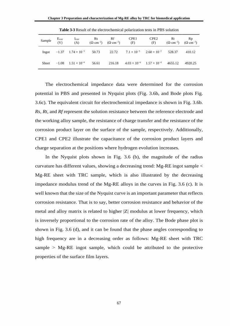
Chapter 3 Preparation and characterization of Mg-RE alloy by TRC for biomedical application
67
Table 3-3 Result of the electrochemical polarization tests in PBS solution
Sample Ecorr (V)
Icorr (A)
Rs (Ω·cm−2)
Rf (Ω·cm−2)
CPE1 (F)
CPE2 (F)
Rt (Ω·cm−2)
Rp (Ω·cm−2)
Ingot −1.37 1.74 × 10⁻³ 50.73 22.72 7.1 × 10⁻⁵ 2.60 × 10⁻² 528.37 410.12
Sheet −1.08 1.51 × 10⁻⁴ 56.61 216.18 4.03 × 10⁻⁶ 1.57 × 10⁻⁴ 4655.12 4920.25
The electrochemical impedance data were determined for the corrosion
potential in PBS and presented in Nyquist plots (Fig. 3.6b, and Bode plots Fig.
3.6c). The equivalent circuit for electrochemical impedance is shown in Fig. 3.6b.
Rs, Rt, and Rf represent the solution resistance between the reference electrode and
the working alloy sample, the resistance of charge transfer and the resistance of the
corrosion product layer on the surface of the sample, respectively. Additionally,
CPE1 and CPE2 illustrate the capacitance of the corrosion product layers and
charge separation at the positions where hydrogen evolution increases.
In the Nyquist plots shown in Fig. 3.6 (b), the magnitude of the radius
curvature has different values, showing a decreasing trend: Mg-RE ingot sample <
Mg-RE sheet with TRC sample, which is also illustrated by the decreasing
impedance modulus trend of the Mg-RE alloys in the curves in Fig. 3.6 (c). It is
well known that the size of the Nyquist curve is an important parameter that reflects
corrosion resistance. That is to say, better corrosion resistance and behavior of the
metal and alloy matrix is related to higher |Z| modulus at lower frequency, which
is inversely proportional to the corrosion rate of the alloy. The Bode phase plot is
shown in Fig. 3.6 (d), and it can be found that the phase angles corresponding to
high frequency are in a decreasing order as follows: Mg-RE sheet with TRC
sample > Mg-RE ingot sample, which could be attributed to the protective
properties of the surface film layers.

Chapter 3 Preparation and characterization of Mg-RE alloy by TRC for biomedical application
68
3.3.3 Immersion test
Fig. 3.7 presents the cross-sectional SEM micrographs of corrosion
morphology of the Mg-RE alloy ingot sample and the sheet with the TRC sample
in PBS solution at 310 K for 10 days. It can be observed from Fig. 3.7 (a) that the
corrosion layer covered the Mg-RE ingot sample surface, which extended to the
inside of the matrix with crack features. In addition, the maximum length of the
corrosion cracks extending to the interior of the matrix was 30 μm, and they were
distributed unevenly along the cross section of the Mg-RE ingot sample. The
improved corrosion-resistance properties of the Mg-RE alloy with TRC are
reflected in Fig. 3.7 (b), in that the corrosion layer is thinner and more uniform.
The results of the energy spectrum analysis indicate that the content of elements in
different location of Mg-RE alloy ingot is dissimilar, which is mainly connected
with the corrosion behavior of the alloy in PBS solution. The mechanism of
corrosion analysis is as described below.
The multiple layers of Mg-RE alloy ingot primarily consisted of C, O, Mg, Al,
Ce and other elements during the immersion test in PBS solution. Mg transformed
into the stable Mg2+ ion in the initial stages. Meanwhile, the cathodic reaction
occurred on account of the galvanic corrosion between the matrix and the
secondary phase, accompanied by the hydrogen evolution [32]. The cathode
reaction formed a heterogeneous thin porous layer which was predominantly
magnesium hydrate on the surface of the Mg-RE alloy. This prevented contact of
the solution and the substrate, resulting in a decrease in the corrosion rate [33].
Moreover, the chloride ions in the PBS solution were able to easily penetrate the
membrane and react with the magnesium hydrate compounds. Therefore,
magnesium hydrate compounds were converted into magnesium chloride
compounds, which are more likely to dissolve into magnesium ions and chloride
ions [34]. The dissolution of the compound leads to a decrease in the magnesium
hydrated compounds around the protective layer, leading to further dissolution of
the matrix.

Chapter 3 Preparation and characterization of Mg-RE alloy by TRC for biomedical application
69
Fig. 3.7 Cross-sectional SEM micrographs of corrosion morphology of (a) the Mg-RE alloy
ingot sample and (b) the sheet with TRC sample in the PBS solution at 310 K for 10 days.
(b)(a)
Fig. 3.8 Metallic ion concentrations of the PBS solution at 310 K with (a) Mg-RE alloy ingot
sample and (b) sheet with TRC sample at day 10, day 20 and day 30 under immersion testing.
Magnesium hydrated films constituted on the surface of magnesium are
generally referred to as crystals. Previous studies have found that the composition
and structure of magnesium and magnesium alloy surface films can be changed
using a rapid solidification process. The conversion of magnesium hydrated films
from a crystal form into an amorphous film structure improves the corrosion
resistance. Amorphous films have better protection than crystalline films, and films
without grain boundaries are better able to resist ion motion than crystalline films
[35]. The Mg-RE alloy sheet obtained by the TRC process has a unique structure

Chapter 3 Preparation and characterization of Mg-RE alloy by TRC for biomedical application
70
due to its crystal structure surrounding the amorphous structure, which may be the
reason for the improvement of the corrosion resistance of the magnesium hydrated
film.
Fig. 3.8 presents the Mg, Al, Ce and La metallic ion concentrations of the
solution for (a) the Mg-RE alloy ingot sample and (b) the sheet with the TRC
sample at day 10, day 20 and day 30 under immersion testing in PBS solution at a
temperature of 310 K. Specifically, both alloys showed a general trend of
increasing Mg ion concentration in the PBS solution with increasing immersion
time from day 10, day 20 and day 30. In contrast, for Al ion concentration, both
alloys showed a decreasing trend. Generally, the Mg-RE alloy ingot sample
showed greater average Mg and Al ion concentration in the PBS solution at each
time point—day 10, day 20 and day 30. From day 10 to day 20 after immersion,
the magnesium ion concentration for the sheet sample was obviously less than the
ingot sample after 10, 20 and 30 days. This may be caused by the rapid corrosion
of alloys in the initial corrosion stage and then the beginning of passivation to slow
down the corrosion. The decrease of aluminum in the corrosive solution may have
resulted from the formation of corrosion products on the surface of the sample.
Fig. 3.8 (a) and 3.8 (b) also shows that throughout the entire 30 day culture
period, the Mg-RE with TRC sample group showed significantly lower release
rates of Ce and La ions than the Mg-RE alloy ingot sample, and the group showed
a general trend of increasing Ce and La ion concentration with increasing
immersion time, but no significant change for the Mg-RE with TRC sample group.
Overall, the content of metallic ions concentrations in the corrosion solution of the
Mg-RE alloy sheet produced by rapid solidification TRC method less than that of
Mg-RE alloy ingot sample within the same amount of immersion time. Which is
probably induced by the special microstructure formed under rapid cooling and
exhibits an improved corrosion resistance.

Chapter 3 Preparation and characterization of Mg-RE alloy by TRC for biomedical application
71
3.3.4 In vivo implantation
The Mg-RE sheet with TRC samples was successfully inserted into the
subcutaneous tissue of the rat thigh and attached to the femur with an AZ31 screw
during surgery, despite the slight mismatches between the Mg-RE sheet and femur
owing to manual surgical placement and the fact that there is only one screw to fix
the femur and alloy sheet. Slight skin swelling was observed in the hind limbs of
the rats during the visual examination of the rats during the study period. The bulge
disappeared after a few days.
Fig. 3.9 reveals the surface volume of the degrading Mg-RE alloy sheet and
bone growth changes, depicted using MicroCT 3D rendering after various
implantation times. As can be seen from Fig. 3.9 (a) and 3.9 (c), two weeks after
surgery, no new bone production was found around the Mg-RE alloy sheet and
femur, and the screw between them was clearly visible. There are no obvious
corrosion pits on the surface of magnesium alloy sheet. Fig. 3.9 (b) and 3.9 (d), six
weeks after the surgery, new bone was formed between the Mg-RE alloy sheet and
the femur. Fig. 3.9 (e) presents on the cross section of the bone–alloy joint, the new
bone is generated and surrounds the original femur. The sheets are attached to the
femur by new bone, which appears to be relatively stable in living organisms. In
the red area shown in Fig. 3.9 (d), corrosion pits began to appear on the surface of
magnesium alloy sheet after six weeks of surgery. This indicates that the films with
improved corrosion resistance of Mg-RE alloy sheet began to degrade in vivo after
6 weeks.

Chapter 3 Preparation and characterization of Mg-RE alloy by TRC for biomedical application
72
Nb
Ob
S
Fig. 3.9 Determination of the volume of the degrading Mg-RE alloy sheet and bone growth
changes, depicted in MicroCT 3D rendering after implantation times of 2 weeks (a,c) and 6
weeks (b,d). A cross section slice of femoral-sheet contact area observed after 6 weeks (e)
shows that the new bone (Nb is represented in green) was formed between the Mg-RE alloy
sheet (S) and the original bone (Ob is represented in blue).
0
20
40
60
80
100
6 weeks
Vol
ume
(mm
3 )
0 weeks
Sheet Volumes
0
100
200
300
400
500
Bone Volumes by region
6 weeks2 weeks0 weeks
Vol
ume
(mm
3 )
Fig. 3.10 Mg-RE sheet degradation after 6 weeks was estimated by the volume of
quantification. This shows a sheet volume loss of 9.32 ± 0.86 mm3 after 6 weeks. MicroCT 3D
rendering after 2 weeks shows there was no obvious change in bone growth around the
degrading Mg-RE sheet. By 6 weeks, as new bone formed between the sheet and the bone, a
notable change in bone volume was observed from 2 to 6 weeks.

Chapter 3 Preparation and characterization of Mg-RE alloy by TRC for biomedical application
73
Mg-RE sheet degradation and femoral change were assessed by volume
quantification in MicroCT 3D rendering separately as shown in Fig. 3.10. Before
surgery, the volume of self-made Mg-RE alloy bone sheet was 94.79 mm3. The
Mg-RE sheet corroded, resulting in 9.32 ± 0.86 mm3 volume loss after 6 weeks.
With regard to the changes in the femur, the volume of the femur did not change
significantly during the two weeks following the surgery. In fact, for some time
after the surgery, the rat lost significantly more weight, the reason for this being
that it took some time for the body to adapt the foreign body. After about five days,
the rats returned to their normal mental state and began to eat normally. By 6 weeks,
as new bone had formed between the sheet and the femur, a noticeable change in
bone volume was observed from 2 to 6 weeks. The rat showed no abnormal
physical or physiological responses during subsequent breeding.
Uniquely, magnesium alloy application has the potential to enhance bone
formation. Several previous studies have shown that the potential performance,
presenting increased bone mass, mineral apposition, and bone mineral density
around magnesium alloy implants in bone [36–39]. In our present study, new bone
appears in the area where the femur contacts the alloy sheet, which confirmed our
findings that the Mg-RE alloy with TRC degradation can lead to the promotion of
bone formation. The new bone formation is not common in absorbable polymers
or permanent metal devices, thus emphasizing the unique advantages of
magnesium fixtures. In this way, the degraded fixture will be gradually replaced in
the future.

Chapter 3 Preparation and characterization of Mg-RE alloy by TRC for biomedical application
74
3.4 Concluding remarks
(1) The Mg-RE alloy sheet was prepared using a vertical-type twin-roll caster
method. Its microscopic characterization experiments show that the crystal
structure is crystalline phase containing amorphous phase.
(2) EPMA experiments show that Al, La and Ce elements are enriched in the
amorphous phase region and the grain boundary region. However, Mg is evenly
distributed throughout the microscopic region. This shows that segregation is more
likely to affect Al, La and Ce elements.
(3) Electrochemical tests and immersion test results revealed that Mg-RE
sheet with TRC has a better corrosion resistance than master alloy, and a uniform
corrosion layer on the surface.
(4) In vivo, as an implant material, the tests show that Mg-RE alloys sheets
were safe with respect to rat physical fitness and induced new bone formation; thus,
they were promising for utilization as implant materials in the future.

Chapter 3 Preparation and characterization of Mg-RE alloy by TRC for biomedical application
75
3.5 References
1. Green, A.L.; Ma, E. Bulk Metallic Glasses: At the Cutting Edge of Metals Research.
MRS Bulletin 2007, 32, 611–619.
2. Chen, Q.Z.; Thouas, G.A. Metallic implant biomaterials. Mater. Sci. R 2015, 87, 1–57.
3. Wise, D.L.; Trantolo, D.J.; Altobelli, D.E.; Yaszemsk, M.J.; Grasser, J.D. Human
Biomaterials Application; Humana Press: Totowa, NJ, USA, 1996.
4. Yaszemsk, M.J.; Trantolo, D.J.; Lewandrowski, K.U.; Hasirci, V.; Altobelli, D.E.;
Wise, D.L. Biomaterials in Orthopedics; Marcel Dekker Inc.: New York, NY, USA,
2004.
5. Matusiewicz, H. Potential release of in vivo trace metals from metallic medical
implants in the human body: From ions to nanoparticles—a systematic analytical
review. Acta Biomater. 2014, 10, 2379–2403.
6. Heary, R.F.; Parvathreddy, N.; Sampath, S.; Agarwal, N. Elastic modulus in the se-
lection of interbody implants, J. Spine Surg. 2017, 3, 163–167.
7. Andreas, A.K.; Jörg, F.L.; Florian, H.D.T. Rapid Solidification and Bulk Metallic
Glasses—Processing and Properties. In Materials Processing Handbook; CRC Press:
Boca Raton, FL, USA, 2007; PP. 17-1-17-44.
8. Masumoto, T.; Maddin, R. The mechanical properties of palladium 20 a/o silicon alloy
quenched from the liquid state. Acta Metall. 1971, 19, 725–741.
9. Liebermann, H.; Graham, C. Production of amorphous alloy ribbons and effects of
apparatus parameters on ribbon dimensions. IEEE Trans. Magn. 1976, 12, 921–923.
10. Narasimhan, M.C. Continuous casting method for metallic strips. U.S. Patent
4,142,571. 22 October 1979.
11. A. Inoue, T. Nakamura, T. Sugita, T. Zhang, T. Masumoto. Bulky La-Al-TM
(TM=Transition Metal) Amorphous Alloys with High Tensile Strength Produced by a
High-Pressure Die Casting Method. Mater. Trans. JIM 1993, 34, 351–358.
12. Barekar, N.S.; Dhindaw, B.K. Twin-roll casting of Aluminum alloys—An overview.
Mater. Manuf. Process. 2014, 29, 651–661.
13. Chen, H.S.; Miller, C.E. A Rapid Quenching Technique for the Preparation of Thin
Uniform Films of Amorphous Solids. Rev. Sci. Instrum. 1970, 41, 1237–1238.
14. East, D.R.; Kellam, M.; Gibson, M.A.; Seeber, A.; Liang, D.; Nie, J.F. Amorphous
magnesium sheet produced by twin roll casting. Mater. Sci. Forum 2010, 654, 1078–
1081.

Chapter 3 Preparation and characterization of Mg-RE alloy by TRC for biomedical application
76
15. Lee, J.G.; Park, S.S.; Lee, S.B.; Chung, H.T.; Kim, N.J. Sheet fabrication of bulk
amorphous alloys by twin-roll strip casting. Scr. Mater. 2005, 53, 693–697.
16. Oh, Y.S.; Lee, H.; Lee, J.G.; Kim, N.J. Twin-Roll Strip Casting of Iron-Base
Amorphous Alloys. Mater. Trans. 2007, 48, 1584–1588.
17. Urata, A.; Nishiyama, N.; Amiya, K.; Inoue, A. Continuous casting of thick Fe-base
glassy plates by twin-roller melt-spinning. Mater. Sci. Eng. A 2007, 449, 269–272.
18. Suzuki, T.; Anthony, A.M. Rapid quenching on the binary systems of high temperature
oxides. Mater. Res. Bull. 1974, 9, 745–753.
19. Lee, J.G.; Lee, H.; Oh, Y.S.; Lee, S.; Kim, N.J. Continuous fabrication of bulk
amorphous alloy sheets by twin-roll strip casting. Intermetallics 2006, 14, 987–993.
20. Hofmann, D.C.; Roberts, S.N.; Johnson, W.L. Twin Roll Sheet Casting of Bulk Metallic
Glasses and Composites in an Inert Environment. U.S. Patent 20130025746 A1, 31
January 2013.
21. Ding, P.-D.; Pan, F.-S.; Jiang, B.; Wang, J.; Li, H.-L.; Wu, J.-C.; Xu, Y.-W.; Wen, Y.
Twin-roll strip casting of magnesium alloys in China. Transactions of Nonferrous
Metals Society of China, 2008, 18, s7−s11.
22. Hu, X.; Ju, D.; Zhao, H. Thermal flow simulation of twin-roll casting magnesium alloy.
J. Shanghai Jiaotong Univ. 2012, 17, 479−483.
23. Luo, L.T.; Gong, X.B.; Li, J.Z.; Kang, S.B.; Cho, J.H. Microstructure and Mechanical
Properties of Severely Deformed Mg-4.5Al-1.0Zn Alloy Processed by Asymmetric
Rolling on Ingot and Twin Roll Cast Strip. Mater. Res. 2016, 19, 207–214.
24. Park, S.S.; Park, W.J.; Kim, C.H.; You, B.S.; Kim, N.J. The Twin-Roll Casting of
Magnesium Alloys. JOM 2009, 61, 14–18.
25. Pei, Z.P.; Ju, D.Y.; Li, X. Simulation of critical cooling rate and process conditions for
metallic glasses in vertical type twin-roll casting. Trans. Nonferrous Met. Soc. China
2017, 27, 2406−2414.
26. Holzwarth, U.; Gibson, N. The Scherrer equation versus the ‘Debye-Scherrer equation’.
Nat. Nanotechnol. 2011, 6, 534.
27. Pecharsky, V.K.; Zavalij, P.Y. Properties, Sources, and Detection of Radiation.
Fundamentals of Powder Diffraction and Structural Characterization of Materials;
Springer: Boston, MA, USA. 2009; pp. 107–132.
28. In-Ho Jung, Mehdi Sanjari, Junghwan Kim, Stephen Yue. Role of RE in the
deformation and recrystallization of Mg alloy and a new alloy design concept for Mg–
RE alloys. Scr. Mater. 2015, 102, 1–6.

Chapter 3 Preparation and characterization of Mg-RE alloy by TRC for biomedical application
77
29. Takeuchi, A.; Inoue, A. Calculations of mixing enthalpy and mismatch entropy for
ternary amorphous alloy. Mater. Trans. JIM 2000, 41, 1372–1378.
30. Inoue, A. Stabilization of metallic supercooled liquid and bulk amorphous alloys. Acta
Mater. 2000, 48, 279–306.
31. Anawati, A.; Asoh, H.; Ono, S. Effects of alloying element Ca on the corrosion
behavior and bioactivity of anodic films formed on AM60 Mg alloys. Materials 2017,
10, 11.
32. Song, Y.; Han, E.; Shan, D.; Yim, C.D.; You, B.S. Corros. Sci. 2012, 60, 238–245.
33. Zhang, B.; Hou, Y.; Wang, X.; Wang, Y.; Geng, L. Mater. Sci. Eng. C 2011, 31, 1667–
1673.
34. Bakhsheshi-Rad, R.; Abdul-Kadir, M.R.; Idris, M.H.; Farahany, S. Corros. Sci. 2012,
64, 184–197.
35. Makar, G.L.; Kruger, J. Corrosion of magnesium. Intern. Mater. Rev. 1993, 38, 138–
153.
36. Witte, F.; Kaese, V.; Haferkamp, H.; Switzer, E.; Meyer-Lindenberg, A.; C.J. Wirth;
H. Windhagen. In vivo corrosion of four magnesium alloys and the associated bone
response. Biomaterials 2005, 26, 3557–3563.
37. Janning, C.; Willbold, E.; Vogt, C.; Nellesen, J.; Meyer-Lindenberg, A.; Windhagen,
H.; Windhagen, F. Thorey, F. Witte. Magnesium hydroxide temporarily enhancing
osteoblast activity and decreasing the osteoclast number in peri-implant bone
remodelling. Acta Biomater. 2010, 6, 1861–1868.
38. Yang, J.X.; Cui, F.Z.; Lee, I.S.; Zhang, Y.; Yin, Q.S.; Xia, H.; SX Yang. In vivo
biocompatibility and degradation behavior of Mg alloy coated by calcium phosphate
in a rabbit model. J. Biomater. Appl. 2012, 27, 153–164.
39. Yoshizawa, S.; Brown, A.; Barchowsky, A.; Sfeir, C. Magnesium ion stimulation of
bone marrow stromal cells enhances osteogenic activity, simulating the effect of
magnesium alloy degradation. Acta Biomater. 2014, 10, 2834–2842.

Chapter 4 In vivo degradation behaviour and bone response of cast-rolled alloy in rat femoral model
78
Chapter 4 In vivo degradation behaviour and bone
response of cast-rolled alloy in rat femoral model
A new type of Mg-rare earth (Ce, La) and AZ31 alloy sheets were prepared
by vertical twin-roll casting (TRC) technology under identical casting conditions,
and their microstructure features, degradation behavior and bone response were
investigated. Microstructure characterization showed that the Mg-RE exhibited a
higher amorphous forming ability than the AZ31. The Ti, Mg-RE and AZ31 sheet
implants were implanted in immobilized rat femur model to observe degradation
behavior during 16 weeks. The results showed that no significant change was found
in the femur surrounding the Ti. This excluded the external factor that the new bone
formation resulting from bone remodeling. The degradation rate of the Mg-RE was
about 0.11 mm/year after 16 weeks implantation, significantly slower than that of
AZ31. In addition, the Mg-RE induced more newly formed bone, which met the
necessary conditions for the prevention of pathological fractures. Therefore, the
novel Mg-RE alloy appear to hold a healing candidate as the biodegradable implant
material.
4.1 Introduction
Magnesium (Mg) alloys with excellent biocompatibility, biodegradability,
and bone formation capacity have been widely applied to manufacture bone
fixation implants. It is reported that Mg alloys can reduce the risk of the load-
shielding after implanting surgery due to their Young’s modulus similar to bone
[1]. Furthermore, studies have shown that Mg-based alloys implanted within or
surrounding the bone present very good biocompatibility [2-6]. Unlike resorbable
polymers and permanent inert materials such as stainless steel and titanium (Ti)
alloys, Mg alloys possess a unique degradation which is being explored for various
orthopedic applications. Hence, there is no necessary to perform a second removal

Chapter 4 In vivo degradation behaviour and bone response of cast-rolled alloy in rat femoral model
79
surgery of the implant after osseous union. It is noteworthy that most of studies of
Mg alloys implants are in animals, for instance, rabbit [7], rat [8], pig [9] which
present good biocompatibility and normal physiological for different types of Mg
alloys. It is demonstrated that Mg2+ ions released from Mg-based alloys could
present bioeffect for instance inducing new partial bone formation [10-13].
Moreover, the bone around Mg alloy implants presented increased bone mass,
mineral apposition and bone mineral density [14-17]. However, Mg-based alloys
have its limitations, such as a notably rapid degradation rate reported by previous
research [18]. The rapid degradation results in producing Mg hydroxide and
hydrogen gas leading to a change in the PH of the tissue fluid which is the most
likely to cause tissue inflammation and adversely affect the viability of cells.
Therefore, there is a growing need of developing novel degradable magnesium
alloys with superior corrosion resistance performances.
It is well known that some rare-earth elements have been found in the human
body [19], and the addition of rare-earth elements could effectively improve the
corrosion resistance and mechanical properties of Mg alloys [20,21]. Due to the
presence of sensitive impurities, the corrosion resistance of Mg alloys will be
damaged once the contents of impurities exceed the tolerance limits [22]. However,
the rare-earth elements in Mg alloy could combine with the impurities (Cu, Fe, Ni,
etc.) forming depositions during the melting process. This effect is so-called “the
scavenger effect”. It is believed that the scavenger of rare-earth can effectively
improve the corrosion resistance of Mg alloys. In addition, rare-earth elements such
as Ce and La could optimize the microstructure of Mg alloys and improve the
corrosion resistance of Mg alloys [23]. Hence, researching new type of Mg-RE (RE
= rare-earth) alloy is a direction to reduce degradation rate.
On the other hand, optimizing the microstructure of materials is another
approach to improve corrosion resistance. It is well known that metallic glasses
(MGs), as a newcomer in the field of metals (liquid metals or amorphous/glassy
alloys), have an amorphous structure endows unique properties such as lower
Young’s modulus, higher strength, excellent corrosion resistant and fatigue [24,25].

Chapter 4 In vivo degradation behaviour and bone response of cast-rolled alloy in rat femoral model
80
Previous studies have shown that twin roll casting (TRC) is a useful technique for
preparing amorphous alloy sheets with a wide range of cooling rates. Therefore,
TRC process has a great significance to develop new corrosion resistant Mg alloys
with amorphous phase.
In the present study, a new Mg alloy was developed by adding rare earth (La,
Ce) and adopter for vertical-type twin roll casting. Details of microstructure, in
vivo degradation (In this study, “degradation” has the same meaning with
“corrosion”) and bone response of a new Mg-RE (Ce, La) and AZ31 implants were
investigated during a 16-week observation by a fixed model in rat femoral. In
addition, the evaluation of bone response might be influenced by bone remodeling
result from fixed model. Therefore, we compared the bone response of non-
absorbent Ti with those of casting-rolled Mg-RE and AZ31 to excluded the external
factor caused by altering the mechanical loading of the implants.
4.2 Materials and Methods
4.2.1 Material preparation and characterization
High purity of Mg ingot (99.99%), AZ31 ingot, Mg-10La and Mg-20Ce (in
wt.%) were used as raw materials. The melting process was carried out in a
resistance furnace under the protection of a mixture of CO2 and FS6. AZ31 sheets
in this study were produced by melting Mg ingot and AZ31 ingot. The Mg-RE
sheets in this study were produced by melting Mg ingot, AZ31 ingot, Mg-10La and
Mg-20Ce. Firstly, the Mg ingot and AZ31 ingot were placed into the resistance
furnace, and the compound were heated up to 720 ℃ for 1.5 h to completely melted.
Secondly, the Mg-10La and Mg-20Ce master alloys were added into the melt, then
the melt temperature reduced to 700 ℃ and held for 1.5 h. It can be seen that AZ31
alloy sheets could be obtained in the first casting process, while Mg-RE alloy sheets
could be obtained in the whole casting process. The chemical compositions of the
alloy sheets were determined by X-ray fluorescence spectrometry and the results

Chapter 4 In vivo degradation behaviour and bone response of cast-rolled alloy in rat femoral model
81
were listed in Table 4-1.
Table 4-1 chemical composition of the cast-rolled sheets
Cast-rolled
sheets
Thickness
(mm)
Width
(mm)
Element (wt.%)
Al Si Mn Zn La Ce Mg
AZ31 1.1 75 2.55 0.22 0.43 0.75 - - Bal.
Mg-RE 1.2 80 1.21 0.16 0.27 0.21 1.53 2.78 Bal.
The TRC experiments were carried out on a vertical-type twin roll casting mill
with two identical rolls made of copper alloy. The diameter and width of both rolls
are 300 mm and 100 mm respectively, and the initial roll gap was set to be 0 mm.
In consideration of the separation force generated in the casting process, metal
blocks were set at the two rotating rolls side to form a supporting force, minimizing
the roll gap during casting process as much as possible. When the alloy melted
completely, the melt was introduced into the roll gap between the left and right
rolls through the asbestos casting nozzle, and the casting rolls begins to operate
with 30 rpm. An oil tank was placed under the rotating rolls to avoid further grain
growth, hence the cast sheet dipped into the tank could quickly solidify as exits at
the rolls. The schematic diagram and practicality illustration of TRC are shown in
Fig. 2.5 (a) and Fig. 2.5 (b), respectively.
The specimens with the size of 10 mm in width and 10 mm in length were cut
from the sheets, and the transversal cross-section was selected for microstructure
analysis. The microstructures were observed using a field emission scanning
electron microscope (FE-SEM, JMS-6301, Japan), In addition, the elements
distribution maps were performed by electron probe micro-analysis (EPMA, JXA-
8530F, Japan). The secondary dendrite arm spacing of AZ31 and Mg-RE were
analyzed by Image-Pro analysis software. At least 6 metallographic images were
selected for each alloy sheet, and more than 60 groups of secondary dendrites
randomly distributed were counted for each metallographic image, and the average

Chapter 4 In vivo degradation behaviour and bone response of cast-rolled alloy in rat femoral model
82
value was taken as the final secondary dendrite arm distance. The focused ion beam
(FIB, JIB-4500, Japan) and the transmission electron microscopy (TEM, HF-3300,
Japan) were used to identify the crystal structure of the samples.
4.2.2 Implant method
The Ti, Mg-RE and AZ31 samples were lathe machined into 15 mm × 5 mm
with a thickness 0.5 mm. All surfaces were grounded with SiC papers up to 1200
grid in order to ensure surface flatness and roughness. Ti and Mg screws (4.5 mm
in length, with a shaft diameter of 3.2 mm) were selected to immobilized the Ti,
and casting-rolled sheets respectively.
4.2.3 Electrochemical characterization
In vitro corrosion tests were conducted at the temperature of 310 K in 3.5%
NaCl solution. EIS (Modulab XM, Tokyo, Japan) and Potentiodynamic
polarization (HZ700, Tokyo, Japan) tests were performed in a three-electrode cell.
Sheet samples were connected as the working electrodes. Potentials were measured
versus the Ag/AgCl electrode. Platinum played the role of auxiliary electrode. The
samples were immersed in the 3.5% NaCl solution for one-hour at their open circuit
potential. The EIS tests were recorded in a frequency range from 10-2 Hz to 105 Hz
applying a sinusoidal AC voltage signal of 0.01 V amplitude. Potentiodynamic
polarization were initiated at a 0.01 V/s scan rate from the open circuit potential
(Eoc) to Vvs Ag/AgCl, and then from Vvs Ag/AgCl to Eoc.
4.2.4 Micro-CT analysis
Micro-CT was used to evaluate implants degradation and the formation of
new bone. Image processing was performed by means of 3D Viewer and Volume
Rendering Control. 3D volumes of the scanned devices were generated from
acquired 2D lateral projections using a Simple Viewer software.

Chapter 4 In vivo degradation behaviour and bone response of cast-rolled alloy in rat femoral model
83
4.2.5 In vivo corrosion assessment
The transversal cross-section morphology and elemental composition of Mg-
RE and AZ31 sheets were observed by a field emission scanning electron
microscope (FE-SEM, JMS-6301, Japan) and the elements distribution maps were
observed by electron probe micro-analysis (EPMA, JXA-8530F, Japan). The
procedure of removal of sheets from femur without damaging the tissue formed
between the sheet and femur.
4.2.6 Histological observation
The femur samples surgically extracted from the rats were fixed in 10%
formalin solution for 48 hours and decalcified with a decalcification solution (10%
ethylenediamine tetra-acetic) for 28 days. Next, the samples were rinsed by running
water and dehydrated in a graded series of alcohol solution (70%, 80%, 95% and
99% alcohol, 2 h each). Then the dehydrated samples were imbedded in a paraffin
block. A cutting-grinding unit was used to slice the section of the femurs in contact
with the sheets. Finally, the slice samples were stained by hematoxylin and eosin
(H&E) and then the new bone morphology were observed by a microscope.
4.2.7 Statistical analysis
All experimental data analysis was conducted using SPSS 20. Statistical
significance was analyzed using one-way analysis of variance (ANOVA) followed
by Tukey tests. The statistical significance was set a p-value of less than 0.05
(p<0.05).

Chapter 4 In vivo degradation behaviour and bone response of cast-rolled alloy in rat femoral model
84
4.3 Results and discussion
4.3.1 Microstructures analysis
Fig. 4.1 shows the microstructure of AZ31 and Mg-RE sheets produced by
TRC process. It can be seen from Fig. 4.1 (a) that the microstructures of the casting-
rolled AZ31 are composed of unevenly distributed dendrite regions. The fine
dendrites are obvious in the yellow rectangle region as shown in Fig. 4.1 (b) which
are named AZ31’s region of interest (A-ROI). Fig. 4.1 (c) displays the
microstructures of Mg-RE sheets which are mainly characterized by dendrites with
closely spaced secondary dendrite arms and fine equiaxed crystals. Meanwhile, it
can be found that some special regions having no visible crystalline features
indicated by the yellow rectangle region as shown in Fig. 4.1 (d), which are named
Mg-RE’s region of interest (M-ROI).
To determine the phase of A-ROI and M-ROI, high resolution transmission
electron microscope (HR-TEM) images with selected area electron diffraction
(SAED) patterns of those two observation regions are shown in Fig. 4.2. It can be
observed that the atoms are arranged in regular lines in A-ROI, and the SAED
pattern indicates A-ROI is the hexagonal close packed lattice (HCP) structure, as
shown in Fig. 4.2 (a). However, HR-TEM image of M-ROI shows that there are
three types atomic arrangements displayed in Fig. 4.2 (b).

Chapter 4 In vivo degradation behaviour and bone response of cast-rolled alloy in rat femoral model
85
Fig. 4.1 Cross-section microscopic morphologies of casting-rolled AZ31 sheet (a, b) and Mg-
RE sheets (c, d).
Fig. 4.2 HR-TEM images and corresponding SAED patterns showing A-ROI in AZ31 sheets
(a) and M-ROI in Mg-RE sheets, respectively.

Chapter 4 In vivo degradation behaviour and bone response of cast-rolled alloy in rat femoral model
86
The atoms arranged in order is determined to be HCP structure, while the
atoms arranged in disorder is confirmed to be amorphous phase. The interface
between crystal phase and amorphous phase exhibits HCP diffraction pattern.
Those results indicate that Mg-RE alloy contains amorphous structure.
Fig. 4.3 (a) and (b) shows the statistical results of secondary dendrites arm
spacing of the AZ31 and Mg-RE sheets. The average secondary dendrite arm
spacing of the AZ31 and Mg-RE is 0.75 μm and 0.62 μm, respectively. Secondary
dendrite arm spacing is correlated with the solidification rate, and increase cooling
rate can result in finer secondary dendrite arm spacings [27]. According to the
previous research [28], the quantitative between the cooling rate and secondary
dendrite arm spacings following relationship:
λ=35.5R-0.31 (4.1)
where R is averaged cooling rate (K·s-1) during solidification; λ is the distance
between secondary dendrites (μm). Based on formula (1), the AZ31 and Mg-RE
were obtained under casting condition with cooling rate of 2.53 × 10⁵ K·s-1 and
4.68 × 10⁵ K·s-1, respectively, which both presented a fast cooling rate. The
research [29] present that the formula (4.1) is applicable for the cooling rate of 10-
1 K·s-1 ~ 106 K·s-1. According to the calculation results, it is suitable to use the
formula (4.1) to evaluate the cooling rate during TRC process. The SEM image of
the Mg-RE containing amorphous regions is presented in Fig. 4.3 (c), and the
volume fraction containing amorphous of M-ROI statistical results is given in Fig.
4.3 (d). It can be seen that the average volume fraction of the regions containing
amorphous is 14.3% in the Mg-RE sheet samples. From the above results, it can be
concluded that the Mg-RE can possess an amorphous phase made by TRC method.
However, it is quite hard to obtain amorphous phase for the AZ31, even trying to
build a fast cooling rate with TRC method. Therefore, the amorphous phase
forming ability of the Mg-RE is higher than the AZ31 during rapid cooling
solidification. Hence, it is hypothesized that the Mg-RE alloy has a better corrosion
resistant than AZ31 alloy.

Chapter 4 In vivo degradation behaviour and bone response of cast-rolled alloy in rat femoral model
87
0.2 0.3 0.4 0.5 0.6 0.7 0.8 0.9 1.0 1.1 1.2 1.3 1.40
5
10
15
20
25
30
Freq
uenc
y (%
)
Secondary dendrite arm spacing arm (μm)
Average spacing 0.75 μ m
(a)
0.2 0.3 0.4 0.5 0.6 0.7 0.8 0.9 1.0 1.1 1.2 1.3 1.40
5
10
15
20
25
30(b)
Average spacing 0.62 μ m
Freq
uenc
y (%
)
Secondary dendrite arm spacing arm (μm)

Chapter 4 In vivo degradation behaviour and bone response of cast-rolled alloy in rat femoral model
88
0 3 6 9 12 15 18 21 24 27 30 33 360
5
10
15
20
25(d)
Average volume fraction 14.3 %
Freq
uenc
y (%
)
Volume fraction of M-ROI (%)
Fig. 4.3 Statistical results of secondary dendrites arm spacing of AZ31 sheets (a) and Mg-RE
sheets (b); SEM micrograph of Mg-RE (c), volume fraction estimation of M-ROI, indicated by
the yellow regions and the statistical results is shown in (d).

Chapter 4 In vivo degradation behaviour and bone response of cast-rolled alloy in rat femoral model
89
Fig. 4.4 The Mg, Ce and La element distribution of the Mg-RE sheet in region
containing amorphous phase regions.
Fig. 4.4 shows the Mg, Ce and La elements distribution of the Mg-RE sheet
containing amorphous phase regions. It can be seen that Mg is evenly distributed
on the substrate, Ce and La concentrated in the region containing the amorphous,
which indicates that addition Ce and La into the Mg-based alloy is beneficial to
form amorphous. As the secondary dendrite arm spacing around the amorphous
phase is very short, it can be seen from formula (4.1) that this region has a large
cooling rate during solidification. If the cooling rate is large enough, the atoms with
a high melting point in the melt loose kinetic energy when the temperature drops
[30]. For these reasons, the atoms in the melt to freeze and form an amorphous
phase.

Chapter 4 In vivo degradation behaviour and bone response of cast-rolled alloy in rat femoral model
90
In general, the key factor of preparing amorphous alloys is to obtain high
cooling rates during solidification of casting alloys. In this study, the current TRC
conditions could provide a rapid cooling rate up to 105 K·s-1. If the cooling rate is
fast enough that crystal structure in the melting liquid has no time to nucleate and
grow, the liquid can avoid crystallization during rapid solidification. The liquid is
called supercooled liquid. The viscosity of supercooled liquid can be expressed by
the following equation [31]:
η-1 = Aexp(-K/Vf) (4.2)
where A and K are constant; Vf is free volume. In this study, there were more
element components in Mg-RE relative to AZ31, and larger atomic size difference
among the major elements. For example, the relative atomic radius difference
between Mg and rare-earth elements (Ce, La) is more than 12%. According to
formula (4.2), the larger atomic size difference will result in reducing free volume
and increasing the viscosity of the supercooled liquid. Increasing the viscosity of
the supercooled liquid makes the atoms hard to spread over long-range, so it is
easier for the alloys to form amorphous states. In addition, an appropriate negative
enthalpy of mixing (∆Hmix [AB]) between major elements is also a necessary
condition for good amorphous forming ability [32]. The ∆Hmix [AB] of Mg-Ce
and Mg-La calculated by Miedma’s model are both −7 KJ/mol [33]. In general, the
Mg-RE are easier to form amorphous phase than the AZ31.
The solute distribution coefficient during the rapid solidification process can
be expressed as [34]:
K=Cs/CL (3)
Where K is the solute partition coefficient; Cs is the solute concentration in the
liquid phases; CL is solute concentration in the solid phases. The K values of the
major elements such as Ce and La in Mg-RE is less than 1 during solidification.
Based on formula (3), the content of solute elements (Ce, La) in preferentially
crystallized solids is less than the content of solute elements (Ce, La) in
surrounding liquids. Solute atoms such as Ce and La are continuously discharged

Chapter 4 In vivo degradation behaviour and bone response of cast-rolled alloy in rat femoral model
91
into the liquid phase and enriched the supercooled liquid regions during rapid
solidification process (Fig. 4.4).
4.3.2 In vitro corrosion properties
To get information about the corrosion behavior of those sheets, the corrosion
resistance of the three samples was evaluated by EIS and potentiodynamic
polarization in 3.5% NaCl solution at temperature of 310 K after one-hour
immersion, as shown in Fig. 4.5. The Nyquist and Bode plots (Fig. 4.5 a-c) of the
AZ31, Mg-RE and Ti were characterized by two apparent time constants in the two
capacitive loops of high-middle and low frequency areas. The equivalent circuit
(Fig. 4.5 a) was used to investigate the EIS quantitatively, and the fitting results
presents in Table 2. The equivalent circuit model consisted of Rs (solution
resistance), R1 (charge-transfer resistance), R2 (film resistance), constant elements
CPE1 and CPE2, where, CPE1 and CPE2 represent the capacitive behaviors of
oxidation film and charge-transfer, and Q is the CPE magnitude, n value is a nature
element [35]. Generally, an increase in the values of the charge transfer resistance
with a decrease in the dissolution rate of the materials substrate [36]. According to
the results of Table 4-2, both R1 and R2 of the AZ31 are lowest among those sheets,
indicating an increased dissolution rate of the materials substrate. The sum of R1
and R2 for sheets were in the following order: AZ31 < Mg-RE < Ti, indicating the
Mg-RE possess a better corrosion resistance than AZ31.

Chapter 4 In vivo degradation behaviour and bone response of cast-rolled alloy in rat femoral model
92
(d)(c)
(b)(a)
Fig. 4.5 (a) Electrochemical behaviors of the AZ31, Mg-RE and Ti implants in 3.5% NaCl
solution: (a) Nyquist spectra plots and equivalent circuit; (b, c) Bode plots of EIS; (d) The
potentiodynamic polarization curves.
The potentiodynamic polarization curves of the sheet materials in 3.5% NaCl
solution at temperature of 310 K after one-hour immersion are shown in Fig. 4.5
(d). The average values corrosion potential (Ecorr) and corrosion current density
(icorr) measured by Tafel extrapolation are presented in Table 4-3. The Mg-RE have
more positive value of Ecorr (-0.88 V vs Ag/AgCl) and lower icorr (5.1×10⁻⁴ A cm-2)
than these of AZ31, which implies the rolled samples of the Mg-RE present a
higher corrosion resistance. In conclusion, the results of the electrochemical tests
confirm the hypothesis that the Mg-RE alloys with higher amorphous forming
ability have better corrosion resistance. In this study, the Mg-RE has an amorphous
structure, in which the atoms have short-range arranging or are no crystalline
defects, like gain boundaries or dislocations. A previous study [37] showed that

Chapter 4 In vivo degradation behaviour and bone response of cast-rolled alloy in rat femoral model
93
amorphous alloys have much higher corrosion resistance than crystalline alloys due
to the absence of grain boundaries and second phases.
Table 4-2 Fitting resulting of EIS spectra
Alloy RS
(Ω cm2) CPE1 R1
(Ω cm2) CPE2 R2
(Ω cm2) Q1 (μF cm-2sn) n Q2 (μF cm-2sn) n AZ31 24.89 274.8 0.84 24.45 5496 0.82 279.7
Mg-RE 25.11 66.83 0.81 31.7 3864 0.83 528.4
Ti 24.96 5350 0.80 90.09 10670 0.81 1328
Table 4-3 Ecorr and Icorr values for AZ31, Mg-RE and Ti in 3.5% NaCl solution
Sample Ecorr (V vs Ag/AgCl) Icorr (A cm-2)
AZ31 -1.13 9.5×10⁻³
Mg-RE -0.88 5.1×10⁻⁴
Ti -0.25 1.2×10⁻⁵
4.3.3 Animal test
All fixed implants were well accommodated by the animals and without any
obvious adverse health events and the animals showed no gas cavities in vivo.
During 16-week observation period after the operation, experimental animals
resumed normal movement and behavior bearing on both forearms (Date not
shown).
4.3.4 Degradable implant cross-sectional examination
For studying the corrosion products of the Mg-RE and AZ31 implants that in
vivo contact with the femur, Mg and other elements such as C, O, P and Ca in
corrosion layer were studied. The morphologies of the cross-section of the Mg-RE
and AZ31 and corresponding elements distribution were detected by the EPMA
mapping surface-scan at 8 and 16 weeks postoperatively as shown in Fig. 4.6 and
Fig. 4.7. Mg, O, C, P, Ca and rare-earth (Ce, La) distributions in the cross-section

Chapter 4 In vivo degradation behaviour and bone response of cast-rolled alloy in rat femoral model
94
of the sheets were analyzed. After the Mg-RE and AZ31 were implanted with
femur for 8 weeks (Fig. 4.6), the external surface of the implants began to degrade.
The Mg substrate was transformed into magnesium hydroxide and the compound
containing O, C, P and Ca as the corrosion products. It also can be seen that the
amount of Mg in corrosion layer of Mg-RE was higher than that AZ31. This
demonstrated that the in vivo corrosion products of the Mg-RE have thicker
protective magnesium hydroxide layer than the AZ31. Furthermore, the rare earth
(La, Ce) distribute in the corrosion layer and the substrate of Mg-RE were rather
homogeneous.
As the implantation time for 16 weeks (Fig. 4.7), O, C, P and Ca distributions
extended to the internal section gradually. The Mg in corrosion layer of the Mg-
RE was slight decreased from 8 weeks after implantation. However, the Mg content
in the AZ31 corrosion layer was very low, which suggested the magnesium
hydroxide almost degraded. In addition, the rare earth (Ce, La) in the corrosion
layer have not changed significantly. The experimental results demonstrate that the
degradation of the Mg-RE was more slowly than that of the AZ31, which may be
ascribed to the addition rare-earth (Ce, La) relieved the degradation of the
magnesium hydroxide, thus improving the corrosion resistance.

Chapter 4 In vivo degradation behaviour and bone response of cast-rolled alloy in rat femoral model
95
(a)
(b)
Fig. 4.6 Cross-section images and EPMA surface-scan of (a) Mg-RE sheets, and (b) AZ31
sheets after 8 weeks implantation.

Chapter 4 In vivo degradation behaviour and bone response of cast-rolled alloy in rat femoral model
96
(a)
(b)
Fig. 4.7 Cross-section images and EPMA surface-scan of (a) Mg-RE sheets, and (b) AZ31
sheets after 16 weeks implantation.

Chapter 4 In vivo degradation behaviour and bone response of cast-rolled alloy in rat femoral model
97
In general, the poor corrosion resistance of Mg-based alloys limits their
application as implants. The reasons for rapid degradation of Mg-based alloys is
multifaceted, but mainly due to the chloride ion transform magnesium hydroxide
protection layer into soluble magnesium chloride [38]. In this study, the total
amount of Mg in corrosion layer of the AZ31 significant decreased after 8 weeks
and 16 weeks implantation compared with the Mg-RE (Fig. 4.6 and 4.7).
Consequently, the corrosion resistance of the AZ31 decreased with the amount of
Mg element compared with the Mg-RE. It is noting that the rare-earth (Ce, La) in
the corrosion layer of the Mg-RE were homogeneous distribution after 8weeks and
16 weeks implantation respectively (Fig. 4.6 and 4.7). Because of enrichment of
rare-earth (Ce, La) in the corrosion layer of magnesium alloys, the corrosion
product layer was complete and compact, which improved the protective
effectiveness of the corrosion layer and restrains further degradation of Mg
substrate in corrosive mediums [39].
The degradation products mainly contain Mg, O, C, P and Ca, which exist
both in the Mg-RE and AZ31. Previous studies [40-42] have demonstrated that
these degradation products similar to composition of nature bone exhibit good
biocompatibility. Therefore, it can draw the conclusion that the biocompatibility of
the degradation products of the Mg-RE is acceptable as biomaterials.
4.3.5 Bone response and histological examination
Fig. 4.8 shows the representative images of 3D micro-CT reconstruction of a
rat femur with implanted sheets 2 weeks, 8 weeks and 16 weeks after surgery. The
Ti, Mg-RE and AZ31 implants remained in their original position, and bone callus
formation was observed in the 500-slice region of interest. In the Ti group, there
was no bone callus formation at the area between the Ti sheet and the femur in all
experimental periods. Limited bone callus formation could be detected between the
AZ31 sheet and the femur at 8 and 16 weeks of implantation. In contrast, a large
increase in bone mass was found at the area between the Mg-RE sheet and the

Chapter 4 In vivo degradation behaviour and bone response of cast-rolled alloy in rat femoral model
98
femur. The boundary between the Mg-RE sheet and the femur was not obvious
after 16 weeks implantation resulting from the new bone formation.
Fig. 4.8 Representative 3D micro-CT reconstruction illustrating the bone respond of Ti, Mg-
RE and AZ31 sheet implants after 2, 8 and 16 weeks postoperatively. Yellow boxes indicate
the horizontal section region of interest BV/TV: bone volume/tissue volume. Tb. N: umber of
trabecular bone.

Chapter 4 In vivo degradation behaviour and bone response of cast-rolled alloy in rat femoral model
99
Fig. 4.9 Decalcified sections with hematoxylin and eosin (H&E) staining showing the
morphology of the peri-existing bone and the new bone around the implants (black boxes) 16
weeks after implantation.
Fig. 4.10 Statistical analyses of parameters of femur based on horizontal section region of
interest (*P < 0.05, **P < 0.01).

Chapter 4 In vivo degradation behaviour and bone response of cast-rolled alloy in rat femoral model
100
Fig. 4.9 shows the histological images of the bone-implant interface that an
area where new bone formation around the Ti, Mg-RE, AZ31 sheet samples after
16 weeks postoperatively. In the Mg-RE group, the new trabeculae formation
almost filled the bone-implant gap 16 weeks after implantation, and there was more
mature new bone structure at near existing bone. In contrast, there were a limit
amount of newly formed trabeculae around implant and existing bone in the AZ31
group. However, no newly formed trabeculae were observed around the Ti group.
In addition, no inflammatory reactions occurred in the area where new bone
formation around the Mg-RE, AZ31 samples throughout the experiment. From the
horizontal section 2D of the region of interest, the femur volume, BV/TV, Tb. N
and Tb. Sp level (Fig. 4.10) suggest that indicating a large bone bridge is formed
across the interface with Mg-RE group, and bone formation was directed towards
the Mg-RE implants.
In this study, no significant change was found in the femur surrounding the
non-absorbent Ti. This excluded the external factor that the fixed implants might
cause bone remodeling by altering the mechanical loading of the implants. In
general, the new bone formation during implantation of Mg-based alloy is known
as a good sign, because it wound facilitate fracture healing [43]. In the present
study, more new bone formation was found around the Mg-RE than that around
the AZ31. The reason was attributed to as these sheets degrade, and local tissue are
stimulated by Mg2+ to form new bone [44]. Studies [11,45,46] demonstrated that
the beneficial effect of Mg2+ on new bone formation. The osteocyte adhesion and
bone tissue growth could be enhanced by Mg2+. However, superfluous Mg2+
released with degradation may inactivate new bone tissue formation, resulting in
the less of new bone tissue around the implants [47]. In addition, the biological
effects of rare-earth on new bone formation are unclear. Some animal experiments
[48, 49] showed that the rare-earth had positive effects on osteoblast activation and
bone mineral density. It is noteworthy that the periosteum formation of new bone
and the increased femur volume should not be considered a positive response to
Mg-RE, but considered necessary to cure pathological fractures [50].

Chapter 4 In vivo degradation behaviour and bone response of cast-rolled alloy in rat femoral model
101
It is notable noting that there are limitations in the in vivo study. Firstly, it is
not known the serum metabolic parameters of the animal body during the process
of implants degradation. Secondly, in this study, the surgical was performed when
the bone was completely healthy. Therefore, further experimental studies are
needed to investigate whether Mg-RE has a therapeutic effect on clinical healing
of fractures or bone damage.
4.4 Concluding remarks
In the present work, the Mg-RE and AZ31 alloy sheets with same continuous
casting conditions for in vivo implants were prepared by TRC process. The
microstructure, in vivo degradation behavior and bone response for 16 weeks of
Mg-RE and AZ31 sheets were investigation systematically. We found that the Mg-
RE present a better amorphous forming ability than AZ31 under the same casting
conditions. The results of electrochemical tests showed that the Mg-RE sheets
exhibit a higher corrosion resistance with respect to the AZ31 sheets. In vivo study
showed that no significant change was found in the femur surrounding Ti sheet.
This excluded the external factor that the new bone formation resulting from bone
remodeling. Much more new bone tissue around the Mg-RE sheet. It indicates that
the Mg-RE have potential to be implants for wide application.

Chapter 4 In vivo degradation behaviour and bone response of cast-rolled alloy in rat femoral model
102
4.5 References
1. R. Huiskes; H.H. Weinans, R. van Rietbergen. The relationship between stress
shielding and bone resorption around total hip stems and the effects of flexible
materials, Clin. Orthop. Relat. Res. 274 (1992) 124–134.
2. Z. Li, S. Shizhao, M. Chen, B.D. Fahlman, D. Liu, H. Bi, In vitro and in vivo
corrosion, mechanical properties and biocompatibility evaluation of MgF2-
coated Mg-Zn-Zr alloy as cancellous screws, Mater. Sci. Eng. C. 75 (2017)
1268-1280.
3. P. Han, P. Cheng, S. Zhang, C. Zhao, J. Ni, Y. Zhang, W. Zhong, P. Hou, X.
Zhang, Y. Zheng, Y. Chai, In vitro and in vivo studies on the degradation of
high-purity Mg (99.99 wt.%) screw with femoral intracondylar fractured
rabbit model, Biomaterials. 64 (2015) 57-69.
4. S. Ouyang, Y. Liu, Q. Huang, Z. Gan, H. Tang, Effect of composition on in
vitro degradability of Ti–Mg metal-metal composites, Mater. Sci. Eng. C. 107
(2020) 110327.
5. X. Kong, L. Wang, G. Li, X. Qu, J. Niu, T. Tang, K. Dai, G. Yuan, Y. Hao,
Mg-based bone implants show promising osteoinductivity and controllable
degradation: A long-term study in a goat femoral condyle fracture model.
Mater. Sci. Eng. C. 86 (2018) 42-47.
6. J. Lee, H.S. Han, K.J. Han, J. Park, H. Jeon, M.R. Ok, S.J. Yang, Long-term
clinical study and multiscale analysis of in vivo biodegradation mechanism of
Mg alloy, Proc Natl Acad Sci USA. 113 (2016) 716–721.
7. L.Y. He, X.M. Zhang, B. Liu, Y. Tian, W.H. Ma, Effect of magnesium ion on
human osteoblast activity, Braz. J. Med. Biol. Res. 49 (2016) e5257.
8. D.T. Chou, D. Hong, P. Saha, J. Ferrero, B. Lee, Z. Tan, P. N. Kumta, In vitro
and in vivo corrosion, cytocompatibility and mechanical properties of
biodegradable Mg–Y–Ca–Zr alloys as implant materials, Acta Biomater. 9
(2013) 8518–3853.
9. T. Imwinkelried, S. Beck, B. Schaller, Pre-clinical testing of human size

Chapter 4 In vivo degradation behaviour and bone response of cast-rolled alloy in rat femoral model
103
magnesium implants in miniature pigs: Implant degradation and bone fracture
healing at multiple implantation sites, Mater. Sci. Eng. C. 108 (2020)
110389.
10. S. Agarwal, J. Curtin, B. Duffy, S. Jaiswal, Biodegradable magnesium alloys
for orthopaedic applications: A review on corrosion, biocompatibility and
surface modifications, Mater. Sci. Eng. C. 68 (2016) 948-963.
11. J.X. Yang, F.Z. Cui, I.S. Lee, Y. Zhang, Q.S. Yin, H. Xia, S.X. Yang, In vivo
biocompatibility and degradation behavior of Mg alloy coated by calcium
phosphate in a rabbit model, J. Biomater, Appl. 27 (2012) 153–164.
12. E. Willbold, K. Kalla, I. Bartsch, K. Bobe, M. Brauneis, S. Remennik, F.
Witte, Biocompatibility of rapidly solidified magnesium alloy RS66 as a
temporary biodegradable metal, Acta Biomater. 9 (2013) 8509–8517.
13. B. Schaller, N. Saulacic, S. Beck, T. Imwinkelried, B.T. Goh, K. Nakahara,
W. Hofstetter, T. Iizuka, In vivo degradation of a new concept of magnesium-
based rivet-screws in the minipig mandibular bone, Mater. Sci. Eng. C. 69
(2016) 247-254.
14. F. Witte, V. Kaese, H. Haferkamp, E. Switzer, A. Meyer-Lindenberg, C.J.
Wirth; H. Windhagen, In vivo corrosion of four magnesium alloys and the
associated bone response, Biomaterials. 26 (2005) 3557–3563.
15. S. Julmi, A.K. Krüger, A.C. Waselau, A. Meyer-Lindenberg, P. Wriggers, C.
Klose, H. J. Maier, Processing and coating of open-pored absorbable
magnesium-based bone implants, Mater. Sci. Eng. C. 98 (2019) 1073-1086.
16. C. Janning, E. Willbold, C. Vogt, J. Nellesen, A. Meyer-Lindenberg, H.
Windhagen, F. Thorey, F. Witte, Magnesium hydroxide temporarily
enhancing osteoblast activity and decreasing the osteoclast number in peri-
implant bone remodeling, Acta Biomater. 6 (2010) 1861–1868.
17. J. Rogowska-Tylman, J. Locs, I. Salma, B. Woźniak, M. Pilmane, V. Zalite,
A. Chlanda, In vivo and in vitro study of a novel nanohydroxyapatite
sonocoated scaffolds for enhanced bone regeneration, Mater. Sci. Eng. C.
99 (2019) 669-684.

Chapter 4 In vivo degradation behaviour and bone response of cast-rolled alloy in rat femoral model
104
18. A. Myrissa, N. A. Agha, Y. Lu, E. Martinelli, J. Eichler, G. Szakacs, A.M.
Weinberg, In vitro and in vivo comparison of binary Mg alloys and pure Mg,
Mater. Sci. Eng. C. 2016, 61: 865-874.
19. J. Emsley, Nature's building blocks: an A-Z guide to the elements, Oxford
University Press, 2011.
20. F. Mert, C. Blawert, K. U. Kainer, N. Hort, Influence of cerium additions on
the corrosion behavior of high pressure die cast AM50 alloy, Corros. Sci. 65
(2012) 145-151.
21. J. Zheng, Q. Wang, Z. Jin, T. Peng, Effect of Sm on the microstructure,
mechanical properties and creep behavior of Mg–0.5 Zn–0.4 Zr based alloys,
Mater. Sci. Eng., A. 527 (2010) 1677-1685.
22. G. Song, A. Atrens, Understanding magnesium corrosion—a framework for
improved alloy performance, Adv. Eng. Mater. 5 (2003) 837-858.
23. W. Liu, F. Cao, L. Zhong, L. Zheng, B. Jia, Z. Zhang, J. Zhang, Influence of
rare earth element Ce and La addition on corrosion behavior of AZ91
magnesium alloy, Mater. corros. 60 (2009) 795-803.
24. C. Suryanarayana, A. Inoue, Bulk Metallic Glasses, first ed., CRC, New York,
2011.
25. A. Monfared, H. Vali, S. Faghihi, Biocorrosion and biocompatibility of Zr-
Cu-Fe-Al bulk metallic glasses, Surf. Interface Anal. 45 (2013) 1714–1720.
26. H. Wang, D. Ju, H. Wang, Preparation and Characterization of Mg-RE Alloy
Sheets and Formation of Amorphous/Crystalline Composites by Twin Roll
Casting for Biomedical Implant Application, Metals, 9 (10), 1075.
27. H.H. Liebermann. Rapidly solidified alloys made by chill block melt-spinning
processes process, Journal of Crystal Growth. 70 (1984) 497-506.
28. A. Hadadzadeh, M. A. Wells, Mathematical modeling of thermo-mechanical
behavior of strip during twin roll casting of an AZ31 magnesium alloy, J.
Magnesium Alloys. 1 (2013) 101-114.
29. R.V. Allen, D.R. East, T.J. Johnson, W.E. Borbidge, D. Liang, Magnesium
alloy sheet produced by twin roll casting, in: J.N. Hryn (Ed.), Magnesium

Chapter 4 In vivo degradation behaviour and bone response of cast-rolled alloy in rat femoral model
105
Technology, TMS, Indianapolis, IN, USA 2001, pp. 75–80.
30. W. H. Wang, The nature and properties of amorphous matter, Prog. Phys. 33
(2013) 177.
31. F. Spaepen, A microscopic mechanism for steady state inhomogeneous flow
in metallic glass, Acta Metall. 25 (1977) 407.
32. A. Inoue, Stabilization of metallic supercooled liquid and bulk amorphous
alloys, Acta Mater. 48 (2000) 279–306.
33. A. Takeuchi, A. Inoue, Calculations of mixing enthalpy and mismatch
entropy for ternary amorphous alloy, Mater. Trans. JIM. 41 (2000) 1372–
1378.
34. N. R. Ronco, F. Menestrina, L.M. Romero, C.B. Castells, Determination of
gas–liquid partition coefficients of several organic solutes in trihexyl
(tetradecyl) phosphonium dicyanamide using capillary gas chromatography
columns, J. Chromatogr. A 1584 (2019): 179-186.
35. Hirschorn B, Orazem M E, Tribollet B, et al. Determination of effective
capacitance and film thickness from constant-phase-element parameters.
Electrochim. Acta, 2010, 55: 6218-6227.
36. Y. Song, E.H. Han, D. Shan, C. D. Yim, B. S. You, The effect of Zn
concentration on the corrosion behavior of Mg-xZn alloys, Corros. Sci. 65
(2012) 322-330.
37. H.F. Li, Y.F. Zheng, Recent advances in bulk metallic glasses for biomedical
applications, Acta biomater. 36 (2016): 1-20.
38. H.R. Bakhsheshi-Rad, M.H. Idris, M.R. Abdul-Kadir, A. Ourdjini, M.
Medraj, M. Daroonparvar, E. Hamzah, Mechanical and bio-corrosion
properties of quaternary Mg–Ca–Mn–Zn alloys compared with binary Mg–
Ca alloys, Mater. Des. 53 (2014) 283-292.
39. W. Liu, F. Cao, L. Chuang, Z. Zhang, J. Zhang, Effect of rare earth element
Ce and La on corrosion behavior of AM60 magnesium alloy, Corros. Sci. 51
(2009) 1334-1343.
40. F. Witte, V. Kaese, H. Haferkamp, E. Switzer, A. Meyer-Lindenberg, C.J.

Chapter 4 In vivo degradation behaviour and bone response of cast-rolled alloy in rat femoral model
106
Wirth, H. Windhagen, In vivo corrosion of four magnesium alloys and the
associated bone response, Biomaterials. 26 (2005) 3557-3563.
41. M. P. Staiger, A. M. Pietak, J. Huadmai, G. Dias, Magnesium and its alloys
as orthopedic biomaterials: a review, Biomaterials. 27 (2006) 1728-1734.
42. G. Song, Control of biodegradation of biocompatable magnesium alloys,
Corros. sci. 49 (2007) 1696-1701.
43. P. A. Revell, E. Damien, X. S. Zhang, P. Evans, C. R. Howlett, The effect of
magnesium ions on bone bonding to hydroxyapatite, Key. Eng. Mater. 254
(2004) 447–450.
44. A. Chaya, S. Yoshizawa, K. Verdelis, N. Myers, Costello, B. J, D.T. Chou,
C. Sfeir, In vivo study of magnesium plate and screw degradation and bone
fracture healing, Acta biomater. 18 (2015) 262-269.
45. F. Witte, N. Hort, C. Vogt, S. Cohen, K. U. Kainer, R. Willumeit, F.
Feyerabend. Degradable biomaterials based on magnesium corrosion, Curr.
Opin. State. Mater. Sci. 12 (2008) 63-72.
46. F. Witte, H. Ulrich, C. Palm, E. Willbold, Biodegradable magnesium
scaffolds, Part II: peri-implant bone remodeling, J. Biomed. Mater. Res. Part
A. 81 (2007) 757–765.
47. C. M. Serre, M. Papillard, P. Chavassieux, J. C. Voegel, G. Boivin, Influence
of magnesium substitution on a collagen-apatite biomaterial on the production
of a calcifying matrix by human osteoblasts, J. Biomed. Mater. Res. 42 (1998)
626–633.
48. J. Zhang, S. Xu, K. Wang, S. Yu, Effects of the rare earth ions on bone
resorbing function of rabbit mature osteoclasts in vitro, Chin. Sci. Bull. 48
(2003) 2170–2175.
49. A. S. Karakoti, O. Tsigkou, S. Yue, P. Lee, D. P, M. M. Stevens, J. R. Jones,
S. Seal, Rare earth oxides as nanoadditives in 3-D nanocomposite scaffolds
for bone regeneration, J. Mater. Chem. 20 (2010) 8912–8919.
50. D. Dziuba, A. Meyer-Lindenberg, J. M. Seitz, H. Waizy, N. Angrisani, J.
Reifenrath, Long-term in vivo degradation behaviour and biocompatibility of

Chapter 4 In vivo degradation behaviour and bone response of cast-rolled alloy in rat femoral model
107
the magnesium alloy ZEK100 for use as a biodegradable bone implant, Acta
biomater. 9 (2013) 8548-8560.

Chapter 5 Influence of casting speed on microstructure and biodegradation properties of Mg-RE alloy
108
Chapter 5 Influence of casting speed on microstructure
and biodegradation properties of Mg-RE alloy
In this chapter, two casting speeds of 10 rpm and 30 rpm were used in vertical
twin-roll casting (TRC) to obtain Mg-rare earth (Mg-RE) alloys, and their
microstructures, corrosion behaviours and in vivo bone reactions were investigated
in detail. The results indicated that the roll-castings of TRC-30 rpm exhibited a
finer grain size and higher volume fraction of non-crystallization than those in
castings of TRC-10 rpm. Moreover, the results of electrochemical impedance
spectroscopy (EIS) and potentiodynamic polarization indicated that the castings of
TRC-30 rpm displayed a higher corrosion resistance compared to those in the
castings of TRC-10 rpm. Animal tests showed that a higher degree of newly formed
bone tissues was achieved by implants of TRC-30 rpm. Additionally, in vivo tests
displayed that degradation properties of the TRC-30-rpm implants were better than
those of the TRC-10-rpm implants; furthermore, the degradation layer was a two-
layer structure, and P and Ca were enriched in the outer degradation layer. In
summary, these findings elucidated that casting speed has a substantial effect on
the microstructure and degradation property of Mg-based implants, and the
degradation property performs better with increased casting speed.
5.1 Introduction
Biodegradable magnesium (Mg) alloys are widely used for manufacturing
biomedical implants owing to their excellent antibacterial properties,
biocompatibility, and superior osseointegration [1-4]. In most cases, Mg-based
alloys containing a larger grain size and many grain boundaries (GBs) are
significantly limited in extensive application due to notable grain boundary
corrosion [5,6]. Optimizing the microstructure of Mg-based materials has been
demonstrated to be a good method to improve corrosion resistance. For example,

Chapter 5 Influence of casting speed on microstructure and biodegradation properties of Mg-RE alloy
109
casting or deformation processes can increase the corrosion resistance of Mg-based
alloys because of grain refinement and optimizing distribution of the secondary
phase [7,8]. However, it is difficult to obtain ultrafine-grained, nanocrystalline or
even amorphous biodegradable Mg alloys by applying traditional casting
techniques.
Compared with traditional casting processes, the twin-roll casting (TRC)
process may be an effective method for preparing materials of ultrafine-grained,
nanocrystalline or amorphous structures owing to their rapid solidification rate. In
addition, the TRC process combines rolling deformation and continuous casting
into one process, which exhibits a potential to produce metal sheets and strips for
its unique advantages, such as high productivity, a short production period, and
lower energy consumption [9]. A previous study [10] showed that the vertical TRC
process makes it possible to produce biodegradable Mg-based materials with
nanostructured or amorphous structure. However, investigation on the effects of
casting parameters on microstructure and corrosion resistance, especially practical
clinical animal experiments of Mg alloy produced by vertical TRC, are very limited.
It is crucial to understand the corrosion behaviour of Mg alloys with different
casting methods, which is beneficial to extend the application of Mg-based
biomedical implants.
In this chapter, the effects of two different roll-casting speeds on the
microstructure of Mg-rare earth (Mg-RE) TRC sheets were analysed. Furthermore,
the in vitro corrosion behaviour (in this study, “corrosion” has the same meaning
as “degradation”) was characterized by electrochemical impedance spectroscopy
(EIS) and potentiodynamic polarization in Hank’s balanced salt solution. In vivo
animal testing was conducted by implanting rectangle sheets, which are an
immobilized model of rat femoral, and monitoring micro-CT and histological data
at different times after surgery. In summary, the current study aims to provide an
idea for the efficient preparation of Mg-based alloys and to evaluate the corrosion
and in vivo bone reactions of Mg-RE alloys with potential biomaterial applicability.

Chapter 5 Influence of casting speed on microstructure and biodegradation properties of Mg-RE alloy
110
5.2 Experimental methods
5.2.1 Materials preparation
The experimental Mg-RE material was prepared by a copper mold casting
method. Pure Mg, AZ31 ingot, Mg-10La and Mg-20Ce (in wt.%) were used as raw
materials. The chemical compositions of the Mg-RE material were determined by
X-ray fluorescence spectrometry and are listed in Table 5-1. The melting process
was carried out in an electronic resistance furnace under the protection of CO2 and
SF6 mixture gas. Then, some cube bars were cut from Mg-RE alloy ingots for TRC
processing. The TRC experiments were based on a vertical twin-roll casting with
roll width of 100 mm, roll radius of 150 mm, and roll gap set to 0 mm. Considering
the separation force generated in the casting process, metal blocks were set at the
two rotating rolls sides to form a supporting force to minimize the roll gap during
the casting process as much as possible. When the alloy melted completely, the
melt was introduced into the roll gap between the left and right rolls through an
asbestos casting nozzle. An oil tank was placed under the rotating rolls to avoid
further grain growth, so the cast sheet dipped into the tank could quickly solidify
when it exited at the rolls. In the current study, two kinds of roll-casting speeds
with 10 rpm and 30 rpm were adopted.
Table 5-1 Chemical composition of the Mg-RE ingots
Elements Al Si Mn Zn La Ce Mg
Wt. % 3.66 0.12 0.28 0.12 1.62 3.21 Bal
The cross-section microstructure of the polished surface was observed by
scanning electron microscope (SEM) with energy dispersive spectroscope (EDS)
(SEM, JXA-8530F, Tokyo, Japan), and the element distribution was observed
using an electron probe micro-analysis (EPMA, JXA-8530F Tokyo, Japan). The
average grain size and the volume fraction of non-crystallization phase under

Chapter 5 Influence of casting speed on microstructure and biodegradation properties of Mg-RE alloy
111
different conditions were measured using ImageJ software.
5.2.2 Electrochemical tests
In vitro corrosion tests were conducted at the temperature of 310 K in Hank’s solution,
which consisted of 8.0 g/L NaCl, 0.06 g/L MgSO4·7H2O, 0.06 g/L KH2PO4, 0.1 g/L
MgCl2·6H2O, 0.1208 g/L Na2HPO4·12H2O, 0.14 g/L CaCl2, 0.4 g/L KCl, and 1 g/L glucose.
Potentiodynamic polarization (HZ700, Tokyo, Japan) and EIS (Modulab XM, Tokyo,
Japan) tests were performed in a three-electrode cell. Prior to electrochemical tests, the
samples with the dimension of 1 cm2 were obtained from the roll-casting sheets and then
ground to 4000 grit. The Mg-RE sample was connected as the working electrodes.
Potentials were measured versus the saturated calomel reference electrode (SCE). A
platinum gauze played the role of auxiliary electrode. The electrochemical tests were
carried out at 310 K, and the alloy samples were immersed in Hank’s solution for one hour
at their open circuit potential.
The EIS tests were recorded in a frequency range from 0.01 Hz to 100000 Hz while
applying a sinusoidal AC voltage signal of 0.01 V amplitude. The analyses of EIS dates
were performed in an appropriate equivalent circuit (EC) model using ZSimDemo software.
Subsequently, potentiodynamic polarization was initiated at a 0.01 V/s scan rate from the
open circuit potential (EOC) to 0.75 VSCE and then from -2.35 VSCE to EOC.
5.2.3 In vivo bone implantation
All animal experiments were reviewed by the Saitama Institute of Technology
Animal Care and Use Committee (Grant No. 2019-5). A total of 12 white rats
(Wistar; male, 16 weeks of age, 340 ± 15 g) from Tokyo University Institute of
Medicine were selected for the animal test. The 12 animals were divided into two
groups randomly. Rectangle sheet samples (15 mm × 5 mm with a thickness 0.5
mm) were implanted as follows: TRC-10-rpm alloy in 6 rats from G1 group and
TRC-30-rpm alloy in 6 rats from G2 group. Implanting rectangle sheets of these
materials in a fixed model of rat femoral. Prior to surgery, the implants were

Chapter 5 Influence of casting speed on microstructure and biodegradation properties of Mg-RE alloy
112
sterilized using ethylene oxide, and Mg screws were selected to fix the implants.
The implantation procedure is shown in Fig. 2.25. After surgery, daily clinical
observation was performed.
5.2.4 Micro-CT and histological assessments
Micro-CT (R.mCt. Rigaku, Tokyo, Japan) was performed to evaluate the
formation of new bone. 3D images were obtained based on 2D image sequences.
The microstructure of rats’ right femurs was measured with a scanning resolution
of 30 μm/slice. The trabecular bone parameters such as bone volume/tissue volume
(BV/TV), trabecular separation (Tb.Sp) and trabecular thickness (Tb.Th) were
quantified with Bone-J software [11]. The femur samples were fixed in 10-vol%
formalin solution for three days and decalcified with a 10-vol% decalcification
solution for 30 days. Then, the dehydrated samples were embedded in paraffin.
Sections of the region close to the alloy site were cut and stained by haematoxylin
and eosin (H&E). Details about the staining method were described in Ref. [12].
The staining slices were observed by a light microscope.
5.2.5 In vivo degradation tests
After 12 weeks of implantation, the cross section of implants was observed
under SEM equipped with EDS. The structure of the degradation layer and the
element distribution were analysed.
5.2.6 Statistical analysis
Statistical analyses were conducted using SPSS 18.0 software (IBM, Armonk,
USA). One-way analysis of variance was performed to evaluating the differences
among those specific groups (p < 0.05 was considered statistically significant).

Chapter 5 Influence of casting speed on microstructure and biodegradation properties of Mg-RE alloy
113
5.3 Experimental results
5.3.1 Investigation of microstructures
Fig. 5.1 shows the microstructures, grain size and volume fraction of non-
crystallization region of Mg-RE alloys produced under different casting speeds.
The typical microstructures of Mg-RE alloy produced by the TRC-10-rpm casting
method are composed of cellular crystals and an intergranular non-crystallization
region (Fig. 5.1a). However, when the casting speed increases to 30 rpm, the width
of the non-crystallization region is larger and discontinuous, while the crystalline
structure is characterized by closely spaced secondary dendrite and fine grains (Fig.
5.1b). Consequently, the average grain size is reduced from 11.2 μm to 6.4 μm (Fig.
5.1c). The volume fraction of the non-crystallization region is increased from 3.3%
to 13.2%, as shown in Fig. 5.1 (d).
The EPMA mappings in the Mg-RE alloy of the TRC-10-rpm and TRC-30-
rpm specimens are shown in Fig. 5.2 (a) and 5.2 (b), respectively. It can be seen in
Fig. 5.2 (a), Al, Ce and La are enriched in the non-crystallization region. Fig. 5.2
(b) indicates that there are higher contents of Al, Ce and La in the non-
crystallization region compared with the crystallization region.
To further investigate the results of the alloying elements distribution, the
compositions of the different points were measured by EDS (Fig. 5.3), and the
corresponding results are shown in Table 5-2. Obviously, the contents of Al, Ce
and La in the non-crystallization region are higher than those in crystallization
region. Moreover, the Al, Ce and La concentration of Mg-RE alloy substrate in the
TRC-30-rpm sheet is higher than that of the TRC-10-rpm sheet.

Chapter 5 Influence of casting speed on microstructure and biodegradation properties of Mg-RE alloy
114
Fig. 5.1 Microstructures and the results including grain size and volume fraction of non-
recrystallization region of Mg-RE alloys under different conditions: (a) TRC-10 rpm; (b) TRC-
30 rpm.
4
6
8
10
12
14
TRC-30 rpm
Gra
in si
ze (μ
m)
TRC-10 rpm
(c)
0
2
4
6
8
10
12
14
16
(d)
TRC-30 rpmTRC-10 rpm
Perc
enta
ge (%
)

Chapter 5 Influence of casting speed on microstructure and biodegradation properties of Mg-RE alloy
115
Fig. 5.2 Microstructures and EPMA of Mg-RE alloys under different conditions: (a) TRC-10
rpm; (b) TRC-30 rpm.

Chapter 5 Influence of casting speed on microstructure and biodegradation properties of Mg-RE alloy
116
Fig. 5.3 Microstructures and measuring points of crystallization and non-crystallization regions
of Mg-RE alloy: (a) TRC-10 rpm; (b) TRC-30 rpm.
Table 5-2 EDS spectra results of the crystallization and non-crystallization regions in Mg-RE
alloy
Alloy Measured regions Measured points Elements (wt%)
Al Ce La
TRC-10 rpm
Crystallization P1 1.27 1.50 0.79 P2 1.51 1.62 0.87 P3 1.47 1.59 0.93
Non-crystallization P4 3.45 5.16 3.58 P5 3.19 6.17 3.24 P6 3.81 5.77 3.35
TRC-30 rpm
Crystallization P1 4.23 7.33 4.92 P2 4.14 8.65 5.52 P3 4.35 8.79 5.64
Non-crystallization P4 5.23 11.25 6.13 P5 4.62 10.55 6.30 P6 5.43 12.31 6.81
5.3.2 Electrochemical characterization
To obtain information about the interface between the Mg-RE alloys and the
Hank’s solution in electrochemical processes, the EIS tests were performed in the
test solution at 310 K after one-hour immersion.

Chapter 5 Influence of casting speed on microstructure and biodegradation properties of Mg-RE alloy
117
Fig. 5.4 EIS spectra of Mg-RE alloy with different casting speed in Hank’s solution at 310 K
after one-hour immersion: Nyquist plots (a), Bode plots (b,c) and Equivalent circuit of EIS
spectra (d).
Fig. 5.4 presents the recorded impedance spectra of Mg-RE alloy in Hank’s
solution. The Nyquist spectra of samples with different casting speed are consisted
of high-frequency capacitive semicircles and low-frequency capacitive semicircles
(Fig. 5.4a). The high-frequency semicircles can be connected to the double
electrochemical layer formed on the alloys surface. However, the low-frequency
semicircles can be related to the passive layer generated on the surface materials.
The larger diameter for the sample with TRC-30 rpm presents a higher corrosion
resistance. Fig. 5.4b and 5.4c show that the impedance values monotonically
increase with the decreasing frequency and two wave crests of TRC-10-rpm and
TRC-30-rpm samples, which are in good consistency with the Nyquist plots.
The potentiodynamic polarization curves of Mg-RE alloy with different casting
speeds in Hank’s solution at 310 K after one-hour immersion are shown in Fig. 5.5.
(d)

Chapter 5 Influence of casting speed on microstructure and biodegradation properties of Mg-RE alloy
118
The average values of corrosion potential (Ecorr) and corrosion current density (icorr)
measured by Tafel extrapolation are presented in Table 5-3. Samples with TRC-30
rpm have more positive value of Ecorr (-1.08 VSCE) and lower icorr (1.48 × 10⁻⁴ A cm-
2), which implies the samples of TRC-30 rpm present a higher corrosion resistance.
Fig. 5.5 Potentiodynamic polarization curves of Mg-RE alloy with different casting speed in
Hank’s solution at 310 K after one-hour immersion. The inset shows Tafel analysis for Mg-RE
alloy.
Table 5-3 Average values measured from potentiodynamic polarization curves for the Mg-RE
alloy in Hank’s solution at 310 K after one-hour immersion
Sample Ecorr /VSCE -βc/V decade-1 βa/V decade-1 icorr/A cm-2
TRC-10 rpm -1.17 0.139 0.179 2.23×10⁻³
TRC-30 rpm -1.08 0.142 0.188 1.48×10⁻⁴
5.3.3 Micro-CT and histological characterization
Micro-CT technology offers a non-invasive and accurate assessment of the
bone tissues changes and implants in vivo [13]. Fig. 5.6 illustrates the micro-CT
-3.0 -2.5 -2.0 -1.5 -1.0 -0.5 0.0 0.5 1.010-7
10-6
10-5
10-4
10-3
10-2
10-1C
urre
nt d
ensi
ty i
( A
/cm
2 )
Potential E (VSCE)
TRC-10 rpmTRC-30 rpm

Chapter 5 Influence of casting speed on microstructure and biodegradation properties of Mg-RE alloy
119
and histological observation of the interfaces between the Mg-RE alloy implants
and bone tissues. After 4 weeks, there is a continuous small amount of newly
formed bone (NB) around the two group implants (I). 12 weeks postoperatively,
more newly bone tissues are observed around the two group implants. It can be
seen from histological images, for the TRC-30-rpm group, the newly formed bone
trabeculars (BT) becomes thinner 12 weeks after surgery, which implies there is
more obvious ossification.
Fig. 5.6 Representative micro-CT 3D images and the histological observation of the interfaces
between the Mg-RE alloy implants and bone tissues. Micro-CT 3D rendering presents the
newly bones (NB) around the two group implants (I). H&E histological stain shows bone
trabeculars (BT) within the newly formed bone after 12 weeks.
Table 5-4 Average quantitative parameters of bone morphometric indexes measured for the
rat animal model with the Mg-RE implant 12 weeks after surgery as determined by micro-CT
Sample BV (mm2) TV (mm2) BV/TV Tb.Th (μm) Tb.Sp (μm)
TRC-10 rpm 4.87 6.25 0.78 26.29 51.21
TRC-30 rpm 6.59 7.91 0.83 37.47 32.93

Chapter 5 Influence of casting speed on microstructure and biodegradation properties of Mg-RE alloy
120
The average quantitative parameters of bone morphometrics were evaluated,
as shown in Table 5-4. The group samples of TRC-30 rpm present a higher value
for BV/TV, indicating a more intensity new bone formed in this rat model. In
addition, although statistically insignificant (p > 0.05), the values of Tb.Th and
Tb.Sp of the new bone tissue presented better extensibility for the Mg-RE alloy of
TRC-30 rpm.
5.3.4 In vivo degradation
The Mg-RE alloy samples were collected after 12 weeks of implantation. Fig.
5.7 shows representative micrographs of the cross section and corresponding EDS
line scanning observation of the alloy samples.
It can be seen that the characteristic corrosion layer of Mg-RE alloy exhibits
two-layer structure. The degradation layers with different thickness are found in
Mg-RE alloys. For Mg-RE alloy of TRC-10 rpm, the thickness of inner layer is
~25 μm, and the outer layer is ~40 μm, in addition, some micro-cracks could be
found in both inner and outer layer. The generation of micro-cracks is probably due
to the accelerate dissolving of degradation products. However, for Mg-RE alloy of
TRC-30 rpm, the thickness of inner layer and outer layer are ~15 μm and ~30 μm,
respectively. This two-layer structure is compact and uniform, and no obvious
micro-cracks are found during the investigation. The elements in the degradation
layer are listed in Fig. 5.7. In addition, there are mainly O, C, P and Ca in the whole
degradation layer.

Chapter 5 Influence of casting speed on microstructure and biodegradation properties of Mg-RE alloy
121
Fig. 5.7 Representative SEM images showing the cross section of the degradation layer and
corresponding EDS line scanning observation of Mg-RE alloy with (a) TRC-10 rpm and (b)
TRC-30 rpm after implantation for 12 weeks.
5.4 Discussion of experimental results
5.4.1 Microstructure analyses
An obvious feature of the TRC process is that the large thermal gradient along
the thickness direction leads to rapid directional solidification [14,15].
Consequently, combined with the rolling effect, cellular mechanisms, closely
spaced secondary dendrite, non-crystallization and fine grains are the common
crystalline characteristics in as-cast TRC sheets [16, 17]. During the TRC process,
the cooling intensity in the roll-casting area is mainly depend on set-back distance
and casting speed. In this study, the set-back distance shows almost no change in
the casting process. The contacting time of the metal melt and roller shell in the
30-rpm case is nearly 3 times of that in the 10-rpm case. Therefore, the cooling
intensity in the former case is three times higher than that in the latter case.
Based on the fundamental of solidification, constitutional undercooling will
form in the solid-liquid interface. The solid-liquid interface rejects the solution and

Chapter 5 Influence of casting speed on microstructure and biodegradation properties of Mg-RE alloy
122
accumulates solute, enabling cellular structure to grow stably under the initial small
disturbance. As the cooling rate increases, closely spaced secondary dendrite forms
instead of cellular mechanism for larger constitution undercooling. In the present
study, the alloys are extruded and deformed, which means grain growth and
recrystallization would occur during the solidification process. When the cooling
rate is high, due to the crystal structure change, recrystallization does not occur
completely. As a result, the grain size of the alloy of TRC-30 rpm is smaller than
that of the alloy of TRC-10 rpm.
As seen from Table 5-2, the contents of Al, Ce and La in the non-
crystallization region are significantly higher than those in the crystallization
region of the TRC-10-rpm and TRC-30-rpm sheets. Elements dissolution is related
to the solute partition coefficient (K), and K can be expressed as the following
equation during the solidification process [18]:
K= CS / CL (5.1)
where CS and CL are solute concentration in solid phase and liquid phase,
respectively. The K of the Al, Ce and La is less than 1 during the Mg-RE alloy melt
solidification; therefore, in a preferentially crystallized solid, the CS is always less
than the CL, which leads to Al, Ce and La atoms constantly being released into the
liquid phase.
According to the solidification theory, the solute content in the solidified
phase (C*S) can be calculated by the following Scheil-Gulliver equation [19]:
C*S = k0 C0 [1 - fS / (1+αk0)]; α= DS τ / S2 (5.2)
where k0 and C0 are the equilibrium partition coefficient and the initial melt
compositions, respectively; DS is solid phase diffusion coefficient; τ is partial
solidification time; S and fS are half distance of dendrite spacing and solid phase
mass fraction at solid-liquid interface, respectively. Based on equation (5.2), the
solute content in the solid phase is closely related to the type of dendrite in the
crystal structure. Therefore, it is easy to infer that the content of solid elements
increases with the increase of roll-casting speed from 10 to 30 rpm. The solute

Chapter 5 Influence of casting speed on microstructure and biodegradation properties of Mg-RE alloy
123
elements such as Al, Ce and La in the TRC-30-rpm sheet are higher than those of
the TRC-10-rpm sheet, which shows that the experimental results are in good
agreement with the theoretical analysis.
5.4.2 Electrochemical test analyses
The corrosion behaviour of the Mg-RE alloy was investigated by means of
electrochemical tests during the immersion in Hank’s solution at 310 K. The EIS
of the Mg-RE alloy was characterized by two time constants, one corresponding to
the charge transfer process between solution and the alloy surfaces, and the other
one corresponding to the thin passivating oxide film. Hence, the corrosion
resistance of the Mg-RE alloy is associated with the formation of a protective oxide
layer. When further increasing the intensity of passive layer, the corrosion
resistance of the underlying metal becomes greater.
Table 5-5 Impedance fitting results for the Mg-RE alloy
Alloy RS
(Ω cm2) CPE1 Rf
(kΩ cm2) CPE2 Rt
(kΩ cm2) Qf (μF cm-2sn) n Qt (μF cm-2sn) n TRC-10 rpm 58.25 2.45 0.84 1.76 921.80 0.82 0.27
TRC-30 rpm 61.54 3.81 0.81 3.36 37.14 0.83 0.44
The quantitative date of the EIS results obtained using an equivalent circuit
(EC) are shown in Fig. 5 (d), and the fitting results are presented in Table 5-5. The
EC model consisted of RS (solution resistance), Rt (charge-transfer resistance), Rf
(film resistance), and constant elements CPE1 and CPE2. CPE1 and CPE2
represent the capacitive behaviours of growth the oxidation film and charge-
transfer, respectively, Q is the CPE magnitude, and the n value is a nature element
[20]. According to previous studies [21], the EC model illustrates a two-layer oxide
film consisting of an outer layer and an inner layer. The passive two-layer oxide
film formed on the metal surface alleviated the direct contact between the metal

Chapter 5 Influence of casting speed on microstructure and biodegradation properties of Mg-RE alloy
124
and corrosion media, which results in enhanced corrosion resistance of the alloy
substrate.
The use of constant element CPE (defined by Q and n) cannot be the accurate
value of capacitance [22]. B. Hirschorn et al. [23] reported the effective capacitance
(Cf) can be calculated by the following equation:
Cf = Q1/n [RS Rf / (RS + Rf)] (1-n) / n (5.3)
where Cf represent the value of the oxidation film in μF cm-2, and n is the CPE
index. It can be found that the calculation results of the Mg-RE alloys of TRC-10
rpm and TRC-30 rpm are 6.26 μF cm-2 and 13.87 μF cm-2, respectively. The change
of Cf is related to the thickness film (d), surface area (s), relative dielectric constant
(ε) and permittivity of vacuum (εo) of the oxide film which can be expressed as the
following equation [24]:
Cf = εεos / d (5.4)
where ε and εo are constant, and s is the corrosion film area. Thus, the lower Cf
value of the Mg-RE alloy of TRC-10 rpm shows a thicker corrosion film that is
formed in the initial process. Indeed, the protective passive corrosion film offers
the major contribution of high corrosion resistance for all Mg-RE alloys in Hank’s
solution. The value of Rf represents the passive film resistance as observed in Table
5-5. The results demonstrate that Mg-RE alloys of TRC-30 rpm possess better
corrosion protection and lower dissolution.
Lower corrosion current density and more positive corrosion potential values
were plotted in the polarization curves for Mg-RE alloys of TRC-30 rpm. This
result demonstrates that the Mg-RE alloys exhibit better corrosion resistance with
high roll-casting speed. This result demonstrates that the Mg-RE alloys exhibit
better corrosion resistance with high roll-casting speed. On one hand, previous
studies [25,26] have reported that the corrosion resistance of Mg-based alloy can
be significantly improved by grain refinement. The larger grain size of α-Mg may
cause galvanic corrosion because of the difference of electric potential with
secondary phases [27,28]. On the other hand, the amounts of inert elements such

Chapter 5 Influence of casting speed on microstructure and biodegradation properties of Mg-RE alloy
125
as Al, Ce and La are more enriched in the non-crystallization regions. Consequently,
the corrosion resistance increases with the increasing casting speed.
5.4.3 In vivo degradation property analyses
This work evaluated the in vivo bone tissue reaction of Mg-RE alloys using
an immobilized implantation model in rat femoral model. Micro-CT was used to
investigate the newly formed bone tissue accumulated around the implant materials.
The 3D rendering demonstrates that the interface of the femur and the Mg-RE alloy
of TRC-30 rpm is deposited in greater proportion of newly formed bone.
Previous studies [29-31] indicate that local bone tissues are stimulated by Mg
ions to form new bone. However, excess Mg ions released with Mg-based material
degradation could dampen the formation of new bone tissue [32]. The
electrochemical experiments show that the Mg-RE alloy of TRC-30 rpm possesses
greater corrosion resistance than the alloy of TRC-10 rpm. The results indicate that
the degradation layer of the Mg-RE alloy of TRC-30 rpm has a relatively low
release rate of Mg ions. Thus, the Mg-RE of TRC-30-rpm group promotes higher
ability of newly formed bone during the 12 weeks after implantation.
The degradation layer shows a two-layer structure with different thicknesses,
which is consistent with the conclusions of electrochemical characterization. In
addition, there are O, Mg, C, P and Ca in the degradation layer for in vivo tests. Mg
dissolves in body fluids based on following equations:
Mg → Mg2+ + 2e; anodic reaction.
2H2O + 2e → H2 + 2OH-; cathodic reaction.
Mg(OH)2 changes MgCl2 under the action of the cathodic ion (Cl-), which
can increase the PH of the solution and result in further dissolution of Mg [6,33].
Furthermore, Ca2+ and PO4- in body fluids reacts with OH - to form
Ca10(PO4)(OH)2 [34,35]. It is worth noting that in both Mg-RE alloys, the outer
layer contains more P and Ca than in the inner layer. Previous studies have reported

Chapter 5 Influence of casting speed on microstructure and biodegradation properties of Mg-RE alloy
126
that these degradation products can promote newly formed bone and show good
biocompatibility [36]. Therefore, it could be concluded that the degradation
product of the Mg-RE alloy is acceptable and good. However, the dissolution
mechanism of the degradation layer remains to be further studied.
In summary, based on the results of investigations, the research shows an
intrinsic link between the casting speed and the properties including the biological
application of the Mg-RE alloy. As mentioned above, the higher casting speed
could produce higher cooling rate, a smaller casing grain size and higher volume
fraction of non-crystallization. In addition, alloying elements such as Al, Ce and
La in Mg-RE alloy are significantly enhanced in alloy substrate with a faster
cooling rate, and the same trends were reported by Li et al. [37]. The above
microstructural features of the Mg-RE alloy could increase corrosion resistance in
a faster casting speed. Moreover, as alloying elements of Mg, the rare-earth
elements (REEs) such as Ce, La are more suitable for bone regeneration application
compared to pure Mg [38,39]. The results of in vivo confirmed that the Mg-RE
implant of TRC-30 rpm exhibit better bone formation with a faster casting speed.
This work could provide a new understanding of the development of the Mg alloy
using the TRC process to improve the degradable performance of potential
orthopaedic implants.

Chapter 5 Influence of casting speed on microstructure and biodegradation properties of Mg-RE alloy
127
5.5 Concluding remarks
In this chapter, to provide an idea for the efficient preparation of Mg-based
alloys with potential biomaterial applicability, two casting speeds of 10 rpm and
30 rpm were used in vertical TRC to obtain the Mg-RE alloys, and the
corresponding the microstructure, corrosion behavior and in vivo bone reaction
were discussed in detail. According to the system analysis, the conclusions are
summarized as follow:
(1) It is found that the roll-castings of TRC-30 rpm present a finer grain size
and higher volume fraction of no-crystallization compared to that of TRC-10 rpm.
(2) The results of electrochemical tests show that the Mg-RE alloys of TRC-
30 rpm exhibit a higher corrosion resistance with respect to the alloys of TRC-10
rpm.
(3) The present animal tests show that Mg-RE alloys of TRC-30 rpm promote
more newly formed bone tissues than that of TRC-10 rpm group.
(4) In vivo implants degradation tests demonstrate that the degradation layer
exhibits two-layer structure. In addition, P and Ca are enriched in the outer
degradation layer of Mg-RE alloys. These findings provide a better understanding
of in vivo degradation mechanism of Mg-RE implants.

Chapter 5 Influence of casting speed on microstructure and biodegradation properties of Mg-RE alloy
128
5.6 References
1. Lee J W, Han H S, Han K J, et al. Long-term clinical study and multiscale analysis of
in vivo biodegradation mechanism of Mg alloy. Proc Natl Acad Sci, 2006, 113: 716–
721.
2. Brown A, Zaky S, Sfeir C, et al. Porous magnesium/PLGA composite scaffolds for
enhanced bone regeneration following tooth extraction. Acta Biomater, 2015, 11: 543-
553.
3. Zhao D, Huang S, Lu F, et al. Vascularized bone grafting fixed by biodegradable
magnesium screw for treating osteonecrosis of the femoral head. Biomater, 2016, 81:
84-92.
4. Xie G, Wang X. Metallic Glasses for Biomedical Applications. In: Setsuhara Y,
Kamiya T, Yamaura S, eds. Novel Structured Metallic and Inorganic Materials.
Singapore: Springer, 2019. 421-433
5. Xin R, Luo Y, Zuo A, et al. Texture effect on corrosion behavior of AZ31 Mg alloy in
simulated physiological environment. Mater Lett, 2012, 72: 1–4.
6. Zhang S, Zhang X, Zhao C, et al. Research on an Mg-Zn alloy as a degradable
biomaterial. Acta Biomater, 2010, 6: 626–640.
7. Vojtěch D, Kubásek J, Serák J, et al. Mechanical and corrosion properties of newly
developed biodegradable Zn-based alloys for bone fixation. Acta Biomater, 2011, 7:
3515–3522.
8. Gui Z, Kang Z, Li Y. Mechanical and corrosion properties of Mg-Gd-Zn-Zr-Mn
biodegradable alloy by hot extrusion. J Alloys Compd, 2016, 685: 222–230.
9. Lv Z, Du F, An Z, et al. Centerline segregation mechanism of twin-roll cast A3003
strip. J Alloy Compd, 2015, 643: 270-274.
10. Wang H, Ju D, Wang H. Preparation and Characterization of Mg-RE Alloy Sheets and
Formation of Amorphous/Crystalline Composites by Twin Roll Casting for
Biomedical Implant Application. Met, 2019, 9: 1075.
11. Doube M, Michał M, Arganda-Carreras I, et al. BoneJ: free and extensible bone image
analysis in ImageJ. Bone, 2010, 47: 1076–1079.
12. Fântânariu M, Trincă L C, Solcan C, et al. A new Fe-Mn-Si alloplastic biomaterial as
bone grafting material: in vivo study. Appl Surf Sci, 2015, 352: 129–139.
13. Roshan-Ghias A, Vogel A, Rakotomanana L, et al. Prediction of spatio-temporal bone
formation in scaffold by diffusion equation. Biomater, 2011, 32: 7006–7012.

Chapter 5 Influence of casting speed on microstructure and biodegradation properties of Mg-RE alloy
129
14. Sun N, Patterson B R, Suni J P, et al. Microstructural evolution in twin roll cast
AA3105 during homogenization. Mater Sci Eng A, 2006, 416: 232–239.
15. Gras C, Meredith M, Hunt J D. Microstructure and texture evolution after twin roll
casting and subsequent cold rolling of Al-Mg-Mn aluminium alloys. J Mater Process
Technol, 2015, 169: 156–163.
16. Chen S, Chen J. Simulation of microstructures in solidification of aluminum twin-roll
casting. Trans Nonferrous Met Soc China, 2012, 22: 1452–1456.
17. Haga T, Takahashi K, Ikawa M, et al. A vertical-type twin roll caster for aluminum
alloy strips. J Mater Process Technol, 2003, 140: 610–615.
18. Ronco N R, Menestrina F, Romero L M, et al. Determination of gas–liquid partition
coefficients of several organic solutes in trihexyl (tetradecyl) phosphonium bromide
using capillary gas chromatography columns. J Chromatogr A, 2019, 1584: 179-186.
19. Schaffnit P, Stallybrass C, Konrad J, et al. A Scheil–Gulliver model dedicated to the
solidification of steel. Calphad, 2015, 48: 184-188.
20. Jia H, Feng X, Yang Y. Effect of grain morphology on the degradation behavior of
Mg-4 wt% Zn alloy in Hank's solution. Mater Sci Eng C, 2020, 106: 110013.
21. Pan J, Thierry D, Leygraf C. Electrochemical impedance spectroscopy study of the
passive oxide film on titanium for implant application. Electrochim Acta, 1996, 41:
1143–1153.
22. Hirschorn B, Orazem M E, Tribollet B, et al. Constant-Phase-Element Behavior
Caused by Resistivity Distributions in Films. J Electrochem Soc, 2010, 157: C452-
C457.
23. Hirschorn B, Orazem M E, Tribollet B, et al. Determination of effective capacitance
and film thickness from constant-phase-element parameters. Electrochimica Acta,
2010, 55: 6218-6227.
24. Musiani M, Orazem M E, Pébère N, et al. Constant-Phase-Element Behavior Caused
by Coupled Resistivity and Permittivity Distributions in Films. J Electrochem Soc,
2011, 158: C424-C428.
25. op't Hoog C, Birbilis N, Estrin Y. Corrosion of pure Mg as a function of grain size and
processing route. Adv Eng Mater, 2008, 10: 579-582.
26. Birbilis N, Ralston K D, Virtanen S, et al. Grain character influences on corrosion of
ECAPed pure magnesium. Corros Eng Sci Technol, 2010, 45: 224-230.
27. Song Y, Shan D, Chen R, et al. Effect of second phases on the corrosion behaviour of
wrought Mg–Zn–Y–Zr alloy. Corros Sci, 2010, 52: 1830-1837.

Chapter 5 Influence of casting speed on microstructure and biodegradation properties of Mg-RE alloy
130
28. Argade G R, Panigrahi S K, Mishra R S. Effects of grain size on the corrosion
resistance of wrought magnesium alloys containing neodymium. Corros Sci, 2012, 58:
145-151.
29. Witte F, Hort N, Vogt C, et al. Degradable biomaterials based on magnesium corrosion.
Curr Opin Solid State Mater Sci, 2008, 12: 63-72.
30. Witte F, Ulrich H, Palm C, et al. Biodegradable magnesium scaffolds: Part II: peri-
implant bone remodeling. J Biomed Mater Res Part A, 2007, 81: 757–765.
31. Yang J X, Cui F Z, Lee I S, et al. In vivo biocompatibility and degradation behavior of
Mg alloy coated by calcium phosphate in a rabbit model. J Biomater Appl, 2012, 27,
153–164.
32. Serre C M, Papillard M, Chavassieux P, et al. Influence of magnesium substitution on
a collagen-apatite biomaterial on the production of a calcifying matrix by human
osteoblasts. J Biomed Mater Res, 1998, 42: 626–633.
33. Bakhsheshi-Rad H R, Idris M H, Abdul-Kadir M R, et al. Mechanical and bio-
corrosion properties of quaternary Mg–Ca–Mn–Zn alloys compared with binary Mg–
Ca alloys. Mater Des, 2014, 53: 283-292.
34. Zong Y, Yuan G, Zhang X, et al. Comparison of biodegradable behaviors of AZ31 and
Mg–Nd–Zn–Zr alloys in Hank's physiological solution. Mater Sci Eng B, 2012, 177:
395-401.
35. Miao H, Zhang D, Chen C, et al. Research on biodegradable Mg–Zn–Gd alloys for
potential orthopedic implants: In Vitro and in Vivo Evaluations. ACS Biomater Sci
Eng, 2019, 5: 1623-1634.
36. Witte F, Kaese V, Haferkamp H, et al. In vivo corrosion of four magnesium alloys and
the associated bone response. Biomater, 2005, 26: 3557-3563.
37. Li S, He C, Fu J, et al. Evolution of microstructure and properties of novel
aluminum‑lithium alloy with different roll casting process parameters during twin-roll
casting. Mater Charact, 2020, 161: 110145.
38. Willbold E, Gu X, Albert D, et al. Effect of the addition of low rare earth elements
(lanthanum, neodymium, cerium) on the biodegradation and biocompatibility of
magnesium. Acta Biomater. 2015, 11: 554-562.
39. Liu J, Bian D, Zheng Y, et al. Comparative in vitro study on binary Mg-RE (Sc, Y, La,
Ce, Pr, Nd, Sm, Eu, Gd, Tb, Dy, Ho, Er, Tm, Yb and Lu) alloy systems. Acta Biomater,
2020, 102: 508-528.

Chapter 6 Conclusion
131
Chapter 6 Conclusions
In this research, we have developed a novel magnesium alloy by a vertical-
type twin-roll caster (TRC) method, and its microstructure features were
characterized by scanning electron microscopy (SEM), X-ray diffraction (XRD)
and electron probe microanalysis (EPMA) and transmission electron microscopy
(TEM), and the corrosion behaviors of Mg-RE alloy sheet have been investigated
in corrosive solution by electrochemical techniques and immersion test in a
simulated physiological condition. Furthermore, it was implanted into the femur of
rat to explore its prospect as biological transplantation material. The following
conclusion can be drawn from the results of the results of experiment studies:
1. According to the preparation and characterization of Mg-RE alloys by
vertical-type twin roll casting, the conclusions have been obtained as follows:
(1) A new magnesium alloy Mg-RE (La, Ce) alloy sheets were prepared by
vertical-type twin roll casting. Its microscopic characterization experiments shown
that the microstructure structure is crystalline phase containing amorphous phase.
This particular microstructure composed of amorphous/crystalline composite.
(2) EPMA experiments show that Al, La and Ce element are enriched in the
amorphous phase region and grain boundary region. However, Mg is evenly
distributed throughout the microscopic region. This shows that segregation is more
likely to affect Al, La and Ce elements.
(3) Electrochemical tests and immersion results both showed that Mg-RE
sheet with TRC has a better corrosion resistance than master alloy, and a uniform
corrosion layer on the surface.
(4) In vivo, as an implant material, the tests show that Mg-RE alloys sheets
were safe with respect to rat physical fitness and induced new bone formation; thus,
they were promising for utilization as implant materials in the future.

Chapter 6 Conclusion
132
2. According to the scheme of animal experiment was designed and the
degradation characteristics, bone reaction of the three implants (Ti, AZ31, Mg-RE)
in vivo were compared. The in vivo tests the conclusions have been obtained as
follows:
The Mg-RE and AZ31 alloy sheets with same continuous casting conditions
for in vivo implants were prepared by TRC process. The microstructure, in vivo
degradation behavior and bone response for 16 weeks of Mg-RE and AZ31 sheets
were investigation systematically. We found that the Mg-RE present a better
amorphous forming ability than AZ31 under the same casting conditions. In vivo
study showed that no significant change was found in the femur surrounding Ti
sheet. This excluded the external factor that the new bone formation resulting from
bone remodeling. The Mg-RE experienced much lower degradation rate than AZ31.
Much more new bone tissue around the Mg-RE sheet and it indicates that the Mg-
RE have potential to be implants for widely applied.
3. Two types of Mg-rare earth alloys were produced by using different casting
speeds and the corresponding the microstructure, corrosion behavior and in vivo
bone reaction were discussed in detail. According to the system analysis, the
conclusions are summarized as follow:
(1) It is found that the roll-castings of TRC-30 rpm present a finer grain size
and higher volume fraction of no-crystallization compared to that of TRC-10 rpm.
(2) The results of electrochemical tests show that the Mg-RE alloys of TRC-
30 rpm exhibit a higher corrosion resistance with respect to the alloys of TRC-10
rpm.
(3) The present animal tests show that Mg-RE alloys of TRC-30 rpm promote
more newly formed bone tissues than that of TRC-10 rpm group.
(4) In vivo implants degradation tests demonstrate that the degradation layer
exhibits two-layer structure. In addition, P and Ca are enriched in the outer
degradation layer of Mg-RE alloys. These findings provide a better understanding
of in vivo degradation mechanism of Mg-RE implants.

Chapter 6 Conclusion
133
The main innovation of this research is the amorphous/crystalline composite
Mg-RE alloy sheets were prepared by a vertical-type twin-roll caster (TRC) of
quench solidification method. What’s more, in vivo as an implant material tests
show that Mg-RE alloy sheet have better biocompatibility and induce new bone
formation, and was promising to be utilized as implant materials in the future.
It is notable noting that there are limitations in the research. Firstly, it is not
known the serum metabolic parameters of the animal body during the process of
implants degradation. Secondly, in this study, the surgical was performed when the
bone was completely healthy. Finally, the expected effect of this study is that the
Mg-RE alloy material is almost completely degraded, but only the amorphous
phase is left and is contained in the new bone. The effect is to prevent the release
of Al in the alloy, thus eliminating the harm of Al to the organism. However, the
expected ideal effect has not yet appeared due to the operation time of this study is
only 16 weeks.
Therefore, further experimental studies are needed to investigate whether Mg-
RE has a therapeutic effect on clinical healing of fractures or bone damage. In
addition, the mechanism of new bone formation induced by Mg-rare earth alloy is
still unclear, which needs further study in the future.

Related publication
134
Related publications
Journal Article:
1. H Wang, D Ju, & H Wang. Preparation and Characterization of Mg-RE Alloy
Sheets and Formation of Amorphous/Crystalline Composites by Twin Roll Casting
for Biomedical Implant Application. Metals, 9(10): (2019) 1075.
2. H Wang, H Wang, T Kumazawa, D Ju & J Cao. Effect of casting speed on
microstructure, corrosion behaviour and in vivo bone reaction of Mg-rare earth
alloys. Science China Technological Science. (Accepted, in press).
3. H Wang, T Kumazawa, Y Zhang, H Wang & D Ju. In vivo degradation
behaviour and bone response of a new Mg-rare earth alloy immobilized in a rat
femoral model. Materials Today Communications. (Minor Revision).
International Conferences:
1. H Wang, D Ju. Study on Development of Novel Mg-Based Alloys by Rapid
Solidification Technology of Twin Roll Casting. The 5th International Conference
on Nanomechanics and Nanocomposites (ICNN5). 22 to 25 August 2018,
Fukuoka Japan.
2. H Wang, D Ju. In Vivo Study of Biodegradation and Osteogenic Capacity of
Mg-RE Sheet and AZ31 Screw in Immobilized Rat Femoral Model. The 10th
International Forum on Advanced Materials Science and Technology (IFAMST)
and The 1st Materials Conference in Guangdong-Hong Kong-Macao Greater
Bay Area. December 19-22, 2019. Shenzhen China.

Related publication
135
Project Research Report:
1. H Wang, D Ju. Development of Mg-based amorphous alloy for biomaterials.
Cooperative Research and Development Center for Advanced Materials
(CRDAM), Institute for Materials Research (IMR), Tohoku University (Project
Number 18G0042), Sendai Japan.

Acknowledgements
136
Acknowledgements
I would like to express my sincere gratitude to my advisor, Prof. Dong-Ying JU and
Prof. Jian-Ting CAO, for taking me as their student and giving me the opportunity to
pursue for my research at Saitama Institute of Technology. Here, I would like to give
my sincere thanks for their support, encouragement and guidance throughout my study.
Without their painstaking efforts in revising and polishing my drafts, the completion of
the present thesis would not have been possible. They devote a considerable portion of
his time to reading my manuscripts and making suggestions for further revisions.
I would like to thank Prof. Kumazawa, who is a warm-hearted, responsible and
enthusiastic person for scientific research and life. In the animal experiment, he helped
me complete the implantation of experimental materials and the anatomy experiment. I
couldn't have finished my experiment without his support. I have learned a lot from him,
whether in life or in study, which has benefited all my life.
I would thank Prof. Uchida who is patient and willing to teach, and gave me many
valuable suggestions and help in microstructure measurement. Also, I would thank Prof.
Sato who attended my presentation, and for his productive suggestions and taking time
away from their busy schedules to serve on my committee.
I would also thank all the Ju laboratory members in over the years for their enjoyable
help and collaboration.
Finally, my deep appreciation is my family for their love, support and
encouragement throughout my study and graduate work.
August, 2020
Haijian Wang