Study on Crack Growth of Ferromagnetic Pipeline Weld based ...
8
420 Technical Gazette 26, 2(2019), 420-427 ISSN 1330-3651 (Print), ISSN 1848-6339 (Online) https://doi.org/10.17559/TV-20180617051005 Original scientific paper Study on Crack Growth of Ferromagnetic Pipeline Weld based on Magnetic-Structural Coupling Wei CUI, Rixuan SONG, Ziming FENG, Qiang ZHANG, Zhipeng MA Abstract: Based on fundamental theory of fracture mechanics and magnetic flux leakage using the virtual crack closure technique (VCCT) via the finite element modelling method, one type of magnetic-structural coupling algorithm which is suitable for single- and multi-crack growth will be proposed. Single- and multi-crack growth behaviour at different locations along circumferential and radial pipeline welds is also studied. After calculating crack incremental growth time with the above algorithm, the geometrical shape of cracks will be upgraded, the air mesh at the crack location is reconfigured. During expansion, automatic exertion of slight pressure increments of the load step, and crack growth calculation and magnetic field analysis will be also carried out iteratively. Six typical working conditions are applied as examples, of which the initial length lc is 2 mm. According to crack-opening distance, length of crack expansion, horizontal and vertical component peaks of magnetic induction intensity and other characteristic values describing crack growth, the damaged part and degree of damage to the pipeline weld was judged. Additionally, internal and external cracks, single and multiple pipeline cracks were also identified. The application of this algorithm can provide a theoretical basis for the research on crack growth of the pipeline weld. Keywords: ferromagnetic pipeline; magnetic flux leakage testing; magnetic-structural coupling; multiple crack growth; weld 1 INTRODUCTION Oil-gas pipeline is one type of transportation tool for petroleum and natural gas and an important link connecting their production, transportation and sales. Petroleum and natural gas are classified as hazardous substances on account of their inflammable, explosive and poisonous properties, and are under the strict supervision of the state. Therefore, the oil-gas pipelines that are used to deliver oil and gas resources can easily constitute major hazard sources. Safety management, risk detection and protection of oil-gas pipelines are key national security activities for accident prevention and control. In the case of an accidental explosion caused by gas leakage, the primary cause is a weld defect. Due to the discontinuous geometric structure and uneven mechanical properties of pipe welds, defects such as cracks and misalignment will inevitably appear. During service, cracks might develop and expand in defective pipeline, which directly influences the carrying capacity of the pipeline and, under the internal fluid load, could have disastrous consequences. In this study, finite element numerical modelling analysis is shown to be an indispensable tool in fracture analysis. At present, fracture analysis mainly relies on numerical methods. For example, the extended finite element method, numerical manifold method, virtual crack closure technique (VCCT) and other finite element methods have been adopted by some scholars to research crack growth [1-9]. The extended finite element method for solving multiple crack growth has been established [1], in which the calculation example analyses two aspects: (1) the stress intensity factor of cross-cracked body, with the results showing that the proposed method has high precision; and (2) simulation of multi-crack growth and cross-convergence processes, with the simulated crack growth path in good agreement with test results, demonstrating the reliability of the method. In addition, three-dimensional numerical manifolds (3D NMM) were applied to analyse three-dimensional crack growth, with the results indicating the 3D NMM method was feasible to simulate crack growth. This method is applicable to non- closed and closed crack tip lines, and furthermore is valid for internal non-plane crack growth of crack tip lines [2]. Literature [3] presents the p-convergent partial discrete- layer elements with the virtual crack closure technique (VCCT) for the delamination analysis of laminated composite plates. The efficiency of proposed approach is demonstrated with the help of additional two problems such as the double-cantilever-beam test and the orthotropic laminated square plate with interior delamination. Although there has been various research on crack growth, the detection and monitoring of crack growth for serviced pipelines using the magnetic flux leakage (MFL) method has not been investigated. The research group conducted the preliminary experimental study on different degrees and positions of typical cracking defect in the weld of oil and gas pipelines. The magnetic induction intensity distribution in the leakage magnetic field caused by the weld cracks of pipelines was acquired [10]. It only involves the static MFL testing of the weld cracks of pipelines, but does not involve dynamic MFL in the crack growth process. Based on VCCT [11-12], this paper uses finite element software ANSYS, then an expansion algorithm for weld cracks in oil-gas pipelines based on magnetic- structural coupling is proposed. Because the cracks in actual pipelines usually exist in the form of crack clusters, the method presented in this paper is applicable to measuring magnetic field induction intensity, crack opening distance, crack growth length and other values characteristic of single-crack and multiple crack growth. In addition, it can also identify the location, degree of the damage and other information regarding pipe welds, providing a theoretical basis to inform the need for remanufacture or replacement of oil-gas pipelines and thereby minimizing risk of an adverse incident. 2 PRINCIPLE Under external load, there are three growth modes or types of structural cracks, including opening mode (type I), sliding mode (type II) and tearing mode (type III). Type I cracks are the most dangerous under external forces and can lead to low-stress fractures. Hence, type I cracks will be the main consideration when evaluating structural crack
Transcript of Study on Crack Growth of Ferromagnetic Pipeline Weld based ...

420 Technical Gazette 26, 2(2019), 420-427
ISSN 1330-3651 (Print), ISSN 1848-6339 (Online) https://doi.org/10.17559/TV-20180617051005 Original scientific paper
Study on Crack Growth of Ferromagnetic Pipeline Weld based on Magnetic-Structural Coupling
Wei CUI, Rixuan SONG, Ziming FENG, Qiang ZHANG, Zhipeng MA
Abstract: Based on fundamental theory of fracture mechanics and magnetic flux leakage using the virtual crack closure technique (VCCT) via the finite element modelling method, one type of magnetic-structural coupling algorithm which is suitable for single- and multi-crack growth will be proposed. Single- and multi-crack growth behaviour at different locations along circumferential and radial pipeline welds is also studied. After calculating crack incremental growth time with the above algorithm, the geometrical shape of cracks will be upgraded, the air mesh at the crack location is reconfigured. During expansion, automatic exertion of slight pressure increments of the load step, and crack growth calculation and magnetic field analysis will be also carried out iteratively. Six typical working conditions are applied as examples, of which the initial length lc is 2 mm. According to crack-opening distance, length of crack expansion, horizontal and vertical component peaks of magnetic induction intensity and other characteristic values describing crack growth, the damaged part and degree of damage to the pipeline weld was judged. Additionally, internal and external cracks, single and multiple pipeline cracks were also identified. The application of this algorithm can provide a theoretical basis for the research on crack growth of the pipeline weld. Keywords: ferromagnetic pipeline; magnetic flux leakage testing; magnetic-structural coupling; multiple crack growth; weld 1 INTRODUCTION
Oil-gas pipeline is one type of transportation tool for petroleum and natural gas and an important link connecting their production, transportation and sales. Petroleum and natural gas are classified as hazardous substances on account of their inflammable, explosive and poisonous properties, and are under the strict supervision of the state. Therefore, the oil-gas pipelines that are used to deliver oil and gas resources can easily constitute major hazard sources. Safety management, risk detection and protection of oil-gas pipelines are key national security activities for accident prevention and control. In the case of an accidental explosion caused by gas leakage, the primary cause is a weld defect. Due to the discontinuous geometric structure and uneven mechanical properties of pipe welds, defects such as cracks and misalignment will inevitably appear. During service, cracks might develop and expand in defective pipeline, which directly influences the carrying capacity of the pipeline and, under the internal fluid load, could have disastrous consequences.
In this study, finite element numerical modelling analysis is shown to be an indispensable tool in fracture analysis. At present, fracture analysis mainly relies on numerical methods. For example, the extended finite element method, numerical manifold method, virtual crack closure technique (VCCT) and other finite element methods have been adopted by some scholars to research crack growth [1-9]. The extended finite element method for solving multiple crack growth has been established [1], in which the calculation example analyses two aspects: (1) the stress intensity factor of cross-cracked body, with the results showing that the proposed method has high precision; and (2) simulation of multi-crack growth and cross-convergence processes, with the simulated crack growth path in good agreement with test results, demonstrating the reliability of the method. In addition, three-dimensional numerical manifolds (3D NMM) were applied to analyse three-dimensional crack growth, with the results indicating the 3D NMM method was feasible to simulate crack growth. This method is applicable to non-closed and closed crack tip lines, and furthermore is valid
for internal non-plane crack growth of crack tip lines [2]. Literature [3] presents the p-convergent partial discrete-layer elements with the virtual crack closure technique (VCCT) for the delamination analysis of laminated composite plates. The efficiency of proposed approach is demonstrated with the help of additional two problems such as the double-cantilever-beam test and the orthotropic laminated square plate with interior delamination.
Although there has been various research on crack growth, the detection and monitoring of crack growth for serviced pipelines using the magnetic flux leakage (MFL) method has not been investigated. The research group conducted the preliminary experimental study on different degrees and positions of typical cracking defect in the weld of oil and gas pipelines. The magnetic induction intensity distribution in the leakage magnetic field caused by the weld cracks of pipelines was acquired [10]. It only involves the static MFL testing of the weld cracks of pipelines, but does not involve dynamic MFL in the crack growth process. Based on VCCT [11-12], this paper uses finite element software ANSYS, then an expansion algorithm for weld cracks in oil-gas pipelines based on magnetic-structural coupling is proposed. Because the cracks in actual pipelines usually exist in the form of crack clusters, the method presented in this paper is applicable to measuring magnetic field induction intensity, crack opening distance, crack growth length and other values characteristic of single-crack and multiple crack growth. In addition, it can also identify the location, degree of the damage and other information regarding pipe welds, providing a theoretical basis to inform the need for remanufacture or replacement of oil-gas pipelines and thereby minimizing risk of an adverse incident. 2 PRINCIPLE
Under external load, there are three growth modes or
types of structural cracks, including opening mode (type I), sliding mode (type II) and tearing mode (type III). Type I cracks are the most dangerous under external forces and can lead to low-stress fractures. Hence, type I cracks will be the main consideration when evaluating structural crack
Wei CUI et al.: Study on Crack Growth of Ferromagnetic Pipeline Weld based on Magnetic-Structural Coupling
Tehnički vjesnik 26, 2(2019), 420-427 421
strength with fracture mechanics. Under stress that is perpendicular to the crack surface, the type I crack tip stretches and extends perpendicularly to the external stress. For longitudinal cracks in the cylindrical body casing, crack growth belongs to type I under circumferential tensile stress. Growth of longitudinal cracks in oil-gas pipeline welds studied in this paper occurs under the action of internal pressure from fluid, and crack growth under circumferential tensile stress constitutes type I cracks.
The finite element numerical modelling analysis technique has become an indispensable tool in fracture analysis for practical engineering due to the scarcity of closed-loop analytic solutions. A number of numerical computation methods for strain-energy release rate have been put forward based on this technique, of which VCCT is an important tool to study crack growth. Because VCCT is insensitive to finite element mesh size, and special handling for the crack tip is not required, it provides an effective balance of computational accuracy and efficiency.
The growth of cracks can be calculated through comparison of crack tip energy release rate, and the critical energy release rate of the cracking material can be calculated based on energy release rate principles [13-16]. Strain-energy release rate G refers to the energy release rate of crack growth, which is a measurement parameter of material fracture toughness. Through comparison of the calculated energy release rate GI of finite element mesh nodes and critical energy release rate GIC of materials, the growth process of cracks on pipeline welds can be determined. If GI>GIC, crack growth will occur. The pipeline welds researched in this paper can be simplified as plane-strain mode, and GIC can be obtained through formula (1) for type I cracks under critical plane-strain conditions.
22 IC
IC (1 )K
GE
µ= − (1)
3 MAGNETIC-STRUCTURAL COUPLING ALGORITHM
The six working conditions of pipeline welds, shown in Fig. 1, and the magnetic-structural coupling algorithm get the following steps:
(1) Determination of microcrack location on pipeline welds, with the microcrack at 1/2 arc length from the heat-affected zone to the direction of welding bead center represented by ‘1/2’, and the microcrack located on the welding bead center represented by ‘1’.
(2) Determination of three types of cracks, with the number of crack tip q set as follows: single crack on the outer wall of the pipeline weld, q = 1; single crack in pipeline weld, q = 2; and double cracks inside and outside the pipeline weld, q = 3. The number of crack tip q was the same as the growth path number. In this paper, two positions were assigned, and three models combined into six working conditions as shown in Fig. 1, which also shows the cracks, crack tip and growth path. In Fig. 1, the red line denotes a crack with initial length lc = 2 mm. In working conditions 3 and 6 there were two equal collinear cracks #1 and #2 with initial lengths of lc,1 = lc,2 = 2 mm. T1, T2 and T3 represent crack tip 1, 2 and 3, respectively,
and P1, P2 and P3 represented path 1, path 2 and path 3, respectively.
(3) Setting the initial microcrack length as lc,m, where m refers to the number of cracks. According to crack location (1/2 and 1), the crack number (m = 1 or m = 2) and crack tip model (q = 1 or q = 2 or q = 3), the thickness lh of the crack edge could be calculated.
(4) Setting the initial internal pressure P and maximum internal pressure Pe exerted by the fluid on the pipeline, as well as the boundary conditions with an initial load step value of i = 0.
(5) Utilization of VCCT to calculate the energy release rate GI of type I crack tip, and recording of the unextended load step of cracks.
(6) Calculation of the energy release rate GI,k of each crack tip, and the critical energy release rate GIC of selected pipeline material.
(7) If GI,k < GIC, the crack will not extend. Accordingly, pressure increment Pe/n, exerted by an automatic load step, is applied, where n ranges from 100 and 1000 and can be selected automatically.
(8) If GI,k ≥ GIC, the crack will extend. As a result, growth length le,k of each crack can be calculated and the load step causing crack growth recorded.
(9) Summation of the growth lengths le,k of each crack,
and determination as to whether growth length ,1
q
e kk
l=∑
resulting from the load step produces a crack length that equals the pipe thickness lh.
(10) If e, h c, 1
,q
k mk
l l l=
< −∑ ∑ extraction of the
corresponding load step results during crack growth. According to the crack opening and growth distances, the air mesh at the crack location is reconfigured, and the finite element model of magnetized structure constructed. After calculating each incremental crack growth, the geometrical shape of cracks is upgraded and the mesh divided again.
(11) Exertion of the far field boundary condition to carry out magnetic field analysis and extraction of magnetic induction intensity curves Bx and By.
(12) During expansion, automatic exertion of slight pressure increments of the load step, Pe/m, where m varies between 100 and 10000.
(13) Reimplementation of steps (5)-(12) to calculate crack growth and conduct magnetic field analysis; when
e, c, 1
,q
k h mk
l l l=
> −∑ ∑ the pipeline fractures and the whole
computational analysis is finished. 4 NUMERICAL SIMULATION AND ANALYSIS 4.1 Calculation Parameters
Cracks in different positions on circumferential
pipeline welds, namely mid-weld and at the end of welds from the heat affected zone to weld center, were compared and analyzed. The cracks existed on the outer wall, inside the pipeline, and at other positions radially oriented with respect to pipeline welds. The welds contained the impact of collinear multiple cracks, with six models of prefabricated microcracks established as shown in Fig. 1. The distance between crack tip T3 of crack #2 in pipeline

Wei CUI et al.: Study on Crack Growth of Ferromagnetic Pipeline Weld based on Magnetic-Structural Coupling
422 Technical Gazette 26, 2(2019), 420-427
welds was two times the crack length, which was 4 mm. The distance between crack tip T1 of two colinear cracks #1 and crack tip T3 of two colinear cracks #2 was equal to the crack length, which was 2 mm.
The magnetized structure constructed in this paper is shown in Fig. 2. A Nd-Fe-B permanent magnet was selected as the excitation source, and ingot iron was
selected as the magnetic permeability material for the armature and pole shoe due to its softness and excellent magneto conductivity. The permanent magnet, armature, pole shoe, air gap, pipeline to be tested and welding lines in the magnetized structure formed a closed magnetic circuit, with a relatively uniform distance between the pole shoe and pipeline, and the arc pole shoe designed to adapt to the pipe curvature.
Figure 1 Six working conditions schematic diagram of pipeline welds: (a) Working condition 1: Single crack at 1/2 arc length from heat-affected zone to the direction of
welding bead centre, on outer wall of pipeline weld; (b) Working condition 2: Single crack at 1/2 arc length from heat-affected zone to the direction of welding bead centre, inside pipeline welds; (c) Working condition 3: Double cracks at 1/2 arc length from heat-affected zone to the direction of welding bead centre, inside and outside pipeline welds; (d) Working condition 4: Single crack at central position of welding bead, on outer wall of pipeline welds; (e) Working condition 5: Single crack at central position of
welding bead, inside pipeline welds; (f) Working condition 6: Double cracks at central position of welding bead, inside and outside pipeline welds.
Figure 2 Magnetized structure
The model parameters of the pipeline welds are shown
in Tab. 1. The pipeline material is Q235, and the welding method is submerged arc welding, and the welding wire is H08A. The mechanical properties of Q235 are shown in Tab. 2. Based on the size of the pipeline welds in Tab. 1, the selected type of analytical unit of structural stress was plane-strain element PLANE182. The area where the fracture occurs was preset in the pipeline weld model using VCCT technology for initial microcracks of six working conditions (shown in Fig.1). In addition, the crack growth path was assigned, and the interface element was formed in the patch, with selection of unit type INTER202. The established pipeline weld model of the sixth working condition was as shown in Fig. 3. Displacement and load boundary conditions were exerted: the degree of freedom in the x and y directions were constrained at 0° and 180°, and the degree of freedom in the z direction was
constrained at 270° in the peripheral direction of the pipeline.
Figure 3 Model of the sixth working condition
Table 1 Model parameters of the pipeline welds
Geometric dimension and loading Parameter Pipe diameter /mm 400 Pipe wall thickness /mm 8 Weld width /mm 18 Weld reinforcement /mm 2 Initial length of the microcrack 1#lc,1 /mm 2 Initial length of the microcrack 2#lc,2 /mm 2 Initial pressure P /MPa 1 Maximum internal pressure /MPa 30

Wei CUI et al.: Study on Crack Growth of Ferromagnetic Pipeline Weld based on Magnetic-Structural Coupling
Tehnički vjesnik 26, 2(2019), 420-427 423
Table 2 Mechanical properties of Q235 steel Elastic modulus
E /GPa Poisson ratio
μ Yield strength σs
/MPa Tangent modulus
E1/MPa Fracture toughness
KIC / MPa m Critical strain energy release rate of plane
strain model GIC /(N/mm) 212 0.288 235 6000 120.7 63.02
Figure 4 Von-Mises stress cloud diagram for crack growth for the sixth working condition
4.2 Crack Growth Analysis
VCCT technology was utilized to carry out crack
growth analysis for the six working conditions listed in Fig.1. Principles of energy release rate (GI) were also adopted to calculate crack growth for each load step. Through comparison of the GI calculated for the type 1 crack finite element mesh node, and the critical energy release rate (GIC) of selected pipeline materials, it was determined whether cracks in the pipeline weld would extend.
Taking the sixth working condition as an example, the Von-Mises stress cloud diagram for crack growth was
obtained through numerical calculation (as shown in Fig. 4). The cracks in Fig. 4(a) were not extended, the tip T1 of cracks #1 in Fig. 4(b) was initially extended, and the tip T2 of cracks #2 in Fig. 4(c) and the tip T3 of cracks #3 in Fig. 4(d) were also extended. The tip T1 of cracks #1, T2 of cracks #2 and T3 of cracks #2 were extended as its own growth path. The preceding step of single cracks compounded by collinear cracks was as shown in Fig. 4(e), and the single cracks compounded until the collinear cracks combined, as shown in Fig. 4(f). According to Fig. 4, it can be seen that Von-Mises peak stress was always on the crack tip (T1, T2 or T3); the driving force here was the largest, and so this location was most easily damaged. According to the
Wei CUI et al.: Study on Crack Growth of Ferromagnetic Pipeline Weld based on Magnetic-Structural Coupling
424 Technical Gazette 26, 2(2019), 420-427
numerical simulation results in Fig. 4, the pipeline welds would be extended along the preset fracture path. Due to the internal pressure of fluid on the pipeline, the nodes on the preset fracture surface would be extended along the direction of the wall thickness under the action of loop tensile stress, and finally the collinear cracks would be combined as a single crack. 4.3 Magnetic Flux Leakage Representation of Magnetic-
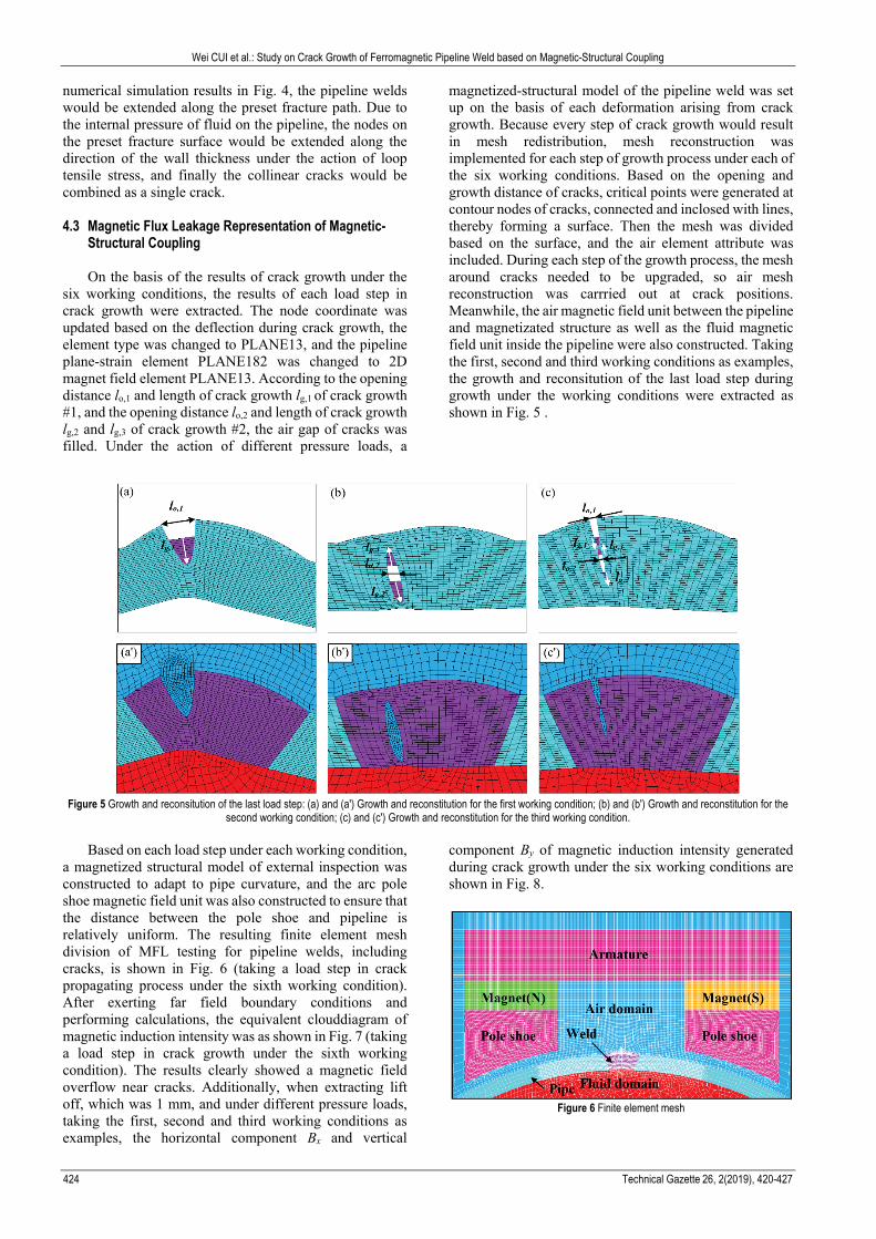
Structural Coupling On the basis of the results of crack growth under the
six working conditions, the results of each load step in crack growth were extracted. The node coordinate was updated based on the deflection during crack growth, the element type was changed to PLANE13, and the pipeline plane-strain element PLANE182 was changed to 2D magnet field element PLANE13. According to the opening distance lo,1 and length of crack growth lg,1 of crack growth #1, and the opening distance lo,2 and length of crack growth lg,2 and lg,3 of crack growth #2, the air gap of cracks was filled. Under the action of different pressure loads, a
magnetized-structural model of the pipeline weld was set up on the basis of each deformation arising from crack growth. Because every step of crack growth would result in mesh redistribution, mesh reconstruction was implemented for each step of growth process under each of the six working conditions. Based on the opening and growth distance of cracks, critical points were generated at contour nodes of cracks, connected and inclosed with lines, thereby forming a surface. Then the mesh was divided based on the surface, and the air element attribute was included. During each step of the growth process, the mesh around cracks needed to be upgraded, so air mesh reconstruction was carrried out at crack positions. Meanwhile, the air magnetic field unit between the pipeline and magnetizated structure as well as the fluid magnetic field unit inside the pipeline were also constructed. Taking the first, second and third working conditions as examples, the growth and reconsitution of the last load step during growth under the working conditions were extracted as shown in Fig. 5 .
Figure 5 Growth and reconsitution of the last load step: (a) and (a') Growth and reconstitution for the first working condition; (b) and (b') Growth and reconstitution for the
second working condition; (c) and (c') Growth and reconstitution for the third working condition.
Based on each load step under each working condition, a magnetized structural model of external inspection was constructed to adapt to pipe curvature, and the arc pole shoe magnetic field unit was also constructed to ensure that the distance between the pole shoe and pipeline is relatively uniform. The resulting finite element mesh division of MFL testing for pipeline welds, including cracks, is shown in Fig. 6 (taking a load step in crack propagating process under the sixth working condition). After exerting far field boundary conditions and performing calculations, the equivalent clouddiagram of magnetic induction intensity was as shown in Fig. 7 (taking a load step in crack growth under the sixth working condition). The results clearly showed a magnetic field overflow near cracks. Additionally, when extracting lift off, which was 1 mm, and under different pressure loads, taking the first, second and third working conditions as examples, the horizontal component Bx and vertical
component By of magnetic induction intensity generated during crack growth under the six working conditions are shown in Fig. 8.
Figure 6 Finite element mesh

Wei CUI et al.: Study on Crack Growth of Ferromagnetic Pipeline Weld based on Magnetic-Structural Coupling
Tehnički vjesnik 26, 2(2019), 420-427 425
Figure 7 Clouddiagram of magnetic induction intensity
The peak values of horizontal component Bx and
vertical component By of magnetic induction intensity generated under the six working conditions were extracted as shown in Fig. 8(a)÷(c). The changing peak values, as well as other characteristic values (such as opening distance lo,1 and growth length lg,1 of cracks #1, and opening distance lo,2 and growth length lg,2 of crack tip #2, and growth length lg,3 of crack tip #3) during crack growth and
under various pressure loads is shown in Fig. 9. The critical data during crack growth are shown in Tab. 3. In this table, Pb
x represents growth pressure, Pcx represents pressure
before fracture and Pdx represents the different pressure
loads; regions I, Ⅱ and Ⅲ are shown in Fig. 9. 4.4 Discriminatory Analysis
It can be seen from Fig. 8 that the wave crest and
trough positions for cracks correspond to the cracks in pipeline welds. Based on the wave crest and trough positions, the positions at circumferential directions of cracks on pipeline welds can be judged as 1/2 or 1. Additionally, with the increase in internal pressure applied by the fluid in the pipeline on the pipeline, the peak values of horizontal component Bx and vertical component By of magnetic induction intensity in leakage magnetic field also increased. This was because the crack growth opening distance lo increased as internal pressure increased, driving crack growth. When the pressure load was increased to a certain value the cracks would extend, with growth length lg increasing with the increase in pressure. From Fig. 9 it can be clearly seen that each characteristic value increased with the increased pressure load.
Figure 8 Horizontal component Bx and vertical component By of magnetic induction intensity
Figure 9 Characteristic values under various pressure loads
As shown in the first region of all working conditions
in Fig. 9, when GI is less than the critical value GIC, the cracks did not extend; when GI > GIC, the cracks extended and entered the second region of stable growth. When GI continued to increase, the cracks entered rapid growth region III, which is the unstable fracture region; by this time, the pipeline could be damaged and fractured under a small load. The crack growth process and danger classes are also shown in Fig. 9. It can be seen from Tab. 3 that the
opening distance of cracks on the outer pipeline wall under working conditions 1 and 4 had a relatively large range: the maximum value of lo,1 under working condition 1 was 4.3104 mm and the maximum value of lo,1 under working condition 4 was 4.8040 mm. The opening distance lo,2 of the crack inside pipeline welds during growth under working conditions 2 and 5 had a small range: the maximum value of lo,2 under working condition 2 was 1.3519 mm and the maximum value lo,2 under working

Wei CUI et al.: Study on Crack Growth of Ferromagnetic Pipeline Weld based on Magnetic-Structural Coupling
426 Technical Gazette 26, 2(2019), 420-427
condition 5 was 1.7596 mm. This was consistent with the detected magnetic induction intensity component curve of leakage magnetic field (Fig. 8). From Fig. 8, comparing the process of crack growth on the outer pipeline wall (working condition 1) and the process of crack growth inside the pipeline (working condition 2), the Bx wave peak span of the crack on the outer pipeline wall increased greatly, and the spacing of By wave peak and trough on the outer pipeline wall increased greatly. Hence, cracks on the outer wall of the pipeline and inside the pipeline could be identified based on the curve shape of the magnetic field induction intensity of leakage magnetic field.
It can be also seen from Tab. 3 that: (1) When the cracks occurred at different positions in
the circumferential direction of pipeline welds, the load was extended gradually such that Pb
1<Pb4, Pb
2<Pb5 and
Pb3<Pb
6, depending on whether they were cracks in the
outer wall, internal cracks or multiple collinear cracks; cracks that were far from the center of the weld were easily extended. Hence, danger classes based on the position of cracks could be assigned.
(2) When the cracks were at different positions in the radial direction of pipeline welds, Pb
1>Pb3, Pb
2>Pb3,
Pb4>Pb
6 and Pb5>Pb
6, depending on whether the cracks were at the 1/2 arc length position from the heat affected zone to the weld centre or at the centre of the weld bead; multiple cracks were more easily extended.
(3) The differential pressure loads were Pd1>Pd
3, Pd
2>Pd3, Pd
4>Pd6 and Pd
5>Pd6; when multiple cracks began
to extend and prior to fracture, the differential pressure load was small, the growth rate was rapid and there were fewer growth steps. Therefore, multiple and single cracks could be distinguished based on the growth rate.
Table 3 Critical data of characteristic values during crack growth
Conditions/Parameters 1 2 3 4 5 6 Pressure for beginning to grow Pb/MPa Pb
1: 21.6534 Pb2: 22.2534 Pb
3: 20.4534 Pb4: 23.7534 Pb
5: 23.4534 Pb6: 21.9534
Pressure before fracture Pc /MPa Pc1: 24.4731 Pc
2: 24.8208 Pc3: 20.7339 Pc
4: 27.8427 Pc5: 26.3673 Pc
6: 22.9932 Differential pressure loads Pd /MPa Pd
1: 2.8197 Pd2: 2.5674 Pd
3: 0.2805 Pd4: 4.0893 Pd
5: 2.9139 Pd6: 1.0398
Region Ⅰ lo,1max /mm 0.1906 − 0.1799 0.1574 − 0.1435
lo,2max /mm − 0.1445 0.1312 − 0.1426 0.1321
lg,1 /mm 0 − 0 0 − 0 lg,2 /mm − 0 0 − 0 0 lg,3 /mm − 0 0 − 0 0 Bx
max /T 0.0808 0.0570 0.0910 0.0501 0.0361 0.0644 By
max /T −0.0467 −0.0579 −0.0418 0.0052 −0.0047 0.0088 Region Ⅱ Range of lo,1 /mm 0.2497÷0.4782 − 0.2418÷0.2830 0.2086÷0.4423 − 0.1963÷0.2407
Range of lo,2 /mm − 0.1728÷0.2833 0.1428÷0.1922 − 0.1693÷0.3147 0.1429÷0.1989 Range of lg,1 /mm 0.2362÷0.7159 − 0.2362÷0.2344 0.2387÷0.7196 − 0.2390÷0.2375 Range of lg,2 /mm − 0.2523÷0.5008 0÷0.2539 − 0.2316÷0.6938 0÷0.2325 Range of lg,3 /mm − 0÷0.4606 0÷0.2337 − 0÷0.4699 0÷0.2370 Range of Bx /T 0.0912÷0.1233 0.0600÷0.0788 0.1028÷0.1143 0.0579÷0.0881 0.0394÷0.0633 0.0719÷0.0849 Range of By /T −0.0438÷−0.0237 −0.0558÷−0.0440 −0.0365÷−0.0292 0.0067÷0.0197 −0.0035÷0.0060 0.0111÷0.0172
Region Ⅲ Range of lo,1 /mm 0.7103÷4.3104 − 0.3473÷0.8052 0.6543÷4.8040 − 0.3087÷0.7924 Range of lo,2 /mm − 0.3189÷1.3519 0.2164÷0.4501 − 0.3517÷1.7596 0.2216÷0.4982 Range of lg,1 /mm 1.1968÷3.3671 − 0.4768÷0.9559 1.2021÷3.6002 − 0.4806÷0.9618 Range of lg,2 /mm − 0.7507÷2.5606 0.2541÷0.5134 − 0.9243÷2.9282 0.2325÷0.7066 Range of lg,3 /mm − 0.4597÷2.2645 0.2335÷0.7111 − 0.4693÷2.4308 0.2357÷0.7164 Range of Bx /T 0.1536÷0.2985 0.0850÷0.3010 0.1270÷0.2167 0.1176÷0.2624 0.0701÷0.3696 0.0965÷0.1964 Range of By /T −0.0032÷0.1535 −0.0401÷0.1069 −0.0212÷0.0353 0.0343÷0.1596 0.0086÷0.1665 0.0232÷0.07250
5 CONCLUSION
(1) A new magnetic-structural coupling algorithm that
can be applied to single crack and multiple cracks is proposed. Multiple crack growth simulation was implemented using VCCT. After calculating the duration of incremental crack growth, the geometrical shape of cracks was upgraded and the mesh reconfigured, in conjunction with magnetic field analysis, to achieve magnetic-structural coupling. This approach was applied to six typical working conditions, of which the initial length lc was 2 mm.
(2) According to growth results, cracks that were further from the weld centre extended more easily, informing the assignment of crack risk classes based upon the position of cracks. Through the peak value position of the magnetic induction intensity component of the leakage magnetic field of cracks in different circumferential direction positions, the damaged parts of pipeline welds could be determined. The opening distance lo,1 of cracks on the outer wall of pipe welds during growth had a large
range, while the opening distance lo,2 of cracks inside pipe welds during growth had a small range. These values were consistent with the detected curve shape of magnetic field induction intensity of the leakage magnetic field. Cracks on the outer wall of the pipeline and inside the pipeline can therefore be identified based on the curve shape of magnetic field induction intensity of the leakage magnetic field. When the same radial position of pipe welds contained cracks, multiple cracks were easily and rapidly expanded, therefore multiple and single cracks can be identified based on their growth rate.
(3) Six working conditions were used as examples in this paper based on the principle of MFL and VCCT, demonstrating the applicability of this approach to various conditions, such as multiple cracks. With an increase in the number of cracks, the interaction between cracks had a more obvious effect. This method also provides a theoretical basis for the subsequent research on the dynamic crack growth of the pipeline weld.

Wei CUI et al.: Study on Crack Growth of Ferromagnetic Pipeline Weld based on Magnetic-Structural Coupling
Tehnički vjesnik 26, 2(2019), 420-427 427
Acknowledgements This work was sponsored by the National Natural
Science Foundation of China (51607035, 51774091, 11502051, 51674090) and China Postdoctoral Science Foundation (2018M641804, 2018T110268) and Heilongjiang Youth Innovation Talents of Ordinary Undergraduate Colleges and Universities (UNPYSCT-2018046) and Heilongjiang Postdoctoral Research Foundation (LBH-Q18029) and Heilongjiang Postdoctoral Foundation (LBH-Z16040) and Science and Technology Project of China Petroleum and Chemical Industry Association (2017-11-04) and Research start-up fund of Northeast Petroleum University (rc201732). All these are gratefully appreciated. 6 REFERENCES [1] Shi, L. Y. & Yu, T. T. (2014). Analysis of multiple crack
growth using extended finite element method. Rock and Soil Mechanics, 35(1), 263-272. https://doi.org/10.16285/j.rsm.2014.01.001
[2] Yang, S. K., Zhang, J. X., Ren, X. H., & Zhang, D. F. (2016). Application of three-dimensional numerical manifold method to crack propagation. Rock and Soil Mechanics, 37(10), 3017-3025. https://doi.org/10.16285/j.rsm.2016.10.037
[3] Ahn, J. S. & Woo, K. S. (2015). Delamination of laminated composite plates by p-convergent partial discrete-layer elements with VCCT. Mechanics Research Communications, 66(6), 60-69. https://doi.org/10.1016/j.mechrescom.2015.02.009
[4] Sghayer, A., Grbović, A., Sedmak, A., Dinulović, M., Grozdanović, I., Sedmak, S., & Petrovski, B. (2018). Experimental and Numerical Analysis of Fatigue Crack Growth in Integral Skin-Stringer Panels. Tehnicki Vjesnik-Technical Gazette, 25(3), 785-791. https://doi.org/10.17559/TV-20170308110329
[5] Aldarwish, M., Grbovic, A., Kastratovic, G., Sedmak, A., & Vidanovic, N. (2017). Numerical Assessment of Stress Intensity Factors at Tips of Multi-Site Cracks in Unstiffened Panel. Structural Integrityand Life, 17(1), 11-14.
[6] Aldarwish, M., Grbović, A., Kastratović, G., Sedmak, A., & Lazić, M. (2018). Stress Intensity Factors Evaluation at Tips of Multi-Site Cracks in Unstiffened 2024-T3 Aluminium Panel Using XFEM. Tehnicki Vjesnik-Technical Gazette, 25(6), 1616-1622. https://doi.org/10.17559/TV-20170309133824
[7] Yang, S. K., Ren, X. H, & Zhang, J. X. (2018). Application of enriched numerical manifold method to hydraulic fracture. Rock and Soil Mechanics, 39(10), 3875-3881. https://doi.org/10.16285/j.rsm.2018.0448
[8] Li, W., Zheng, H., Chen, Y. Q., Lin, S., & Sun, Y. H. (2018). Application of the MLS based enriched numerical manifold method in dynamic crack propagation. Chinese Journal of Rock Mechanics and Engineering, 37(7), 1574-1585. https://doi.org/10.13722/j.cnki.jrme.2018.0031
[9] Meng, L. B. & Chen, P. H. (2010). Virtual crack closure technique for delamination growth analysis of laminated composites and its application. Acta Materiae Compositae Sinica, 27(1), 190-195. https://doi.org/10.13801/j.cnki.fhclxb.2010.01.025
[10] Cui, W., Wang, K., Zhang, Q., & Zhang, P. (2017). A Recognition Algorithm to Detect Pipe Weld Defects. Tehnicki Vjesnik-Technical Gazette, 24(6), 1969-1975. https://doi.org/10.17559/TV-20170523211205
[11] Latifi, M., Meer, F. P. V. D., & Sluys, L. J. (2015). A level set model for simulating fatigue-driven delamination in
composites. International Journal of Fatigue, 80(11), 434-442. https://doi.org/10.1016/j.ijfatigue.2015.07.003
[12] Magi, F., Maio, D. D., & Sever, I. (2017). Validation of initial crack propagation under vibration fatigue by Finite Element analysis. International Journal of Fatigue, 104(11), 183-194.https://doi.org/10.1016/j.ijfatigue.2017.07.003
[13] Jokinen, J. & Kanerva, M. (2017). Analysis of cracked lap shear testing of tungsten-CFRP hybrid laminates. Engineering Fracture Mechanics, 175(4), 184-200. https://doi.org/10.1016/j.engfracmech.2017.01.029
[14] Riccio, A., Damiano, M, Raimondo, A., Felice, G. D., & Sellitto, A. (2016). A fast numerical procedure for the simulation of inter-laminar damage growth in stiffened composite panels. Composite Structures, 145(6), 203-216. https://doi.org/10.1016/j.compstruct.2016.02.081
[15] Naini, J. K. & Ramesh, B. P. (2016). Impact Analysis of Embedded Delamination Location in Hybrid Curved Laminated Composite Stiffened Panel. Applied Composite Materials, 23(4), 1-20. https://doi.org/10.1007/s10443-016-9478-3
[16] Amiri-Rad, A., Mashayekhi, M., & Meer, F. P. V. D. (2017). Cohesive zone and level set method for simulation of high cycle fatigue delamination in composite materials. Composite Structures, 160(1), 61-69. https://doi.org/10.1016/j.compstruct.2016.10.041
Contact information: Wei CUI, Associate Professor Corresponding author Northeast Petroleum University, Daqing high-tech development zone University Street NO. 99, Daqing City, Heilongjiang Province, China E-mail: [email protected] Rixuan SONG, Postgraduate Northeast Petroleum University, Daqing high-tech development zone University Street NO. 99, Daqing City, Heilongjiang Province, China E-mail: [email protected] Ziming FENG, Professor Northeast Petroleum University, Daqing high-tech development zone University Street NO. 99, Daqing City, Heilongjiang Province, China E-mail: [email protected] Qiang ZHANG, Associate Professor Northeast Petroleum University, Daqing high-tech development zone University Street NO. 99, Daqing City, Heilongjiang Province, China E-mail: [email protected] Zhipeng MA, Professor Northeast Petroleum University, Daqing high-tech development zone University Street NO. 99, Daqing City, Heilongjiang Province, China E-mail: [email protected]