Study of vehicle BCI test for UN R10 - UNECE
17
Study of vehicle BCI test for UN R10 1. Outline 2. Proposal 3. Correlation method 4. Result 5. Conclusion 31th, Oct. 2017 Japan Automobile Manufacturers Association, Inc. OICA EMC T/F Roadmap proposal JAMA
Transcript of Study of vehicle BCI test for UN R10 - UNECE

Study of vehicle BCI test
for UN R10
1. Outline
2. Proposal
3. Correlation method
4. Result
5. Conclusion
31th, Oct. 2017 Japan Automobile Manufacturers Association, Inc.
OICA EMC T/F Roadmap proposal JAMA

1. Outline
Vehicle immunity method of UN-R10-05 is defined ALSE method as
reference test method.
And vehicle BCI test method is defined as alternating method limited only
large vehicle.
However, if test vehicle has a little objective items(components) for the test,
BCI test will be very efficient test method.
JAMA proposes that vehicle BCI test can be applied not only large vehicle
but also whole vehicles with demonstration by comparison between ALSE
and BCI test method.

2. Proposal
ANNEX 6
1.3. Alternative test methods
The test may be alternatively performed in an outdoor test site for all
vehicles. The test facility shall comply with (national) legal requirements
regarding the emission of electromagnetic fields.
If a vehicle is longer than 12 m and/or wider than 2.60 m and/or higher than
4.00 m, BCI (bulk current injection) method according to ISO 11451-4 shall
can be used in the frequency range 20 to 2,000 MHz with levels defined in
paragraph 6.8.2.1. of this Regulation.
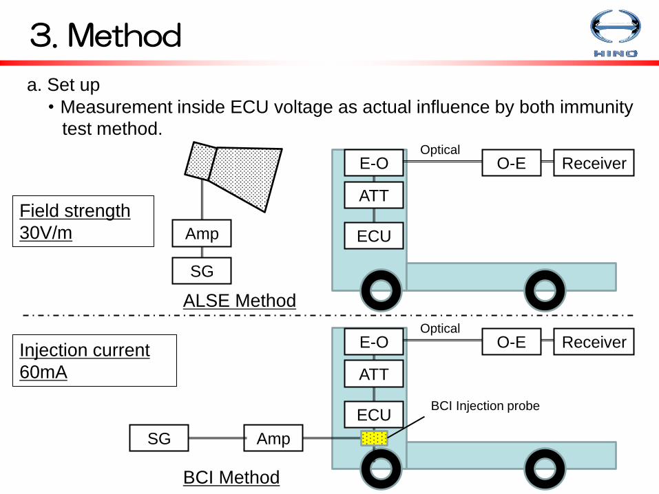
3. Method
a. Set up
・Measurement inside ECU voltage as actual influence by both immunity
test method.
ECU
ATT
E-O O-E Receiver Optical
Amp
SG
ECU
ATT
E-O O-E Receiver Optical
Amp SG
BCI Injection probe
ALSE Method
BCI Method
Field strength
30V/m
Injection current
60mA

3. Correlation method
b. Test ECU and Optical link
Test ECU
3 measurement port
(SMA) is installed.
Port 1: Power line
Port2 : Analog sensor
Port3 : CAN line
Optical transmitter
system Connected to
Test ECU Optical reciever

3. Correlation method
c. About optical link
To avoid influence the metallic cable, test was used a optical RF
transmitter system.
OPTICAL FEEDING RADIO OVER
FIBER RECEIVAR SYSTEM
Items Specifications Remark
Frequency range 100kHz~6GHz
Gain -10dB以上 @1GHz
Flatness 100kHz~6GHz:±6dB
10MHz~6GHz :+6dB/-3dB Reference of gain@1GHz
Harmonics distortion 25dBc以上 2 and 3 times of fundamental at input
level -22dBm
SNR 40dB以上 Conversion by RBW=1Hz、
@Transmitter input level =-72dBm
Make : TAMAGAWA ELECTRICS
Optical receiver : EOS-1000
Controller : OAL-1000

4. Result
Location
Circuit load
Around the
Meter cluster Instrument panel Chassis mount
Power line Figure 1. Figure 2. Figure 3.
Analog sensor Figure 4. Figure 5. Figure 6.
CAN line Figure 7. Figure 8. Figure 9.
ALSE
method
Meter
cluster
Instrument
panel
Chassis
mount

4. Result
Figure 1. Around a Meter cluster / Power line

4. Result
Figure 2. Instrument panel / Power line

4. Result
Figure 3. Chassis mount / Power line

4. Result
Figure 4. Around a Meter cluster / Analog sensor
Around a Meter cluster / Analog sensor

4. Result
Figure 5. Instrument panel / Analog sensor

4. Result
Figure 6. Chassis mount / Analog sensor

4. Result
Figure 7. Around a Meter cluster / CAN line

4. Result
Figure 8. Instrument panel / CAN line

4. Result
Figure 9. Chassis mount / CAN line

5. Conclusion
・BCI test is more strict than ALSE method at all ECU locations and circuit
loads. That means BCI test can cover the ALSE test method.
・When number of objective components (systems) is little, vehicle BCI test
method will be very efficiency test method. (Time, Cost, Location…)
・Vehicle BCI test method is suitable as alternative immunity test method.