Study of High Field Superconducting Solenoids for Muon ...
5
4L01 1 Study of High Field Superconducting Solenoids for Muon Beam Cooling V. V. Kashikhin, E. Barzi, V. S. Kashikhin, M. Lamm, Y. Sadovskiy, and A. V. Zlobin Abstract—The final beam cooling stages of a possible Muon Collider may require DC solenoid magnets with magnetic fields of 40-50 T in an aperture of 40-50 mm. In this paper we study possible solutions towards creating DC fields of that order using available superconductors. Several magnetic and mechanical designs, optimized for the maximum performance are presented and compared in terms of cost and size. Index Terms—superconductor, solenoid, high magnetic field, muon collider. I. INTRODUCTION ENERATION of very high steady state magnetic fields has had a continuous interest in scientific community. A resistive, 33 T Florida-Bitter solenoid and a hybrid, 45 T superconducting solenoid with a resistive insert have been built and operated at NHMFL [1], constituting the world’s records on constant magnetic fields created by resistive and hybrid magnets. However, the multi-megawatt power consumption can not justify the resistive magnet approach for continuously powered accelerator systems. Advances in high temperature superconducting (HTS) materials with the upper critical fields over 90 T gave opportunity to consider them in the high field solenoid design. Several coil inserts made of Bi 2 Sr 2 Ca 2 Cu 3 O 10+x (Bi-2223) and Bi 2 Sr 2 CaCu 2 O 8+x (Bi-2212) superconductors with the bore contribution of up to 5 T were produced and successfully tested with background coils in 24-25 T configurations [2]- [4], demonstrating the feasibility of HTS inserts. In this paper we study the possibility of extending the bore field to 40-50 T using available superconductors. The resistive coil inserts or outserts are not considered for economical reasons. In order to achieve the maximum performance at a minimum cost, the magnet is subdivided into HTS and low temperature superconducting (LTS) sections, both operating at a liquid helium temperature that is similar to suggested in [5]- [6]. However, the coil optimization strategy and structural design approach are different, as noted in the following text. Manuscript received August 27, 2007. This work was supported by the U.S. Department of Energy. E. Barzi, V. V. Kashikhin, V. S. Kashikhin, M. Lamm and A. V. Zlobin are with the Fermilab, P.O. Box 500, Batavia, IL 60510, USA (phone: 630-840- 6546; fax: 630-840-3369; e-mail: [email protected]). Y. Sadovskiy was with the Fermilab, P.O Box 500, Batavia, IL 60510, USA. He is now with Moscow Engineering Physics Institute, Moscow, Kashirskoe Shosse 31, Russia (e-mail: [email protected]). II. CONDUCTOR AND INSULATION A. HTS section Most of the HTS insert coils built up to day used either Bi- 2223 or Bi-2212 tapes. Both materials have relatively well defined electromechanical properties and available in sufficiently long piece-lengths. In this study we primarily focus on Bi-2223 tapes that are available with stainless steel reinforcements from American Superconductor, but has field anisotropy and Bi-2212 round wire from OST that has higher engineering current density and isotropic, but not reinforced. Recent advances in the YBa 2 Cu 3 O 7 (YBCO) conductor development made it a viable candidate for high field solenoid. However, it is not considered in this study because of still short piece-length and not well known mechanical properties. To access the anisotropy of Bi-2223 tape, the short sample measurements were performed in 0-15 T field range for 0-90 degrees field angles [7]. It was found that the ratio of critical currents in the parallel over perpendicular field has a slightly negative slope as a function of applied field at 4.2 K temperature. Thus fixing that ratio at 15 T value gave a conservative estimate on the amount of anisotropy at higher fields. The measured field and angle dependences were parameterized by analytical functions and extrapolated to higher fields using the data on Bi-2212 wire, measured up to 45 T field [8]. The “high strength plus” tape from American superconductor was selected for the solenoid design because of combined high engineering current density and good mechanical properties. The corresponding scale factor was introduced into the analytical parameterization to account for the increase in the current density over the “hermetic” wire. For the purpose of this study it was assumed that the amount of electrical insulation in the HTS section is 15 %. For the 0.285 mm thick tape it corresponds to the layer to layer insulation thickness of ~50 µm. The insulation options may include PTFE or Kapton wrap applied to the tape, interlayer Kapton sheet or fiberglass cloth or oxide coated stainless steel tape. The latter insulation, successfully applied in the 5 T HTS insert [4], would provide the highest elasticity modulus of the coil assembly. The HTS coils are to be impregnated with epoxy resin that prevents penetration of liquid helium into the tape, thus eliminating the need for a “hermetic” wire, and provides the coil structural integrity necessary for the 50 T applications as G FERMILAB-CONF-07-429-TD
Transcript of Study of High Field Superconducting Solenoids for Muon ...

4L01
1
Study of High Field Superconducting Solenoids for Muon Beam Cooling
V. V. Kashikhin, E. Barzi, V. S. Kashikhin, M. Lamm, Y. Sadovskiy, and A. V. Zlobin
Abstract—The final beam cooling stages of a possible Muon
Collider may require DC solenoid magnets with magnetic fields of 40-50 T in an aperture of 40-50 mm. In this paper we study possible solutions towards creating DC fields of that order using available superconductors. Several magnetic and mechanical designs, optimized for the maximum performance are presented and compared in terms of cost and size.
Index Terms—superconductor, solenoid, high magnetic field, muon collider.
I. INTRODUCTION ENERATION of very high steady state magnetic fields has had a continuous interest in scientific community. A
resistive, 33 T Florida-Bitter solenoid and a hybrid, 45 T superconducting solenoid with a resistive insert have been built and operated at NHMFL [1], constituting the world’s records on constant magnetic fields created by resistive and hybrid magnets. However, the multi-megawatt power consumption can not justify the resistive magnet approach for continuously powered accelerator systems.
Advances in high temperature superconducting (HTS) materials with the upper critical fields over 90 T gave opportunity to consider them in the high field solenoid design. Several coil inserts made of Bi2Sr2Ca2Cu3O10+x (Bi-2223) and Bi2Sr2CaCu2O8+x (Bi-2212) superconductors with the bore contribution of up to 5 T were produced and successfully tested with background coils in 24-25 T configurations [2]-[4], demonstrating the feasibility of HTS inserts.
In this paper we study the possibility of extending the bore field to 40-50 T using available superconductors. The resistive coil inserts or outserts are not considered for economical reasons. In order to achieve the maximum performance at a minimum cost, the magnet is subdivided into HTS and low temperature superconducting (LTS) sections, both operating at a liquid helium temperature that is similar to suggested in [5]-[6]. However, the coil optimization strategy and structural design approach are different, as noted in the following text.
Manuscript received August 27, 2007. This work was supported by the
U.S. Department of Energy. E. Barzi, V. V. Kashikhin, V. S. Kashikhin, M. Lamm and A. V. Zlobin are
with the Fermilab, P.O. Box 500, Batavia, IL 60510, USA (phone: 630-840-6546; fax: 630-840-3369; e-mail: [email protected]).
Y. Sadovskiy was with the Fermilab, P.O Box 500, Batavia, IL 60510, USA. He is now with Moscow Engineering Physics Institute, Moscow, Kashirskoe Shosse 31, Russia (e-mail: [email protected]).
II. CONDUCTOR AND INSULATION
A. HTS section Most of the HTS insert coils built up to day used either Bi-
2223 or Bi-2212 tapes. Both materials have relatively well defined electromechanical properties and available in sufficiently long piece-lengths. In this study we primarily focus on Bi-2223 tapes that are available with stainless steel reinforcements from American Superconductor, but has field anisotropy and Bi-2212 round wire from OST that has higher engineering current density and isotropic, but not reinforced. Recent advances in the YBa2Cu3O7 (YBCO) conductor development made it a viable candidate for high field solenoid. However, it is not considered in this study because of still short piece-length and not well known mechanical properties.
To access the anisotropy of Bi-2223 tape, the short sample measurements were performed in 0-15 T field range for 0-90 degrees field angles [7]. It was found that the ratio of critical currents in the parallel over perpendicular field has a slightly negative slope as a function of applied field at 4.2 K temperature. Thus fixing that ratio at 15 T value gave a conservative estimate on the amount of anisotropy at higher fields. The measured field and angle dependences were parameterized by analytical functions and extrapolated to higher fields using the data on Bi-2212 wire, measured up to 45 T field [8]. The “high strength plus” tape from American superconductor was selected for the solenoid design because of combined high engineering current density and good mechanical properties. The corresponding scale factor was introduced into the analytical parameterization to account for the increase in the current density over the “hermetic” wire.
For the purpose of this study it was assumed that the amount of electrical insulation in the HTS section is 15 %. For the 0.285 mm thick tape it corresponds to the layer to layer insulation thickness of ~50 µm. The insulation options may include PTFE or Kapton wrap applied to the tape, interlayer Kapton sheet or fiberglass cloth or oxide coated stainless steel tape. The latter insulation, successfully applied in the 5 T HTS insert [4], would provide the highest elasticity modulus of the coil assembly.
The HTS coils are to be impregnated with epoxy resin that prevents penetration of liquid helium into the tape, thus eliminating the need for a “hermetic” wire, and provides the coil structural integrity necessary for the 50 T applications as
G
FERMILAB-CONF-07-429-TD

4L01
2
shown in the structural analysis section. Due to the low amount of porosity, the Kapton and coated stainless steel insulation options may need to undergo the “wet” winding process to ensure the good epoxy penetration, while the fiberglass insulated coil can be vacuum impregnated after winding.
The round Bi-2212 wire has ~30 % higher engineering current density than the Bi-2223 “high strength plus” tape in the parallel field [8]. This could provide ~15-20 % higher average current density with respect to the tape if the round wires are composed into a Rutherford type cable. However, the relatively large cabling degradation measured in present Bi-2212 wires and cables [9] advises against this option. Thus, it was assumed that coils are wound from the round wire.
The compaction factor of a coil made from round wire depends on the winding pattern and insulation material. Since the preferred insulation type is not known at the moment, it was conservatively assumed that the insulation is rigid enough (e.g., coated stainless steel tape) so the wire does not follow the “grooves” of preceding layer. In this case the theoretical compaction factor (not accounting for the insulation) is π/4=0.78. Also, the round wires may likely require extra coating in addition to the interlayer insulation that would reduce the compaction factor down to ~0.7 that brings the average current density to essentially the same level as in Bi-2223 tape winding. So, for the purpose of this paper, the current density in Bi-2212 winding is chosen the same as in Bi-2223 tape in the parallel field and the amount of interlayer insulation in the HTS section is also 15 %.
B. LTS section The materials considered for the LTS section included
Nb3Sn and NbTi wires. The critical current density in non-Cu fraction of the wires was fixed at 2700 A/mm2 at 4.2 K temperature and 12 T field for Nb3Sn and 5 T field for NbTi that is ~10 % lower than in the best commercially available conductors, accounting for a possible deformation degradation. The Cu to non-Cu ratios were preliminary fixed at 1.0 for Nb3Sn and 1.5 for NbTi. That numbers are to be confirmed by the quench protection analysis. The critical current densities at other fields were parameterized by analytical functions [10]-[11].
It was assumed that the wires are either flattened before winding (Nb3Sn) or ordered in rectangular shape (NbTi) or composed into a Rutherford type cable, so the bare wire compaction factor is at least 0.85. It was further assumed that the fraction of electrical insulation is the same as in HTS section that brings the overall compaction factor down to 0.7.
III. MAGNET OPTIMIZATION
A. Model description A ~50 T solenoid would not considerably benefit from a
ferromagnetic yoke that, if present, would mostly act as a fringe field screen. It gives opportunity to analytically calculate the magnetic fields that was done by a parametric
model. The solenoid cross-section was subdivided to a number of turns and the total field was calculated as the superposition of all turn fields. The number of subdivisions was adjusted in order to achieve the desired calculation accuracy (10-3). It was determined that for our particular problem this approach provides faster convergence than a general solution of the finite solenoid field [12] at the same calculation accuracy.
To maximize the coil efficiency it was assumed that each coil section operates at its own minimum critical current density determined by the field in that section. In practice this can be achieved by adjusting the wire dimensions so that all sections operate at the same current or powering each section from an individual power supply. The former option requires only one pair or current leads and one power supply, while the latter option may be preferred for the quench protection.
In order to find the optimum coil configurations, the relative cost factors were introduced. It was assumed that the relative volumetric costs of bare wires are: 1 m-3 for NbTi, 10 m-3 for Nb3Sn and 20 m-3 for HTS that is consistent with average present costs of superconducting materials [13]-[14].
B. Optimization procedure and results The coil optimization was performed for two commonly
used criteria. The first one was the minimum cost of superconducting wires in the coil that involved minimizing the cost function under the Bbore = 50 T constraint. An objective function containing the sum of superconductor costs from each section was used for that purpose. The second criterion was the minimum coil volume that involved minimizing the objective function containing the sum of all section volumes under the same constraint.
All optimization was done for the Bi-2223 tape parameters, selected as the baseline conductor for the purposes of this study. However, the results are equally applicable to the round Bi-2212 wire that, depending on the field angle, would have the same or larger critical current density as the tape as discussed in the previous section.
The innermost coil length was fixed at 1 m and the inner coil diameter was fixed at 54 mm to have the clear bore diameter of 40 mm. The lengths and radial dimensions of all subsequent sections were varied during optimization to minimize the objective functions. The analytical optimization was iterated with numerical structural analysis described in the following section that guided the number of coil subsections and dimensions of structural elements necessary to limit the mechanical stresses at an acceptable value.
1) Minimum cost criterion
The 50 T solenoid quarter cross-section with magnetic flux lines optimized for the minimum superconductor cost criterion is shown in Fig. 1 (left). After a number of iterations with structural analysis it was determined that the HTS coil should be subdivided into five sections and the Nb3Sn and NbTi coils should have one section each. It may look surprising that in spite of the HTS tape anisotropy,

4L01
3
the optimum design has the same length of all sections. The reason of that becomes clear from the plot of engineering critical current density (with corresponding packing factors) along the inner surface of each subsection in Fig. 1 (right). The current density grows towards the end for the first two subsections, is approximately constant for the third and decays for the outer two subsections, where the field angle is sufficiently large for the anisotropy to play a role.
However, the current density reduction in the outermost HTS section end with respect to the center is only ~20 %. In comparison, the critical current density reduction in NbTi section is a factor of ~10 due to the “zero field” region in the middle of that section. The field angle with respect to the tape in the outer HTS section end is ~45 degrees that should be reduced to the field angle seen in the middle section end (i.e., by a factor of ~2) to eliminate the effect of anisotropy. That would require extending the LTS sections by ~50 % for the end benefit of 20 % higher current density in one and 10 % higher current density in another section out of seven. For the measured Bi-2223 properties and magnet length the advantage of higher critical current density in these two sections did not outweigh the cost increase due to longer LTS sections. However, the magnets made of HTS tape with larger degrees of anisotropy (e.g., YBCO) may economically benefit from adjusting the section length.
The main parameters of the minimum cost design are listed in Table I. The impact of HTS tape anisotropy is practically negligible that can be judged from only 2 % field increase when using the isotropic conductor, so the HTS material choice can be based on other, more substantial differences.
Fig. 1. Magnetic field distribution in the solenoid cross-section (left) and engineering critical current density along the inner section surfaces (right).
2) Minimum volume criterion
The coil optimization under the minimum volume criterion returned slightly different coil geometry as shown in Fig. 2 (left). Since the current density in NbTi conductor is smaller than that of Nb3Sn at any field, the NbTi section thickness turned to zero thus leaving only HTS and Nb3Sn materials in the coil. It was necessary to add one more HTS section in order to compensate the absence of NbTi section, so the total number of sections is the same as in the minimum cost coil.
However, the coil volume decreased by ~20 % and the superconductor cost increased by the same fraction with
respect to the minimum cost design. The optimum length of all coil sections turned out to be the same in spite of the HTS tape anisotropy due to the reason explained in the previous paragraph. The main parameters of the minimum volume design are listed in Table I.
It may look counterintuitive that the minimum volume magnet has larger stored energy than the bigger minimum cost design. The explanation lies in redistribution of current density as shown in Fig. 2 (right). Because the cost is not a constraint in the minimum volume design, a fraction of the current density is shuffled from the inner HTS section to the outer Nb3Sn section that result in more expensive, but smaller magnet. Consequently increases the field contribution of the outer section and thus larger volume gets filled with higher magnetic field, leading to increased stored energy.
Fig. 2. Magnetic field distribution in the solenoid cross-section (left) and engineering critical current density along the inner section surfaces (right).
TABLE I PARAMETERS OF THE SOLENOID MAGNETS. Minimization parameter Parameter Units
Cost Volume Coil inner diameter mm 54 Clear bore diameter mm 45 Cold mass length m 1014 Cold mass outer diameter mm 796 698 Quench field with Bi-2223 at 4.2 K T 50.35 50.77 Quench field with Bi-2212 at 4.2 K T 51.42 52.53 Integral Bzdz at 50 T field T⋅m 54.40 54.73 Stored energy at 50 T field MJ 79.3 89.55 Total conductor volume m3 0.348 0.223 Total superconductor cost m3
NbTi 2.64 3.24
C. Extrapolation to other fields In order to understand how the cost and size change versus
magnetic field, the optimized magnet designs were scaled to other fields in the 30-60 T range. The coils were analytically optimized according to the chosen criteria at each field level and the thicknesses of support cylinders were derived from magnet designs presented in previous paragraphs and scaled proportionally to the corresponding coil section thicknesses. Fig. 3 shows the magnet cost and outer diameter as functions of magnetic field for the two optimization criteria.
It is interesting to see that while the magnet diameter scales almost linearly with the bore field, the magnet cost change is between B3 and B4. It explains by increasing the relative fraction of the expensive HTS sections when the field goes up.

4L01
4
0
1
2
3
4
5
6
30 35 40 45 50 55 60B (T)
Cos
t (m
3 NbTi
)
0
100
200
300
400
500
600
Out
er ra
dius
(mm
)
CostOuter radius
0
1
2
3
4
5
6
7
30 35 40 45 50 55 60B (T)
Cos
t (m
3 NbTi
)
0
100
200
300
400
500
600
700
Out
er r
adiu
s (m
m)
CostOuter radius
Fig. 3. Superconductor costs and outer radii in solenoid magnets optimized with the minimum cost criterion (left) and minimum volume criterion (right).
IV. STRUCTURAL ANALYSIS The proposed structural concept involves splitting the coil
to a number of mechanically decoupled sections to prevent radial accumulation of Lorentz forces. Each section consists of the inner tube, the superconducting coil and the outer shell. A small part of the necessary mechanical prestress is provided by winding the conductor under tension. It was assumed that the tensile stress in all conductors is limited to 150 MPa during the winding. That number is chosen 30 % below the rated peak tensile stress of Bi-2223 “high strength” tape from American Superconductor at a room temperature. The remaining part of the prestress is delivered by straining the outer shells. Possible methods include winding the stainless steel tape or wire on top on the coils under tension, using differential thermal contraction, weld shrinking the shells, etc.
The traditional for accelerator magnets concept of limiting stresses in the coil to compression only is challenging to implement in a 50 T solenoid because of enormous density of Lorentz forces. Thus it was assumed that the coils work in compressive-tensile mode, switching from one to another during excitation. It was also assumed that there is a sufficient bonding and no gaps between conductors and support tubes.
The finite-element structural analysis was performed by Comsol Multiphysics code. It was iterated with the analytical optimization in order to limit the mechanical stresses (either tensile or compressive) in the conductors to 150 MPa at any condition. The average elasticity modulus was set to 40 GPa for all sections that represents elasticity modulus of initially preloaded composite coil consisting of conductor, insulation and epoxy with similar volumetric fractions [15]. The elasticity modulus of the HTS coil insulated with stainless steel tape would be a factor of two higher, reducing stresses during excitation. However, since the preferred insulation type is not known, it was conservatively assumed that the HTS coil has the same elasticity modulus as the LTS part. The support shells had mechanical properties of stainless steel. The effect of cooling down to liquid helium temperature was neglected.
Fig. 4 shows the stress components in the minimum cost design at 0 T and at 50 T. The optimization goal was achieved as the peak azimuthal (hoop) stress in the coil changes from 150 MPa of compression at 0 T to 150 MPa of tension at 50 T. All other stress components are below the target with the peak radial compression of 100 MPa at the inner coil surface at 0 T.
Fig. 4. Radial (top), azimuthal (middle) and axial (bottom) stresses at zero (left) and at 50 T field (right).
The peak axial stress in the coil is 150 MPa of compression at 50 T in the Nb3Sn section due to the large radial field component. The peak axial stresses in the HTS and NbTi parts are 115 MPa and 50 MPa respectively. The stresses in support shells are below 736 MPa at 0 T and 776 MPa at 50 T. These are considerably lower than the yield strength of cold reduced stainless steel at corresponding temperatures.
The optimum coil production technology may warrant heat treating the Nb3Sn and even the HTS coil modules after winding, as opposed to the react and wind method. In that case the inner support tubes made of cold rolled stainless steel would undergo a partial annealing that can reduce the material yield strength below the maximum stress level. In that case, higher strength materials with wide working temperature range, like Inconel alloy 706 may be used. This does not apply to the outer shells installed after the heat treatment.
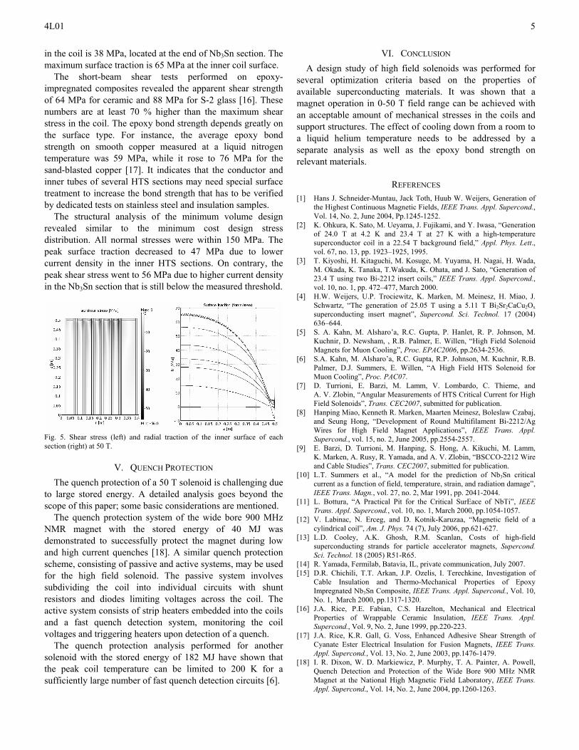
As it was already mentioned, the solenoid structural concept relies on a good bonding between the conductors and support structures. The maximum shear stress and surface traction (de-bonding stress) occurs at the maximum field. Fig. 5 shows these components at 50 T. The maximum shear stress
4L01
5
in the coil is 38 MPa, located at the end of Nb3Sn section. The maximum surface traction is 65 MPa at the inner coil surface.
The short-beam shear tests performed on epoxy-impregnated composites revealed the apparent shear strength of 64 MPa for ceramic and 88 MPa for S-2 glass [16]. These numbers are at least 70 % higher than the maximum shear stress in the coil. The epoxy bond strength depends greatly on the surface type. For instance, the average epoxy bond strength on smooth copper measured at a liquid nitrogen temperature was 59 MPa, while it rose to 76 MPa for the sand-blasted copper [17]. It indicates that the conductor and inner tubes of several HTS sections may need special surface treatment to increase the bond strength that has to be verified by dedicated tests on stainless steel and insulation samples.
The structural analysis of the minimum volume design revealed similar to the minimum cost design stress distribution. All normal stresses were within 150 MPa. The peak surface traction decreased to 47 MPa due to lower current density in the inner HTS sections. On contrary, the peak shear stress went to 56 MPa due to higher current density in the Nb3Sn section that is still below the measured threshold.
Fig. 5. Shear stress (left) and radial traction of the inner surface of each section (right) at 50 T.
V. QUENCH PROTECTION The quench protection of a 50 T solenoid is challenging due
to large stored energy. A detailed analysis goes beyond the scope of this paper; some basic considerations are mentioned.
The quench protection system of the wide bore 900 MHz NMR magnet with the stored energy of 40 MJ was demonstrated to successfully protect the magnet during low and high current quenches [18]. A similar quench protection scheme, consisting of passive and active systems, may be used for the high field solenoid. The passive system involves subdividing the coil into individual circuits with shunt resistors and diodes limiting voltages across the coil. The active system consists of strip heaters embedded into the coils and a fast quench detection system, monitoring the coil voltages and triggering heaters upon detection of a quench.
The quench protection analysis performed for another solenoid with the stored energy of 182 MJ have shown that the peak coil temperature can be limited to 200 K for a sufficiently large number of fast quench detection circuits [6].
VI. CONCLUSION A design study of high field solenoids was performed for
several optimization criteria based on the properties of available superconducting materials. It was shown that a magnet operation in 0-50 T field range can be achieved with an acceptable amount of mechanical stresses in the coils and support structures. The effect of cooling down from a room to a liquid helium temperature needs to be addressed by a separate analysis as well as the epoxy bond strength on relevant materials.
REFERENCES [1] Hans J. Schneider-Muntau, Jack Toth, Huub W. Weijers, Generation of
the Highest Continuous Magnetic Fields, IEEE Trans. Appl. Supercond., Vol. 14, No. 2, June 2004, Pp.1245-1252.
[2] K. Ohkura, K. Sato, M. Ueyama, J. Fujikami, and Y. Iwasa, “Generation of 24.0 T at 4.2 K and 23.4 T at 27 K with a high-temperature superconductor coil in a 22.54 T background field,” Appl. Phys. Lett., vol. 67, no. 13, pp. 1923–1925, 1995.
[3] T. Kiyoshi, H. Kitaguchi, M. Kosuge, M. Yuyama, H. Nagai, H. Wada, M. Okada, K. Tanaka, T.Wakuda, K. Ohata, and J. Sato, “Generation of 23.4 T using two Bi-2212 insert coils,” IEEE Trans. Appl. Supercond., vol. 10, no. 1, pp. 472–477, March 2000.
[4] H.W. Weijers, U.P. Trociewitz, K. Marken, M. Meinesz, H. Miao, J. Schwartz, “The generation of 25.05 T using a 5.11 T Bi2Sr2CaCu2Ox superconducting insert magnet”, Supercond. Sci. Technol. 17 (2004) 636–644.
[5] S. A. Kahn, M. Alsharo’a, R.C. Gupta, P. Hanlet, R. P. Johnson, M. Kuchnir, D. Newsham, , R.B. Palmer, E. Willen, “High Field Solenoid Magnets for Muon Cooling”, Proc. EPAC2006, pp.2634-2536.
[6] S.A. Kahn, M. Alsharo’a, R.C. Gupta, R.P. Johnson, M. Kuchnir, R.B. Palmer, D.J. Summers, E. Willen, “A High Field HTS Solenoid for Muon Cooling”, Proc. PAC07.
[7] D. Turrioni, E. Barzi, M. Lamm, V. Lombardo, C. Thieme, and A. V. Zlobin, “Angular Measurements of HTS Critical Current for High Field Solenoids”, Trans. CEC2007, submitted for publication.
[8] Hanping Miao, Kenneth R. Marken, Maarten Meinesz, Boleslaw Czabaj, and Seung Hong, “Development of Round Multifilament Bi-2212/Ag Wires for High Field Magnet Applications”, IEEE Trans. Appl. Supercond., vol. 15, no. 2, June 2005, pp.2554-2557.
[9] E. Barzi, D. Turrioni, M. Hanping, S. Hong, A. Kikuchi, M. Lamm, K. Marken, A. Rusy, R. Yamada, and A. V. Zlobin, “BSCCO-2212 Wire and Cable Studies”, Trans. CEC2007, submitted for publication.
[10] L.T. Summers et al., “A model for the prediction of Nb Sn critical current as a function of field, temperature, strain, and radiation damage”, IEEE Trans. Magn., v
3
ol. 27, no. 2, Mar 1991, pp. 2041-2044. [11] L. Bottura, “A Practical Pit for the Critical SurEace of NbTi”, IEEE
Trans. Appl. Supercond., vol. 10, no. 1, March 2000, pp.1054-1057. [12] V. Labinac, N. Erceg, and D. Kotnik-Karuzaa, “Magnetic field of a
cylindrical coil”, Am. J. Phys. 74 (7), July 2006, pp.621-627. [13] L.D. Cooley, A.K. Ghosh, R.M. Scanlan, Costs of high-field
superconducting strands for particle accelerator magnets, Supercond. Sci. Technol. 18 (2005) R51-R65.
[14] R. Yamada, Fermilab, Batavia, IL, private communication, July 2007. [15] D.R. Chichili, T.T. Arkan, J.P. Ozelis, I. Terechkine, Investigation of
Cable Insulation and Thermo-Mechanical Properties of Epoxy Impregnated Nb3Sn Composite, IEEE Trans. Appl. Supercond., Vol. 10, No. 1, March 2000, pp.1317-1320.
[16] J.A. Rice, P.E. Fabian, C.S. Hazelton, Mechanical and Electrical Properties of Wrappable Ceramic Insulation, IEEE Trans. Appl. Supercond., Vol. 9, No. 2, June 1999, pp.220-223.
[17] J.A. Rice, K.R. Gall, G. Voss, Enhanced Adhesive Shear Strength of Cyanate Ester Electrical Insulation for Fusion Magnets, IEEE Trans. Appl. Supercond., Vol. 13, No. 2, June 2003, pp.1476-1479.
[18] I. R. Dixon, W. D. Markiewicz, P. Murphy, T. A. Painter, A. Powell, Quench Detection and Protection of the Wide Bore 900 MHz NMR Magnet at the National High Magnetic Field Laboratory, IEEE Trans. Appl. Supercond., Vol. 14, No. 2, June 2004, pp.1260-1263.