Study of Countermeasure Systems for Leaks of...
7
Study of Countermeasure Systems for Leaks of Onscreen Content by Digital Video/Camera Shooting Masaki Fujikawa and Ryosuke Kamai Fumihiko Oda and Kengo Moriyasu Sohgo Security Services Co., Ltd.(ALSOK) Ushio Inc. Shingo Fuchi and Yoshikazu Takeda Hikaru Mori and Kenji Terada Nagoya University Tokushima University Abstract We have been engaged in the study of countermeasures to prevent the leak of onscreen content (texts, images and movies) using a digital video camera. One of the studies is the development of a transparent sheet that emits infrared (IR) light, which is applied to the screen and generates optical noise in the onscreen photographic images when recorded. Another study is the development of a method to detect video recording/camera shooting near the display as a countermeasure to prevent video recording using the IR-cut filter. This report is prepared as an advance report because it was confirmed that the feasibility of such countermeasures is enhanced. 1. Introduction With expanded use of cloud computing and enhanced functionality of the digital camera (large memory size, standard movie shooting function, and increased operability), sharing of the content (images and movies) taken by the digital camera with family members or friends and posting such content on video sites open to the general public are becoming popular among the people. Today, a wide variety of content is shared and open to the public and people are enjoining such content as a new style of entertainment. On the other hand, cases have been reported where content that should be treated as proprietary and confidential have been posted on movie sites open to the public [1], [2]. Because the LAN connected to the Internet or storage media like CDs, DVDs, and smart media are usually used for content leaks, countermeasures to prevent leakage, such as the introduction of a device that blocks the uploading of files using a specific protocol (ftp, http, etc.) or introduction of software that blocks the copying of content onto storage media are employed on PCs used in government and enterprise offices. The authors have been engaged in the study of content leaks in the area where no effective countermeasures were proposed (i.e., shooting/recording of the onscreen contents on the PC display by the digital camera and taking such contents to outside) [3], and a case of the content leak in such fashion was actually reported, which indicates the importance of such countermeasures [4]. In this case, an air traffic controller brought his digital camera to the control room and photo shot the confidential information on the flight plans of President Obama’s Air Force One and the US Air Force’s unmanned aerial reconnaissance plane Global Hawk displayed on the screens, and posted such images on his blog. The authors believe that, in order to counteract the above mentioned content leaks, countermeasures in two areas are required. One is development of a transparent sheet that emits IR light, which is attached to the screen and generates optical noise in onscreen photographic images when recorded (hereinafter called Countermeasure 1). Another one is development of the system that detects shooting of the screen in order to cope with shooting/recording using a IR cut-off filter, which nullifies the effect of the Countermeasure 1 (i.e., inclusion of the optical noise can be evaded. Hereinafter, we called Countermeasure 2). In this report, high feasibility of such countermeasures is indicated based on the descriptions about the detail of these countermeasures and the results of the experiments. 2. Development target setting First, the targets to be attained by respective countermeasures were determined based on several considerations. 2.1. Consideration 1 Infringement of copyright where a movie projected on the screen in the theater is recorded using a video camera, and the recorded data are duplicated on DVD or posted on a video site is becoming a problem [5]. As a countermeasure to prevent video recording by the audience, Yamada et al. proposed the projection of multiple beams of IR light from behind the screen to generate optical noise in the digital camera recording (degradation of the image) [6]. According to their report, the wavelength of IR light that is easily detected by the CCD and CMOS image sensors but not detected as visible Journal of Internet Technology and Secured Transactions (JITST), Volume 1, Issue 3, September 2012 Copyright © 2012, Infonomics Society 79
Transcript of Study of Countermeasure Systems for Leaks of...
Study of Countermeasure Systems for Leaks of Onscreen Content by
Digital Video/Camera Shooting
Masaki Fujikawa and Ryosuke Kamai Fumihiko Oda and Kengo Moriyasu
Sohgo Security Services Co., Ltd.(ALSOK) Ushio Inc.
Shingo Fuchi and Yoshikazu Takeda Hikaru Mori and Kenji Terada
Nagoya University Tokushima University
Abstract
We have been engaged in the study of
countermeasures to prevent the leak of onscreen
content (texts, images and movies) using a digital
video camera. One of the studies is the development
of a transparent sheet that emits infrared (IR) light,
which is applied to the screen and generates optical
noise in the onscreen photographic images when
recorded. Another study is the development of a
method to detect video recording/camera shooting
near the display as a countermeasure to prevent
video recording using the IR-cut filter. This report is
prepared as an advance report because it was
confirmed that the feasibility of such
countermeasures is enhanced.
1. Introduction
With expanded use of cloud computing and
enhanced functionality of the digital camera (large
memory size, standard movie shooting function, and
increased operability), sharing of the content (images
and movies) taken by the digital camera with family
members or friends and posting such content on
video sites open to the general public are becoming
popular among the people. Today, a wide variety of
content is shared and open to the public and people
are enjoining such content as a new style of
entertainment.
On the other hand, cases have been reported
where content that should be treated as proprietary
and confidential have been posted on movie sites
open to the public [1], [2]. Because the LAN
connected to the Internet or storage media like CDs,
DVDs, and smart media are usually used for content
leaks, countermeasures to prevent leakage, such as
the introduction of a device that blocks the uploading
of files using a specific protocol (ftp, http, etc.) or
introduction of software that blocks the copying of
content onto storage media are employed on PCs
used in government and enterprise offices.
The authors have been engaged in the study of
content leaks in the area where no effective
countermeasures were proposed (i.e.,
shooting/recording of the onscreen contents on the
PC display by the digital camera and taking such
contents to outside) [3], and a case of the content
leak in such fashion was actually reported, which
indicates the importance of such countermeasures [4].
In this case, an air traffic controller brought his
digital camera to the control room and photo shot the
confidential information on the flight plans of
President Obama’s Air Force One and the US Air
Force’s unmanned aerial reconnaissance plane
Global Hawk displayed on the screens, and posted
such images on his blog.
The authors believe that, in order to counteract the
above mentioned content leaks, countermeasures in
two areas are required. One is development of a
transparent sheet that emits IR light, which is
attached to the screen and generates optical noise in
onscreen photographic images when recorded
(hereinafter called Countermeasure 1). Another one
is development of the system that detects shooting of
the screen in order to cope with shooting/recording
using a IR cut-off filter, which nullifies the effect of
the Countermeasure 1 (i.e., inclusion of the optical
noise can be evaded. Hereinafter, we called
Countermeasure 2). In this report, high feasibility of
such countermeasures is indicated based on the
descriptions about the detail of these
countermeasures and the results of the experiments.
2. Development target setting
First, the targets to be attained by respective
countermeasures were determined based on several
considerations.
2.1. Consideration 1
Infringement of copyright where a movie
projected on the screen in the theater is recorded
using a video camera, and the recorded data are
duplicated on DVD or posted on a video site is
becoming a problem [5]. As a countermeasure to
prevent video recording by the audience, Yamada et
al. proposed the projection of multiple beams of IR
light from behind the screen to generate optical noise
in the digital camera recording (degradation of the
image) [6]. According to their report, the wavelength
of IR light that is easily detected by the CCD and
CMOS image sensors but not detected as visible
Journal of Internet Technology and Secured Transactions (JITST), Volume 1, Issue 3, September 2012
Copyright © 2012, Infonomics Society 79
light by the human eye (i.e., IR light that does not
impair the visible image for the human eye) is 870
nm.
2.2. Consideration 2
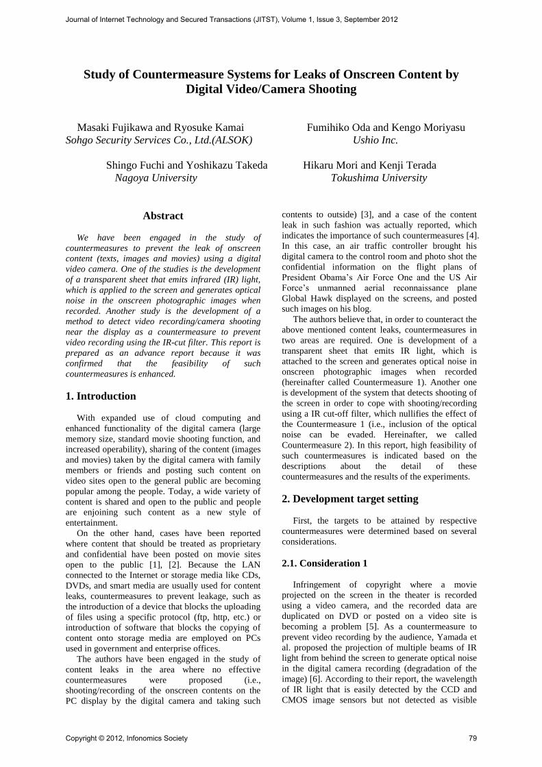
2.2.1. Why don’t you develop the IR emitting
display? The authors confirmed above wavelength
and phenomenon by placing an OHP sheet on which
multiple numbers of tulip flowers were printed on
the edge illuminated light guide panel, and photo
recording the OHP film illuminated by the infrared
light emitting LED (wavelength 870 nm) from
behind the light guide panel. The result of this
experiment confirmed that the human eye did not
recognize the IR light but the image sensor detected
the IR light as a whitish light, and the quality of the
image recorded was deteriorated (refer Figure 1).
The above experiment simulates the display
method of images on the LCD display panel, and in a
similar way, it is possible to impair the quality of the
video recording by placing IR light sources behind
the LCD panel. However, in order to introduce the
IR emitting display, replacement of the existing
display is necessary, which involves significant costs
as well as troublesome transportation, replacement,
and installation.
Figure 1. A photographic image illuminated with 25
infrared light emitting LEDs located behind the edge illuminated light guide plate.
2.2.2. Why not use an IR emitting panel using the
transparent light guide panel and the IR light?
The authors built a transparent panel that emits IR
light as a test piece inspired by the transparent
protection panel of a display screen. This is based on
the consideration that the existing display can be
used continuously without replacement and on the
consideration that such panel is more light weight
and thinner compared with a box-type IR light
emitting device, which is installed in front of the
display screen [7].
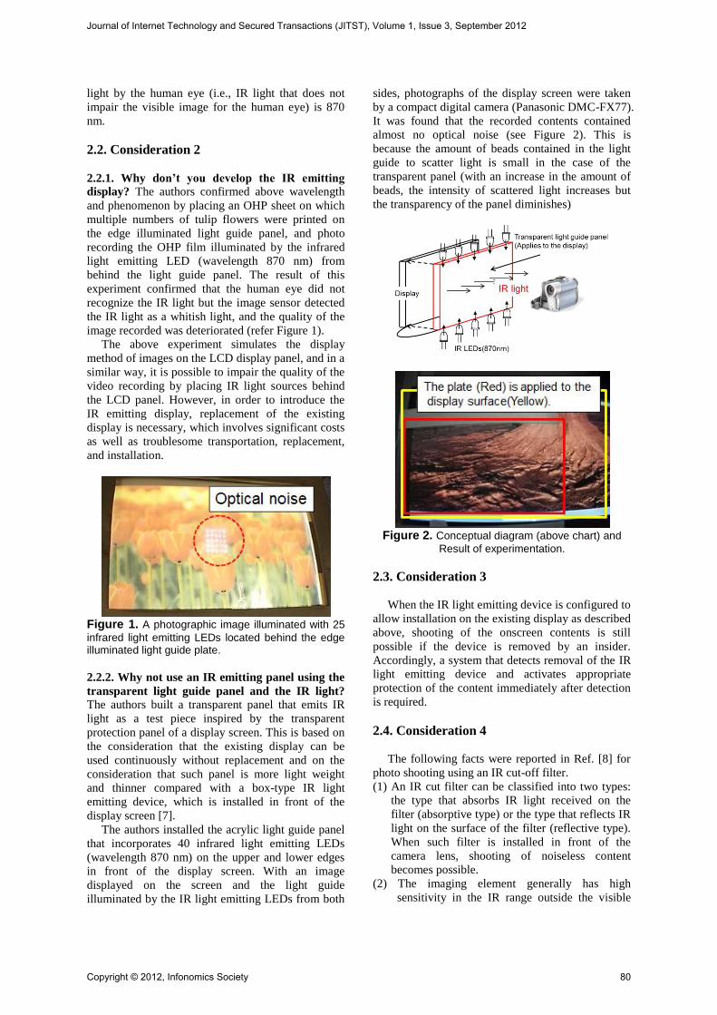
The authors installed the acrylic light guide panel
that incorporates 40 infrared light emitting LEDs
(wavelength 870 nm) on the upper and lower edges
in front of the display screen. With an image
displayed on the screen and the light guide
illuminated by the IR light emitting LEDs from both
sides, photographs of the display screen were taken
by a compact digital camera (Panasonic DMC-FX77).
It was found that the recorded contents contained
almost no optical noise (see Figure 2). This is
because the amount of beads contained in the light
guide to scatter light is small in the case of the
transparent panel (with an increase in the amount of
beads, the intensity of scattered light increases but
the transparency of the panel diminishes)
Figure 2. Conceptual diagram (above chart) and
Result of experimentation.
2.3. Consideration 3
When the IR light emitting device is configured to
allow installation on the existing display as described
above, shooting of the onscreen contents is still
possible if the device is removed by an insider.
Accordingly, a system that detects removal of the IR
light emitting device and activates appropriate
protection of the content immediately after detection
is required.
2.4. Consideration 4
The following facts were reported in Ref. [8] for
photo shooting using an IR cut-off filter.
(1) An IR cut filter can be classified into two types:
the type that absorbs IR light received on the
filter (absorptive type) or the type that reflects IR
light on the surface of the filter (reflective type).
When such filter is installed in front of the
camera lens, shooting of noiseless content
becomes possible.
(2) The imaging element generally has high
sensitivity in the IR range outside the visible
Journal of Internet Technology and Secured Transactions (JITST), Volume 1, Issue 3, September 2012
Copyright © 2012, Infonomics Society 80
range. Because of this, a filter with its IR light
cut-off ratio adjusted according to the
specifications of shooting of the digital camera
is installed in front of the imaging element.
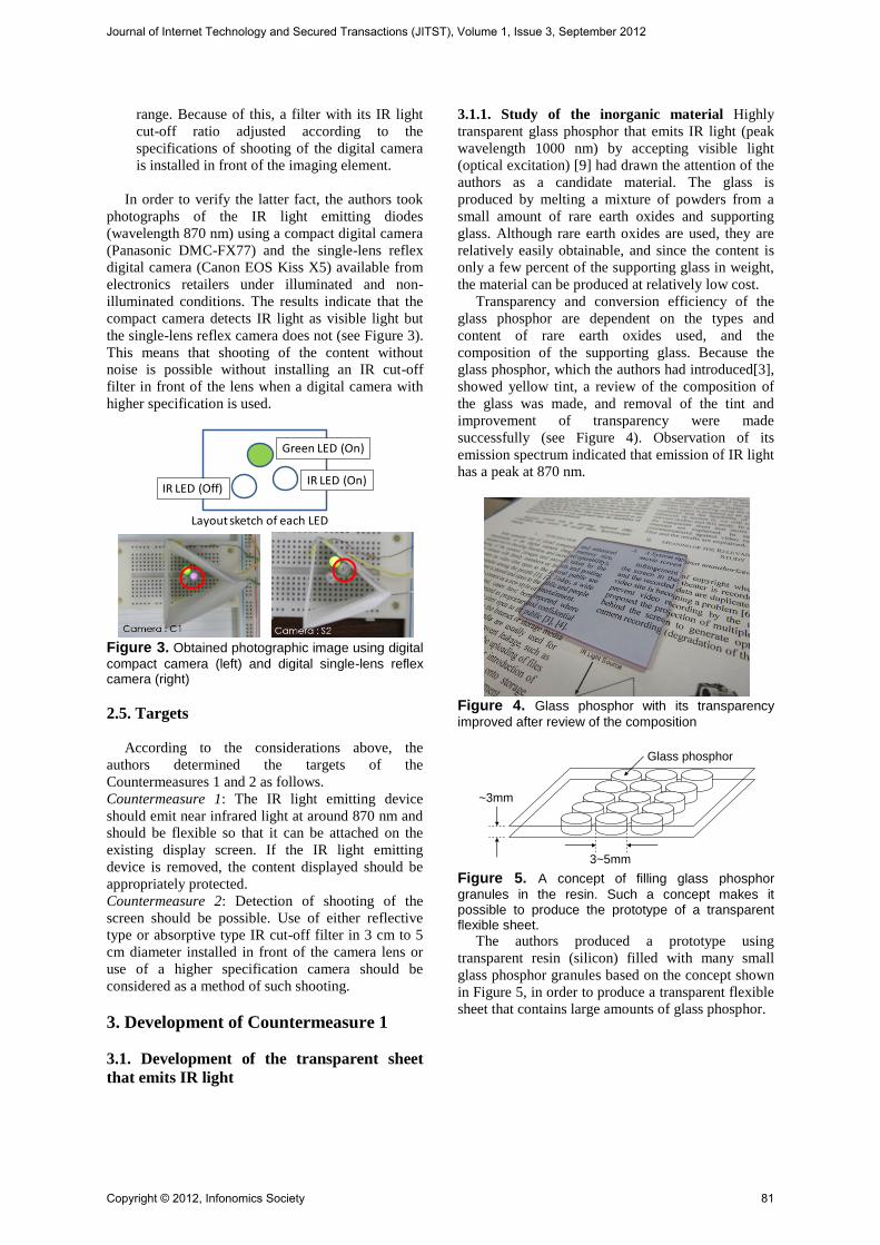
In order to verify the latter fact, the authors took
photographs of the IR light emitting diodes
(wavelength 870 nm) using a compact digital camera
(Panasonic DMC-FX77) and the single-lens reflex
digital camera (Canon EOS Kiss X5) available from
electronics retailers under illuminated and non-
illuminated conditions. The results indicate that the
compact camera detects IR light as visible light but
the single-lens reflex camera does not (see Figure 3).
This means that shooting of the content without
noise is possible without installing an IR cut-off
filter in front of the lens when a digital camera with
higher specification is used.
Figure 3. Obtained photographic image using digital
compact camera (left) and digital single-lens reflex camera (right)
2.5. Targets
According to the considerations above, the
authors determined the targets of the
Countermeasures 1 and 2 as follows.
Countermeasure 1: The IR light emitting device
should emit near infrared light at around 870 nm and
should be flexible so that it can be attached on the
existing display screen. If the IR light emitting
device is removed, the content displayed should be
appropriately protected.
Countermeasure 2: Detection of shooting of the
screen should be possible. Use of either reflective
type or absorptive type IR cut-off filter in 3 cm to 5
cm diameter installed in front of the camera lens or
use of a higher specification camera should be
considered as a method of such shooting.
3. Development of Countermeasure 1
3.1. Development of the transparent sheet
that emits IR light
3.1.1. Study of the inorganic material Highly
transparent glass phosphor that emits IR light (peak
wavelength 1000 nm) by accepting visible light
(optical excitation) [9] had drawn the attention of the
authors as a candidate material. The glass is
produced by melting a mixture of powders from a
small amount of rare earth oxides and supporting
glass. Although rare earth oxides are used, they are
relatively easily obtainable, and since the content is
only a few percent of the supporting glass in weight,
the material can be produced at relatively low cost.
Transparency and conversion efficiency of the
glass phosphor are dependent on the types and
content of rare earth oxides used, and the
composition of the supporting glass. Because the
glass phosphor, which the authors had introduced[3],
showed yellow tint, a review of the composition of
the glass was made, and removal of the tint and
improvement of transparency were made
successfully (see Figure 4). Observation of its
emission spectrum indicated that emission of IR light
has a peak at 870 nm.
Figure 4. Glass phosphor with its transparency
improved after review of the composition
Figure 5. A concept of filling glass phosphor
granules in the resin. Such a concept makes it possible to produce the prototype of a transparent flexible sheet.
The authors produced a prototype using
transparent resin (silicon) filled with many small
glass phosphor granules based on the concept shown
in Figure 5, in order to produce a transparent flexible
sheet that contains large amounts of glass phosphor.
Green LED (On)
IR LED (Off)IR LED (On)
Layout sketch of each LED
3~5mm
Glass phosphor
~3mm
Journal of Internet Technology and Secured Transactions (JITST), Volume 1, Issue 3, September 2012
Copyright © 2012, Infonomics Society 81
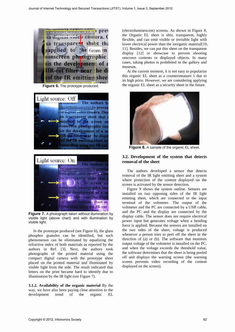
Figure 6. The prototype produced.
Figure 7. A photograph taken without illumination by
visible light (above chart) and with illumination by visible light.
In the prototype produced (see Figure 6), the glass
phosphor granules can be identified, but such
phenomenon can be eliminated by equalizing the
refractive index of both materials as reported by the
authors in Ref. [3]. Next, the authors took
photographs of the printed material using the
compact digital camera with the prototype sheet
placed on the printed material and illuminated by
visible light from the side. The result indicated that
letters on the print became hard to identify due to
illumination by the IR light (see Figure 7).
3.1.2. Availability of the organic material By the
way, we have also been paying close attention to the
development trend of the organic EL
(electroluminescent) screens. As shown in Figure 8,
the Organic EL sheet is shin, transparent, highly
flexible, and can emit visible or invisible light with
lower electrical power than the inorganic material[10,
11]. Besides, we can put this sheet on the transparent
display [12] or showcase to prevent shooting
onscreen contents or displayed objects. In many
cases, taking photos is prohibited in the gallery and
museum.
At the current moment, it is not easy to popularize
this organic EL sheet as a countermeasure 1 due to
its high price. However, we are considering applying
the organic EL sheet as a security sheet in the future.
Figure 8. A sample of the organic EL sheet.
3.2. Development of the system that detects
removal of the sheet
The authors developed a sensor that detects
removal of the IR light emitting sheet and a system
where protection of the content displayed on the
screen is activated by the sensor detection.
Figure 9 shows the system outline. Sensors are
installed on two opposing sides of the IR light
emitting sheet, which are connected to the input
terminal of the voltmeter. The output of the
voltmeter and the PC are connected by a USB cable,
and the PC and the display are connected by the
display cable. The sensor does not require electrical
power input but generates voltage when a bending
force is applied. Because the sensors are installed on
the two sides of the sheet, voltage is produced
whenever a person tries to peel off the sheet in the
direction of (a) or (b). The software that monitors
output voltage of the voltmeter is installed on the PC,
and when the voltage exceeds the threshold value,
the software determines that the sheet is being peeled
off and displays the warning screen (the warning
screen prevents video recording of the content
displayed on the screen).
Journal of Internet Technology and Secured Transactions (JITST), Volume 1, Issue 3, September 2012
Copyright © 2012, Infonomics Society 82
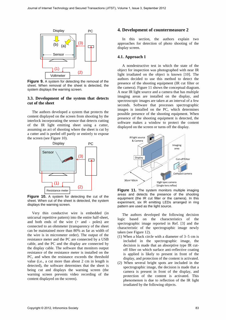
Figure 9. A system for detecting the removal of the
sheet. When removal of the sheet is detected, the system displays the warning screen.
3.3. Development of the system that detects
cut of the sheet
The authors developed a system that protects the
content displayed on the screen from shooting by the
interlock incorporating the sensor that detects cutting
of the IR light emitting sheet using a cutter,
assuming an act of shooting where the sheet is cut by
a cutter and is peeled off partly or entirely to expose
the screen (see Figure 10).
Figure 10. A system for detecting the cut of the
sheet. When cut of the sheet is detected, the system displays the warning screen.
Very thin conductive wire is embedded (in
unicursal repetitive pattern) into the entire half-sheet,
and both ends of the wire (+ and - poles) are
connected to an ohmmeter (transparency of the sheet
can be maintained more than 80% as far as width of
the wire is in micrometer order). The output of the
resistance meter and the PC are connected by a USB
cable, and the PC and the display are connected by
the display cable. The software that monitors output
resistance of the resistance meter is installed on the
PC, and when the resistance exceeds the threshold
value (i.e., a cut more than about 2 cm in length is
detected), the software determines that the sheet is
being cut and displays the warning screen (the
warning screen prevents video recording of the
content displayed on the screen).
4. Development of countermeasure 2
In this section, the authors explain two
approaches for detection of photo shooting of the
display screen.
4.1. Approach 1
A nondestructive test in which the state of the
object for inspection was photographed with near IR
light irradiated on the object is known [10]. The
authors decided to use this method to detect the
presence of the shooting equipment (IR cut filter or
the camera). Figure 11 shows the conceptual diagram.
A near IR light source and a camera that has multiple
imaging areas are installed on the display, and
spectroscopic images are taken at an interval of a few
seconds. Software that processes spectrographic
images is installed on the PC, which determines
possible presence of the shooting equipment. When
presence of the shooting equipment is detected, the
software makes a window to protect the content
displayed on the screen or turns off the display.
Figure 11. The system monitors multiple imaging
areas and detects the presence of the shooting equipment (the IR cut filter or the camera). In this experiment, six IR emitting LEDs arranged in ring pattern are used as the light source.
The authors developed the following decision
logic based on the characteristics of the
spectrographic image reported in Ref. [3] and the
characteristic of the spectrographic image newly
taken (see Figure 12).
(1) When a black circle with a diameter of 3–5 cm is
included in the spectrographic image, the
decision is made that an absorptive type IR cut-
off filter on which surface anti-reflective coating
is applied is likely to present in front of the
display, and protection of the content is activated.
(2) When several bright spots are included in the
spectrographic image, the decision is made that a
camera is present in front of the display, and
protection of the content is activated. This
phenomenon is due to reflection of the IR light
irradiated by the following objects.
(a)(b)
Sensor
Display
Voltmeter
PC
(1)(2)
(3)
Display
Resistance meter
PC
(1)(2)
(3)Sensor
IR light source& Camera
Cut-off Filter
Imagingarea
Display
Compact camera
30cm~60cmHigh-spec camera(single-lens reflex)
Journal of Internet Technology and Secured Transactions (JITST), Volume 1, Issue 3, September 2012
Copyright © 2012, Infonomics Society 83
Reflective type IR light cut-off filter
Absorptive type IR light cut-off filter
without anti-reflective coating (a cut-off
filter without such coating reflects about 4%
of light incident on its surface like
conventional glass)
Lens of the camera
Metal or plastic material (used as a body of
the camera)
When this decision logic is used, detection of
shooting with the IR cut-off filter installed in front of
the lens of the camera or shooting by the high
specification camera without the IR cutoff filter is
possible. However, the criteria for this decision logic
are not precise, and the possibility remains that
protection of the content may be erroneously
activated when glass, metallic, and/or plastic
material in a diameter of 3–5 cm not of a camera is
present in front of the display. Accordingly, the
authors are trying to improve the accuracy of the
decision in combination with the other image
processing techniques.
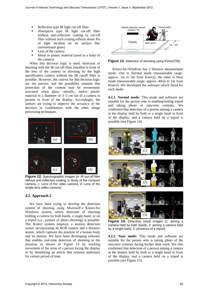
Figure 12. Spectrographic images (a: IR cut-off filter
without anti-reflective coaling, b: Body of the compact camera, c: Lens of the video camera, d: Lens of the single-lens reflex camera)
4.2. Approach 2
We have been trying to develop the detection
system of shooting using Microsoft’s Kinect-for
Windows system, where detection of shooting
holding a camera by both hands, a single hand, or on
a tripod (i.e., posture of photo shooting) is possible.
The Kinect system employs a motion detection
sensor incorporating an RGB camera and a distance
sensor, which captures the position of a human body
and its motion. We have been developing software
that enables real-time detection of shooting in the
situation as shown in Figure 13 by tracking
movement of the arms of a person facing the display
or by identifying an article that remains stationary
for certain period of time.
Figure 13. Detection of shooting using Kinect(TM).
Kinect-for-Windows has 2 distance measurement
mode: One is Normal mode (measureable range:
approx. 1m to 3m from Kinect), the other is Near
mode (measureable range: approx. 40cm to 1m from
Kinect). We developed the software which fitted for
each mode.
4.2.1. Normal mode: This mode and software are
suitable for the person who is standing/setting tripod
and taking photo of onscreen contents. We
confirmed that detection of a person aiming a camera
at the display held by both or a single hand in front
of the display, and a camera held on a tripod is
possible (see Figure 14).
Figure 14. Detection result images (1: aiming a
camera held by both hands, 2: aiming a camera held by a single hand, 3: presence of a tripod)
4.2.2. Near mode: This mode and software are
suitable for the person who is taking photo of the
onscreen contents during his/her desk work. We also
confirmed that detection of a person aiming a camera
at the display held by both or a single hand in front
of the display, and a camera held on a tripod is
possible (see Figure 15).
Display
Motion detection sensor
(KINECTTM)
1m ~ 3m
Tripod stand
Both arms
(a) (b)
(c) (d)
(1)
(2)
(3)
Journal of Internet Technology and Secured Transactions (JITST), Volume 1, Issue 3, September 2012
Copyright © 2012, Infonomics Society 84
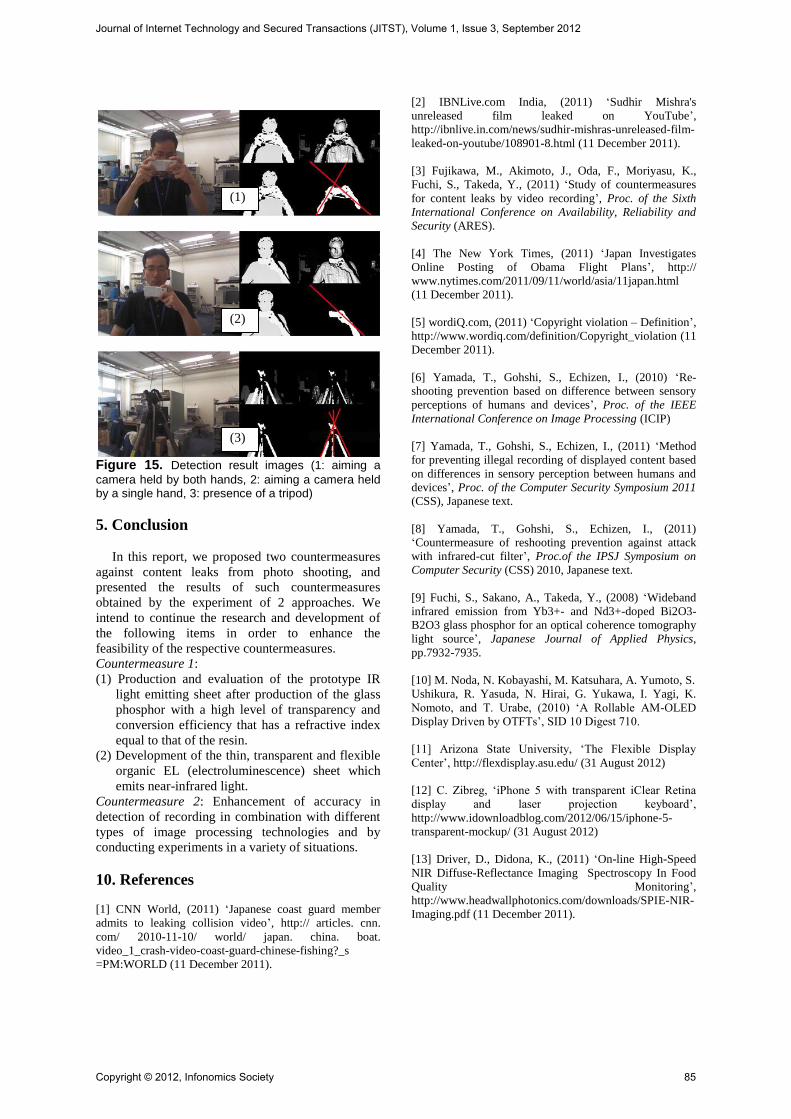
Figure 15. Detection result images (1: aiming a
camera held by both hands, 2: aiming a camera held by a single hand, 3: presence of a tripod)
5. Conclusion
In this report, we proposed two countermeasures
against content leaks from photo shooting, and
presented the results of such countermeasures
obtained by the experiment of 2 approaches. We
intend to continue the research and development of
the following items in order to enhance the
feasibility of the respective countermeasures.
Countermeasure 1:
(1) Production and evaluation of the prototype IR
light emitting sheet after production of the glass
phosphor with a high level of transparency and
conversion efficiency that has a refractive index
equal to that of the resin.
(2) Development of the thin, transparent and flexible
organic EL (electroluminescence) sheet which
emits near-infrared light.
Countermeasure 2: Enhancement of accuracy in
detection of recording in combination with different
types of image processing technologies and by
conducting experiments in a variety of situations.
10. References
[1] CNN World, (2011) ‘Japanese coast guard member
admits to leaking collision video’, http:// articles. cnn.
com/ 2010-11-10/ world/ japan. china. boat.
video_1_crash-video-coast-guard-chinese-fishing?_s
=PM:WORLD (11 December 2011).
[2] IBNLive.com India, (2011) ‘Sudhir Mishra's
unreleased film leaked on YouTube’,
http://ibnlive.in.com/news/sudhir-mishras-unreleased-film-
leaked-on-youtube/108901-8.html (11 December 2011).
[3] Fujikawa, M., Akimoto, J., Oda, F., Moriyasu, K.,
Fuchi, S., Takeda, Y., (2011) ‘Study of countermeasures
for content leaks by video recording’, Proc. of the Sixth
International Conference on Availability, Reliability and
Security (ARES).
[4] The New York Times, (2011) ‘Japan Investigates
Online Posting of Obama Flight Plans’, http://
www.nytimes.com/2011/09/11/world/asia/11japan.html
(11 December 2011).
[5] wordiQ.com, (2011) ‘Copyright violation – Definition’,
http://www.wordiq.com/definition/Copyright_violation (11
December 2011).
[6] Yamada, T., Gohshi, S., Echizen, I., (2010) ‘Re-
shooting prevention based on difference between sensory
perceptions of humans and devices’, Proc. of the IEEE
International Conference on Image Processing (ICIP)
[7] Yamada, T., Gohshi, S., Echizen, I., (2011) ‘Method
for preventing illegal recording of displayed content based
on differences in sensory perception between humans and
devices’, Proc. of the Computer Security Symposium 2011
(CSS), Japanese text.
[8] Yamada, T., Gohshi, S., Echizen, I., (2011)
‘Countermeasure of reshooting prevention against attack
with infrared-cut filter’, Proc.of the IPSJ Symposium on
Computer Security (CSS) 2010, Japanese text.
[9] Fuchi, S., Sakano, A., Takeda, Y., (2008) ‘Wideband
infrared emission from Yb3+- and Nd3+-doped Bi2O3-
B2O3 glass phosphor for an optical coherence tomography
light source’, Japanese Journal of Applied Physics,
pp.7932-7935.
[10] M. Noda, N. Kobayashi, M. Katsuhara, A. Yumoto, S.
Ushikura, R. Yasuda, N. Hirai, G. Yukawa, I. Yagi, K.
Nomoto, and T. Urabe, (2010) ‘A Rollable AM-OLED
Display Driven by OTFTs’, SID 10 Digest 710.
[11] Arizona State University, ‘The Flexible Display
Center’, http://flexdisplay.asu.edu/ (31 August 2012)
[12] C. Zibreg, ‘iPhone 5 with transparent iClear Retina
display and laser projection keyboard’,
http://www.idownloadblog.com/2012/06/15/iphone-5-
transparent-mockup/ (31 August 2012)
[13] Driver, D., Didona, K., (2011) ‘On-line High-Speed
NIR Diffuse-Reflectance Imaging Spectroscopy In Food
Quality Monitoring’,
http://www.headwallphotonics.com/downloads/SPIE-NIR-
Imaging.pdf (11 December 2011).
(2)
(1)
(3)
Journal of Internet Technology and Secured Transactions (JITST), Volume 1, Issue 3, September 2012
Copyright © 2012, Infonomics Society 85


![Study of Countermeasure Systems for Leaks of Onscreen ...infonomics-society.ie/wp-content/uploads/jitst/published-papers/volu… · becoming a problem [5]. As a countermeasure to](https://static.fdocuments.us/doc/165x107/6090b6c7ccfff16dc326ef30/study-of-countermeasure-systems-for-leaks-of-onscreen-infonomics-becoming-a.jpg)